US6714969B1 - Mobile terminal with integrated host application software - Google Patents
Mobile terminal with integrated host application softwareDownload PDFInfo
- Publication number
- US6714969B1 US6714969B1US09/570,961US57096100AUS6714969B1US 6714969 B1US6714969 B1US 6714969B1US 57096100 AUS57096100 AUS 57096100AUS 6714969 B1US6714969 B1US 6714969B1
- Authority
- US
- United States
- Prior art keywords
- terminal
- bar code
- script
- software
- wireless
- Prior art date
- Legal status (The legal status is an assumption and is not a legal conclusion. Google has not performed a legal analysis and makes no representation as to the accuracy of the status listed.)
- Expired - Lifetime
Links
Images


Classifications
- G—PHYSICS
- G06—COMPUTING OR CALCULATING; COUNTING
- G06F—ELECTRIC DIGITAL DATA PROCESSING
- G06F1/00—Details not covered by groups G06F3/00 - G06F13/00 and G06F21/00
- G06F1/16—Constructional details or arrangements
- G06F1/1613—Constructional details or arrangements for portable computers
- G06F1/1615—Constructional details or arrangements for portable computers with several enclosures having relative motions, each enclosure supporting at least one I/O or computing function
- G06F1/1616—Constructional details or arrangements for portable computers with several enclosures having relative motions, each enclosure supporting at least one I/O or computing function with folding flat displays, e.g. laptop computers or notebooks having a clamshell configuration, with body parts pivoting to an open position around an axis parallel to the plane they define in closed position
- G—PHYSICS
- G06—COMPUTING OR CALCULATING; COUNTING
- G06F—ELECTRIC DIGITAL DATA PROCESSING
- G06F1/00—Details not covered by groups G06F3/00 - G06F13/00 and G06F21/00
- G06F1/16—Constructional details or arrangements
- G06F1/1613—Constructional details or arrangements for portable computers
- G06F1/1626—Constructional details or arrangements for portable computers with a single-body enclosure integrating a flat display, e.g. Personal Digital Assistants [PDAs]
- G—PHYSICS
- G06—COMPUTING OR CALCULATING; COUNTING
- G06F—ELECTRIC DIGITAL DATA PROCESSING
- G06F1/00—Details not covered by groups G06F3/00 - G06F13/00 and G06F21/00
- G06F1/16—Constructional details or arrangements
- G06F1/1613—Constructional details or arrangements for portable computers
- G06F1/1632—External expansion units, e.g. docking stations
- G—PHYSICS
- G06—COMPUTING OR CALCULATING; COUNTING
- G06F—ELECTRIC DIGITAL DATA PROCESSING
- G06F1/00—Details not covered by groups G06F3/00 - G06F13/00 and G06F21/00
- G06F1/16—Constructional details or arrangements
- G06F1/1613—Constructional details or arrangements for portable computers
- G06F1/1633—Constructional details or arrangements of portable computers not specific to the type of enclosures covered by groups G06F1/1615 - G06F1/1626
- G06F1/1656—Details related to functional adaptations of the enclosure, e.g. to provide protection against EMI, shock, water, or to host detachable peripherals like a mouse or removable expansions units like PCMCIA cards, or to provide access to internal components for maintenance or to removable storage supports like CDs or DVDs, or to mechanically mount accessories
- G—PHYSICS
- G06—COMPUTING OR CALCULATING; COUNTING
- G06F—ELECTRIC DIGITAL DATA PROCESSING
- G06F1/00—Details not covered by groups G06F3/00 - G06F13/00 and G06F21/00
- G06F1/16—Constructional details or arrangements
- G06F1/1613—Constructional details or arrangements for portable computers
- G06F1/1633—Constructional details or arrangements of portable computers not specific to the type of enclosures covered by groups G06F1/1615 - G06F1/1626
- G06F1/1684—Constructional details or arrangements related to integrated I/O peripherals not covered by groups G06F1/1635 - G06F1/1675
- G06F1/1696—Constructional details or arrangements related to integrated I/O peripherals not covered by groups G06F1/1635 - G06F1/1675 the I/O peripheral being a printing or scanning device
- G—PHYSICS
- G06—COMPUTING OR CALCULATING; COUNTING
- G06F—ELECTRIC DIGITAL DATA PROCESSING
- G06F1/00—Details not covered by groups G06F3/00 - G06F13/00 and G06F21/00
- G06F1/16—Constructional details or arrangements
- G06F1/18—Packaging or power distribution
- G06F1/181—Enclosures
- G—PHYSICS
- G06—COMPUTING OR CALCULATING; COUNTING
- G06F—ELECTRIC DIGITAL DATA PROCESSING
- G06F16/00—Information retrieval; Database structures therefor; File system structures therefor
- G06F16/40—Information retrieval; Database structures therefor; File system structures therefor of multimedia data, e.g. slideshows comprising image and additional audio data
- G06F16/43—Querying
- G06F16/432—Query formulation
- G06F16/434—Query formulation using image data, e.g. images, photos, pictures taken by a user
- G—PHYSICS
- G06—COMPUTING OR CALCULATING; COUNTING
- G06F—ELECTRIC DIGITAL DATA PROCESSING
- G06F16/00—Information retrieval; Database structures therefor; File system structures therefor
- G06F16/90—Details of database functions independent of the retrieved data types
- G06F16/95—Retrieval from the web
- G06F16/955—Retrieval from the web using information identifiers, e.g. uniform resource locators [URL]
- G06F16/9554—Retrieval from the web using information identifiers, e.g. uniform resource locators [URL] by using bar codes
- G—PHYSICS
- G06—COMPUTING OR CALCULATING; COUNTING
- G06F—ELECTRIC DIGITAL DATA PROCESSING
- G06F3/00—Input arrangements for transferring data to be processed into a form capable of being handled by the computer; Output arrangements for transferring data from processing unit to output unit, e.g. interface arrangements
- G06F3/01—Input arrangements or combined input and output arrangements for interaction between user and computer
- G06F3/03—Arrangements for converting the position or the displacement of a member into a coded form
- G06F3/033—Pointing devices displaced or positioned by the user, e.g. mice, trackballs, pens or joysticks; Accessories therefor
- G06F3/0354—Pointing devices displaced or positioned by the user, e.g. mice, trackballs, pens or joysticks; Accessories therefor with detection of 2D relative movements between the device, or an operating part thereof, and a plane or surface, e.g. 2D mice, trackballs, pens or pucks
- G06F3/03545—Pens or stylus
- G—PHYSICS
- G06—COMPUTING OR CALCULATING; COUNTING
- G06K—GRAPHICAL DATA READING; PRESENTATION OF DATA; RECORD CARRIERS; HANDLING RECORD CARRIERS
- G06K17/00—Methods or arrangements for effecting co-operative working between equipments covered by two or more of main groups G06K1/00 - G06K15/00, e.g. automatic card files incorporating conveying and reading operations
- G06K17/0022—Methods or arrangements for effecting co-operative working between equipments covered by two or more of main groups G06K1/00 - G06K15/00, e.g. automatic card files incorporating conveying and reading operations arrangements or provisions for transferring data to distant stations, e.g. from a sensing device
- G—PHYSICS
- G06—COMPUTING OR CALCULATING; COUNTING
- G06K—GRAPHICAL DATA READING; PRESENTATION OF DATA; RECORD CARRIERS; HANDLING RECORD CARRIERS
- G06K7/00—Methods or arrangements for sensing record carriers, e.g. for reading patterns
- G06K7/10—Methods or arrangements for sensing record carriers, e.g. for reading patterns by electromagnetic radiation, e.g. optical sensing; by corpuscular radiation
- G06K7/10544—Methods or arrangements for sensing record carriers, e.g. for reading patterns by electromagnetic radiation, e.g. optical sensing; by corpuscular radiation by scanning of the records by radiation in the optical part of the electromagnetic spectrum
- G06K7/10821—Methods or arrangements for sensing record carriers, e.g. for reading patterns by electromagnetic radiation, e.g. optical sensing; by corpuscular radiation by scanning of the records by radiation in the optical part of the electromagnetic spectrum further details of bar or optical code scanning devices
- G06K7/10881—Methods or arrangements for sensing record carriers, e.g. for reading patterns by electromagnetic radiation, e.g. optical sensing; by corpuscular radiation by scanning of the records by radiation in the optical part of the electromagnetic spectrum further details of bar or optical code scanning devices constructional details of hand-held scanners
- H—ELECTRICITY
- H04—ELECTRIC COMMUNICATION TECHNIQUE
- H04L—TRANSMISSION OF DIGITAL INFORMATION, e.g. TELEGRAPHIC COMMUNICATION
- H04L51/00—User-to-user messaging in packet-switching networks, transmitted according to store-and-forward or real-time protocols, e.g. e-mail
- H—ELECTRICITY
- H04—ELECTRIC COMMUNICATION TECHNIQUE
- H04L—TRANSMISSION OF DIGITAL INFORMATION, e.g. TELEGRAPHIC COMMUNICATION
- H04L51/00—User-to-user messaging in packet-switching networks, transmitted according to store-and-forward or real-time protocols, e.g. e-mail
- H04L51/21—Monitoring or handling of messages
- H04L51/216—Handling conversation history, e.g. grouping of messages in sessions or threads
- H—ELECTRICITY
- H04—ELECTRIC COMMUNICATION TECHNIQUE
- H04L—TRANSMISSION OF DIGITAL INFORMATION, e.g. TELEGRAPHIC COMMUNICATION
- H04L51/00—User-to-user messaging in packet-switching networks, transmitted according to store-and-forward or real-time protocols, e.g. e-mail
- H04L51/21—Monitoring or handling of messages
- H04L51/222—Monitoring or handling of messages using geographical location information, e.g. messages transmitted or received in proximity of a certain spot or area
- H—ELECTRICITY
- H04—ELECTRIC COMMUNICATION TECHNIQUE
- H04L—TRANSMISSION OF DIGITAL INFORMATION, e.g. TELEGRAPHIC COMMUNICATION
- H04L61/00—Network arrangements, protocols or services for addressing or naming
- H—ELECTRICITY
- H04—ELECTRIC COMMUNICATION TECHNIQUE
- H04W—WIRELESS COMMUNICATION NETWORKS
- H04W88/00—Devices specially adapted for wireless communication networks, e.g. terminals, base stations or access point devices
- H04W88/02—Terminal devices
- H04W88/06—Terminal devices adapted for operation in multiple networks or having at least two operational modes, e.g. multi-mode terminals
- H—ELECTRICITY
- H04—ELECTRIC COMMUNICATION TECHNIQUE
- H04W—WIRELESS COMMUNICATION NETWORKS
- H04W4/00—Services specially adapted for wireless communication networks; Facilities therefor
- H—ELECTRICITY
- H04—ELECTRIC COMMUNICATION TECHNIQUE
- H04W—WIRELESS COMMUNICATION NETWORKS
- H04W74/00—Wireless channel access
- H—ELECTRICITY
- H04—ELECTRIC COMMUNICATION TECHNIQUE
- H04W—WIRELESS COMMUNICATION NETWORKS
- H04W76/00—Connection management
- H04W76/10—Connection setup
Definitions
- the inventionrelates to integrating host application software with data collection devices (e.g., bar code scanners) located on remote, wireless terminals.
- data collection devicese.g., bar code scanners
- the bar code symbolitself is a coded pattern of indicia comprised of, for example, a series of bars of various widths spaced apart from one another to form spaces of various widths, the bars and spaces having different light reflecting characteristics.
- the readerselectro-optically transform the graphic indicia into electrical signals which are decoded into alpha-numeric characters that are intended to be descriptive of the article or a characteristic thereof. Such characters typically are represented in digital form, and utilized as an input to a data processing system for applications in point of sale processing, inventory control and the like.
- Known scanning systemscomprise a light source for generating a light beam incident on a bar code symbol and a light receiver for receiving the reflected light and decoding and information contained in the bar code symbol accordingly.
- the readersmay comprise a flying spot scanning system wherein the light beam is scanned rapidly across a bar code symbol to be read or a fixed field of view reading system wherein the bar code symbol to be read is illuminated as a whole and a CCD (Charge Coupled Device) array is provided for detecting the light reflected from the bar code symbol.
- CCDCharge Coupled Device
- Known hand-held optical readersare often in the shape of a gun having a handle portion and a barrel portion.
- the reading window through which the light beam passesis generally located at the end face of the barrel portion, and the reader is aimed at the indicia to be read by the operator holding the handle portion.
- a triggeris situated in the region of the junction between the handle portion and the barrel portion for operation by the user to actuate the optical reader.
- the down-loaded datamay be raw data or data that has been processed within the hand-held computer.
- Data collectioncan be carried out by entering information to the hand-held computer via a keypad, or by incorporating in the computer an optical reader for example for reading bar code symbols, or incorporating a reader for reading a magnetic card strip.
- an optical readerfor example for reading bar code symbols
- incorporating a reader for reading a magnetic card stripFor example when information about various products is required during inventorying, those products may bear bar code symbols or magnetic strips, or have associated magnetic strip cards which are read by the hand-held computer.
- the data collectedcan be transferred from the hand-held computer to a central or peripheral device by known means such as radio frequency radio links, wired connections, infra-red communications or other known transmission arrangements.
- the inventionfeatures a new method of integrating host application software with data collection devices (e.g., bar code scanners) located on remote, wireless terminals.
- a data collection objectexecutes on the host computer, using a predetermined interface between the host application software and the data collection object. That interface, and the communications between the host application software and the data collection object, are configured so that to the host application software the data collection device appears to be local hardware on the host computer.
- the data collection objectcreates and executes threads of execution for controlling operation of the data collection device, with the threads communicating with the remote terminals via a host computer transport layer, the wireless link, and a remote computer transport layer at the remote terminals.
- a data collection device driver on the remote terminalreceives communications from the data collection object, and returns information to the data collection object, over the remote computer transport layer, wireless link, and host computer transport layer.
- the data collection objectmay be implemented as a COM.
- Communications between the remote terminal and the host computermay be over an Internet or Intranet network.
- the data collection devicemay be a bar code scanner, and the data collection object may be a bar code scanning object.
- a portable computer devicecomprising a main body and at least one data collection/communications module connectable to the main body, the main body including an interface for connection with the module, a processor for processing information received from the module and a communication link for exchanging information with a host. Because of the modular arrangement the device may be easily adapted to different applications without the requirement to manufacture costly customized systems or to modify such systems which would prove expensive and complex.
- the main bodymay include a visual display, for example an LCD display.
- the main bodymay also comprise a keypad.
- the modulesmay comprise an image capture module, a laser scanner module and/or a multi-media module.
- the modulespreferably include digital signal processing sub-systems which may be of a single design and programmable as appropriate.
- the modulesmay comprise pre-processors for pre-processing information prior to transfer to the main body to reduce the burden on the processor in the main body.
- the modulemay be movably mounted on or relative to the main body, and in particular to the display on the main body—for example it may be hinged pivotally or rotatably mounted.
- the devicemay be configured for connection with the Internet.
- a communication system for a bar code scannercomprising a control host, a scanning control object working therein and a remote client associated with the bar code scanner wherein the scanning control object communicates with the remote client to control the bar code scanner and the scanning control object is implemented as an OLE control. Accordingly there is provided a system capable of seamless communication between the scanning control and the remote client.
- the host and the scanning object controlmay communicate and integrate via interfaces.
- the scanning control objectmay create separate threads of execution for controlling communication with the remote client.
- the separate threads of executionmay include send, receive and synchronize bar code scanner transaction commands.
- the scanning control objectmay be arranged to communicate with the remote client over an Internet or Intranet link and/or by wireless communication.
- FIG. 1is a perspective view of an optical reader according to the present invention from above and the rear;
- FIG. 2is a perspective view of the optical reader of FIG. 1 from above and the front;
- FIG. 3is a perspective view of the optical reader from the front and tilted upwardly;
- FIG. 4is a view of the optical reader from the front
- FIG. 5is a view of the optical reader from below
- FIG. 6is a view of the optical reader from above showing hidden detail
- FIG. 7is a side view of the optical reader showing hidden detail
- FIG. 8is a sectional view of the optical reader along the line A—A shown in FIG. 7;
- FIG. 9shows a portable computer device according to another aspect of the invention.
- FIG. 10is a block diagram of an image capture module for the device of FIG. 9;
- FIG. 11is a block diagram of a multi-media module for the device of FIG. 9;
- FIG. 12is a perspective view of a variation of the device of FIG. 9;
- FIG. 13is a block diagram showing the components of a distributed mail delivery service according to another aspect of the invention.
- FIG. 14is a flow chart showing operation of a client portion of the service of FIG. 13;
- FIG. 15is a flow chart showing operation of a server portion of the service of FIG. 13;
- FIG. 16illustrates a block diagram of a conventional wireless communication system with a terminal emulation program installed on the mobile units
- FIG. 17illustrates a flow chart illustrating an access point's action upon receiving a packet from a mobile unit according to the prior art
- FIG. 18is a block diagram of a general purpose interface reader application according to another aspect of the invention.
- FIG. 19shows the interface between a scanning control and a control container according to a further aspect of the invention.
- FIG. 20shows multiple threads of execution maintained by the control of FIG. 18;
- FIG. 21shows schematically the packaging of the products for shipment according to an embodiment of the present invention
- FIG. 22is a flow diagram illustrating the operation of the software within the scanner
- FIG. 23is a sectional view of a hand-held scanner together with a host computer
- FIG. 24is a perspective view of the arrangement of FIG. 23 in use
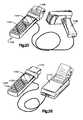
- FIG. 25shows a printer/scanner assembly suitable for use with the present invention.
- FIG. 26shows a further printer/scanner assembly.
- the optical readerhas a rear end 4 and a generally planar front end 5 , an upper face 2 a and opposed to that a lower face 2 b.
- the optical readerincludes a generally bar-shaped elongate housing indicated generally by the reference numeral 1 , having two generally opposed long broad upper and lower faces 2 a, 2 b (see also FIG. 7 ), two generally opposed long, shallow side faces 3 , a rear end 4 and a front end 5 (see also FIG. 6 ).
- the upper and lower faces 2 a, 2 b of the readercomprise side edges having substantially straight front portions tapering inwardly towards the front edge which is of convex shape having a large radius of curvature.
- the rear portions of the side edgescurve inwardly and meet so that the rear end 4 of the housing is generally elliptical in shape when viewed from above.
- the rear endis interrupted by a recessed connector 6 which is described in more detail below.
- the housingis configured to be held by a user with the rear end mounted in the palm of the user and it will be seen, therefore, that the curved end of the housing when viewed from above will facilitate holding by the user.
- the side faces 3 of the housingcomprise substantially parallel downwardly curved long edges and a substantially straight front edge.
- a bulbous convex rear portion 7extends from the rear end of the upper face to approximately the centre of the lower edge.
- a concave groove 8is provided in the frontward part of the bulbous portion 7 extending around both sides of the bulbous portion 7 to approximately the mid point of the bulbous portion 7 on either side.
- the reading arrangementmay be any known conventional arrangement, for example a “flying spot” optical scanner or a “field of view” optical reader.
- the arrangementwill include a light generating source such as a laser diode, a beam focusing or directing arrangement and a light receiving device.
- a rapidly oscillatable scan componentsuch as a mirror is provided to scan the light beam across an indicia to be read.
- the laser diodeitself can be oscillated.
- the readeris a field of view optical reader a charge coupled device (CCD) array, or a photodetector arrangement is provided to detect the reflected light beam.
- CCDcharge coupled device
- a scan trigger 9is provided on the upper surface 2 a of the housing 1 .
- the trigger 9comprises a cut-out strip extending transverse to the longitudinal axis of the housing 1 and across the whole of the upper face and part of each of the side faces 3 and is situated approximately half way along the upper face 2 a.
- the trigger 9is activated by depression and is positioned along the housing 1 such that it is easily actuable by the operator when the reader is held in the operator's hand.
- the trigger mechanismitself may be of any known arrangement; for example the trigger may be spring-loaded and have contacts which form a circuit with contacts within the housing when the trigger is depressed to actuate the reading arrangement.
- Powermay therefore be conserved as the reader will only be activated when the trigger is depressed enabling the operator to leave the reader idle when no indicia are to be read.
- the triggeris positioned with ergonomic considerations in mind, the reader can be simply and quickly operated by the user with minimum discomfort.
- a scanning window 10is positioned on the front face 5 of the reader. Light generated by the reading arrangement passes through the window 10 and is reflected and scattered back through the window 10 by a bar code symbol 11 . Accordingly the reader can be easily and accurately aimed at the bar code symbol 11 to be read (as shown illustratively in FIG. 2 ). As a result the bar code symbol 11 can be rapidly located by the user and read by the reader with a minimum amount of time wasted attempting to locate the bar code symbol 11 . Accordingly both operator time and usage time can be reduced which is of particular relevance in battery-powered hand-held readers.
- the batteries 12 for the hand-held readerare stored in the bulbous portion 7 towards the rear and aligned with the longitudinal axis of the reader.
- the batteries 12are disposed along a curved surface matching the curvature of the bulbous portion.
- a strap 13can be attached to the reader, for example towards the rear of the bulbous portion 7 for placing around the operator's wrist such that, in the event of the reader being inadvertently released from the grip of the user, it is still held to the user by the strap 13 .
- a keypad 14 and a display 15are also provided on the upper face of the reader.
- the keypad 14is not shown in FIG. 6 for the purpose of clarity).
- the keypad 14may be used to initialize the reading arrangement such that identification information concerning the user is entered into the system.
- the keypad 14may be used to enter predetermined codes or information concerning modes of operation of the reader or to carry out cancellation or manipulation operations on information provided by the reader.
- the display 15may display information relating to the mode of operation of the reader, or display check information relating to the item carrying the bar code symbol being read together with background information such as the time, date, and confirmation of the operator's identity.
- the display 15is a liquid crystal display (LCD).
- the reading arrangementcan process information derived from the bar code symbols directly or can send raw data to an external processing device which can then process the information accordingly.
- information derived by the reader from bar code symbolscan be transferred to a memory device in order that a database of information can be built up. For example where the reader is used at a point of sale, buying patterns can be stored and analyzed. Alternatively, if the reader is being used for inventorying purposes then the inventory information can be stored.
- the optical readercan transmit information in a variety of manners. In the embodiments shown various different transmitting devices are provided; in practice only one or more of the devices need be provided depending on the particular use to which the reader is to be put. For example the information may be transmitted by an acoustic modem 16 .
- informationcan be stored in a buffer memory within the reader and then down-loaded by the acoustic modem 16 at predetermined intervals.
- the display 15could indicate when information was to be down-loaded.
- an interface connectorfor example an RS41 connector is designated by reference numeral 6 and provided at the rear of the reader. Suitable cabling can be inserted into the connector 6 to down-load information or alternatively to load data into the reader for example relating to the mode of operation.
- the display 15could provide an indication of the functioning of the connector.
- the cablecould be permanently connected to the reader as the connector 6 is provided at the rear of the reader and hence would not be obscured by the user's hand.
- the connector 6could be connected to a cable for loading or down-loading of information when required and, for example, when indicated by display 15 .
- a radio 17 or other transmitting devicecan be provided within the housing 1 to allow real time data communication.
- the radio 17could comprise a transmitter and a receiver in order that information can be sent to and from a remote processor.
- the radio linkcould be replaced by an infra-red communication link or other wireless link of known type. Because the reader is of ergonomic design, the transfer of information is easily carried out while the reader is actually in use, if required.
- the readermay be configured for connection to a telecommunications network or computer network, for example the “Internet”.
- the readermay be of particular use is in relation to the worldwide web.
- the address of the siteknown as the universal resource locator (URL).
- URLuniversal resource locator
- those URL'sare long and complex, and are time consuming to enter and check manually.
- the URLcan, despite many checks, still give rise to error.
- the problemis exacerbated in the case of computer illiterate users.
- the proposed manner of overcoming this problemis to encode the URL address in a bar code symbol and read the bar code symbol with the reader for automatic access to the corresponding web site, which will be quick and accurate, giving rise to far less margin for error.
- the readermay be used to interface with a terminal for entry of the URL address or could be used independently.
- one or more finger gripsmay be provided at locations where, in use, the operator's fingers or other parts of the operator's hand would contact the reader.
- the finger gripwould comprise a molded rubber portion having raised elements to achieve traction on the finger or palm.
- Such finger gripscould be provided, for example, on the bulbous portion 7 (as shown schematically in FIG. 5 by reference numeral 18 ) or the concave groove 8 therein, on or in the vicinity of the trigger portion or in areas of the upper surface 2 a where the operator's thumb might rest.
- the hand-held optical reader described hereinis ergonomically shaped for maximum user ease and comfort, allowing increased efficiency and user-friendliness.
- Features such as the trigger 9 and finger grips 18are positioned for optimum user operability. It will be appreciated that such features may be presented symmetrically in order to allow the terminal to be used by either left or right-handed users, or alternatively the handset may be produced in both left and right-handed versions.
- the reading window 10is positioned for improved accuracy and ease of use, and features such as the key pad 14 and display 15 are positioned for ease of access and reference by the user.
- the devicemay be either wireless or connected to a central processor by a cord leading from the connector 6 provided at a convenient position on the terminal.
- the devicecan be powered by batteries 12 located conveniently along the curve of the bulbous grip portion 7 or could in the alternative be powered by a removable, rechargeable battery pack or via a cord into the above-mentioned interconnector or another connector.
- FIG. 9a data collection device comprising an improvement over known arrangements.
- the devicecomprises a portable hand-held computer for collecting data and down-loading the raw processed data to a central or peripheral device.
- the devicedesignated generally as 20 comprises a main body 21 and interchangeable data collection modules 22 a, 22 b, 22 c.
- the main body 21is provided internally with data processing means (not shown) and also comprises a display screen 23 , for example an LCD display screen capable of displaying video images, a data collection module interface 24 , an optional input information keypad 25 and a communication link 26 which may comprise radio frequency or infra-red transmitting means or an interface for down-loading information to a central or peripheral device via a physical cable.
- a display screen 23for example an LCD display screen capable of displaying video images
- a data collection module interface 24an optional input information keypad 25 and a communication link 26 which may comprise radio frequency or infra-red transmitting means or an interface for down-loading information to a central or peripheral device via a physical cable.
- the LCD display 23 and input keypad 25are optional features.
- the main bodyis shown schematically in FIG. 9; in practice it could assume an ergonomic shape such as that shown in FIGS. 1 to 7 , suitable interfaces etc. being positioned as appropriate, for example at respective ends of the module.
- the devicemay transfer information to a host via any electronic data transfer scheme—for example the system could also use cellular-based telephone channels.
- the devicecould be configured for connection to a telecommunications network or computer network, for example the “Internet”.
- the data collection modulesare interchangeable with one another and may be, for example, CCD (Charge Coupled Device) based image, video and bar code symbol data capture modules, audio transducers for collecting and receiving sound information, laser image scanners or combined multi-media data collection modules.
- CCDCharge Coupled Device
- An image capture module using a CCDcould be used for capturing images of objects for storage or use by a processor application carried out by the main body or by a host, such images including for example people, landscapes, homes and vehicles for reference applications.
- the imagercould be used for one dimensional or two dimensional bar code symbols for decoding data capture.
- a laser optical reader scanning module and decoderwould be used generally for bar code data capture and decoding only.
- a multi-media module 22is shown in FIG. 11 and discussed in more detail with reference to that figure below.
- Such a modulecould contain a circuitry for image/video capture, audio capture and playback and a cellular telephony sub-system.
- Such a modulewould be of particular use in tele-conferencing and live video communications over cellular networks from the portable unit.
- the desired data collection module 22 a,b,cis connected to the main body 21 by the interface 24 on the main body which mates with an interface 27 on the module.
- Any suitable known interface componentscan be used but the components should be strong, relatively inflexible, durable and suitable for frequent disconnection and reconnection.
- the modulesare powered by a power supply within the main body of the portable computing device and may be partially or totally controlled by software drivers within the main body.
- dedicated signal processing electronics within the modulescan be arranged to perform up-front data processing as a result of which a common bus architecture to the main body is shared by all of the modules. As a result their interchangeability is enhanced.
- FIG. 10A suitable architecture for an optical media capture module 28 (for example containing a CCD imager or laser scanner) is shown in FIG. 10 .
- Each modulemay contain only the media capture electronics without any pre-processing capability or, as discussed above, preferably contains dedicated or programmable analog components 32 and digital signal processing (DSP) components 33 to ease the processing load placed on the central processing unit of the main body 21 .
- DSPdigital signal processing
- the digital signal processing sub-system 32 , 33 in the modulemay be of a single electronic design common to different modules, and which is either programmed in the factory or customized on purchase or programmable by the user to perform the functions in processors if required by the particular media module.
- This function programmabilityis expected to be mainly through software, since the module processing electronics are flexible, and these software components may be one-time or dynamically loaded to the module via the main body central processing unit. Accordingly the range of components that require manufacture is decreased, appropriate dedicated parts of the components being selectable for a desired use, or a portion of the mode of operation being borne by software.
- the module 28collects information via the CCD imager or laser scanner in analog form which is transferred either serially or by conversion into a parallel format.
- the analog signalis then processed by the digital signal processing sub-system 32 , 33 and forwarded to an interface bus 34 from which the information is transferred to the main body of the portable computing device.
- the signal processing electronicspreferably perform up-front data processing such that a common bus architecture to the portable computing device 21 can be achieved.
- the multi-media module 22includes circuitry for image/video capture, audio capture and playback and a cellular telephony sub-system.
- the moduleis arranged to receive and transmit video information independently of the main body of the portable computing device (although the video information may also be accessed by the main body of the portable computing device in order to monitor or review the information). Accordingly a radio frequency antenna 41 is provided in the module for reception and transmission of radio frequency information.
- a radio frequency front end processor 42 and codec 43cooperate to perform digital to radio frequency/radio frequency to digital format conversions.
- Video information received via radio frequencyis decompressed by an optional digital signal processing sub-system 44 for presentation, where appropriate, to the CPU of the main body 21 of the portable computing device.
- a further digital signal processing sub-system 45is provided for other purposes (discussed in more detail below) and preferably performs partial video processing, the CPU of the personal computing device completing the process for displaying the results.
- the second digital signal processing sub-system 44may also be required for the interface to the radio frequency codec 43 of the cellular sub-system; this depends on the amount of processing required for each function.
- Video information transferred to the main body 21 of the portable computing deviceis displayed on the LCD display 23 .
- the radio frequency receiving, transmitting and processing apparatus 41 , 42 , 43 , 44 discussed abovecan optionally reside in a separate component such as a PCMCIA or other type plug-in card for example of the type manufactured by Symbol Technologies, Inc.
- the circuitforms an integral part of the multi-media module to provide a full wireless multi-media solution for the hand-held computing system.
- the wireless linkmay conform to any desired cellular standard (for example CDMA, GSM, AMPS) that is preferably selected to allow the widest application of the invention.
- the multi-media module 22further includes a microphone/speaker component 50 which receives and transfers input analog information to an analog to digital converter 51 , 45 comprising an up-front voice-band converter 51 which transfers information either serially or in parallel to the digital signal processing sub-system 45 .
- informationmay be transmitted in the other direction, for example digital information from the main body of the portable computer device is converted to an analog audio signal at converter 45 , 51 and converted to sound by the speaker component 50 .
- Base-band digital audio datais processed by the digital signal processing sub-system 45 which can be reprogrammed as appropriate to perform appropriate audio codec processing.
- Voice-band (VB) signalsare converted by the converter 45 , 51 as discussed above.
- Video datais captured by a CCD imager 52 compressed by a digital signal processing sub-system 53 and forwarded to the radio frequency codec 43 .
- the main body of the portable computing deviceneed not be involved in this data transfer unless the user decides to monitor the transfer.
- a software controlled processmay be initiated whereby the video data is sent to the CPU of the main body 21 of the portable computing device for display before compression as well as to the radio frequency codec 43 for transmission allowing the captured image to be viewed while or before transmitting.
- the multi-media module 22is preferably mounted so as to be rotatable through at least 180° when connected with the main body of the portable computing device. This may be achieved by hinging or pivoting or otherwise arranging a portion of the main body or by similarly arranging a portion of the module. This positioning allows capture of the user's image while the user can simultaneously view the LCD screen display for received video data or images. The rotation of the image capture portion of the module permits capture of images of objects in front of the user while the user is looking at the screen.
- the microphone and speaker combinationmay be arranged to face the user in a preferred, standard configuration of the device as a whole.
- the microphonemay further be configured to swing or swivel away from the main body of the portable computer device and from the user holding the device if the desired audio data to be captured emanates from another direction.
- FIG. 12An appropriate arrangement including a pivotable module head 22 and a swingable microphone boom 30 is shown in FIG. 12 .
- an upper portion 21 a of the main body 21is hinged to the remainder of the main body and rotatable around an axis A as shown by arrow A′.
- the multi-media module 22is connected to the upper portion and the upper portion has been swivelled such that a CCD image capture device 29 faces the user.
- the pivotable microphone boom 30also extends from the multi-media module 22 .
- a number of pivoting orientating arrangementscan be provided, for example a hinge or pivot could be provided within the structure of the module 22 , and the module could also be arranged to rotate through 180° about an axis transverse to axis A.
- the microphone boom 30can be pivotally mounted to the module 22 in any known manner.
- the inventioncan be used to provide modular programmable multi-media facilities in the hand-held form factor by portable computing devices such as hand-held terminals or “portable digital assistants”.
- portable computing devicessuch as hand-held terminals or “portable digital assistants”.
- the inventioncan be used for CCD based bar code decoding (in one or two dimensions at least) by industrial and commercial users, for example for point of sale processing or inventorying; portable, cellular video conferences by travelling business users; and digital photography/image capture for insurance assessors, sales professionals among many other applications that will be apparent to those skilled in the art.
- the portable modules discussed abovemay be used in cordless scanning implementations for example in point of sale applications. Problems arise where such portable devices are not tethered in some manner as it is possible that they will be lost, removed from the store, or otherwise misappropriated.
- the scannercan have some form of internal alarm which sounds if the scanner is taken more than a predetermined distance from the base.
- the scannercommunicates with the base by wireless communications such as radio communication
- the software protocol managing the radio sessioncould control the range finder and alarm.
- an alarm or “beeper”can be placed in the scanner and triggered by a signal from the base controlled by, for example, a button on the base pressed by the user. Accordingly when the user pressed a button the scanner could be located by following the noise of the sound.
- a further use for portable computer devicesis the electronic mail box or mail delivery service application.
- the inventionprovides an improved architecture for electronic mail box systems including portable computer devices.
- the improved systemuses a distributed message delivery service architecture, based on cooperating processes.
- a particular machineis designated as a server and its address becomes public on the local network.
- the serveris responsible for delivery of mail and reception of mail and also provides other machines on the local network with information regarding user message status, for example whether a message has been received for an identified user, in which case the message can be forwarded to the user.
- the remaining machines on the networkare designated the client and carry out a corresponding process, in particular providing a user interface to the distributed mail delivery service.
- the client portioncan present various options to the user for example the options of hearing audio messages or viewing text or still images.
- the options presentedwill, of course, be based on the resources available to a particular machine, for example whether it has a sound card and/or graphics capabilities.
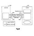
- the server 100includes an antenna 102 for communicating with remote clients 101 a, 101 b (for example portable computer devices), a transmission and reception module 103 , a message coder and decoder 104 (protocol stack) and a processing module 105 (query engine) for handling queries from clients 101 , for example regarding a particular user message status, accessing any such messages etc.
- Informationis accessed from a memory 106 which may be a data base storage module.
- the processor 105also communicates with a mail user agent (MUA) module 107 allowing user interface with the server 100 .
- the server 100is further in communication via the mail user agent 107 with a local and/or wide area network designated generally as 108 .
- MUAmail user agent
- the servicemay form part of, or be configured for connection with a telecommunications network or a computer network, for example the “Internet”.
- Each client 101 a, 101 bincludes various modules common with the server together with further modules specific to the needs of the client.
- the client 101includes an antenna 109 for communication with the server and a transmitting/receiving module 110 communicating with a message coder and decoder 111 .
- the module 110will include the hardware necessary for carrying out the transmitting/receiving steps but it will be recognized that at least some of the functions provided by the module will be capable of being provided in software. Indeed, generally, reference to modules need not be to dedicated hardware but extends to programmed or programmable software arranged to emulate hardware performance.
- the message coder and decoder 111interacts with the mail user agent 112 providing user interface.
- the mail user agent 112communicates with a local data storage device 113 and with optional modules such as a display driver 114 and/or a sound driver 115 (see client 101 a ).
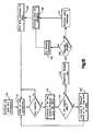
- FIG. 14displays the steps carried out by the user in a typical “client process”.
- the clientAuto-configures itself based on the resources (for example sound or graphics) available on the machine [step 120 ].
- the userlogs in and enters a password [ 121 ] and a connection is established between the client and the server [ 122 ] at which stage information entered during the log-in and password process is sent to the server for verification [ 123 ]. If, however, the server is not ready for communication then the procedure is exited [ 124 ] and must be recommended at step 120 or step 121 .
- the processAfter the user status is queried [ 123 ], if the user or password is unknown to the server the process returns to step [ 121 ] and the log-in and password procedure is re-initiated. Otherwise the options available to the user are retrieved [ 125 ] in steps discussed in more detail with reference to FIG. 15 and displayed as headers to the user [ 126 ]. The user then enters his selection [ 127 ] and the selection type is determined [ 128 ].
- the clientassesses whether the user wishes to view a message [ 129 ] and if so retrieves the selected message from the server [ 130 ] in a series of steps described in more detail below with reference to FIG. 15 .
- the clientdetermines the message type, for example audio or visual [ 131 ] and dependent on the message type either displays the text [ 132 ] or plays the sound [ 133 ].
- the clientthen returns to step [ 127 ] and awaits a further user selection.
- step [ 129 ]If at step [ 129 ] the user indicates that it is not desired to view a message then a message is created [ 134 ], recorded [ 135 ], the data of the message is packaged appropriately for transport [ 136 ], for example by the protocol stack 111 shown in FIG. 13, and is sent to the server [ 137 ] by the transmitter 110 and antenna 109 . The client then returns to step [ 127 ] and awaits a further user selection.
- the client machineincludes suitable input means, for example a keypad and display means for example an LCD display for the entry of user selection choices, message information and for the display of messages.
- suitable input meansfor example a keypad and display means for example an LCD display for the entry of user selection choices, message information and for the display of messages.
- a speaker and microphonemay be provided for the recordal and playback of audio messages.
- a portable computer devicesuch as that shown in FIG. 9 may, for example, be used as the client 101 . In that case, auto-configuration of the client is carried out partially in dependence on the type of module 22 inserted into the main body 21 of the portable computer device 20 .
- step [ 140 ]the server operates as a continuous process but, in order to save system resources is mostly in a stand-by mode where it simply listens to the local network. Accordingly in step [ 140 ], on initiation, an open end connection is established and the server monitors the connection [ 141 ]. If any queries are received [ 142 ] the server proceeds to the subsequent steps but otherwise continues to monitor the connection [ 141 ]. On reception of a query the server “wakes-up”, interprets the query to establish which of the internal modules of the server is designated [ 143 ] (for example data base storage 106 or mail user agent 107 ) and if the request is valid [ 144 ] the request type is determined [ 145 ].
- [ 143 ]for example data base storage 106 or mail user agent 107
- the requestmay be a HEADER which is sent to the client to present user message headers (corresponding to steps [ 125 ] and [ 126 ] shown in FIG. 14 ); accordingly at the request for a header [ 146 ] appropriate information is retrieved [ 147 ], is packaged for transport [ 148 ] for example at modules 104 , 103 of the server and is sent to the client [ 149 ].
- the serverthen returns to monitoring mode [ 141 ] listening to the connection with the remainder of the network.
- the serverretrieves any user messages [ 147 ] that are stored in respect of the identified user (for example on the basis of the log-in or password information entered at the client) and the data is packaged and sent as described above in relation to steps [ 148 , 149 ]. The system then returns to monitoring mode [ 141 ].
- steps [ 142 - 147 ]are carried out by the query engine 105 of the server, user message data being retrieved from the memory device 106 of the server.
- step [ 144 ]the request is not valid then the user and request are logged and an error message is sent back to the client [ 151 ]. The system then returns to monitoring mode [ 141 ].
- the system described aboverequires far less data storage on the client terminal/computer and thus is particularly (although not exclusively) suitable for hand-held computers with basic network capabilities.
- the systemthus resolves the problem of mail box locations as well as releasing the hand-held host and the data storage and retrieval responsibility by treating the mail delivery service as two cooperative and independent processors that communicate with each other using basic network protocols.
- the distributed mail delivery serviceuses the underlying network to actively present enquiries to the server regarding the message status relating to a particular user, rather than using a directory structure and relying on a file system. Because all enquiries are directed to one server, multiple connections for a single user can be identified and refused, the server is the only point of connection to external entities, offering a more secure delivery system and the server offers a view of the mail delivery service to the end user which is independent of the actual matter stored by the server.
- clientsare relieved of the responsibility of storing or directly retrieving any of the actual data.
- Messagesare delivered via the network on a demand basis, that is when required by the user, and the client portion of the distributed mail delivery service simply translates user requests into a series of commands which are forwarded to the server in the form of queries. If the quieries are validated the server returns the necessary data to a client in response to the queries.
- the servermay be initially decided that the server should store messages using a simple mail box scheme, but if the capacity or speed or efficiency of the system subsequently needs to be enhanced as a result of the increased burden placed on it by an increasing number of users and messages, the server can revert to using a complete database management system. Any such modifications will, however, remain hidden from the client portion and the client portion can effectively remain unaware of the underlying structures of the server indefinitely.
- the client portionmay be modified for example to move from a character-based user interface to a graphical-type interface in which case the server may remain unaware of the modifications as the basic data query and exchange mechanism is unchanged, the server remaining unconcerned about the manner of data presentation at the client portion.
- the client portionmay run on a PC compatible platform although it could be ported very simply to other platforms.
- the servercan operate on UNIX or DOS platforms.
- the clientrequires less than 256 bytes of local storage.
- the proposed delivery systemoffers multiple advantages over current mail box schemes, providing flexible and independent modules which are simpler to maintain and modify and which offers a generic mechanism by which data transfers can be implemented over data networks. As it is a distributed system it does not require the presence of a network file system and simply relies on local storage.
- each local networkfor dealing with the clients within a local network and also for communicating with other serves on other local networks the roaming capabilities of the system are enhanced.
- the distribution of mail processing between the various local networksis in contrast to the centralized hub system in conventional mail delivery systems and allows simplified and accelerated mail processing and transfer in combination with a roaming portable computer.
- Part 1“Symbol” Terminal Emulator Program (STEP) and pen-based mobile units/terminals.
- Symbol (a Trade Mark) terminal emulator programis a tool used to format applications for pen-based mobile units such as the mobile unit 21 shown in FIG. 9 .
- the STEPresides in the mobile units 21 and works with an enabler development system 160 on a host computer 162 to execute a predefined set of commands set from the host computer 162 .
- the enable development system 160includes an enabler server 164 , an enabler application program interface 166 and a timer 168 .
- the enabler development system 160receives input from the Spectrum24 access point unit 170 .
- the host computer 162is controlled by a terminal 172 to run host applications 174 .
- the STEPprovides the mobile units 21 with the interface and logic functions necessary to communicate over the radio network, and controls all input, output and display functions at the mobile unit level, including keyboards, displays, scanners and peripherals, and printer support.
- the STEPprovides commands that allow the administrator to create a selection of data entry fields for the mobile unit operator. For example, these commands would permit the operator to: (a) enter data from a keyboard and scan bar codes; (b) send multiple messages to the host in the same transaction; and (c) control the type of data entered and validate entered data. Further, for display purposes STEP allows the administration to (a) display data at any location on the mobile unit screen; (b) clear the entire mobile unit screen or clear a single line; (c) save and restore the mobile unit screen; and (d) control the backlighting feature to view the screen in the dark.
- the STEPacts as a power manager to reduce demands on the batteries in the mobile units 21 , enabling them to operate longer between charges and extending their overall life.
- formscan be created and displayed on the display screen 23 (shown in FIG. 9 ).
- Formscan include messages, prompts and data entry fields. This permits an operator to recall a stored form for execution on the mobile unit 21 ; repeat the execution of stored from for on-line batch processing; and erase all stored forms and determine the date and time of the last form definition.
- the STEP enabled mobile units 21allow the host computer 162 to read data files stored in the unit 21 ; sound the mobile unit's 21 alarm; interrupt mobile unit 21 input activity; and log off the mobile unit 21 from the host computer 162 . This allows the operator to use the mobile unit 21 to collect data without being logged on to the host computer 162 ; set and save system parameters; download files from the host computer 162 to the memory in the mobile unit 21 ; and perform other maintenance tasks.
- FIG. 17illustrates a typical conventional flow chart of the actions taken by the access point 170 when it receives a packet of data from he mobile unit 21 on the wireless network. If the packet is a registration packet, determined at step 200 , then the access point 170 processes the information carried by the packet at step 214 . The type of association is determined by examining the IP address of the mobile unit's 21 home access point and does the control message exchanges accordingly at steps 216 and 226 . If the packet is not a registration packet, as determined by step 200 , then the packet is decapsulated at step 202 .
- the short term address mapping tables (ST-AMT) of the access point 170has an entry of the packet's source MAC address, determined at step 204 , then the packet has originated from the mobile unit 21 that is away from its home stationary data link (SDL) network and processing passes to step 218 .
- the access point 170encapsulated the packet within a UDP packet with the IP destination address set to that of the mobile unit's 21 home access point.
- the access point 170encapsulates the packet within an UDP packet with the IP destination address set to the destination mobile unit's local access point.
- the packet's destination MAC addressis a broadcast address, determined at step 208 , then the packet if forwarded at step 222 on its wired and wireless interfaces. If the destination MAC address in the packet appears in the access point's mobile host table (MHT), determined at step 210 , then the packet is encapsulated within a wireless link layer packet and forwarded on the wireless interface at step 224 . Otherwise, the packet is forwarded on its wired interface at step 212 .
- MHTmobile host table
- Part 2Assigning domains and IP addresses to said pen-based mobile units 21 .
- the following embodiments of the present inventiondeal with assigning domains and IP addresses to the mobile units 21 to operate in a wireless LAN technology, such as the previously discussed Spectrum One and Spectrum24 systems.
- the domains and IP addressesare hard coded.
- the hard coded embodimentinvolves setting the domain and IP address of the mobile unit 21 in the configuration files associated with the Spectrum24 drivers and protocol stacks.
- the hard coded embodimentprovides a relatively simple implementation of domain and IP address assignment for Spectrum24 network installations when only a few mobile units 21 are used that always use the same APG on the same network.
- a high degree of securityis provided since the ability to detect and assign domain and IP addresses are available only in the configuration area, not in the operational area.
- each mobile unit 21ensures that the domain and IP address information are non-volatile. This insures that even cold booting the mobile unit 21 will not require configuration. All the access points 170 in the target APG can be configured to use the hard coded domain.
- the servercan be set up to reserve permanently (without any timeout) the hard coded IP addresses for use by each hard coded mobile unit 21 .
- Another embodiment of the present inventioninvolves the application-selection of domains and IP addresses.
- This embodimentis suitable for situations where a system administrator manually configures the mobile units 21 before their use by operators by setting the domain and IP address.
- a system administratormanually configures the mobile units 21 before their use by operators by setting the domain and IP address.
- mobile units 21are the only nodes on the network or when the system administrator set domains and IP addresses by referring to a master list maintained on a network server the application-selection system is advantageous.
- the application-selection methodallows for the dynamic adjustment of domain and IP addresses under application control across APGs and networks.
- a further embodiment of the present inventioninvolves the access points-assignment of domains and server-assignment of IP addresses. This method is suitable when the manual assignment of domains and IP addresses is impractical due to many mobile units 21 or due to the complexity of the network.
- AP-assignment of domainsrequires configuring access points 170 to allow for an automatic configuration.
- access point 170 access control list (ACL) featuressecurity can be enhanced by giving the access points 170 a list of the MAC-layer addresses of all the mobile units 21 allowed. This list can be larger than the number of mobile units 21 actually being serviced at any given time, allowing the timesharing of the capacity of the access point 170 among a large set of intermittent use mobile units 21 .
- ACLaccess control list
- Server-assignment of IP addressesrequires the existence of a mechanism within the protocol stack, supported by services and utilities in both the server and the mobile unit 21 , to allow dynamic allocation of IP addresses.
- BOOTP and DHCPare two common mechanisms for dynamic allocation.
- BOOTPworks by having a file on the server for each possible mobile unit 21 , selected by the mobile unit's 21 unique MAC-layer address, that provides the IP address to be used for the mobile unit 21 .
- DHCPworks by having a database on the server that records the IP addresses that are in use (by MAC-layer address) and the IP addresses that are available for dynamic assignment.
- the databaseis searched for the MAC-layer address. If an IP address is already allocated to this mobile unit 21 , the it is simply returned. If no IP address is allocated to the mobile unit 21 , and one is available for dynamic assignment, it is allocated to the mobile unit 21 , recorded in the database and assigned to the mobile unit's MAC-layer address, and returned to the mobile unit 21 .
- the DHCP servercan set to timeout when a dynamically assigned IP address has not been used for some time and return it to the available list or to keep IP addresses permanently assigned once allocated to a mobile unit 21 .
- the domains and IP addressescan be stored in volatile storage, but would need to be reentered following a reboot. However, the necessary address information can be stored onboard the flash of the mobile unit 21 , or on the Spectrum24 adapter card, or on RAM disks or PCMCIA storage cards.
- the AP/server-assignment methodsprovide the ability to program ACL information via a personal computer attached to the same hardwired router as the access point 170 . Further, the AP/server-assignment methods allow for automatic assignment of complying domain and IP addresses as needed, and allow mobility across APGs and networks.
- the inventionaddresses the problem of the necessity of a specialized program for parsing and interpreting high density data records embedded in bar code labels.
- itis proposed to distribute not only the bar code data on a high density label, but also information describing how to create an interface capable of reading the data from the data record label.
- the mobile unitincludes a reader or Browser for scanning a high density bar code label that contains a program script such as HTML, VB script or a specialized compressed version of either.
- the scriptis parsed and interpreted by Browser which constructs a user interface at run time and presents it to the user.
- the userinteracts with the interface by scanning data labels and interacting with any of the program's controls presented to the user to properly process the data.
- a new data or interface levelmay be printed by the user that can be applied to the object being processed. It will be appreciated that, as bar code label densities increase, the capability of storing the actual interface and the data record in a single bar code label will appear.
- FIG. 18shows the system of the invention in more detail.
- the systemincludes a Browser 300 to which bar code information 301 is input.
- An interface 302is constructed at run time and an interface control 303 is provided.
- the Browser 300further includes a bar code acquisition engine 304 , a parsing engine 305 , a printing engine 306 with a printed data interface 307 and a communications engine 308 with a communications input/output interface 309 .
- the userinteracts with the interface via a further interface 310 .
- the shipper of the goodscan distribute a program script label with the goods that is read by the receiver's Browser.
- the program script label shipped with the goodscontains the information required to allow the Browser to create an interface at run-time to read and process the data for the container of goods shipped.
- Logistical systemsbenefit greatly from a system such as this, because unidentified materials in the field can quickly be identified and processed by any unit containing the Browser.
- any computer system equipped with a general purpose interface reader applicationcan create an interface “on-the-fly” that is capable of reading processing information on the accompanying data record labels.
- a bar code scanning OLE (Object Linking and Embedding) COM (Component Object Model) objectfor communicating commands and bar code data over a wireless link.
- OLE automationObject Linking and Embedding
- the in-process OLE automation objectcontrols a bar code scanning device over a wireless link on a remote client.
- the remote deviceenables a bar code reader and collects the bar code information, returning the data over the wireless link to the OLE automation object.
- OLE controlsare re-usable software components designed to work in containers that support OLE 2.0.
- OLE controlsare more powerful and more flexible than previous systems such as VBX Custom Controls in particular as, unlike the VBX Custom Controls that they are replacing OLE controls support 32 bit environments and are not limited to Microsoft Visual Basic (Trade Marks).
- OLE controlsare designed to work in any container that supports OLE 2.0 including not only Visual Basic 4.0 and beyond but also OLE-enabled container applications such as Microsoft Office (Trade Mark). Additionally OLE controls work in third-party OLE-enabled applications in development tools.
- OLE architectureenables different software objects to communicate to each other using a binary interface mechanism. This allows software objects to be developed separate from each other and bind very late at run time.
- the software interfaceis a contract between the container and the control on how the two software objects will interact and exchange information.
- FIG. 19shows the general mechanism between a control 401 and its container 402 . As can be seen the mechanism includes standard compound document interfaces 403 and additional control interfaces 404 , each comprising multiple interfaces.
- the scanning controlappears to become a seamless part of the container's environment.
- the two objectscommunicate and integrate with each other.
- the scanning control 401communicates over a wireless link 410 with a remote computing client 411 to control the bar code reading device 412 .
- the scanning control 401sends commands over the wireless link 410 by creating separate threads of execution 413 a to 413 d that send, receive and synchronize bar code reader transactions over the wireless link.
- the OLE container 402 and control 401communicate via lines 414 a to 414 f.
- the OLE controlincludes a main control thread 415 which communicates with the OLE container 401 via lines 414 a, 414 b and with a first transaction thread A 413 a via a line 416 .
- Each of the transaction threads 413 a to 413 dcommunicate along a respective line 414 c to 414 f with the OLE container 402 .
- Each of the threadsalso outputs through a respective first line 417 a to 417 d to a transaction start dispatch function 418 and receives an input via a respective second line 419 a to 419 d from a transaction complete dispatch function 420 .
- the transaction start dispatch function 418communicates with a transport layer 421 in the remote client 411 via a line 422 and a transaction complete dispatch function 420 receives input from the transport layer 421 via a line 423 .
- the remote client 411includes a corresponding transport layer 424 which outputs via a line 425 to a data arrival handler 426 and receives an input via line 427 from a command complete handler 428 .
- the data arrival handler 426outputs via line 429 to a bar code device driver 430 and the command complete handler receives an input 431 from the bar code device driver 430 .
- the bar code device driver 430communicates with the scanning hardware such as a bar code reader 412 via a line 432 .
- the inventioncomprises a significant development over previous architectures comprising implementation of a local bar code scanner resident on a machine running a COM object.
- the architecture of the inventionallows control of the scanner through the wireless interface.
- DCOMdistributed component object model architecture
- the interfaces between the control container and the control itselfare binary and can be implemented by the operating system as Remote Procedure Calls (RPC's).
- RPCRemote Procedure Calls
- the OLE controlcan be implemented as an Active-X control to control devices over an Internet or Intranet link.
- This technologyallows Web authors and developers to create a new generation of interactive Web pager and applications, for example Microsoft Internet Explorer 3.0 (Trade Mark).
- This implementationis of particular benefit in proposed systems whereby users will wish to integrate bar code scanning capabilities into their Intranet/Internet-enabled applications.
- the Intranetarises from the application of Internet technology to provide industrial strength mission critical applications to users within an organization on an isolated LAN (Local Area Network) rather than for external connection to the global internet.
- Single function handheld computing terminalscan then be built that connects to the LAN and execute predetermined applications to reduce significantly the cost per client when installing a network system.
- mission critical applicationsreside on the server, eliminating the cost of application deployment and lowering the cost of terminal configuration.
- the data collectedis transmitted and saved on the server so little or no local data storage is needed on the handheld terminal. It will be seen, therefore, that such a system provides an ideal forum for the OLE scanning control object discussed above.
- FIG. 21there is shown a collection of items 1300 which need to be returned to the vendor for a variety of reasons, for example incorrect shipment (wrong color, size item number) damage in transit, to be returned for credit etc.
- Each item 1300carries a bar code symbol 1310 .
- the individual items 1300are to be placed in a container or returns box 1340 in which they will be shipped back to the supplier or vendor.
- each bar code scannerincorporates a printer 562 , a keyboard 562 ′, 1116 for entering textural information, and a host computer 560 which incorporates a computer memory for storing details of the indicia that have been scanned, and the information entered via the keyboard.
- the host computeralso incorporates a CPU having appropriate software.
- the retailerfirst (at step 1360 ) uses the bar code reader to scan and read the bar code 1310 on the product 1300 . He then, at step 1370 , enters on the keyboard 562 ′, 1116 the reason for the return, or alternatively as required by the supplier a returns number.
- the bar code details and the reasonsare automatically added to a database maintained within the memory of the host computer 560 . It will of course be appreciated that in an alternative embodiment (not shown) the user could be required to enter the details on the keyboard before, rather than after, scanning the bar code symbol. In either case, once the item 1300 has been scanned it is then placed into the large container 1340 .
- step 1390the process continues at step 1390 , with steps 1360 to 1380 being repeated if further items are to be shipped.
- the retailerhas finished, he presses a “done” key on the keyboard, at step 1400 , to advise the host computer that there are no additional items to be added.
- the host computer 560than encodes the database entries for PDF printing, and at step 1420 prints out a PDF bar code label.
- the PDF label, 1320contains a listing of all the items in the container 1340 and the reasons for their return.
- the labelis preferably self-adhesive, and the vendor merely secures it to the outside of the container before shipping.
- the printer 562could print the PDF bar code directly onto the surface of the container 1340 .
- a further label 1330showing the address of the consignment, may be printed out automatically. The vendor also secures that to the outside of the container. The container can then be shipped.
- the supplierOn receipt of the container, the supplier simply reads the PDF label 1320 to determine which items are in the box, and the reasons for their return. Where the bar code incorporates return codes, the supplier can simply and easily determine whether the retailer has authorization to return those particular products.
- the labelmay, in addition, contain encoded information identifying the particular retainer in question.
- the bar code symbol 1320is desirably a PDF symbol, which is automatically produced by the software contained within the host computer 560 . Details of the encoding method used by the software, which would enable a skilled man to deviate appropriate software, are described in the above-referenced US patent in common ownership with the present application.
- FIGS. 23 to 26illustrate various exemplary embodiments of the scanner/printer assembly.
- reference numeral 510generally identifies a lightweight (less than 1 lb), narrow bodied, streamlined, hand-held, fully-portable, easy-to-manipulate, non-arm and wrist-fatiguing, scanning head supportable entirely by an operator for use in a scanning system operative for reading, scanning and/or analyzing symbols and aimable, both prior to and during reading thereof, by the operator at the symbol, each symbol in its turn.
- symbolas used herein is intended to cover indicia composed of parts having different light-reflective properties.
- the indiciamay be industrial symbols, e.g. Code 30 , Codebar, Interleaved 2 or 5 , etc., or the omnipresent Universal Product Code (UPC) bar code symbol.
- the indiciamay also be composed of alphabetic and/or numeric characters.
- the head 510includes a generally gun-shaped housing having a handle portion 512 or generally rectangular cross-section, and a generally horizontally-elongated narrow-bodies barrel or body portion 514 .
- the dimensions and overall size of the handle portion 512are such that the head 510 can conveniently fit and be held in the operator's hand.
- the body and handle portionsare constituted of a lightweight resilient, shock-resistant, self-supporting material such as a synthetic plastic material.
- the plastic housingis preferably injection-molded and forms a thin, hollow shell whose interior space measures less than a volume on the order of 50 cu.in.
- the body portion 514has a front wall 516 , a rear wall 518 spaced rearwardly of the front wall, a top wall 520 , a bottom wall 522 below the top wall, and a pair of opposed side walls 524 , 526 that lie in mutual parallelism between the top and bottom walls.
- a manually-actuable, and preferably depressible, trigger 528is mounted for pivoting movement about a pivot axis on the head in a forwardly-facing region where the handle and body portions meet and where the operator's forefinger normally lies when the operator grips the handle portion in the intended position of use.
- a plurality of componentsare mounted in the head and, as explained below, at least some of them are actuated by the trigger 528 , either directly or indirectly, by means of a control microprocessor 530 .
- One of the head componentsis an actuable light source e.g. a semiconductor laser diode 532 or a light emitting diode, operative, when actuated by the trigger 528 , for propagating and generating an incident light beam.
- the light beamis highly divergent, is non-radially symmetrical, is generally oval in cross-section, and has a wavelength above 7000 Angstrom units.
- the laser diode 532requires a low voltage, e.g.
- a battery 534which may be provided within the handle portion 512 or by a rechargeable battery pack accessory detachably mounted on the head, or by a power conductor in a cable connected to the head from an external power supply.
- An optical assemblyincluding a half-silvered mirror 537 and an optical train 538 , is mounted in the head, and is adjustably positioned relative to the diode 532 for optically modifying and directing the incident laser beam along a first optical path toward a reference plane which is located exteriorly of the head forwardly of the front wall 516 and which lies generally perpendicular to the longitudinal direction along which the incident laser beam propagates.
- a symbol to be readis located at the vicinity of the reference plane, either at, or at one side, or at an opposite side, of the reference plane, that is, anywhere within the depth of focus or field of the optically-modified incident laser beam.
- the depth of focus or fieldis also known as the working distance in which the symbols can be read.
- the incident laser beamreflects off each symbol in many directions, and that portion of the reflected laser light which travels away from the symbol back toward the head is known herein as the returning portion.
- the scanning mirror 540is mounted on a scanning component, preferably a high-spaced scanner motor 546 of the type shown and described in U.S. Pat. No. 4,387,297, the entire contents of which are incorporated herein by reference.
- the motor 546has an output shaft on which a support bracket is fixedly mounted.
- the scanning mirror 540is fixedly mounted on the bracket and is driven in alternate circumferential directions over art lengths of any desired size, typically less than 360°, and at a rate of speed on the order of a plurality of oscillations per second.
- the scanning mirror 540 and the shaftare reciprocally and repetitively oscillated so that the scanning mirror repetitively sweeps the incident laser beam impinging on the mirror through an angular distance or arc length at the reference plane of about 32° and at a rate of about 20 scans or 40 oscillations per second.
- the returning portion of the reflected laser lighthas a variable light intensity due to the different light-reflective properties of the various parts that comprise the symbol over the symbol during the scan.
- the returning portion of the reflected laser lightis collected in the direction of arrow 548 by a generally concave spherical portion of the mirror 540 .
- the generally planar mirror portionis integrally attached to the generally spherical mirror portion of the mirror 540 .
- the spherical portionreflects the collected light through the optical train 538 , the half-silvered mirror 537 , and to a sensor means, e.g. a photosensor 550 .
- the photosensor 550preferably a photodiode, detects the variable intensity of the collected laser light over a field of view which extends along, and preferably beyond, the scan and generates an electrical analog signal indicative of the detected variable light intensity.
- a signal processing means 552mounted on a circuit board 554 , and operative for processing the analog electrical signal generated by the photodiode 550 into a digitized video signal. Data descriptive of the symbol can be derived from the video signal. Suitable signal processing circuitry for this purpose was described in U.S. Pat. No. 4,251,798.
- Other components within the headinclude drive circuitry for the motor 546 , an aiming light controller in the event that the laser diode 532 generates a laser beam which is not readily visible to the human eye, and a voltage converter for converting incoming voltage, e.g. from the battery 534 , to a regulated voltage suitable for energizing the laser diode 532 .
- a decode/control means 556operative for decoding the digitized video signal to a digitized decoded signal from which the desired data descriptive of the symbol is obtained in accordance with an algorithm contained in a software control program in the microprocessor 530 .
- the decode-control meansincludes a PROM for holding the control program, and an RAM for temporary data storage.
- the decode/control means 556together with the micro-processor, determine when a successful decoding of the symbol has been obtained, and also terminates the reading of the symbol upon determination of the successful decoding thereof. The initiation of the reading is caused by depression of the trigger 528 .
- the decode/control meansalso includes control circuitry for controlling the actuation of the actuatable components in the head, namely, the laser diode 532 , the photodiode 550 , the motor 546 , and all the other electronic subcircuits therein, as initiated by the trigger, as well as for communicating with the user that the reading has been automatically terminated as, for example, by sending a control signal to an indicator lamp 558 to illuminate the same or by energizing a buzzer or beeper.
- the decoded signalis either conducted along a conductor within a cable interconnected between the head and a remote host computer 560 , or is transmitted by radio wave from the head to the computer 560 by means of antenna 536 .
- the computer 560serves essentially as a large data base, may be an in-store processor, stores the decoded signal, and provides information related to the decoded signal. It includes a CPU 560 ′ and a memory 560 ′′.
- the host computerin accordance with this invention, can provide retail price information on an updated basis corresponding to the products identified by their decoded symbols.
- the host computercan advantageously be incorporated in a portable terminal, or in a stationary terminal such as a cash register.
- the data basecan be incorporated in a portable housing held in one's other hand, or supported on the operator's person, for example, suspended from a belt or shoulder strap, in a field-portable application.
- a keyboard 562 ′may advantageously be provided on the head for entering data relating to the symbol and/or the product bearing the same.
- the keyboardincludes a “done” key 562 ′′ by which the user tells the host computer 60 that there are no more items to be scanned.
- a display 64is also conveniently mounted adjacent the keyboard 562 ′ on the top wall 520 of the head, and is operative for displaying information relating to the symbol and/or the product bearing the same.
- each product 1300 bearing a label imprinted with a symbol 1310is identified by scanning the symbol with the hand-held scanner head 510 in the manner depicted in FIG. 24 .
- the printing of the PDF code symbol 1320is performed by a printer 562 that is either incorporated in the hand-held head 510 (see FIG. 21) or held in one's other hand, or worn on one's person (see FIG. 22 ), or mounted on a nearby support surface such as a countertop, or incorporated in another component such as a scale or cash register, as described below.
- the printerincludes a thermal printhead 561 operative for thermally imprinting graphical markings on a journaled roll 563 of paper labels, each print label being torn off the roll by being urged against tear-off edge 565 at the front of the head 510 .
- the labelpreferably has a pressure-adhesive backing so that it can be applied directly on the container 340 .
- FIG. 25illustrates an alternative printer/scanner arrangement which can be used with the present invention.
- the assemblycomprises a portable data terminal 1100 having a keyboard 1102 for data entry, and a screen 1104 . Attached to the portable data terminal are an integrated printer 1106 and a separate bar code reader 1108 .
- FIG. 26An alternative printer/scanner arrangement is shown in FIG. 26 .
- thiscomprises a portable data terminal 1100 ′, having a keyboard 1102 ′, and a screen 1104 ′.
- the terminalincorporates an integral scanner head 1110 .
- Attached to the terminalis a separate printer 1112 .
Landscapes
- Engineering & Computer Science (AREA)
- Theoretical Computer Science (AREA)
- Physics & Mathematics (AREA)
- General Engineering & Computer Science (AREA)
- General Physics & Mathematics (AREA)
- Computer Hardware Design (AREA)
- Human Computer Interaction (AREA)
- Databases & Information Systems (AREA)
- Signal Processing (AREA)
- Computer Networks & Wireless Communication (AREA)
- Data Mining & Analysis (AREA)
- Mathematical Physics (AREA)
- Electromagnetism (AREA)
- Power Engineering (AREA)
- Toxicology (AREA)
- Artificial Intelligence (AREA)
- Computer Vision & Pattern Recognition (AREA)
- Multimedia (AREA)
- General Health & Medical Sciences (AREA)
- Health & Medical Sciences (AREA)
- Information Transfer Between Computers (AREA)
Abstract
Description
Claims (35)
Priority Applications (5)
| Application Number | Priority Date | Filing Date | Title |
|---|---|---|---|
| US09/570,961US6714969B1 (en) | 1995-11-17 | 2000-05-15 | Mobile terminal with integrated host application software |
| US09/814,879US6920637B2 (en) | 1995-11-17 | 2001-03-22 | Method and apparatus for implementing alerts on a browser running on a portable handheld device |
| US10/838,007US20050223389A1 (en) | 1995-11-17 | 2004-05-03 | Method and system for remote browsing of computer files using a bar code reader |
| US11/146,547US7577745B2 (en) | 1995-11-17 | 2005-06-06 | Method and apparatus for implementing alerts on a browser running on a portable handheld device |
| US12/499,192US7975067B2 (en) | 1995-11-17 | 2009-07-08 | Method and apparatus for implementing alerts on a browser running on a portable handheld device |
Applications Claiming Priority (5)
| Application Number | Priority Date | Filing Date | Title |
|---|---|---|---|
| US687295P | 1995-11-17 | 1995-11-17 | |
| US69126396A | 1996-08-02 | 1996-08-02 | |
| US91660597A | 1997-08-22 | 1997-08-22 | |
| US09/520,929US6507864B1 (en) | 1996-08-02 | 2000-03-08 | Client-server software for controlling data collection device from host computer |
| US09/570,961US6714969B1 (en) | 1995-11-17 | 2000-05-15 | Mobile terminal with integrated host application software |
Related Parent Applications (1)
| Application Number | Title | Priority Date | Filing Date |
|---|---|---|---|
| US09/520,929DivisionUS6507864B1 (en) | 1995-11-17 | 2000-03-08 | Client-server software for controlling data collection device from host computer |
Related Child Applications (2)
| Application Number | Title | Priority Date | Filing Date |
|---|---|---|---|
| US09/814,879Continuation-In-PartUS6920637B2 (en) | 1995-11-17 | 2001-03-22 | Method and apparatus for implementing alerts on a browser running on a portable handheld device |
| US10/838,007ContinuationUS20050223389A1 (en) | 1995-11-17 | 2004-05-03 | Method and system for remote browsing of computer files using a bar code reader |
Publications (1)
| Publication Number | Publication Date |
|---|---|
| US6714969B1true US6714969B1 (en) | 2004-03-30 |
Family
ID=31999436
Family Applications (2)
| Application Number | Title | Priority Date | Filing Date |
|---|---|---|---|
| US09/570,961Expired - LifetimeUS6714969B1 (en) | 1995-11-17 | 2000-05-15 | Mobile terminal with integrated host application software |
| US10/838,007AbandonedUS20050223389A1 (en) | 1995-11-17 | 2004-05-03 | Method and system for remote browsing of computer files using a bar code reader |
Family Applications After (1)
| Application Number | Title | Priority Date | Filing Date |
|---|---|---|---|
| US10/838,007AbandonedUS20050223389A1 (en) | 1995-11-17 | 2004-05-03 | Method and system for remote browsing of computer files using a bar code reader |
Country Status (1)
| Country | Link |
|---|---|
| US (2) | US6714969B1 (en) |
Cited By (106)
| Publication number | Priority date | Publication date | Assignee | Title |
|---|---|---|---|---|
| US20020052965A1 (en)* | 2000-10-27 | 2002-05-02 | Dowling Eric Morgan | Negotiated wireless peripheral security systems |
| US20020062385A1 (en)* | 2000-10-27 | 2002-05-23 | Dowling Eric Morgan | Negotiated wireless peripheral systems |
| US20020087601A1 (en)* | 2000-12-29 | 2002-07-04 | Anderson Eric C. | Client-server system for merging of metadata with images |
| US20020090132A1 (en)* | 2000-11-06 | 2002-07-11 | Boncyk Wayne C. | Image capture and identification system and process |
| US20020167916A1 (en)* | 2001-05-14 | 2002-11-14 | Clapper Edward O. | Processor-based shopping cart |
| US20030229472A1 (en)* | 2001-12-06 | 2003-12-11 | Kantzes Christopher P. | Field maintenance tool with improved device description communication and storage |
| US20040039458A1 (en)* | 2002-03-12 | 2004-02-26 | Mathiowetz Brad N. | Movable lead access member for handheld field maintenance tool |
| US20040111238A1 (en)* | 2002-12-05 | 2004-06-10 | Fisher-Rosemount Systems, Inc. | Method of adding software to a field maintenance tool |
| US20040186760A1 (en)* | 2003-03-17 | 2004-09-23 | Metzger Tracy Alan | System and method for sales and inventory reconciliation |
| US20040201363A1 (en)* | 2003-03-06 | 2004-10-14 | Fisher-Rosemount Systems, Inc. | Heat flow regulating cover for an electrical storage cell |
| US20040218326A1 (en)* | 2003-04-30 | 2004-11-04 | Joachim Duren | Intrinsically safe field maintenance tool with power islands |
| US20040227723A1 (en)* | 2003-05-16 | 2004-11-18 | Fisher-Rosemount Systems, Inc. | One-handed operation of a handheld field maintenance tool |
| US20040230327A1 (en)* | 2003-05-15 | 2004-11-18 | Fisher-Rosemount Systems, Inc. | Field maintenance tool with enhanced scripts |
| US20040228184A1 (en)* | 2003-05-16 | 2004-11-18 | Fisher-Rosemount Systems, Inc. | Physical memory handling for handheld field maintenance tools |
| US20040230821A1 (en)* | 2003-05-16 | 2004-11-18 | Mathiowetz Brad N. | Memory authentication for intrinsically safe field maintenance tools |
| US20040226385A1 (en)* | 2003-05-16 | 2004-11-18 | Mathiowetz Brad N. | Multipurpose utility mounting assembly for handheld field maintenance tool |
| US20050003839A1 (en)* | 2003-05-13 | 2005-01-06 | Tripp Jeffrey William | Decision influence data system |
| US20050085188A1 (en)* | 2003-10-17 | 2005-04-21 | Sharp Laboratories Of America, Inc. | Method for transferring data objects between portable devices |
| US20050169228A1 (en)* | 2000-10-27 | 2005-08-04 | Dowling Eric M. | Federated multiprotocol communication |
| US20050223389A1 (en)* | 1995-11-17 | 2005-10-06 | John Klein | Method and system for remote browsing of computer files using a bar code reader |
| US20050234851A1 (en)* | 2004-02-15 | 2005-10-20 | King Martin T | Automatic modification of web pages |
| US6990548B1 (en)* | 2000-06-15 | 2006-01-24 | Hewlett-Packard Development Company, L.P. | Methods and arrangements for configuring a printer over a wireless communication link using a wireless communication device |
| US20060085308A1 (en)* | 2003-03-17 | 2006-04-20 | Abanco International, Llc | System and method for sales and service reconciliation |
| US20060102759A1 (en)* | 2004-11-16 | 2006-05-18 | Delong Mark | Automated tracking and billing system for the application of asphalt release agents |
| US20060123010A1 (en)* | 2004-09-15 | 2006-06-08 | John Landry | System and method for managing data in a distributed computer system |
| US20060136629A1 (en)* | 2004-08-18 | 2006-06-22 | King Martin T | Scanner having connected and unconnected operational behaviors |
| US20060161393A1 (en)* | 2001-12-06 | 2006-07-20 | Martin Zielinski | Dual protocol handheld field maintenance tool with radio-frequency communication |
| US20060193278A1 (en)* | 1997-10-15 | 2006-08-31 | Wolfgang Theimer | Mobile telephone for Internet applications |
| US20060253338A1 (en)* | 2003-03-17 | 2006-11-09 | Metzger Tracy A | System for real-time sales and inventory reconciliation |
| WO2006023715A3 (en)* | 2004-08-18 | 2007-07-12 | Exbiblio Bv | Applying scanned information to identify content |
| US20070294741A1 (en)* | 1998-06-17 | 2007-12-20 | Yoshito Nejime | Broadcasting method and broadcast signal receiving apparatus |
| US7330896B1 (en)* | 1999-02-25 | 2008-02-12 | Nortel Networks Limited | Correlating data streams of different protocols |
| US20080195769A1 (en)* | 2007-01-26 | 2008-08-14 | Juraid Anwer | Method of identifying devices in mobile and desktop environments |
| US20080214172A1 (en)* | 2007-01-26 | 2008-09-04 | Juraid Anwer | Method of loading software in mobile and desktop environments |
| US20080284247A1 (en)* | 2007-05-18 | 2008-11-20 | Siemens Aktiengesellschaft | Method for operating a system of modular structure, in particular a process automation system |
| US20080296391A1 (en)* | 2007-05-25 | 2008-12-04 | Hewlett-Packard Development Company Lp | Modular marking apparatus and method |
| US20080313559A1 (en)* | 2007-06-13 | 2008-12-18 | Kulus Christian J | Functionality for handheld field maintenance tools |
| WO2009018021A1 (en)* | 2007-07-31 | 2009-02-05 | Palm, Inc. | Widget discovery in computing devices |
| US20090064190A1 (en)* | 2007-08-31 | 2009-03-05 | Mindy Pereira | Techniques for receiving event information |
| US20090061825A1 (en)* | 2007-08-31 | 2009-03-05 | Palm, Inc. | Techniques for group messaging on a mobile computing device |
| US20090089331A1 (en)* | 2007-04-04 | 2009-04-02 | Boaz Thomas L | Real-Time Method and System for Tracking Mail |
| EP1771784A4 (en)* | 2004-04-01 | 2009-05-06 | Exbiblio Bv | Triggering actions in response to optically or acoustically capturing keywords from a rendered document |
| EP1759282A4 (en)* | 2004-04-01 | 2009-05-06 | Exbiblio Bv | Data capture from rendered documents using handheld device |
| US20090157695A1 (en)* | 2007-08-10 | 2009-06-18 | Smiths Medical Md | Central Server for Medical Devices |
| US20090265423A1 (en)* | 2008-04-16 | 2009-10-22 | Aricent Inc. | Method and system of mobile application implementation on network server |
| EP1782230A4 (en)* | 2004-07-19 | 2009-11-04 | Exbiblio Bv | Automatic modification of web pages |
| US20090281935A1 (en)* | 1996-10-02 | 2009-11-12 | Nintendo Of America Inc. | Method and apparatus for efficient handling of product return transactions |
| US20100165401A1 (en)* | 2005-09-19 | 2010-07-01 | Silverbrook Research Pty Ltd | Mobile device for printing a security identification |
| US7812860B2 (en) | 2004-04-01 | 2010-10-12 | Exbiblio B.V. | Handheld device for capturing text from both a document printed on paper and a document displayed on a dynamic display device |
| US7823778B1 (en) | 2007-08-08 | 2010-11-02 | Cellco Partnership | Wireless inventory scanner system and method |
| US20110150292A1 (en)* | 2000-11-06 | 2011-06-23 | Boncyk Wayne C | Object Information Derived from Object Images |
| US7982904B2 (en) | 2005-09-19 | 2011-07-19 | Silverbrook Research Pty Ltd | Mobile telecommunications device for printing a competition form |
| US7990556B2 (en) | 2004-12-03 | 2011-08-02 | Google Inc. | Association of a portable scanner with input/output and storage devices |
| US20110211760A1 (en)* | 2000-11-06 | 2011-09-01 | Boncyk Wayne C | Image Capture and Identification System and Process |
| US8081849B2 (en) | 2004-12-03 | 2011-12-20 | Google Inc. | Portable scanning and memory device |
| US8146156B2 (en) | 2004-04-01 | 2012-03-27 | Google Inc. | Archive of text captures from rendered documents |
| US20120102155A1 (en)* | 2010-10-20 | 2012-04-26 | Samsung Electronics Co., Ltd. | Communication method for portable terminal |
| US8179563B2 (en) | 2004-08-23 | 2012-05-15 | Google Inc. | Portable scanning device |
| US8261094B2 (en) | 2004-04-19 | 2012-09-04 | Google Inc. | Secure data gathering from rendered documents |
| US8286858B2 (en) | 2005-09-19 | 2012-10-16 | Silverbrook Research Pty Ltd | Telephone having printer and sensor |
| US8290512B2 (en) | 2005-09-19 | 2012-10-16 | Silverbrook Research Pty Ltd | Mobile phone for printing and interacting with webpages |
| US8326038B2 (en) | 2000-11-06 | 2012-12-04 | Nant Holdings Ip, Llc | Object information derived from object images |
| US8346620B2 (en) | 2004-07-19 | 2013-01-01 | Google Inc. | Automatic modification of web pages |
| EP1741028A4 (en)* | 2004-04-12 | 2013-01-09 | Google Inc | Adding value to a rendered document |
| US8418055B2 (en) | 2009-02-18 | 2013-04-09 | Google Inc. | Identifying a document by performing spectral analysis on the contents of the document |
| US8442331B2 (en) | 2004-02-15 | 2013-05-14 | Google Inc. | Capturing text from rendered documents using supplemental information |
| US8447066B2 (en) | 2009-03-12 | 2013-05-21 | Google Inc. | Performing actions based on capturing information from rendered documents, such as documents under copyright |
| US8489624B2 (en) | 2004-05-17 | 2013-07-16 | Google, Inc. | Processing techniques for text capture from a rendered document |
| US20130232569A1 (en)* | 2011-03-09 | 2013-09-05 | Kabushiki Kaisha Toshiba | Information processing apparatus and display control method |
| US8600196B2 (en) | 2006-09-08 | 2013-12-03 | Google Inc. | Optical scanners, such as hand-held optical scanners |
| US8620083B2 (en) | 2004-12-03 | 2013-12-31 | Google Inc. | Method and system for character recognition |
| USD697067S1 (en)* | 2011-11-04 | 2014-01-07 | Datalogic Ip Tech S.R.L. | Portable terminal |
| US8707163B2 (en)* | 2011-10-04 | 2014-04-22 | Wesley John Boudville | Transmitting and receiving data via barcodes through a cellphone for privacy and anonymity |
| US8713418B2 (en) | 2004-04-12 | 2014-04-29 | Google Inc. | Adding value to a rendered document |
| US8768717B2 (en)* | 2000-08-02 | 2014-07-01 | Smiths Medical Asd, Inc. | Processing program data for medical pumps |
| US8781228B2 (en) | 2004-04-01 | 2014-07-15 | Google Inc. | Triggering actions in response to optically or acoustically capturing keywords from a rendered document |
| US8788432B2 (en) | 1996-10-02 | 2014-07-22 | Nintendo Of America Inc. | Method and apparatus for efficient handling of product return transactions |
| US8824738B2 (en) | 2000-11-06 | 2014-09-02 | Nant Holdings Ip, Llc | Data capture and identification system and process |
| US8874504B2 (en) | 2004-12-03 | 2014-10-28 | Google Inc. | Processing techniques for visual capture data from a rendered document |
| USD716307S1 (en) | 2013-05-16 | 2014-10-28 | Datalogic Ip Tech S.R.L. | Portable terminal |
| US8892495B2 (en) | 1991-12-23 | 2014-11-18 | Blanding Hovenweep, Llc | Adaptive pattern recognition based controller apparatus and method and human-interface therefore |
| US8954336B2 (en) | 2004-02-23 | 2015-02-10 | Smiths Medical Asd, Inc. | Server for medical device |
| US8990235B2 (en) | 2009-03-12 | 2015-03-24 | Google Inc. | Automatically providing content associated with captured information, such as information captured in real-time |
| US9008447B2 (en) | 2004-04-01 | 2015-04-14 | Google Inc. | Method and system for character recognition |
| US9081799B2 (en) | 2009-12-04 | 2015-07-14 | Google Inc. | Using gestalt information to identify locations in printed information |
| US9116890B2 (en) | 2004-04-01 | 2015-08-25 | Google Inc. | Triggering actions in response to optically or acoustically capturing keywords from a rendered document |
| US9143638B2 (en) | 2004-04-01 | 2015-09-22 | Google Inc. | Data capture from rendered documents using handheld device |
| US9268852B2 (en) | 2004-02-15 | 2016-02-23 | Google Inc. | Search engines and systems with handheld document data capture devices |
| US9310892B2 (en) | 2000-11-06 | 2016-04-12 | Nant Holdings Ip, Llc | Object information derived from object images |
| US9323784B2 (en) | 2009-12-09 | 2016-04-26 | Google Inc. | Image search using text-based elements within the contents of images |
| US9535563B2 (en) | 1999-02-01 | 2017-01-03 | Blanding Hovenweep, Llc | Internet appliance system and method |
| US20170041797A1 (en)* | 2009-10-15 | 2017-02-09 | At&T Intellectual Property I, L.P. | Management of access to service in an access point |
| US20170230468A1 (en)* | 2012-07-17 | 2017-08-10 | Good Technology Holdings Limited | Systems and Methods for Facilitating Service Provision Between Applications |
| US9848458B2 (en)* | 2014-12-01 | 2017-12-19 | Oceus Networks, Inc. | Wireless parameter-sensing node and network thereof |
| US9877195B2 (en) | 2008-05-13 | 2018-01-23 | At&T Mobility Ii Llc | Location-based services in a femtocell network |
| US10149126B2 (en) | 2006-07-12 | 2018-12-04 | At&T Intellectual Property I, L.P. | Pico-cell extension for cellular network |
| US10269000B2 (en)* | 2010-09-07 | 2019-04-23 | Revel Systems, Inc. | Point of sale system |
| US10499247B2 (en) | 2008-05-13 | 2019-12-03 | At&T Mobility Ii Llc | Administration of access lists for femtocell service |
| US10617568B2 (en) | 2000-11-06 | 2020-04-14 | Nant Holdings Ip, Llc | Image capture and identification system and process |
| US10881784B2 (en) | 2013-01-28 | 2021-01-05 | Smiths Medical Asd, Inc. | Medication safety devices and methods |
| CN112443869A (en)* | 2019-08-29 | 2021-03-05 | 宁波方太厨具有限公司 | Indoor range hood remote control terminal binding method in centralized smoke exhaust system of building |
| US10949634B2 (en) | 2005-06-03 | 2021-03-16 | Hand Held Products, Inc. | Apparatus having hybrid monochrome and color image sensor array |
| WO2021050914A1 (en)* | 2019-09-11 | 2021-03-18 | Lazlo 327, Llc | Point of sale intermediation system |
| US11281492B1 (en)* | 2019-05-31 | 2022-03-22 | Juniper Networks, Inc. | Moving application containers across compute nodes |
| US11317050B2 (en) | 2005-03-11 | 2022-04-26 | Hand Held Products, Inc. | Image reader comprising CMOS based image sensor array |
| US12124829B2 (en) | 2021-09-14 | 2024-10-22 | Walmart Apollo, Llc | Systems and methods for notification and deployment of an installation at a plurality of device locations |
Families Citing this family (10)
| Publication number | Priority date | Publication date | Assignee | Title |
|---|---|---|---|---|
| US6650761B1 (en)* | 1999-05-19 | 2003-11-18 | Digimarc Corporation | Watermarked business cards and methods |
| US7623857B1 (en)* | 2005-10-21 | 2009-11-24 | At&T Intellectual Property I, L.P. | Intelligent pico-cell for transport of wireless device communications over wireline networks |
| US20070213094A1 (en)* | 2006-03-09 | 2007-09-13 | Intel Corporation | Method and apparatus for a configurable processing and storage device |
| US20080228773A1 (en)* | 2007-03-14 | 2008-09-18 | Hand Held Products, Inc. | Apparatus and method for data input device |
| US8626223B2 (en) | 2008-05-07 | 2014-01-07 | At&T Mobility Ii Llc | Femto cell signaling gating |
| US20090287920A1 (en)* | 2008-05-14 | 2009-11-19 | Canamex Corporation | Method for establishing bi-directional messaging communications with wireless devices and with remote locations over a network |
| US20100041365A1 (en) | 2008-06-12 | 2010-02-18 | At&T Mobility Ii Llc | Mediation, rating, and billing associated with a femtocell service framework |
| US8990768B2 (en)* | 2008-09-30 | 2015-03-24 | Rockwell Automation Technologies, Inc. | Software object property return method and system |
| US20140105450A1 (en)* | 2012-10-17 | 2014-04-17 | Robert Berkeley | System and method for targeting and reading coded content |
| US8856044B1 (en) | 2013-03-23 | 2014-10-07 | Jeffrey Drazan | Segmented access of remotely stored biographical data to a client device |
Citations (23)
| Publication number | Priority date | Publication date | Assignee | Title |
|---|---|---|---|---|
| EP0744856A2 (en) | 1995-05-26 | 1996-11-27 | AT&T IPM Corp. | Apparatus for and method of utilizing product identifier codes to establish communication connections |
| US5664231A (en) | 1994-04-29 | 1997-09-02 | Tps Electronics | PCMCIA interface card for coupling input devices such as barcode scanning engines to personal digital assistants and palmtop computers |
| US5717737A (en) | 1995-06-01 | 1998-02-10 | Padcom, Inc. | Apparatus and method for transparent wireless communication between a remote device and a host system |
| US5821512A (en) | 1996-06-26 | 1998-10-13 | Telxon Corporation | Shopping cart mounted portable data collection device with tethered dataform reader |
| US5905248A (en)* | 1990-09-11 | 1999-05-18 | Metrologic Instruments, Inc. | System and method for carrying out information-related transactions using web documents embodying transaction enabling applets automatically launched and executed in response to reading URL-encoded symbols pointing thereto |
| US5978773A (en) | 1995-06-20 | 1999-11-02 | Neomedia Technologies, Inc. | System and method for using an ordinary article of commerce to access a remote computer |
| US5987611A (en) | 1996-12-31 | 1999-11-16 | Zone Labs, Inc. | System and methodology for managing internet access on a per application basis for client computers connected to the internet |
| US6003007A (en)* | 1996-03-28 | 1999-12-14 | Dirienzo; Andrew L. | Attachment integrated claims system and operating method therefor |
| US6012102A (en) | 1996-04-02 | 2000-01-04 | Infogear Technology Corporation | System using machine-readable printed symbols created from encoded data resource specifiers to establish connection to data resource on data communications network |
| US6049796A (en)* | 1997-02-24 | 2000-04-11 | Nokia Mobile Phones Limited | Personal digital assistant with real time search capability |
| US6094689A (en) | 1998-02-13 | 2000-07-25 | Hewlett-Packard Company | System for coupling a host computer to an image scanner in which high level functions are migrated to the attached host computer |
| US6119935A (en) | 1996-06-26 | 2000-09-19 | Telxon Corporation | Shopping cart mounted portable data collection device with tethered dataform reader |
| US6134406A (en) | 1999-03-11 | 2000-10-17 | Minnesota Mining And Manufacturing Company | Belt steering mechanism for use with an electrophotographic imaging system |
| US6144848A (en) | 1995-06-07 | 2000-11-07 | Weiss Jensen Ellis & Howard | Handheld remote computer control and methods for secured interactive real-time telecommunications |
| US6304898B1 (en)* | 1999-10-13 | 2001-10-16 | Datahouse, Inc. | Method and system for creating and sending graphical email |
| US6308205B1 (en)* | 1998-10-22 | 2001-10-23 | Canon Kabushiki Kaisha | Browser-based network management allowing administrators to use web browser on user's workstation to view and update configuration of network devices |
| US6321992B1 (en)* | 1997-03-19 | 2001-11-27 | Metrologic Instruments, Inc. | Internet-based system and method for tracking objects bearing URL-encoded bar code symbols |
| US6336137B1 (en)* | 2000-03-31 | 2002-01-01 | Siebel Systems, Inc. | Web client-server system and method for incompatible page markup and presentation languages |
| US6356905B1 (en)* | 1999-03-05 | 2002-03-12 | Accenture Llp | System, method and article of manufacture for mobile communication utilizing an interface support framework |
| US6430624B1 (en)* | 1999-10-21 | 2002-08-06 | Air2Web, Inc. | Intelligent harvesting and navigation system and method |
| US6453361B1 (en)* | 2000-10-27 | 2002-09-17 | Ipac Acquisition Subsidiary I, Llc | Meta-application architecture for integrating photo-service websites |
| US6466783B2 (en)* | 1995-12-11 | 2002-10-15 | Openwave Systems Inc. | Visual interface to mobile subscriber account services |
| US6535913B2 (en)* | 1997-10-31 | 2003-03-18 | Selectica, Inc. | Method and apparatus for use of an application state storage system in interacting with on-line services |
Family Cites Families (6)
| Publication number | Priority date | Publication date | Assignee | Title |
|---|---|---|---|---|
| US5604516A (en)* | 1994-06-30 | 1997-02-18 | Symbol Technologies, Inc. | Graphical user interface control for providing both automatic and manual data input |
| US6507864B1 (en)* | 1996-08-02 | 2003-01-14 | Symbol Technologies, Inc. | Client-server software for controlling data collection device from host computer |
| US6714969B1 (en)* | 1995-11-17 | 2004-03-30 | Symbol Technologies, Inc. | Mobile terminal with integrated host application software |
| US6178426B1 (en)* | 1998-01-15 | 2001-01-23 | Symbol Technologies, Inc. | Apparatus with extended markup language data capture capability |
| US6694366B1 (en)* | 1998-04-29 | 2004-02-17 | Symbol Technologies, Inc. | Data reconciliation between a computer and a mobile data collection terminal |
| US7273179B2 (en)* | 2004-07-09 | 2007-09-25 | Datalogic Scanning, Inc. | Portable data reading device with integrated web server for configuration and data extraction |
- 2000
- 2000-05-15USUS09/570,961patent/US6714969B1/ennot_activeExpired - Lifetime
- 2004
- 2004-05-03USUS10/838,007patent/US20050223389A1/ennot_activeAbandoned
Patent Citations (25)
| Publication number | Priority date | Publication date | Assignee | Title |
|---|---|---|---|---|
| US5905248A (en)* | 1990-09-11 | 1999-05-18 | Metrologic Instruments, Inc. | System and method for carrying out information-related transactions using web documents embodying transaction enabling applets automatically launched and executed in response to reading URL-encoded symbols pointing thereto |
| US5664231A (en) | 1994-04-29 | 1997-09-02 | Tps Electronics | PCMCIA interface card for coupling input devices such as barcode scanning engines to personal digital assistants and palmtop computers |
| US6041374A (en) | 1994-04-29 | 2000-03-21 | Psc Inc. | PCMCIA interface card for coupling input devices such as barcode scanning engines to personal digital assistants and palmtop computers |
| EP0744856A2 (en) | 1995-05-26 | 1996-11-27 | AT&T IPM Corp. | Apparatus for and method of utilizing product identifier codes to establish communication connections |
| US5717737A (en) | 1995-06-01 | 1998-02-10 | Padcom, Inc. | Apparatus and method for transparent wireless communication between a remote device and a host system |
| US6144848A (en) | 1995-06-07 | 2000-11-07 | Weiss Jensen Ellis & Howard | Handheld remote computer control and methods for secured interactive real-time telecommunications |
| US5978773A (en) | 1995-06-20 | 1999-11-02 | Neomedia Technologies, Inc. | System and method for using an ordinary article of commerce to access a remote computer |
| US6466783B2 (en)* | 1995-12-11 | 2002-10-15 | Openwave Systems Inc. | Visual interface to mobile subscriber account services |
| US6003007A (en)* | 1996-03-28 | 1999-12-14 | Dirienzo; Andrew L. | Attachment integrated claims system and operating method therefor |
| US6012102A (en) | 1996-04-02 | 2000-01-04 | Infogear Technology Corporation | System using machine-readable printed symbols created from encoded data resource specifiers to establish connection to data resource on data communications network |
| US5821512A (en) | 1996-06-26 | 1998-10-13 | Telxon Corporation | Shopping cart mounted portable data collection device with tethered dataform reader |
| US6129276A (en) | 1996-06-26 | 2000-10-10 | Telxon Corporation | Shopping cart mounted portable data collection device with tethered dataform reader |
| US6119935A (en) | 1996-06-26 | 2000-09-19 | Telxon Corporation | Shopping cart mounted portable data collection device with tethered dataform reader |
| US5987611A (en) | 1996-12-31 | 1999-11-16 | Zone Labs, Inc. | System and methodology for managing internet access on a per application basis for client computers connected to the internet |
| US6049796A (en)* | 1997-02-24 | 2000-04-11 | Nokia Mobile Phones Limited | Personal digital assistant with real time search capability |
| US6321992B1 (en)* | 1997-03-19 | 2001-11-27 | Metrologic Instruments, Inc. | Internet-based system and method for tracking objects bearing URL-encoded bar code symbols |
| US6535913B2 (en)* | 1997-10-31 | 2003-03-18 | Selectica, Inc. | Method and apparatus for use of an application state storage system in interacting with on-line services |
| US6094689A (en) | 1998-02-13 | 2000-07-25 | Hewlett-Packard Company | System for coupling a host computer to an image scanner in which high level functions are migrated to the attached host computer |
| US6308205B1 (en)* | 1998-10-22 | 2001-10-23 | Canon Kabushiki Kaisha | Browser-based network management allowing administrators to use web browser on user's workstation to view and update configuration of network devices |
| US6356905B1 (en)* | 1999-03-05 | 2002-03-12 | Accenture Llp | System, method and article of manufacture for mobile communication utilizing an interface support framework |
| US6134406A (en) | 1999-03-11 | 2000-10-17 | Minnesota Mining And Manufacturing Company | Belt steering mechanism for use with an electrophotographic imaging system |
| US6304898B1 (en)* | 1999-10-13 | 2001-10-16 | Datahouse, Inc. | Method and system for creating and sending graphical email |
| US6430624B1 (en)* | 1999-10-21 | 2002-08-06 | Air2Web, Inc. | Intelligent harvesting and navigation system and method |
| US6336137B1 (en)* | 2000-03-31 | 2002-01-01 | Siebel Systems, Inc. | Web client-server system and method for incompatible page markup and presentation languages |
| US6453361B1 (en)* | 2000-10-27 | 2002-09-17 | Ipac Acquisition Subsidiary I, Llc | Meta-application architecture for integrating photo-service websites |
Cited By (336)
| Publication number | Priority date | Publication date | Assignee | Title |
|---|---|---|---|---|
| US8892495B2 (en) | 1991-12-23 | 2014-11-18 | Blanding Hovenweep, Llc | Adaptive pattern recognition based controller apparatus and method and human-interface therefore |
| US20050223389A1 (en)* | 1995-11-17 | 2005-10-06 | John Klein | Method and system for remote browsing of computer files using a bar code reader |
| US20090281935A1 (en)* | 1996-10-02 | 2009-11-12 | Nintendo Of America Inc. | Method and apparatus for efficient handling of product return transactions |
| US8788432B2 (en) | 1996-10-02 | 2014-07-22 | Nintendo Of America Inc. | Method and apparatus for efficient handling of product return transactions |
| US8104682B2 (en)* | 1996-10-02 | 2012-01-31 | Nintendo Of America Inc. | Method and apparatus for efficient handling of product return transactions |
| US20110029600A1 (en)* | 1997-10-15 | 2011-02-03 | Nokia Corporation | Mobile Telephone for Internet Applications |
| US9420402B2 (en) | 1997-10-15 | 2016-08-16 | Nokia Technologies Oy | Mobile telephone for internet applications |
| US20060193278A1 (en)* | 1997-10-15 | 2006-08-31 | Wolfgang Theimer | Mobile telephone for Internet applications |
| US9521505B2 (en) | 1997-10-15 | 2016-12-13 | Nokia Technologies Oy | Mobile telephone for internet applications |
| US8995316B2 (en) | 1997-10-15 | 2015-03-31 | Nokia Corporation | Mobile telephone for internet applications |
| US20070294741A1 (en)* | 1998-06-17 | 2007-12-20 | Yoshito Nejime | Broadcasting method and broadcast signal receiving apparatus |
| US8826360B2 (en)* | 1998-06-17 | 2014-09-02 | Hitachi Consumer Electronics, Co., Ltd. | Broadcasting method and broadcast signal receiving apparatus |
| US9313541B2 (en) | 1998-06-17 | 2016-04-12 | Hitachi Maxell, Ltd. | Broadcasting method and broadcast signal receiving apparatus |
| US9535563B2 (en) | 1999-02-01 | 2017-01-03 | Blanding Hovenweep, Llc | Internet appliance system and method |
| US7330896B1 (en)* | 1999-02-25 | 2008-02-12 | Nortel Networks Limited | Correlating data streams of different protocols |
| US6990548B1 (en)* | 2000-06-15 | 2006-01-24 | Hewlett-Packard Development Company, L.P. | Methods and arrangements for configuring a printer over a wireless communication link using a wireless communication device |
| US8768717B2 (en)* | 2000-08-02 | 2014-07-01 | Smiths Medical Asd, Inc. | Processing program data for medical pumps |
| US9135393B1 (en) | 2000-08-02 | 2015-09-15 | Smiths Medical Asd, Inc. | Processing program data for medical pumps |
| US6965914B2 (en)* | 2000-10-27 | 2005-11-15 | Eric Morgan Dowling | Negotiated wireless peripheral systems |
| US7424511B2 (en) | 2000-10-27 | 2008-09-09 | Nextwave Solutions, Llp | Negotiated wireless peripheral systems |
| US20020062385A1 (en)* | 2000-10-27 | 2002-05-23 | Dowling Eric Morgan | Negotiated wireless peripheral systems |
| US6901429B2 (en)* | 2000-10-27 | 2005-05-31 | Eric Morgan Dowling | Negotiated wireless peripheral security systems |
| US20020052965A1 (en)* | 2000-10-27 | 2002-05-02 | Dowling Eric Morgan | Negotiated wireless peripheral security systems |
| US7581030B2 (en) | 2000-10-27 | 2009-08-25 | Eric Morgan Dowling | Federated multiprotocol communication |
| US7631105B2 (en) | 2000-10-27 | 2009-12-08 | Rpx-Nw Acquisition Llc | Federated multiprotocol communication |
| US7822865B2 (en) | 2000-10-27 | 2010-10-26 | Rpx-Nw Acquisition Llc | Federated multiprotocol communication |
| US20060069722A1 (en)* | 2000-10-27 | 2006-03-30 | Dowling Eric M | Negotiated wireless peripheral systems |
| US20060069721A1 (en)* | 2000-10-27 | 2006-03-30 | Dowling Eric M | Negotiated wireless peripheral systems |
| US20090077258A1 (en)* | 2000-10-27 | 2009-03-19 | Eric Morgan Dowling | Negotiated wireless peripheral systems |
| US20050169228A1 (en)* | 2000-10-27 | 2005-08-04 | Dowling Eric M. | Federated multiprotocol communication |
| US7424512B2 (en) | 2000-10-27 | 2008-09-09 | Nextwave Solutions, Lp | Negotiated wireless peripheral systems |
| US20080090613A1 (en)* | 2000-10-27 | 2008-04-17 | Dowling Eric M | Negotiated wireless peripheral security systems |
| US7856508B2 (en) | 2000-10-27 | 2010-12-21 | Rpx-Nw Acquisition Llc | Accessing vended products or services using a wireless device |
| US7209946B2 (en) | 2000-10-27 | 2007-04-24 | Eric Morgan Dowling | Negotiated wireless peripheral security systems |
| US7293061B2 (en) | 2000-10-27 | 2007-11-06 | Eric Morgan Dowling | Negotiated wireless peripheral security systems |
| US20070244965A1 (en)* | 2000-10-27 | 2007-10-18 | Dowling Eric M | Negotiated wireless peripheral systems |
| US20070244991A1 (en)* | 2000-10-27 | 2007-10-18 | Dowling Eric M | Negotiated wireless peripheral systems |
| US7246149B2 (en) | 2000-10-27 | 2007-07-17 | Eric Morgan Dowling | Negotiated wireless peripheral systems |
| US8103745B2 (en) | 2000-10-27 | 2012-01-24 | Rpx Corporation | Negotiated wireless peripheral security systems |
| US20070156906A1 (en)* | 2000-10-27 | 2007-07-05 | Dowling Eric M | Negotiated wireless peripheral security systems |
| US7222154B2 (en) | 2000-10-27 | 2007-05-22 | Eric Morgan Dowling | Negotiated wireless peripheral systems |
| US9288271B2 (en) | 2000-11-06 | 2016-03-15 | Nant Holdings Ip, Llc | Data capture and identification system and process |
| US9087240B2 (en) | 2000-11-06 | 2015-07-21 | Nant Holdings Ip, Llc | Object information derived from object images |
| US8842941B2 (en) | 2000-11-06 | 2014-09-23 | Nant Holdings Ip, Llc | Image capture and identification system and process |
| US8824738B2 (en) | 2000-11-06 | 2014-09-02 | Nant Holdings Ip, Llc | Data capture and identification system and process |
| US8849069B2 (en) | 2000-11-06 | 2014-09-30 | Nant Holdings Ip, Llc | Object information derived from object images |
| US10095712B2 (en) | 2000-11-06 | 2018-10-09 | Nant Holdings Ip, Llc | Data capture and identification system and process |
| US8798368B2 (en) | 2000-11-06 | 2014-08-05 | Nant Holdings Ip, Llc | Image capture and identification system and process |
| US8798322B2 (en) | 2000-11-06 | 2014-08-05 | Nant Holdings Ip, Llc | Object information derived from object images |
| US10500097B2 (en) | 2000-11-06 | 2019-12-10 | Nant Holdings Ip, Llc | Image capture and identification system and process |
| US10509821B2 (en) | 2000-11-06 | 2019-12-17 | Nant Holdings Ip, Llc | Data capture and identification system and process |
| US10509820B2 (en) | 2000-11-06 | 2019-12-17 | Nant Holdings Ip, Llc | Object information derived from object images |
| US10089329B2 (en) | 2000-11-06 | 2018-10-02 | Nant Holdings Ip, Llc | Object information derived from object images |
| US8792750B2 (en) | 2000-11-06 | 2014-07-29 | Nant Holdings Ip, Llc | Object information derived from object images |
| US10617568B2 (en) | 2000-11-06 | 2020-04-14 | Nant Holdings Ip, Llc | Image capture and identification system and process |
| US20020090132A1 (en)* | 2000-11-06 | 2002-07-11 | Boncyk Wayne C. | Image capture and identification system and process |
| US10080686B2 (en) | 2000-11-06 | 2018-09-25 | Nant Holdings Ip, Llc | Image capture and identification system and process |
| US9844468B2 (en) | 2000-11-06 | 2017-12-19 | Nant Holdings Ip Llc | Image capture and identification system and process |
| US9844469B2 (en) | 2000-11-06 | 2017-12-19 | Nant Holdings Ip Llc | Image capture and identification system and process |
| US8855423B2 (en) | 2000-11-06 | 2014-10-07 | Nant Holdings Ip, Llc | Image capture and identification system and process |
| US10635714B2 (en) | 2000-11-06 | 2020-04-28 | Nant Holdings Ip, Llc | Object information derived from object images |
| US8774463B2 (en) | 2000-11-06 | 2014-07-08 | Nant Holdings Ip, Llc | Image capture and identification system and process |
| US9844467B2 (en) | 2000-11-06 | 2017-12-19 | Nant Holdings Ip Llc | Image capture and identification system and process |
| US9844466B2 (en) | 2000-11-06 | 2017-12-19 | Nant Holdings Ip Llc | Image capture and identification system and process |
| US9824099B2 (en) | 2000-11-06 | 2017-11-21 | Nant Holdings Ip, Llc | Data capture and identification system and process |
| US9808376B2 (en) | 2000-11-06 | 2017-11-07 | Nant Holdings Ip, Llc | Image capture and identification system and process |
| US9805063B2 (en) | 2000-11-06 | 2017-10-31 | Nant Holdings Ip Llc | Object information derived from object images |
| US9785651B2 (en) | 2000-11-06 | 2017-10-10 | Nant Holdings Ip, Llc | Object information derived from object images |
| US9785859B2 (en) | 2000-11-06 | 2017-10-10 | Nant Holdings Ip Llc | Image capture and identification system and process |
| US8861859B2 (en) | 2000-11-06 | 2014-10-14 | Nant Holdings Ip, Llc | Image capture and identification system and process |
| US8718410B2 (en) | 2000-11-06 | 2014-05-06 | Nant Holdings Ip, Llc | Image capture and identification system and process |
| US9613284B2 (en) | 2000-11-06 | 2017-04-04 | Nant Holdings Ip, Llc | Image capture and identification system and process |
| US8867839B2 (en) | 2000-11-06 | 2014-10-21 | Nant Holdings Ip, Llc | Image capture and identification system and process |
| US9578107B2 (en) | 2000-11-06 | 2017-02-21 | Nant Holdings Ip, Llc | Data capture and identification system and process |
| US9536168B2 (en) | 2000-11-06 | 2017-01-03 | Nant Holdings Ip, Llc | Image capture and identification system and process |
| US10639199B2 (en) | 2000-11-06 | 2020-05-05 | Nant Holdings Ip, Llc | Image capture and identification system and process |
| US7016532B2 (en)* | 2000-11-06 | 2006-03-21 | Evryx Technologies | Image capture and identification system and process |
| US10772765B2 (en) | 2000-11-06 | 2020-09-15 | Nant Holdings Ip, Llc | Image capture and identification system and process |
| US9360945B2 (en) | 2000-11-06 | 2016-06-07 | Nant Holdings Ip Llc | Object information derived from object images |
| US9342748B2 (en) | 2000-11-06 | 2016-05-17 | Nant Holdings Ip. Llc | Image capture and identification system and process |
| US9336453B2 (en) | 2000-11-06 | 2016-05-10 | Nant Holdings Ip, Llc | Image capture and identification system and process |
| US9330326B2 (en) | 2000-11-06 | 2016-05-03 | Nant Holdings Ip, Llc | Image capture and identification system and process |
| US9330328B2 (en) | 2000-11-06 | 2016-05-03 | Nant Holdings Ip, Llc | Image capture and identification system and process |
| US9330327B2 (en) | 2000-11-06 | 2016-05-03 | Nant Holdings Ip, Llc | Image capture and identification system and process |
| US8712193B2 (en) | 2000-11-06 | 2014-04-29 | Nant Holdings Ip, Llc | Image capture and identification system and process |
| US9324004B2 (en) | 2000-11-06 | 2016-04-26 | Nant Holdings Ip, Llc | Image capture and identification system and process |
| US8873891B2 (en) | 2000-11-06 | 2014-10-28 | Nant Holdings Ip, Llc | Image capture and identification system and process |
| US9317769B2 (en) | 2000-11-06 | 2016-04-19 | Nant Holdings Ip, Llc | Image capture and identification system and process |
| US8885983B2 (en) | 2000-11-06 | 2014-11-11 | Nant Holdings Ip, Llc | Image capture and identification system and process |
| US9311553B2 (en) | 2000-11-06 | 2016-04-12 | Nant Holdings IP, LLC. | Image capture and identification system and process |
| US9311554B2 (en) | 2000-11-06 | 2016-04-12 | Nant Holdings Ip, Llc | Image capture and identification system and process |
| US9310892B2 (en) | 2000-11-06 | 2016-04-12 | Nant Holdings Ip, Llc | Object information derived from object images |
| US9311552B2 (en) | 2000-11-06 | 2016-04-12 | Nant Holdings IP, LLC. | Image capture and identification system and process |
| US8837868B2 (en) | 2000-11-06 | 2014-09-16 | Nant Holdings Ip, Llc | Image capture and identification system and process |
| US9262440B2 (en) | 2000-11-06 | 2016-02-16 | Nant Holdings Ip, Llc | Image capture and identification system and process |
| US8885982B2 (en) | 2000-11-06 | 2014-11-11 | Nant Holdings Ip, Llc | Object information derived from object images |
| US8588527B2 (en) | 2000-11-06 | 2013-11-19 | Nant Holdings Ip, Llc | Object information derived from object images |
| US9244943B2 (en) | 2000-11-06 | 2016-01-26 | Nant Holdings Ip, Llc | Image capture and identification system and process |
| US9235600B2 (en) | 2000-11-06 | 2016-01-12 | Nant Holdings Ip, Llc | Image capture and identification system and process |
| US9182828B2 (en) | 2000-11-06 | 2015-11-10 | Nant Holdings Ip, Llc | Object information derived from object images |
| US9170654B2 (en) | 2000-11-06 | 2015-10-27 | Nant Holdings Ip, Llc | Object information derived from object images |
| US9154694B2 (en) | 2000-11-06 | 2015-10-06 | Nant Holdings Ip, Llc | Image capture and identification system and process |
| US9154695B2 (en) | 2000-11-06 | 2015-10-06 | Nant Holdings Ip, Llc | Image capture and identification system and process |
| US8548245B2 (en) | 2000-11-06 | 2013-10-01 | Nant Holdings Ip, Llc | Image capture and identification system and process |
| US9152864B2 (en) | 2000-11-06 | 2015-10-06 | Nant Holdings Ip, Llc | Object information derived from object images |
| US9148562B2 (en) | 2000-11-06 | 2015-09-29 | Nant Holdings Ip, Llc | Image capture and identification system and process |
| US9141714B2 (en) | 2000-11-06 | 2015-09-22 | Nant Holdings Ip, Llc | Image capture and identification system and process |
| US8548278B2 (en) | 2000-11-06 | 2013-10-01 | Nant Holdings Ip, Llc | Image capture and identification system and process |
| US9135355B2 (en) | 2000-11-06 | 2015-09-15 | Nant Holdings Ip, Llc | Image capture and identification system and process |
| US8923563B2 (en) | 2000-11-06 | 2014-12-30 | Nant Holdings Ip, Llc | Image capture and identification system and process |
| US8520942B2 (en) | 2000-11-06 | 2013-08-27 | Nant Holdings Ip, Llc | Image capture and identification system and process |
| US9116920B2 (en) | 2000-11-06 | 2015-08-25 | Nant Holdings Ip, Llc | Image capture and identification system and process |
| US20110150292A1 (en)* | 2000-11-06 | 2011-06-23 | Boncyk Wayne C | Object Information Derived from Object Images |
| US20110173100A1 (en)* | 2000-11-06 | 2011-07-14 | Boncyk Wayne C | Object Information Derived from Object Images |
| US9110925B2 (en) | 2000-11-06 | 2015-08-18 | Nant Holdings Ip, Llc | Image capture and identification system and process |
| US9104916B2 (en) | 2000-11-06 | 2015-08-11 | Nant Holdings Ip, Llc | Object information derived from object images |
| US8938096B2 (en) | 2000-11-06 | 2015-01-20 | Nant Holdings Ip, Llc | Image capture and identification system and process |
| US20110211760A1 (en)* | 2000-11-06 | 2011-09-01 | Boncyk Wayne C | Image Capture and Identification System and Process |
| US9046930B2 (en) | 2000-11-06 | 2015-06-02 | Nant Holdings Ip, Llc | Object information derived from object images |
| US20110228126A1 (en)* | 2000-11-06 | 2011-09-22 | Boncyk Wayne C | Image Capture and Identification System and Process |
| US9036862B2 (en) | 2000-11-06 | 2015-05-19 | Nant Holdings Ip, Llc | Object information derived from object images |
| US9036949B2 (en) | 2000-11-06 | 2015-05-19 | Nant Holdings Ip, Llc | Object information derived from object images |
| US8503787B2 (en) | 2000-11-06 | 2013-08-06 | Nant Holdings Ip, Llc | Object information derived from object images |
| US8948460B2 (en) | 2000-11-06 | 2015-02-03 | Nant Holdings Ip, Llc | Image capture and identification system and process |
| US9036948B2 (en) | 2000-11-06 | 2015-05-19 | Nant Holdings Ip, Llc | Image capture and identification system and process |
| US9036947B2 (en) | 2000-11-06 | 2015-05-19 | Nant Holdings Ip, Llc | Image capture and identification system and process |
| US9031278B2 (en) | 2000-11-06 | 2015-05-12 | Nant Holdings Ip, Llc | Image capture and identification system and process |
| US9031290B2 (en) | 2000-11-06 | 2015-05-12 | Nant Holdings Ip, Llc | Object information derived from object images |
| US9025814B2 (en) | 2000-11-06 | 2015-05-05 | Nant Holdings Ip, Llc | Image capture and identification system and process |
| US8218873B2 (en) | 2000-11-06 | 2012-07-10 | Nant Holdings Ip, Llc | Object information derived from object images |
| US8218874B2 (en) | 2000-11-06 | 2012-07-10 | Nant Holdings Ip, Llc | Object information derived from object images |
| US8498484B2 (en) | 2000-11-06 | 2013-07-30 | Nant Holdingas IP, LLC | Object information derived from object images |
| US8224079B2 (en) | 2000-11-06 | 2012-07-17 | Nant Holdings Ip, Llc | Image capture and identification system and process |
| US8224078B2 (en) | 2000-11-06 | 2012-07-17 | Nant Holdings Ip, Llc | Image capture and identification system and process |
| US9025813B2 (en) | 2000-11-06 | 2015-05-05 | Nant Holdings Ip, Llc | Image capture and identification system and process |
| US9020305B2 (en) | 2000-11-06 | 2015-04-28 | Nant Holdings Ip, Llc | Image capture and identification system and process |
| US9014512B2 (en) | 2000-11-06 | 2015-04-21 | Nant Holdings Ip, Llc | Object information derived from object images |
| US9014514B2 (en) | 2000-11-06 | 2015-04-21 | Nant Holdings Ip, Llc | Image capture and identification system and process |
| US8326038B2 (en) | 2000-11-06 | 2012-12-04 | Nant Holdings Ip, Llc | Object information derived from object images |
| US8326031B2 (en) | 2000-11-06 | 2012-12-04 | Nant Holdings Ip, Llc | Image capture and identification system and process |
| US8331679B2 (en) | 2000-11-06 | 2012-12-11 | Nant Holdings Ip, Llc | Object information derived from object images |
| US8335351B2 (en) | 2000-11-06 | 2012-12-18 | Nant Holdings Ip, Llc | Image capture and identification system and process |
| US9014516B2 (en) | 2000-11-06 | 2015-04-21 | Nant Holdings Ip, Llc | Object information derived from object images |
| US9014513B2 (en) | 2000-11-06 | 2015-04-21 | Nant Holdings Ip, Llc | Image capture and identification system and process |
| US8494271B2 (en) | 2000-11-06 | 2013-07-23 | Nant Holdings Ip, Llc | Object information derived from object images |
| US9014515B2 (en) | 2000-11-06 | 2015-04-21 | Nant Holdings Ip, Llc | Image capture and identification system and process |
| US8437544B2 (en) | 2000-11-06 | 2013-05-07 | Nant Holdings Ip, Llc | Image capture and identification system and process |
| US8948459B2 (en) | 2000-11-06 | 2015-02-03 | Nant Holdings Ip, Llc | Image capture and identification system and process |
| US8948544B2 (en) | 2000-11-06 | 2015-02-03 | Nant Holdings Ip, Llc | Object information derived from object images |
| US8457395B2 (en) | 2000-11-06 | 2013-06-04 | Nant Holdings Ip, Llc | Image capture and identification system and process |
| US8463030B2 (en) | 2000-11-06 | 2013-06-11 | Nant Holdings Ip, Llc | Image capture and identification system and process |
| US8463031B2 (en) | 2000-11-06 | 2013-06-11 | Nant Holdings Ip, Llc | Image capture and identification system and process |
| US8467600B2 (en) | 2000-11-06 | 2013-06-18 | Nant Holdings Ip, Llc | Image capture and identification system and process |
| US8467602B2 (en) | 2000-11-06 | 2013-06-18 | Nant Holdings Ip, Llc | Image capture and identification system and process |
| US8478037B2 (en) | 2000-11-06 | 2013-07-02 | Nant Holdings Ip, Llc | Image capture and identification system and process |
| US8478036B2 (en) | 2000-11-06 | 2013-07-02 | Nant Holdings Ip, Llc | Image capture and identification system and process |
| US8478047B2 (en) | 2000-11-06 | 2013-07-02 | Nant Holdings Ip, Llc | Object information derived from object images |
| US8483484B2 (en) | 2000-11-06 | 2013-07-09 | Nant Holdings Ip, Llc | Object information derived from object images |
| US8488880B2 (en) | 2000-11-06 | 2013-07-16 | Nant Holdings Ip, Llc | Image capture and identification system and process |
| US7272788B2 (en)* | 2000-12-29 | 2007-09-18 | Fotomedia Technologies, Llc | Client-server system for merging of metadata with images |
| US20020087601A1 (en)* | 2000-12-29 | 2002-07-04 | Anderson Eric C. | Client-server system for merging of metadata with images |
| US20020167916A1 (en)* | 2001-05-14 | 2002-11-14 | Clapper Edward O. | Processor-based shopping cart |
| US7426452B2 (en) | 2001-12-06 | 2008-09-16 | Fisher-Rosemount Systems. Inc. | Dual protocol handheld field maintenance tool with radio-frequency communication |
| US20060161393A1 (en)* | 2001-12-06 | 2006-07-20 | Martin Zielinski | Dual protocol handheld field maintenance tool with radio-frequency communication |
| US20030229472A1 (en)* | 2001-12-06 | 2003-12-11 | Kantzes Christopher P. | Field maintenance tool with improved device description communication and storage |
| US7039744B2 (en) | 2002-03-12 | 2006-05-02 | Fisher-Rosemount Systems, Inc. | Movable lead access member for handheld field maintenance tool |
| US20040039458A1 (en)* | 2002-03-12 | 2004-02-26 | Mathiowetz Brad N. | Movable lead access member for handheld field maintenance tool |
| US20040111238A1 (en)* | 2002-12-05 | 2004-06-10 | Fisher-Rosemount Systems, Inc. | Method of adding software to a field maintenance tool |
| US10261506B2 (en) | 2002-12-05 | 2019-04-16 | Fisher-Rosemount Systems, Inc. | Method of adding software to a field maintenance tool |
| US8216717B2 (en) | 2003-03-06 | 2012-07-10 | Fisher-Rosemount Systems, Inc. | Heat flow regulating cover for an electrical storage cell |
| US20040201363A1 (en)* | 2003-03-06 | 2004-10-14 | Fisher-Rosemount Systems, Inc. | Heat flow regulating cover for an electrical storage cell |
| US20040186760A1 (en)* | 2003-03-17 | 2004-09-23 | Metzger Tracy Alan | System and method for sales and inventory reconciliation |
| US20060085308A1 (en)* | 2003-03-17 | 2006-04-20 | Abanco International, Llc | System and method for sales and service reconciliation |
| US20060253338A1 (en)* | 2003-03-17 | 2006-11-09 | Metzger Tracy A | System for real-time sales and inventory reconciliation |
| US8364547B2 (en) | 2003-03-17 | 2013-01-29 | Gate Gourmet Switzerland, Gmbh | System for real-time sales and inventory reconciliation |
| US20040218326A1 (en)* | 2003-04-30 | 2004-11-04 | Joachim Duren | Intrinsically safe field maintenance tool with power islands |
| US7512521B2 (en) | 2003-04-30 | 2009-03-31 | Fisher-Rosemount Systems, Inc. | Intrinsically safe field maintenance tool with power islands |
| US20050003839A1 (en)* | 2003-05-13 | 2005-01-06 | Tripp Jeffrey William | Decision influence data system |
| US20040230327A1 (en)* | 2003-05-15 | 2004-11-18 | Fisher-Rosemount Systems, Inc. | Field maintenance tool with enhanced scripts |
| US7054695B2 (en) | 2003-05-15 | 2006-05-30 | Fisher-Rosemount Systems, Inc. | Field maintenance tool with enhanced scripts |
| US7036386B2 (en) | 2003-05-16 | 2006-05-02 | Fisher-Rosemount Systems, Inc. | Multipurpose utility mounting assembly for handheld field maintenance tool |
| US20040226385A1 (en)* | 2003-05-16 | 2004-11-18 | Mathiowetz Brad N. | Multipurpose utility mounting assembly for handheld field maintenance tool |
| US7526802B2 (en) | 2003-05-16 | 2009-04-28 | Fisher-Rosemount Systems, Inc. | Memory authentication for intrinsically safe field maintenance tools |
| US8874402B2 (en) | 2003-05-16 | 2014-10-28 | Fisher-Rosemount Systems, Inc. | Physical memory handling for handheld field maintenance tools |
| US20040230821A1 (en)* | 2003-05-16 | 2004-11-18 | Mathiowetz Brad N. | Memory authentication for intrinsically safe field maintenance tools |
| US20040228184A1 (en)* | 2003-05-16 | 2004-11-18 | Fisher-Rosemount Systems, Inc. | Physical memory handling for handheld field maintenance tools |
| US20040227723A1 (en)* | 2003-05-16 | 2004-11-18 | Fisher-Rosemount Systems, Inc. | One-handed operation of a handheld field maintenance tool |
| US7199784B2 (en)* | 2003-05-16 | 2007-04-03 | Fisher Rosemount Systems, Inc. | One-handed operation of a handheld field maintenance tool |
| US20050085188A1 (en)* | 2003-10-17 | 2005-04-21 | Sharp Laboratories Of America, Inc. | Method for transferring data objects between portable devices |
| US7221910B2 (en)* | 2003-10-17 | 2007-05-22 | Sharp Laboratories Of America, Inc. | Method for transferring data objects between portable devices |
| EP1880301A4 (en)* | 2004-02-15 | 2009-06-03 | Exbiblio Bv | Information gathering system and method |
| WO2005098596A3 (en)* | 2004-02-15 | 2007-12-13 | Exbiblio Bv | Archive of text captures from rendered documents |
| US9268852B2 (en) | 2004-02-15 | 2016-02-23 | Google Inc. | Search engines and systems with handheld document data capture devices |
| EP1759273A4 (en)* | 2004-02-15 | 2009-11-11 | Exbiblio Bv | Determining actions involving captured information and electronic content associated with rendered documents |
| US20050234851A1 (en)* | 2004-02-15 | 2005-10-20 | King Martin T | Automatic modification of web pages |
| EP1756729A4 (en)* | 2004-02-15 | 2010-02-10 | Exbiblio Bv | Searching and accessing documents on private networks for use with captures from rendered documents |
| US20060061806A1 (en)* | 2004-02-15 | 2006-03-23 | King Martin T | Information gathering system and method |
| US20060087683A1 (en)* | 2004-02-15 | 2006-04-27 | King Martin T | Methods, systems and computer program products for data gathering in a digital and hard copy document environment |
| US7702624B2 (en) | 2004-02-15 | 2010-04-20 | Exbiblio, B.V. | Processing techniques for visual capture data from a rendered document |
| US7742953B2 (en) | 2004-02-15 | 2010-06-22 | Exbiblio B.V. | Adding information or functionality to a rendered document via association with an electronic counterpart |
| US20060119900A1 (en)* | 2004-02-15 | 2006-06-08 | King Martin T | Applying scanned information to identify content |
| US7599844B2 (en) | 2004-02-15 | 2009-10-06 | Exbiblio B.V. | Content access with handheld document data capture devices |
| US20070011140A1 (en)* | 2004-02-15 | 2007-01-11 | King Martin T | Processing techniques for visual capture data from a rendered document |
| US7599580B2 (en) | 2004-02-15 | 2009-10-06 | Exbiblio B.V. | Capturing text from rendered documents using supplemental information |
| US8515816B2 (en) | 2004-02-15 | 2013-08-20 | Google Inc. | Aggregate analysis of text captures performed by multiple users from rendered documents |
| US7606741B2 (en) | 2004-02-15 | 2009-10-20 | Exbibuo B.V. | Information gathering system and method |
| US7596269B2 (en) | 2004-02-15 | 2009-09-29 | Exbiblio B.V. | Triggering actions in response to optically or acoustically capturing keywords from a rendered document |
| US8831365B2 (en) | 2004-02-15 | 2014-09-09 | Google Inc. | Capturing text from rendered documents using supplement information |
| US7421155B2 (en)* | 2004-02-15 | 2008-09-02 | Exbiblio B.V. | Archive of text captures from rendered documents |
| US8019648B2 (en) | 2004-02-15 | 2011-09-13 | Google Inc. | Search engines and systems with handheld document data capture devices |
| US7437023B2 (en) | 2004-02-15 | 2008-10-14 | Exbiblio B.V. | Methods, systems and computer program products for data gathering in a digital and hard copy document environment |
| US8442331B2 (en) | 2004-02-15 | 2013-05-14 | Google Inc. | Capturing text from rendered documents using supplemental information |
| US7831912B2 (en) | 2004-02-15 | 2010-11-09 | Exbiblio B. V. | Publishing techniques for adding value to a rendered document |
| US7593605B2 (en) | 2004-02-15 | 2009-09-22 | Exbiblio B.V. | Data capture from rendered documents using handheld device |
| EP1747508A4 (en)* | 2004-02-15 | 2009-06-03 | Exbiblio Bv | Archive of text captures from rendered documents |
| EP1759274A4 (en)* | 2004-02-15 | 2009-06-03 | Exbiblio Bv | Aggregate analysis of text captures performed by multiple users from rendered documents |
| EP1759272A4 (en)* | 2004-02-15 | 2009-05-06 | Exbiblio Bv | Search engines and systems with handheld document data capture devices |
| EP1759277A4 (en)* | 2004-02-15 | 2011-03-30 | Exbiblio Bv | Document enhancement system and method |
| EP1759275A4 (en)* | 2004-02-15 | 2009-05-06 | Exbiblio Bv | Capturing text from rendered documents using supplemental information |
| EP2490152A1 (en)* | 2004-02-15 | 2012-08-22 | Google, Inc. | Triggering actions in response to optically or acoustically capturing keywords from a rendered document |
| US8214387B2 (en) | 2004-02-15 | 2012-07-03 | Google Inc. | Document enhancement system and method |
| US8005720B2 (en) | 2004-02-15 | 2011-08-23 | Google Inc. | Applying scanned information to identify content |
| EP1763842A4 (en)* | 2004-02-15 | 2009-05-06 | Exbiblio Bv | Content access with handheld document data capture devices |
| EP1749260A4 (en)* | 2004-02-15 | 2009-05-06 | Exbiblio Bv | Processing techniques for text capture from a rendered document |
| EP1761841A4 (en)* | 2004-02-15 | 2009-05-06 | Exbiblio Bv | Methods and systems for initiating application processes by data capture from rendered documents |
| US8954336B2 (en) | 2004-02-23 | 2015-02-10 | Smiths Medical Asd, Inc. | Server for medical device |
| US8505090B2 (en) | 2004-04-01 | 2013-08-06 | Google Inc. | Archive of text captures from rendered documents |
| US9116890B2 (en) | 2004-04-01 | 2015-08-25 | Google Inc. | Triggering actions in response to optically or acoustically capturing keywords from a rendered document |
| US8146156B2 (en) | 2004-04-01 | 2012-03-27 | Google Inc. | Archive of text captures from rendered documents |
| US8781228B2 (en) | 2004-04-01 | 2014-07-15 | Google Inc. | Triggering actions in response to optically or acoustically capturing keywords from a rendered document |
| US7812860B2 (en) | 2004-04-01 | 2010-10-12 | Exbiblio B.V. | Handheld device for capturing text from both a document printed on paper and a document displayed on a dynamic display device |
| EP1759282A4 (en)* | 2004-04-01 | 2009-05-06 | Exbiblio Bv | Data capture from rendered documents using handheld device |
| US9008447B2 (en) | 2004-04-01 | 2015-04-14 | Google Inc. | Method and system for character recognition |
| US9514134B2 (en) | 2004-04-01 | 2016-12-06 | Google Inc. | Triggering actions in response to optically or acoustically capturing keywords from a rendered document |
| US9633013B2 (en) | 2004-04-01 | 2017-04-25 | Google Inc. | Triggering actions in response to optically or acoustically capturing keywords from a rendered document |
| US9143638B2 (en) | 2004-04-01 | 2015-09-22 | Google Inc. | Data capture from rendered documents using handheld device |
| EP1771784A4 (en)* | 2004-04-01 | 2009-05-06 | Exbiblio Bv | Triggering actions in response to optically or acoustically capturing keywords from a rendered document |
| EP1741028A4 (en)* | 2004-04-12 | 2013-01-09 | Google Inc | Adding value to a rendered document |
| US8713418B2 (en) | 2004-04-12 | 2014-04-29 | Google Inc. | Adding value to a rendered document |
| US8261094B2 (en) | 2004-04-19 | 2012-09-04 | Google Inc. | Secure data gathering from rendered documents |
| US9030699B2 (en) | 2004-04-19 | 2015-05-12 | Google Inc. | Association of a portable scanner with input/output and storage devices |
| US8489624B2 (en) | 2004-05-17 | 2013-07-16 | Google, Inc. | Processing techniques for text capture from a rendered document |
| US8799099B2 (en) | 2004-05-17 | 2014-08-05 | Google Inc. | Processing techniques for text capture from a rendered document |
| US8346620B2 (en) | 2004-07-19 | 2013-01-01 | Google Inc. | Automatic modification of web pages |
| US9275051B2 (en) | 2004-07-19 | 2016-03-01 | Google Inc. | Automatic modification of web pages |
| EP1782230A4 (en)* | 2004-07-19 | 2009-11-04 | Exbiblio Bv | Automatic modification of web pages |
| EP1800208A4 (en)* | 2004-08-18 | 2009-05-06 | Exbiblio Bv | Applying scanned information to identify content |
| US20060136629A1 (en)* | 2004-08-18 | 2006-06-22 | King Martin T | Scanner having connected and unconnected operational behaviors |
| WO2006023715A3 (en)* | 2004-08-18 | 2007-07-12 | Exbiblio Bv | Applying scanned information to identify content |
| EP1810222A4 (en)* | 2004-08-18 | 2009-05-06 | Exbiblio Bv | Methods, systems and computer program products for data gathering in a digital and hard copy document environment |
| US8179563B2 (en) | 2004-08-23 | 2012-05-15 | Google Inc. | Portable scanning device |
| US20060123010A1 (en)* | 2004-09-15 | 2006-06-08 | John Landry | System and method for managing data in a distributed computer system |
| US20060102759A1 (en)* | 2004-11-16 | 2006-05-18 | Delong Mark | Automated tracking and billing system for the application of asphalt release agents |
| US8081849B2 (en) | 2004-12-03 | 2011-12-20 | Google Inc. | Portable scanning and memory device |
| US7990556B2 (en) | 2004-12-03 | 2011-08-02 | Google Inc. | Association of a portable scanner with input/output and storage devices |
| US8874504B2 (en) | 2004-12-03 | 2014-10-28 | Google Inc. | Processing techniques for visual capture data from a rendered document |
| US8953886B2 (en) | 2004-12-03 | 2015-02-10 | Google Inc. | Method and system for character recognition |
| US8620083B2 (en) | 2004-12-03 | 2013-12-31 | Google Inc. | Method and system for character recognition |
| US11317050B2 (en) | 2005-03-11 | 2022-04-26 | Hand Held Products, Inc. | Image reader comprising CMOS based image sensor array |
| US11323650B2 (en) | 2005-03-11 | 2022-05-03 | Hand Held Products, Inc. | Image reader comprising CMOS based image sensor array |
| US11323649B2 (en) | 2005-03-11 | 2022-05-03 | Hand Held Products, Inc. | Image reader comprising CMOS based image sensor array |
| US11863897B2 (en) | 2005-03-11 | 2024-01-02 | Hand Held Products, Inc. | Image reader comprising CMOS based image sensor array |
| US11968464B2 (en) | 2005-03-11 | 2024-04-23 | Hand Held Products, Inc. | Image reader comprising CMOS based image sensor array |
| US12075176B2 (en) | 2005-03-11 | 2024-08-27 | Hand Held Products, Inc. | Image reader comprising CMOS based image sensor array |
| US12185006B2 (en) | 2005-03-11 | 2024-12-31 | Hand Held Products, Inc. | Image reader comprising CMOS based image sensor array |
| US12020111B2 (en) | 2005-06-03 | 2024-06-25 | Hand Held Products, Inc. | Apparatus having hybrid monochrome and color image sensor array |
| US12321813B2 (en) | 2005-06-03 | 2025-06-03 | Hand Held Products, Inc. | Apparatus having hybrid monochrome and color image sensor array |
| US12236312B2 (en) | 2005-06-03 | 2025-02-25 | Hand Held Products, Inc. | Apparatus having hybrid monochrome and color image sensor array |
| US11238251B2 (en) | 2005-06-03 | 2022-02-01 | Hand Held Products, Inc. | Apparatus having hybrid monochrome and color image sensor array |
| US11238252B2 (en) | 2005-06-03 | 2022-02-01 | Hand Held Products, Inc. | Apparatus having hybrid monochrome and color image sensor array |
| US10949634B2 (en) | 2005-06-03 | 2021-03-16 | Hand Held Products, Inc. | Apparatus having hybrid monochrome and color image sensor array |
| US12073283B2 (en) | 2005-06-03 | 2024-08-27 | Hand Held Products, Inc. | Apparatus having hybrid monochrome and color image sensor array |
| US11604933B2 (en) | 2005-06-03 | 2023-03-14 | Hand Held Products, Inc. | Apparatus having hybrid monochrome and color image sensor array |
| US12321815B2 (en) | 2005-06-03 | 2025-06-03 | Hand Held Products, Inc. | Apparatus having hybrid monochrome and color image sensor array |
| US12026580B2 (en) | 2005-06-03 | 2024-07-02 | Hand Held Products, Inc. | Apparatus having hybrid monochrome and color image sensor array |
| US11625550B2 (en) | 2005-06-03 | 2023-04-11 | Hand Held Products, Inc. | Apparatus having hybrid monochrome and color image sensor array |
| US12321814B2 (en) | 2005-06-03 | 2025-06-03 | Hand Held Products, Inc. | Apparatus having hybrid monochrome and color image sensor array |
| US12001913B2 (en) | 2005-06-03 | 2024-06-04 | Hand Held Products, Inc. | Apparatus having hybrid monochrome and color image sensor array |
| US12001914B2 (en) | 2005-06-03 | 2024-06-04 | Hand Held Products, Inc. | Apparatus having hybrid monochrome and color image sensor array |
| US8290512B2 (en) | 2005-09-19 | 2012-10-16 | Silverbrook Research Pty Ltd | Mobile phone for printing and interacting with webpages |
| US7982904B2 (en) | 2005-09-19 | 2011-07-19 | Silverbrook Research Pty Ltd | Mobile telecommunications device for printing a competition form |
| US8286858B2 (en) | 2005-09-19 | 2012-10-16 | Silverbrook Research Pty Ltd | Telephone having printer and sensor |
| US7860533B2 (en)* | 2005-09-19 | 2010-12-28 | Silverbrook Research Pty Ltd | Mobile device for printing a security identification |
| US20110230233A1 (en)* | 2005-09-19 | 2011-09-22 | Silverbrook Research Pty Ltd | Telephone for printing encoded form |
| US20100165401A1 (en)* | 2005-09-19 | 2010-07-01 | Silverbrook Research Pty Ltd | Mobile device for printing a security identification |
| US10149126B2 (en) | 2006-07-12 | 2018-12-04 | At&T Intellectual Property I, L.P. | Pico-cell extension for cellular network |
| US8600196B2 (en) | 2006-09-08 | 2013-12-03 | Google Inc. | Optical scanners, such as hand-held optical scanners |
| US7818467B2 (en) | 2007-01-26 | 2010-10-19 | Key Criteria Technology Limited | Method of indentifying devices in mobile and desktop environments |
| US7899959B2 (en)* | 2007-01-26 | 2011-03-01 | Key Criteria Technology Limited | Method of loading software in mobile and desktop environments |
| US20080214172A1 (en)* | 2007-01-26 | 2008-09-04 | Juraid Anwer | Method of loading software in mobile and desktop environments |
| US20080195769A1 (en)* | 2007-01-26 | 2008-08-14 | Juraid Anwer | Method of identifying devices in mobile and desktop environments |
| US20090089331A1 (en)* | 2007-04-04 | 2009-04-02 | Boaz Thomas L | Real-Time Method and System for Tracking Mail |
| US7848855B2 (en)* | 2007-05-18 | 2010-12-07 | Siemens Aktiengesellschaft | Method for operating a system of modular structure, in particular a process automation system |
| US20080284247A1 (en)* | 2007-05-18 | 2008-11-20 | Siemens Aktiengesellschaft | Method for operating a system of modular structure, in particular a process automation system |
| US8157176B2 (en) | 2007-05-25 | 2012-04-17 | Hewlett-Packard Development Company, L.P. | Modular marking apparatus and method |
| US20080296391A1 (en)* | 2007-05-25 | 2008-12-04 | Hewlett-Packard Development Company Lp | Modular marking apparatus and method |
| US20080313559A1 (en)* | 2007-06-13 | 2008-12-18 | Kulus Christian J | Functionality for handheld field maintenance tools |
| WO2009018021A1 (en)* | 2007-07-31 | 2009-02-05 | Palm, Inc. | Widget discovery in computing devices |
| US7823778B1 (en) | 2007-08-08 | 2010-11-02 | Cellco Partnership | Wireless inventory scanner system and method |
| US20090157695A1 (en)* | 2007-08-10 | 2009-06-18 | Smiths Medical Md | Central Server for Medical Devices |
| US9544180B2 (en) | 2007-08-31 | 2017-01-10 | Qualcomm Incorporated | Techniques for group messaging on a mobile computing device |
| US20090061825A1 (en)* | 2007-08-31 | 2009-03-05 | Palm, Inc. | Techniques for group messaging on a mobile computing device |
| US20090064190A1 (en)* | 2007-08-31 | 2009-03-05 | Mindy Pereira | Techniques for receiving event information |
| US20090265423A1 (en)* | 2008-04-16 | 2009-10-22 | Aricent Inc. | Method and system of mobile application implementation on network server |
| US10225733B2 (en) | 2008-05-13 | 2019-03-05 | At&T Mobility Ii Llc | Exchange of access control lists to manage femto cell coverage |
| US9877195B2 (en) | 2008-05-13 | 2018-01-23 | At&T Mobility Ii Llc | Location-based services in a femtocell network |
| US10499247B2 (en) | 2008-05-13 | 2019-12-03 | At&T Mobility Ii Llc | Administration of access lists for femtocell service |
| US9930526B2 (en) | 2008-05-13 | 2018-03-27 | At&T Mobility Ii Llc | Interface for access management of femto cell coverage |
| US8418055B2 (en) | 2009-02-18 | 2013-04-09 | Google Inc. | Identifying a document by performing spectral analysis on the contents of the document |
| US8638363B2 (en) | 2009-02-18 | 2014-01-28 | Google Inc. | Automatically capturing information, such as capturing information using a document-aware device |
| US8447066B2 (en) | 2009-03-12 | 2013-05-21 | Google Inc. | Performing actions based on capturing information from rendered documents, such as documents under copyright |
| US9075779B2 (en) | 2009-03-12 | 2015-07-07 | Google Inc. | Performing actions based on capturing information from rendered documents, such as documents under copyright |
| US8990235B2 (en) | 2009-03-12 | 2015-03-24 | Google Inc. | Automatically providing content associated with captured information, such as information captured in real-time |
| US20170041797A1 (en)* | 2009-10-15 | 2017-02-09 | At&T Intellectual Property I, L.P. | Management of access to service in an access point |
| US10645582B2 (en)* | 2009-10-15 | 2020-05-05 | At&T Intellectual Property I, L.P. | Management of access to service in an access point |
| US9081799B2 (en) | 2009-12-04 | 2015-07-14 | Google Inc. | Using gestalt information to identify locations in printed information |
| US9323784B2 (en) | 2009-12-09 | 2016-04-26 | Google Inc. | Image search using text-based elements within the contents of images |
| US10269000B2 (en)* | 2010-09-07 | 2019-04-23 | Revel Systems, Inc. | Point of sale system |
| US20120102155A1 (en)* | 2010-10-20 | 2012-04-26 | Samsung Electronics Co., Ltd. | Communication method for portable terminal |
| US20130232569A1 (en)* | 2011-03-09 | 2013-09-05 | Kabushiki Kaisha Toshiba | Information processing apparatus and display control method |
| US9609588B2 (en)* | 2011-03-09 | 2017-03-28 | Kabushiki Kaisha Toshiba | Information processing apparatus and display control method |
| US8707163B2 (en)* | 2011-10-04 | 2014-04-22 | Wesley John Boudville | Transmitting and receiving data via barcodes through a cellphone for privacy and anonymity |
| USD704711S1 (en) | 2011-11-04 | 2014-05-13 | Datalogic Ip Tech S.R.L. | Portable terminal |
| USD697067S1 (en)* | 2011-11-04 | 2014-01-07 | Datalogic Ip Tech S.R.L. | Portable terminal |
| US20170230468A1 (en)* | 2012-07-17 | 2017-08-10 | Good Technology Holdings Limited | Systems and Methods for Facilitating Service Provision Between Applications |
| US10555147B2 (en)* | 2012-07-17 | 2020-02-04 | Blackberry Limited | Systems and methods for facilitating service provision between applications |
| US10881784B2 (en) | 2013-01-28 | 2021-01-05 | Smiths Medical Asd, Inc. | Medication safety devices and methods |
| USD732534S1 (en) | 2013-05-16 | 2015-06-23 | Datalogic Ip Tech S.R.L. | Portable terminal |
| USD716307S1 (en) | 2013-05-16 | 2014-10-28 | Datalogic Ip Tech S.R.L. | Portable terminal |
| USD753119S1 (en) | 2013-05-16 | 2016-04-05 | Datalogic Ip Tech S.R.L. | Portable terminal |
| US9848458B2 (en)* | 2014-12-01 | 2017-12-19 | Oceus Networks, Inc. | Wireless parameter-sensing node and network thereof |
| US11281492B1 (en)* | 2019-05-31 | 2022-03-22 | Juniper Networks, Inc. | Moving application containers across compute nodes |
| CN112443869B (en)* | 2019-08-29 | 2022-11-29 | 宁波方太厨具有限公司 | Indoor range hood remote control terminal binding method in centralized smoke exhaust system of building |
| CN112443869A (en)* | 2019-08-29 | 2021-03-05 | 宁波方太厨具有限公司 | Indoor range hood remote control terminal binding method in centralized smoke exhaust system of building |
| WO2021050914A1 (en)* | 2019-09-11 | 2021-03-18 | Lazlo 327, Llc | Point of sale intermediation system |
| US12124829B2 (en) | 2021-09-14 | 2024-10-22 | Walmart Apollo, Llc | Systems and methods for notification and deployment of an installation at a plurality of device locations |
Also Published As
| Publication number | Publication date |
|---|---|
| US20050223389A1 (en) | 2005-10-06 |
Similar Documents
| Publication | Publication Date | Title |
|---|---|---|
| US6714969B1 (en) | Mobile terminal with integrated host application software | |
| CA2212121C (en) | Improvements in data retrieval | |
| US6507864B1 (en) | Client-server software for controlling data collection device from host computer | |
| US6783071B2 (en) | Scanner pairing in a bluetooth POS network | |
| US6144848A (en) | Handheld remote computer control and methods for secured interactive real-time telecommunications | |
| US7093759B2 (en) | Low-power hand-held transaction device | |
| US8157168B2 (en) | Data collection device and network having radio signal responsive operation | |
| US6405049B2 (en) | Portable data terminal and cradle | |
| WO1996041447A9 (en) | Low power telecommunication controller for a host computer server | |
| US7461384B2 (en) | Software method for emulating a serial port between applications for enabling communications by mobile bar code readers and computer terminals in wireless networks | |
| DE19733689A1 (en) | Internet file access system with optical reading of coded index marks | |
| US20200153980A1 (en) | System and method using matrix barcode information to process documents | |
| AU758020B2 (en) | Improvements in data retrieval | |
| AU752134B2 (en) | Improvements in data retrieval | |
| AU736732B2 (en) | Improvements in data retrieval | |
| AU750288B2 (en) | Improvements in data retrieval |
Legal Events
| Date | Code | Title | Description |
|---|---|---|---|
| STCF | Information on status: patent grant | Free format text:PATENTED CASE | |
| AS | Assignment | Owner name:SYMBOL TECHNOLOGIES, INC., NEW YORK Free format text:ASSIGNMENT OF ASSIGNORS INTEREST;ASSIGNORS:SWIFT, PHILIP W.;JWO, CHIN-HUNG;KLEIN, JOHN;AND OTHERS;REEL/FRAME:015297/0884;SIGNING DATES FROM 19960809 TO 19960821 | |
| AS | Assignment | Owner name:JPMORGAN CHASE BANK, N.A., NEW YORK Free format text:SECURITY INTEREST;ASSIGNOR:SYMBOL TECHNOLOGIES, INC.;REEL/FRAME:016116/0203 Effective date:20041229 | |
| FPAY | Fee payment | Year of fee payment:4 | |
| AS | Assignment | Owner name:SYMBOL TECHNOLOGIES, INC., NEW YORK Free format text:SECURITY AGREEMENT RELEASE;ASSIGNOR:JPMORGAN CHASE BANK, N.A.;REEL/FRAME:021411/0183 Effective date:20060901 | |
| FPAY | Fee payment | Year of fee payment:8 | |
| AS | Assignment | Owner name:MORGAN STANLEY SENIOR FUNDING, INC. AS THE COLLATERAL AGENT, MARYLAND Free format text:SECURITY AGREEMENT;ASSIGNORS:ZIH CORP.;LASER BAND, LLC;ZEBRA ENTERPRISE SOLUTIONS CORP.;AND OTHERS;REEL/FRAME:034114/0270 Effective date:20141027 Owner name:MORGAN STANLEY SENIOR FUNDING, INC. AS THE COLLATE Free format text:SECURITY AGREEMENT;ASSIGNORS:ZIH CORP.;LASER BAND, LLC;ZEBRA ENTERPRISE SOLUTIONS CORP.;AND OTHERS;REEL/FRAME:034114/0270 Effective date:20141027 | |
| AS | Assignment | Owner name:SYMBOL TECHNOLOGIES, LLC, NEW YORK Free format text:CHANGE OF NAME;ASSIGNOR:SYMBOL TECHNOLOGIES, INC.;REEL/FRAME:036083/0640 Effective date:20150410 | |
| AS | Assignment | Owner name:SYMBOL TECHNOLOGIES, INC., NEW YORK Free format text:RELEASE BY SECURED PARTY;ASSIGNOR:MORGAN STANLEY SENIOR FUNDING, INC.;REEL/FRAME:036371/0738 Effective date:20150721 | |
| FPAY | Fee payment | Year of fee payment:12 |