US6712810B2 - Method and apparatus for tubal occlusion - Google Patents
Method and apparatus for tubal occlusionDownload PDFInfo
- Publication number
- US6712810B2 US6712810B2US09/810,761US81076101AUS6712810B2US 6712810 B2US6712810 B2US 6712810B2US 81076101 AUS81076101 AUS 81076101AUS 6712810 B2US6712810 B2US 6712810B2
- Authority
- US
- United States
- Prior art keywords
- pathway
- ovarian
- segment
- ovarian pathway
- heating element
- Prior art date
- Legal status (The legal status is an assumption and is not a legal conclusion. Google has not performed a legal analysis and makes no representation as to the accuracy of the status listed.)
- Expired - Lifetime
Links
Images


Classifications
- A—HUMAN NECESSITIES
- A61—MEDICAL OR VETERINARY SCIENCE; HYGIENE
- A61F—FILTERS IMPLANTABLE INTO BLOOD VESSELS; PROSTHESES; DEVICES PROVIDING PATENCY TO, OR PREVENTING COLLAPSING OF, TUBULAR STRUCTURES OF THE BODY, e.g. STENTS; ORTHOPAEDIC, NURSING OR CONTRACEPTIVE DEVICES; FOMENTATION; TREATMENT OR PROTECTION OF EYES OR EARS; BANDAGES, DRESSINGS OR ABSORBENT PADS; FIRST-AID KITS
- A61F6/00—Contraceptive devices; Pessaries; Applicators therefor
- A61F6/20—Vas deferens occluders; Fallopian occluders
- A61F6/22—Vas deferens occluders; Fallopian occluders implantable in tubes
- A61F6/225—Vas deferens occluders; Fallopian occluders implantable in tubes transcervical
- A—HUMAN NECESSITIES
- A61—MEDICAL OR VETERINARY SCIENCE; HYGIENE
- A61B—DIAGNOSIS; SURGERY; IDENTIFICATION
- A61B17/00—Surgical instruments, devices or methods
- A61B17/12—Surgical instruments, devices or methods for ligaturing or otherwise compressing tubular parts of the body, e.g. blood vessels or umbilical cord
- A61B17/12022—Occluding by internal devices, e.g. balloons or releasable wires
- A61B17/12099—Occluding by internal devices, e.g. balloons or releasable wires characterised by the location of the occluder
- A—HUMAN NECESSITIES
- A61—MEDICAL OR VETERINARY SCIENCE; HYGIENE
- A61B—DIAGNOSIS; SURGERY; IDENTIFICATION
- A61B17/00—Surgical instruments, devices or methods
- A61B17/12—Surgical instruments, devices or methods for ligaturing or otherwise compressing tubular parts of the body, e.g. blood vessels or umbilical cord
- A61B17/12022—Occluding by internal devices, e.g. balloons or releasable wires
- A61B17/12131—Occluding by internal devices, e.g. balloons or releasable wires characterised by the type of occluding device
- A61B17/12181—Occluding by internal devices, e.g. balloons or releasable wires characterised by the type of occluding device formed by fluidized, gelatinous or cellular remodelable materials, e.g. embolic liquids, foams or extracellular matrices
- A61B17/1219—Occluding by internal devices, e.g. balloons or releasable wires characterised by the type of occluding device formed by fluidized, gelatinous or cellular remodelable materials, e.g. embolic liquids, foams or extracellular matrices expandable in contact with liquids
- A—HUMAN NECESSITIES
- A61—MEDICAL OR VETERINARY SCIENCE; HYGIENE
- A61B—DIAGNOSIS; SURGERY; IDENTIFICATION
- A61B18/00—Surgical instruments, devices or methods for transferring non-mechanical forms of energy to or from the body
- A61B18/04—Surgical instruments, devices or methods for transferring non-mechanical forms of energy to or from the body by heating
- A61B18/12—Surgical instruments, devices or methods for transferring non-mechanical forms of energy to or from the body by heating by passing a current through the tissue to be heated, e.g. high-frequency current
- A61B18/14—Probes or electrodes therefor
- A61B18/1485—Probes or electrodes therefor having a short rigid shaft for accessing the inner body through natural openings
- A—HUMAN NECESSITIES
- A61—MEDICAL OR VETERINARY SCIENCE; HYGIENE
- A61B—DIAGNOSIS; SURGERY; IDENTIFICATION
- A61B18/00—Surgical instruments, devices or methods for transferring non-mechanical forms of energy to or from the body
- A61B2018/00315—Surgical instruments, devices or methods for transferring non-mechanical forms of energy to or from the body for treatment of particular body parts
- A61B2018/00559—Female reproductive organs
- A—HUMAN NECESSITIES
- A61—MEDICAL OR VETERINARY SCIENCE; HYGIENE
- A61B—DIAGNOSIS; SURGERY; IDENTIFICATION
- A61B18/00—Surgical instruments, devices or methods for transferring non-mechanical forms of energy to or from the body
- A61B18/04—Surgical instruments, devices or methods for transferring non-mechanical forms of energy to or from the body by heating
- A61B18/12—Surgical instruments, devices or methods for transferring non-mechanical forms of energy to or from the body by heating by passing a current through the tissue to be heated, e.g. high-frequency current
- A61B18/1206—Generators therefor
- A61B2018/1246—Generators therefor characterised by the output polarity
- A61B2018/126—Generators therefor characterised by the output polarity bipolar
- A—HUMAN NECESSITIES
- A61—MEDICAL OR VETERINARY SCIENCE; HYGIENE
- A61B—DIAGNOSIS; SURGERY; IDENTIFICATION
- A61B18/00—Surgical instruments, devices or methods for transferring non-mechanical forms of energy to or from the body
- A61B18/04—Surgical instruments, devices or methods for transferring non-mechanical forms of energy to or from the body by heating
- A61B18/12—Surgical instruments, devices or methods for transferring non-mechanical forms of energy to or from the body by heating by passing a current through the tissue to be heated, e.g. high-frequency current
- A61B18/14—Probes or electrodes therefor
- A61B18/16—Indifferent or passive electrodes for grounding
- A61B2018/162—Indifferent or passive electrodes for grounding located on the probe body
Definitions
- the present inventionrelates to an apparatus and method for permanently closing body vessels such as the utero-tubal junction, uterine isthmus, and fallopian tubes.
- this inventionis directed to a relatively simple surgical procedure for sterilizing human females which may be performed in the physician's office.
- tubal ligationa procedure in which the fallopian tubes are tied and cut, or clamped or fused with instruments passed into the pelvic cavity through an incision made through the wall of the abdomen.
- the pelvic cavityWhen done endoscopically, the pelvic cavity must be pneumatically inflated using an inert gas.
- Tubal ligation done with a laparotomyrequires a surgical incision in the abdomen between 6 and 12 centimeters long done under general anesthesia.
- the fallopian tubesare clamped or fused from the outside of the tubes, they must be clamped or fused at two or three different points in order to ensure that the tubes remain closed.
- Ton, Endoluminal Coil Delivery System Having A Mechanical Release MechanismU.S. Pat. No. 5,601,600 (Feb. 11, 1997), proposes placement of a Guglielmi detachable coil (typically used for vascular occlusion) deep within the fallopian tube, past the isthmus.
- the coilmust be delivered into the fallopian tubes with a delivery catheter extending from the uterus into the fallopian tubes.
- the goalis to cause an immediate inflammatory reaction, including edema, arrival of white blood cells, proliferation of fibroblasts and connective tissue, and arrival of macrophages, and also to cause the subsequent healing process which leads to the formation of scar tissue in the damaged area.
- U.S. Pat. No. 3,858,586(Jan. 7, 1975) teaches the scarification of the fallopian tubes with the application of RF energy, without placement of a plug afterward, under the theory that the resulting scarring would be sufficient to seal the fallopian tubes.
- Both the type of injury used to initiate a lesion in the ostium/isthmus/fallopian tube and the nature of the plug materialdictates the type of wound healing response that occurs. If high power is used to create the lesion, the biological response of the body will follow a typical inflammatory response and lead to creation of scar tissue.
- the plug materialhas an architecture, chemistry and/or pore size (smooth, non-porous materials, for example) that induces a foreign body response to the material, this will encourage the formation of scar tissue and a fibrous capsule which surrounds the plug.
- the foreign body responseconsists primarily of fibroblasts attraction to the area (including fibroblast insinuation into the plug material, if possible) and the resultant formation of connective matrix with few vascular structures.
- the foreign body responsehas also been described as “scar” formation.
- the cells that comprise this foreign body responsecan differentiate into myofibroblasts that are capable of contracting around the material and either cause the material to distort or fracture, or in the fallopian tube, dislodge the implant.
- the combination of the myofibroblastic contractions, peristalic movement of the tube, tubal contractions, and ciliated epitheliumcreate a combined force capable of expulsing the material from the tube.
- the plugis inserted into a fallopian tube without the concomitant disruption of the epithelial cell lining, expulsion of the plug will usually result.
- the epithelial lining of the fallopian tubefunctions to protect the underlying layers from infiltration and infection by foreign substances and infectious agents. In the same way, few cells will traverse the epithelial lining to enter the lumen of the fallopian tube, where the plug resides.
- implanting a plug in an intact tuberesults in little, if any, infiltration unto the plug material. Instead, it is likely that a non-infiltrated large pore plug would become a receptacle for necrotic debris shed within the fallopian tube. This could result in higher contamination and infection of the plug matrix.
- the method and devices described belowprovide for occlusion of the fallopian tubes of a woman.
- the methodinvolves thermally damaging the lining of the utero-tubal junction with relatively low power energy, followed by placement of a reticulated foam plug.
- the power applied to the lining of the ostium utero-tubal junctionis limited to avoid thermal damage to the deep tissue in the area, yet thoroughly damages the superficial tissue.
- Placement of the plug having suitable flexibility, architecture and foam pore size into the lightly damaged utero-tubal junctionencourages the healing tissue to grow into the plug.
- the tissue that grows into the plugis vascularized to a normal extent, and appears in cross section as an “organoid” mass.
- the plugcomprises a foam having suitable flexibility, architecture and a relatively small foam pore size that does not encourage vascularized tissue ingrowth.
- This plugis implanted into the lightly damaged utero-tubal junction and encourages formation of a vascularized capsule around the plug. The presence of this vascularized capsule limits the patient's foreign body response, so that the capsule does not constrict around the plug. No substantial ingrowth occurs, although macrophages will most likely infiltrate the plug.
- a catheterdesigned for wounding the epithelial layer of the utero-tubal junction, and a method of using the catheter to form a long yet shallow lesion in the utero-tubal junction.
- FIG. 1is a partial view of the female reproductive system.
- FIG. 2is a cross section of the utero-tubal junction of the female reproductive system.
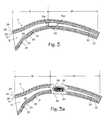
- FIGS. 3 and 3 aillustrate the prior art method of occluding the fallopian tubes using an occluding plug.
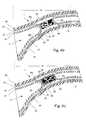
- FIGS. 4 and 4 aare cross sections of the utero-tubal junction of the female reproductive system with an organoid plug in place.
- FIGS. 4 b and 4 cillustrate the boundary response of wounded tissue with organoid plugs in place.
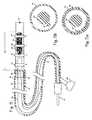
- FIG. 5is a drawing of the device used to deliver RF power and an occluding plug to the utero-tubal junction.
- FIGS. 5 a and 5 bshow the cross sections of the device illustrated in FIG. 5 .
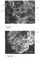
- FIGS. 6 and 6 aare microscopic views of the plug material used in the sterilization procedure.
- FIGS. 7 and 8are microscopic views of plug material used in the sterilization procedure.
- FIGS. 9 and 9 aillustrate the plug composition after placement and partial healing.
- FIG. 10illustrates the plug composition after placement and partial healing.
- FIG. 1shows some of the major elements of the female reproductive system.
- the uterus 2is an organ of the female pelvis that has the shape of a pear. It consists of a thick muscular coat, the myometrium 3 , a cavity having an inner mucosal lining of variable thickness called the endometrium 4 , and a cavity referred to as the uterine cavity 5 .
- the cervix 6defines the cervical canal 7 which is an inferior opening to the vagina 8 .
- the fallopian tube (or ampulla) 9is a hollow organ that connects the uterus to the ovary 10 .
- the ovary 15is the organ that produces one or more eggs during every cycle of a woman's reproductive life.
- the utero-tubal junction 11In the human female reproductive system, there is one uterus, two fallopian tubes and two ovaries (under normal conditions).
- the site where the fallopian tube and uterus connectis called the utero-tubal junction 11 . It is a section of tubular shape of about 10 mm in length. Its inner diameter in the resting position is less than 1 mm, but when gas or liquid is pushed through the uterus and tubes, the diameter of the utero-tubal junction may stretch up to about 2 mm.
- the utero-tubal junctionprovides a transition between the uterus and the fallopian tube, and the area of transition from the chamber of the uterus to the lumen of the utero-tubal junction is referred to as the ostium or cornu (marked with item number 12 ).
- the area of transition between the ostium and the isthmus 13 of the fallopian tubeis referred to as the interstitial portion (marked as item 14 ).
- the ostium, utero-tubal junction, interstitial portion, isthmus and fallopian tubeare part of a pathway leading from the ovaries to the uterus, and this pathway is sometimes referred to as the uterine tube.
- ovarian pathwayto denote the entire passageway through which the ova pass when transiting from the ovaries to the uterine cavity.
- FIG. 2shows the utero-tubal junction 11 , including the ostium 12 , the isthmus 13 , and the interstitial portion 14 .
- the cross sectionshows the layers of tissue that make up the utero-tubal junction.
- the lumen 20passes through the fallopian tube, and this lumen is lined with a layer of mucosal tissue consisting of epithelium 21 and lamina basement 23 . Within the fallopian tube, this layer of mucosal tissue is referred to as the endosalpinx, indicated as item 22 .
- the layer of tissue under the epithelial layeris the lamina basement, indicated as item 23 .
- the lamina limbaliumis surrounded by a layer of circular muscle 24 which is surrounded by layer of longitudinal muscle 25 .
- the longitudinal muscle layermay be surrounded with a second layer of circular muscle.
- the first circular muscle layer 24typically comprises about 10-14 layers of muscle cells.
- One aspect of the new treatment methodis the extent to which each of these layers is damaged prior to insertion of an occluding plug.
- FIG. 3illustrates an implanted plug 30 placed according to several old methods within the isthmus 13 of the fallopian tube.
- Plugshave also been proposed for implantation deep within the fallopian tubes, and in the ostium 12 .
- Sinnreich, Fallopian Tube Obturating Device, U.S. Pat. No. 3,918,431shows an ostial plug for temporary female sterilization.
- the epithelial layer 21is left intact, and is continuous over the lumen of the ostium/isthmus/fallopian tube in the area occluded by the plug.
- the epithelial layer 21 and/or endosalpinx 22will grow over the distal and proximal faces 31 d and 31 p (the longitudinal faces) of the plug. In time, the epithelial layer will recanalize the tube and form scar tissue over the plug, resulting in fistula formation around the plug in a number of treated patients.
- Zeluff, U.S. Pat. No. 4,606,336suggests use of a foam ring over (not in the lumen of) the ostium, which depends on fibroblast ingrowth into the ring to seal it to the ostium.
- this deviceis likely to be subject to the uterine foreign body response, leading to abnormal uterine bleeding, increased myometrial and tubal contractions and premature expulsion.
- FIG. 3 aillustrates the damage in each layer of the fallopian tube which occurs when using methods of the prior art which suggest ablation of the fallopian tubes followed by placement of a plug (the prior art methods do not suggest ablation at the utero-tubal junction).
- the poweris applied in amounts sufficient to damage the entire thickness of the fallopian tube, including the circular muscle layer 24 and longitudinal muscle layer 25 .
- Thisleads to a “standard foreign body response,” which is a term understood among scientists to include inflammation, encapsulation and eventual scar formation.
- the scar tissue 32will form in the wounded tissue (resulting in a fundamental change in the tubal architecture), and may also form within the plug if ingrowth is possible.
- an avascular fibrotic capsule 33may form around the plug to protect the host from the plug.
- the plugis eventually surrounded by scar tissue and a fibrotic capsule as indicated in FIG. 3 a .
- the biological process of the foreign body responsewill then operate to expel the plug.
- the bodymay also tend to develop epithelium/endosalpinx cells in place of the scar tissue, thereby creating a fistula around the plug, which could result in sperm passage and ova fertilization.
- the fertilized eggmay not be able to locomote through the fistula into the uterus, which would then trap the egg in the tube resulting in an ectopic pregnancy.
- FIG. 4illustrates the desired degree of damage in each layer of the utero-tubal junction, and the desired interaction between the tissue and the foam plug which is inserted to generate an occlusion of the fallopian tube.
- the foam plug 34is inserted into the target site for occlusion, which in this illustration is the utero-tubal junction.
- the plugis put in place after the target site has been treated with the application of thermal energy.
- the thermal energyis delivered at levels well below the level required to cause a severe burn (and the concomitant severe inflammatory response), but sufficient to cause thermal necrosis of the epithelial layer 21 and the lamina limba 23 .
- the area of thermal death(necrosis) is indicated as item 35 , and extends for a length of approximately 4 to 10 millimeters along the pathway. Damage to the circular muscle layer 24 is acceptable, but damage to the longitudinal muscle layer 25 is undesirable. This leads to minimal collapse of the utero-tubal junction about the plug.
- wound healing responseis a term understood in the art to include biological activities including: (1) arrival of leukocytes, neutrophils, monocytes, and their transformation into macrophages and aggregation into giant cells, and arrival of fibroblast cells, (collectively referred to as inflammatory cells), and (2) the creation of an extracellular matrix and deposition of proteins, and (3) the formation of granulation and connective tissue at the wound site.
- the wound healing responsemay continue to completion in the surrounding intact pathway, and will further entail reorganization of the granulation tissue into specialized and functional tissue corresponding to the original injured tissue (matching the architecture of the original tissue), and the formation of scar tissue (different from the tissue's original architecture).
- the tissue response immediately surrounding the plugdepends on the composition, pore size and architecture of the plug. For smooth plugs, the response will occur as discussed above in relation to FIGS. 3 and 3 a .
- the short term and long-term condition of the tissue immediately surrounding the plug and/or in-growing within the plugdepends on the pore size and architecture of the plug.
- the bodywill heal by forming a vascularized tissue within the pores of the foam.
- Inflammatory cellswill enter the foam pores, attract other cells, form extracellular matrix and connective tissue, and form into a collection of tissue referred to as granulation tissue within the pores of the foam.
- Subsequent healingincludes in-growth of vascular structures such as arterioles, capillaries and lymphatic vessels into the connective tissue residing within the pores of the foam. Because of the unique architecture and pore size of the foam, the granulation tissue will remain as granulation tissue indefinitely.
- the large pore plugin its final form within the body, will comprise numerous filaments of the foam superstructure which form a network of communicating pores, with granulation tissue occupying the pores.
- the plugwill also comprise numerous blood vessels formed within the granulation tissue, so that the tissue interspersed with the original plug material may be described as vascularized organic tissue.
- the vascularized tissueis vascularized to the same extent as is typical of other natural organs within the body.
- vascularized granulation tissuewill not form in the plug interstices.
- Subsequent healingincludes formation of a highly vascularized foreign body capsule and intrusion of some macrophages into the plug pores, without intrusion of other cells or tissue associated with the later stages of healing (such as extracellular matrix, granulation tissue and blood vessels). Instead, the body will form a vascularized capsule with blood vessels closely approaching the plug, lying adjacent and within about 10 um of the foam. This may be referred to as an altered foreign body response.
- FIG. 4 aillustrates the condition of the plug and ovarian pathway after the wound healing process has proceeded to the extent permitted by the continued presence of the plug.
- the several layers of the target site of the pathwayhave healed to form healing granulation tissue around the plug and throughout the wounded pathway. Placement of the plug directly against the wounded inner surface of the pathway has encouraged this tissue to surround the plug, and prevented epithelium from forming around the longitudinal surfaces of the plug.
- Epithelium 26has grown to cover the distal and proximal faces of the plug to form distal and proximal layers of tissue over the plug. The unwounded longitudinal muscle layer and remaining circular muscle layer remain in the pre-wound condition.
- FIG. 4 billustrates the condition of the large pore plug and ovarian pathway after the wound healing process has proceeded to the extent permitted by the continued presence of the plug.
- the several layers of the target site of the pathwayhave healed to form healing granulation tissue around the plug and throughout the wounded pathway. Placement of the plug directly against the wounded inner surface of the pathway after wounding has encouraged this tissue to surround the plug, and encouraged healing tissue penetration into the plug (and thus inhibited epithelium from forming around the longitudinal surfaces of the plug).
- Numerous blood vessels 36have entered or formed within the large pores.
- FIG. 4 cillustrates the condition of the small pore plug and ovarian pathway after the wound healing process has proceeded to the extent permitted by the continued presence of the plug.
- the several layers of the target site of the pathwayhave healed to form healing granulation tissue around the plug and throughout the wounded pathway. Placement of the plug directly against the wounded inner surface of the pathway after wounding has encouraged this tissue to surround the plug, and prevented epithelium from forming around the longitudinal surfaces of the plug.
- Scattered macrophages 37have entered the small pores, and a vascularized altered foreign body capsule 38 has formed around the plug.
- the vascularized foreign body capsuleincludes numerous blood vessels, and further progress of the foreign body response is inhibited.
- Epitheliumhas grown to cover the distal and proximal faces of the plug to form distal and proximal layers of tissue over the plug.
- the plugmay be infiltrated with vascularized granulation tissue (for plugs with large pore sizes in the range of 40-200 microns) or infiltrated with scattered macrophages and surrounded with a vascularized capsule of connective tissue (for plugs with small pore sizes in the range of 1-20 microns).
- vascularized granulation tissuefor plugs with large pore sizes in the range of 40-200 microns
- a vascularized capsule of connective tissuefor plugs with small pore sizes in the range of 1-20 microns.
- the plugis preferably made of a material with a pore size, chemistry and architecture that actually facilitates cellular ingrowth into the material (large pore plugs) or that allow macrophage infiltration but inhibit cellular ingrowth (small pore plugs).
- large pore plugsthe nature of the desired ingrowth is vastly different from the standard foreign body reaction. The primary difference is a type of ingrowth that consists of a variety of blood vessels, connective matrix and cells, macrophages, and other cells.
- the small pore plugsthe nature of the foreign body capsule is altered to include numerous blood vessels. These structures can be described as “organoid,” as they exist as an integral part of the organ.
- the plugmay be made of ePTFE (also referred to as expanded Teflon or expanded polytetraflouroethylene), porous silicone, acrylic copolymer, cellulose acetate, polyethylene and high density polyethylene (HDPE), PE, polyester, and sintered, micro-knurled, or molded titanium and platinum. Textured polyamides or polyimides, hydroxyapitite, and hydrogels are also potential suitable materials. Preferably, these materials are formed into a plug (a sphere, cylinder or other occluding mass) of foamed material. The preferable pore sizes of the foam fall into the two distinct ranges mentioned above, namely 1-20 micron pore size and 40-200 micron pore size (40-120 microns is even better).
- ePTFEalso referred to as expanded Teflon or expanded polytetraflouroethylene
- porous siliconeacrylic copolymer
- cellulose acetatepolyethylene and high density polyethylene (HDPE), PE, polyester, and sintered,
- the foamis preferably formed as a reticulated foam, meaning that the pores communicate with other pores, rather than existing as discrete and isolated voids within the material.
- the plugmay have a solid core surrounded by foam or a porous material having a reticulated network of pores.
- Silicone foamis readily formed into foam plugs with the procedure set forth in Seare, Method of Making A Porous Device , U.S. Pat. No. 5,605,693 (Feb. 25, 1997).
- Uncured siliconeMED 4860 grade supplied by Nusil Technology Corp is suitable
- the siliconeis cured and the particles are dissolved in a suitable solvent (water, where sugar or salt is used) to form the reticulated foam plug.
- the foam plughas a durometer value between 20-100 Shore A, preferably about 60 Shore A.
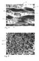
- FIGS. 6 and 6 aillustrate the two examples of the large pore foam plug.
- the foamis a matrix of interlocking angular blocks of silicone 45 (only a few are called out with the item number) which are formed together to create a network of communicating pores 46 with sizes corresponding to the size of the granules that were used to make the negative.
- the porescommunicate with surrounding pores to form a reticulated or networked foam.
- the pore size of the large foam pore illustrated in FIGS. 6 and 6 aare in the range of 40-200 microns (mu), the pore size of the foam in FIG. 6 a being smaller than the pore size of FIG. 6 .
- the structure of the small pore foamappears essentially the same as FIG. 6, except that the pore sizes is in the range of 1-20 microns.
- the plugmay be fabricated from expanded polytetraflouroethylene, commonly referred to as ePTFE, with the processes used for forming ePTFE generally. Starting with a PTFE rod, the rod is stretched to expand the PTFE to form the system of nodes and fibrils characteristic of ePTFE. Pore size (commonly referring to the distance between the nodes) and the number and size of fibrils connecting the nodes is controlled by stretching the PTFE rods at controlled rates and temperatures. (The plugs may also be fabricated from sheets of PTFE which are stretched to the degree necessary to create the desired porosity, then cut to shape.
- the plugsmay also be formed of very thin sheets of ePTFE which are used to coat or wrap a solid rod of PTFE.)
- the processresults in a material illustrated in FIG. 7 having microstructure characterized by elongate nodes 47 interconnected by fibrils 48 running between the nodes and extending generally perpendicular to the long dimension of the nodes.
- the pore size, as measured between the nodes,is in the range of 40 to 200 microns for large pore foam and 1 to 10 microns for small pore foam.
- the plugmay also be formed of acrylic copolymer (such as tetrafluoroethylene and hexafluoropropylene), as illustrated in FIG. 8 .
- the acrylic copolymeris formed as a mass of interlocking fibers 49 , which on the outer surface of the foam become outwardly extending rods 50 .
- the pore size, as measured by the distance between the rodsis preferably in the range of 1 to 10 microns.
- FIG. 5illustrates an embodiment in which the wounding energy source is RF energy.
- the catheterincludes a catheter body 51 with a wounding segment 52 comprising a short tubular extension slidably mounted within the distal tip 53 of the catheter.
- the distal tip of the catheter bodyextends over the proximal end of the tubular extension for a short length of 2-25 mm, which is sufficient to firmly hold the tubular extension during use.
- Four electrodes 54 , 55 , 56 and 57are aligned along the outer surface of the wounding segment.
- One or more temperature sensors 58are mounted on the wounding segment (a single temperature sensor may be mounted in the center of wounding segment, between the ground electrodes).
- the distal tip and wounding segmentare about 55 mil in outer diameter.
- the wounding segment in the RF embodimentis about 6 to 8 mm long, and the electrodes are ring electrodes which are about 0.037 to 0.050 inches wide (measured along of the longitudinal axis of the catheter) and wrap around the catheter.
- One or more foam plugs 34are stored within the catheter body, and are shown housed within the wounding segment.
- a long and shallow lesionmay be produced in the ovarian pathway when the electrodes are energized appropriately.
- the converse pattern of ground electrodes located on the distal and proximal ends of the wounding segment with energized electrodes located between the ground electrodesmay also be used to create the desired long and shallow lesion.
- the plugsmay be compressed to fit into the lumen 59 in the wounding segment of the catheter.
- a holding rod 60is disposed within the catheter body 51 , fixed longitudinally within the catheter body at any point distal to the wounding segment (it may be secured by gluing or heat sealing a proximal segment of the holding rod to the inner wall of the catheter body) which permits adequate pullback of the wounding segment to release the plug.
- a pullwire 61is secured to the proximal end of the wounding segment by attachment of the boss 62 on the distal end of the pullwire. The pullwire extends distally from the wounding segment to the proximal end of the catheter body.
- FIG. 5 ashows the cross section of the device along section 5 a , more clearly illustrating the relative positions of the pullwire boss 62 fixed to the inner wall of the wounding segment 52 , which itself is slidably disposed within the distal tip 53 of the catheter body 51 , and also slidably disposed around the holding rod 60 .
- FIG. 5 bshows the cross section of the device along cross section 5 b , more clearly illustrating the position of the holding rod 60 within the catheter body 51 .
- the pullwire 61can be manipulated by hand from the proximal end of the catheter to pull the wounding segment proximally within the catheter body.
- the holding rod 60maintains the plug (or plugs) in position within the ovarian pathway while the wounding segment is pulled proximally, thereby ejecting the plugs from the distal tip of the catheter without moving them relative to the wounded segment of the ovarian pathway after initial positioning (and also without moving the catheter body relative to the patient).
- Electrical wires which supply RF power to the electrodesmay run the through the lumen of the catheter body alongside the pullwire or they may be housed within the catheter body, and an electrical connector 63 is supplied on the proximal end of the catheter to connect the wires in the catheter to the RF power supply.
- the electrical wiresmay also be incorporated into the pullwire, with the electrical connections to the RF power supply being disposed on the proximal end of the pullwire.
- wounding mechanismsincluding resistive heating elements, direct laser irradiation, laser heated elements, microwave, ultrasound, piezo-electric abrasion, hypothermia, cryothermia, chemical ablation, and mechanical and physical abrasion.
- the catheterIn use, the catheter is inserted into the uterus transcervally, and the distal tip of the catheter is navigated into the fallopian tubes, until the wounding segment is stationed at the desired point along the ovarian pathway (the utero-tubal junction is our preferred location for the wound and the plug placement). Surgeons may view the placement with an endoscope or hysteroscope, and/or placement within the pathway can be confirmed with fluoroscopy. (Of course, placement of the catheter may be accomplished blindly, using tactile feedback only.) Once the wounding element is in place, the appropriate wound may be created by application of power limited so as destroy the epithelial layer/endosalpinx in the area of plug placement, yet avoid unwanted physiological reactions.
- the goalis to completely necrose the epithelium/endosalpinx, and to accomplish this goal, the surgeon applies sufficient wounding power to necrose the epithelium/endosalpinx, and the lamina intestinal, while limiting the wounding power to prevent damage to the longitudinal muscle layer. Damage to the circular muscle layer should be insubstantial, but may be tolerated.
- the wounding segmentis withdrawn by pulling the pullwire proximally while holding the catheter in place. This ejects the plug without need for relative motion between the plug and the wound after the operator has positioned the catheter for use.
- RF energywhen using RF energy as the wounding mechanism, we have determined that power of 0.1 to 5 watts for about 5 to 60 seconds causes thermal necrosis of the epithelial layer, without damaging the longitudinal muscle layer and without inducing an acute inflammatory response.
- temperature in the tissueis monitored with temperature sensors mounted on the delivery catheter wounding segment, and power is applied to maintain tissue temperature in the range of 40-80° C. for a period of 5 to 60 seconds.
- maintaining temperature of about 70° C. for 7 secondsworks well.
- maintaining temperature in the range of 52-58° C. for 40-60 secondsworks well.
- the heatingmay also be accomplished in two stages, heating briefly to 70-80° C. (5 to 10 seconds) followed by heating to 40-60° C. for an additional 30 to 60 seconds.
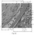
- FIGS. 9 and 9 aare photographs of an actual implant with the large pore foam.
- FIGS. 9shows the cross section of a bending segment of the ovarian pathway, which includes a view of the large pore plug in relation to the surrounding wounded ovarian pathway tissue, several weeks after implantation as well as an uninjured portion of the ovarian pathway.
- the silicone foam basis of the plug in this illustrationis the whitish gray irregular mass indicated as item 45 .
- the ingrown tissue 64 , surrounding wounded ovarian pathway tissue 65 and unwounded ovarian tissue 66have been dyed to assist in identifying the structures present.
- the ovarian pathway tissuevisible in FIG.
- FIG. 9includes the injured and healing lamina intestinal 67 , the injured and healing muscle layers 68 , and the uninjured longitudinal muscle 69 (the circular and longitudinal layers cannot be readily distinguished in the photograph, and are located in the area indicated by item number indicated 70 ).
- the epithelial/endosalpinx layeris not present, having been destroyed by the wounding process (although the epithelial layer 71 is visible in the unwounded tissue 66 .
- Other structures which are visibleinclude serosa 72 , the plicae (folds) 73 of the ovarian pathway in the unwounded tissue 66 .
- the details of the wound healing tissue 64 within the plugare visible in the higher magnification view of FIG. 9 a , which is an enlargement of the area 74 of FIG.
- FIG. 10is a photograph of a plug comprising a bilaminar membrane 77 comprising the small pore ePTFE, a smooth membrane ePTFE and the surrounding ovarian pathway tissue.
- the plugis actually two sided, having a small pore side 78 with 5 micron pore ePTFE on the right, and an essentially smooth side 79 with 0.45 micron pore ePTFE on the left.
- FIG. 10shows the cross section of this two sided plug in relation to the surrounding ovarian pathway tissue, several weeks after implantation.
- FIG. 10is a photograph of a plug comprising a bilaminar membrane 77 comprising the small pore ePTFE, a smooth membrane ePTFE and the surrounding ovarian pathway tissue.
- the plugis actually two sided, having a small pore side 78 with 5 micron pore ePTFE on the right, and an essentially smooth side 79 with 0.45 micron pore ePTFE on the left.
- FIG. 10shows
- the healing lamina limbal 67 the injured and healing circular muscle layer 68 , and the uninjured longitudinal muscle 69are not visible around the plug in this close up view.
- a vascularized foreign body capsule 38On the small pore side of the plug, a vascularized foreign body capsule 38 has developed.
- the blood vessels 81 formed within the vascularized altered foreign body capsule 38are seen closely approaching the plug (individual red blood cells 82 can be seen inside the blood vessels).
- Other structures which are visibleinclude extracellular matrix 76 , scattered macrophages 37 , mononuclear leukocytes 75 and giant cells 83 .
- the avascular fibrotic capsule 33 characteristic of the foreign body responseis visible.
- the avascular fibrotic capsuleis composed entirely of extracellular matrix 76 and scattered fibroblast cells 84 throughout the extracellular matrix. No blood vessels have formed in the avascular fibrotic capsule, a clear sign that the smooth side of the plug has been isolated by the foreign body response. (The white spaces 85 are merely separations between various structures created when the tissue surrounding the plug was splayed for histology.)
Landscapes
- Health & Medical Sciences (AREA)
- Life Sciences & Earth Sciences (AREA)
- Surgery (AREA)
- Engineering & Computer Science (AREA)
- General Health & Medical Sciences (AREA)
- Biomedical Technology (AREA)
- Heart & Thoracic Surgery (AREA)
- Animal Behavior & Ethology (AREA)
- Public Health (AREA)
- Veterinary Medicine (AREA)
- Nuclear Medicine, Radiotherapy & Molecular Imaging (AREA)
- Vascular Medicine (AREA)
- Medical Informatics (AREA)
- Molecular Biology (AREA)
- Reproductive Health (AREA)
- Physics & Mathematics (AREA)
- Plasma & Fusion (AREA)
- Otolaryngology (AREA)
- Surgical Instruments (AREA)
- Materials For Medical Uses (AREA)
- Gyroscopes (AREA)
- Steroid Compounds (AREA)
- Prostheses (AREA)
- Radiation-Therapy Devices (AREA)
- Sampling And Sample Adjustment (AREA)
- Centrifugal Separators (AREA)
Abstract
Description
Claims (32)
Priority Applications (4)
| Application Number | Priority Date | Filing Date | Title |
|---|---|---|---|
| US09/810,761US6712810B2 (en) | 1999-02-01 | 2001-03-16 | Method and apparatus for tubal occlusion |
| US10/812,476US7842035B2 (en) | 1999-02-01 | 2004-03-29 | Method and apparatus for tubal occlusion |
| US11/562,882US8702727B1 (en) | 1999-02-01 | 2006-11-22 | Delivery catheter with implant ejection mechanism |
| US12/912,087US8226645B2 (en) | 1999-02-01 | 2010-10-26 | Apparatus for tubal occlusion |
Applications Claiming Priority (2)
| Application Number | Priority Date | Filing Date | Title |
|---|---|---|---|
| US09/241,790US6309384B1 (en) | 1999-02-01 | 1999-02-01 | Method and apparatus for tubal occlusion |
| US09/810,761US6712810B2 (en) | 1999-02-01 | 2001-03-16 | Method and apparatus for tubal occlusion |
Related Parent Applications (1)
| Application Number | Title | Priority Date | Filing Date |
|---|---|---|---|
| US09/241,790ContinuationUS6309384B1 (en) | 1999-02-01 | 1999-02-01 | Method and apparatus for tubal occlusion |
Related Child Applications (1)
| Application Number | Title | Priority Date | Filing Date |
|---|---|---|---|
| US10/812,476ContinuationUS7842035B2 (en) | 1999-02-01 | 2004-03-29 | Method and apparatus for tubal occlusion |
Publications (2)
| Publication Number | Publication Date |
|---|---|
| US20010016738A1 US20010016738A1 (en) | 2001-08-23 |
| US6712810B2true US6712810B2 (en) | 2004-03-30 |
Family
ID=22912188
Family Applications (4)
| Application Number | Title | Priority Date | Filing Date |
|---|---|---|---|
| US09/241,790Expired - LifetimeUS6309384B1 (en) | 1999-02-01 | 1999-02-01 | Method and apparatus for tubal occlusion |
| US09/810,761Expired - LifetimeUS6712810B2 (en) | 1999-02-01 | 2001-03-16 | Method and apparatus for tubal occlusion |
| US10/812,476Expired - Fee RelatedUS7842035B2 (en) | 1999-02-01 | 2004-03-29 | Method and apparatus for tubal occlusion |
| US12/912,087Expired - Fee RelatedUS8226645B2 (en) | 1999-02-01 | 2010-10-26 | Apparatus for tubal occlusion |
Family Applications Before (1)
| Application Number | Title | Priority Date | Filing Date |
|---|---|---|---|
| US09/241,790Expired - LifetimeUS6309384B1 (en) | 1999-02-01 | 1999-02-01 | Method and apparatus for tubal occlusion |
Family Applications After (2)
| Application Number | Title | Priority Date | Filing Date |
|---|---|---|---|
| US10/812,476Expired - Fee RelatedUS7842035B2 (en) | 1999-02-01 | 2004-03-29 | Method and apparatus for tubal occlusion |
| US12/912,087Expired - Fee RelatedUS8226645B2 (en) | 1999-02-01 | 2010-10-26 | Apparatus for tubal occlusion |
Country Status (11)
| Country | Link |
|---|---|
| US (4) | US6309384B1 (en) |
| EP (2) | EP2191797B1 (en) |
| JP (1) | JP2003520618A (en) |
| CN (1) | CN100360098C (en) |
| AT (2) | ATE527969T1 (en) |
| AU (2) | AU767864B2 (en) |
| CA (1) | CA2360586A1 (en) |
| DE (1) | DE60044237D1 (en) |
| ES (2) | ES2372017T3 (en) |
| HK (1) | HK1039270B (en) |
| WO (1) | WO2000044323A1 (en) |
Cited By (48)
| Publication number | Priority date | Publication date | Assignee | Title |
|---|---|---|---|---|
| US20040127918A1 (en)* | 1995-06-07 | 2004-07-01 | Conceptus, Inc. | Contraceptive transcervical fallopian tube occlusion devices and methods |
| US20040255958A1 (en)* | 1999-02-01 | 2004-12-23 | Adiana, Inc. | Method and apparatus for tubal occlusion |
| US20050234543A1 (en)* | 2004-03-30 | 2005-10-20 | Nmt Medical, Inc. | Plug for use in left atrial appendage |
| US20060247614A1 (en)* | 2005-04-28 | 2006-11-02 | Sampson Russel M | Hemostasis device |
| US20070050001A1 (en)* | 2005-08-26 | 2007-03-01 | Solarant Medical, Inc. | Adjustable open loop control devices and methods |
| US20070044808A1 (en)* | 1995-06-07 | 2007-03-01 | Conceptus, Inc., A California Corporation | Contraceptive transcervical fallopian tube occlusion devices and their delivery |
| US20080039828A1 (en)* | 2006-08-10 | 2008-02-14 | Jimenez Jose W | Laser Tissue Vaporization |
| US20080071269A1 (en)* | 2006-09-18 | 2008-03-20 | Cytyc Corporation | Curved Endoscopic Medical Device |
| US20080071257A1 (en)* | 2006-09-18 | 2008-03-20 | Cytyc Corporation | Power Ramping During RF Ablation |
| WO2008067266A1 (en) | 2006-11-28 | 2008-06-05 | Cytyc Corporation | Side-arm port introducer |
| WO2008077123A1 (en)* | 2006-12-19 | 2008-06-26 | The Regents Of The University Of Colorado | Shape memory polymer-based transcervical device for permanent or temporary sterilization |
| US20090036840A1 (en)* | 2006-11-22 | 2009-02-05 | Cytyc Corporation | Atraumatic ball tip and side wall opening |
| US20090125023A1 (en)* | 2007-11-13 | 2009-05-14 | Cytyc Corporation | Electrosurgical Instrument |
| US20090248141A1 (en)* | 2006-03-30 | 2009-10-01 | The Regents Of The University Of Colorado | Shape Memory Polymer Medical Devices |
| US20100036372A1 (en)* | 1996-04-12 | 2010-02-11 | Csaba Truckai | Moisture transport system for contact electrocoagulation |
| US20100086492A1 (en)* | 2008-10-03 | 2010-04-08 | Kathy Lee-Sepsick | Methods and devices for sonographic imaging |
| US7731712B2 (en) | 2004-12-20 | 2010-06-08 | Cytyc Corporation | Method and system for transcervical tubal occlusion |
| US20100152839A1 (en)* | 2008-10-29 | 2010-06-17 | The Regents Of The University Of Colorado, A Body Corporate | Shape Memory Polymer Prosthetic Medical Device |
| US7780639B2 (en) | 2003-11-12 | 2010-08-24 | Van Lue Stephen J | Magnetic devices and apparatus for medical/surgical procedures and methods for using same |
| US7846160B2 (en) | 2006-12-21 | 2010-12-07 | Cytyc Corporation | Method and apparatus for sterilization |
| US7905880B2 (en) | 1997-06-05 | 2011-03-15 | Cytyc Corporation | Method and apparatus for tubal occlusion |
| WO2011089436A2 (en) | 2010-01-22 | 2011-07-28 | Cytyc Corporation | Sterilization device and method |
| US8048101B2 (en) | 2004-02-25 | 2011-11-01 | Femasys Inc. | Methods and devices for conduit occlusion |
| US8048086B2 (en) | 2004-02-25 | 2011-11-01 | Femasys Inc. | Methods and devices for conduit occlusion |
| US8052669B2 (en) | 2004-02-25 | 2011-11-08 | Femasys Inc. | Methods and devices for delivery of compositions to conduits |
| US20120111337A1 (en)* | 2007-08-28 | 2012-05-10 | Betsy Swann | Methods and devices for occluding an ovarian pathway |
| US8479742B2 (en) | 2011-02-28 | 2013-07-09 | Hologic, Inc. | Constant rate delivery device |
| US8550086B2 (en) | 2010-05-04 | 2013-10-08 | Hologic, Inc. | Radiopaque implant |
| US8551082B2 (en) | 1998-05-08 | 2013-10-08 | Cytyc Surgical Products | Radio-frequency generator for powering an ablation device |
| US8702727B1 (en) | 1999-02-01 | 2014-04-22 | Hologic, Inc. | Delivery catheter with implant ejection mechanism |
| US8968284B2 (en) | 2000-10-02 | 2015-03-03 | Verathon Inc. | Apparatus and methods for treating female urinary incontinence |
| US9023031B2 (en) | 1997-08-13 | 2015-05-05 | Verathon Inc. | Noninvasive devices, methods, and systems for modifying tissues |
| US9238127B2 (en) | 2004-02-25 | 2016-01-19 | Femasys Inc. | Methods and devices for delivering to conduit |
| US9427493B2 (en) | 2011-03-07 | 2016-08-30 | The Regents Of The University Of Colorado | Shape memory polymer intraocular lenses |
| US9492312B2 (en) | 2010-10-18 | 2016-11-15 | Bioceptive, Inc. | Methods and apparatus for inserting a device or pharmaceutical into a body cavity |
| US9554826B2 (en) | 2008-10-03 | 2017-01-31 | Femasys, Inc. | Contrast agent injection system for sonographic imaging |
| US9731045B2 (en) | 2005-04-01 | 2017-08-15 | The Regents Of The University Of Colorado | Shape memory polymer |
| US9808252B2 (en) | 2009-04-02 | 2017-11-07 | Endoshape, Inc. | Vascular occlusion devices |
| US10201351B2 (en) | 2011-09-30 | 2019-02-12 | Endoshape, Inc. | Continuous embolic coil and methods and devices for delivery of the same |
| US10603043B2 (en) | 2012-01-17 | 2020-03-31 | Endoshape, Inc. | Occlusion device for a vascular or biological lumen |
| US10617425B2 (en) | 2014-03-10 | 2020-04-14 | Conformal Medical, Inc. | Devices and methods for excluding the left atrial appendage |
| US10722240B1 (en) | 2019-02-08 | 2020-07-28 | Conformal Medical, Inc. | Devices and methods for excluding the left atrial appendage |
| US11026695B2 (en) | 2016-10-27 | 2021-06-08 | Conformal Medical, Inc. | Devices and methods for excluding the left atrial appendage |
| US11399842B2 (en) | 2013-03-13 | 2022-08-02 | Conformal Medical, Inc. | Devices and methods for excluding the left atrial appendage |
| US11426172B2 (en) | 2016-10-27 | 2022-08-30 | Conformal Medical, Inc. | Devices and methods for excluding the left atrial appendage |
| US11717303B2 (en) | 2013-03-13 | 2023-08-08 | Conformal Medical, Inc. | Devices and methods for excluding the left atrial appendage |
| US12144508B2 (en) | 2019-02-08 | 2024-11-19 | Conformal Medical, Inc. | Devices and methods for excluding the left atrial appendage |
| US12171463B2 (en) | 2008-10-03 | 2024-12-24 | Femasys Inc. | Contrast agent generation and injection system for sonographic imaging |
Families Citing this family (125)
| Publication number | Priority date | Publication date | Assignee | Title |
|---|---|---|---|---|
| US20050033132A1 (en) | 1997-03-04 | 2005-02-10 | Shults Mark C. | Analyte measuring device |
| US7192450B2 (en) | 2003-05-21 | 2007-03-20 | Dexcom, Inc. | Porous membranes for use with implantable devices |
| US6741877B1 (en) | 1997-03-04 | 2004-05-25 | Dexcom, Inc. | Device and method for determining analyte levels |
| US6001067A (en) | 1997-03-04 | 1999-12-14 | Shults; Mark C. | Device and method for determining analyte levels |
| US8688188B2 (en) | 1998-04-30 | 2014-04-01 | Abbott Diabetes Care Inc. | Analyte monitoring device and methods of use |
| US6175752B1 (en) | 1998-04-30 | 2001-01-16 | Therasense, Inc. | Analyte monitoring device and methods of use |
| US8346337B2 (en) | 1998-04-30 | 2013-01-01 | Abbott Diabetes Care Inc. | Analyte monitoring device and methods of use |
| US8465425B2 (en) | 1998-04-30 | 2013-06-18 | Abbott Diabetes Care Inc. | Analyte monitoring device and methods of use |
| US9066695B2 (en) | 1998-04-30 | 2015-06-30 | Abbott Diabetes Care Inc. | Analyte monitoring device and methods of use |
| US8974386B2 (en) | 1998-04-30 | 2015-03-10 | Abbott Diabetes Care Inc. | Analyte monitoring device and methods of use |
| US8480580B2 (en) | 1998-04-30 | 2013-07-09 | Abbott Diabetes Care Inc. | Analyte monitoring device and methods of use |
| US6949816B2 (en) | 2003-04-21 | 2005-09-27 | Motorola, Inc. | Semiconductor component having first surface area for electrically coupling to a semiconductor chip and second surface area for electrically coupling to a substrate, and method of manufacturing same |
| US6464628B1 (en) | 1999-08-12 | 2002-10-15 | Obtech Medical Ag | Mechanical anal incontinence |
| US6482145B1 (en) | 2000-02-14 | 2002-11-19 | Obtech Medical Ag | Hydraulic anal incontinence treatment |
| US6471635B1 (en) | 2000-02-10 | 2002-10-29 | Obtech Medical Ag | Anal incontinence disease treatment with controlled wireless energy supply |
| US6709667B1 (en) | 1999-08-23 | 2004-03-23 | Conceptus, Inc. | Deployment actuation system for intrafallopian contraception |
| CA2635435C (en) | 2000-02-10 | 2010-05-25 | Potencia Medical Ag | Controlled urinary incontinence treatment |
| ATE391468T1 (en) | 2000-02-10 | 2008-04-15 | Potencia Medical Ag | MECHANICAL DEVICE FOR IMPOTENCY TREATMENT |
| ATE416743T1 (en) | 2000-02-11 | 2008-12-15 | Potentica Ag | DEVICE WITH ENERGY CONVERSION MEANS FOR TREATING IMPOTENCY |
| WO2001047440A2 (en) | 2000-02-14 | 2001-07-05 | Potencia Medical Ag | Male impotence prosthesis apparatus with wireless energy supply |
| US7442165B2 (en) | 2000-02-14 | 2008-10-28 | Obtech Medical Ag | Penile prosthesis |
| AU2001257212B9 (en)* | 2000-04-25 | 2007-03-29 | Impres Medical, Inc. | Method and apparatus for creating intrauterine adhesions |
| US6560471B1 (en) | 2001-01-02 | 2003-05-06 | Therasense, Inc. | Analyte monitoring device and methods of use |
| US6550480B2 (en)* | 2001-01-31 | 2003-04-22 | Numed/Tech Llc | Lumen occluders made from thermodynamic materials |
| EP1397068A2 (en) | 2001-04-02 | 2004-03-17 | Therasense, Inc. | Blood glucose tracking apparatus and methods |
| US20030032874A1 (en) | 2001-07-27 | 2003-02-13 | Dexcom, Inc. | Sensor head for use with implantable devices |
| US6702857B2 (en) | 2001-07-27 | 2004-03-09 | Dexcom, Inc. | Membrane for use with implantable devices |
| US7418966B2 (en)* | 2001-10-22 | 2008-09-02 | O. R. Solutions, Inc. | Surgical drape and method of detecting fluid and leaks in thermal treatment system basins |
| US7613491B2 (en) | 2002-05-22 | 2009-11-03 | Dexcom, Inc. | Silicone based membranes for use in implantable glucose sensors |
| US8010174B2 (en) | 2003-08-22 | 2011-08-30 | Dexcom, Inc. | Systems and methods for replacing signal artifacts in a glucose sensor data stream |
| US9247901B2 (en) | 2003-08-22 | 2016-02-02 | Dexcom, Inc. | Systems and methods for replacing signal artifacts in a glucose sensor data stream |
| US8260393B2 (en) | 2003-07-25 | 2012-09-04 | Dexcom, Inc. | Systems and methods for replacing signal data artifacts in a glucose sensor data stream |
| US8364229B2 (en) | 2003-07-25 | 2013-01-29 | Dexcom, Inc. | Analyte sensors having a signal-to-noise ratio substantially unaffected by non-constant noise |
| US7226978B2 (en) | 2002-05-22 | 2007-06-05 | Dexcom, Inc. | Techniques to improve polyurethane membranes for implantable glucose sensors |
| US6780182B2 (en)* | 2002-05-23 | 2004-08-24 | Adiana, Inc. | Catheter placement detection system and operator interface |
| US7134999B2 (en) | 2003-04-04 | 2006-11-14 | Dexcom, Inc. | Optimized sensor geometry for an implantable glucose sensor |
| BRPI0410324A (en) | 2003-05-15 | 2006-05-23 | Biomerix Corp | implantable device, elastomeric matrix production lyophilization processes having a cross-linked structure, polymerization for cross-linked elastomeric matrix preparation and cross-linked composite elastomeric implant preparation, and method for treating an orthopedic disorder |
| US7875293B2 (en) | 2003-05-21 | 2011-01-25 | Dexcom, Inc. | Biointerface membranes incorporating bioactive agents |
| US9763609B2 (en) | 2003-07-25 | 2017-09-19 | Dexcom, Inc. | Analyte sensors having a signal-to-noise ratio substantially unaffected by non-constant noise |
| WO2007120442A2 (en) | 2003-07-25 | 2007-10-25 | Dexcom, Inc. | Dual electrode system for a continuous analyte sensor |
| US8423113B2 (en) | 2003-07-25 | 2013-04-16 | Dexcom, Inc. | Systems and methods for processing sensor data |
| US7774145B2 (en) | 2003-08-01 | 2010-08-10 | Dexcom, Inc. | Transcutaneous analyte sensor |
| US8275437B2 (en) | 2003-08-01 | 2012-09-25 | Dexcom, Inc. | Transcutaneous analyte sensor |
| US7591801B2 (en) | 2004-02-26 | 2009-09-22 | Dexcom, Inc. | Integrated delivery device for continuous glucose sensor |
| US8160669B2 (en) | 2003-08-01 | 2012-04-17 | Dexcom, Inc. | Transcutaneous analyte sensor |
| US9135402B2 (en) | 2007-12-17 | 2015-09-15 | Dexcom, Inc. | Systems and methods for processing sensor data |
| US7920906B2 (en) | 2005-03-10 | 2011-04-05 | Dexcom, Inc. | System and methods for processing analyte sensor data for sensor calibration |
| US20140121989A1 (en) | 2003-08-22 | 2014-05-01 | Dexcom, Inc. | Systems and methods for processing analyte sensor data |
| US8579892B2 (en) | 2003-10-07 | 2013-11-12 | Tsunami Medtech, Llc | Medical system and method of use |
| EP1682014A4 (en) | 2003-10-14 | 2010-11-17 | Pluromed Inc | Confinement of kidney-stone fragments during lithotripsy |
| US9247900B2 (en) | 2004-07-13 | 2016-02-02 | Dexcom, Inc. | Analyte sensor |
| ATE480761T1 (en) | 2003-12-05 | 2010-09-15 | Dexcom Inc | CALIBRATION METHODS FOR A CONTINUOUSLY WORKING ANALYTICAL SENSOR |
| US8423114B2 (en) | 2006-10-04 | 2013-04-16 | Dexcom, Inc. | Dual electrode system for a continuous analyte sensor |
| US11633133B2 (en) | 2003-12-05 | 2023-04-25 | Dexcom, Inc. | Dual electrode system for a continuous analyte sensor |
| US7763077B2 (en) | 2003-12-24 | 2010-07-27 | Biomerix Corporation | Repair of spinal annular defects and annulo-nucleoplasty regeneration |
| US20050149016A1 (en)* | 2003-12-29 | 2005-07-07 | Centum Research Llc | Laparoscopic device and method of female sterilization |
| US20050165480A1 (en)* | 2004-01-23 | 2005-07-28 | Maybelle Jordan | Endovascular treatment devices and methods |
| US7364592B2 (en)* | 2004-02-12 | 2008-04-29 | Dexcom, Inc. | Biointerface membrane with macro-and micro-architecture |
| US8808228B2 (en) | 2004-02-26 | 2014-08-19 | Dexcom, Inc. | Integrated medicament delivery device for use with continuous analyte sensor |
| WO2009048462A1 (en) | 2007-10-09 | 2009-04-16 | Dexcom, Inc. | Integrated insulin delivery system with continuous glucose sensor |
| US7783333B2 (en) | 2004-07-13 | 2010-08-24 | Dexcom, Inc. | Transcutaneous medical device with variable stiffness |
| US8452368B2 (en) | 2004-07-13 | 2013-05-28 | Dexcom, Inc. | Transcutaneous analyte sensor |
| US7654956B2 (en) | 2004-07-13 | 2010-02-02 | Dexcom, Inc. | Transcutaneous analyte sensor |
| US8565848B2 (en) | 2004-07-13 | 2013-10-22 | Dexcom, Inc. | Transcutaneous analyte sensor |
| US20060016700A1 (en) | 2004-07-13 | 2006-01-26 | Dexcom, Inc. | Transcutaneous analyte sensor |
| US20070045902A1 (en) | 2004-07-13 | 2007-03-01 | Brauker James H | Analyte sensor |
| US8886272B2 (en) | 2004-07-13 | 2014-11-11 | Dexcom, Inc. | Analyte sensor |
| US8662081B2 (en)* | 2005-02-15 | 2014-03-04 | Yale University | Intrauterine device |
| US7392768B2 (en) | 2005-04-29 | 2008-07-01 | Tendix Development, Llc | Radial impulse engine, pump, and compressor systems, and associated methods of operation |
| ES2529130T3 (en) | 2005-05-02 | 2015-02-17 | Genzyme Corporation | Non-lithotropic kidney stone therapy |
| US20070023534A1 (en)* | 2005-07-22 | 2007-02-01 | Mingsheng Liu | Water-source heat pump control system and method |
| US20080243068A1 (en)* | 2005-12-29 | 2008-10-02 | Kamal Ramzipoor | Methods and apparatus for treatment of venous insufficiency |
| US20070163601A1 (en)* | 2006-01-17 | 2007-07-19 | Neil Pollock | Apparatus and method for reversible male and female contraceptive implants |
| WO2007102842A2 (en) | 2006-03-09 | 2007-09-13 | Dexcom, Inc. | Systems and methods for processing analyte sensor data |
| US7975697B2 (en)* | 2006-05-11 | 2011-07-12 | Conceptus, Inc. | Methods and apparatus for occluding reproductive tracts to effect contraception |
| WO2007143225A2 (en) | 2006-06-07 | 2007-12-13 | Abbott Diabetes Care, Inc. | Analyte monitoring system and method |
| US8012166B2 (en)* | 2006-07-06 | 2011-09-06 | Centum Research Llc | Laparoscopic instrument tip and method of specimen collection |
| AU2007307639B2 (en)* | 2006-10-12 | 2013-03-21 | Aub Holdings Llc | Method and apparatus for occluding a lumen |
| US20080140002A1 (en)* | 2006-12-06 | 2008-06-12 | Kamal Ramzipoor | System for delivery of biologically active substances with actuating three dimensional surface |
| US20200037874A1 (en) | 2007-05-18 | 2020-02-06 | Dexcom, Inc. | Analyte sensors having a signal-to-noise ratio substantially unaffected by non-constant noise |
| WO2008154312A1 (en) | 2007-06-08 | 2008-12-18 | Dexcom, Inc. | Integrated medicament delivery device for use with continuous analyte sensor |
| EP2190373B1 (en) | 2007-08-23 | 2013-01-09 | Aegea Medical, Inc. | Uterine therapy device |
| US10195325B2 (en)* | 2007-10-11 | 2019-02-05 | Peter Forsell | Method for controlling flow of sperms in a uterine tube |
| US8795153B2 (en) | 2007-10-11 | 2014-08-05 | Peter Forsell | Method for treating female sexual dysfunction |
| ES2876250T3 (en) | 2007-10-11 | 2021-11-12 | Implantica Patent Ltd | Apparatus for controlling flow in a body organ |
| US8992409B2 (en) | 2007-10-11 | 2015-03-31 | Peter Forsell | Method for controlling flow in a bodily organ |
| US8696543B2 (en) | 2007-10-11 | 2014-04-15 | Kirk Promotion Ltd. | Method for controlling flow of intestinal contents in a patient's intestines |
| WO2009072039A2 (en)* | 2007-12-06 | 2009-06-11 | Koninklijke Philips Electronics N.V. | Apparatus, method and computer program for applying energy to an object |
| US8290559B2 (en) | 2007-12-17 | 2012-10-16 | Dexcom, Inc. | Systems and methods for processing sensor data |
| WO2009096851A1 (en) | 2008-01-28 | 2009-08-06 | Milux Holding Sa | A drainage device comprising a filter cleaning device |
| MX2010008003A (en) | 2008-01-29 | 2010-09-24 | Milux Holding Sa | Apparatus for treating obesity. |
| US8241324B2 (en)* | 2008-03-03 | 2012-08-14 | Eilaz Babaev | Ultrasonic vascular closure device |
| WO2010042011A1 (en) | 2008-10-10 | 2010-04-15 | Milux Holding Sa | Heart help device, system, and method |
| US8874215B2 (en) | 2008-10-10 | 2014-10-28 | Peter Forsell | System, an apparatus, and a method for treating a sexual dysfunctional female patient |
| WO2010042046A1 (en) | 2008-10-10 | 2010-04-15 | Milux Holding S.A. | Apparatus, system and operation method for the treatment of female sexual dysfunction |
| EP3851076A1 (en) | 2008-10-10 | 2021-07-21 | MedicalTree Patent Ltd. | An improved artificial valve |
| WO2010042018A1 (en) | 2008-10-10 | 2010-04-15 | Milux Holding S.A. | Heart help device, system and method |
| AU2009302955B2 (en) | 2008-10-10 | 2017-01-05 | Implantica Patent Ltd. | Fastening means for implantable medical control assembly |
| US10952836B2 (en) | 2009-07-17 | 2021-03-23 | Peter Forsell | Vaginal operation method for the treatment of urinary incontinence in women |
| US9949812B2 (en) | 2009-07-17 | 2018-04-24 | Peter Forsell | Vaginal operation method for the treatment of anal incontinence in women |
| US20110146692A1 (en)* | 2009-12-23 | 2011-06-23 | Hologic, Inc. | Implant Delivery Device |
| US8920447B2 (en)* | 2010-10-19 | 2014-12-30 | Apollo Endosurgery, Inc. | Articulated gastric implant clip |
| US8550087B2 (en)* | 2010-11-05 | 2013-10-08 | Hologic, Inc. | Implant delivery device with expanding tip |
| ES2912362T3 (en) | 2010-11-09 | 2022-05-25 | Aegea Medical Inc | Method of placement and apparatus for delivering steam to the uterus |
| US9655557B2 (en) | 2011-02-04 | 2017-05-23 | Minerva Surgical, Inc. | Methods and systems for evaluating the integrity of a uterine cavity |
| CA2851355C (en) | 2011-10-07 | 2020-02-18 | Aegea Medical Inc. | Integrity testing method and apparatus for delivering vapor to the uterus |
| CN102871788B (en)* | 2012-09-28 | 2015-01-21 | 王天奇 | Inflatable lumen plug |
| GB2507053A (en)* | 2012-10-16 | 2014-04-23 | Jonathan Featherstone | Nephroureterectomy apparatus |
| US10327781B2 (en)* | 2012-11-13 | 2019-06-25 | Covidien Lp | Occlusive devices |
| US9278187B2 (en)* | 2013-03-13 | 2016-03-08 | Biosense Webster (Israel) Ltd. | Method for making a low OHMIC pressure-contact electrical connection between split ring electrode and lead wire |
| US10179019B2 (en) | 2014-05-22 | 2019-01-15 | Aegea Medical Inc. | Integrity testing method and apparatus for delivering vapor to the uterus |
| JP6825789B2 (en) | 2014-11-19 | 2021-02-03 | エピックス セラピューティクス,インコーポレイテッド | Systems and methods for high resolution mapping of tissues |
| JP6725178B2 (en) | 2014-11-19 | 2020-07-15 | エピックス セラピューティクス,インコーポレイテッド | Ablation apparatus, systems and methods using high resolution electrode assemblies |
| WO2016081611A1 (en) | 2014-11-19 | 2016-05-26 | Advanced Cardiac Therapeutics, Inc. | High-resolution mapping of tissue with pacing |
| US10548664B2 (en) | 2015-03-16 | 2020-02-04 | Hermes Innovations, LLC | Systems and methods for permanent female contraception |
| US9636164B2 (en) | 2015-03-25 | 2017-05-02 | Advanced Cardiac Therapeutics, Inc. | Contact sensing systems and methods |
| EP3416551B1 (en) | 2016-02-19 | 2022-10-12 | Aegea Medical Inc. | Apparatus for determining the integrity of a bodily cavity |
| WO2017160808A1 (en) | 2016-03-15 | 2017-09-21 | Advanced Cardiac Therapeutics, Inc. | Improved devices, systems and methods for irrigated ablation |
| CN110809448B (en) | 2017-04-27 | 2022-11-25 | Epix疗法公司 | Determining properties of contact between catheter tip and tissue |
| EP4223243A1 (en) | 2017-06-20 | 2023-08-09 | Aegea Medical Inc. | Induction coil assembly for uterine ablation and method |
| US20190120785A1 (en) | 2017-10-24 | 2019-04-25 | Dexcom, Inc. | Pre-connected analyte sensors |
| US11331022B2 (en) | 2017-10-24 | 2022-05-17 | Dexcom, Inc. | Pre-connected analyte sensors |
| US11076982B2 (en)* | 2017-12-29 | 2021-08-03 | Gyrus Acmi, Inc. | Fallopian biocompatible plug with differently expandable portions |
| CN108742492A (en)* | 2018-06-29 | 2018-11-06 | 辛琰琰 | non-porous culdoscope |
| CN113101039B (en)* | 2021-04-26 | 2022-10-18 | 金浙滔 | A fallopian tube contraceptive device, implanter and extractor |
Citations (42)
| Publication number | Priority date | Publication date | Assignee | Title |
|---|---|---|---|---|
| US2102270A (en) | 1935-11-29 | 1937-12-14 | Mortimer N Hyams | Electrosurgical device |
| US3680542A (en) | 1970-05-11 | 1972-08-01 | Hugo S Cimber | Device for occlusion of an oviduct |
| US3805767A (en) | 1973-02-26 | 1974-04-23 | Erb Rene | Method and apparatus for non-surgical, reversible sterilization of females |
| US3840016A (en) | 1972-03-10 | 1974-10-08 | H Lindemann | Electrocoagulation-bougie for the intrauterine tube sterilization |
| US3858586A (en) | 1971-03-11 | 1975-01-07 | Martin Lessen | Surgical method and electrode therefor |
| US3858571A (en) | 1973-07-02 | 1975-01-07 | Arthur I Rudolph | Cornual plug |
| US3918431A (en) | 1974-01-11 | 1975-11-11 | Manfred Sinnreich | Fallopian tube obturating device |
| US3938527A (en) | 1973-07-04 | 1976-02-17 | Centre De Recherche Industrielle De Quebec | Instrument for laparoscopic tubal cauterization |
| US3953566A (en) | 1970-05-21 | 1976-04-27 | W. L. Gore & Associates, Inc. | Process for producing porous products |
| USRE29345E (en) | 1973-02-26 | 1977-08-09 | The Franklin Institute | Method and apparatus for non-surgical, reversible sterilization of females |
| US4057063A (en) | 1975-04-11 | 1977-11-08 | U.S. Philips Corporation | Device for sterilization by transuterine tube coagulation |
| US4474179A (en) | 1981-05-20 | 1984-10-02 | F. L. Fischer Gmbh & Co. | Method and apparatus for the high frequency coagulation of protein for surgical purposes |
| US4606336A (en) | 1984-11-23 | 1986-08-19 | Zeluff James W | Method and apparatus for non-surgically sterilizing female reproductive organs |
| US4700701A (en) | 1985-10-23 | 1987-10-20 | Montaldi David H | Sterilization method and apparatus |
| US4834091A (en) | 1987-04-10 | 1989-05-30 | Ott Douglas E | Intrauterine fallopian tube ostial plug and surgical process |
| US4966597A (en) | 1988-11-04 | 1990-10-30 | Cosman Eric R | Thermometric cardiac tissue ablation electrode with ultra-sensitive temperature detection |
| US5009655A (en) | 1989-05-24 | 1991-04-23 | C. R. Bard, Inc. | Hot tip device with optical diagnostic capability |
| US5095917A (en) | 1990-01-19 | 1992-03-17 | Vancaillie Thierry G | Transuterine sterilization apparatus and method |
| US5122137A (en) | 1990-04-27 | 1992-06-16 | Boston Scientific Corporation | Temperature controlled rf coagulation |
| US5147353A (en) | 1990-03-23 | 1992-09-15 | Myriadlase, Inc. | Medical method for applying high energy light and heat for gynecological sterilization procedures |
| US5152784A (en) | 1989-12-14 | 1992-10-06 | Regents Of The University Of Minnesota | Prosthetic devices coated with a polypeptide with type IV collagen activity |
| US5167658A (en) | 1991-01-31 | 1992-12-01 | Mdt Corporation | Method and apparatus for electrosurgical measurement |
| US5303719A (en) | 1992-08-14 | 1994-04-19 | Wilk Peter J | Surgical method and associated instrument assembly |
| US5556396A (en) | 1994-01-18 | 1996-09-17 | Endovascular, Inc. | Method for tubal electroligation |
| US5569462A (en) | 1993-09-24 | 1996-10-29 | Baxter International Inc. | Methods for enhancing vascularization of implant devices |
| US5569245A (en) | 1990-03-13 | 1996-10-29 | The Regents Of The University Of California | Detachable endovascular occlusion device activated by alternating electric current |
| WO1996040024A1 (en) | 1995-06-07 | 1996-12-19 | Conceptus, Inc. | Contraceptive transcervical fallopian tube occlusion devices having mechanical fallopian tube attachment |
| WO1996040023A1 (en) | 1995-06-07 | 1996-12-19 | Conceptus, Inc. | Contraceptive transcervical fallopian tube occlusion devices and their delivery |
| US5589176A (en) | 1991-10-18 | 1996-12-31 | Seare, Jr.; William J. | Methods of making doubly porous device |
| US5601600A (en) | 1995-09-08 | 1997-02-11 | Conceptus, Inc. | Endoluminal coil delivery system having a mechanical release mechanism |
| US5632767A (en) | 1994-09-09 | 1997-05-27 | Rare Earth Medical, Inc. | Loop diffusers for diffusion of optical radiation |
| US5635482A (en) | 1989-08-14 | 1997-06-03 | The Regents Of The University Of California | Synthetic compounds and compositions with enhanced cell binding |
| US5643253A (en) | 1995-06-06 | 1997-07-01 | Rare Earth Medical, Inc. | Phototherapy apparatus with integral stopper device |
| US5643257A (en) | 1994-01-18 | 1997-07-01 | Endovascular, Inc. | Apparatus and method for venous ligation |
| US5649924A (en) | 1988-06-10 | 1997-07-22 | Trimedyne, Inc. | Medical device for irradiation of tissue |
| US5658282A (en) | 1994-01-18 | 1997-08-19 | Endovascular, Inc. | Apparatus for in situ saphenous vein bypass and less-invasive varicose vein treatment |
| US5785705A (en) | 1994-10-11 | 1998-07-28 | Oratec Interventions, Inc. | RF method for controlled depth ablation of soft tissue |
| US5800529A (en) | 1990-10-31 | 1998-09-01 | Baxter International, Inc. | Close vascularization implant material |
| US5954715A (en)* | 1997-06-05 | 1999-09-21 | Adiana, Inc. | Method and apparatus for tubal occlusion |
| US5979446A (en) | 1998-10-22 | 1999-11-09 | Synergyn Technologies, Inc. | Removable fallopian tube plug and associated methods |
| US6309384B1 (en)* | 1999-02-01 | 2001-10-30 | Adiana, Inc. | Method and apparatus for tubal occlusion |
| US6401719B1 (en)* | 1997-09-11 | 2002-06-11 | Vnus Medical Technologies, Inc. | Method of ligating hollow anatomical structures |
Family Cites Families (127)
| Publication number | Priority date | Publication date | Assignee | Title |
|---|---|---|---|---|
| US3949736A (en)* | 1974-07-15 | 1976-04-13 | Vyvojova A Provozni Zakladna Vyzkumnych Ustavu | Circuit for automatically deriving and measuring relative voltages associated with impedance components of a biological object |
| US4416660A (en) | 1975-07-09 | 1983-11-22 | Dafoe Charles A | Method of transvaginal sterilization |
| US4052754A (en)* | 1975-08-14 | 1977-10-11 | Homsy Charles A | Implantable structure |
| US4185618A (en)* | 1976-01-05 | 1980-01-29 | Population Research, Inc. | Promotion of fibrous tissue growth in fallopian tubes for female sterilization |
| US4060088A (en) | 1976-01-16 | 1977-11-29 | Valleylab, Inc. | Electrosurgical method and apparatus for establishing an electrical discharge in an inert gas flow |
| US4509504A (en)* | 1978-01-18 | 1985-04-09 | Medline Ab | Occlusion of body channels |
| FR2415451A1 (en)* | 1978-01-26 | 1979-08-24 | Bernard Parent | PANORAMIC VISION DIAGNOSTIC HYSTEROSCOPE |
| US4900303A (en) | 1978-03-10 | 1990-02-13 | Lemelson Jerome H | Dispensing catheter and method |
| CA1153264A (en) | 1979-02-08 | 1983-09-06 | Hidenaga Yoshimura | Medical vascular guide wire and self-guiding type catheter |
| US4311145A (en)* | 1979-07-16 | 1982-01-19 | Neomed, Inc. | Disposable electrosurgical instrument |
| US4245643A (en)* | 1979-08-15 | 1981-01-20 | Children's Hospital Medical Center | Method and apparatus for measuring the ohmic contact resistance of an electrode attached to body tissue |
| US4512342A (en) | 1982-04-14 | 1985-04-23 | Lourens J. D. Zaneveld | Device and method for reversibly occluding a body duct |
| US4537186A (en)* | 1982-05-17 | 1985-08-27 | Verschoof Karel J H | Contraceptive device |
| AU1914583A (en) | 1982-09-30 | 1984-04-05 | Hodgson, D.E. | Expandable plug for tubular occlusion suitable for contraception |
| US4523590A (en)* | 1982-10-25 | 1985-06-18 | Wilfred Roth | Method and device for reversible sterilization in mammals |
| DE3569876D1 (en) | 1984-02-20 | 1989-06-08 | Olympus Optical Co | Endoscopic ovum picker instruments |
| US4641634A (en)* | 1985-05-07 | 1987-02-10 | Karl Storz | One-hand hysteroscope |
| US4781175A (en) | 1986-04-08 | 1988-11-01 | C. R. Bard, Inc. | Electrosurgical conductive gas stream technique of achieving improved eschar for coagulation |
| US4793326A (en) | 1986-12-08 | 1988-12-27 | Olympus Optical Co., Ltd. | Endoscope having insertion end guide means |
| US4779611A (en)* | 1987-02-24 | 1988-10-25 | Grooters Ronald K | Disposable surgical scope guide |
| US4788966A (en) | 1987-05-14 | 1988-12-06 | Inbae Yoon | Plug for use in a reversible sterilization procedure |
| DE3718066A1 (en)* | 1987-05-29 | 1988-12-08 | Zeiss Carl Fa | METHOD FOR MICROINJECTION IN CELLS OR. FOR SUCTION FROM SINGLE CELLS OR WHOLE CELLS FROM CELL CULTURES |
| DE3917179A1 (en) | 1988-06-08 | 1989-12-21 | Messgeraetewerk Zwonitz Veb K | Catheter system for cardiological diagnosis |
| US4994069A (en)* | 1988-11-02 | 1991-02-19 | Target Therapeutics | Vaso-occlusion coil and method |
| US5057105A (en)* | 1989-08-28 | 1991-10-15 | The University Of Kansas Med Center | Hot tip catheter assembly |
| US5098430A (en) | 1990-03-16 | 1992-03-24 | Beacon Laboratories, Inc. | Dual mode electrosurgical pencil |
| US5395342A (en)* | 1990-07-26 | 1995-03-07 | Yoon; Inbae | Endoscopic portal |
| US5256138A (en) | 1990-10-04 | 1993-10-26 | The Birtcher Corporation | Electrosurgical handpiece incorporating blade and conductive gas functionality |
| US5460628A (en) | 1991-01-28 | 1995-10-24 | Neuwirth; Robert S. | Heated balloon medical apparatus with fluid agitating means |
| US5203344A (en)* | 1991-01-31 | 1993-04-20 | Brigham And Women's Hospital | Method and apparatus for taking bioelectrical impedance measurements using proximally positioned electrodes |
| US5304194A (en)* | 1991-10-02 | 1994-04-19 | Target Therapeutics | Vasoocclusion coil with attached fibrous element(s) |
| US5282466A (en) | 1991-10-03 | 1994-02-01 | Medtronic, Inc. | System for disabling oximeter in presence of ambient light |
| US5389100A (en) | 1991-11-06 | 1995-02-14 | Imagyn Medical, Inc. | Controller for manipulation of instruments within a catheter |
| RU2022799C1 (en) | 1992-01-13 | 1994-11-15 | Алексей Евгеньевич Горбунов | Writing device |
| EP0775891B1 (en)* | 1992-02-18 | 1999-05-12 | Pioneer Electronic Corporation | Navigation apparatus with enhanced positional display function |
| US5810810A (en)* | 1992-04-23 | 1998-09-22 | Scimed Life Systems, Inc. | Apparatus and method for sealing vascular punctures |
| US5320091A (en)* | 1992-04-27 | 1994-06-14 | Circon Corporation | Continuous flow hysteroscope |
| US5341807A (en)* | 1992-06-30 | 1994-08-30 | American Cardiac Ablation Co., Inc. | Ablation catheter positioning system |
| US5458640A (en)* | 1993-01-29 | 1995-10-17 | Gerrone; Carmen J. | Cannula valve and seal system |
| SE9300825D0 (en) | 1993-03-12 | 1993-03-12 | Siemens Elema Ab | DEVICE FOR Saturation of electrical activity at heart |
| US5383922A (en) | 1993-03-15 | 1995-01-24 | Medtronic, Inc. | RF lead fixation and implantable lead |
| US5366476A (en) | 1993-04-02 | 1994-11-22 | Laparomed Corporation | Handle for laparoscopic instrument |
| US5391146A (en)* | 1993-06-24 | 1995-02-21 | Conceptus, Inc. | Mechanism for manipulating the distal end of a biomedical device |
| US5458585A (en) | 1993-07-28 | 1995-10-17 | Cardiovascular Imaging Systems, Inc. | Tracking tip for a work element in a catheter system |
| US5536267A (en)* | 1993-11-08 | 1996-07-16 | Zomed International | Multiple electrode ablation apparatus |
| US5447529A (en) | 1994-01-28 | 1995-09-05 | Philadelphia Heart Institute | Method of using endocardial impedance for determining electrode-tissue contact, appropriate sites for arrhythmia ablation and tissue heating during ablation |
| US5581487A (en) | 1994-02-23 | 1996-12-03 | Science Applications International Corporation | Method and apparatus for microscopic screening of cytological samples |
| US5598848A (en) | 1994-03-31 | 1997-02-04 | Ep Technologies, Inc. | Systems and methods for positioning multiple electrode structures in electrical contact with the myocardium |
| US5505686A (en) | 1994-05-05 | 1996-04-09 | Imagyn Medical, Inc. | Endoscope with protruding member and method of utilizing the same |
| US5458596A (en) | 1994-05-06 | 1995-10-17 | Dorsal Orthopedic Corporation | Method and apparatus for controlled contraction of soft tissue |
| US5531741A (en)* | 1994-08-18 | 1996-07-02 | Barbacci; Josephine A. | Illuminated stents |
| US5490845A (en) | 1994-09-20 | 1996-02-13 | Racz; Gabor J. | R-X safety catheter |
| CA2209204C (en) | 1994-12-30 | 2000-02-15 | Technova Incorporated | Medical coagulation apparatus |
| US6059779A (en) | 1995-04-28 | 2000-05-09 | Target Therapeutics, Inc. | Delivery catheter for electrolytically detachable implant |
| US6705323B1 (en)* | 1995-06-07 | 2004-03-16 | Conceptus, Inc. | Contraceptive transcervical fallopian tube occlusion devices and methods |
| US5743905A (en) | 1995-07-07 | 1998-04-28 | Target Therapeutics, Inc. | Partially insulated occlusion device |
| JP3333520B2 (en) | 1995-10-06 | 2002-10-15 | コーディス ウェブスター,インコーポレイティド | Split tip electrode catheter |
| ATE440559T1 (en)* | 1995-10-13 | 2009-09-15 | Medtronic Vascular Inc | DEVICE FOR INTERSTITIAL TRANSVASCULAR PROCEDURES |
| US6066139A (en)* | 1996-05-14 | 2000-05-23 | Sherwood Services Ag | Apparatus and method for sterilization and embolization |
| US6091995A (en)* | 1996-11-08 | 2000-07-18 | Surx, Inc. | Devices, methods, and systems for shrinking tissues |
| US5785706A (en)* | 1996-11-18 | 1998-07-28 | Daig Corporation | Nonsurgical mapping and treatment of cardiac arrhythmia using a catheter contained within a guiding introducer containing openings |
| US6117070A (en) | 1996-11-28 | 2000-09-12 | Fuji Photo Optical Co., Ltd. | Plug device for endoscopic instrument channel |
| US6096052A (en)* | 1998-07-08 | 2000-08-01 | Ovion, Inc. | Occluding device and method of use |
| US7073504B2 (en)* | 1996-12-18 | 2006-07-11 | Ams Research Corporation | Contraceptive system and method of use |
| US5827269A (en) | 1996-12-31 | 1998-10-27 | Gynecare, Inc. | Heated balloon having a reciprocating fluid agitator |
| US5891457A (en)* | 1997-05-12 | 1999-04-06 | Neuwirth; Robert S. | Intrauterine chemical necrosing method, composition, and apparatus |
| AU7727798A (en)* | 1997-06-06 | 1998-12-21 | Medical Scientific, Inc. | Selectively coated electrosurgical instrument |
| US6042590A (en)* | 1997-06-16 | 2000-03-28 | Novomedics, Llc | Apparatus and methods for fallopian tube occlusion |
| US5935137A (en)* | 1997-07-18 | 1999-08-10 | Gynecare, Inc. | Tubular fallopian sterilization device |
| US5836990A (en) | 1997-09-19 | 1998-11-17 | Medtronic, Inc. | Method and apparatus for determining electrode/tissue contact |
| US7063681B1 (en) | 1998-04-23 | 2006-06-20 | Alza Corporation | Trocar for inserting implants |
| US6080152A (en)* | 1998-06-05 | 2000-06-27 | Medical Scientific, Inc. | Electrosurgical instrument |
| US6689121B1 (en) | 1998-09-24 | 2004-02-10 | C. R. Bard, Inc. | Systems and methods for treating ischemia |
| US6255593B1 (en) | 1998-09-29 | 2001-07-03 | Nordx/Cdt, Inc. | Method and apparatus for adjusting the coupling reactances between twisted pairs for achieving a desired level of crosstalk |
| US6178354B1 (en) | 1998-12-02 | 2001-01-23 | C. R. Bard, Inc. | Internal mechanism for displacing a slidable electrode |
| JP4271375B2 (en) | 1999-02-10 | 2009-06-03 | サブ−キュー・インコーポレーテッド | Device and method for facilitating hemostasis in a biopsy duct |
| EP1179995B1 (en)* | 1999-05-11 | 2007-01-31 | Atrionix, Inc. | Balloon anchor wire |
| US6391024B1 (en)* | 1999-06-17 | 2002-05-21 | Cardiac Pacemakers, Inc. | RF ablation apparatus and method having electrode/tissue contact assessment scheme and electrocardiogram filtering |
| US6709667B1 (en)* | 1999-08-23 | 2004-03-23 | Conceptus, Inc. | Deployment actuation system for intrafallopian contraception |
| DE60020719T2 (en) | 1999-08-23 | 2006-03-23 | Conceptus, Inc., San Carlos | ACTUATING SYSTEM FOR UNFOLDING A CONTRACEPTANT IN THE ELEPHANT |
| US6763833B1 (en)* | 1999-08-23 | 2004-07-20 | Conceptus, Inc. | Insertion/deployment catheter system for intrafallopian contraception |
| US6264653B1 (en)* | 1999-09-24 | 2001-07-24 | C. R. Band, Inc. | System and method for gauging the amount of electrode-tissue contact using pulsed radio frequency energy |
| AU755700B2 (en)* | 1999-11-29 | 2002-12-19 | Canon Kabushiki Kaisha | Power generation system, and method for installing the same |
| DE10009020C2 (en)* | 2000-02-25 | 2002-03-28 | Wolf Gmbh Richard | hysteroscope |
| GB2369575A (en) | 2000-04-20 | 2002-06-05 | Salviac Ltd | An embolic protection system |
| US6569160B1 (en)* | 2000-07-07 | 2003-05-27 | Biosense, Inc. | System and method for detecting electrode-tissue contact |
| ATE516759T1 (en) | 2001-05-29 | 2011-08-15 | Microvention Inc | METHOD FOR PRODUCING EXPANDABLE FILAMENTOUS EMBOLIZATION DEVICES |
| US6723052B2 (en) | 2001-06-07 | 2004-04-20 | Stanley L. Mills | Echogenic medical device |
| US20030032936A1 (en) | 2001-08-10 | 2003-02-13 | Lederman Robert J. | Side-exit catheter and method for its use |
| US6814743B2 (en) | 2001-12-26 | 2004-11-09 | Origin Medsystems, Inc. | Temporary seal and method for facilitating anastomosis |
| US7033314B2 (en) | 2002-01-11 | 2006-04-25 | Fidelitycorp Limited | Endoscopic devices and method of use |
| US6637962B1 (en) | 2002-03-25 | 2003-10-28 | Colin Roche | Ergonomic writing instrument |
| US6780182B2 (en)* | 2002-05-23 | 2004-08-24 | Adiana, Inc. | Catheter placement detection system and operator interface |
| US6972018B2 (en) | 2002-06-28 | 2005-12-06 | Gynecare A Division Of Ethicon, Inc. | Apparatus and method for transcervical sterilization by application of ultrasound |
| US6871085B2 (en) | 2002-09-30 | 2005-03-22 | Medtronic, Inc. | Cardiac vein lead and guide catheter |
| US9289195B2 (en) | 2003-06-04 | 2016-03-22 | Access Closure, Inc. | Auto-retraction apparatus and methods for sealing a vascular puncture |
| US7195630B2 (en)* | 2003-08-21 | 2007-03-27 | Ethicon, Inc. | Converting cutting and coagulating electrosurgical device and method |
| US7635382B2 (en) | 2003-10-22 | 2009-12-22 | Medtronic Vascular, Inc. | Delivery system for long self-expanding stents |
| WO2005046516A2 (en) | 2003-11-10 | 2005-05-26 | Angiotech International Ag | Medical implants and anti-scarring agents |
| US7025721B2 (en) | 2004-01-29 | 2006-04-11 | Boston Scientific Scimed, Inc. | Endoscope channel cap |
| US6964274B1 (en) | 2004-06-07 | 2005-11-15 | Ethicon, Inc. | Tubal sterilization device having expanding electrodes and method for performing sterilization using the same |
| US7699056B2 (en) | 2004-06-10 | 2010-04-20 | Conceptus, Inc. | Medical devices and methods of making and using such devices |
| WO2006042157A1 (en) | 2004-10-06 | 2006-04-20 | Cook Incorporated | A flexible tip |
| US7499787B2 (en) | 2004-10-07 | 2009-03-03 | Ford Global Technologies, Llc | Traction control system and method for a vehicle |
| US20060116635A1 (en) | 2004-11-29 | 2006-06-01 | Med Enclosure L.L.C. | Arterial closure device |
| CN100339043C (en) | 2004-12-14 | 2007-09-26 | 姜克让 | Endoscope system with disposible sheath, and and using method therefor |
| WO2006063491A1 (en) | 2004-12-14 | 2006-06-22 | Kerang Jiang | Endoscope system with a disposable sheath and method of use thereof |
| US7674256B2 (en) | 2005-03-17 | 2010-03-09 | Boston Scientific Scimed, Inc. | Treating internal body tissue |
| US7918863B2 (en) | 2005-06-24 | 2011-04-05 | Conceptus, Inc. | Minimally invasive surgical stabilization devices and methods |
| US7500974B2 (en) | 2005-06-28 | 2009-03-10 | Covidien Ag | Electrode with rotatably deployable sheath |
| US20070123781A1 (en) | 2005-11-28 | 2007-05-31 | Tyco Healthcare Group Lp | Surgical anastomosis leak detection system |
| US20070196158A1 (en)* | 2005-12-12 | 2007-08-23 | Pacific Writing Instruments, Inc. | Ergonomic device |
| US20070161957A1 (en) | 2006-01-06 | 2007-07-12 | Guenther Kevin V | Hysteroscope Seal |
| US8025656B2 (en) | 2006-11-07 | 2011-09-27 | Hologic, Inc. | Methods, systems and devices for performing gynecological procedures |
| US20090036840A1 (en) | 2006-11-22 | 2009-02-05 | Cytyc Corporation | Atraumatic ball tip and side wall opening |
| US20100063360A1 (en) | 2006-11-28 | 2010-03-11 | Adiana, Inc. | Side-arm Port Introducer |
| WO2008073916A2 (en) | 2006-12-12 | 2008-06-19 | Cytyc Corporation | Method and apparatus for verifying occlusion of fallopian tubes |
| US8100129B2 (en) | 2007-08-28 | 2012-01-24 | Conceptus, Inc. | Methods and devices for occluding an ovarian pathway |
| JP2009055955A (en) | 2007-08-29 | 2009-03-19 | Olympus Medical Systems Corp | Endoscope device |
| US20090125023A1 (en) | 2007-11-13 | 2009-05-14 | Cytyc Corporation | Electrosurgical Instrument |
| US7987853B2 (en) | 2008-04-25 | 2011-08-02 | Conceptus, Inc. | Devices and methods for occluding a fallopian tube |
| US9427297B2 (en) | 2008-05-09 | 2016-08-30 | Boston Scientific Scimed, Inc. | Surgical meshes with radiopaque coatings |
| EP2397087A3 (en) | 2009-01-30 | 2013-08-14 | Cytyc Corporation | Cervical opening sealing devices |
| US8585616B2 (en) | 2009-10-09 | 2013-11-19 | Conceptus, Inc. | Methods and apparatus for determining fallopian tube occlusion |
| US20110146692A1 (en) | 2009-12-23 | 2011-06-23 | Hologic, Inc. | Implant Delivery Device |
| US8231619B2 (en)* | 2010-01-22 | 2012-07-31 | Cytyc Corporation | Sterilization device and method |
| US8550086B2 (en) | 2010-05-04 | 2013-10-08 | Hologic, Inc. | Radiopaque implant |
- 1999
- 1999-02-01USUS09/241,790patent/US6309384B1/ennot_activeExpired - Lifetime
- 2000
- 2000-01-28CACA002360586Apatent/CA2360586A1/ennot_activeAbandoned
- 2000-01-28EPEP10156384Apatent/EP2191797B1/ennot_activeExpired - Lifetime
- 2000-01-28HKHK02100784.8Apatent/HK1039270B/ennot_activeIP Right Cessation
- 2000-01-28ESES10156384Tpatent/ES2372017T3/ennot_activeExpired - Lifetime
- 2000-01-28AUAU27398/00Apatent/AU767864B2/ennot_activeCeased
- 2000-01-28ATAT10156384Tpatent/ATE527969T1/ennot_activeIP Right Cessation
- 2000-01-28WOPCT/US2000/002046patent/WO2000044323A1/enactiveIP Right Grant
- 2000-01-28ATAT00905766Tpatent/ATE464868T1/ennot_activeIP Right Cessation
- 2000-01-28CNCNB008057613Apatent/CN100360098C/ennot_activeExpired - Fee Related
- 2000-01-28EPEP00905766Apatent/EP1156764B1/ennot_activeExpired - Lifetime
- 2000-01-28DEDE60044237Tpatent/DE60044237D1/ennot_activeExpired - Lifetime
- 2000-01-28ESES00905766Tpatent/ES2342355T3/ennot_activeExpired - Lifetime
- 2000-01-28JPJP2000595628Apatent/JP2003520618A/enactivePending
- 2001
- 2001-03-16USUS09/810,761patent/US6712810B2/ennot_activeExpired - Lifetime
- 2004
- 2004-02-26AUAU2004200772Apatent/AU2004200772B2/ennot_activeCeased
- 2004-03-29USUS10/812,476patent/US7842035B2/ennot_activeExpired - Fee Related
- 2010
- 2010-10-26USUS12/912,087patent/US8226645B2/ennot_activeExpired - Fee Related
Patent Citations (44)
| Publication number | Priority date | Publication date | Assignee | Title |
|---|---|---|---|---|
| US2102270A (en) | 1935-11-29 | 1937-12-14 | Mortimer N Hyams | Electrosurgical device |
| US3680542A (en) | 1970-05-11 | 1972-08-01 | Hugo S Cimber | Device for occlusion of an oviduct |
| US3953566A (en) | 1970-05-21 | 1976-04-27 | W. L. Gore & Associates, Inc. | Process for producing porous products |
| US3858586A (en) | 1971-03-11 | 1975-01-07 | Martin Lessen | Surgical method and electrode therefor |
| US3840016A (en) | 1972-03-10 | 1974-10-08 | H Lindemann | Electrocoagulation-bougie for the intrauterine tube sterilization |
| USRE29345E (en) | 1973-02-26 | 1977-08-09 | The Franklin Institute | Method and apparatus for non-surgical, reversible sterilization of females |
| US3805767A (en) | 1973-02-26 | 1974-04-23 | Erb Rene | Method and apparatus for non-surgical, reversible sterilization of females |
| US3858571A (en) | 1973-07-02 | 1975-01-07 | Arthur I Rudolph | Cornual plug |
| US3938527A (en) | 1973-07-04 | 1976-02-17 | Centre De Recherche Industrielle De Quebec | Instrument for laparoscopic tubal cauterization |
| US3918431A (en) | 1974-01-11 | 1975-11-11 | Manfred Sinnreich | Fallopian tube obturating device |
| US4057063A (en) | 1975-04-11 | 1977-11-08 | U.S. Philips Corporation | Device for sterilization by transuterine tube coagulation |
| US4474179A (en) | 1981-05-20 | 1984-10-02 | F. L. Fischer Gmbh & Co. | Method and apparatus for the high frequency coagulation of protein for surgical purposes |
| US4606336A (en) | 1984-11-23 | 1986-08-19 | Zeluff James W | Method and apparatus for non-surgically sterilizing female reproductive organs |
| US4700701A (en) | 1985-10-23 | 1987-10-20 | Montaldi David H | Sterilization method and apparatus |
| US4834091A (en) | 1987-04-10 | 1989-05-30 | Ott Douglas E | Intrauterine fallopian tube ostial plug and surgical process |
| US5649924A (en) | 1988-06-10 | 1997-07-22 | Trimedyne, Inc. | Medical device for irradiation of tissue |
| US4966597A (en) | 1988-11-04 | 1990-10-30 | Cosman Eric R | Thermometric cardiac tissue ablation electrode with ultra-sensitive temperature detection |
| US5009655A (en) | 1989-05-24 | 1991-04-23 | C. R. Bard, Inc. | Hot tip device with optical diagnostic capability |
| US5635482A (en) | 1989-08-14 | 1997-06-03 | The Regents Of The University Of California | Synthetic compounds and compositions with enhanced cell binding |
| US5152784A (en) | 1989-12-14 | 1992-10-06 | Regents Of The University Of Minnesota | Prosthetic devices coated with a polypeptide with type IV collagen activity |
| US5095917A (en) | 1990-01-19 | 1992-03-17 | Vancaillie Thierry G | Transuterine sterilization apparatus and method |
| US5569245A (en) | 1990-03-13 | 1996-10-29 | The Regents Of The University Of California | Detachable endovascular occlusion device activated by alternating electric current |
| US5147353A (en) | 1990-03-23 | 1992-09-15 | Myriadlase, Inc. | Medical method for applying high energy light and heat for gynecological sterilization procedures |
| US5122137A (en) | 1990-04-27 | 1992-06-16 | Boston Scientific Corporation | Temperature controlled rf coagulation |
| US5800529A (en) | 1990-10-31 | 1998-09-01 | Baxter International, Inc. | Close vascularization implant material |
| US5167658A (en) | 1991-01-31 | 1992-12-01 | Mdt Corporation | Method and apparatus for electrosurgical measurement |
| US5589176A (en) | 1991-10-18 | 1996-12-31 | Seare, Jr.; William J. | Methods of making doubly porous device |
| US5605693A (en) | 1991-10-18 | 1997-02-25 | Seare, Jr.; William J. | Methods of making a porous device |
| US5303719A (en) | 1992-08-14 | 1994-04-19 | Wilk Peter J | Surgical method and associated instrument assembly |
| US5569462A (en) | 1993-09-24 | 1996-10-29 | Baxter International Inc. | Methods for enhancing vascularization of implant devices |
| US5556396A (en) | 1994-01-18 | 1996-09-17 | Endovascular, Inc. | Method for tubal electroligation |
| US5643257A (en) | 1994-01-18 | 1997-07-01 | Endovascular, Inc. | Apparatus and method for venous ligation |
| US5658282A (en) | 1994-01-18 | 1997-08-19 | Endovascular, Inc. | Apparatus for in situ saphenous vein bypass and less-invasive varicose vein treatment |
| US5632767A (en) | 1994-09-09 | 1997-05-27 | Rare Earth Medical, Inc. | Loop diffusers for diffusion of optical radiation |
| US5785705A (en) | 1994-10-11 | 1998-07-28 | Oratec Interventions, Inc. | RF method for controlled depth ablation of soft tissue |
| US5643253A (en) | 1995-06-06 | 1997-07-01 | Rare Earth Medical, Inc. | Phototherapy apparatus with integral stopper device |
| WO1996040023A1 (en) | 1995-06-07 | 1996-12-19 | Conceptus, Inc. | Contraceptive transcervical fallopian tube occlusion devices and their delivery |
| WO1996040024A1 (en) | 1995-06-07 | 1996-12-19 | Conceptus, Inc. | Contraceptive transcervical fallopian tube occlusion devices having mechanical fallopian tube attachment |
| US6145505A (en)* | 1995-06-07 | 2000-11-14 | Conceptus, Inc. | Electrically affixed transcervical fallopian tube occlusion devices |
| US5601600A (en) | 1995-09-08 | 1997-02-11 | Conceptus, Inc. | Endoluminal coil delivery system having a mechanical release mechanism |
| US5954715A (en)* | 1997-06-05 | 1999-09-21 | Adiana, Inc. | Method and apparatus for tubal occlusion |
| US6401719B1 (en)* | 1997-09-11 | 2002-06-11 | Vnus Medical Technologies, Inc. | Method of ligating hollow anatomical structures |
| US5979446A (en) | 1998-10-22 | 1999-11-09 | Synergyn Technologies, Inc. | Removable fallopian tube plug and associated methods |
| US6309384B1 (en)* | 1999-02-01 | 2001-10-30 | Adiana, Inc. | Method and apparatus for tubal occlusion |
Non-Patent Citations (10)
| Title |
|---|
| Brumsted, Attempted Transcervical Occlusion Of The Fallopian Tube With The ND: Yag Laser, 77 Obstetrics And Gynecology 327-28 (Feb. 1991). |
| Coleman, The Foreign Body Reaction: A Chronic Inflammatory Response, 8 J. Biomed. Mater. Res. 199-211 (1974). |
| Neuwirth, Update On Transcervical Sterilization, 51 International Journal Of Gynecology & Obstetrics, Suppl. 1, S23-28 (1995). |
| Phillips, Experimental Closure Of Arteriovenous Fistula By Transcatheter Electrocoagulation, 115 Radiology 319-21 (May 1975). |
| Pollack, Wound Healing: A Review, 5:5 J. Dermatol. Surg. Oncol. 389 (May 1979). |
| Quinones Guerror, Tubal Electrocauterization Under Hysteroscopic Control, 7 Contraception 195-201 (Mar. 1973). |
| Quinones, Hysteroscopic Sterilization, 14 International Journal Of Gynecology & Obstetrics 27-34 (1976). |
| Sahwi, The Leukocytic Response to an Intrauterine Foreign Body in the Rabbit, 22 Fertility and Sterility 398 (Jun. 1971). |
| Thompson, Vessel Occlusion With Transcatheter Electrocoagulation: Initial Clinical Experience, 133 Radiology 335-340 (Nov. 1979). |
| Tibbs, Wound Healing Following Radiation Therapy: A Review, 42 Radiology and Oncology 99-106 (1997). |
Cited By (106)
| Publication number | Priority date | Publication date | Assignee | Title |
|---|---|---|---|---|
| US20040127918A1 (en)* | 1995-06-07 | 2004-07-01 | Conceptus, Inc. | Contraceptive transcervical fallopian tube occlusion devices and methods |
| US20110030696A1 (en)* | 1995-06-07 | 2011-02-10 | Nikolchev Julian N | Contraceptive transcervical fallopian tube occlusion devices and methods |
| US8066007B2 (en) | 1995-06-07 | 2011-11-29 | Conceptus, Inc. | Contraceptive transcervical fallopian tube occlusion devices and their delivery |
| US8171936B2 (en) | 1995-06-07 | 2012-05-08 | Conceptus, Inc. | Contraceptive transcervical fallopian tube occlusion devices and methods |
| US8327852B2 (en) | 1995-06-07 | 2012-12-11 | Conceptus, Inc. | Occlusion devices and methods |
| US20070044808A1 (en)* | 1995-06-07 | 2007-03-01 | Conceptus, Inc., A California Corporation | Contraceptive transcervical fallopian tube occlusion devices and their delivery |
| US8356599B2 (en) | 1995-06-07 | 2013-01-22 | Conceptus, Inc. | Occlusion devices and methods |
| US7921848B2 (en) | 1995-06-07 | 2011-04-12 | Conceptus, Inc. | Contraceptive transcervical fallopian tube occlusion devices and methods |
| US7686020B2 (en) | 1995-06-07 | 2010-03-30 | Conceptus, Inc. | Contraceptive transcervical fallopian tube occlusion devices and methods |
| US8733361B2 (en) | 1995-06-07 | 2014-05-27 | Bayer Essure Inc. | Occlusion devices and methods |
| US8998898B2 (en) | 1996-04-12 | 2015-04-07 | Cytyc Surgical Products | Moisture transport system for contact electrocoagulation |
| US9095348B2 (en) | 1996-04-12 | 2015-08-04 | Cytyc Surgical Products | Moisture transport system for contact electrocoagulation |
| US20100036372A1 (en)* | 1996-04-12 | 2010-02-11 | Csaba Truckai | Moisture transport system for contact electrocoagulation |
| US8506563B2 (en) | 1996-04-12 | 2013-08-13 | Cytyc Surgical Products | Moisture transport system for contact electrocoagulation |
| US9247989B2 (en) | 1996-04-12 | 2016-02-02 | Cytyc Surgical Products | Moisture transport system for contact electrocoagulation |
| US7905880B2 (en) | 1997-06-05 | 2011-03-15 | Cytyc Corporation | Method and apparatus for tubal occlusion |
| US9023031B2 (en) | 1997-08-13 | 2015-05-05 | Verathon Inc. | Noninvasive devices, methods, and systems for modifying tissues |
| US8733360B2 (en) | 1997-09-24 | 2014-05-27 | Bayer Essure Inc. | Occlusion devices and methods |
| US8613282B2 (en) | 1997-09-24 | 2013-12-24 | Conceptus, Inc. | Occlusion devices and methods |
| US8551082B2 (en) | 1998-05-08 | 2013-10-08 | Cytyc Surgical Products | Radio-frequency generator for powering an ablation device |
| US9554853B2 (en) | 1998-05-08 | 2017-01-31 | Hologic, Inc. | Radio-frequency generator for powering an ablation device |
| US8226645B2 (en) | 1999-02-01 | 2012-07-24 | Cytyc Corporation | Apparatus for tubal occlusion |
| US7842035B2 (en) | 1999-02-01 | 2010-11-30 | Cytyc Corporation | Method and apparatus for tubal occlusion |
| US20040255958A1 (en)* | 1999-02-01 | 2004-12-23 | Adiana, Inc. | Method and apparatus for tubal occlusion |
| US8702727B1 (en) | 1999-02-01 | 2014-04-22 | Hologic, Inc. | Delivery catheter with implant ejection mechanism |
| US8968284B2 (en) | 2000-10-02 | 2015-03-03 | Verathon Inc. | Apparatus and methods for treating female urinary incontinence |
| US7780639B2 (en) | 2003-11-12 | 2010-08-24 | Van Lue Stephen J | Magnetic devices and apparatus for medical/surgical procedures and methods for using same |
| US20100286487A1 (en)* | 2003-11-12 | 2010-11-11 | Van Lue Stephen J | Magnetic devices and apparatus for medical/surgical procedures and methods for using same |
| US8695606B2 (en) | 2004-02-25 | 2014-04-15 | Femasys Inc. | Methods and devices for conduit occlusion |
| US8336552B2 (en) | 2004-02-25 | 2012-12-25 | Femasys Inc. | Methods and devices for conduit occlusion |
| US11779372B2 (en) | 2004-02-25 | 2023-10-10 | Femasys Inc. | Methods and devices for conduit occlusion |
| US8048101B2 (en) | 2004-02-25 | 2011-11-01 | Femasys Inc. | Methods and devices for conduit occlusion |
| US8048086B2 (en) | 2004-02-25 | 2011-11-01 | Femasys Inc. | Methods and devices for conduit occlusion |
| US8052669B2 (en) | 2004-02-25 | 2011-11-08 | Femasys Inc. | Methods and devices for delivery of compositions to conduits |
| US10292732B2 (en) | 2004-02-25 | 2019-05-21 | Femasys, Inc. | Methods and devices for conduit occlusion |
| US10111687B2 (en) | 2004-02-25 | 2018-10-30 | Femasys, Inc. | Methods and devices for conduit occlusion |
| US9839444B2 (en) | 2004-02-25 | 2017-12-12 | Femasys Inc. | Methods and devices for conduit occlusion |
| US9034053B2 (en) | 2004-02-25 | 2015-05-19 | Femasys Inc. | Methods and devices for conduit occlusion |
| US8726906B2 (en) | 2004-02-25 | 2014-05-20 | Femasys Inc. | Methods and devices for conduit occlusion |
| US8316853B2 (en) | 2004-02-25 | 2012-11-27 | Femasys Inc. | Method and devices for conduit occlusion |
| US8316854B2 (en) | 2004-02-25 | 2012-11-27 | Femasys Inc. | Methods and devices for conduit occlusion |
| US8324193B2 (en) | 2004-02-25 | 2012-12-04 | Femasys Inc. | Methods and devices for delivery of compositions to conduits |
| US9220880B2 (en) | 2004-02-25 | 2015-12-29 | Femasys Inc. | Methods and devices for delivery of compositions to conduits |
| US9238127B2 (en) | 2004-02-25 | 2016-01-19 | Femasys Inc. | Methods and devices for delivering to conduit |
| US9402762B2 (en) | 2004-02-25 | 2016-08-02 | Femasys Inc. | Methods and devices for conduit occlusion |
| US9308023B2 (en) | 2004-02-25 | 2016-04-12 | Femasys Inc. | Methods and devices for conduit occlusion |
| US20050234543A1 (en)* | 2004-03-30 | 2005-10-20 | Nmt Medical, Inc. | Plug for use in left atrial appendage |
| US7731712B2 (en) | 2004-12-20 | 2010-06-08 | Cytyc Corporation | Method and system for transcervical tubal occlusion |
| US9731045B2 (en) | 2005-04-01 | 2017-08-15 | The Regents Of The University Of Colorado | Shape memory polymer |
| US20060247614A1 (en)* | 2005-04-28 | 2006-11-02 | Sampson Russel M | Hemostasis device |
| US7674260B2 (en) | 2005-04-28 | 2010-03-09 | Cytyc Corporation | Emergency hemostasis device utilizing energy |
| US20070050001A1 (en)* | 2005-08-26 | 2007-03-01 | Solarant Medical, Inc. | Adjustable open loop control devices and methods |
| US20090248141A1 (en)* | 2006-03-30 | 2009-10-01 | The Regents Of The University Of Colorado | Shape Memory Polymer Medical Devices |
| US20080039828A1 (en)* | 2006-08-10 | 2008-02-14 | Jimenez Jose W | Laser Tissue Vaporization |
| US8486060B2 (en) | 2006-09-18 | 2013-07-16 | Cytyc Corporation | Power ramping during RF ablation |
| US20080071269A1 (en)* | 2006-09-18 | 2008-03-20 | Cytyc Corporation | Curved Endoscopic Medical Device |
| US20080071257A1 (en)* | 2006-09-18 | 2008-03-20 | Cytyc Corporation | Power Ramping During RF Ablation |
| US20090036840A1 (en)* | 2006-11-22 | 2009-02-05 | Cytyc Corporation | Atraumatic ball tip and side wall opening |
| US20100063360A1 (en)* | 2006-11-28 | 2010-03-11 | Adiana, Inc. | Side-arm Port Introducer |
| WO2008067266A1 (en) | 2006-11-28 | 2008-06-05 | Cytyc Corporation | Side-arm port introducer |
| WO2008077123A1 (en)* | 2006-12-19 | 2008-06-26 | The Regents Of The University Of Colorado | Shape memory polymer-based transcervical device for permanent or temporary sterilization |
| US20100192959A1 (en)* | 2006-12-19 | 2010-08-05 | The Regents Of The University Of Colorado, A Body Corporate | Shape memory polymer-based transcervical device for permanent or temporary sterilization |
| US7846160B2 (en) | 2006-12-21 | 2010-12-07 | Cytyc Corporation | Method and apparatus for sterilization |
| US20120111337A1 (en)* | 2007-08-28 | 2012-05-10 | Betsy Swann | Methods and devices for occluding an ovarian pathway |
| US8726905B2 (en)* | 2007-08-28 | 2014-05-20 | Bayer Essure Inc. | Methods and devices for occluding an ovarian pathway |
| US20090125023A1 (en)* | 2007-11-13 | 2009-05-14 | Cytyc Corporation | Electrosurgical Instrument |
| US10172643B2 (en) | 2008-10-03 | 2019-01-08 | Femasys, Inc. | Contrast agent generation and injection system for sonographic imaging |
| US10070888B2 (en) | 2008-10-03 | 2018-09-11 | Femasys, Inc. | Methods and devices for sonographic imaging |
| US12426923B2 (en) | 2008-10-03 | 2025-09-30 | Femasys Inc. | Methods and devices for sonographic imaging |
| US11648033B2 (en) | 2008-10-03 | 2023-05-16 | Femasys Inc. | Methods and devices for sonographic imaging |
| US11980395B2 (en) | 2008-10-03 | 2024-05-14 | Femasys Inc. | Methods and devices for sonographic imaging |
| US9554826B2 (en) | 2008-10-03 | 2017-01-31 | Femasys, Inc. | Contrast agent injection system for sonographic imaging |
| US10258375B2 (en) | 2008-10-03 | 2019-04-16 | Femasys, Inc. | Methods and devices for sonographic imaging |
| US12171463B2 (en) | 2008-10-03 | 2024-12-24 | Femasys Inc. | Contrast agent generation and injection system for sonographic imaging |
| US11154326B2 (en) | 2008-10-03 | 2021-10-26 | Femasys Inc. | Methods and devices for sonographic imaging |
| US20100086492A1 (en)* | 2008-10-03 | 2010-04-08 | Kathy Lee-Sepsick | Methods and devices for sonographic imaging |
| US20100152839A1 (en)* | 2008-10-29 | 2010-06-17 | The Regents Of The University Of Colorado, A Body Corporate | Shape Memory Polymer Prosthetic Medical Device |
| US9119714B2 (en) | 2008-10-29 | 2015-09-01 | The Regents Of The University Of Colorado, A Body Corporate | Shape memory polymer prosthetic medical device |
| US9808252B2 (en) | 2009-04-02 | 2017-11-07 | Endoshape, Inc. | Vascular occlusion devices |
| WO2011089436A2 (en) | 2010-01-22 | 2011-07-28 | Cytyc Corporation | Sterilization device and method |
| US8231619B2 (en) | 2010-01-22 | 2012-07-31 | Cytyc Corporation | Sterilization device and method |
| US20110180073A1 (en)* | 2010-01-22 | 2011-07-28 | David Callaghan | Sterilization Device and Method |
| US8550086B2 (en) | 2010-05-04 | 2013-10-08 | Hologic, Inc. | Radiopaque implant |
| US9492312B2 (en) | 2010-10-18 | 2016-11-15 | Bioceptive, Inc. | Methods and apparatus for inserting a device or pharmaceutical into a body cavity |
| US8479742B2 (en) | 2011-02-28 | 2013-07-09 | Hologic, Inc. | Constant rate delivery device |
| US10286106B2 (en) | 2011-03-07 | 2019-05-14 | The Regents Of The University Of Colorado | Intraocular lenses |
| US10286105B2 (en) | 2011-03-07 | 2019-05-14 | The Regents Of The University Of Colorado, A Body Corporate | Shape memory polymer intraocular lenses |
| US9427493B2 (en) | 2011-03-07 | 2016-08-30 | The Regents Of The University Of Colorado | Shape memory polymer intraocular lenses |
| US10272176B2 (en) | 2011-03-07 | 2019-04-30 | The Regents Of The University Of Colorado | Shape memory polymer intraocular lenses |
| US10286107B2 (en) | 2011-03-07 | 2019-05-14 | The Regents Of The University Of Colorado, A Body Corporate | Shape memory polymer intraocular lenses |
| US10201351B2 (en) | 2011-09-30 | 2019-02-12 | Endoshape, Inc. | Continuous embolic coil and methods and devices for delivery of the same |
| US10603043B2 (en) | 2012-01-17 | 2020-03-31 | Endoshape, Inc. | Occlusion device for a vascular or biological lumen |
| US11399842B2 (en) | 2013-03-13 | 2022-08-02 | Conformal Medical, Inc. | Devices and methods for excluding the left atrial appendage |
| US12082820B2 (en) | 2013-03-13 | 2024-09-10 | Conformal Medical, Inc. | Devices and methods for excluding the left atrial appendage |
| US11717303B2 (en) | 2013-03-13 | 2023-08-08 | Conformal Medical, Inc. | Devices and methods for excluding the left atrial appendage |
| US12376861B2 (en) | 2013-03-13 | 2025-08-05 | Conformal Medical, Inc. | Devices and methods for excluding the left atrial appendage |
| US10617425B2 (en) | 2014-03-10 | 2020-04-14 | Conformal Medical, Inc. | Devices and methods for excluding the left atrial appendage |
| US12256938B2 (en) | 2016-10-27 | 2025-03-25 | Conformal Medical, Inc. | Devices and methods for excluding the left atrial appendage |
| US12167856B2 (en) | 2016-10-27 | 2024-12-17 | Conformal Medical, Inc. | Devices and methods for excluding the left atrial appendage |
| US11026695B2 (en) | 2016-10-27 | 2021-06-08 | Conformal Medical, Inc. | Devices and methods for excluding the left atrial appendage |
| US11426172B2 (en) | 2016-10-27 | 2022-08-30 | Conformal Medical, Inc. | Devices and methods for excluding the left atrial appendage |
| US11786256B2 (en) | 2016-10-27 | 2023-10-17 | Conformal Medical, Inc. | Devices and methods for excluding the left atrial appendage |
| US11116510B2 (en) | 2019-02-08 | 2021-09-14 | Conformal Medical, Inc. | Devices and methods for excluding the left atrial appendage |
| US12144508B2 (en) | 2019-02-08 | 2024-11-19 | Conformal Medical, Inc. | Devices and methods for excluding the left atrial appendage |
| US12268394B2 (en) | 2019-02-08 | 2025-04-08 | Conformal Medical, Inc. | Devices and methods for excluding the left atrial appendage |
| US10722240B1 (en) | 2019-02-08 | 2020-07-28 | Conformal Medical, Inc. | Devices and methods for excluding the left atrial appendage |
Also Published As
| Publication number | Publication date |
|---|---|
| CN100360098C (en) | 2008-01-09 |
| US20110040146A1 (en) | 2011-02-17 |
| AU2004200772A1 (en) | 2004-03-25 |
| ATE527969T1 (en) | 2011-10-15 |
| US6309384B1 (en) | 2001-10-30 |
| CA2360586A1 (en) | 2000-08-03 |
| EP1156764B1 (en) | 2010-04-21 |
| DE60044237D1 (en) | 2010-06-02 |
| US7842035B2 (en) | 2010-11-30 |
| EP1156764A1 (en) | 2001-11-28 |
| AU767864B2 (en) | 2003-11-27 |
| US20010016738A1 (en) | 2001-08-23 |
| US8226645B2 (en) | 2012-07-24 |
| JP2003520618A (en) | 2003-07-08 |
| HK1039270A1 (en) | 2002-04-19 |
| HK1039270B (en) | 2011-03-25 |
| ES2372017T3 (en) | 2012-01-13 |
| AU2739800A (en) | 2000-08-18 |
| CN1345211A (en) | 2002-04-17 |
| ES2342355T3 (en) | 2010-07-06 |
| EP2191797A1 (en) | 2010-06-02 |
| AU2004200772B2 (en) | 2008-01-10 |
| ATE464868T1 (en) | 2010-05-15 |
| WO2000044323A1 (en) | 2000-08-03 |
| EP1156764A4 (en) | 2006-11-15 |
| US20040255958A1 (en) | 2004-12-23 |
| EP2191797B1 (en) | 2011-10-12 |
Similar Documents
| Publication | Publication Date | Title |
|---|---|---|
| US6712810B2 (en) | Method and apparatus for tubal occlusion | |
| US8726905B2 (en) | Methods and devices for occluding an ovarian pathway | |
| US5095917A (en) | Transuterine sterilization apparatus and method | |
| ES2238759T3 (en) | APPARATUS FOR THE OCLUSION OF THE UTERINE TRUMPS. |
Legal Events
| Date | Code | Title | Description |
|---|---|---|---|
| STCF | Information on status: patent grant | Free format text:PATENTED CASE | |
| CC | Certificate of correction | ||
| CC | Certificate of correction | ||
| AS | Assignment | Owner name:HERCULES TECHNOLOGY GROWTH CAPITAL, INC., CALIFORN Free format text:SECURITY AGREEMENT;ASSIGNOR:ADIANA, INC.;REEL/FRAME:016256/0229 Effective date:20050622 | |
| FEPP | Fee payment procedure | Free format text:PAT HOLDER NO LONGER CLAIMS SMALL ENTITY STATUS, ENTITY STATUS SET TO UNDISCOUNTED (ORIGINAL EVENT CODE: STOL); ENTITY STATUS OF PATENT OWNER: LARGE ENTITY | |
| AS | Assignment | Owner name:ADIANA, INC., CALIFORNIA Free format text:RELEASE BY SECURED PARTY;ASSIGNOR:HERCULES TECHNOLOGY GROWTH CAPITAL, INC.;REEL/FRAME:018866/0566 Effective date:20070130 | |
| FPAY | Fee payment | Year of fee payment:4 | |
| REMI | Maintenance fee reminder mailed | ||
| AS | Assignment | Owner name:CYTYC CORPORATION, MASSACHUSETTS Free format text:MERGER;ASSIGNOR:ADIANA INC;REEL/FRAME:019984/0954 Effective date:20070316 | |
| AS | Assignment | Owner name:GOLDMAN SACHS CREDIT PARTNERS L.P., CALIFORNIA Free format text:PATENT SECURITY AGREEMENT;ASSIGNOR:CYTYC CORPORATION;REEL/FRAME:020018/0529 Effective date:20071022 Owner name:GOLDMAN SACHS CREDIT PARTNERS L.P.,CALIFORNIA Free format text:PATENT SECURITY AGREEMENT;ASSIGNOR:CYTYC CORPORATION;REEL/FRAME:020018/0529 Effective date:20071022 | |
| AS | Assignment | Owner name:GOLDMAN SACHS CREDIT PARTNERS L.P., AS COLLATERAL Free format text:PATENT SECURITY AGREEMENT;ASSIGNOR:CYTYC CORPORATION;REEL/FRAME:021301/0879 Effective date:20080717 | |
| AS | Assignment | Owner name:CYTYC SURGICAL PRODUCTS III, INC., MASSACHUSETTS Free format text:TERMINATION OF PATENT SECURITY AGREEMENTS AND RELEASE OF SECURITY INTERESTS;ASSIGNOR:GOLDMAN SACHS CREDIT PARTNERS, L.P., AS COLLATERAL AGENT;REEL/FRAME:024944/0315 Effective date:20100819 Owner name:DIRECT RADIOGRAPHY CORP., DELAWARE Free format text:TERMINATION OF PATENT SECURITY AGREEMENTS AND RELEASE OF SECURITY INTERESTS;ASSIGNOR:GOLDMAN SACHS CREDIT PARTNERS, L.P., AS COLLATERAL AGENT;REEL/FRAME:024944/0315 Effective date:20100819 Owner name:R2 TECHNOLOGY, INC., CALIFORNIA Free format text:TERMINATION OF PATENT SECURITY AGREEMENTS AND RELEASE OF SECURITY INTERESTS;ASSIGNOR:GOLDMAN SACHS CREDIT PARTNERS, L.P., AS COLLATERAL AGENT;REEL/FRAME:024944/0315 Effective date:20100819 Owner name:THIRD WAVE TECHNOLOGIES, INC., WISCONSIN Free format text:TERMINATION OF PATENT SECURITY AGREEMENTS AND RELEASE OF SECURITY INTERESTS;ASSIGNOR:GOLDMAN SACHS CREDIT PARTNERS, L.P., AS COLLATERAL AGENT;REEL/FRAME:024944/0315 Effective date:20100819 Owner name:SUROS SURGICAL SYSTEMS, INC., INDIANA Free format text:TERMINATION OF PATENT SECURITY AGREEMENTS AND RELEASE OF SECURITY INTERESTS;ASSIGNOR:GOLDMAN SACHS CREDIT PARTNERS, L.P., AS COLLATERAL AGENT;REEL/FRAME:024944/0315 Effective date:20100819 Owner name:CYTYC SURGICAL PRODUCTS II LIMITED PARTNERSHIP, MA Free format text:TERMINATION OF PATENT SECURITY AGREEMENTS AND RELEASE OF SECURITY INTERESTS;ASSIGNOR:GOLDMAN SACHS CREDIT PARTNERS, L.P., AS COLLATERAL AGENT;REEL/FRAME:024944/0315 Effective date:20100819 Owner name:CYTYC PRENATAL PRODUCTS CORP., MASSACHUSETTS Free format text:TERMINATION OF PATENT SECURITY AGREEMENTS AND RELEASE OF SECURITY INTERESTS;ASSIGNOR:GOLDMAN SACHS CREDIT PARTNERS, L.P., AS COLLATERAL AGENT;REEL/FRAME:024944/0315 Effective date:20100819 Owner name:BIOLUCENT, LLC, CALIFORNIA Free format text:TERMINATION OF PATENT SECURITY AGREEMENTS AND RELEASE OF SECURITY INTERESTS;ASSIGNOR:GOLDMAN SACHS CREDIT PARTNERS, L.P., AS COLLATERAL AGENT;REEL/FRAME:024944/0315 Effective date:20100819 Owner name:CYTYC CORPORATION, MASSACHUSETTS Free format text:TERMINATION OF PATENT SECURITY AGREEMENTS AND RELEASE OF SECURITY INTERESTS;ASSIGNOR:GOLDMAN SACHS CREDIT PARTNERS, L.P., AS COLLATERAL AGENT;REEL/FRAME:024944/0315 Effective date:20100819 Owner name:CYTYC SURGICAL PRODUCTS LIMITED PARTNERSHIP, MASSA Free format text:TERMINATION OF PATENT SECURITY AGREEMENTS AND RELEASE OF SECURITY INTERESTS;ASSIGNOR:GOLDMAN SACHS CREDIT PARTNERS, L.P., AS COLLATERAL AGENT;REEL/FRAME:024944/0315 Effective date:20100819 Owner name:HOLOGIC, INC., MASSACHUSETTS Free format text:TERMINATION OF PATENT SECURITY AGREEMENTS AND RELEASE OF SECURITY INTERESTS;ASSIGNOR:GOLDMAN SACHS CREDIT PARTNERS, L.P., AS COLLATERAL AGENT;REEL/FRAME:024944/0315 Effective date:20100819 | |
| FPAY | Fee payment | Year of fee payment:8 | |
| AS | Assignment | Owner name:GOLDMAN SACHS BANK USA, NEW YORK Free format text:SECURITY AGREEMENT;ASSIGNORS:HOLOGIC, INC.;BIOLUCENT, LLC;CYTYC CORPORATION;AND OTHERS;REEL/FRAME:028810/0745 Effective date:20120801 | |
| AS | Assignment | Owner name:CYTYC SURGICAL PRODUCTS, LIMITED PARTNERSHIP, MASSACHUSETTS Free format text:SECURITY INTEREST RELEASE REEL/FRAME 028810/0745;ASSIGNOR:GOLDMAN SACHS BANK USA, AS COLLATERAL AGENT;REEL/FRAME:035820/0239 Effective date:20150529 Owner name:CYTYC SURGICAL PRODUCTS, LIMITED PARTNERSHIP, MASS Free format text:SECURITY INTEREST RELEASE REEL/FRAME 028810/0745;ASSIGNOR:GOLDMAN SACHS BANK USA, AS COLLATERAL AGENT;REEL/FRAME:035820/0239 Effective date:20150529 Owner name:SUROS SURGICAL SYSTEMS, INC., MASSACHUSETTS Free format text:SECURITY INTEREST RELEASE REEL/FRAME 028810/0745;ASSIGNOR:GOLDMAN SACHS BANK USA, AS COLLATERAL AGENT;REEL/FRAME:035820/0239 Effective date:20150529 Owner name:CYTYC CORPORATION, MASSACHUSETTS Free format text:SECURITY INTEREST RELEASE REEL/FRAME 028810/0745;ASSIGNOR:GOLDMAN SACHS BANK USA, AS COLLATERAL AGENT;REEL/FRAME:035820/0239 Effective date:20150529 Owner name:HOLOGIC, INC., MASSACHUSETTS Free format text:SECURITY INTEREST RELEASE REEL/FRAME 028810/0745;ASSIGNOR:GOLDMAN SACHS BANK USA, AS COLLATERAL AGENT;REEL/FRAME:035820/0239 Effective date:20150529 Owner name:BIOLUCENT, LLC, MASSACHUSETTS Free format text:SECURITY INTEREST RELEASE REEL/FRAME 028810/0745;ASSIGNOR:GOLDMAN SACHS BANK USA, AS COLLATERAL AGENT;REEL/FRAME:035820/0239 Effective date:20150529 Owner name:THIRD WAVE TECHNOLOGIES, INC., MASSACHUSETTS Free format text:SECURITY INTEREST RELEASE REEL/FRAME 028810/0745;ASSIGNOR:GOLDMAN SACHS BANK USA, AS COLLATERAL AGENT;REEL/FRAME:035820/0239 Effective date:20150529 Owner name:GEN-PROBE INCORPORATED, MASSACHUSETTS Free format text:SECURITY INTEREST RELEASE REEL/FRAME 028810/0745;ASSIGNOR:GOLDMAN SACHS BANK USA, AS COLLATERAL AGENT;REEL/FRAME:035820/0239 Effective date:20150529 | |
| AS | Assignment | Owner name:BANK OF AMERICA, N.A., AS COLLATERAL AGENT, NORTH CAROLINA Free format text:SECURITY AGREEMENT;ASSIGNORS:HOLOGIC, INC.;BIOLUCENT, LLC;CYTYC CORPORATION;AND OTHERS;REEL/FRAME:036307/0199 Effective date:20150529 Owner name:BANK OF AMERICA, N.A., AS COLLATERAL AGENT, NORTH Free format text:SECURITY AGREEMENT;ASSIGNORS:HOLOGIC, INC.;BIOLUCENT, LLC;CYTYC CORPORATION;AND OTHERS;REEL/FRAME:036307/0199 Effective date:20150529 | |
| FPAY | Fee payment | Year of fee payment:12 | |
| AS | Assignment | Owner name:CYTYC SURGICAL PRODUCTS, LIMITED PARTNERSHIP, MASSACHUSETTS Free format text:CORRECTIVE ASSIGNMENT TO CORRECT THE INCORRECT PATENT NO. 8081301 PREVIOUSLY RECORDED AT REEL: 035820 FRAME: 0239. ASSIGNOR(S) HEREBY CONFIRMS THE SECURITY INTEREST RELEASE;ASSIGNOR:GOLDMAN SACHS BANK USA, AS COLLATERAL AGENT;REEL/FRAME:044727/0529 Effective date:20150529 Owner name:GOLDMAN SACHS BANK USA, NEW YORK Free format text:CORRECTIVE ASSIGNMENT TO CORRECT THE INCORRECT PATENT NO. 8081301 PREVIOUSLY RECORDED AT REEL: 028810 FRAME: 0745. ASSIGNOR(S) HEREBY CONFIRMS THE SECURITY AGREEMENT;ASSIGNORS:HOLOGIC, INC.;BIOLUCENT, LLC;CYTYC CORPORATION;AND OTHERS;REEL/FRAME:044432/0565 Effective date:20120801 Owner name:BIOLUCENT, LLC, MASSACHUSETTS Free format text:CORRECTIVE ASSIGNMENT TO CORRECT THE INCORRECT PATENT NO. 8081301 PREVIOUSLY RECORDED AT REEL: 035820 FRAME: 0239. ASSIGNOR(S) HEREBY CONFIRMS THE SECURITY INTEREST RELEASE;ASSIGNOR:GOLDMAN SACHS BANK USA, AS COLLATERAL AGENT;REEL/FRAME:044727/0529 Effective date:20150529 Owner name:SUROS SURGICAL SYSTEMS, INC., MASSACHUSETTS Free format text:CORRECTIVE ASSIGNMENT TO CORRECT THE INCORRECT PATENT NO. 8081301 PREVIOUSLY RECORDED AT REEL: 035820 FRAME: 0239. ASSIGNOR(S) HEREBY CONFIRMS THE SECURITY INTEREST RELEASE;ASSIGNOR:GOLDMAN SACHS BANK USA, AS COLLATERAL AGENT;REEL/FRAME:044727/0529 Effective date:20150529 Owner name:GEN-PROBE INCORPORATED, MASSACHUSETTS Free format text:CORRECTIVE ASSIGNMENT TO CORRECT THE INCORRECT PATENT NO. 8081301 PREVIOUSLY RECORDED AT REEL: 035820 FRAME: 0239. ASSIGNOR(S) HEREBY CONFIRMS THE SECURITY INTEREST RELEASE;ASSIGNOR:GOLDMAN SACHS BANK USA, AS COLLATERAL AGENT;REEL/FRAME:044727/0529 Effective date:20150529 Owner name:CYTYC CORPORATION, MASSACHUSETTS Free format text:CORRECTIVE ASSIGNMENT TO CORRECT THE INCORRECT PATENT NO. 8081301 PREVIOUSLY RECORDED AT REEL: 035820 FRAME: 0239. ASSIGNOR(S) HEREBY CONFIRMS THE SECURITY INTEREST RELEASE;ASSIGNOR:GOLDMAN SACHS BANK USA, AS COLLATERAL AGENT;REEL/FRAME:044727/0529 Effective date:20150529 Owner name:HOLOGIC, INC., MASSACHUSETTS Free format text:CORRECTIVE ASSIGNMENT TO CORRECT THE INCORRECT PATENT NO. 8081301 PREVIOUSLY RECORDED AT REEL: 035820 FRAME: 0239. ASSIGNOR(S) HEREBY CONFIRMS THE SECURITY INTEREST RELEASE;ASSIGNOR:GOLDMAN SACHS BANK USA, AS COLLATERAL AGENT;REEL/FRAME:044727/0529 Effective date:20150529 Owner name:THIRD WAVE TECHNOLOGIES, INC., MASSACHUSETTS Free format text:CORRECTIVE ASSIGNMENT TO CORRECT THE INCORRECT PATENT NO. 8081301 PREVIOUSLY RECORDED AT REEL: 035820 FRAME: 0239. ASSIGNOR(S) HEREBY CONFIRMS THE SECURITY INTEREST RELEASE;ASSIGNOR:GOLDMAN SACHS BANK USA, AS COLLATERAL AGENT;REEL/FRAME:044727/0529 Effective date:20150529 Owner name:CYTYC SURGICAL PRODUCTS, LIMITED PARTNERSHIP, MASS Free format text:CORRECTIVE ASSIGNMENT TO CORRECT THE INCORRECT PATENT NO. 8081301 PREVIOUSLY RECORDED AT REEL: 035820 FRAME: 0239. ASSIGNOR(S) HEREBY CONFIRMS THE SECURITY INTEREST RELEASE;ASSIGNOR:GOLDMAN SACHS BANK USA, AS COLLATERAL AGENT;REEL/FRAME:044727/0529 Effective date:20150529 |