US6712611B2 - Endodontic instrument with controlled flexibility and method of manufacturing same - Google Patents
Endodontic instrument with controlled flexibility and method of manufacturing sameDownload PDFInfo
- Publication number
- US6712611B2 US6712611B2US09/972,104US97210401AUS6712611B2US 6712611 B2US6712611 B2US 6712611B2US 97210401 AUS97210401 AUS 97210401AUS 6712611 B2US6712611 B2US 6712611B2
- Authority
- US
- United States
- Prior art keywords
- surface portions
- lengthwise
- lengthwise extending
- extending surface
- along
- Prior art date
- Legal status (The legal status is an assumption and is not a legal conclusion. Google has not performed a legal analysis and makes no representation as to the accuracy of the status listed.)
- Expired - Lifetime, expires
Links
- 238000004519manufacturing processMethods0.000titleclaimsabstractdescription8
- 238000005520cutting processMethods0.000claimsabstractdescription23
- 238000000034methodMethods0.000claimsabstractdescription20
- 239000000463materialSubstances0.000claimsdescription13
- 210000004262dental pulp cavityAnatomy0.000abstractdescription15
- 230000008569processEffects0.000description5
- 230000008901benefitEffects0.000description3
- 230000007423decreaseEffects0.000description3
- 229910000975Carbon steelInorganic materials0.000description2
- RTAQQCXQSZGOHL-UHFFFAOYSA-NTitaniumChemical compound[Ti]RTAQQCXQSZGOHL-UHFFFAOYSA-N0.000description2
- 239000010962carbon steelSubstances0.000description2
- 230000008859changeEffects0.000description2
- 238000004140cleaningMethods0.000description2
- 238000013461designMethods0.000description2
- 239000010935stainless steelSubstances0.000description2
- 229910001220stainless steelInorganic materials0.000description2
- 229910052719titaniumInorganic materials0.000description2
- 239000010936titaniumSubstances0.000description2
- 239000000899Gutta-PerchaSubstances0.000description1
- 240000000342Palaquium guttaSpecies0.000description1
- 230000015572biosynthetic processEffects0.000description1
- 239000004568cementSubstances0.000description1
- 229920000588gutta-perchaPolymers0.000description1
- 238000012986modificationMethods0.000description1
- 230000004048modificationEffects0.000description1
- 229910001000nickel titaniumInorganic materials0.000description1
- 230000001681protective effectEffects0.000description1
- 238000012552reviewMethods0.000description1
- 238000007493shaping processMethods0.000description1
- 239000000126substanceSubstances0.000description1
- 238000013519translationMethods0.000description1
Images


Classifications
- B—PERFORMING OPERATIONS; TRANSPORTING
- B24—GRINDING; POLISHING
- B24B—MACHINES, DEVICES, OR PROCESSES FOR GRINDING OR POLISHING; DRESSING OR CONDITIONING OF ABRADING SURFACES; FEEDING OF GRINDING, POLISHING, OR LAPPING AGENTS
- B24B19/00—Single-purpose machines or devices for particular grinding operations not covered by any other main group
- B24B19/02—Single-purpose machines or devices for particular grinding operations not covered by any other main group for grinding grooves, e.g. on shafts, in casings, in tubes, homokinetic joint elements
- B24B19/04—Single-purpose machines or devices for particular grinding operations not covered by any other main group for grinding grooves, e.g. on shafts, in casings, in tubes, homokinetic joint elements for fluting drill shanks
- A—HUMAN NECESSITIES
- A61—MEDICAL OR VETERINARY SCIENCE; HYGIENE
- A61C—DENTISTRY; APPARATUS OR METHODS FOR ORAL OR DENTAL HYGIENE
- A61C5/00—Filling or capping teeth
- A61C5/40—Implements for surgical treatment of the roots or nerves of the teeth; Nerve needles; Methods or instruments for medication of the roots
- A61C5/42—Files for root canals; Handgrips or guiding means therefor
- B—PERFORMING OPERATIONS; TRANSPORTING
- B24—GRINDING; POLISHING
- B24B—MACHINES, DEVICES, OR PROCESSES FOR GRINDING OR POLISHING; DRESSING OR CONDITIONING OF ABRADING SURFACES; FEEDING OF GRINDING, POLISHING, OR LAPPING AGENTS
- B24B19/00—Single-purpose machines or devices for particular grinding operations not covered by any other main group
- B24B19/02—Single-purpose machines or devices for particular grinding operations not covered by any other main group for grinding grooves, e.g. on shafts, in casings, in tubes, homokinetic joint elements
- B24B19/022—Single-purpose machines or devices for particular grinding operations not covered by any other main group for grinding grooves, e.g. on shafts, in casings, in tubes, homokinetic joint elements for helicoidal grooves
- Y—GENERAL TAGGING OF NEW TECHNOLOGICAL DEVELOPMENTS; GENERAL TAGGING OF CROSS-SECTIONAL TECHNOLOGIES SPANNING OVER SEVERAL SECTIONS OF THE IPC; TECHNICAL SUBJECTS COVERED BY FORMER USPC CROSS-REFERENCE ART COLLECTIONS [XRACs] AND DIGESTS
- Y10—TECHNICAL SUBJECTS COVERED BY FORMER USPC
- Y10T—TECHNICAL SUBJECTS COVERED BY FORMER US CLASSIFICATION
- Y10T408/00—Cutting by use of rotating axially moving tool
- Y10T408/89—Tool or Tool with support
- Y10T408/898—Helical ribbon Tool
Definitions
- the present inventionrelates generally to endodontic instruments, such as files and reamers and, more specifically, to those instruments especially useful in root canal procedures.
- Endodontistsuse various types of instruments for cleaning and enlarging the root canals of the teeth.
- an endodontistIn a typical root canal procedure, an endodontist first makes an opening in the surface of the tooth to provide access to the interior. The endodontist then utilizes small instruments, such as hand held files and reamers, to clean and enlarge the narrow, tapered root canals.
- small instrumentssuch as hand held files and reamers
- the endodontistfills the prepared root canals with gutta percha, which is a rubber-like substance, and then seals the tooth with protective cement.
- the endodontistsmay sometimes apply a crown to the tooth as a final step.
- the endodontistuses a series of delicate, flexible files to clean out and shape the root canals.
- Each fileincludes a proximal end which includes a handle to be gripped between the fingers of the endodontist.
- the fileseach further include a distal end or tip.
- a working length with helical flutes and cutting edgesis located between the proximal and distal ends.
- the endodontistuses files of increasingly larger diameter to sequentially increase the diameter of the root canal and achieve the desired diameter and shape.
- Endodontic root canal files and reamershave been formed from twisted blanks in generally three different configurations.
- One typeis formed by twisting a ground blank having a square cross section to create four helical cutting edges per revolution.
- Another typeconsists of a twisted blank of triangular cross section having three cutting edges per revolution.
- the third typeoften referred to as a K-flex type, is formed from a blank having a parallelogram-shaped cross section, such as a rhomboid-shaped cross section. After twisting this type of blank, two cutting edges and two debris removal edges will be formed per revolution.
- All three of these types of instrumentshave a tapered major diameter or cross-sectional dimension and a tapered minor diameter or cross-sectional dimension in which the taper angles are generally the same. Also, the angles formed between the surfaces that define the cutting and debris removal edges are constant along the length of the instrument. In other words, a given grind angle of an edge on the instrument remains the same along the entire working length of that instrument.
- an endodontic instrumentsuch as a file or reamer formed from a twisted blank, in which the size of one diameter or cross-sectional dimension is formed independent of the other to optimize flexibility, strength and other operating characteristics of the instrument.
- instruments of greater tapermay be formed with greater flexibility for maneuvering within curved root canals, while also retaining sufficient strength to resist breakage during use.
- the present inventionprovides an endodontic instrument, such as a file, reamer or other cutting, shaping or cleaning instrument, comprising an elongate member with optimal flexibility, strength and other operating characteristics.
- the elongate memberincludes a longitudinal axis, which is preferably straight when not in use, and a proximal end, a distal end and a working length generally between the proximal and distal ends.
- the working lengthis formed with an outer surface comprising a plurality of lengthwise extending surface portions ground therefrom. A plurality of lengthwise extending edges are respectively positioned between adjacent lengthwise extending surface portions.
- the minor diameteris formed independent of the major diameter at one or more locations along the working length.
- the minor diametermay be of any dimension below the major diameter depending on the desired characteristics. As an illustrative example, this may be accomplished by removing at least a portion of one of the lengthwise extending edges of the elongate member to form another surface portion along which the flexibility of the instrument is increased and which defines the minor diameter of the instrument at the location of material removal.
- the principles of this inventionare applied to instruments having generally triangular cross sections or generally parallelogram-shaped cross sections.
- the working length of the instrumentis preferably tapered in a direction from the proximal end toward the distal end such that the diameter of the working length decreases in that direction.
- One or more cutting edgesare located along the major diameter of the working length and, in the preferred embodiments, opposite edges lying on the minor diameter are ground off as additional lengthwise extending surface portions that preferably taper less than the remaining lengthwise extending surface portions which define cutting edges therebetween. More preferably, the additional surface portions are formed as zero taper flats.
- the instrumentwill be more flexible than conventional instruments of the same taper.
- the inventionallows the minor and major diameters of the instrument to be sized independent of one another. This aspect allows the minor diameter or cross sectional dimension to be maintained substantially constant along the working length, while the major diameter or cross sectional dimension includes a taper.
- a twisted instrument according to this aspect of the inventionwill have a more constant flexibility along the working length notwithstanding a significant taper existing along the major diameter.
- Other embodiments of this general aspectare also possible and include, for example, forming the minor and major diameters with different tapers.
- Endodontic instruments of this inventionmay be formed with many different cross sectional shapes.
- the elongate member of the finished instrumentwill have three or four longitudinally or lengthwise extending helical surface portions and at least one longitudinal, helically-shaped cutting edge.
- the instrumentmay be formed from materials having superelastic properties and/or other materials, such as titanium, carbon steel or stainless steel.
- a preferred method of making endodontic instruments according to the inventionincludes removing material from an outer surface of a wire along at least three separate paths extending along the working length to form adjacent first, second and third lengthwise surface portions.
- the methodfurther includes forming at least three separate edges extending along the working length and each positioned between two adjacent lengthwise surface portions. At least a portion of one of the edges is removed to form at least a fourth lengthwise surface portion and to decrease the diameter of the blank along the fourth lengthwise surface portion.
- the formed blankis then twisted to form the edges and lengthwise surface portions into helically-shaped edges and surface portions along the working length.
- FIG. 1is a cross sectional view of a tooth and an endodontic instrument in accordance with the invention shown in use within a root canal;
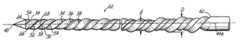
- FIG. 2is an enlarged elevational view of a portion of the endodontic instrument shown in FIG. 1;
- FIG. 3Ais an end view of an initial step in a grinding process used to form the endodontic instrument of FIGS. 1 and 2;
- FIG. 3Bis a view similar to FIG. 3A, but showing a later process step of grinding off at least a portion of one of the edges;
- FIG. 3Cis a view similar to FIG. 3B, but showing a further part of the same grinding process along the edge;
- FIG. 3Dis a view similar to FIG. 3C, but showing a grinding process performed on the opposite edge;
- FIG. 3Eis an end view of the finished ground blank prepared in accordance with FIGS. 3A-3D;
- FIG. 4is a side elevational view of the blank formed in accordance with FIGS. 3A-3D as viewed along the major diameter;
- FIG. 5is a side elevational view similar to FIG. 4, but illustrating the blank along the minor diameter
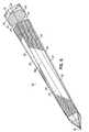
- FIG. 6is a perspective view of the blank ground in accordance with FIGS. 3A-3D;
- FIG. 7is an end view of an alternative wire blank constructed in accordance with the invention.
- FIG. 8is a side elevational view illustrating the wire blank of FIG. 7 along the minor diameter
- FIG. 9is a side elevational view similar to FIG. 8, but illustrating the wire blank along the major diameter
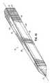
- FIG. 10is a perspective view of the wire blank illustrated in FIGS. 7-9;
- FIG. 11is an end view of another alternative embodiment of the invention.
- FIG. 12is a side elevational view of the wire blank shown in FIG. 11 and illustrated along the major diameter;
- FIG. 13is a side elevational view similar to FIG. 12, but illustrating the wire blank along the minor diameter
- FIG. 14is a perspective view illustrating the wire blank of FIGS. 11-13.
- an endodontic instrument 10 constructed in accordance with a preferred embodiment of the inventionis shown being used during a root canal procedure on a tooth 12 .
- Tooth 12includes root canals 14 , 16 and an upper interior portion 18 which has been initially opened using another instrument, such as a drill (not shown).
- Instrument 10includes a handle 20 for manual gripping by, for example, an endodontist and a working length 22 having helical flutes, as will be discussed in more detail below. Although these instruments are typically manipulated manually, the invention may be adapted to power-operated instruments as well. In a conventional manner, instrument 10 may be rotated in the direction of arrows “A” and reciprocated in the direction of arrow “B” by the endodontist to clean out and enlarge root canal 16 .
- respective flutesare formed by twisted surface portions 24 , 26 , 28 , 30 .
- These surface portions 24 , 26 , 28 , 30are defined between respective edges and surface portions 34 , 38 , 52 , 54 .
- the formation of surface portions 52 , 54will be further described with respect to FIGS. 3A-3E below.
- a minor diameter or cross-sectional dimension “d” and a major diameter or cross-sectional dimension “D”are evident along the working length 22 .
- Minor diameter “d”preferably remains substantially constant along working length 22 , while major diameter “D” becomes progressively larger in a direction extending from distal end 40 to proximal end 42 of working length 22 . Due to the substantially constant minor diameter “d” extending along the working length 22 , the flexibility of working length 22 is maintained generally constant along working length 22 in the preferred embodiment, however, this is not necessary to realize benefits of the invention. As will also be discussed below, minor diameter “d” may also have a taper along the working length 22 or along a portion or portions thereof so as to increase slightly in diameter from distal end 40 toward proximal end 42 . However, the rate of taper is preferably substantially less than the rate of taper of major diameter “D”. For example, the rate of taper for minor diameter “d” may be in the range of zero to about 0.06, while the rate of taper for major diameter “D” may be in the range of about 0.02 to about 0.14.
- FIGS. 3A-3Dillustrate a preferred method of manufacturing instrument 10 .
- a cylindrical wire 44has distal end 40 initially ground to a sharp point.
- Wire 44may be formed of any suitable material used for endodontic instruments of this type. As a few examples, such materials include superelastic materials such as NiTi, or other materials such as titanium, carbon steel or stainless steel.
- a grinding wheel 48is used to sequentially grind four longitudinally extending surface portions 24 , 26 , 28 , 30 along wire 44 . These become the flutes of the final, twisted instrument 10 . Specifically, as shown by the end view of wire 44 in FIGS. 3A and 3B, grinding wheel 48 is rotated as wire 44 translates with respect thereto along its center axis 44 a (FIG.
- Each longitudinal or lengthwise grinding stepforms one of the surface portions 24 , 26 , 28 , 30 .
- wire 44is indexed or rotated 90° before starting the grinding operation to form each successive surface portion 24 , 26 , 28 , 30 . This simultaneously forms respective edges 32 , 34 , 36 , 38 .
- wire 44may be ground along a working length of about 4 mm to about 23 mm.
- Wire 44is translated along grinding wheel 48 at a rate of about 100 in./min depending on the material and the size of wire 44 .
- grinding wheel 48is moved away from the center axis 44 a of wire 44 at a preferred rate of about 0.5 in./min. depending on the wire translation rate mentioned above and the desired taper. This rate may change for the different surface portions.
- the depth of cutmay be about 0.005 inch depending on the instrument size and material and the initial wire diameter is preferably 0.041 inch.
- a wire blank 44 ′is formed as shown in FIG.
- the major diameter, or largest diameter, of the blank at a given location along the working length 22is the distance between edges 34 and 38 or the equal distance between edges 32 and 36 .
- the minor diameter, or smallest diameter,is the distance between flats 24 and 28 or the equal distance between flats 26 and 30 .
- a new minor diameter “d”will be formed and this new minor diameter “d” will be smaller than the diameter between flats 24 , 28 or flats 26 , 30 along at least a portion of the working length 22 .
- edges 32 and 36have at least portions thereof ground off as flats 52 , 54 .
- These flats 52 , 54may extend completely along working length 22 or along one or more portions of working length 22 . As shown in FIG. 3E, these flats extend along a minor diameter “d” and, in this embodiment, are parallel to each other.
- each flat 52 or 54may be ground along wire blank 44 ′ and flats 52 and/or 54 may alternatively taper in a direction from proximal end 42 toward distal end 40 .
- each of the surface portions 24 , 26 , 28 , 30 , 52 , 54are shown as flat or planar surface portions, one or more of the surface portions may have an alternative surface configuration, such as a concave configuration, as long as the surface portion is generally flattened as opposed to being a sharp edge.
- a fully ground blank 60as shown in FIGS. 3E, 4 , 5 and 6 , is constructed and ready to be physically twisted by any suitable method known to those of skill in the art to form a final tissue removing instrument 10 as shown in FIG.
- ground blank 60will have a minor diameter “d”, as shown in FIG. 4, which may be substantially constant or slightly tapered along working length 22 .
- a major diameter “D”, as shown in FIG. 5,tapers more significantly as shown by dimensions T 1 , T 2 , T 3 which decrease in a direction from the proximal end (not shown) toward the distal end 40 .
- each surface portion 24 , 26 , 28 , 30gradually widens in a direction from distal end 40 toward proximal end 42 .
- the cross section of ground blank 60transforms from a relatively square cross section proximate distal end 40 to a six-sided cross section at proximal end 42 .
- FIGS. 7-10illustrate an alternative embodiment of the invention having a generally triangular-shaped cross section as will be appreciated from the end view of the ground blank 70 illustrated in FIG. 7 .
- This embodimentis ground in a similar manner to the process described in connection with FIGS. 3A-3D, except that a wire is initially formed into a triangular-shape, in cross section, by indexing the wire 120° after each lengthwise grinding operation to form respective lengthwise extending surface portions 72 , 74 , 76 .
- Surface portions 72 , 74 , 76ultimately become the helical flutes of the final twisted instrument (not shown).
- the distal end 77is again ground to a sharp point.
- a lengthwise cutting edge 80is formed between surface portions 72 , 74 .
- the two remaining opposite edges 82 a , 84 a extending along the ground blank 70are at least partially ground into parallel flat surface portions 82 , 84 as shown best in FIG. 7 .
- various changesmay be made from this preferred design including, for example, tapering the surface portions 82 , 84 , using only one surface portion 82 or 84 , and/or changing the surface configuration of the one or both of surface portions 82 , 84 .
- the wire blank 70Upon forming the fully ground wire blank 70 , the wire blank 70 is physically twisted such that the surface portions 72 , 74 , 76 , 82 , 84 and cutting edge 80 take on a helical shape, as in the first embodiment, but only having one cutting edge 80 and three helical flutes 72 , 74 , 76 .
- FIGS. 11-14illustrate another alternative embodiment of a fully ground wire blank 100 .
- like reference numerals to the first embodimentrefer to like elements, while numerals with prime marks (′) refer to somewhat modified elements as will be apparent from the drawings. Further repeated discussion of like or similar elements is not necessary.
- This wire blank 100is similar to the wire blank 60 illustrated in the first embodiment, except that the grinding operation along edges 32 , 36 starts at a length e from the distal end 40 as shown in FIG. 13 . Therefore, surface portions 52 ′, 54 ′ are formed and will increase the flexibility of the resulting instrument more at the proximal end of the working length while not increasing the flexibility of the working length toward the distal end 40 .
- the distal end portionmay already have sufficient flexibility and, therefore, may not need the additional grinding operation performed along the minor diameter as described in connection with this invention.
- the angle of grind of any of the surface portionsmay change along the working length. Ground blank 100 is physically twisted to form a final instrument as in the first and second embodiments.
Landscapes
- Health & Medical Sciences (AREA)
- Engineering & Computer Science (AREA)
- Mechanical Engineering (AREA)
- Oral & Maxillofacial Surgery (AREA)
- Epidemiology (AREA)
- Neurosurgery (AREA)
- Nuclear Medicine, Radiotherapy & Molecular Imaging (AREA)
- Surgery (AREA)
- Biomedical Technology (AREA)
- Dentistry (AREA)
- Neurology (AREA)
- Life Sciences & Earth Sciences (AREA)
- Animal Behavior & Ethology (AREA)
- General Health & Medical Sciences (AREA)
- Public Health (AREA)
- Veterinary Medicine (AREA)
- Dental Tools And Instruments Or Auxiliary Dental Instruments (AREA)
Abstract
Description
Claims (18)
Priority Applications (1)
| Application Number | Priority Date | Filing Date | Title |
|---|---|---|---|
| US09/972,104US6712611B2 (en) | 2001-10-05 | 2001-10-05 | Endodontic instrument with controlled flexibility and method of manufacturing same |
Applications Claiming Priority (1)
| Application Number | Priority Date | Filing Date | Title |
|---|---|---|---|
| US09/972,104US6712611B2 (en) | 2001-10-05 | 2001-10-05 | Endodontic instrument with controlled flexibility and method of manufacturing same |
Publications (2)
| Publication Number | Publication Date |
|---|---|
| US20030068597A1 US20030068597A1 (en) | 2003-04-10 |
| US6712611B2true US6712611B2 (en) | 2004-03-30 |
Family
ID=29216396
Family Applications (1)
| Application Number | Title | Priority Date | Filing Date |
|---|---|---|---|
| US09/972,104Expired - LifetimeUS6712611B2 (en) | 2001-10-05 | 2001-10-05 | Endodontic instrument with controlled flexibility and method of manufacturing same |
Country Status (1)
| Country | Link |
|---|---|
| US (1) | US6712611B2 (en) |
Cited By (16)
| Publication number | Priority date | Publication date | Assignee | Title |
|---|---|---|---|---|
| US20040146832A1 (en)* | 2003-01-13 | 2004-07-29 | Lampert Christopher J. | Endodontic instrument and instrument system |
| US20060210947A1 (en)* | 2003-01-13 | 2006-09-21 | Lampert Christopher J | Endodontic instrument and instrument system |
| US20070037117A1 (en)* | 2005-08-09 | 2007-02-15 | Andris Jaunberzins | Endodontic file combining active and passive cutting edges |
| US20090181341A1 (en)* | 2008-01-14 | 2009-07-16 | Lampert Chris J | Endodontic Instrument |
| US20100119990A1 (en)* | 2003-01-13 | 2010-05-13 | Lampert Christopher J | Endodontic instrument and instrument system |
| US20150216624A1 (en)* | 2013-06-20 | 2015-08-06 | Dentsply International Inc. | Endodontic instruments |
| US9662181B2 (en)* | 2005-04-08 | 2017-05-30 | Michael J. Scianamblo | Endodontic files with cross-cuts |
| US20170265964A1 (en)* | 2016-03-15 | 2017-09-21 | Essential Dental Systems, Inc. | Non-circular endodontic instruments |
| USD803399S1 (en) | 2006-04-10 | 2017-11-21 | Michael J. Scianamblo | Endodontic device |
| US10123850B2 (en) | 2013-01-30 | 2018-11-13 | Dentsply Sirona Inc. | Instrument for drilling dental root canals |
| US10130444B1 (en)* | 2017-07-14 | 2018-11-20 | Dentsply Sirona Inc. | Endodontic instrument |
| USD842474S1 (en) | 2017-10-20 | 2019-03-05 | Ormco Corporation | Endodontic file |
| US10543060B2 (en) | 2015-12-03 | 2020-01-28 | Ormco Corporation | Fluted endodontic file |
| US10595961B2 (en) | 2017-03-27 | 2020-03-24 | Michael J. Scianamblo | Endodontic instruments displaying compressibility |
| US20200229899A1 (en)* | 2019-01-17 | 2020-07-23 | Gebr. Brasseler Gmbh & Co Kg | Dental root canal instrument |
| US11267040B2 (en)* | 2014-09-09 | 2022-03-08 | Gold Standard Instruments, LLC | Method for forming an endodontic instrument or device |
Families Citing this family (10)
| Publication number | Priority date | Publication date | Assignee | Title |
|---|---|---|---|---|
| US20080213720A1 (en)* | 2003-05-13 | 2008-09-04 | Ultradent Products, Inc. | Endodontic instruments manufactured using chemical milling |
| US7743505B2 (en) | 2005-02-23 | 2010-06-29 | Ultradent Products, Inc. | Methods for manufacturing endodontic instruments from powdered metals |
| US7665212B2 (en)* | 2005-02-23 | 2010-02-23 | Ultradent Products, Inc. | Methods for manufacturing endodontic instruments |
| DE102007039700B4 (en)* | 2006-08-22 | 2014-12-04 | Stephan Gäbler | Root canal file |
| WO2010098385A1 (en)* | 2009-02-27 | 2010-09-02 | マニー株式会社 | Gutta-percha remover |
| FR2945438B1 (en)* | 2009-05-14 | 2012-04-20 | Neolix | ENDODONTIC INSTRUMENT HAVING AN AREA AT THE INTERSECTION OF TWO CUTTING SURFACES, THE ARETE HAVING A RELIEF SERIES. |
| FR2951067B1 (en)* | 2009-10-08 | 2012-04-06 | Micro Mega Int Mfg Sa | CHAIN REEL COMPRISING A PLURALITY OF HELICOIDAL CUTTING LIP |
| DE102014201899B4 (en)* | 2014-02-03 | 2023-04-27 | Gebr. Brasseler Gmbh & Co. Kg | dental instrument |
| JP7503958B2 (en)* | 2020-08-07 | 2024-06-21 | マニー株式会社 | Dental files |
| CN113081324B (en)* | 2021-03-29 | 2022-02-25 | 华中科技大学同济医学院附属协和医院 | Root canal file for preventing fracture and manufacturing method thereof |
Citations (11)
| Publication number | Priority date | Publication date | Assignee | Title |
|---|---|---|---|---|
| US1067015A (en)* | 1912-09-24 | 1913-07-08 | William W Fowler | Dental broach. |
| US4260379A (en) | 1979-05-17 | 1981-04-07 | Sybron Corporation | Endodontic instrument |
| US5106298A (en) | 1991-04-03 | 1992-04-21 | Heath Derek E | Endodontic dental instrument |
| US5380200A (en) | 1993-10-08 | 1995-01-10 | Quality Dental Products, Inc. | Endodontic instrument of predetermined flexibility |
| US5464362A (en) | 1991-11-05 | 1995-11-07 | Tulsa Dental Products, L.L.C. | Endodontic instrument |
| US5876202A (en)* | 1997-05-15 | 1999-03-02 | Jean-Claude Rouiller | Stagger cut teeth |
| US5882198A (en)* | 1997-03-28 | 1999-03-16 | Ormco Corporation | Endodontic instrument having enhanced compliance at the tip |
| US5984679A (en) | 1997-09-26 | 1999-11-16 | Ormco Corporation | Method of manufacturing superelastic endodontic files and files made therefrom |
| US6299445B1 (en)* | 1999-04-08 | 2001-10-09 | Ormco Corporation | Endodontic instrument, instrument blank and method of manufacture |
| US6382973B2 (en)* | 1999-12-17 | 2002-05-07 | Mani, Inc. | Dental root canal therapeutic instrument |
| US6409506B1 (en)* | 2000-05-01 | 2002-06-25 | Miltex Dental, Inc. | Endodontic instruments and process for producing the same |
- 2001
- 2001-10-05USUS09/972,104patent/US6712611B2/ennot_activeExpired - Lifetime
Patent Citations (13)
| Publication number | Priority date | Publication date | Assignee | Title |
|---|---|---|---|---|
| US1067015A (en)* | 1912-09-24 | 1913-07-08 | William W Fowler | Dental broach. |
| US4260379A (en) | 1979-05-17 | 1981-04-07 | Sybron Corporation | Endodontic instrument |
| US5106298A (en) | 1991-04-03 | 1992-04-21 | Heath Derek E | Endodontic dental instrument |
| US5464362A (en) | 1991-11-05 | 1995-11-07 | Tulsa Dental Products, L.L.C. | Endodontic instrument |
| US5628674A (en) | 1991-11-05 | 1997-05-13 | Tulsa Dental Products, L.L.C. | Endodontic instrument |
| US5380200A (en) | 1993-10-08 | 1995-01-10 | Quality Dental Products, Inc. | Endodontic instrument of predetermined flexibility |
| US5882198A (en)* | 1997-03-28 | 1999-03-16 | Ormco Corporation | Endodontic instrument having enhanced compliance at the tip |
| US5876202A (en)* | 1997-05-15 | 1999-03-02 | Jean-Claude Rouiller | Stagger cut teeth |
| US5984679A (en) | 1997-09-26 | 1999-11-16 | Ormco Corporation | Method of manufacturing superelastic endodontic files and files made therefrom |
| US6315558B1 (en)* | 1997-09-26 | 2001-11-13 | Ormco Corporation | Method of manufacturing superelastic endodontic files and files made therefrom |
| US6299445B1 (en)* | 1999-04-08 | 2001-10-09 | Ormco Corporation | Endodontic instrument, instrument blank and method of manufacture |
| US6382973B2 (en)* | 1999-12-17 | 2002-05-07 | Mani, Inc. | Dental root canal therapeutic instrument |
| US6409506B1 (en)* | 2000-05-01 | 2002-06-25 | Miltex Dental, Inc. | Endodontic instruments and process for producing the same |
Non-Patent Citations (3)
| Title |
|---|
| Dr. Edgar Schäfer, Relationship Between Design Features of Endodontic Instruments and Their Properties, Part 1: Cutting Efficiency, Article, 4 pgs., undated. |
| Dr. Edgar Schäfer, Relationship Between Design Features of Endodontic Instruments and Their Properties, Part 2: Instrumentation of Curved Canals, Article, 4 pgs., undated. |
| Kerr Corporation, New Kerr K-Flex Instrument, Brochure, 7 pgs., Feb. 1981. |
Cited By (30)
| Publication number | Priority date | Publication date | Assignee | Title |
|---|---|---|---|---|
| US20100119990A1 (en)* | 2003-01-13 | 2010-05-13 | Lampert Christopher J | Endodontic instrument and instrument system |
| US7338284B2 (en) | 2003-01-13 | 2008-03-04 | Lampert Christopher J | Endodontic instrument and instrument system |
| US20040146832A1 (en)* | 2003-01-13 | 2004-07-29 | Lampert Christopher J. | Endodontic instrument and instrument system |
| US20060210947A1 (en)* | 2003-01-13 | 2006-09-21 | Lampert Christopher J | Endodontic instrument and instrument system |
| US11478331B2 (en) | 2005-04-08 | 2022-10-25 | Scianamblo Michael J | Endodontic instruments with offset centers of mass |
| US10568715B2 (en) | 2005-04-08 | 2020-02-25 | Michael J. Scianamblo | Endodontic instruments with offset centers of mass |
| US11607290B2 (en) | 2005-04-08 | 2023-03-21 | Michael J. Scianamblo | Endodontic instruments |
| US9662181B2 (en)* | 2005-04-08 | 2017-05-30 | Michael J. Scianamblo | Endodontic files with cross-cuts |
| US20070037117A1 (en)* | 2005-08-09 | 2007-02-15 | Andris Jaunberzins | Endodontic file combining active and passive cutting edges |
| US7766657B2 (en)* | 2005-08-09 | 2010-08-03 | Andris Jaunberzins | Endodontic file combining active and passive cutting edges |
| US8727772B2 (en) | 2005-08-09 | 2014-05-20 | William B. Johnson | Endodontic file combining active and passive cutting edges |
| USD803399S1 (en) | 2006-04-10 | 2017-11-21 | Michael J. Scianamblo | Endodontic device |
| WO2007143697A3 (en)* | 2006-06-06 | 2008-07-31 | Christopher J Lampert | Endodontic instrument and instrument system |
| US20090181341A1 (en)* | 2008-01-14 | 2009-07-16 | Lampert Chris J | Endodontic Instrument |
| US10123850B2 (en) | 2013-01-30 | 2018-11-13 | Dentsply Sirona Inc. | Instrument for drilling dental root canals |
| US11523880B2 (en)* | 2013-01-30 | 2022-12-13 | Dentsply Sirona Inc. | Instrument for drilling dental root canals |
| US20210145540A1 (en)* | 2013-01-30 | 2021-05-20 | Dentsply Sirona Inc. | Instrument for drilling dental root canals |
| US10966801B2 (en)* | 2013-06-20 | 2021-04-06 | Dentsply Sirona Inc. | Endodontic instruments |
| US20150216624A1 (en)* | 2013-06-20 | 2015-08-06 | Dentsply International Inc. | Endodontic instruments |
| US9901418B2 (en)* | 2013-06-20 | 2018-02-27 | DENTSPLY SIRONA, Inc. | Endodontic instruments |
| US11267040B2 (en)* | 2014-09-09 | 2022-03-08 | Gold Standard Instruments, LLC | Method for forming an endodontic instrument or device |
| US10543060B2 (en) | 2015-12-03 | 2020-01-28 | Ormco Corporation | Fluted endodontic file |
| US10561475B2 (en)* | 2016-03-15 | 2020-02-18 | Essential Dental Systems, Inc. | Non-circular endodontic instruments |
| US20170265964A1 (en)* | 2016-03-15 | 2017-09-21 | Essential Dental Systems, Inc. | Non-circular endodontic instruments |
| US10595961B2 (en) | 2017-03-27 | 2020-03-24 | Michael J. Scianamblo | Endodontic instruments displaying compressibility |
| US11944513B2 (en) | 2017-03-27 | 2024-04-02 | Michael J. Scianamblo | Endodontic instruments displaying compressibility |
| US10130444B1 (en)* | 2017-07-14 | 2018-11-20 | Dentsply Sirona Inc. | Endodontic instrument |
| USD842474S1 (en) | 2017-10-20 | 2019-03-05 | Ormco Corporation | Endodontic file |
| US20200229899A1 (en)* | 2019-01-17 | 2020-07-23 | Gebr. Brasseler Gmbh & Co Kg | Dental root canal instrument |
| US12357425B2 (en)* | 2019-01-17 | 2025-07-15 | Gebr. Brasseler Gmbh & Co. Kg | Dental root canal instrument |
Also Published As
| Publication number | Publication date |
|---|---|
| US20030068597A1 (en) | 2003-04-10 |
Similar Documents
| Publication | Publication Date | Title |
|---|---|---|
| US6712611B2 (en) | Endodontic instrument with controlled flexibility and method of manufacturing same | |
| US6299445B1 (en) | Endodontic instrument, instrument blank and method of manufacture | |
| EP1752109B1 (en) | Endodontic file combining active and passive cutting edges | |
| US6293794B1 (en) | Endodontic instrument having regressive conicity | |
| US5902106A (en) | Endodontic dental instrument | |
| EP1086659B1 (en) | Endodontic treatment system | |
| US5762497A (en) | Endodontic dental instrument | |
| US7094056B2 (en) | Endodontic instrument having reversed helix | |
| EP1531752B1 (en) | Endodontic instrument | |
| EP1184004B1 (en) | Endodontic instrument | |
| JPH0510943B2 (en) | ||
| JPH09253092A (en) | Root canal drilling method and instrument set for performing the method | |
| US20040191723A1 (en) | Endodontic instrument | |
| US8439682B1 (en) | Set of endodontic instruments | |
| JPH09253093A (en) | Instruments for drilling root canals | |
| US20120208146A1 (en) | Fluted reamer comprising a plurality of helical cutting lips | |
| JP2004522524A (en) | Multiple tapered dental file | |
| KR100958454B1 (en) | Root canal file, and root canal instrument | |
| EP2140828A2 (en) | Dental file with improved tip configuration | |
| AU2002242110A1 (en) | Multi-tapered dental files |
Legal Events
| Date | Code | Title | Description |
|---|---|---|---|
| AS | Assignment | Owner name:ORMCO CORPORATION, CALIFORNIA Free format text:ASSIGNMENT OF ASSIGNORS INTEREST;ASSIGNOR:GARMAN, GARY T.;REEL/FRAME:012421/0199 Effective date:20011119 | |
| AS | Assignment | Owner name:CREDIT SUISSE FIRST BOSTON, NEW YORK Free format text:SECURITY AGREEMENT;ASSIGNOR:ORMCO CORPORATION;REEL/FRAME:014137/0795 Effective date:20020606 | |
| STCF | Information on status: patent grant | Free format text:PATENTED CASE | |
| CC | Certificate of correction | ||
| FPAY | Fee payment | Year of fee payment:4 | |
| REMI | Maintenance fee reminder mailed | ||
| FPAY | Fee payment | Year of fee payment:8 | |
| FPAY | Fee payment | Year of fee payment:12 | |
| AS | Assignment | Owner name:BANK OF AMERICA, N.A., AS ADMINISTRATIVE AGENT, NORTH CAROLINA Free format text:SECURITY INTEREST;ASSIGNOR:ORMCO CORPORATION;REEL/FRAME:052617/0617 Effective date:20200506 | |
| AS | Assignment | Owner name:ORMCO CORPORATION, CALIFORNIA Free format text:RELEASE BY SECURED PARTY;ASSIGNOR:BANK OF AMERICA, N.A., AS ADMINISTRATIVE AGENT;REEL/FRAME:055886/0080 Effective date:20210408 |