US6712486B1 - Mounting arrangement for light emitting diodes - Google Patents
Mounting arrangement for light emitting diodesDownload PDFInfo
- Publication number
- US6712486B1 US6712486B1US09/693,548US69354800AUS6712486B1US 6712486 B1US6712486 B1US 6712486B1US 69354800 AUS69354800 AUS 69354800AUS 6712486 B1US6712486 B1US 6712486B1
- Authority
- US
- United States
- Prior art keywords
- led
- leds
- contacts
- module
- led module
- Prior art date
- Legal status (The legal status is an assumption and is not a legal conclusion. Google has not performed a legal analysis and makes no representation as to the accuracy of the status listed.)
- Expired - Lifetime
Links
- 238000005286illuminationMethods0.000claimsabstractdescription33
- 239000000463materialSubstances0.000claimsdescription16
- 229910052782aluminiumInorganic materials0.000claimsdescription8
- XAGFODPZIPBFFR-UHFFFAOYSA-NaluminiumChemical compound[Al]XAGFODPZIPBFFR-UHFFFAOYSA-N0.000claimsdescription8
- 238000004891communicationMethods0.000claimsdescription8
- 239000004593EpoxySubstances0.000claimsdescription4
- 239000011248coating agentSubstances0.000claimsdescription4
- 238000000576coating methodMethods0.000claimsdescription4
- 229910052751metalInorganic materials0.000claimsdescription3
- 239000002184metalSubstances0.000claimsdescription3
- 230000000295complement effectEffects0.000claims1
- 230000003247decreasing effectEffects0.000abstract1
- RYGMFSIKBFXOCR-UHFFFAOYSA-NCopperChemical compound[Cu]RYGMFSIKBFXOCR-UHFFFAOYSA-N0.000description6
- 229910052802copperInorganic materials0.000description6
- 239000010949copperSubstances0.000description6
- 239000000919ceramicSubstances0.000description5
- 238000004519manufacturing processMethods0.000description5
- 239000004020conductorSubstances0.000description3
- JBRZTFJDHDCESZ-UHFFFAOYSA-NAsGaChemical compound[As]#[Ga]JBRZTFJDHDCESZ-UHFFFAOYSA-N0.000description2
- 229910001218Gallium arsenideInorganic materials0.000description2
- 239000000853adhesiveSubstances0.000description2
- 230000001070adhesive effectEffects0.000description2
- 230000000694effectsEffects0.000description2
- 230000003760hair shineEffects0.000description2
- 238000009434installationMethods0.000description2
- 230000007774longtermEffects0.000description2
- 238000000034methodMethods0.000description2
- 238000012986modificationMethods0.000description2
- 230000004048modificationEffects0.000description2
- 229910052754neonInorganic materials0.000description2
- GKAOGPIIYCISHV-UHFFFAOYSA-Nneon atomChemical compound[Ne]GKAOGPIIYCISHV-UHFFFAOYSA-N0.000description2
- 238000004806packaging method and processMethods0.000description2
- 239000004033plasticSubstances0.000description2
- 229920003023plasticPolymers0.000description2
- 229920001296polysiloxanePolymers0.000description2
- 238000007493shaping processMethods0.000description2
- FRWYFWZENXDZMU-UHFFFAOYSA-N2-iodoquinolineChemical compoundC1=CC=CC2=NC(I)=CC=C21FRWYFWZENXDZMU-UHFFFAOYSA-N0.000description1
- 229910005540GaPInorganic materials0.000description1
- 230000003466anti-cipated effectEffects0.000description1
- LTPBRCUWZOMYOC-UHFFFAOYSA-Nberyllium oxideInorganic materialsO=[Be]LTPBRCUWZOMYOC-UHFFFAOYSA-N0.000description1
- 229910010293ceramic materialInorganic materials0.000description1
- PMHQVHHXPFUNSP-UHFFFAOYSA-Mcopper(1+);methylsulfanylmethane;bromideChemical compoundBr[Cu].CSCPMHQVHHXPFUNSP-UHFFFAOYSA-M0.000description1
- 238000006073displacement reactionMethods0.000description1
- 238000010292electrical insulationMethods0.000description1
- 239000004744fabricSubstances0.000description1
- 235000020280flat whiteNutrition0.000description1
- 238000009413insulationMethods0.000description1
- 239000003550markerSubstances0.000description1
- 230000003287optical effectEffects0.000description1
- 239000004417polycarbonateSubstances0.000description1
- 229920000515polycarbonatePolymers0.000description1
- 239000011347resinSubstances0.000description1
- 229920005989resinPolymers0.000description1
- 230000000717retained effectEffects0.000description1
- 239000004065semiconductorSubstances0.000description1
- 229910000679solderInorganic materials0.000description1
- 230000000007visual effectEffects0.000description1
- 238000003466weldingMethods0.000description1
Images


Classifications
- F—MECHANICAL ENGINEERING; LIGHTING; HEATING; WEAPONS; BLASTING
- F21—LIGHTING
- F21V—FUNCTIONAL FEATURES OR DETAILS OF LIGHTING DEVICES OR SYSTEMS THEREOF; STRUCTURAL COMBINATIONS OF LIGHTING DEVICES WITH OTHER ARTICLES, NOT OTHERWISE PROVIDED FOR
- F21V29/00—Protecting lighting devices from thermal damage; Cooling or heating arrangements specially adapted for lighting devices or systems
- F21V29/50—Cooling arrangements
- F21V29/70—Cooling arrangements characterised by passive heat-dissipating elements, e.g. heat-sinks
- A—HUMAN NECESSITIES
- A47—FURNITURE; DOMESTIC ARTICLES OR APPLIANCES; COFFEE MILLS; SPICE MILLS; SUCTION CLEANERS IN GENERAL
- A47C—CHAIRS; SOFAS; BEDS
- A47C7/00—Parts, details, or accessories of chairs or stools
- A47C7/62—Accessories for chairs
- A47C7/72—Adaptations for incorporating lamps, radio sets, bars, telephones, ventilation, heating or cooling arrangements or the like
- A47C7/725—Adaptations for incorporating lamps, radio sets, bars, telephones, ventilation, heating or cooling arrangements or the like for illumination, e.g. lamps
- F—MECHANICAL ENGINEERING; LIGHTING; HEATING; WEAPONS; BLASTING
- F21—LIGHTING
- F21K—NON-ELECTRIC LIGHT SOURCES USING LUMINESCENCE; LIGHT SOURCES USING ELECTROCHEMILUMINESCENCE; LIGHT SOURCES USING CHARGES OF COMBUSTIBLE MATERIAL; LIGHT SOURCES USING SEMICONDUCTOR DEVICES AS LIGHT-GENERATING ELEMENTS; LIGHT SOURCES NOT OTHERWISE PROVIDED FOR
- F21K9/00—Light sources using semiconductor devices as light-generating elements, e.g. using light-emitting diodes [LED] or lasers
- F21K9/60—Optical arrangements integrated in the light source, e.g. for improving the colour rendering index or the light extraction
- F—MECHANICAL ENGINEERING; LIGHTING; HEATING; WEAPONS; BLASTING
- F21—LIGHTING
- F21K—NON-ELECTRIC LIGHT SOURCES USING LUMINESCENCE; LIGHT SOURCES USING ELECTROCHEMILUMINESCENCE; LIGHT SOURCES USING CHARGES OF COMBUSTIBLE MATERIAL; LIGHT SOURCES USING SEMICONDUCTOR DEVICES AS LIGHT-GENERATING ELEMENTS; LIGHT SOURCES NOT OTHERWISE PROVIDED FOR
- F21K9/00—Light sources using semiconductor devices as light-generating elements, e.g. using light-emitting diodes [LED] or lasers
- F21K9/90—Methods of manufacture
- F—MECHANICAL ENGINEERING; LIGHTING; HEATING; WEAPONS; BLASTING
- F21—LIGHTING
- F21V—FUNCTIONAL FEATURES OR DETAILS OF LIGHTING DEVICES OR SYSTEMS THEREOF; STRUCTURAL COMBINATIONS OF LIGHTING DEVICES WITH OTHER ARTICLES, NOT OTHERWISE PROVIDED FOR
- F21V19/00—Fastening of light sources or lamp holders
- F21V19/001—Fastening of light sources or lamp holders the light sources being semiconductors devices, e.g. LEDs
- F—MECHANICAL ENGINEERING; LIGHTING; HEATING; WEAPONS; BLASTING
- F21—LIGHTING
- F21V—FUNCTIONAL FEATURES OR DETAILS OF LIGHTING DEVICES OR SYSTEMS THEREOF; STRUCTURAL COMBINATIONS OF LIGHTING DEVICES WITH OTHER ARTICLES, NOT OTHERWISE PROVIDED FOR
- F21V29/00—Protecting lighting devices from thermal damage; Cooling or heating arrangements specially adapted for lighting devices or systems
- F21V29/50—Cooling arrangements
- F21V29/502—Cooling arrangements characterised by the adaptation for cooling of specific components
- F21V29/507—Cooling arrangements characterised by the adaptation for cooling of specific components of means for protecting lighting devices from damage, e.g. housings
- F—MECHANICAL ENGINEERING; LIGHTING; HEATING; WEAPONS; BLASTING
- F21—LIGHTING
- F21V—FUNCTIONAL FEATURES OR DETAILS OF LIGHTING DEVICES OR SYSTEMS THEREOF; STRUCTURAL COMBINATIONS OF LIGHTING DEVICES WITH OTHER ARTICLES, NOT OTHERWISE PROVIDED FOR
- F21V29/00—Protecting lighting devices from thermal damage; Cooling or heating arrangements specially adapted for lighting devices or systems
- F21V29/50—Cooling arrangements
- F21V29/70—Cooling arrangements characterised by passive heat-dissipating elements, e.g. heat-sinks
- F21V29/74—Cooling arrangements characterised by passive heat-dissipating elements, e.g. heat-sinks with fins or blades
- G—PHYSICS
- G09—EDUCATION; CRYPTOGRAPHY; DISPLAY; ADVERTISING; SEALS
- G09F—DISPLAYING; ADVERTISING; SIGNS; LABELS OR NAME-PLATES; SEALS
- G09F13/00—Illuminated signs; Luminous advertising
- G09F13/20—Illuminated signs; Luminous advertising with luminescent surfaces or parts
- G09F13/22—Illuminated signs; Luminous advertising with luminescent surfaces or parts electroluminescent
- G—PHYSICS
- G09—EDUCATION; CRYPTOGRAPHY; DISPLAY; ADVERTISING; SEALS
- G09F—DISPLAYING; ADVERTISING; SIGNS; LABELS OR NAME-PLATES; SEALS
- G09F9/00—Indicating arrangements for variable information in which the information is built-up on a support by selection or combination of individual elements
- G09F9/30—Indicating arrangements for variable information in which the information is built-up on a support by selection or combination of individual elements in which the desired character or characters are formed by combining individual elements
- G09F9/33—Indicating arrangements for variable information in which the information is built-up on a support by selection or combination of individual elements in which the desired character or characters are formed by combining individual elements being semiconductor devices, e.g. diodes
- H—ELECTRICITY
- H05—ELECTRIC TECHNIQUES NOT OTHERWISE PROVIDED FOR
- H05K—PRINTED CIRCUITS; CASINGS OR CONSTRUCTIONAL DETAILS OF ELECTRIC APPARATUS; MANUFACTURE OF ASSEMBLAGES OF ELECTRICAL COMPONENTS
- H05K1/00—Printed circuits
- H05K1/02—Details
- H05K1/0201—Thermal arrangements, e.g. for cooling, heating or preventing overheating
- H05K1/0203—Cooling of mounted components
- H—ELECTRICITY
- H05—ELECTRIC TECHNIQUES NOT OTHERWISE PROVIDED FOR
- H05K—PRINTED CIRCUITS; CASINGS OR CONSTRUCTIONAL DETAILS OF ELECTRIC APPARATUS; MANUFACTURE OF ASSEMBLAGES OF ELECTRICAL COMPONENTS
- H05K3/00—Apparatus or processes for manufacturing printed circuits
- H05K3/30—Assembling printed circuits with electric components, e.g. with resistor
- H05K3/32—Assembling printed circuits with electric components, e.g. with resistor electrically connecting electric components or wires to printed circuits
- F—MECHANICAL ENGINEERING; LIGHTING; HEATING; WEAPONS; BLASTING
- F21—LIGHTING
- F21V—FUNCTIONAL FEATURES OR DETAILS OF LIGHTING DEVICES OR SYSTEMS THEREOF; STRUCTURAL COMBINATIONS OF LIGHTING DEVICES WITH OTHER ARTICLES, NOT OTHERWISE PROVIDED FOR
- F21V29/00—Protecting lighting devices from thermal damage; Cooling or heating arrangements specially adapted for lighting devices or systems
- F21V29/85—Protecting lighting devices from thermal damage; Cooling or heating arrangements specially adapted for lighting devices or systems characterised by the material
- F21V29/89—Metals
- F—MECHANICAL ENGINEERING; LIGHTING; HEATING; WEAPONS; BLASTING
- F21—LIGHTING
- F21V—FUNCTIONAL FEATURES OR DETAILS OF LIGHTING DEVICES OR SYSTEMS THEREOF; STRUCTURAL COMBINATIONS OF LIGHTING DEVICES WITH OTHER ARTICLES, NOT OTHERWISE PROVIDED FOR
- F21V7/00—Reflectors for light sources
- F21V7/0025—Combination of two or more reflectors for a single light source
- F—MECHANICAL ENGINEERING; LIGHTING; HEATING; WEAPONS; BLASTING
- F21—LIGHTING
- F21V—FUNCTIONAL FEATURES OR DETAILS OF LIGHTING DEVICES OR SYSTEMS THEREOF; STRUCTURAL COMBINATIONS OF LIGHTING DEVICES WITH OTHER ARTICLES, NOT OTHERWISE PROVIDED FOR
- F21V7/00—Reflectors for light sources
- F21V7/005—Reflectors for light sources with an elongated shape to cooperate with linear light sources
- F—MECHANICAL ENGINEERING; LIGHTING; HEATING; WEAPONS; BLASTING
- F21—LIGHTING
- F21Y—INDEXING SCHEME ASSOCIATED WITH SUBCLASSES F21K, F21L, F21S and F21V, RELATING TO THE FORM OR THE KIND OF THE LIGHT SOURCES OR OF THE COLOUR OF THE LIGHT EMITTED
- F21Y2103/00—Elongate light sources, e.g. fluorescent tubes
- F21Y2103/10—Elongate light sources, e.g. fluorescent tubes comprising a linear array of point-like light-generating elements
- F—MECHANICAL ENGINEERING; LIGHTING; HEATING; WEAPONS; BLASTING
- F21—LIGHTING
- F21Y—INDEXING SCHEME ASSOCIATED WITH SUBCLASSES F21K, F21L, F21S and F21V, RELATING TO THE FORM OR THE KIND OF THE LIGHT SOURCES OR OF THE COLOUR OF THE LIGHT EMITTED
- F21Y2115/00—Light-generating elements of semiconductor light sources
- F21Y2115/10—Light-emitting diodes [LED]
- H—ELECTRICITY
- H05—ELECTRIC TECHNIQUES NOT OTHERWISE PROVIDED FOR
- H05K—PRINTED CIRCUITS; CASINGS OR CONSTRUCTIONAL DETAILS OF ELECTRIC APPARATUS; MANUFACTURE OF ASSEMBLAGES OF ELECTRICAL COMPONENTS
- H05K2201/00—Indexing scheme relating to printed circuits covered by H05K1/00
- H05K2201/10—Details of components or other objects attached to or integrated in a printed circuit board
- H05K2201/10007—Types of components
- H05K2201/10106—Light emitting diode [LED]
- H—ELECTRICITY
- H05—ELECTRIC TECHNIQUES NOT OTHERWISE PROVIDED FOR
- H05K—PRINTED CIRCUITS; CASINGS OR CONSTRUCTIONAL DETAILS OF ELECTRIC APPARATUS; MANUFACTURE OF ASSEMBLAGES OF ELECTRICAL COMPONENTS
- H05K2201/00—Indexing scheme relating to printed circuits covered by H05K1/00
- H05K2201/10—Details of components or other objects attached to or integrated in a printed circuit board
- H05K2201/10431—Details of mounted components
- H05K2201/10439—Position of a single component
- H05K2201/10446—Mounted on an edge
- H—ELECTRICITY
- H05—ELECTRIC TECHNIQUES NOT OTHERWISE PROVIDED FOR
- H05K—PRINTED CIRCUITS; CASINGS OR CONSTRUCTIONAL DETAILS OF ELECTRIC APPARATUS; MANUFACTURE OF ASSEMBLAGES OF ELECTRICAL COMPONENTS
- H05K2201/00—Indexing scheme relating to printed circuits covered by H05K1/00
- H05K2201/10—Details of components or other objects attached to or integrated in a printed circuit board
- H05K2201/10431—Details of mounted components
- H05K2201/10598—Means for fastening a component, a casing or a heat sink whereby a pressure is exerted on the component towards the PCB
- H—ELECTRICITY
- H05—ELECTRIC TECHNIQUES NOT OTHERWISE PROVIDED FOR
- H05K—PRINTED CIRCUITS; CASINGS OR CONSTRUCTIONAL DETAILS OF ELECTRIC APPARATUS; MANUFACTURE OF ASSEMBLAGES OF ELECTRICAL COMPONENTS
- H05K3/00—Apparatus or processes for manufacturing printed circuits
- H05K3/0058—Laminating printed circuit boards onto other substrates, e.g. metallic substrates
- H05K3/0061—Laminating printed circuit boards onto other substrates, e.g. metallic substrates onto a metallic substrate, e.g. a heat sink
- Y—GENERAL TAGGING OF NEW TECHNOLOGICAL DEVELOPMENTS; GENERAL TAGGING OF CROSS-SECTIONAL TECHNOLOGIES SPANNING OVER SEVERAL SECTIONS OF THE IPC; TECHNICAL SUBJECTS COVERED BY FORMER USPC CROSS-REFERENCE ART COLLECTIONS [XRACs] AND DIGESTS
- Y10—TECHNICAL SUBJECTS COVERED BY FORMER USPC
- Y10S—TECHNICAL SUBJECTS COVERED BY FORMER USPC CROSS-REFERENCE ART COLLECTIONS [XRACs] AND DIGESTS
- Y10S362/00—Illumination
- Y10S362/80—Light emitting diode
- Y—GENERAL TAGGING OF NEW TECHNOLOGICAL DEVELOPMENTS; GENERAL TAGGING OF CROSS-SECTIONAL TECHNOLOGIES SPANNING OVER SEVERAL SECTIONS OF THE IPC; TECHNICAL SUBJECTS COVERED BY FORMER USPC CROSS-REFERENCE ART COLLECTIONS [XRACs] AND DIGESTS
- Y10—TECHNICAL SUBJECTS COVERED BY FORMER USPC
- Y10T—TECHNICAL SUBJECTS COVERED BY FORMER US CLASSIFICATION
- Y10T29/00—Metal working
- Y10T29/49—Method of mechanical manufacture
- Y10T29/49002—Electrical device making
- Y10T29/49117—Conductor or circuit manufacturing
- Y10T29/49124—On flat or curved insulated base, e.g., printed circuit, etc.
- Y10T29/4913—Assembling to base an electrical component, e.g., capacitor, etc.
- Y10T29/49133—Assembling to base an electrical component, e.g., capacitor, etc. with component orienting
- Y—GENERAL TAGGING OF NEW TECHNOLOGICAL DEVELOPMENTS; GENERAL TAGGING OF CROSS-SECTIONAL TECHNOLOGIES SPANNING OVER SEVERAL SECTIONS OF THE IPC; TECHNICAL SUBJECTS COVERED BY FORMER USPC CROSS-REFERENCE ART COLLECTIONS [XRACs] AND DIGESTS
- Y10—TECHNICAL SUBJECTS COVERED BY FORMER USPC
- Y10T—TECHNICAL SUBJECTS COVERED BY FORMER US CLASSIFICATION
- Y10T29/00—Metal working
- Y10T29/49—Method of mechanical manufacture
- Y10T29/49826—Assembling or joining
Definitions
- the present inventionis in the field of light emitting diode (LED) lighting devices and more particularly in the field of an LED lighting module having heat transfer properties that improve the efficiency and performance of LEDs.
- LEDlight emitting diode
- LEDsLight emitting diodes
- the compactness, efficiency and long life of LEDsis particularly desirable and makes LEDs well suited for many applications.
- a limitation of LEDs'is that they typically cannot maintain a long-term brightness that is acceptable for middle to large-scale illumination applications. Instead, more traditional incandescent or gas-filled light bulbs are often used.
- An increase of the electrical current supplied to an LEDgenerally increases the brightness of the light emitted by the LED.
- increased currentalso increases the juncture temperature of the LED.
- Increased juncture temperaturemay reduce the efficiency and the lifetime of the LED. For example, it has been noted that for every 10° C. increase in temperature, silicone and gallium arsenide lifetime drops by a factor of 2.5-3. LEDs are often constructed of semiconductor materials that share many similar properties with silicone and gallium arsenide.
- an LED modulefor mounting on a heat conducting surface that is substantially larger than the module.
- the modulecomprises a plurality of LED packages and a circuit board.
- Each LED packagehas an LED and at least one lead.
- the circuit boardcomprises a thin dielectric sheet and a plurality of electrically-conductive contacts on a first side of the dielectric sheet. Each of the contacts is configured to mount a lead of an LED package such that the LEDs are connected in series.
- a heat conductive plateis disposed on a second side of the dielectric sheet.
- the platehas a first side which is in thermal communication with the contacts through the dielectric sheet.
- the first side of the platehas a surface area substantially larger than a contact area between the contacts and the dielectric sheet.
- the platehas a second side adapted to provide thermal contact with the heat conducting surface. In this manner, heat is transferred from the module to the heat conducting surface.
- a modular lighting apparatusfor conducting heat away from a light source of the apparatus.
- the apparatuscomprises a plurality of LEDs and a circuit board.
- the circuit boardhas a main body and a plurality of electrically conductive contacts.
- Each of the LEDselectrically communicates with at least one of the contacts in a manner so that the LEDs are configured in a series array.
- Each of the LEDselectrically communicates with corresponding contacts at an attachment area defined on each contact.
- An overall surface of the contactis substantially larger than the attachment area.
- the plurality of contactsare arranged adjacent a first side of the main body and are in thermal communication with the first side of the main body.
- the main bodyelectrically insulates the plurality of contacts relative to one another.
- FIG. 1is a perspective view of an LED module having features in accordance with the present invention.
- FIG. 2is a schematic side view of a typical pre-packaged LED lamp.
- FIG. 3is a top plan view of the LED module of FIG. 1 .
- FIG. 4is a side plan view of the apparatus of FIG. 3 .
- FIG. 5is a close-up side view of the apparatus of FIG. 3 mounted on a heat conductive member.
- FIG. 6is another sectional side view of the apparatus of FIG. 3 mounted onto a heat conductive flat surface.
- FIG. 7is a side plan view of an LED module having features in accordance with another embodiment of the present invention.
- FIG. 8is a side plan view of another LED module having features in accordance with yet another embodiment of the present invention.
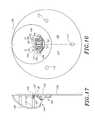
- FIG. 9is a perspective view of an illumination apparatus having features in accordance with the present invention.
- FIG. 10is a side view of the apparatus of FIG. 9 .
- FIG. 11is a bottom view of the apparatus of FIG. 9 .
- FIG. 12is a top view of the apparatus of FIG. 9 .
- FIG. 13is a schematic view of the apparatus of FIG. 9 mounted on a theater seat row end.
- FIG. 14is a side view of the apparatus of FIG. 13 showing the mounting orientation.
- FIG. 15is a side view of a mounting barb.
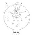
- FIG. 16is a front plan view of the illumination apparatus of FIG. 9 .
- FIG. 17is a cutaway side plan view of the apparatus of FIG. 20 .
- FIG. 18is a schematic plan view of a heat sink base plate.
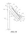
- FIG. 19is a close-up side sectional view of an LED module mounted on a mount tab of a base plate.
- FIG. 20is a plan view of a lens for use with the apparatus of FIG. 9 .
- FIG. 21is a perspective view of a channel illumination apparatus incorporating LED modules having features in accordance with the present invention.
- FIG. 22is a close-up side view of an LED module mounted on a mount tab.
- FIG. 23is a partial view of a wall of the apparatus of FIG. 21, taken along line 23 — 23 .
- FIG. 24is a top view of an LED module mounted to a wall of the apparatus of FIG. 21 .
- FIG. 25is a top view of an alternative embodiment of an LED module mounted to a wall of the apparatus of FIG. 21 .
- FIG. 26Ais a side view of an alternative embodiment of a lighting module being mounted onto a channel illumination apparatus wall member.
- FIG. 26Bshows the apparatus of the arrangement of FIG. 26A with the lighting module installed.
- FIG. 26Cshows the arrangement of FIG. 26B with a lens installed on the wall member.
- FIG. 26Dshows a side view of an alternative embodiment of a lighting module installed on a channel illumination apparatus wall member.
- the LED module 30includes five pre-packaged LEDs 32 arranged on one side of the module 30 . It is to be understood, however, that LED modules having features in accordance with the present invention can be constructed having any number of LEDs 32 mounted in any desired configuration.
- a typical pre-packaged LED 32includes a diode chip 34 encased within a resin body 36 .
- the body 36typically has a focusing lens portion 38 .
- a negative lead 40connects to an anode side 42 of the diode chip 34 and a positive lead 44 connects to a cathode side 46 of the diode chip 34 .
- the positive lead 44preferably includes a reflector portion 48 to help direct light from the diode 34 to the lens portion 38 .
- the LED module 30preferably comprises the five pre-packaged LED lamps 32 mounted in a linear array on a circuit board 50 and electrically connected in series.
- the illustrated embodimentemploys pre-packaged aluminum indium-gallium phosphide (AlInGaP) LED lamps 32 such as model HLMT-PL00, which is available from Hewlett Packard.
- AlInGaPaluminum indium-gallium phosphide
- each of the pre-packaged LEDsis substantially identical so that they emit the same color of light. It is to be understood, however, that nonidentical LEDs may be used to achieve certain desired lighting effects.
- the illustrated circuit board 50preferably is about 0.05 inches thick, 1 inch long and 0.5 inch wide. It includes three layers: a copper contact layer 52 , an epoxy dielectric layer 54 and an aluminum main body layer 56 .
- the copper contact layer 52is made up of a series of six elongate and generally parallel flat copper plates 60 that are adapted to attach to the leads 40 , 44 of the LEDs 32 .
- Each of the copper contacts 60is electrically insulated from the other copper contacts 60 by the dielectric layer 54 .
- the copper contacts 60are substantially coplanar.
- the pre-packaged LEDs 32are attached to one side of the circuit board 50 , with the body portion 36 of each LED generally abutting a side of the circuit board 50 .
- the LED lens portion 38is thus pointed outwardly so as to direct light in a direction substantially coplanar with the circuit board 50 .
- the LED leads 40 , 44are soldered onto the contacts 60 in order to create a series array of LEDs. Excess material from the leads of the individual pre-packaged LED lamps may be removed, if desired.
- Each of the contacts 60except for the first and last contact 62 , 64 , have both a negative lead 40 and a positive lead 44 attached thereto.
- One of the first and last contacts 62 , 64has only a negative lead 40 attached thereto; the other has only a positive lead 44 attached thereto.
- a bonding area of the contactsaccommodates the leads 40 , 44 , which are preferably bonded to the contact 60 with solder 68 ; however, each contact 60 preferably has a surface area much larger than is required for adequate bonding in the bonding area 66 .
- the enlarged contact surface areaallows each contact 60 to operate as a heat sink, efficiently absorbing heat from the LED leads 40 , 44 .
- the contacts 60are shaped to be as large as possible while still fitting upon the circuit board 50 .
- the dielectric layer 54preferably has strong electrical insulation properties but also relatively high heat conductance properties.
- the layer 54is preferably as thin as practicable.
- the dielectric layer 54comprises a layer of Thermagon® epoxy about 0.002 inches thick.
- the dielectric layer 54can be used for various materials and thicknesses. Generally, the lower the thermal conductivity of the material used for the dielectric layer, the thinner that dielectric layer should be in order to maximize heat transfer properties of the module.
- the layer of epoxyis very thin.
- Certain ceramic materials, such as beryllium oxide and aluminum nitride,are electrically non-conductive but highly thermally conductive. When the dielectric layer is constructed of such materials, it is not as crucial for the dielectric layer to be so very thin, because of the high thermal conductivity of the material.
- the main body 56makes up the bulk of the thickness of the circuit board 50 and preferably comprises a flat aluminum plate.
- the main body 56functions as a heat conduit, absorbing heat from the contacts 60 through the dielectric layer 54 to conduct heat away from the LEDs 32 .
- the main body 56acts as a common heat conduit, absorbing heat from all of the contacts 60 .
- the surface area of the main body 56is about the same as the combined surface area of all of the individual contacts 60 .
- the main body 56can be significantly larger than shown in the illustrated embodiment, but its relatively compact shape is preferable in order to increase versatility when mounting the light module 30 . Additionally, the main body 56 is relatively rigid and provides structural support for the lighting module 30 .
- aluminumhas been chosen for its high thermal conductance properties and ease of manufacture. It is to be understood, however, that any material having advantageous thermal conductance properties, such as having thermal conductivity greater than about 100 watts per meter per Kelvin (W/m-K), would be acceptable.
- a pair of holes 70are preferably formed through the circuit board 50 and are adapted to accommodate a pair of aluminum pop rivets 72 .
- the pop rivets 72hold the circuit board 50 securely onto a heat conductive mount member 76 .
- the mount member 76functions as or communicates with a heat sink.
- a power supply wire 78is attached across the first and last contacts 62 , 64 of the circuit board 50 so that electrical current is provided to the series-connected LEDs 32 .
- the power supplyis preferably a 12-volt system and may be AC, DC or any other suitable power supply. A 12-volt AC system may be fully rectified.
- the small size of the LED module 30provides versatility so that modules can be mounted at various places and in various configurations. For instance, some applications will include only a single module for a particular lighting application, while other lighting applications will employ a plurality of modules electrically connected in parallel relative to each other.
- any number of LEDscan be included in one module.
- some modulesmay use two LEDs, while other modules may use 10 or more LEDs.
- One manner of determining the number of LEDs to include in a single moduleis to first determine the desired operating voltage of a single LED of the module and also the voltage of the power supply. The number of LEDs desired for the module is then roughly equal to the voltage of the power supply divided by the operating voltage of each of the LEDs.
- present inventionrapidly conducts heat away from the diode chip 34 of each LED 32 so as to permit the LEDs 32 to be operated in regimes that exceed normal operating parameters of the pre-packaged LEDs 32 .
- the heat sinksallow the LED circuit to be driven in a continuous, non-pulsed manner at a higher long-term electrical current than is possible for typical LED mounting configurations.
- This operating currentis substantially greater than manufacturer-recommended maximums.
- the optical emission of the LEDs at the higher currentis also markedly greater than at manufacturer-suggested maximum currents.
- the heat transfer arrangement of the LED modules 30is especially advantageous for pre-packaged LEDs 32 having relatively small packaging and for single-diode LED lamps.
- the HLMT-PL00 model LED lamps used in the illustrated embodimentemploy only a single diode, but since heat can be drawn efficiently from that single diode through the leads and circuit board and into the heat sink, the diode can be run at a higher current than such LEDs are traditionally operated. At such a current, the single-diode LED shines brighter than LED lamps that employ two or more diodes and which are brighter than a single-diode lamp during traditional operation.
- pre-packaged LED lamps having multiple diodescan also be employed with the present invention. It is also to be understood that the relatively small packaging of the model HLMT-PL00 lamps aids in heat transfer by allowing the heat sink to be attached to the leads closer to the diode chip.
- a first reflective layer 80is preferably attached immediately on top of the contacts 60 of the circuit board 50 and is held in position by the rivets 72 .
- the first reflector 80preferably extends outwardly beyond the LEDs 32 .
- the reflective materialpreferably comprises an electrically non-conductive film such as visible mirror film available from 3M.
- a second reflective layer 82is preferably attached to the mount member 76 at a point immediately adjacent the LED lamps 32 .
- the second strip 82is preferably bonded to the mount surface 76 using adhesive in a manner known in the art.
- the first reflective strip 80is preferably bent so as to form a convex reflective trough about the LEDs 32 .
- the convex troughis adapted to direct light rays emitted by the LEDs 32 outward with a minimum of reflections between the reflector strips 80 , 82 . Additionally, light from the LEDs is limited to being directed in a specified general direction by the reflecting films 80 , 82 .
- the circuit board 50can be mounted directly to any mount surface 76 .
- the aluminum main body portion 56may be of reduced thickness or may be formed of a softer metal so that the module 30 can be partially deformed by a user. In this manner, the module 30 can be adjusted to fit onto various surfaces, whether they are flat or curved. By being able to adjust the fit of the module to the surface, the shared contact surface between the main body and the adjacent heat sink is maximized, improving heat transfer properties.
- Additional embodimentscan use fasteners other than rivets to hold the module into place on the mount surface/heat sink material. These additional fasteners can include any known fastening means such as welding, heat conductive adhesives, and the like.
- an LED module 86comprises a series of elongate, flat contacts 88 similar to those described above with reference to FIG. 3 .
- the contacts 88are mounted directly onto the main body portion 89 .
- the main body 89comprises a rigid, substantially flat ceramic plate.
- the ceramic platemakes up the bulk of the circuit board and provides structural support for the contacts 88 .
- the ceramic platehas a surface area about the sane as the combined surface area of the contacts.
- the plateis large enough to provide structural support for the contacts 88 and conduct heat away from each of the contacts 88 , but is small enough to allow the module 86 to be relatively small and easy to work with.
- the ceramic plate 89is preferably electrically nonconductive but has high heat conductivity.
- the contacts 88are electrically insulated relative to each other, but heat from the contacts 88 is readily transferred to the ceramic plate 89 and into an adjoining heat sink.
- the LED module 90comprises a circuit board 92 having features substantially similar to the circuit board 50 described above with reference to FIG. 3 .
- the diode portion 94 of the LED 96is mounted substantially directly onto the contacts 60 of the lighting module 90 . In this manner, any thermal resistance from leads of pre-packaged LEDs is eliminated by transferring heat directly from the diode 94 onto each heat sink contact 60 , from which the heat is conducted to the main body 56 and then out of the module 90 . In this configuration, heat transfer properties are yet further improved.
- an LED module having features as described abovecan be used in many applications such as, for example, indoor and outdoor decorative lighting, commercial lighting, spot lighting, and even room lighting.
- a self-contained lighting apparatus 100incorporates an LED module 30 and can be used in many such applications.
- the lighting apparatus 100is adapted to be installed on the side of a row of theater seats 102 , as shown in FIG. 13, and is adapted to illuminate an aisle 104 next to the theater seats 102 .
- the self-contained lighting apparatus 100comprises a base plate 106 , a housing 108 , and an LED module 30 arranged within the housing 108 .
- the base plate 106is preferably substantially circular and has a diameter of about 5.75 inches.
- the base plate 106is preferably formed of ⁇ fraction (1/16) ⁇ th inch thick aluminum sheet.
- the platefunctions as a heat sink to absorb and dissipate heat from the LED module.
- the base plate 106is preferably formed as large as is practicable, given aesthetic and installation concerns.
- the lighting apparatus 100is especially adapted to be mounted on an end panel 110 of a row of theater chairs 102 in order to illuminate an adjacent aisle 104 .
- the base plate 106is preferably installed in a vertical orientation. Such vertical orientation aids conductive heat transfer from the base plate 106 to the environment.
- the base plate 106includes three holes 112 adapted to facilitate mounting.
- a ratcheting barb 116(see FIG. 15) secures the plate 106 to the panel 110 .
- the barb 116has an elongate main body 118 having a plurality of biased ribs 120 and terminating at a domed top 122 .
- a holeis first formed in the end panel surface on which the apparatus is to be mounted.
- the base plate holes 112are aligned with mount surface holes and the barbs 116 are inserted through the base plate 106 into the holes.
- the ribs 120prevent the barbs 116 from being drawn out of the holes once inserted.
- the barbs 116are especially advantageous because they enable the device to be mounted on various surfaces. For example, the barbs will securely mount the illumination apparatus on wooden or fabric surfaces.
- a mount tab 130is provided as an integral part of the base plate 106 .
- the mounting tab 130is adapted to receive an LED module 30 mounted thereon.
- the tab 30is preferably plastically deformed along a hinge line 132 to an angle ⁇ between about 20-45° relative to the main body 134 of the base plate 106 . More preferably, the mounting tab 130 is bent at an angle ⁇ of about 33°.
- the inclusion of the tab 130 as an integral part of the base plate 106facilitates heat transfer from the tab 130 to the main body 134 of the base plate. It is to be understood that the angle ⁇ of the tab 130 relative to the base plate body 134 can be any desired angle as appropriate for the particular application of the lighting apparatus 100 .
- a cut out portion 136 of the base plate 106is provided surrounding the mount tab 130 .
- the cut out portion 136provides space for components of the mount tab 130 to fit onto the base plate 106 .
- the cut out portion 136helps define the shape of the mount tab 130 .
- the mount tab 130is preferably plastically deformed along the hinge line 132 .
- the length of the hinge line 132is determined by the shape of the cut out portion 136 in that area.
- a hole 138is preferably formed in the hinge line 132 . The hole 138 further facilitates plastic deformation along the hinge line 132 .
- Power for the light source assembly 100is preferably provided through a power cord 78 that enters the apparatus 100 through a back side of the base plate 106 .
- the cord 78preferably includes two 18 AWG conductors surrounded by an insulating sheet.
- the power supplyis in the low voltage range.
- the power supplyis preferably a 12-volt alternating current power source.
- poweris preferably first provided through a full wave ridge rectifier 140 which rectifies the alternating current in a manner known in the art so that substantially all of the current range can be used by the LED module 40 .
- the LEDsare preferably not electrically connected to a current-limiting resistor. Thus, maximum light output can be achieved. It is to be understood, however, that resistors may be desirable in some embodiments to regulate current.
- Supply wires 142extend from the rectifier 140 and provide rectified power to the LED module 30 mounted on the mounting tab 130 .
- the housing 108is positioned on the base plate 106 and preferably encloses the wiring connections in the light source assembly 100 .
- the housing 108is preferably substantially semi-spherical in shape and has a notch 144 formed on the bottom side.
- a cavity 146is formed through the notch 144 and allows visual access to the light source assembly 100 .
- a second cavity 148is formed on the top side and preferably includes a plug 150 which may, if desired, include a marking such as a row number.
- a portion of the light from the LED module 30may provide light to light up the aisle marker.
- the housing 108is preferably secured to the base plate 106 by a pair of screws 152 .
- the screws 152extend through countersunk holes 154 in the base plate 106 . This enables the base plate 106 to be substantially flat on the back side, allowing the plate to be mounted flush with the mount surface.
- threaded screw receiver posts 156are formed within the housing 108 and are adapted to accommodate the screw threads.
- the LED module 30is attached to the mount tab 130 by the pop rivets 72 .
- the module 30 and rivets 72conduct heat from the LEDs 32 to the mount tab 130 .
- the tab 130is integrally formed as a part of the base plate 106 , heat flows freely from the tab 130 to the main body 134 of the base plate.
- the base plate 106has high heat conductance properties and a relatively large surface area, thus facilitating efficient heat transfer to the environment and allowing the base plate 106 to function as a heat sink.
- the first reflective strip 80 of the LED module 30is preferably bent so as to form a convex trough about the LEDs.
- the second reflector strip 82is attached to the base plate mount tab 130 at a point immediately adjacent the LED lamps 32 .
- light from the LEDsis collimated and directed out of the bottom cavity 146 of the housing 108 , while minimizing the number of reflections the light must make between the reflectors (see FIG. 6 ). Such reflections may each reduce the intensity of light reflected.
- a lens or shield 160is provided and is adapted to be positioned between the LEDs 32 and the environment outside of the housing cavity 108 .
- the shield 160prevents direct access to the LEDs 32 and thus prevents harm that may occur from vandalism or the like, but also transmits light emitted by the light source 100 .
- FIG. 20shows an embodiment of the shield 160 adapted for use in the present invention.
- the shield 160is substantially lenticularly shaped and has a notch 162 formed on either end thereof.
- the mounting tab 130 of the base plate 106also has a pair of notches 164 formed therein.
- the lens/shield notches 162are adapted to fit within the tab notches 164 so that the shield 160 is held in place in a substantially arcuate position.
- the shieldthus, in effect, wraps around one side of the LEDs 32 .
- the shield 160contacts the first reflector film 80 , deflecting the film 80 to further form the film in a convex arrangement.
- the shield 160is preferably formed of a clear polycarbonate material, but it is to be understood that the shield 160 may be formed of any clear or colored transmissive material as desired by the user.
- the LED module 30 of the present inventioncan also be used in applications using a plurality of such modules 30 to appropriately light a lighting apparatus such as a channel illumination device.
- a lighting apparatussuch as a channel illumination device.
- Channel illumination devicesare frequently used for signage including borders and lettering.
- a wall structureoutlines a desired shape to be illuminated, with one or more channels defined between the walls.
- a light sourceis mounted within the channel and a translucent diffusing lens is usually arranged at the top edges of the walls so as to enclose the channel. In this manner, a desired shape can be illuminated in a desired color as defined by the color of the lens.
- a gas-containing light sourcesuch as a neon light is custom-shaped to fit within the channel.
- the diffusing lensis placed over the light source, the light apparatus may still produce “hot spots,” which are portions of the sign that are visibly brighter than other portions of the sign. Such hot spots result because the lighting apparatus shines directly at the lens, and the lens may have limited light-diffusing capability.
- Incandescent lampsmay also be used to illuminate such a channel illumination apparatus; however, the hot spot problem typically is even more pronounced with incandescent lights.
- both incandescent and gas-filled lightshave relatively high manufacturing and operation costs.
- gas-filled lightstypically require custom shaping and installation and therefore can be very expensive to manufacture.
- both incandescent and gas-filled lightshave high power requirements.
- a channel illumination apparatus 170comprising a casing 172 in the shape of a “P.”
- the casing 172includes a plurality of walls 174 and a bottom 176 , which together define at least one channel.
- the surfaces of the walls 174 and bottom 176are diffusely-reflective, preferably being coated with a flat white coating.
- the walls 174are preferably formed of a durable sturdy metal having relatively high heat conductivity.
- a plurality of LED lighting modules 30are mounted to the walls 174 of the casing 172 in a spaced-apart manner.
- a translucent light-diffusing lens(not shown) is preferably disposed on a top edge 178 of the walls 174 and encloses the channel.
- the pop rivets 72hold the LED module 30 securely onto a heat conductive mount tab 180 .
- the mount tab 180may be connected, by rivets 182 or any other fastening means, to the walls 174 of the channel apparatus as shown in FIG. 23 .
- the connection of the mount tab 180 to the walls 174facilitates heat transfer from the tab 180 to the wall 174 .
- the channel wallhas a relatively large surface area, facilitating efficient heat transfer to the environment and enabling the channel wall 174 to function as a heat sink.
- the casing 172may be constructed of materials, such as certain plastics, that may not be capable of functioning as heat sinks because of inferior heat conductance properties.
- the LED module 30can be connected to its own relatively large heat sink base plate, which is mounted to the wall of the casing.
- An example of such a heat sink plate in conjunction with an LED lighting modulehas been disclosed above with reference to the self-contained lighting apparatus 100 .
- the LED modules 30are preferably electrically connected in parallel relative to other modules 30 in the illumination apparatus 170 .
- a power supply cord 184preferably enters through a wall 174 or bottom surface 176 of the casing 172 and preferably comprises two 18 AWG main conductors 186 .
- Short wires 188are attached to the first and last contacts 62 , 64 of each module 30 and preferably connect with respective main conductors 186 using insulation displacement connectors (IDCs) 190 as shown in FIG. 23 .
- IDCsinsulation displacement connectors
- LEDs 32 in the modules 30are operated at currents higher than typical LEDs, the power efficiency characteristic of LEDs is retained.
- a typical channel light employing a neon-filled lightcould be expected to use about 60 watts of power during operation.
- a corresponding channel illumination apparatus 170 using a plurality of LED modulescan be expected to use about 4.5 watts of power.
- the LED modules 30are preferably positioned so that the LEDs 32 face generally downwardly, directing light away from the lens.
- the lightis preferably directed to the diffusely-reflective wall and bottom surfaces 174 , 176 of the casing 172 .
- the hot spots associated with more direct forms of lighting, such as typical incandescent and gas-filled bulb arrangements,are thus avoided.
- the reflectors 80 , 82 of the LED modules 30aid in directing light rays emanating from the LEDs toward the diffusely-reflective surfaces. It is to be understood, however, that an LED module 30 not employing reflectors can also be appropriately used.
- each LED module 30facilitates the indirect method of lighting because substantially no shadow is created by the module when it is positioned on the wall 174 .
- a higher-profile light modulewould cast a shadow on the lens, producing an undesirable, visibly darkened area.
- the small size and low profile of the LED modules 30enables the modules to be mounted at various places along the channel wall 174 .
- light modules 30must sometimes be mounted to curving portions 192 of walls 174 .
- the modules 30are preferably about 1 inch to 11 ⁇ 2 inch long, including the mounting tab 180 , and thus can be acceptably mounted to a curving wall 192 .
- the mounting tab 180may be separated from the curving wall 192 along a portion of its length, but the module is small enough that it is suitable for riveting to the wall.
- the module 30comprises the circuit board without the mount tab 180 .
- the circuit board 50may be mounted directly to the wall, having an even better fit relative to the curved surface 192 than the embodiment using a mount tab.
- the LED module's main body 56is formed of a bendable material, which allows the module to fit more closely and easily to the curved wall surface.
- an additional embodimentcomprises an LED module 30 mounted to a mounting tab 200 which comprises an elongate body portion 202 and a clip portion 204 .
- the clip portion 204is urged over the top edge 178 of the casing wall 172 , firmly holding the mounting tab 200 to the wall 174 as shown in Figure, 26 B.
- the lens 206preferably has a channel portion 208 which is adapted to engage the top edge 178 of the casing wall 174 and can be fit over the clip portion 204 of the mount tab 200 as shown in FIGS. 26B and 26C.
- This mounting arrangementis simple and provides ample surface area contact between the casing wall 174 and the mounting tab 200 so that heat transfer is facilitated.
- the casing walls 174are about 3 to 4 inches deep and the width of the channel is about 3 to 4 inches between the walls.
- LED modules 30 positioned on one side of the channelcan provide sufficient lighting.
- the modulesare preferably spaced about 5-6 inches apart.
- larger channel apparatuswill likely require somewhat different arrangements of LED modules, including employing more LED modules.
- a channel illumination apparatus having a channel width of 1 to 2 feetmay employ LED modules on both walls and may even use multiple rows of LED modules.
- the orientation of each of the modulesmay be varied in such a large channel illumination apparatus. For instance, with reference to FIG. 26D, some of the LED modules may desirably be angled so as to direct light at various angles relative to the diffusely reflective surfaces.
- pre-packaged LED lamps 32 having diffusely-reflective lensesmay advantageously be directed toward the channel letter lens 206 .
- LED modules 30to illuminate a channel illumination apparatus 170 provides significant savings during manufacturing.
- a number of LED modules, along with appropriate wiring and hardware,can be included in a kit which allows a technician to easily assemble a light by simply securing the modules in place along the wall of the casing and connecting the wiring appropriately using the IDCs.
- rivet holesmay have to be drilled through the wall, there is no need for custom shaping, as is required with gas-filled bulbs. Accordingly, manufacturing effort and costs are significantly reduced.
- LEDsemit generally monochromatic light.
- an LED typebe chosen which corresponds to the desired illumination color.
- the diffuseris preferably chosen to be substantially the same color as the LEDs. Such an arrangement facilitates desirable brightness and color results. It is also to be understood that the diffusely-reflective wall and bottom surfaces may advantageously be coated to match the desired illumination color.
Landscapes
- Engineering & Computer Science (AREA)
- General Engineering & Computer Science (AREA)
- Microelectronics & Electronic Packaging (AREA)
- Physics & Mathematics (AREA)
- Optics & Photonics (AREA)
- Manufacturing & Machinery (AREA)
- General Physics & Mathematics (AREA)
- Theoretical Computer Science (AREA)
- Non-Portable Lighting Devices Or Systems Thereof (AREA)
- Arrangement Of Elements, Cooling, Sealing, Or The Like Of Lighting Devices (AREA)
Abstract
Description
Claims (63)
Priority Applications (7)
| Application Number | Priority Date | Filing Date | Title |
|---|---|---|---|
| US09/693,548US6712486B1 (en) | 1999-10-19 | 2000-10-19 | Mounting arrangement for light emitting diodes |
| US10/789,357US7114831B2 (en) | 1999-10-19 | 2004-02-27 | Mounting arrangement for light emitting diodes |
| US11/542,072US7306353B2 (en) | 1999-10-19 | 2006-10-03 | Mounting arrangement for light emitting diodes |
| US11/842,145US7594740B2 (en) | 1999-10-19 | 2007-08-21 | Mounting arrangement for light emitting diodes |
| US12/569,826US8186850B2 (en) | 1999-10-19 | 2009-09-29 | Mounting arrangement and method for light emitting diodes |
| US13/482,958US8702273B2 (en) | 1999-10-19 | 2012-05-29 | Mounting arrangement and method for light emitting diodes |
| US14/258,985US9803847B2 (en) | 1999-10-19 | 2014-04-22 | Mounting arrangement and method for light emitting diodes |
Applications Claiming Priority (3)
| Application Number | Priority Date | Filing Date | Title |
|---|---|---|---|
| US16048099P | 1999-10-19 | 1999-10-19 | |
| US20053100P | 2000-04-27 | 2000-04-27 | |
| US09/693,548US6712486B1 (en) | 1999-10-19 | 2000-10-19 | Mounting arrangement for light emitting diodes |
Related Child Applications (1)
| Application Number | Title | Priority Date | Filing Date |
|---|---|---|---|
| US10/789,357ContinuationUS7114831B2 (en) | 1999-10-19 | 2004-02-27 | Mounting arrangement for light emitting diodes |
Publications (1)
| Publication Number | Publication Date |
|---|---|
| US6712486B1true US6712486B1 (en) | 2004-03-30 |
Family
ID=31998984
Family Applications (7)
| Application Number | Title | Priority Date | Filing Date |
|---|---|---|---|
| US09/693,548Expired - LifetimeUS6712486B1 (en) | 1999-10-19 | 2000-10-19 | Mounting arrangement for light emitting diodes |
| US10/789,357Expired - Fee RelatedUS7114831B2 (en) | 1999-10-19 | 2004-02-27 | Mounting arrangement for light emitting diodes |
| US11/542,072Expired - Fee RelatedUS7306353B2 (en) | 1999-10-19 | 2006-10-03 | Mounting arrangement for light emitting diodes |
| US11/842,145Expired - Fee RelatedUS7594740B2 (en) | 1999-10-19 | 2007-08-21 | Mounting arrangement for light emitting diodes |
| US12/569,826Expired - Fee RelatedUS8186850B2 (en) | 1999-10-19 | 2009-09-29 | Mounting arrangement and method for light emitting diodes |
| US13/482,958Expired - Fee RelatedUS8702273B2 (en) | 1999-10-19 | 2012-05-29 | Mounting arrangement and method for light emitting diodes |
| US14/258,985Expired - Fee RelatedUS9803847B2 (en) | 1999-10-19 | 2014-04-22 | Mounting arrangement and method for light emitting diodes |
Family Applications After (6)
| Application Number | Title | Priority Date | Filing Date |
|---|---|---|---|
| US10/789,357Expired - Fee RelatedUS7114831B2 (en) | 1999-10-19 | 2004-02-27 | Mounting arrangement for light emitting diodes |
| US11/542,072Expired - Fee RelatedUS7306353B2 (en) | 1999-10-19 | 2006-10-03 | Mounting arrangement for light emitting diodes |
| US11/842,145Expired - Fee RelatedUS7594740B2 (en) | 1999-10-19 | 2007-08-21 | Mounting arrangement for light emitting diodes |
| US12/569,826Expired - Fee RelatedUS8186850B2 (en) | 1999-10-19 | 2009-09-29 | Mounting arrangement and method for light emitting diodes |
| US13/482,958Expired - Fee RelatedUS8702273B2 (en) | 1999-10-19 | 2012-05-29 | Mounting arrangement and method for light emitting diodes |
| US14/258,985Expired - Fee RelatedUS9803847B2 (en) | 1999-10-19 | 2014-04-22 | Mounting arrangement and method for light emitting diodes |
Country Status (1)
| Country | Link |
|---|---|
| US (7) | US6712486B1 (en) |
Cited By (144)
| Publication number | Priority date | Publication date | Assignee | Title |
|---|---|---|---|---|
| US20030067789A1 (en)* | 2001-08-18 | 2003-04-10 | Velez Michael A. | Channel letters |
| US20030193055A1 (en)* | 2002-04-10 | 2003-10-16 | Martter Robert H. | Lighting device and method |
| US20040026721A1 (en)* | 2002-05-29 | 2004-02-12 | Optolum, Inc. | Light emitting diode light source |
| US20040189218A1 (en)* | 2002-11-19 | 2004-09-30 | Leong Susan J. | Led retrofit lamp |
| US20040257815A1 (en)* | 1999-10-19 | 2004-12-23 | John Popovich | Mounting arrangement for light emitting diodes |
| US20050030765A1 (en)* | 2001-05-25 | 2005-02-10 | Paul Southard | Illuminated signage employing light emitting diodes |
| US20050052118A1 (en)* | 2003-09-05 | 2005-03-10 | Shuit-Tong Lee | Organic electroluminescent devices formed with rare-earth metal containing cathode |
| US20050063183A1 (en)* | 2001-06-29 | 2005-03-24 | Jagath Swaris | Modular mounting arrangement and method for light emitting diodes |
| US20050077525A1 (en)* | 2003-10-09 | 2005-04-14 | Manuel Lynch | LED luminaire |
| US20050151708A1 (en)* | 2004-01-12 | 2005-07-14 | Farmer Ronald E. | LED module with uniform LED brightness |
| US20050162093A1 (en)* | 2000-02-11 | 2005-07-28 | Jos Timmermans | Light tube and power supply circuit |
| US20050174546A1 (en)* | 2004-02-10 | 2005-08-11 | Fujinon Corporation | Rear projection apparatus |
| US20050190553A1 (en)* | 2003-09-22 | 2005-09-01 | Manuel Lynch | Lighting apparatus |
| US20050221659A1 (en)* | 2004-04-06 | 2005-10-06 | Gelcore, Llc | Flexible high-power LED lighting system |
| US20050243556A1 (en)* | 2004-04-30 | 2005-11-03 | Manuel Lynch | Lighting system and method |
| US20050251698A1 (en)* | 2004-05-10 | 2005-11-10 | Manuel Lynch | Cuttable illuminated panel |
| US20050276053A1 (en)* | 2003-12-11 | 2005-12-15 | Color Kinetics, Incorporated | Thermal management methods and apparatus for lighting devices |
| US20060035511A1 (en)* | 2004-04-06 | 2006-02-16 | Gelcore Llc | Flexible high-power LED lighting system |
| US20060072078A1 (en)* | 2004-10-01 | 2006-04-06 | Kim Su-Gun | Illumination unit having an LED and image projecting apparatus employing the same |
| US20060098165A1 (en)* | 2004-10-19 | 2006-05-11 | Manuel Lynch | Method and apparatus for disrupting digital photography |
| US20060138435A1 (en)* | 2003-05-01 | 2006-06-29 | Cree, Inc. | Multiple component solid state white light |
| US20060215398A1 (en)* | 2005-03-28 | 2006-09-28 | Farmer Ronald E | LED module and system of LED modules with integral branch connectors |
| US20060262544A1 (en)* | 2005-05-23 | 2006-11-23 | Color Kinetics Incorporated | Modular led-based lighting fixtures having socket engagement features |
| US20060262545A1 (en)* | 2005-05-23 | 2006-11-23 | Color Kinetics Incorporated | Led-based light-generating modules for socket engagement, and methods of assembling, installing and removing same |
| US20060274526A1 (en)* | 2005-04-26 | 2006-12-07 | Tir Systems Ltd. | Integrated sign illumination system |
| US20060284199A1 (en)* | 2005-05-20 | 2006-12-21 | Tir Systems Ltd. | Light-Emitting Module |
| US7165863B1 (en) | 2004-09-23 | 2007-01-23 | Pricilla G. Thomas | Illumination system |
| US20070041220A1 (en)* | 2005-05-13 | 2007-02-22 | Manuel Lynch | LED-based luminaire |
| US20070091620A1 (en)* | 2005-07-14 | 2007-04-26 | Matheson George E | Power board and plug-in lighting module |
| US20070139923A1 (en)* | 2005-12-21 | 2007-06-21 | Led Lighting Fixtures, Inc. | Lighting device |
| US20070171145A1 (en)* | 2006-01-25 | 2007-07-26 | Led Lighting Fixtures, Inc. | Circuit for lighting device, and method of lighting |
| US20070189001A1 (en)* | 2002-12-11 | 2007-08-16 | Safeexits, Inc. | Multi-functional ballast and location-specific lighting |
| US20070236159A1 (en)* | 2006-04-10 | 2007-10-11 | Robert Beland | Illumination systems |
| US20070262337A1 (en)* | 2006-04-21 | 2007-11-15 | Cree, Inc. | Multiple thermal path packaging for solid state light emitting apparatus and associated assembling methods |
| US20070279903A1 (en)* | 2006-05-31 | 2007-12-06 | Led Lighting Fixtures, Inc. | Lighting device and method of lighting |
| US20080012692A1 (en)* | 2006-06-29 | 2008-01-17 | Michael Pyle | Systems and methods for providing spectral feedback to visually convey a quantitative value |
| US20080037239A1 (en)* | 2006-06-30 | 2008-02-14 | James Thomas | Elongated led lighting fixture |
| USD562494S1 (en) | 2005-05-23 | 2008-02-19 | Philips Solid-State Lighting Solutions | Optical component |
| US20080080184A1 (en)* | 2006-10-03 | 2008-04-03 | Cao Group Inc. | Pixilated LED Light Source for Channel Letter Illumination |
| USD566323S1 (en) | 2006-05-23 | 2008-04-08 | Philips Solid State Lighting Solutions, Inc. | Lighting apparatus frame |
| US20080084701A1 (en)* | 2006-09-21 | 2008-04-10 | Led Lighting Fixtures, Inc. | Lighting assemblies, methods of installing same, and methods of replacing lights |
| US20080112168A1 (en)* | 2006-11-14 | 2008-05-15 | Led Lighting Fixtures, Inc. | Light engine assemblies |
| US20080112170A1 (en)* | 2006-11-14 | 2008-05-15 | Led Lighting Fixtures, Inc. | Lighting assemblies and components for lighting assemblies |
| US20080130298A1 (en)* | 2006-11-30 | 2008-06-05 | Led Lighting Fixtures, Inc. | Self-ballasted solid state lighting devices |
| US20080192462A1 (en)* | 2007-02-14 | 2008-08-14 | James Steedly | Strip illumination device |
| US20080197790A1 (en)* | 2002-12-11 | 2008-08-21 | Mangiaracina Anthony A | Lighting utilizing power over the ethernet |
| US20080232103A1 (en)* | 2007-03-19 | 2008-09-25 | Lumination, Llc | Flexible LED lighting strips |
| US20080259601A1 (en)* | 2007-04-20 | 2008-10-23 | George Frank | Warning light |
| US20080258900A1 (en)* | 2007-04-20 | 2008-10-23 | George Frank | Warning light |
| US20080266849A1 (en)* | 2007-04-30 | 2008-10-30 | Nielson Lyman O | Fluorescent lighting conversion to led lighting using a power converter |
| US20090039375A1 (en)* | 2007-08-07 | 2009-02-12 | Cree, Inc. | Semiconductor light emitting devices with separated wavelength conversion materials and methods of forming the same |
| US20090109708A1 (en)* | 2004-10-08 | 2009-04-30 | Terry Horwitz | Radiance lighting system and method |
| US20090116252A1 (en)* | 2006-05-08 | 2009-05-07 | Koninklijke Philips Electronics N V | Thermal surface mounting of multiple leds onto a heatsink |
| US20090278465A1 (en)* | 2008-05-09 | 2009-11-12 | U.S. Led, Ltd. | Power conversion unit for led lighting |
| US20090323334A1 (en)* | 2008-06-25 | 2009-12-31 | Cree, Inc. | Solid state linear array modules for general illumination |
| US7648257B2 (en) | 2006-04-21 | 2010-01-19 | Cree, Inc. | Light emitting diode packages |
| US20100020532A1 (en)* | 2005-12-22 | 2010-01-28 | Cree Led Lighting Solutions, Inc. | Lighting device |
| US20100103672A1 (en)* | 2006-06-30 | 2010-04-29 | James Thomas | Low-profile elongated LED light fixture |
| US20100126286A1 (en)* | 2007-04-06 | 2010-05-27 | Brian Austin Self | Open platform automated sample processing system |
| US7744243B2 (en) | 2007-05-08 | 2010-06-29 | Cree Led Lighting Solutions, Inc. | Lighting device and lighting method |
| US7768192B2 (en) | 2005-12-21 | 2010-08-03 | Cree Led Lighting Solutions, Inc. | Lighting device and lighting method |
| US20100202111A1 (en)* | 2007-10-29 | 2010-08-12 | Chien-Kuo Liang | Hermetic modular power supply |
| US20100226139A1 (en)* | 2008-12-05 | 2010-09-09 | Permlight Products, Inc. | Led-based light engine |
| US7828460B2 (en) | 2006-04-18 | 2010-11-09 | Cree, Inc. | Lighting device and lighting method |
| US20100301360A1 (en)* | 2009-06-02 | 2010-12-02 | Van De Ven Antony P | Lighting devices with discrete lumiphor-bearing regions on remote surfaces thereof |
| US7863635B2 (en) | 2007-08-07 | 2011-01-04 | Cree, Inc. | Semiconductor light emitting devices with applied wavelength conversion materials |
| US7872430B2 (en) | 2005-11-18 | 2011-01-18 | Cree, Inc. | Solid state lighting panels with variable voltage boost current sources |
| US20110050125A1 (en)* | 2005-01-10 | 2011-03-03 | Cree, Inc. | Multi-chip light emitting device lamps for providing high-cri warm white light and light fixtures including the same |
| US7901107B2 (en) | 2007-05-08 | 2011-03-08 | Cree, Inc. | Lighting device and lighting method |
| US7918581B2 (en) | 2006-12-07 | 2011-04-05 | Cree, Inc. | Lighting device and lighting method |
| US20110083460A1 (en)* | 2008-10-07 | 2011-04-14 | James Thomas | LED illuminated member within a refrigerated display case |
| US7926975B2 (en) | 2007-12-21 | 2011-04-19 | Altair Engineering, Inc. | Light distribution using a light emitting diode assembly |
| US7938562B2 (en) | 2008-10-24 | 2011-05-10 | Altair Engineering, Inc. | Lighting including integral communication apparatus |
| US7946731B1 (en) | 2006-02-15 | 2011-05-24 | J&J Electronics, Inc. | Power LED channel letter lighting module |
| US7946729B2 (en) | 2008-07-31 | 2011-05-24 | Altair Engineering, Inc. | Fluorescent tube replacement having longitudinally oriented LEDs |
| US7976196B2 (en) | 2008-07-09 | 2011-07-12 | Altair Engineering, Inc. | Method of forming LED-based light and resulting LED-based light |
| US20110176316A1 (en)* | 2011-03-18 | 2011-07-21 | Phipps J Michael | Semiconductor lamp with thermal handling system |
| US20110193473A1 (en)* | 2011-03-18 | 2011-08-11 | Sanders Chad N | White light lamp using semiconductor light emitter(s) and remotely deployed phosphor(s) |
| US7997745B2 (en) | 2006-04-20 | 2011-08-16 | Cree, Inc. | Lighting device and lighting method |
| US8018135B2 (en) | 2007-10-10 | 2011-09-13 | Cree, Inc. | Lighting device and method of making |
| US20110222245A1 (en)* | 2010-03-15 | 2011-09-15 | Lincoln Global, Inc. | Electronic module with center mounting fasteners |
| US20110234107A1 (en)* | 2010-03-26 | 2011-09-29 | Altair Engineering, Inc. | Led light with thermoelectric generator |
| US8029155B2 (en) | 2006-11-07 | 2011-10-04 | Cree, Inc. | Lighting device and lighting method |
| US8038317B2 (en) | 2007-05-08 | 2011-10-18 | Cree, Inc. | Lighting device and lighting method |
| US8079729B2 (en) | 2007-05-08 | 2011-12-20 | Cree, Inc. | Lighting device and lighting method |
| US8093823B1 (en) | 2000-02-11 | 2012-01-10 | Altair Engineering, Inc. | Light sources incorporating light emitting diodes |
| US8118447B2 (en) | 2007-12-20 | 2012-02-21 | Altair Engineering, Inc. | LED lighting apparatus with swivel connection |
| US8214084B2 (en) | 2008-10-24 | 2012-07-03 | Ilumisys, Inc. | Integration of LED lighting with building controls |
| US8256924B2 (en) | 2008-09-15 | 2012-09-04 | Ilumisys, Inc. | LED-based light having rapidly oscillating LEDs |
| WO2012144958A2 (en) | 2011-04-18 | 2012-10-26 | Seow Thiam Hin Kennie | Light emitting diode packages and their uses |
| US8299695B2 (en) | 2009-06-02 | 2012-10-30 | Ilumisys, Inc. | Screw-in LED bulb comprising a base having outwardly projecting nodes |
| US8324817B2 (en) | 2008-10-24 | 2012-12-04 | Ilumisys, Inc. | Light and light sensor |
| US8330381B2 (en) | 2009-05-14 | 2012-12-11 | Ilumisys, Inc. | Electronic circuit for DC conversion of fluorescent lighting ballast |
| US8362710B2 (en) | 2009-01-21 | 2013-01-29 | Ilumisys, Inc. | Direct AC-to-DC converter for passive component minimization and universal operation of LED arrays |
| US8360599B2 (en) | 2008-05-23 | 2013-01-29 | Ilumisys, Inc. | Electric shock resistant L.E.D. based light |
| US8421366B2 (en) | 2009-06-23 | 2013-04-16 | Ilumisys, Inc. | Illumination device including LEDs and a switching power control system |
| US8444292B2 (en) | 2008-10-24 | 2013-05-21 | Ilumisys, Inc. | End cap substitute for LED-based tube replacement light |
| US8454193B2 (en) | 2010-07-08 | 2013-06-04 | Ilumisys, Inc. | Independent modules for LED fluorescent light tube replacement |
| US8506114B2 (en) | 2007-02-22 | 2013-08-13 | Cree, Inc. | Lighting devices, methods of lighting, light filters and methods of filtering light |
| US8513875B2 (en) | 2006-04-18 | 2013-08-20 | Cree, Inc. | Lighting device and lighting method |
| US8513873B2 (en) | 2005-01-10 | 2013-08-20 | Cree, Inc. | Light emission device |
| US8523394B2 (en) | 2010-10-29 | 2013-09-03 | Ilumisys, Inc. | Mechanisms for reducing risk of shock during installation of light tube |
| US20130235584A1 (en)* | 2013-04-25 | 2013-09-12 | XtraLight Manufacturing, Ltd | Systems and methods for providing a field repairable light fixture with a housing that dissipates heat |
| US8540401B2 (en) | 2010-03-26 | 2013-09-24 | Ilumisys, Inc. | LED bulb with internal heat dissipating structures |
| US8556452B2 (en) | 2009-01-15 | 2013-10-15 | Ilumisys, Inc. | LED lens |
| US8596813B2 (en) | 2010-07-12 | 2013-12-03 | Ilumisys, Inc. | Circuit board mount for LED light tube |
| US8653984B2 (en) | 2008-10-24 | 2014-02-18 | Ilumisys, Inc. | Integration of LED lighting control with emergency notification systems |
| US8664880B2 (en) | 2009-01-21 | 2014-03-04 | Ilumisys, Inc. | Ballast/line detection circuit for fluorescent replacement lamps |
| US8674626B2 (en) | 2008-09-02 | 2014-03-18 | Ilumisys, Inc. | LED lamp failure alerting system |
| US20140097178A1 (en)* | 2012-10-10 | 2014-04-10 | Amante Radiant Suppy, Inc. | Portable Heating Arrangement |
| US8710765B2 (en) | 2010-05-08 | 2014-04-29 | Robert Beland | LED illumination systems |
| US8803412B2 (en) | 2011-03-18 | 2014-08-12 | Abl Ip Holding Llc | Semiconductor lamp |
| US8870415B2 (en) | 2010-12-09 | 2014-10-28 | Ilumisys, Inc. | LED fluorescent tube replacement light with reduced shock hazard |
| US8901823B2 (en) | 2008-10-24 | 2014-12-02 | Ilumisys, Inc. | Light and light sensor |
| US20150023010A1 (en)* | 2013-07-17 | 2015-01-22 | Dave Rozek | LED Lighting Panel |
| US20150043227A1 (en)* | 2013-08-09 | 2015-02-12 | Kevin Yang | Edge Mounted LED Light |
| US8967821B2 (en) | 2009-09-25 | 2015-03-03 | Cree, Inc. | Lighting device with low glare and high light level uniformity |
| US8985795B2 (en) | 2006-06-30 | 2015-03-24 | Electraled, Inc. | Elongated LED lighting fixture |
| US9057493B2 (en) | 2010-03-26 | 2015-06-16 | Ilumisys, Inc. | LED light tube with dual sided light distribution |
| US9072171B2 (en) | 2011-08-24 | 2015-06-30 | Ilumisys, Inc. | Circuit board mount for LED light |
| US9084328B2 (en) | 2006-12-01 | 2015-07-14 | Cree, Inc. | Lighting device and lighting method |
| US9103540B2 (en) | 2011-04-21 | 2015-08-11 | Optalite Technologies, Inc. | High efficiency LED lighting system with thermal diffusion |
| US9163794B2 (en) | 2012-07-06 | 2015-10-20 | Ilumisys, Inc. | Power supply assembly for LED-based light tube |
| US9184518B2 (en) | 2012-03-02 | 2015-11-10 | Ilumisys, Inc. | Electrical connector header for an LED-based light |
| US9271367B2 (en) | 2012-07-09 | 2016-02-23 | Ilumisys, Inc. | System and method for controlling operation of an LED-based light |
| US9267650B2 (en) | 2013-10-09 | 2016-02-23 | Ilumisys, Inc. | Lens for an LED-based light |
| US9275979B2 (en) | 2010-03-03 | 2016-03-01 | Cree, Inc. | Enhanced color rendering index emitter through phosphor separation |
| US9285084B2 (en) | 2013-03-14 | 2016-03-15 | Ilumisys, Inc. | Diffusers for LED-based lights |
| US20160102852A1 (en)* | 2011-07-26 | 2016-04-14 | Jabil Circuit, Inc. | Led lighting assembly having electrically conductive heat sink for providing power directly to an led light source |
| US9416925B2 (en) | 2012-11-16 | 2016-08-16 | Permlight Products, Inc. | Light emitting apparatus |
| US9441793B2 (en) | 2006-12-01 | 2016-09-13 | Cree, Inc. | High efficiency lighting device including one or more solid state light emitters, and method of lighting |
| US9470372B2 (en) | 2008-11-26 | 2016-10-18 | Deloren E. Anderson | High intensity replaceable light emitting diode module and array |
| US9510400B2 (en) | 2014-05-13 | 2016-11-29 | Ilumisys, Inc. | User input systems for an LED-based light |
| US9574717B2 (en) | 2014-01-22 | 2017-02-21 | Ilumisys, Inc. | LED-based light with addressed LEDs |
| US9702618B2 (en) | 2014-10-30 | 2017-07-11 | Electraled, Inc. | LED lighting array system for illuminating a display case |
| US20170356630A1 (en)* | 2016-06-13 | 2017-12-14 | Federal-Mogul Llc | Clip unit and edge mounted light emitting diode (led) assembly comprising a clip unit |
| US10030824B2 (en) | 2007-05-08 | 2018-07-24 | Cree, Inc. | Lighting device and lighting method |
| USRE47011E1 (en) | 2002-05-29 | 2018-08-28 | Optolum, Inc. | Light emitting diode light source |
| US10161568B2 (en) | 2015-06-01 | 2018-12-25 | Ilumisys, Inc. | LED-based light with canted outer walls |
| US10174912B1 (en)* | 2017-05-01 | 2019-01-08 | R Iverpoint Medical, Llc | Focused LED headlamp with iris assembly |
| US10615324B2 (en) | 2013-06-14 | 2020-04-07 | Cree Huizhou Solid State Lighting Company Limited | Tiny 6 pin side view surface mount LED |
| US10767840B2 (en) | 2017-05-01 | 2020-09-08 | Riverpoint Medical, Llc | Focused LED headlamp with iris assembly |
| CN112854635A (en)* | 2020-12-31 | 2021-05-28 | 谱迪设计顾问(深圳)有限公司 | Method for manufacturing building floodlight system based on landscape painting modeling |
| US11251164B2 (en) | 2011-02-16 | 2022-02-15 | Creeled, Inc. | Multi-layer conversion material for down conversion in solid state lighting |
Families Citing this family (64)
| Publication number | Priority date | Publication date | Assignee | Title |
|---|---|---|---|---|
| US7145125B2 (en) | 2003-06-23 | 2006-12-05 | Advanced Optical Technologies, Llc | Integrating chamber cone light using LED sources |
| US7521667B2 (en) | 2003-06-23 | 2009-04-21 | Advanced Optical Technologies, Llc | Intelligent solid state lighting |
| US8733966B2 (en) | 2004-08-20 | 2014-05-27 | Mag Instrument, Inc. | LED flashlight |
| US7513659B2 (en)* | 2005-09-01 | 2009-04-07 | Star Headlight & Lantern Co., Inc. | Light emitter sub-assemblies especially containing an array of light emitting devices (LEDs) and modules containing such sub-assemblies which provide lighting apparatuses, especially light bars for mounting on a vehicle |
| US7986112B2 (en)* | 2005-09-15 | 2011-07-26 | Mag Instrument, Inc. | Thermally self-stabilizing LED module |
| US7806574B2 (en)* | 2006-04-16 | 2010-10-05 | Albeo Technologies, Inc. | Thermal management of LED-based lighting systems |
| US8425085B2 (en)* | 2006-04-16 | 2013-04-23 | Albeo Technologies, Inc. | Thermal management of LED-based lighting systems |
| EP2021688B1 (en)* | 2006-05-05 | 2016-04-27 | Cree, Inc. | Lighting device |
| US7445357B2 (en)* | 2006-05-09 | 2008-11-04 | Herman Miller, Inc. | Lamp |
| US7649327B2 (en)* | 2006-05-22 | 2010-01-19 | Permlight Products, Inc. | System and method for selectively dimming an LED |
| US9564070B2 (en) | 2006-10-05 | 2017-02-07 | GE Lighting Solutions, LLC | LED backlighting system for cabinet sign |
| US7794114B2 (en)* | 2006-10-11 | 2010-09-14 | Cree, Inc. | Methods and apparatus for improved heat spreading in solid state lighting systems |
| WO2009000282A1 (en)* | 2007-06-22 | 2008-12-31 | Lioris B.V. | High voltage led lighting system |
| WO2009012245A2 (en)* | 2007-07-12 | 2009-01-22 | Sunovia Energy Technologies, Inc. | Solid state light unit and heat sink, and method for thermal management of a solid state light unit |
| DE102007043861A1 (en)* | 2007-09-14 | 2009-04-09 | Osram Gesellschaft mit beschränkter Haftung | light module |
| CN101868815B (en)* | 2007-09-17 | 2014-08-20 | 照明有限责任公司 | LED lighting system for a cabinet sign |
| US8007286B1 (en) | 2008-03-18 | 2011-08-30 | Metrospec Technology, Llc | Circuit boards interconnected by overlapping plated through holes portions |
| US8851356B1 (en) | 2008-02-14 | 2014-10-07 | Metrospec Technology, L.L.C. | Flexible circuit board interconnection and methods |
| US11266014B2 (en) | 2008-02-14 | 2022-03-01 | Metrospec Technology, L.L.C. | LED lighting systems and method |
| US10334735B2 (en) | 2008-02-14 | 2019-06-25 | Metrospec Technology, L.L.C. | LED lighting systems and methods |
| US8143631B2 (en) | 2008-03-06 | 2012-03-27 | Metrospec Technology Llc | Layered structure for use with high power light emitting diode systems |
| USD602857S1 (en)* | 2008-04-04 | 2009-10-27 | Arnold & Richter Cine Technik Gmbh & Co. Betriebs Kg | Storage battery for lighting system |
| US8410720B2 (en) | 2008-04-07 | 2013-04-02 | Metrospec Technology, LLC. | Solid state lighting circuit and controls |
| US9022612B2 (en)* | 2008-08-07 | 2015-05-05 | Mag Instrument, Inc. | LED module |
| WO2010022104A2 (en) | 2008-08-19 | 2010-02-25 | Plextronics, Inc. | Organic light emitting diode lighting systems |
| WO2010022102A2 (en) | 2008-08-19 | 2010-02-25 | Plextronics, Inc. | User configurable mosaic light emitting apparatus |
| WO2010022105A2 (en)* | 2008-08-19 | 2010-02-25 | Plextronics, Inc. | Organic light emitting diode products |
| WO2010022101A2 (en)* | 2008-08-19 | 2010-02-25 | Plextronics, Inc. | Organic light emitting diode lighting devices |
| US8981629B2 (en) | 2008-08-26 | 2015-03-17 | Albeo Technologies, Inc. | Methods of integrating LED chips with heat sinks, and LED-based lighting assemblies made thereby |
| US9076951B2 (en) | 2008-08-26 | 2015-07-07 | Albeo Technologies, Inc. | Methods of integrating LED chips with heat sinks, and LED-based lighting assemblies made thereby |
| US8058659B2 (en) | 2008-08-26 | 2011-11-15 | Albeo Technologies, Inc. | LED chip-based lighting products and methods of building |
| US9247598B2 (en)* | 2009-01-16 | 2016-01-26 | Mag Instrument, Inc. | Portable lighting devices |
| US20100188860A1 (en)* | 2009-01-28 | 2010-07-29 | Been-Yu Liaw | Lotus blossom heat dissipating device |
| DE102009023052B4 (en)* | 2009-05-28 | 2019-06-27 | Osram Gmbh | Light module and light device |
| USD619756S1 (en)* | 2009-09-17 | 2010-07-13 | Foxsemicon Integrated Technology, Inc. | Optical lens for LED |
| USD619755S1 (en)* | 2009-09-17 | 2010-07-13 | Foxsemicon Integrated Technology, Inc. | Optical lens for LED |
| USD619754S1 (en)* | 2009-09-17 | 2010-07-13 | Foxsemicon Integrated Technology, Inc. | LED lens |
| USD625044S1 (en)* | 2009-09-17 | 2010-10-05 | Foxsemicon Integrated Technology, Inc. | LED lens |
| US8235549B2 (en)* | 2009-12-09 | 2012-08-07 | Tyco Electronics Corporation | Solid state lighting assembly |
| US8878454B2 (en)* | 2009-12-09 | 2014-11-04 | Tyco Electronics Corporation | Solid state lighting system |
| US8241044B2 (en)* | 2009-12-09 | 2012-08-14 | Tyco Electronics Corporation | LED socket assembly |
| US8210715B2 (en)* | 2009-12-09 | 2012-07-03 | Tyco Electronics Corporation | Socket assembly with a thermal management structure |
| US8845130B2 (en)* | 2009-12-09 | 2014-09-30 | Tyco Electronics Corporation | LED socket assembly |
| USD634883S1 (en)* | 2010-04-10 | 2011-03-22 | Lg Innotek Co., Ltd. | Lens for LED lamp |
| USD634882S1 (en)* | 2010-04-10 | 2011-03-22 | Lg Innotek Co., Ltd. | Lens for LED lamp |
| DE102010040579A1 (en)* | 2010-09-10 | 2012-03-15 | Kips Led Verlichting Bvba | LED lighting device |
| US8496347B1 (en)* | 2010-12-01 | 2013-07-30 | Gary Allan Kendra | Modular lighting system and method |
| US9249955B2 (en) | 2011-09-26 | 2016-02-02 | Ideal Industries, Inc. | Device for securing a source of LED light to a heat sink surface |
| US9423119B2 (en) | 2011-09-26 | 2016-08-23 | Ideal Industries, Inc. | Device for securing a source of LED light to a heat sink surface |
| US9429309B2 (en) | 2011-09-26 | 2016-08-30 | Ideal Industries, Inc. | Device for securing a source of LED light to a heat sink surface |
| US8733969B2 (en)* | 2012-01-22 | 2014-05-27 | Ecolivegreen Corp. | Gradient diffusion globe LED light and fixture for the same |
| US8568001B2 (en) | 2012-02-03 | 2013-10-29 | Tyco Electronics Corporation | LED socket assembly |
| US9737195B2 (en) | 2013-03-15 | 2017-08-22 | Sanovas, Inc. | Handheld resector balloon system |
| US10349977B2 (en) | 2013-03-15 | 2019-07-16 | Sanovas Intellectual Property, Llc | Resector balloon catheter with multi-port hub |
| US9468365B2 (en) | 2013-03-15 | 2016-10-18 | Sanovas, Inc. | Compact light source |
| US9082326B2 (en) | 2013-05-02 | 2015-07-14 | 3M Innovative Properties Company | Self illuminated shaped and two-sided signage for printed graphics |
| KR20150015905A (en)* | 2013-08-02 | 2015-02-11 | 삼성디스플레이 주식회사 | Light emitting module and backlight assembly having the same |
| CN104110614A (en)* | 2014-07-08 | 2014-10-22 | 北京京东方视讯科技有限公司 | White light LED light source, backlight module and display device |
| US9748723B2 (en) | 2014-12-12 | 2017-08-29 | Peter Sussman | Solder-less board-to-wire connector |
| CN105180101B (en)* | 2015-07-27 | 2018-04-10 | 深圳市赫尔诺电子技术有限公司 | The method that LED lamp bead is mounted on the side of pcb board |
| CN206429893U (en)* | 2017-01-19 | 2017-08-22 | 杭州华普永明光电股份有限公司 | A kind of LED modules and illuminator |
| USD857979S1 (en) | 2018-03-05 | 2019-08-27 | Intellytech Llc | Foldable light emitting mat |
| USD857980S1 (en) | 2018-04-05 | 2019-08-27 | Intellytech Llc | Foldable light emitting mat |
| US10849200B2 (en) | 2018-09-28 | 2020-11-24 | Metrospec Technology, L.L.C. | Solid state lighting circuit with current bias and method of controlling thereof |
Citations (9)
| Publication number | Priority date | Publication date | Assignee | Title |
|---|---|---|---|---|
| US4143411A (en) | 1977-01-07 | 1979-03-06 | Roberts Thomas E | Architectural lighting apparatus |
| US4612606A (en) | 1985-04-01 | 1986-09-16 | Roberts James R | Apparatus for indirect lighting of stairs |
| US4855882A (en) | 1988-03-29 | 1989-08-08 | Lightgraphix Limited | Lighting apparatus |
| US4908743A (en) | 1989-06-15 | 1990-03-13 | Miller Jack V | Strip lighting assembly |
| US5222799A (en) | 1990-08-21 | 1993-06-29 | Diamond Stairlight Industries | Stair lights |
| US5746497A (en)* | 1995-06-09 | 1998-05-05 | Koito Manufacturing Co., Ltd. | Automotive signal lamps |
| US5857767A (en) | 1996-09-23 | 1999-01-12 | Relume Corporation | Thermal management system for L.E.D. arrays |
| US6244728B1 (en)* | 1999-12-13 | 2001-06-12 | The Boeing Company | Light emitting diode assembly for use as an aircraft position light |
| US6350039B1 (en)* | 2000-10-06 | 2002-02-26 | Lee Chien-Yu | Wall switch and lamp assembly |
Family Cites Families (94)
| Publication number | Priority date | Publication date | Assignee | Title |
|---|---|---|---|---|
| US2872750A (en) | 1957-09-09 | 1959-02-10 | Willis C Holcomb | Sign |
| US3936686A (en) | 1973-05-07 | 1976-02-03 | Moore Donald W | Reflector lamp cooling and containing assemblies |
| US4173035A (en) | 1977-12-01 | 1979-10-30 | Media Masters, Inc. | Tape strip for effecting moving light display |
| JPS60161639U (en) | 1984-04-06 | 1985-10-26 | スタンレー電気株式会社 | Vehicle lights installed on the rear window, etc. |
| ATE47624T1 (en) | 1984-11-15 | 1989-11-15 | Japan Traffic Manage Tech Ass | SIGNAL LIGHT UNIT WITH HEAT DISSIPATION. |
| US4720773A (en) | 1986-05-27 | 1988-01-19 | Ahroni Joseph M | Decorative light assembly |
| US4761720A (en) | 1987-05-14 | 1988-08-02 | Wolo Manufacturing Corporation | Illuminated tape |
| DE68911170T2 (en) | 1988-02-18 | 1994-05-26 | Chainlight Int | Luminous strips, parts for such luminous strips and display device with such a luminous strip and method for producing mounting blocks and such luminous strips. |
| US4866580A (en) | 1988-04-25 | 1989-09-12 | Carol Blackerby | Ornamental lighting device |
| JP2763138B2 (en)* | 1989-06-23 | 1998-06-11 | 株式会社東芝 | Portable information devices |
| US5167508A (en) | 1989-08-21 | 1992-12-01 | Mc Taggart Stephen I | Electronic book |
| GB2243548B (en) | 1990-05-02 | 1994-10-12 | K T Lalvani | Nasal drops or spray containing sulphacetamide and a sympathomimetic imidazoline compound |
| JPH0731460Y2 (en) | 1990-08-07 | 1995-07-19 | スタンレー電気株式会社 | Vehicle signal light |
| CN2124214U (en) | 1992-07-16 | 1992-12-09 | 廖南辉 | Light string packing box |
| US5278432A (en) | 1992-08-27 | 1994-01-11 | Quantam Devices, Inc. | Apparatus for providing radiant energy |
| JPH0772815A (en)* | 1992-12-15 | 1995-03-17 | Koito Mfg Co Ltd | Liquid crystal display device |
| US5388357A (en) | 1993-04-08 | 1995-02-14 | Computer Power Inc. | Kit using led units for retrofitting illuminated signs |
| EP0632511A3 (en) | 1993-06-29 | 1996-11-27 | Mitsubishi Cable Ind Ltd | Light emitting diode module and method for its manufacture. |
| US5607227A (en) | 1993-08-27 | 1997-03-04 | Sanyo Electric Co., Ltd. | Linear light source |
| US5697175A (en) | 1993-10-12 | 1997-12-16 | Spectralight, Inc. | Low power drain illuminated sign |
| US5559681A (en) | 1994-05-13 | 1996-09-24 | Cnc Automation, Inc. | Flexible, self-adhesive, modular lighting system |
| JP3438957B2 (en) | 1994-08-11 | 2003-08-18 | 日清紡績株式会社 | Aqueous surface treatment agent for reinforcement, reinforcement treated with the aqueous surface treatment, and composite reinforced with reinforcement |
| US5499170A (en) | 1994-10-18 | 1996-03-12 | Gagne; Bertrand | Lighting system |
| US5490788A (en) | 1994-11-01 | 1996-02-13 | Emc Technology, Inc. | Surface mount terminal for electrical component |
| US5660461A (en) | 1994-12-08 | 1997-08-26 | Quantum Devices, Inc. | Arrays of optoelectronic devices and method of making same |
| US5581876A (en) | 1995-01-27 | 1996-12-10 | David Sarnoff Research Center, Inc. | Method of adhering green tape to a metal support substrate with a bonding glass |
| US5565262A (en) | 1995-01-27 | 1996-10-15 | David Sarnoff Research Center, Inc. | Electrical feedthroughs for ceramic circuit board support substrates |
| US5561414A (en)* | 1995-02-22 | 1996-10-01 | Yu Hsiang Chiu Enterprise Co., Ltd. | Bicycle warning signal control device |
| US5746499A (en)* | 1995-04-28 | 1998-05-05 | L.A. Gear, Inc. | Footwear with pulsed lights |
| US5598985A (en) | 1995-05-23 | 1997-02-04 | Winesett; Sandy C. | Christmas light reel |
| US5661953A (en) | 1995-06-26 | 1997-09-02 | Jolley; Kathy Marie | Christmas light wrapper and storage apparatus |
| JP3713088B2 (en) | 1996-02-19 | 2005-11-02 | ローム株式会社 | Display device |
| US5936353A (en) | 1996-04-03 | 1999-08-10 | Pressco Technology Inc. | High-density solid-state lighting array for machine vision applications |
| US6045240A (en) | 1996-06-27 | 2000-04-04 | Relume Corporation | LED lamp assembly with means to conduct heat away from the LEDS |
| US5695148A (en) | 1996-08-08 | 1997-12-09 | Christensen; Karl Russell | Light string storage reel |
| US5953469A (en) | 1996-10-29 | 1999-09-14 | Xeotron Corporation | Optical device utilizing optical waveguides and mechanical light-switches |
| CN1107694C (en) | 1996-11-29 | 2003-05-07 | 日东电工株式会社 | Thermally conductive pressure-sensitive adhesive and adhesive sheet containing same |
| US6582103B1 (en) | 1996-12-12 | 2003-06-24 | Teledyne Lighting And Display Products, Inc. | Lighting apparatus |
| TW330233B (en)* | 1997-01-23 | 1998-04-21 | Philips Eloctronics N V | Luminary |
| US6528954B1 (en) | 1997-08-26 | 2003-03-04 | Color Kinetics Incorporated | Smart light bulb |
| US6548967B1 (en) | 1997-08-26 | 2003-04-15 | Color Kinetics, Inc. | Universal lighting network methods and systems |
| US6042248A (en) | 1997-10-15 | 2000-03-28 | Lektron Industrial Supply, Inc. | LED assembly for illuminated signs |
| TW408497B (en) | 1997-11-25 | 2000-10-11 | Matsushita Electric Works Ltd | LED illuminating apparatus |
| US6412971B1 (en) | 1998-01-02 | 2002-07-02 | General Electric Company | Light source including an array of light emitting semiconductor devices and control method |
| US6249774B1 (en)* | 1998-02-23 | 2001-06-19 | Bergen Brunswig Corporation | Method for owning, managing, automatically replenishing, and invoicing inventory items |
| US5941388A (en) | 1998-05-27 | 1999-08-24 | Spielberger; William L. | Christmas light storage system |
| US5957401A (en) | 1998-06-23 | 1999-09-28 | O'donnell; Patricia Sessum | Device for storing a string of lights |
| US6056420A (en) | 1998-08-13 | 2000-05-02 | Oxygen Enterprises, Ltd. | Illuminator |
| EP1006506A1 (en) | 1998-12-03 | 2000-06-07 | Hewlett-Packard Company | Optical vehicle display |
| EP1056971A1 (en) | 1998-12-17 | 2000-12-06 | Koninklijke Philips Electronics N.V. | Light engine |
| US6502968B1 (en) | 1998-12-22 | 2003-01-07 | Mannesmann Vdo Ag | Printed circuit board having a light source |
| US6371637B1 (en) | 1999-02-26 | 2002-04-16 | Radiantz, Inc. | Compact, flexible, LED array |
| DE19909399C1 (en) | 1999-03-04 | 2001-01-04 | Osram Opto Semiconductors Gmbh | Flexible LED multiple module, especially for a light housing of a motor vehicle |
| US6075701A (en) | 1999-05-14 | 2000-06-13 | Hughes Electronics Corporation | Electronic structure having an embedded pyrolytic graphite heat sink material |
| US6356448B1 (en)* | 1999-11-02 | 2002-03-12 | Inceptechnologies, Inc. | Inter-circuit encapsulated packaging for power delivery |
| US6367949B1 (en)* | 1999-08-04 | 2002-04-09 | 911 Emergency Products, Inc. | Par 36 LED utility lamp |
| US6676279B1 (en) | 1999-10-04 | 2004-01-13 | David A. Hubbell | Area lighting device using discrete light sources, such as LEDs |
| US6712486B1 (en)* | 1999-10-19 | 2004-03-30 | Permlight Products, Inc. | Mounting arrangement for light emitting diodes |
| JP3262165B2 (en)* | 1999-10-26 | 2002-03-04 | 住友電気工業株式会社 | Wire alignment part |
| US6455930B1 (en) | 1999-12-13 | 2002-09-24 | Lamina Ceramics, Inc. | Integrated heat sinking packages using low temperature co-fired ceramic metal circuit board technology |
| US7183640B2 (en) | 1999-12-13 | 2007-02-27 | Lamina Ceramics, Inc. | Method and structures for enhanced temperature control of high power components on multilayer LTCC and LTCC-M boards |
| US6885035B2 (en) | 1999-12-22 | 2005-04-26 | Lumileds Lighting U.S., Llc | Multi-chip semiconductor LED assembly |
| US6554446B1 (en) | 2000-01-03 | 2003-04-29 | Targetti-Tivoli Inc. | Step illumination apparatus |
| JP2001230503A (en) | 2000-02-18 | 2001-08-24 | Minebea Co Ltd | Fpc for component mounting and sheet-like lighting device |
| US6283612B1 (en) | 2000-03-13 | 2001-09-04 | Mark A. Hunter | Light emitting diode light strip |
| US6428189B1 (en) | 2000-03-31 | 2002-08-06 | Relume Corporation | L.E.D. thermal management |
| US6517218B2 (en)* | 2000-03-31 | 2003-02-11 | Relume Corporation | LED integrated heat sink |
| JP3679306B2 (en) | 2000-04-10 | 2005-08-03 | 矢崎総業株式会社 | Indoor equipment mounting bracket |
| US6394626B1 (en) | 2000-04-11 | 2002-05-28 | Lumileds Lighting, U.S., Llc | Flexible light track for signage |
| US6648496B1 (en) | 2000-06-27 | 2003-11-18 | General Electric Company | Nightlight with light emitting diode source |
| US6758573B1 (en) | 2000-06-27 | 2004-07-06 | General Electric Company | Undercabinet lighting with light emitting diode source |
| US6582100B1 (en) | 2000-08-09 | 2003-06-24 | Relume Corporation | LED mounting system |
| US20030112627A1 (en)* | 2000-09-28 | 2003-06-19 | Deese Raymond E. | Flexible sign illumination apparatus, system and method |
| US6642666B1 (en) | 2000-10-20 | 2003-11-04 | Gelcore Company | Method and device to emulate a railway searchlight signal with light emitting diodes |
| JP2002163907A (en) | 2000-11-24 | 2002-06-07 | Moriyama Sangyo Kk | Lighting system and lighting unit |
| US6505956B1 (en) | 2000-12-22 | 2003-01-14 | Lektron Industrial Supply, Inc. | Reeled L.E.D. assembly |
| US6481874B2 (en) | 2001-03-29 | 2002-11-19 | Gelcore Llc | Heat dissipation system for high power LED lighting system |
| US6518502B2 (en) | 2001-05-10 | 2003-02-11 | Lamina Ceramics, In | Ceramic multilayer circuit boards mounted on a patterned metal support substrate |
| US6660935B2 (en) | 2001-05-25 | 2003-12-09 | Gelcore Llc | LED extrusion light engine and connector therefor |
| WO2002097884A1 (en) | 2001-05-26 | 2002-12-05 | Gelcore, Llc | High power led module for spot illumination |
| US6485160B1 (en) | 2001-06-25 | 2002-11-26 | Gelcore Llc | Led flashlight with lens |
| US6493254B1 (en) | 2001-06-28 | 2002-12-10 | Intel Corporation | Current leakage reduction for loaded bit-lines in on-chip memory structures |
| US6578986B2 (en)* | 2001-06-29 | 2003-06-17 | Permlight Products, Inc. | Modular mounting arrangement and method for light emitting diodes |
| US6700136B2 (en) | 2001-07-30 | 2004-03-02 | General Electric Company | Light emitting device package |
| US6566824B2 (en) | 2001-10-16 | 2003-05-20 | Teledyne Lighting And Display Products, Inc. | Flexible lighting segment |
| US6871983B2 (en) | 2001-10-25 | 2005-03-29 | Tir Systems Ltd. | Solid state continuous sealed clean room light fixture |
| US6796698B2 (en) | 2002-04-01 | 2004-09-28 | Gelcore, Llc | Light emitting diode-based signal light |
| US6641283B1 (en) | 2002-04-12 | 2003-11-04 | Gelcore, Llc | LED puck light with detachable base |
| US20030218417A1 (en) | 2002-05-22 | 2003-11-27 | Unity Opto Technology Co., Ltd. | Light emitting diode lamp with light emitting diode module having improved heat dissipation |
| US6573536B1 (en) | 2002-05-29 | 2003-06-03 | Optolum, Inc. | Light emitting diode light source |
| US6787999B2 (en) | 2002-10-03 | 2004-09-07 | Gelcore, Llc | LED-based modular lamp |
| EP1426550B1 (en)* | 2002-11-27 | 2008-03-19 | Weatherford/Lamb, Inc. | Methods and apparatus for applying torque and rotation to coupling members |
| US20040188593A1 (en)* | 2003-03-20 | 2004-09-30 | Patrick Mullins | Photosensor control unit |
| US7528421B2 (en) | 2003-05-05 | 2009-05-05 | Lamina Lighting, Inc. | Surface mountable light emitting diode assemblies packaged for high temperature operation |
- 2000
- 2000-10-19USUS09/693,548patent/US6712486B1/ennot_activeExpired - Lifetime
- 2004
- 2004-02-27USUS10/789,357patent/US7114831B2/ennot_activeExpired - Fee Related
- 2006
- 2006-10-03USUS11/542,072patent/US7306353B2/ennot_activeExpired - Fee Related
- 2007
- 2007-08-21USUS11/842,145patent/US7594740B2/ennot_activeExpired - Fee Related
- 2009
- 2009-09-29USUS12/569,826patent/US8186850B2/ennot_activeExpired - Fee Related
- 2012
- 2012-05-29USUS13/482,958patent/US8702273B2/ennot_activeExpired - Fee Related
- 2014
- 2014-04-22USUS14/258,985patent/US9803847B2/ennot_activeExpired - Fee Related
Patent Citations (9)
| Publication number | Priority date | Publication date | Assignee | Title |
|---|---|---|---|---|
| US4143411A (en) | 1977-01-07 | 1979-03-06 | Roberts Thomas E | Architectural lighting apparatus |
| US4612606A (en) | 1985-04-01 | 1986-09-16 | Roberts James R | Apparatus for indirect lighting of stairs |
| US4855882A (en) | 1988-03-29 | 1989-08-08 | Lightgraphix Limited | Lighting apparatus |
| US4908743A (en) | 1989-06-15 | 1990-03-13 | Miller Jack V | Strip lighting assembly |
| US5222799A (en) | 1990-08-21 | 1993-06-29 | Diamond Stairlight Industries | Stair lights |
| US5746497A (en)* | 1995-06-09 | 1998-05-05 | Koito Manufacturing Co., Ltd. | Automotive signal lamps |
| US5857767A (en) | 1996-09-23 | 1999-01-12 | Relume Corporation | Thermal management system for L.E.D. arrays |
| US6244728B1 (en)* | 1999-12-13 | 2001-06-12 | The Boeing Company | Light emitting diode assembly for use as an aircraft position light |
| US6350039B1 (en)* | 2000-10-06 | 2002-02-26 | Lee Chien-Yu | Wall switch and lamp assembly |
Non-Patent Citations (4)
| Title |
|---|
| Hewlett Packard, Angeline Wong, Subminiature InGaN Blue Lamps, pp. 1-2 , Aug. 4, 1998. |
| Hewlett Packard, Subminiature High Performance AllnGaP LED Lamps, Technical Data, pp. 1-161-1-162. |
| Hewlett Packard, Super Flux LED's. pp. 1-25, 1-26, and ii. |
| Hewlett Packard, Thermal Management Considerations for Super Flux LEDs, Application Note 1149-4, pp. 1-5. |
Cited By (297)
| Publication number | Priority date | Publication date | Assignee | Title |
|---|---|---|---|---|
| US7114831B2 (en) | 1999-10-19 | 2006-10-03 | Permlight Products, Inc. | Mounting arrangement for light emitting diodes |
| US20100087118A1 (en)* | 1999-10-19 | 2010-04-08 | Permlight Products, Inc. | Mounting arrangement and method for light emitting diodes |
| US7306353B2 (en) | 1999-10-19 | 2007-12-11 | Permlight Products, Inc. | Mounting arrangement for light emitting diodes |
| US20070030683A1 (en)* | 1999-10-19 | 2007-02-08 | John Popovich | Mounting arrangement for light emitting diodes |
| US8186850B2 (en) | 1999-10-19 | 2012-05-29 | Permlight Products, Inc. | Mounting arrangement and method for light emitting diodes |
| US20040257815A1 (en)* | 1999-10-19 | 2004-12-23 | John Popovich | Mounting arrangement for light emitting diodes |
| US7594740B2 (en) | 1999-10-19 | 2009-09-29 | Pemlight Products, Inc. | Mounting arrangement for light emitting diodes |
| US8382327B2 (en) | 2000-02-11 | 2013-02-26 | Ilumisys, Inc. | Light tube and power supply circuit |
| US9803806B2 (en) | 2000-02-11 | 2017-10-31 | Ilumisys, Inc. | Light tube and power supply circuit |
| US8870412B1 (en) | 2000-02-11 | 2014-10-28 | Ilumisys, Inc. | Light tube and power supply circuit |
| US20110156608A1 (en)* | 2000-02-11 | 2011-06-30 | Altair Engineering, Inc. | Light tube and power supply circuit |
| US8866396B2 (en) | 2000-02-11 | 2014-10-21 | Ilumisys, Inc. | Light tube and power supply circuit |
| US9006990B1 (en) | 2000-02-11 | 2015-04-14 | Ilumisys, Inc. | Light tube and power supply circuit |
| US20050162093A1 (en)* | 2000-02-11 | 2005-07-28 | Jos Timmermans | Light tube and power supply circuit |
| US9006993B1 (en) | 2000-02-11 | 2015-04-14 | Ilumisys, Inc. | Light tube and power supply circuit |
| US9222626B1 (en) | 2000-02-11 | 2015-12-29 | Ilumisys, Inc. | Light tube and power supply circuit |
| US8482212B1 (en) | 2000-02-11 | 2013-07-09 | Ilumisys, Inc. | Light sources incorporating light emitting diodes |
| US9416923B1 (en) | 2000-02-11 | 2016-08-16 | Ilumisys, Inc. | Light tube and power supply circuit |
| US10557593B2 (en) | 2000-02-11 | 2020-02-11 | Ilumisys, Inc. | Light tube and power supply circuit |
| US9739428B1 (en) | 2000-02-11 | 2017-08-22 | Ilumisys, Inc. | Light tube and power supply circuit |
| US9746139B2 (en) | 2000-02-11 | 2017-08-29 | Ilumisys, Inc. | Light tube and power supply circuit |
| US9752736B2 (en) | 2000-02-11 | 2017-09-05 | Ilumisys, Inc. | Light tube and power supply circuit |
| US10054270B2 (en) | 2000-02-11 | 2018-08-21 | Ilumisys, Inc. | Light tube and power supply circuit |
| US9759392B2 (en) | 2000-02-11 | 2017-09-12 | Ilumisys, Inc. | Light tube and power supply circuit |
| US9970601B2 (en) | 2000-02-11 | 2018-05-15 | Ilumisys, Inc. | Light tube and power supply circuit |
| US8247985B2 (en) | 2000-02-11 | 2012-08-21 | Ilumisys, Inc. | Light tube and power supply circuit |
| US8093823B1 (en) | 2000-02-11 | 2012-01-10 | Altair Engineering, Inc. | Light sources incorporating light emitting diodes |
| US9777893B2 (en) | 2000-02-11 | 2017-10-03 | Ilumisys, Inc. | Light tube and power supply circuit |
| US20050030765A1 (en)* | 2001-05-25 | 2005-02-10 | Paul Southard | Illuminated signage employing light emitting diodes |
| US7686477B2 (en) | 2001-05-25 | 2010-03-30 | Lumination Llc | Flexible lighting strips employing light-emitting diodes |
| US20080266858A1 (en)* | 2001-05-25 | 2008-10-30 | Gelcore, Llc (Now Lumination Llc) | Illuminated signage employing light-emitting diodes |
| US7399105B2 (en) | 2001-05-25 | 2008-07-15 | Lumination Llc | Illuminated signage employing light emitting diodes |
| US20070285933A1 (en)* | 2001-05-25 | 2007-12-13 | Gelcore, Llc (Now Lumination, Llc) | Illuminated signage employing light emitting diodes |
| US7217012B2 (en) | 2001-05-25 | 2007-05-15 | Lumination, Llc | Illuminated signage employing light emitting diodes |
| US7108396B2 (en) | 2001-06-29 | 2006-09-19 | Permlight Products, Inc. | Modular mounting arrangement and method for light emitting diodes |
| US7387406B2 (en) | 2001-06-29 | 2008-06-17 | Permlight Products, Inc. | Modular mounting arrangement and method for light emitting diodes |
| US20060087844A1 (en)* | 2001-06-29 | 2006-04-27 | Jagath Swaris | Modular mounting arrangement and method for light emitting diodes |
| US20050063183A1 (en)* | 2001-06-29 | 2005-03-24 | Jagath Swaris | Modular mounting arrangement and method for light emitting diodes |
| US20030067789A1 (en)* | 2001-08-18 | 2003-04-10 | Velez Michael A. | Channel letters |
| US6860629B2 (en)* | 2001-08-18 | 2005-03-01 | Michael Velez | Solid transparent acrylic letters |
| US20030193055A1 (en)* | 2002-04-10 | 2003-10-16 | Martter Robert H. | Lighting device and method |
| USRE47025E1 (en) | 2002-05-29 | 2018-09-04 | Optolum, Inc. | Light emitting diode light source |
| USRE47011E1 (en) | 2002-05-29 | 2018-08-28 | Optolum, Inc. | Light emitting diode light source |
| US20040141326A1 (en)* | 2002-05-29 | 2004-07-22 | Optolum, Inc. | Light emitting diode light source |
| US20040026721A1 (en)* | 2002-05-29 | 2004-02-12 | Optolum, Inc. | Light emitting diode light source |
| US6853151B2 (en) | 2002-11-19 | 2005-02-08 | Denovo Lighting, Llc | LED retrofit lamp |
| US20040189218A1 (en)* | 2002-11-19 | 2004-09-30 | Leong Susan J. | Led retrofit lamp |
| US20070189001A1 (en)* | 2002-12-11 | 2007-08-16 | Safeexits, Inc. | Multi-functional ballast and location-specific lighting |
| US20080197790A1 (en)* | 2002-12-11 | 2008-08-21 | Mangiaracina Anthony A | Lighting utilizing power over the ethernet |
| US7791092B2 (en) | 2003-05-01 | 2010-09-07 | Cree, Inc. | Multiple component solid state white light |
| US8901585B2 (en) | 2003-05-01 | 2014-12-02 | Cree, Inc. | Multiple component solid state white light |
| US20060138435A1 (en)* | 2003-05-01 | 2006-06-29 | Cree, Inc. | Multiple component solid state white light |
| US20100290221A1 (en)* | 2003-05-01 | 2010-11-18 | Cree, Inc. | Multiple component solid state white light |
| US20050052118A1 (en)* | 2003-09-05 | 2005-03-10 | Shuit-Tong Lee | Organic electroluminescent devices formed with rare-earth metal containing cathode |
| US7329024B2 (en) | 2003-09-22 | 2008-02-12 | Permlight Products, Inc. | Lighting apparatus |
| US20080055915A1 (en)* | 2003-09-22 | 2008-03-06 | Permlight Products, Inc. | Lighting apparatus |
| US20050190553A1 (en)* | 2003-09-22 | 2005-09-01 | Manuel Lynch | Lighting apparatus |
| US8079731B2 (en) | 2003-09-22 | 2011-12-20 | Permlight Products, Inc. | Lighting apparatus |
| US20060267028A1 (en)* | 2003-10-09 | 2006-11-30 | Manuel Lynch | LED luminaire |
| US7582911B2 (en) | 2003-10-09 | 2009-09-01 | Permlight Products, Inc. | LED luminaire |
| US7939837B2 (en) | 2003-10-09 | 2011-05-10 | Permlight Products, Inc. | LED luminaire |
| US20090086488A1 (en)* | 2003-10-09 | 2009-04-02 | Permlight Products, Inc. | LED luminaire |
| US20050077525A1 (en)* | 2003-10-09 | 2005-04-14 | Manuel Lynch | LED luminaire |
| US7102172B2 (en) | 2003-10-09 | 2006-09-05 | Permlight Products, Inc. | LED luminaire |
| US20050276053A1 (en)* | 2003-12-11 | 2005-12-15 | Color Kinetics, Incorporated | Thermal management methods and apparatus for lighting devices |
| US7344279B2 (en) | 2003-12-11 | 2008-03-18 | Philips Solid-State Lighting Solutions, Inc. | Thermal management methods and apparatus for lighting devices |
| US20050151708A1 (en)* | 2004-01-12 | 2005-07-14 | Farmer Ronald E. | LED module with uniform LED brightness |
| US20050174546A1 (en)* | 2004-02-10 | 2005-08-11 | Fujinon Corporation | Rear projection apparatus |
| US7329010B2 (en)* | 2004-02-10 | 2008-02-12 | Fujinon Corporation | Rear projection apparatus |
| US20050221659A1 (en)* | 2004-04-06 | 2005-10-06 | Gelcore, Llc | Flexible high-power LED lighting system |
| US20070190845A1 (en)* | 2004-04-06 | 2007-08-16 | Gelcore Llc | Flexible high-power led lighting system |
| US7429186B2 (en) | 2004-04-06 | 2008-09-30 | Lumination Llc | Flexible high-power LED lighting system |
| US7210957B2 (en) | 2004-04-06 | 2007-05-01 | Lumination Llc | Flexible high-power LED lighting system |
| US8348469B2 (en) | 2004-04-06 | 2013-01-08 | Ge Lighting Solutions Llc | Flexible high-power LED lighting system |
| US20060035511A1 (en)* | 2004-04-06 | 2006-02-16 | Gelcore Llc | Flexible high-power LED lighting system |
| US20050243556A1 (en)* | 2004-04-30 | 2005-11-03 | Manuel Lynch | Lighting system and method |
| US20050251698A1 (en)* | 2004-05-10 | 2005-11-10 | Manuel Lynch | Cuttable illuminated panel |
| US8188503B2 (en) | 2004-05-10 | 2012-05-29 | Permlight Products, Inc. | Cuttable illuminated panel |
| US7506995B2 (en) | 2004-09-23 | 2009-03-24 | Priscilla G. Thomas | Illumination system for use with display signage |
| US7165863B1 (en) | 2004-09-23 | 2007-01-23 | Pricilla G. Thomas | Illumination system |
| US7396136B2 (en)* | 2004-10-01 | 2008-07-08 | Samsung Electronics Co., Ltd. | Illumination unit having an LED and image projecting apparatus employing the same |
| US20060072078A1 (en)* | 2004-10-01 | 2006-04-06 | Kim Su-Gun | Illumination unit having an LED and image projecting apparatus employing the same |
| US20090109708A1 (en)* | 2004-10-08 | 2009-04-30 | Terry Horwitz | Radiance lighting system and method |
| US20060098165A1 (en)* | 2004-10-19 | 2006-05-11 | Manuel Lynch | Method and apparatus for disrupting digital photography |
| US8410680B2 (en) | 2005-01-10 | 2013-04-02 | Cree, Inc. | Multi-chip light emitting device lamps for providing high-CRI warm white light and light fixtures including the same |
| US8125137B2 (en) | 2005-01-10 | 2012-02-28 | Cree, Inc. | Multi-chip light emitting device lamps for providing high-CRI warm white light and light fixtures including the same |
| US20110050125A1 (en)* | 2005-01-10 | 2011-03-03 | Cree, Inc. | Multi-chip light emitting device lamps for providing high-cri warm white light and light fixtures including the same |
| US8513873B2 (en) | 2005-01-10 | 2013-08-20 | Cree, Inc. | Light emission device |
| US7377669B2 (en) | 2005-03-28 | 2008-05-27 | U.S. Led, Ltd. | LED module and system of LED modules with integral branch connectors |
| US20060215398A1 (en)* | 2005-03-28 | 2006-09-28 | Farmer Ronald E | LED module and system of LED modules with integral branch connectors |
| US20060274526A1 (en)* | 2005-04-26 | 2006-12-07 | Tir Systems Ltd. | Integrated sign illumination system |
| US7918591B2 (en) | 2005-05-13 | 2011-04-05 | Permlight Products, Inc. | LED-based luminaire |
| US20070041220A1 (en)* | 2005-05-13 | 2007-02-22 | Manuel Lynch | LED-based luminaire |
| US20060284199A1 (en)* | 2005-05-20 | 2006-12-21 | Tir Systems Ltd. | Light-Emitting Module |
| US7348604B2 (en) | 2005-05-20 | 2008-03-25 | Tir Technology Lp | Light-emitting module |
| US7766518B2 (en) | 2005-05-23 | 2010-08-03 | Philips Solid-State Lighting Solutions, Inc. | LED-based light-generating modules for socket engagement, and methods of assembling, installing and removing same |
| US7703951B2 (en) | 2005-05-23 | 2010-04-27 | Philips Solid-State Lighting Solutions, Inc. | Modular LED-based lighting fixtures having socket engagement features |
| USD562494S1 (en) | 2005-05-23 | 2008-02-19 | Philips Solid-State Lighting Solutions | Optical component |
| US20060262544A1 (en)* | 2005-05-23 | 2006-11-23 | Color Kinetics Incorporated | Modular led-based lighting fixtures having socket engagement features |
| US20060262545A1 (en)* | 2005-05-23 | 2006-11-23 | Color Kinetics Incorporated | Led-based light-generating modules for socket engagement, and methods of assembling, installing and removing same |
| US20070091620A1 (en)* | 2005-07-14 | 2007-04-26 | Matheson George E | Power board and plug-in lighting module |
| US7665883B2 (en) | 2005-07-14 | 2010-02-23 | Koninklijke Philips Electronics N.V. | Power board and plug-in lighting module |
| US8941331B2 (en) | 2005-11-18 | 2015-01-27 | Cree, Inc. | Solid state lighting panels with variable voltage boost current sources |
| US8203286B2 (en) | 2005-11-18 | 2012-06-19 | Cree, Inc. | Solid state lighting panels with variable voltage boost current sources |
| US7872430B2 (en) | 2005-11-18 | 2011-01-18 | Cree, Inc. | Solid state lighting panels with variable voltage boost current sources |
| US8461776B2 (en) | 2005-11-18 | 2013-06-11 | Cree, Inc. | Solid state lighting panels with variable voltage boost current sources |
| US20110127917A1 (en)* | 2005-11-18 | 2011-06-02 | Roberts John K | Solid State Lighting Panels with Variable Voltage Boost Current Sources |
| US7768192B2 (en) | 2005-12-21 | 2010-08-03 | Cree Led Lighting Solutions, Inc. | Lighting device and lighting method |
| US20070139923A1 (en)* | 2005-12-21 | 2007-06-21 | Led Lighting Fixtures, Inc. | Lighting device |
| US8337071B2 (en) | 2005-12-21 | 2012-12-25 | Cree, Inc. | Lighting device |
| US8878429B2 (en) | 2005-12-21 | 2014-11-04 | Cree, Inc. | Lighting device and lighting method |
| US20100020532A1 (en)* | 2005-12-22 | 2010-01-28 | Cree Led Lighting Solutions, Inc. | Lighting device |
| US8328376B2 (en) | 2005-12-22 | 2012-12-11 | Cree, Inc. | Lighting device |
| US8858004B2 (en) | 2005-12-22 | 2014-10-14 | Cree, Inc. | Lighting device |
| US20070171145A1 (en)* | 2006-01-25 | 2007-07-26 | Led Lighting Fixtures, Inc. | Circuit for lighting device, and method of lighting |
| US7852009B2 (en) | 2006-01-25 | 2010-12-14 | Cree, Inc. | Lighting device circuit with series-connected solid state light emitters and current regulator |
| US7946731B1 (en) | 2006-02-15 | 2011-05-24 | J&J Electronics, Inc. | Power LED channel letter lighting module |
| US8749159B2 (en) | 2006-04-10 | 2014-06-10 | Emd Technologies Inc | Illumination systems |
| US20070236159A1 (en)* | 2006-04-10 | 2007-10-11 | Robert Beland | Illumination systems |
| US7928664B2 (en) | 2006-04-10 | 2011-04-19 | Emd Technologies, Inc. | Illumination systems |
| US9192005B2 (en) | 2006-04-10 | 2015-11-17 | Emd Technologies Inc. | Illumination systems |
| US9706614B2 (en) | 2006-04-10 | 2017-07-11 | Emd Technologies Inc. | Illumination systems |
| US7828460B2 (en) | 2006-04-18 | 2010-11-09 | Cree, Inc. | Lighting device and lighting method |
| US9417478B2 (en) | 2006-04-18 | 2016-08-16 | Cree, Inc. | Lighting device and lighting method |
| US8513875B2 (en) | 2006-04-18 | 2013-08-20 | Cree, Inc. | Lighting device and lighting method |
| US8733968B2 (en) | 2006-04-18 | 2014-05-27 | Cree, Inc. | Lighting device and lighting method |
| US9297503B2 (en) | 2006-04-18 | 2016-03-29 | Cree, Inc. | Lighting device and lighting method |
| US8123376B2 (en) | 2006-04-18 | 2012-02-28 | Cree, Inc. | Lighting device and lighting method |
| US10018346B2 (en) | 2006-04-18 | 2018-07-10 | Cree, Inc. | Lighting device and lighting method |
| US7997745B2 (en) | 2006-04-20 | 2011-08-16 | Cree, Inc. | Lighting device and lighting method |
| US20070262337A1 (en)* | 2006-04-21 | 2007-11-15 | Cree, Inc. | Multiple thermal path packaging for solid state light emitting apparatus and associated assembling methods |
| US7625103B2 (en) | 2006-04-21 | 2009-12-01 | Cree, Inc. | Multiple thermal path packaging for solid state light emitting apparatus and associated assembling methods |
| US7648257B2 (en) | 2006-04-21 | 2010-01-19 | Cree, Inc. | Light emitting diode packages |
| US20090116252A1 (en)* | 2006-05-08 | 2009-05-07 | Koninklijke Philips Electronics N V | Thermal surface mounting of multiple leds onto a heatsink |
| USD566323S1 (en) | 2006-05-23 | 2008-04-08 | Philips Solid State Lighting Solutions, Inc. | Lighting apparatus frame |
| US8596819B2 (en) | 2006-05-31 | 2013-12-03 | Cree, Inc. | Lighting device and method of lighting |
| US8628214B2 (en) | 2006-05-31 | 2014-01-14 | Cree, Inc. | Lighting device and lighting method |
| US20070279903A1 (en)* | 2006-05-31 | 2007-12-06 | Led Lighting Fixtures, Inc. | Lighting device and method of lighting |
| US20080012692A1 (en)* | 2006-06-29 | 2008-01-17 | Michael Pyle | Systems and methods for providing spectral feedback to visually convey a quantitative value |
| US9763526B2 (en) | 2006-06-30 | 2017-09-19 | Electraled, Inc. | LED light fixture assembly with elongated structural frame members |
| US8956005B2 (en) | 2006-06-30 | 2015-02-17 | Electraled, Inc. | Low-profile elongated LED light fixture |
| US20100103672A1 (en)* | 2006-06-30 | 2010-04-29 | James Thomas | Low-profile elongated LED light fixture |
| US20080037239A1 (en)* | 2006-06-30 | 2008-02-14 | James Thomas | Elongated led lighting fixture |
| US8985795B2 (en) | 2006-06-30 | 2015-03-24 | Electraled, Inc. | Elongated LED lighting fixture |
| US8235539B2 (en) | 2006-06-30 | 2012-08-07 | Electraled, Inc. | Elongated LED lighting fixture |
| US8888306B2 (en) | 2006-06-30 | 2014-11-18 | ElectraLED Inc. | Elongated LED lighting fixture |
| US20080084701A1 (en)* | 2006-09-21 | 2008-04-10 | Led Lighting Fixtures, Inc. | Lighting assemblies, methods of installing same, and methods of replacing lights |
| US8827507B2 (en) | 2006-09-21 | 2014-09-09 | Cree, Inc. | Lighting assemblies, methods of installing same, and methods of replacing lights |
| US20080080184A1 (en)* | 2006-10-03 | 2008-04-03 | Cao Group Inc. | Pixilated LED Light Source for Channel Letter Illumination |
| US8029155B2 (en) | 2006-11-07 | 2011-10-04 | Cree, Inc. | Lighting device and lighting method |
| US8382318B2 (en) | 2006-11-07 | 2013-02-26 | Cree, Inc. | Lighting device and lighting method |
| US20080112170A1 (en)* | 2006-11-14 | 2008-05-15 | Led Lighting Fixtures, Inc. | Lighting assemblies and components for lighting assemblies |
| US8439531B2 (en) | 2006-11-14 | 2013-05-14 | Cree, Inc. | Lighting assemblies and components for lighting assemblies |
| US20080112168A1 (en)* | 2006-11-14 | 2008-05-15 | Led Lighting Fixtures, Inc. | Light engine assemblies |
| US9605828B2 (en) | 2006-11-14 | 2017-03-28 | Cree, Inc. | Light engine assemblies |
| US20080130298A1 (en)* | 2006-11-30 | 2008-06-05 | Led Lighting Fixtures, Inc. | Self-ballasted solid state lighting devices |
| US8057070B2 (en) | 2006-11-30 | 2011-11-15 | Cree, Inc. | Self-ballasted solid state lighting devices |
| US9441793B2 (en) | 2006-12-01 | 2016-09-13 | Cree, Inc. | High efficiency lighting device including one or more solid state light emitters, and method of lighting |
| US9084328B2 (en) | 2006-12-01 | 2015-07-14 | Cree, Inc. | Lighting device and lighting method |
| US7918581B2 (en) | 2006-12-07 | 2011-04-05 | Cree, Inc. | Lighting device and lighting method |
| US20080192462A1 (en)* | 2007-02-14 | 2008-08-14 | James Steedly | Strip illumination device |
| US7815341B2 (en) | 2007-02-14 | 2010-10-19 | Permlight Products, Inc. | Strip illumination device |
| US8506114B2 (en) | 2007-02-22 | 2013-08-13 | Cree, Inc. | Lighting devices, methods of lighting, light filters and methods of filtering light |
| US7931386B2 (en)* | 2007-03-19 | 2011-04-26 | GE Lighting Solutions, LLC | Flexible LED lighting strips including overmolding encasement and attached parallel electrical conductors |
| US20080232103A1 (en)* | 2007-03-19 | 2008-09-25 | Lumination, Llc | Flexible LED lighting strips |
| US20100126286A1 (en)* | 2007-04-06 | 2010-05-27 | Brian Austin Self | Open platform automated sample processing system |
| US7918596B2 (en) | 2007-04-20 | 2011-04-05 | Federal Signal Corporation | Warning light |
| US20080258900A1 (en)* | 2007-04-20 | 2008-10-23 | George Frank | Warning light |
| US20080259601A1 (en)* | 2007-04-20 | 2008-10-23 | George Frank | Warning light |
| US20080266849A1 (en)* | 2007-04-30 | 2008-10-30 | Nielson Lyman O | Fluorescent lighting conversion to led lighting using a power converter |
| US10030824B2 (en) | 2007-05-08 | 2018-07-24 | Cree, Inc. | Lighting device and lighting method |
| US8038317B2 (en) | 2007-05-08 | 2011-10-18 | Cree, Inc. | Lighting device and lighting method |
| US7744243B2 (en) | 2007-05-08 | 2010-06-29 | Cree Led Lighting Solutions, Inc. | Lighting device and lighting method |
| US8079729B2 (en) | 2007-05-08 | 2011-12-20 | Cree, Inc. | Lighting device and lighting method |
| US7901107B2 (en) | 2007-05-08 | 2011-03-08 | Cree, Inc. | Lighting device and lighting method |
| US20110089456A1 (en)* | 2007-08-07 | 2011-04-21 | Andrews Peter S | Semiconductor light emitting devices with applied wavelength conversion materials and methods for forming the same |
| US20090039375A1 (en)* | 2007-08-07 | 2009-02-12 | Cree, Inc. | Semiconductor light emitting devices with separated wavelength conversion materials and methods of forming the same |
| US9054282B2 (en) | 2007-08-07 | 2015-06-09 | Cree, Inc. | Semiconductor light emitting devices with applied wavelength conversion materials and methods for forming the same |
| US7863635B2 (en) | 2007-08-07 | 2011-01-04 | Cree, Inc. | Semiconductor light emitting devices with applied wavelength conversion materials |
| US8018135B2 (en) | 2007-10-10 | 2011-09-13 | Cree, Inc. | Lighting device and method of making |
| US20100202111A1 (en)* | 2007-10-29 | 2010-08-12 | Chien-Kuo Liang | Hermetic modular power supply |
| US8928025B2 (en) | 2007-12-20 | 2015-01-06 | Ilumisys, Inc. | LED lighting apparatus with swivel connection |
| US8118447B2 (en) | 2007-12-20 | 2012-02-21 | Altair Engineering, Inc. | LED lighting apparatus with swivel connection |
| US7926975B2 (en) | 2007-12-21 | 2011-04-19 | Altair Engineering, Inc. | Light distribution using a light emitting diode assembly |
| US20090278465A1 (en)* | 2008-05-09 | 2009-11-12 | U.S. Led, Ltd. | Power conversion unit for led lighting |
| US8360599B2 (en) | 2008-05-23 | 2013-01-29 | Ilumisys, Inc. | Electric shock resistant L.E.D. based light |
| US8807785B2 (en) | 2008-05-23 | 2014-08-19 | Ilumisys, Inc. | Electric shock resistant L.E.D. based light |
| US8240875B2 (en) | 2008-06-25 | 2012-08-14 | Cree, Inc. | Solid state linear array modules for general illumination |
| US20090323334A1 (en)* | 2008-06-25 | 2009-12-31 | Cree, Inc. | Solid state linear array modules for general illumination |
| US8764226B2 (en) | 2008-06-25 | 2014-07-01 | Cree, Inc. | Solid state array modules for general illumination |
| US7976196B2 (en) | 2008-07-09 | 2011-07-12 | Altair Engineering, Inc. | Method of forming LED-based light and resulting LED-based light |
| US7946729B2 (en) | 2008-07-31 | 2011-05-24 | Altair Engineering, Inc. | Fluorescent tube replacement having longitudinally oriented LEDs |
| US8674626B2 (en) | 2008-09-02 | 2014-03-18 | Ilumisys, Inc. | LED lamp failure alerting system |
| US8256924B2 (en) | 2008-09-15 | 2012-09-04 | Ilumisys, Inc. | LED-based light having rapidly oscillating LEDs |
| US20110083460A1 (en)* | 2008-10-07 | 2011-04-14 | James Thomas | LED illuminated member within a refrigerated display case |
| US8496359B2 (en) | 2008-10-07 | 2013-07-30 | Electraled, Inc. | LED illuminated member |
| US8201977B2 (en) | 2008-10-07 | 2012-06-19 | Electraled, Inc. | LED illuminated member within a refrigerated display case |
| US8251544B2 (en) | 2008-10-24 | 2012-08-28 | Ilumisys, Inc. | Lighting including integral communication apparatus |
| US8946996B2 (en) | 2008-10-24 | 2015-02-03 | Ilumisys, Inc. | Light and light sensor |
| US8444292B2 (en) | 2008-10-24 | 2013-05-21 | Ilumisys, Inc. | End cap substitute for LED-based tube replacement light |
| US10036549B2 (en) | 2008-10-24 | 2018-07-31 | Ilumisys, Inc. | Lighting including integral communication apparatus |
| US10176689B2 (en) | 2008-10-24 | 2019-01-08 | Ilumisys, Inc. | Integration of led lighting control with emergency notification systems |
| US8901823B2 (en) | 2008-10-24 | 2014-12-02 | Ilumisys, Inc. | Light and light sensor |
| US9398661B2 (en) | 2008-10-24 | 2016-07-19 | Ilumisys, Inc. | Light and light sensor |
| US10182480B2 (en) | 2008-10-24 | 2019-01-15 | Ilumisys, Inc. | Light and light sensor |
| US9353939B2 (en) | 2008-10-24 | 2016-05-31 | iLumisys, Inc | Lighting including integral communication apparatus |
| US10571115B2 (en) | 2008-10-24 | 2020-02-25 | Ilumisys, Inc. | Lighting including integral communication apparatus |
| US10560992B2 (en) | 2008-10-24 | 2020-02-11 | Ilumisys, Inc. | Light and light sensor |
| US9635727B2 (en) | 2008-10-24 | 2017-04-25 | Ilumisys, Inc. | Light and light sensor |
| US11333308B2 (en) | 2008-10-24 | 2022-05-17 | Ilumisys, Inc. | Light and light sensor |
| US7938562B2 (en) | 2008-10-24 | 2011-05-10 | Altair Engineering, Inc. | Lighting including integral communication apparatus |
| US10932339B2 (en) | 2008-10-24 | 2021-02-23 | Ilumisys, Inc. | Light and light sensor |
| US8653984B2 (en) | 2008-10-24 | 2014-02-18 | Ilumisys, Inc. | Integration of LED lighting control with emergency notification systems |
| US10342086B2 (en) | 2008-10-24 | 2019-07-02 | Ilumisys, Inc. | Integration of LED lighting with building controls |
| US8214084B2 (en) | 2008-10-24 | 2012-07-03 | Ilumisys, Inc. | Integration of LED lighting with building controls |
| US10973094B2 (en) | 2008-10-24 | 2021-04-06 | Ilumisys, Inc. | Integration of LED lighting with building controls |
| US11073275B2 (en) | 2008-10-24 | 2021-07-27 | Ilumisys, Inc. | Lighting including integral communication apparatus |
| US8324817B2 (en) | 2008-10-24 | 2012-12-04 | Ilumisys, Inc. | Light and light sensor |
| US10713915B2 (en) | 2008-10-24 | 2020-07-14 | Ilumisys, Inc. | Integration of LED lighting control with emergency notification systems |
| US9585216B2 (en) | 2008-10-24 | 2017-02-28 | Ilumisys, Inc. | Integration of LED lighting with building controls |
| US9101026B2 (en) | 2008-10-24 | 2015-08-04 | Ilumisys, Inc. | Integration of LED lighting with building controls |
| US11178744B2 (en) | 2008-11-26 | 2021-11-16 | Yjb Led, Inc. | High intensity replaceable light emitting diode module and array |
| US11924943B2 (en) | 2008-11-26 | 2024-03-05 | Yjb Led, Inc. | High intensity replaceable light emitting diode module and array |
| US9470372B2 (en) | 2008-11-26 | 2016-10-18 | Deloren E. Anderson | High intensity replaceable light emitting diode module and array |
| US12219678B2 (en) | 2008-11-26 | 2025-02-04 | In 2 Developments Llc | High intensity replaceable light emitting diode module and array |
| US10925139B2 (en) | 2008-11-26 | 2021-02-16 | Yjb Led, Inc. | High intensity replaceable light emitting diode module and array |
| US20100226139A1 (en)* | 2008-12-05 | 2010-09-09 | Permlight Products, Inc. | Led-based light engine |
| US8926145B2 (en) | 2008-12-05 | 2015-01-06 | Permlight Products, Inc. | LED-based light engine having thermally insulated zones |
| US8556452B2 (en) | 2009-01-15 | 2013-10-15 | Ilumisys, Inc. | LED lens |
| US8362710B2 (en) | 2009-01-21 | 2013-01-29 | Ilumisys, Inc. | Direct AC-to-DC converter for passive component minimization and universal operation of LED arrays |
| US8664880B2 (en) | 2009-01-21 | 2014-03-04 | Ilumisys, Inc. | Ballast/line detection circuit for fluorescent replacement lamps |
| US8330381B2 (en) | 2009-05-14 | 2012-12-11 | Ilumisys, Inc. | Electronic circuit for DC conversion of fluorescent lighting ballast |
| US8299695B2 (en) | 2009-06-02 | 2012-10-30 | Ilumisys, Inc. | Screw-in LED bulb comprising a base having outwardly projecting nodes |
| US8921876B2 (en) | 2009-06-02 | 2014-12-30 | Cree, Inc. | Lighting devices with discrete lumiphor-bearing regions within or on a surface of remote elements |
| US20100301360A1 (en)* | 2009-06-02 | 2010-12-02 | Van De Ven Antony P | Lighting devices with discrete lumiphor-bearing regions on remote surfaces thereof |
| US8421366B2 (en) | 2009-06-23 | 2013-04-16 | Ilumisys, Inc. | Illumination device including LEDs and a switching power control system |
| US8967821B2 (en) | 2009-09-25 | 2015-03-03 | Cree, Inc. | Lighting device with low glare and high light level uniformity |
| US9275979B2 (en) | 2010-03-03 | 2016-03-01 | Cree, Inc. | Enhanced color rendering index emitter through phosphor separation |
| US20110222245A1 (en)* | 2010-03-15 | 2011-09-15 | Lincoln Global, Inc. | Electronic module with center mounting fasteners |
| US8233280B2 (en) | 2010-03-15 | 2012-07-31 | Lincoln Global, Inc. | Electronic module with center mounting fasteners |
| US9057493B2 (en) | 2010-03-26 | 2015-06-16 | Ilumisys, Inc. | LED light tube with dual sided light distribution |
| US8840282B2 (en) | 2010-03-26 | 2014-09-23 | Ilumisys, Inc. | LED bulb with internal heat dissipating structures |
| US9395075B2 (en) | 2010-03-26 | 2016-07-19 | Ilumisys, Inc. | LED bulb for incandescent bulb replacement with internal heat dissipating structures |
| US20110234107A1 (en)* | 2010-03-26 | 2011-09-29 | Altair Engineering, Inc. | Led light with thermoelectric generator |
| US8540401B2 (en) | 2010-03-26 | 2013-09-24 | Ilumisys, Inc. | LED bulb with internal heat dissipating structures |
| US9013119B2 (en) | 2010-03-26 | 2015-04-21 | Ilumisys, Inc. | LED light with thermoelectric generator |
| US8541958B2 (en) | 2010-03-26 | 2013-09-24 | Ilumisys, Inc. | LED light with thermoelectric generator |
| US8710765B2 (en) | 2010-05-08 | 2014-04-29 | Robert Beland | LED illumination systems |
| US8454193B2 (en) | 2010-07-08 | 2013-06-04 | Ilumisys, Inc. | Independent modules for LED fluorescent light tube replacement |
| US8596813B2 (en) | 2010-07-12 | 2013-12-03 | Ilumisys, Inc. | Circuit board mount for LED light tube |
| US8894430B2 (en) | 2010-10-29 | 2014-11-25 | Ilumisys, Inc. | Mechanisms for reducing risk of shock during installation of light tube |
| US8523394B2 (en) | 2010-10-29 | 2013-09-03 | Ilumisys, Inc. | Mechanisms for reducing risk of shock during installation of light tube |
| US8870415B2 (en) | 2010-12-09 | 2014-10-28 | Ilumisys, Inc. | LED fluorescent tube replacement light with reduced shock hazard |
| US11251164B2 (en) | 2011-02-16 | 2022-02-15 | Creeled, Inc. | Multi-layer conversion material for down conversion in solid state lighting |
| US8596827B2 (en) | 2011-03-18 | 2013-12-03 | Abl Ip Holding Llc | Semiconductor lamp with thermal handling system |
| US8272766B2 (en) | 2011-03-18 | 2012-09-25 | Abl Ip Holding Llc | Semiconductor lamp with thermal handling system |
| US8803412B2 (en) | 2011-03-18 | 2014-08-12 | Abl Ip Holding Llc | Semiconductor lamp |
| US20110193473A1 (en)* | 2011-03-18 | 2011-08-11 | Sanders Chad N | White light lamp using semiconductor light emitter(s) and remotely deployed phosphor(s) |
| US8461752B2 (en) | 2011-03-18 | 2013-06-11 | Abl Ip Holding Llc | White light lamp using semiconductor light emitter(s) and remotely deployed phosphor(s) |
| US20110176316A1 (en)* | 2011-03-18 | 2011-07-21 | Phipps J Michael | Semiconductor lamp with thermal handling system |
| WO2012144958A2 (en) | 2011-04-18 | 2012-10-26 | Seow Thiam Hin Kennie | Light emitting diode packages and their uses |
| US9103540B2 (en) | 2011-04-21 | 2015-08-11 | Optalite Technologies, Inc. | High efficiency LED lighting system with thermal diffusion |
| US20160102852A1 (en)* | 2011-07-26 | 2016-04-14 | Jabil Circuit, Inc. | Led lighting assembly having electrically conductive heat sink for providing power directly to an led light source |
| US10364970B2 (en)* | 2011-07-26 | 2019-07-30 | Jabil Inc. | LED lighting assembly having electrically conductive heat sink for providing power directly to an LED light source |
| US9072171B2 (en) | 2011-08-24 | 2015-06-30 | Ilumisys, Inc. | Circuit board mount for LED light |
| US9184518B2 (en) | 2012-03-02 | 2015-11-10 | Ilumisys, Inc. | Electrical connector header for an LED-based light |
| US9163794B2 (en) | 2012-07-06 | 2015-10-20 | Ilumisys, Inc. | Power supply assembly for LED-based light tube |
| US9271367B2 (en) | 2012-07-09 | 2016-02-23 | Ilumisys, Inc. | System and method for controlling operation of an LED-based light |
| US10966295B2 (en) | 2012-07-09 | 2021-03-30 | Ilumisys, Inc. | System and method for controlling operation of an LED-based light |
| US10278247B2 (en) | 2012-07-09 | 2019-04-30 | Ilumisys, Inc. | System and method for controlling operation of an LED-based light |
| US9807842B2 (en) | 2012-07-09 | 2017-10-31 | Ilumisys, Inc. | System and method for controlling operation of an LED-based light |
| US20140097178A1 (en)* | 2012-10-10 | 2014-04-10 | Amante Radiant Suppy, Inc. | Portable Heating Arrangement |
| US9949318B2 (en)* | 2012-10-10 | 2018-04-17 | Amante Radiant Supply, Inc. | Portable heating arrangement |
| US9416925B2 (en) | 2012-11-16 | 2016-08-16 | Permlight Products, Inc. | Light emitting apparatus |
| US9285084B2 (en) | 2013-03-14 | 2016-03-15 | Ilumisys, Inc. | Diffusers for LED-based lights |
| US9644829B2 (en)* | 2013-04-25 | 2017-05-09 | Xtralight Manufacturing, Ltd. | Systems and methods for providing a field repairable light fixture with a housing that dissipates heat |
| US20130235584A1 (en)* | 2013-04-25 | 2013-09-12 | XtraLight Manufacturing, Ltd | Systems and methods for providing a field repairable light fixture with a housing that dissipates heat |
| US10615324B2 (en) | 2013-06-14 | 2020-04-07 | Cree Huizhou Solid State Lighting Company Limited | Tiny 6 pin side view surface mount LED |
| US20150023010A1 (en)* | 2013-07-17 | 2015-01-22 | Dave Rozek | LED Lighting Panel |
| US9200785B2 (en)* | 2013-08-09 | 2015-12-01 | Kevin Yang | LED light having edge mounted LED's |
| US20150043227A1 (en)* | 2013-08-09 | 2015-02-12 | Kevin Yang | Edge Mounted LED Light |
| US9267650B2 (en) | 2013-10-09 | 2016-02-23 | Ilumisys, Inc. | Lens for an LED-based light |
| US9574717B2 (en) | 2014-01-22 | 2017-02-21 | Ilumisys, Inc. | LED-based light with addressed LEDs |
| US10260686B2 (en) | 2014-01-22 | 2019-04-16 | Ilumisys, Inc. | LED-based light with addressed LEDs |
| US9510400B2 (en) | 2014-05-13 | 2016-11-29 | Ilumisys, Inc. | User input systems for an LED-based light |
| US11029084B2 (en) | 2014-10-30 | 2021-06-08 | Electraled, Inc. | LED lighting array system for illuminating a display case |
| US9702618B2 (en) | 2014-10-30 | 2017-07-11 | Electraled, Inc. | LED lighting array system for illuminating a display case |
| US10139156B2 (en) | 2014-10-30 | 2018-11-27 | Electraled, Inc. | LED lighting array system for illuminating a display case |
| US10690296B2 (en) | 2015-06-01 | 2020-06-23 | Ilumisys, Inc. | LED-based light with canted outer walls |
| US11028972B2 (en) | 2015-06-01 | 2021-06-08 | Ilumisys, Inc. | LED-based light with canted outer walls |
| US11428370B2 (en) | 2015-06-01 | 2022-08-30 | Ilumisys, Inc. | LED-based light with canted outer walls |
| US10161568B2 (en) | 2015-06-01 | 2018-12-25 | Ilumisys, Inc. | LED-based light with canted outer walls |
| US10041657B2 (en)* | 2016-06-13 | 2018-08-07 | Rebo Lighting & Electronics, Llc | Clip unit and edge mounted light emitting diode (LED) assembly comprising a clip unit |
| US20170356630A1 (en)* | 2016-06-13 | 2017-12-14 | Federal-Mogul Llc | Clip unit and edge mounted light emitting diode (led) assembly comprising a clip unit |
| US10767840B2 (en) | 2017-05-01 | 2020-09-08 | Riverpoint Medical, Llc | Focused LED headlamp with iris assembly |
| US10174912B1 (en)* | 2017-05-01 | 2019-01-08 | R Iverpoint Medical, Llc | Focused LED headlamp with iris assembly |
| CN112854635A (en)* | 2020-12-31 | 2021-05-28 | 谱迪设计顾问(深圳)有限公司 | Method for manufacturing building floodlight system based on landscape painting modeling |
Also Published As
| Publication number | Publication date |
|---|---|
| US8702273B2 (en) | 2014-04-22 |
| US20070030683A1 (en) | 2007-02-08 |
| US7114831B2 (en) | 2006-10-03 |
| US20040257815A1 (en) | 2004-12-23 |
| US8186850B2 (en) | 2012-05-29 |
| US20150082626A1 (en) | 2015-03-26 |
| US7306353B2 (en) | 2007-12-11 |
| US9803847B2 (en) | 2017-10-31 |
| US20100087118A1 (en) | 2010-04-08 |
| US7594740B2 (en) | 2009-09-29 |
| US20120291259A1 (en) | 2012-11-22 |
| US20080062699A1 (en) | 2008-03-13 |
Similar Documents
| Publication | Publication Date | Title |
|---|---|---|
| US6712486B1 (en) | Mounting arrangement for light emitting diodes | |
| US7108396B2 (en) | Modular mounting arrangement and method for light emitting diodes | |
| US7582911B2 (en) | LED luminaire | |
| US8197100B2 (en) | LED lighting device | |
| US8764249B2 (en) | Lamp device and luminaire | |
| US9291316B2 (en) | Integrated linear light engine | |
| JP4807631B2 (en) | lighting equipment | |
| US20140153250A1 (en) | Lamp and Luminaire | |
| JP2002184209A (en) | Lighting equipment | |
| WO2004097772A1 (en) | Sign illumination system | |
| JP2009129809A (en) | Lighting device | |
| JP4671064B2 (en) | lighting equipment | |
| JP2007311760A (en) | Led module | |
| JP4636342B2 (en) | lighting equipment | |
| JP2004095655A (en) | LED device and LED lighting device | |
| KR101082587B1 (en) | LED lighting device | |
| KR100998560B1 (en) | LED lighting module with heat dissipation and reflection |
Legal Events
| Date | Code | Title | Description |
|---|---|---|---|
| AS | Assignment | Owner name:PERMLIGHT PRODUCTS, INC., CALIFORNIA Free format text:ASSIGNMENT OF ASSIGNORS INTEREST;ASSIGNORS:POPOVICH, JOHN;HONEGGER, GREGORY W.;REEL/FRAME:011552/0876 Effective date:20010201 | |
| STCF | Information on status: patent grant | Free format text:PATENTED CASE | |
| CC | Certificate of correction | ||
| AS | Assignment | Owner name:PERMLIGHT PRODUCTS, INC., CALIFORNIA Free format text:RELEASE BY SECURED PARTY;ASSIGNOR:PHIUL FREY LIVING TRUST;REEL/FRAME:018923/0763 Effective date:20061201 Owner name:PERMLIGHT PRODUCTS, INC., CALIFORNIA Free format text:RELEASE BY SECURED PARTY;ASSIGNOR:PHIUL FREY LIVING TRUST;REEL/FRAME:018923/0771 Effective date:20061201 | |
| REMI | Maintenance fee reminder mailed | ||
| FPAY | Fee payment | Year of fee payment:4 | |
| SULP | Surcharge for late payment | ||
| AS | Assignment | Owner name:DIAMOND CREEK CAPITAL, LLC,CALIFORNIA Free format text:ASSIGNMENT OF ASSIGNORS INTEREST;ASSIGNOR:PERMLIGHT PRODUCTS, INC.;REEL/FRAME:024523/0831 Effective date:20100528 Owner name:DIAMOND CREEK CAPITAL, LLC, CALIFORNIA Free format text:ASSIGNMENT OF ASSIGNORS INTEREST;ASSIGNOR:PERMLIGHT PRODUCTS, INC.;REEL/FRAME:024523/0831 Effective date:20100528 | |
| AS | Assignment | Owner name:AUSTIN FINANCIAL SERVICES, INC., CALIFORNIA Free format text:SECURITY AGREEMENT;ASSIGNOR:PERMLIGHT PRODUCTS, INC.;REEL/FRAME:024990/0242 Effective date:20100825 | |
| FPAY | Fee payment | Year of fee payment:8 | |
| FEPP | Fee payment procedure | Free format text:PAYER NUMBER DE-ASSIGNED (ORIGINAL EVENT CODE: RMPN); ENTITY STATUS OF PATENT OWNER: SMALL ENTITY Free format text:PAYOR NUMBER ASSIGNED (ORIGINAL EVENT CODE: ASPN); ENTITY STATUS OF PATENT OWNER: SMALL ENTITY | |
| AS | Assignment | Owner name:BFI BUSINESS FINANCE, CALIFORNIA Free format text:SECURITY AGREEMENT;ASSIGNOR:PERMLIGHT PRODUCTS, INC.;REEL/FRAME:031476/0037 Effective date:20130819 Owner name:PERMLIGHT PRODUCTS, INC., CALIFORNIA Free format text:TERMINATION OF SECURITY INTEREST;ASSIGNOR:AUSTIN FINANCIAL SERVICES, INC.;REEL/FRAME:031476/0072 Effective date:20130909 | |
| AS | Assignment | Owner name:PERMLIGHT PRODUCTS, INC, CALIFORNIA Free format text:TERMINATION OF INTEREST IN PATENTS;ASSIGNOR:DIAMOND CREEK CAPITAL, LLC;REEL/FRAME:032603/0807 Effective date:20131030 | |
| AS | Assignment | Owner name:FREY, JR., TRUSTEE OF THE FREY LIVING TRUST, PHILI Free format text:SECURITY INTEREST;ASSIGNOR:PERMLIGHT PRODUCTS, INC.;REEL/FRAME:034716/0235 Effective date:20141224 | |
| FPAY | Fee payment | Year of fee payment:12 | |
| AS | Assignment | Owner name:FPT ACQUISITION CORP. AKA PERMLIGHT PRODUCTS, INC. Free format text:RELEASE BY SECURED PARTY;ASSIGNOR:PACIFIC WESTERN BANK FKA BFI BUSINESS FINANCE;REEL/FRAME:050934/0508 Effective date:20191105 |