US6712147B2 - Spool for pressure containment used in rigless well completion, re-completion, servicing or workover - Google Patents
Spool for pressure containment used in rigless well completion, re-completion, servicing or workoverDownload PDFInfo
- Publication number
- US6712147B2 US6712147B2US09/998,953US99895301AUS6712147B2US 6712147 B2US6712147 B2US 6712147B2US 99895301 AUS99895301 AUS 99895301AUS 6712147 B2US6712147 B2US 6712147B2
- Authority
- US
- United States
- Prior art keywords
- spool
- well
- prime movers
- tubing
- mandrel
- Prior art date
- Legal status (The legal status is an assumption and is not a legal conclusion. Google has not performed a legal analysis and makes no representation as to the accuracy of the status listed.)
- Expired - Lifetime
Links
- 239000012530fluidSubstances0.000claimsabstractdescription35
- 230000007246mechanismEffects0.000claimsabstractdescription14
- 238000000034methodMethods0.000claimsdescription27
- 238000012856packingMethods0.000claimsdescription14
- 230000001012protectorEffects0.000claimsdescription11
- 230000001681protective effectEffects0.000claimsdescription8
- 238000007789sealingMethods0.000claimsdescription6
- 238000004891communicationMethods0.000claims2
- 238000002347injectionMethods0.000claims1
- 239000007924injectionSubstances0.000claims1
- 230000000452restraining effectEffects0.000claims1
- MROJXXOCABQVEF-UHFFFAOYSA-NActaritChemical compoundCC(=O)NC1=CC=C(CC(O)=O)C=C1MROJXXOCABQVEF-UHFFFAOYSA-N0.000description55
- 238000004519manufacturing processMethods0.000description21
- 230000000638stimulationEffects0.000description12
- 230000036961partial effectEffects0.000description7
- 210000004907glandAnatomy0.000description5
- 238000003780insertionMethods0.000description5
- 230000037431insertionEffects0.000description5
- 238000011282treatmentMethods0.000description5
- 238000009434installationMethods0.000description4
- 230000008569processEffects0.000description4
- 239000004215Carbon black (E152)Substances0.000description3
- 238000005553drillingMethods0.000description3
- 210000005069earsAnatomy0.000description3
- 229930195733hydrocarbonNatural products0.000description3
- 150000002430hydrocarbonsChemical class0.000description3
- 238000012546transferMethods0.000description3
- 229910000831SteelInorganic materials0.000description2
- 230000000717retained effectEffects0.000description2
- 230000002441reversible effectEffects0.000description2
- 239000010959steelSubstances0.000description2
- 229910001369BrassInorganic materials0.000description1
- 101000793686Homo sapiens AzurocidinProteins0.000description1
- 206010061224Limb discomfortDiseases0.000description1
- 230000000712assemblyEffects0.000description1
- 238000000429assemblyMethods0.000description1
- 230000008901benefitEffects0.000description1
- 230000015572biosynthetic processEffects0.000description1
- 239000010951brassSubstances0.000description1
- 238000010276constructionMethods0.000description1
- 238000010586diagramMethods0.000description1
- 230000003628erosive effectEffects0.000description1
- 239000004744fabricSubstances0.000description1
- 238000005755formation reactionMethods0.000description1
- 230000002147killing effectEffects0.000description1
- 230000000670limiting effectEffects0.000description1
- 238000012986modificationMethods0.000description1
- 230000004048modificationEffects0.000description1
- 238000005086pumpingMethods0.000description1
- 239000005060rubberSubstances0.000description1
Images


Classifications
- E—FIXED CONSTRUCTIONS
- E21—EARTH OR ROCK DRILLING; MINING
- E21B—EARTH OR ROCK DRILLING; OBTAINING OIL, GAS, WATER, SOLUBLE OR MELTABLE MATERIALS OR A SLURRY OF MINERALS FROM WELLS
- E21B33/00—Sealing or packing boreholes or wells
- E21B33/02—Surface sealing or packing
- E21B33/03—Well heads; Setting-up thereof
- E21B33/068—Well heads; Setting-up thereof having provision for introducing objects or fluids into, or removing objects from, wells
- E21B33/076—Well heads; Setting-up thereof having provision for introducing objects or fluids into, or removing objects from, wells specially adapted for underwater installations
- E—FIXED CONSTRUCTIONS
- E21—EARTH OR ROCK DRILLING; MINING
- E21B—EARTH OR ROCK DRILLING; OBTAINING OIL, GAS, WATER, SOLUBLE OR MELTABLE MATERIALS OR A SLURRY OF MINERALS FROM WELLS
- E21B33/00—Sealing or packing boreholes or wells
- E21B33/02—Surface sealing or packing
- E21B33/03—Well heads; Setting-up thereof
- E21B33/04—Casing heads; Suspending casings or tubings in well heads
- E—FIXED CONSTRUCTIONS
- E21—EARTH OR ROCK DRILLING; MINING
- E21B—EARTH OR ROCK DRILLING; OBTAINING OIL, GAS, WATER, SOLUBLE OR MELTABLE MATERIALS OR A SLURRY OF MINERALS FROM WELLS
- E21B33/00—Sealing or packing boreholes or wells
- E21B33/02—Surface sealing or packing
- E21B33/03—Well heads; Setting-up thereof
- E21B33/06—Blow-out preventers, i.e. apparatus closing around a drill pipe, e.g. annular blow-out preventers
Definitions
- the present inventionrelates in general to methods and apparatus for well completion, re-completion, servicing or workover, and in particular to methods and apparatus for well completion, re-completion, servicing or workover without the assistance of a service rig.
- Subterranean wells that are drilled to produce oil or gasmust be prepared for production and reworked or serviced from time to time. Wells may require reworking or service for a number of reasons.
- the preparation of subterranean wells for the production of oil and gasis a complex process which requires specialized equipment that is expensive to purchase, operate and maintain. Because many wells are now drilled in marginal bearing formations, the wells may require fracturing or some other form of stimulation treatment before production becomes economical.
- the preparation of a new well for productionis called well completion.
- Well completiongenerally involves wellhead installation, casing perforation, production tubing installation, etc. If the well is in a marginal production zone, the well may require stimulation after casing perforation.
- blowout preventer protectorshave been invented, as described, for example, in Applicant's U.S. Pat. No. 5,819,851 which issued on Oct. 13, 1998, the specification of which is incorporated herein by reference.
- a service rigis brought in and set up to remove the wellhead components, shift or remove production tubing, etc.
- Such rigshave a derrick or mast that supports pulleys or block and tackle arrangements operable to pull the wellhead from the well, shift the production tubing string or remove it from the well bore, run a production tubing string or other tools into the well bore, unseat and reseat the packers and/or anchors in the well bore, etc.
- rigsare very useful and adapted to perform any job associated with manipulating well components during a well completion, re-completion, or workover, they are complex assemblies of equipment that are expensive to construct and maintain. Besides, they generally require a crew of four, so they are expensive to operate. Rigs are also usually only intermittently during a well completion, re-completion, servicing or workover operation. Consequently, there is normally considerable idle time on such rigs. This is uneconomical and contributes to the cost of production.
- Wellsmay require service to replace worn or faulty valves, replace or renew seals, to remove a flange from the wellhead, or insert a new flange into the wellhead.
- Many of these operationsare relatively simple and do not require much time. It is therefore uneconomical to bring in and set up a service rig to perform the well service operation.
- the inventiontherefore provides an apparatus that includes a spool for pressure containment that can be mounted to a tubing head spool to permit a well to be completed, re-completed, serviced or worked over without the use of a service rig.
- the spoolsupports prime movers, such as hydraulic cylinders, ball jacks or screw jacks, used to insert tubulars, tools or wellhead components into or remove them from the well bore.
- the spoolmay be a blowout preventer (BOP) or a high pressure valve.
- BOPblowout preventer
- the prime moversmay be supported in bores that extend through a body of the spool, or by brackets welded to sidewalls of the spool.
- the apparatus in accordance with the inventionpermits most well completion, re-completion, service and workover operations to be performed without the use of a service rig. Considerable savings are therefore realized.
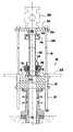
- FIG. 1is a side elevational view, partially in cross-section, of a spool for pressure containment in accordance with an embodiment of the invention
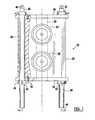
- FIG. 2is a top plan view of the spool shown in FIG. 1;
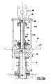
- FIG. 3is a side elevational view, partially in cross-section of a spool for pressure containment in accordance with another embodiment of the invention.
- FIGS. 4 a through 4 dillustrate alternative arrangements of securing prime movers to the spool shown in FIG. 1, or the spool shown in FIG. 2, in which FIGS. 4 a and 4 b are respectively partial side elevational and partial top plan views of a prime mover with its securing mechanism incorporated into spools, and FIGS. 4 c and 4 d are, respectively, a top plan and a cross-sectional view of a clamp used for securing the prime mover;
- FIG. 4 eis a partial cross-sectional view of the prime mover, showing an alternative configuration thereof;
- FIG. 5is a block diagram illustrating hydraulic circuits for supplying pressurized hydraulic fluid to hydraulic cylinders, when the hydraulic cylinders are used as prime movers;
- FIG. 6is a partial cross-sectional view of FIG. 1 or FIG. 2, according to a further embodiment of the present invention, showing a Bowen union mounted to a top of the spools and protected by a protective bonnet;
- FIG. 7is a top plan view of the protective bonnet shown in FIG. 6;
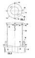
- FIG. 8is a partial side elevational view of the spool shown in FIG. 1 or the spool shown in FIG. 2, further including a hydraulic crane mounted thereon in accordance with a further embodiment of the invention;
- FIG. 9is a side view of the hydraulic crane shown in FIG. 8;
- FIG. 10 ais a cross-sectional view of a wellhead equipped with a spool in accordance with one embodiment of the invention, illustrating the insertion of a mandrel of a blowout preventer protector with a sealing assembly for pack-off in a casing of a well to be stimulated during a well workover procedure;
- FIG. 10 bis a top plan view of a work platform used with the spool shown in FIG. 10 a;
- FIG. 10 cis a cross-sectional view of the work platform shown in FIG. 10 b;
- FIG. 10 dis a partial cross-sectional view of an annular adapter for use with the Bowen union shown in FIG. 10 a , illustrating the details thereof;
- FIG. 11is a cross-sectional view of a wellhead equipped with an embodiment of the invention, for inserting a mandrel of a blowout preventer protector having an annular sealing body for sealing engagement with a bit guide that protects a top of a casing of the well, while supporting a tubing string in the well bore;
- FIG. 12is a cross-sectional view of a wellhead equipped with an embodiment of the invention, for inserting a tubing hanger with the tubing string into a tubing head spool in a live well;
- FIG. 13is a cross-sectional view of a wellhead equipped with an embodiment of the invention for running a coil tubing string into and out of the well after a blowout preventer protector is inserted through the wellhead;
- FIGS. 14 a and 14 bare partial cross-sectional views of configurations in accordance with the invention for connecting a prime mover to a base plate used to set tools on a live well.
- the inventionprovides an apparatus and methods for completing, re-completing or performing a workover on a well bore without using a service rig.
- the apparatus and methodscan be used in completing any well in which coil tubing is to be used for production.
- the method and apparatuscan also be used for re-working substantially any well in which tubing is already installed.
- the apparatusis also useful during well re-completion or servicing procedures, and permits tool insertion and other operations to be performed without the expense of a service rig.
- FIG. 1shows an apparatus, partially in a cross-sectional view in accordance with one embodiment of the present invention, generally indicated by reference numeral 20 .
- the apparatus 20includes a spool for pressure containment 22 having at least one flow control mechanism 24 , 26 .
- the spool for pressure containmentis a blowout preventer (BOP) 22 having opposed tubing rams 24 used to close an annulus of the well bore (not shown) around a production tubing (not shown) of a known diameter, and a set of opposed blind rams 26 , which are used to completely seal the well bore.
- BOPblowout preventer
- the construction of the tubing rams and blind rams of a BOPis well known in the art and will not be further described.
- a pair of bi-directional prime movers 28are secured to the BOP 22 at opposed sides thereof.
- the prime movers 28may be screw jacks, ball jacks or, as illustrated in FIG. 1, hydraulic cylinders.
- the prime movers 28are substantially vertically oriented and are received or secured by mechanisms integrated with the BOP 22 .
- the BOP 22includes a pair of bores 30 that are oriented in a substantially parallel relationship to a central bore 32 of the BOP 22 .
- the prime movers 28are received in the respective bores 30 and extend therethrough.
- each prime mover 28is longer than the bore 30 so that a lower end of the prime mover 28 projects downwardly from a bottom 34 of the BOP 22 when the top end of the prime mover 28 is secured to a top 36 of the BOP 22 .
- the prime movers 28can also be arranged to extend above, rather than below, the BOP 22 .
- a cylinder cap 37 having a larger diameter than the prime mover 28serves as a stop to restrain downward movement of the prime mover 28 relative to the BOP 22 .
- a lock ring 38 secured to the prime mover 28 by set screws 40restrains the prime mover 28 from upward movement relative to the BOP 22 .
- the set screws 40engage an annular groove 42 formed around the prime mover 28 just below the bottom 34 of the BOP 22 .
- Hydraulic connectors 44are provided at opposite ends of the prime mover 28 to permit hydraulic fluid to be injected into or withdrawn from either end of the prime mover 28 , in order to achieve a double acting functionality.
- the piston ram 46 of each prime mover 28is provided with a bore 48 at its top end for connecting a workload or an extension rod, as will be further described below.
- the BOP 22is provided with a plurality of threaded bores 50 in the bottom flange 34 and top flange 36 to permit the BOP 22 to be secured to other spools of a wellhead.
- FIG. 2shows a top plan view of the BOP 22 shown in FIG. 1, without the prime movers 28 .
- Four cylindrical bores 52are machined into the top 36 of the BOP 22 , adjacent to a periphery thereof.
- the bores 52receive and support support beams for a hydraulic crane, which will be further described with reference to FIGS. 8 and 9.
- Set screws 54are used to lock the support beams in the bores 52 .
- FIG. 3shows an apparatus 20 ′ in accordance with another embodiment of the invention.
- the spool for pressure containment 20 ′is a high pressure valve 22 ′ having at least one flow control mechanism 24 ′, which is a high pressure valve used for containment of pressurized fluid within a well bore, and is well known in the art.
- high pressure valve 22 ′includes a pair of parallel bores.
- the bores in this examplesupport prime movers that are screw or ball jacks 27 , which include a power transfer case 39 having a drive shaft 41 with a connector end 43 adapted to be connected to a hydraulic motor (not shown), or some other drive power source.
- the power transfer casetranslates rotational movement of the drive shaft 41 into vertical movement of a threaded shaft 45 , in a manner well known in the art.
- the top end of the threaded shaft 45includes a bore 47 for connection of an extension or other tool, as will be explained below in more detail.
- Other structural features of the apparatus 20 ′are similar to those described with reference to the apparatus 20 shown in FIG. 1 .
- the top 36 of the high pressure valve 22 ′has a layout similar to that of the BOP 22 described above with reference to FIG. 2 .
- FIGS. 4 a and 4 bshow an alternative configuration for securing the prime movers' hydraulic cylinders 28 or jacks 27 to the BOP 22 .
- the BOP 22instead of the bores 30 through the BOP 22 shown in FIG. 1, the BOP 22 , partially shown in FIGS. 4 a and 4 b , includes a pair of brackets 56 at opposite sides of the top 36 thereof and a pair of brackets 58 at the opposite sides of the bottom 34 .
- the pair of brackets 56are spaced apart slightly more than an external diameter of the prime movers 27 , 28 and a groove 60 is formed in a top flange 62 of the BOP 22 .
- brackets 58are spaced apart slightly more than the external diameter of the prime mover 27 , 28 and a groove 64 is formed in a bottom flange 66 between the brackets 58 .
- one of the prime movers 27 , 28is received in the respective grooves 60 , 64 and between the brackets 56 , 58 , and is locked in position by bolts 68 .
- FIGS. 4 c and 4 cshow an alternative to the lock ring 38 , which can be replaced with a clamp 70 .
- the clamp 70is made in two parts that form a hollow cylinder with a radially inwardly projecting annular shoulder 72 and radially outwardly protruding ears 74 which can be secured together by lock screws 76 .
- the two parts of the clamp 70are placed around the prime mover 27 , 28 , similarly to the lock ring 38 shown in FIG. 1, while inserting the radially inwardly projecting annular shoulder 72 of the clamp 70 into the annular groove 42 of the prime mover 28 .
- the two halves of the clamp 70are then secured together by lock screws 76 , which are inserted through bores in the lock ears 74 .
- the prime mover 28is secured to the BOP 22 by a bottom end cap 78 , as shown in FIG. 4 e .
- the bottom end cap 78includes an extended side wall 80 that extends upwardly over the lower section of the prime mover 28 , so that the bottom end cap 78 inhibits the prime mover 28 from upward movement relative to the BOP 22 .
- the locking arrangement illustrated in FIGS. 4 c , 4 d and 4 emay be used in conjunction with either bores 30 shown in FIG. 1 or brackets 56 , 58 shown in FIGS. 4 a and 4 b .
- the locking mechanisms illustrated in FIGS. 4 a through 4 emay be used to secure prime movers to BOP 22 or the high pressure valve 22 ′.
- FIG. 5illustrates a hydraulic circuit for supplying pressurized fluid to actuate the prime movers 28 .
- the hydraulic circuitgenerally indicated by reference numeral 82 , includes a motor 84 coupled to a pump 86 .
- the pump 86pumps hydraulic fluid from a reservoir (not shown) into an accumulator 88 , which generally includes a bladder to ensure that the hydraulic pressure is maintained in the hydraulic circuit 82 in case the pump 86 or motor 84 fail.
- the pressurized hydraulic fluid from the accumulator 88is distributed by two valves 90 , so that the prime movers 28 can be controllably actuated to extend or retract. When hydraulic fluid is introduced into one end of the prime movers 28 the exhausted hydraulic fluid drains from the other end of the prime movers 28 into the reservoir (not shown).
- FIG. 6illustrates the apparatus 20 shown in FIG. 1 further including a threaded connector 92 , commonly called a Bowen connector.
- the threaded connector 92includes a base flange 94 and a cylindrical fitting 96 , with a central bore 98 that extends therethrough.
- the central bore 98has a diameter substantially the same size as the central bore 32 of the BOP 22 .
- a landing bore 100has a larger diameter than the central bore 98 .
- External threads 102are provided at the top of the fitting 96 .
- the treaded connector 92is mounted to the top 36 of the BOP 22 by a plurality bolts 104 , which extend through bores in the base flange 94 and are received in the threaded bores 50 in the top 36 of the BOP 22 .
- a protective bonnet 106is selectively placed over the threaded connector 92 .
- the bonnet 106includes a cylindrical side wall 108 and a top wall 110 with a central bore 112 therethrough.
- the bonnet 106is assembled from two parts 114 and 116 , which are pivotally connected together on one side by a hinge pin 118 to permit the bonnet 106 to be opened and closed.
- a locking device 120is provided on the opposite sides of the two parts 114 , 116 to lock the two parts 114 , 116 together.
- a pair of lifting ears 122 with bores 125 therethroughare provided on the respective parts 114 , 116 to permit the bonnet 106 to be lifted as required.
- FIG. 8illustrates the apparatus 20 shown in FIG. 1, further including a hydraulic crane 124 which is removably mounted to the top 36 of the BOP 22 .
- the hydraulic crane 124is supported by four support beams 126 , a top end of each being inserted into a corresponding socket 128 of the hydraulic crane 124 and locked by set screws 130 .
- the bottom end of each support beam 126is received in one of the bores 52 (see FIG. 2) in the top 36 of the BOP 22 and secured by the set screws 54 , as described above.
- the hydraulic crane 124includes a base 132 which can be a plate, a cylindrical box structure, a beam, or the like.
- a bracket member 134is rotatably coupled to the base 132 .
- the bracket member 134includes a downwardly extending arm 136 .
- a lower end of the arm 136is connected to a telescoping boom 138 by a pivot pin 140 .
- a hydraulic cylinder 142interconnects a base section 144 of the telescoping boom 138 and the bracket member 134 , so that the telescoping boom 138 can be pivoted by the hydraulic cylinder 142 about the pivot pin 140 from a substantially horizontal position to a substantially vertical position, as shown by the arrow 146 .
- An extension 148 of the telescoping boom 138can be extended or retracted by another hydraulic cylinder, or as shown in FIG. 9, by pressurized hydraulic fluid introduced into an inner chamber of the base section 144 , which exerts hydraulic pressure on the piston 150 of the extension 148 .
- a cable 152is wound around a drum 154 which is rotatably mounted to the arm 136 and is driven by a hydraulic motor (not shown).
- the cable 152extends along the length of the telescoping boom 138 and around a pulley 156 which is rotatably mounted to a free end of the extension section 148 , and is connected at its free end to a lifting hook 158 , for example.
- the bracket member 134 with the telescoping boom 138is rotatable about a vertical axis relative to the base 132 in a range of about 360° when the telescoping boom 138 is in a retracted or a downwardly pivoted position.
- a hydraulic motor 159is preferably provided on the top of the base 132 to rotate the bracket member 134 .
- the prime movers 28 shown in FIG. 1are used to support a heavy workload, such as the weight of an entire tubing string suspended in a well bore, or the high fluid pressure acting on tools to be inserted into the well bore.
- the hydraulic craneis used for different purposes and can be used in an area surrounding the wellhead, but can only support a limited workload.
- the hydraulic crane 124 in accordance with this embodimenthas a limited lifting capacity of about three tons.
- the apparatus 20is enabled to provide all of the services required for a rigless well completion, re-completion, servicing or workover. A few examples of applications using the apparatus 20 in well completion, re-completion, servicing or workover are described below.
- FIG. 10 aillustrates an example of using the apparatus 20 to insert a mandrel 160 of a BOP protector into a wellhead 162 .
- the mandrel 160has a seal assembly 164 mounted to its bottom end for pack-off inside a casing 166 of the well to be stimulated.
- Mounted to the top of the wellhead 162is the BOP 22 with the two prime movers 27 , 28 .
- the installation of the BOP 22is accomplished by a boom truck (not illustrated) for example, used to hoist the BOP 22 from a transportation deck (not shown).
- the deckpreferably includes bores for receiving the two prime movers 27 , 28 that project downwardly from the BOP 22 , so that they do not have to be removed from the BOP 22 for transportation.
- the hydraulic crane 124as shown in FIG. 8 is then mounted to the top of the BOP 22 .
- the hydraulic crane 124is not shown in FIG. 10 a .
- the boom truckis no longer required. If the boom truck is kept on site, the hydraulic crane 124 is not required.
- the threaded connector 92is hoisted by the hydraulic crane 124 (see FIG. 8 ), for example, to the top of the BOP 22 and is secured thereto if the threaded connector 92 has not been previously connected to the BOP 22 .
- the mandrel 160 with its sealing assembly 164is equipped with an annular adapter 168 .
- the annular adapter 168more clearly shown in FIG. 10 d includes a cylindrical side wall 170 and a bottom wall 172 with a central bore 174 , which has the same diameter as the central bore 98 of the threaded connector 92 (see FIG. 6 ).
- An external shoulder 176protrudes from the cylindrical side wall 170 .
- Packing rings 178constructed of brass, rubber and fabric are disposed within the cylindrical side wall 170 and are secured between the bottom wall 172 and a gland nut 180 , which has external threads 182 that engage corresponding internal threads 184 in the cylindrical side wall 170 .
- the packing rings 178 and the gland nut 180define a vertical passage 186 of a same diameter as a periphery of the mandrel 160 , to provide a fluid seal between the mandrel 160 and the annular adapter 168 , as shown in FIG. 10 a .
- the annular adapter 168further includes two high-pressure O-rings 188 engaged in grooves around the periphery of the cylindrical side wall 170 below the external shoulder 176 .
- the O-rings 188provide a fluid tight seal between the annular adapter 168 and the threaded connector 92 when the annular adapter 168 is seated within the threaded connector 92 , as shown in FIG. 10 a .
- a lock nut 190engages the external shoulder 176 and includes internal threads that are threadedly engaged with the threaded connector 92 when the annular adapter 168 is seated within the threaded connector 92 .
- the mandrel 160which is surrounded by the annular adapter 168 is connected at its top end to a connector 192 that includes a base plate 194 .
- the connection of the top end of the mandrel 160 to the connector 192is described in detail in Applicant's issued patents.
- the connector 192further includes a lock nut 196 for engagement with the external threads 198 of the annular adapter 168 (see FIG. 10 d ).
- the combination of the mandrel 160 with the base plate 194 and the annular adapter 168is hoisted by the hydraulic crane 124 (see FIG. 8) and is positioned above the top 36 of the BOP 22 .
- the combinationis lowered by the hydraulic crane 124 , or a crane truck (not shown), until the seal assembly 164 of the mandrel 160 is inserted into the central bore of the threaded connector 92 , or further down into the central bore of the BOP 22 above the blind rams 26 (see FIG. 1 ), which are closed.
- the annular adapter 168can be suspended on the mandrel 160 by a frictional force between the packing rings 178 and the periphery of the mandrel 160 , or can be suspended from the lock nut 196 .
- the annular adapter 168is pushed down and seated within the threaded connector 92 , and is locked down using the lock nut 190 .
- FIG. 10 aspecifically illustrates this stage.
- a pair of extension rods 204which are inserted through bores 206 of the base plate 194 , are connected to the extended piston rams 46 of the prime movers 28 .
- a high pressure valve 200is then connected to a top of the base plate 194 , in order to controllably close the fluid passage defined by the central bore 202 of the base plate 194 .
- the mandrel 160is ready to be inserted into the wellhead 162 against well fluid pressure.
- the blind rams 26 of the BOP 22(see FIG. 1) are opened and the mandrel 160 is subjected to the well fluid pressure.
- the pressureis preferably balanced between the mandrel 160 and the well bore before the blind rams are opened, using methods well known in the art.
- An upward force exerted by the well fluid pressure on the mandrel 160is transferred by means of the base plate 194 and the extension rods 104 , to the piston rams 46 of the prime movers 27 28 , which are hydraulically locked.
- the prime movers 27 , 28are then actuated to lower the base plate 194 and thereby insert the mandrel 160 through the packing rings 178 of the annular adapter 168 and into the wellhead 162 until the seal assembly 164 of the mandrel 160 is packed off within the casing 166 .
- the lock nut 196 of the connector 192is then threadedly engaged with the annular adapter 168 .
- a work platform 208(more clearly shown in FIGS. 10 b and 10 c ) is optionally provided so that operators have a place to stand for working over the wellhead 162 .
- the work platform 208has a central aperture 209 and a plurality of openings 211 and 213 .
- the work platform 208is substantially horizontally disposed at a level not lower than the top 36 of the BOP 22 (see FIG. 10 a ), and is preferably placed on the top 36 of the BOP 22 , while being supported by legs 215 which rest on the ground.
- the legs 215include height adjustment mechanisms that include pressure feet 207 rotatably connected to threaded extension legs 205 .
- the central opening 209receives the threaded connector 92 and the openings 211 , 213 permit the respective piston rams 46 of the prime movers 27 , 28 and the supporting beams 126 of the hydraulic crane 124 (see FIG. 8) to pass therethrough.
- FIG. 11Another example of using the apparatus 20 in a rigless well completion, re-completion, servicing or workover is illustrated in FIG. 11.
- the tubing stringis supported by, for example, slips 218 or some other support mechanism, at the top of the wellhead 214 .
- the BOP 22 of the present inventionis mounted to a tubing head spool 220 .
- the tubing string 216is normally supported by a tubing hanger inside the tubing head spool 220 , but the tubing hanger has been pulled out of the well using the prime movers 27 , 28 , for example, to an extent that a length of the tubing string 216 that extends above the wellhead 214 is greater than a length of the BOP 22 .
- the tubing string 216is then supported on the top of the protective bonnet 106 using slips 218 , for example, before the mandrel insertion procedure begins.
- the process of using prime movers 27 , 28 to install a tubing hanger (not shown) in the tubing head spool 220 or to remove the tubing hanger from samewill be further described with reference to FIG. 12 .
- a fracturing head 222 having a central passage 224 and at least two radial passages 226 , 228is mounted to the top of the base plate 194 , before the combination of the mandrel 210 , the base plate 194 and the annular adapter 168 is hoisted above the wellhead 214 .
- Two high pressure valves 230 , 232are also mounted to the fracturing head 222 to close the radial passages 226 , 228 , respectively.
- the mandrel 210is aligned with the tubing string 216 and is lowered over the tubing string 216 until the top end 234 of the tubing string 216 extends above the top end of the fracturing head 222 .
- a tubing adapter 236is then connected to the top end 234 of the tubing string 216 .
- the tubing adapter 236is also connected to the top of the fracturing head 222 .
- the extension rods 204are then connected to the piston ram 46 of the prime movers 27 , 28 which are in the extended position, and to the base plate 194 .
- the hydraulic crane 124can be used to hoist a high pressure valve 200 (partially shown) to the top of the tubing adapter 236 .
- the high pressure valve 200is then mounted to the top of the tubing adapter 236 .
- the tubing string 216 and the mandrel 210are supported by the prime movers 27 , 28 so that the slips 218 and the cylindrical protector 106 can be removed in order to clear the passage for insertion of the mandrel 210 .
- the prime movers 27 , 28are actuated to lower the tubing string 216 and the mandrel 210 onto the top of the BOP 22 so that the annular adapter 168 can be pushed down over the mandrel 210 and connected to the threaded connector 92 , similarly to the position illustrated in FIG. 10 a .
- the mandrel 210is inserted into the threaded connector 92 and the BOP 22 , but remains above the BOP tubing rams 24 (FIG. 1 ).
- the high pressure valves 230 , 232 and 200must be closed and the annular adapter 168 must be sealingly connected to the threaded connector 92 .
- the packing rings 178 and all other seals between interfaces of the connected partsseal the central passage of the mandrel 210 against pressure leaks.
- the tubing rams 24 of the BOP 22are opened after pressure is balanced across the BOP tubing rams 24 . This procedure is well known in the art. After the BOP tubing rams 24 are opened, the prime movers 27 , 28 are operated to lower the mandrel 210 down through the BOP 22 .
- the bottom end of the pack-off assembly 212is in sealing contact with a bit guide 246 connected to a top of the casing 166 .
- the bit guide 246caps the casing 166 to protect the top end of the casing 166 and provides a seal between the casing 166 and the tubing head spool 220 , in a manner well known in the art.
- the mandrel 210has optional and variable lengths of extension sections.
- the assembled mandrel 210 including the pack-off assembly 212is pre-adjusted in length to ensure that the lock nut 196 is able to be threadedly engaged with the annular adapter 168 when the pack-off assembly 212 is seated against the bit guide 246 .
- the prime movers 27 , 28are preferably hydraulically locked during the well stimulation procedure that follows, in order to support the weight of the tubing string 216 , including the equipment and tools attached thereto.
- FIG. 12illustrates a procedure for using an apparatus 20 ′′, in accordance with a further embodiment of the invention, to install a tubing hanger 248 into the tubing head spool 220 or remove it from the tubing head spool 202 .
- the tubing hanger 248must be set in the tubing head spool 220 in order to suspend the production tubing string 216 in the well after the production tubing string 216 has been run into the well.
- the tubing hanger 248is connected to a top end of the tubing string 216 , and conventionally, special equipment is required to run the tubing hanger 248 into the tubing spool 220 .
- the tubing hanger 248must be removed from the tubing head spool when a mandrel 210 of a BOP protector is to be inserted into the wellhead 214 , as illustrated in FIG. 11 .
- the apparatus 20 ′′permits the tubing hanger 248 to be rapidly and safely inserted into or removed from the tubing head spool 220 of a “live” well without use of an additional BOP.
- the apparatus 20 ′′is similar to the apparatus 20 and 20 ′ illustrated in FIGS. 10 a and 11 , and similar parts are indicated by the same reference numerals and are not described.
- an annular adapter 250described in Applicant's copending U.S. patent application Ser. No. 09/791,980 filed Feb. 23, 2001, the specification of which is incorporated herein by reference, replaces the annular adapter 168 of the apparatus 20 described above.
- a landing joint 252which is rotatably suspended from and supported by a base plate 194 and is adapted to be connected to the tubing hanger 248 , replaces the connector 192 of the apparatus 20 , which connects the annular adapter 168 to the base plate 194 as illustrated in FIG. 10 a .
- the landing joint 252is inserted through a passage 254 of the annular adapter 250 .
- the passage 254includes a packing cavity at a top thereof, which retains a steel packing washer 256 .
- a high pressure packing 258such as a chevron packing, is retained above the steel packing washer 256 .
- the high pressure packing 258closely surrounds and provides a high pressure seal around the landing joint 252 to ensure that well fluids do not escape to the atmosphere when the tubing hanger 248 is inserted into, or removed from, the tubing head spool 220 .
- the high pressure packing 258is retained by a gland nut 260 .
- a safety nut 262threadedly engages a spiral thread on an outer periphery of the top end of the annular adapter 250 .
- a top wall of the safety nut 262projects inwardly to cover the gland nut 262 in order to ensure that the gland nut 262 is not stripped by fluid pressures exerted on the high pressure packing 258 .
- a side wall of the annular adapter 250includes at least two eyes or hooks 264 which receive chain or cable 266 that is connected to the hydraulic crane 124 (see FIG. 8) in order to suspend the annular adapter 250 , while the landing joint 252 is connected to a top end of the tubing hanger 248 .
- the annular adapter 250is also suspended while slips 218 (see FIG. 11) that suspend the production tubing string 216 are removed to permit the tubing hanger 248 to be inserted down through the BOP 22 .
- the extension rods 204are connected to the piston rams 46 of the prime movers 28 , which are in their extended condition and are hydraulically locked.
- the slips 218are then removed and the weight of the production tubing string 216 is therefore transferred to the prime movers 28 .
- the landing joint 252is lowered to move the tubing hanger 248 down into the threaded connector 92 and the BOP 22 , but support it above the closed tubing rams 24 of the BOP 22 .
- a retrievable plug 268which seals a bottom of the production tubing string 216 , seals the well fluids within the well.
- the annular adapter 250which is suspended from the cables 266 by the hydraulic crane 124 (see FIG. 8 ), is lowered so that the lock nut 190 of the annular adapter 250 can be threadedly engaged with the threaded connector 92 .
- the O-rings 188 around the annular adapter 250seal the interface between the annular adapter 250 and the threaded connector 92 .
- the landing joint 252is then rotated, preferably by a hydraulic motor 276 , to disconnect the landing joint 252 from the tubing hanger 248 , and the landing joint 252 is raised with the base plate 194 by operating the prime movers 28 until the landing joint 252 is above the blind rams 26 (FIG. 1) of the BOP 22 .
- pressureis vented from the annular adapter 250 by, for example, opening the pressure bleed ports 270 .
- the annular adapter 250is removed by the hydraulic crane 124 (see FIG. 8 ).
- FIG. 13illustrates a method of installing the mandrel 160 of a BOP protector to permit the tubing string 216 to be run into or out of the well while protecting the BOP 22 on the wellhead during a well stimulation treatment.
- the mandrel 160 with the annular adapter 168 and the fracturing head 222are assembled to the base plate 194 , and a second BOP 278 is mounted to a top of a tubing adapter 280 .
- a blast joint 282is threadedly engaged with the tubing adapter 280 so that the blast joint 282 is suspended from the tubing adapter 280 .
- the blast joint 282has an inner diameter large enough to permit the coil tubing string 216 to be run in and out therethrough.
- the blast joint 282protects the coil tubing string 216 from erosion when abrasive fluids are pumped through the radial passage 226 , 228 in the fracturing head 222 , after the coil tubing string 216 is run into the well and a well stimulation treatment is begun.
- the combination of the mandrel 160 , the annular adapter 168 , the base plate 194 , the fracturing head 222 , which also includes the high pressure valves 230 , 232 , and the second BOP 278is assembled, the combination is hoisted by the hydraulic crane (see FIG. 8 ), to a position over the wellhead 214 .
- the second BOP 278may be mounted to the fracturing head 222 after it is connected to the extension rods 204 .
- the procedurethen follows the steps described with reference to FIG. 10 a until the mandrel 160 is inserted into the wellhead 214 in the operative position as shown in FIG. 13, and is locked into position by the lock nuts 190 , 196 .
- a coil tubing injector 284is hoisted by a boom truck (not shown) or the hydraulic crane 124 (see FIG. 8) above the second BOP 278 , and is mounted to a top of the BOP 278 .
- the coil tubing string 216can then be run into, and out of, the well without removing the apparatus 20 from the wellhead 214 .
- the tubing string 126can also be moved up or down in the well while stimulation fluids are being pumped into the well.
- the connection of the extension rods 204 to the base plate 194is more clearly illustrated in FIGS. 14 a and 14 b .
- the extension rod 204includes a hex head 238 , which may include a threaded bore 240 in a top thereof.
- a connector 242is provided at a lower end of the extension rod 204 for connection to the piston ram 46 (see FIG. 1) of a prime mover 27 , 28 , or to another extension rod.
- the extension rod 204is connected to the base plate 194 by an extension rod connector 244 , as shown in FIG. 14 b and FIG. 11, so that the prime movers 28 can resist both upward and downward forces.
- the apparatus of the present inventioncan be used in various other operations required for well completion, re-completion, servicing or workover without requiring a service rig. Under normal conditions, the service rig can be released as soon as drilling is complete, which represents a considerable savings for well owners and operators.
Landscapes
- Life Sciences & Earth Sciences (AREA)
- Engineering & Computer Science (AREA)
- Geology (AREA)
- Mining & Mineral Resources (AREA)
- Physics & Mathematics (AREA)
- Environmental & Geological Engineering (AREA)
- Fluid Mechanics (AREA)
- General Life Sciences & Earth Sciences (AREA)
- Geochemistry & Mineralogy (AREA)
- Earth Drilling (AREA)
Abstract
Description
Claims (21)
Priority Applications (2)
| Application Number | Priority Date | Filing Date | Title |
|---|---|---|---|
| US09/998,953US6712147B2 (en) | 2001-11-15 | 2001-11-15 | Spool for pressure containment used in rigless well completion, re-completion, servicing or workover |
| CA002363710ACA2363710C (en) | 2001-11-15 | 2001-11-23 | Spool for pressure containment used in rigless well completion, re-completion, servicing or workover |
Applications Claiming Priority (2)
| Application Number | Priority Date | Filing Date | Title |
|---|---|---|---|
| US09/998,953US6712147B2 (en) | 2001-11-15 | 2001-11-15 | Spool for pressure containment used in rigless well completion, re-completion, servicing or workover |
| CA002363710ACA2363710C (en) | 2001-11-15 | 2001-11-23 | Spool for pressure containment used in rigless well completion, re-completion, servicing or workover |
Publications (2)
| Publication Number | Publication Date |
|---|---|
| US20030089502A1 US20030089502A1 (en) | 2003-05-15 |
| US6712147B2true US6712147B2 (en) | 2004-03-30 |
Family
ID=32070508
Family Applications (1)
| Application Number | Title | Priority Date | Filing Date |
|---|---|---|---|
| US09/998,953Expired - LifetimeUS6712147B2 (en) | 2001-11-15 | 2001-11-15 | Spool for pressure containment used in rigless well completion, re-completion, servicing or workover |
Country Status (2)
| Country | Link |
|---|---|
| US (1) | US6712147B2 (en) |
| CA (1) | CA2363710C (en) |
Cited By (37)
| Publication number | Priority date | Publication date | Assignee | Title |
|---|---|---|---|---|
| US20030221823A1 (en)* | 2002-02-19 | 2003-12-04 | Duhn Rex E. | Wellhead isolation tool |
| US20040173347A1 (en)* | 2003-03-07 | 2004-09-09 | Dallas L. Murray | Apparatus for controlling a tool having a mandrel that must be strocked into or out of a well |
| US20050082066A1 (en)* | 2003-10-21 | 2005-04-21 | Mcguire Bob | Hybrid wellhead system and method of use |
| US20050092496A1 (en)* | 2002-02-19 | 2005-05-05 | Duhn Rex E. | Wellhead isolation tool and method of fracturing a well |
| US20050199389A1 (en)* | 2004-03-12 | 2005-09-15 | Dallas L. M. | Wellhead and control stack pressure test plug tool |
| US20050217868A1 (en)* | 2004-03-31 | 2005-10-06 | Dallas L M | Casing-engaging well tree isolation tool and method of use |
| US6976670B1 (en)* | 2004-12-23 | 2005-12-20 | Brent Alan Woolley | Hydraulic puller apparatus |
| US20060060349A1 (en)* | 2002-02-19 | 2006-03-23 | Duhn Rex E | Wellhead isolation tool and method of fracturing a well |
| US20060137882A1 (en)* | 2004-12-28 | 2006-06-29 | Mcguire Bob | Blast joint swivel for wellhead isolation tool and method of using same |
| US20060185841A1 (en)* | 2005-02-18 | 2006-08-24 | Fmc Technologies, Inc. | Fracturing isolation sleeve |
| US20070012486A1 (en)* | 2005-07-15 | 2007-01-18 | Mcguire Bob | Slip spool assembly and method of using same |
| US20070079990A1 (en)* | 2005-10-06 | 2007-04-12 | Vetco Gray Inc. | System, method, and apparatus for accessing outlets in a two-stage diverter spool assembly |
| US20070107910A1 (en)* | 2004-03-17 | 2007-05-17 | Mcguire Bob | Hybrid wellhead system and method of use |
| US20070227742A1 (en)* | 2006-04-04 | 2007-10-04 | Oil States Energy Services, Inc. | Casing transition nipple and method of casing a well to facilitate well completion, re-completion and workover |
| US20070227743A1 (en)* | 2006-04-04 | 2007-10-04 | Oil States Energy Services, Inc. | Method of subsurface lubrication to facilitate well completion, re-completion and workover |
| US20080017371A1 (en)* | 2006-07-19 | 2008-01-24 | 1128971 Alberta Ltd. | Method and apparatus for restraining tubular members during well servicing |
| US20080078558A1 (en)* | 2006-09-28 | 2008-04-03 | Oil States Energy Services, Inc. | Subsurface lubricator and method of use |
| US20080078557A1 (en)* | 2006-09-28 | 2008-04-03 | Oil States Energy Services, Inc. | Subsurface lubricator and method of use |
| US20080083539A1 (en)* | 2006-10-06 | 2008-04-10 | Stinger Wellhead Protection, Inc. | Retrievable frac mandrel and well control stack to facilitate well completion, re-completion or workover and method of use |
| US20080142210A1 (en)* | 2003-09-04 | 2008-06-19 | Stinger Wellhead Protection, Inc. | Drilling Flange and Independent Screwed Wellhead With Metal-to-Metal Seal and Method of Use |
| US20080257540A1 (en)* | 2007-04-17 | 2008-10-23 | Stinger Wellhead Protection, Inc. | Multipart frac head with replaceable components |
| US20090145593A1 (en)* | 2007-12-05 | 2009-06-11 | Stinger Wellhead Protection, Inc. | Snubber Spool With Detachable Base Plates |
| US20090159273A1 (en)* | 2007-12-21 | 2009-06-25 | Schlumberger Technology Corporation | Logging tool deployment systems and methods with pressure compensation |
| US20090236090A1 (en)* | 2008-03-20 | 2009-09-24 | Stinger Wellhead Protection, Inc. | Erosion Resistant Frac Head |
| US20110036589A1 (en)* | 2009-08-17 | 2011-02-17 | Stream-Flo Industries Ltd. | Wellhead connection |
| US20110048736A1 (en)* | 2009-09-03 | 2011-03-03 | Hydril Usa Manufacturing Llc | Crane Device and Method |
| US20110155394A1 (en)* | 2009-12-29 | 2011-06-30 | Hydril Usa Manufacturing Llc | Lifting Device and Method for Lifting a Bonnet |
| US20120298372A1 (en)* | 2010-01-25 | 2012-11-29 | Geoprober Drilling Limited | Apparatus and method for abandoning a well |
| US8485262B1 (en)* | 2008-09-26 | 2013-07-16 | John W. Angers | Modular, stackable wellhead system |
| US8820400B2 (en) | 2008-03-20 | 2014-09-02 | Oil States Energy Services, L.L.C. | Erosion resistant frac head |
| US8931551B2 (en) | 2007-04-17 | 2015-01-13 | Oil States Energy Services, L.L.C. | Multipart frac head with replaceable components |
| US9404341B2 (en) | 2013-09-10 | 2016-08-02 | Dwj Inc. | Release tool for a drill string inside blowout preventer |
| US9404321B2 (en) | 2014-04-23 | 2016-08-02 | Dwj Inc. | Oilfield lift cap and combination tools |
| US9771766B2 (en) | 2015-03-03 | 2017-09-26 | Dwj Inc. | Release tool with adjustable release rod for a drill string inside blowout preventer |
| US20180030791A1 (en)* | 2016-07-28 | 2018-02-01 | Cameron International Corporation | Lifting Apparatus for Subsea Equipment |
| US10113380B2 (en)* | 2014-08-19 | 2018-10-30 | Schlumberger Technology Corporation | Pumping system deployment using cable |
| US11542773B2 (en) | 2013-10-03 | 2023-01-03 | Don Atencio | Variable high pressure transition tube set point adapter |
Families Citing this family (5)
| Publication number | Priority date | Publication date | Assignee | Title |
|---|---|---|---|---|
| CA2364151A1 (en)* | 2001-11-28 | 2003-05-28 | L. Murray Dallas | Well stimulation and method of use |
| GB0408753D0 (en)* | 2004-04-20 | 2004-05-26 | Quip Ltd P | Sealing device |
| US10577894B1 (en) | 2015-06-08 | 2020-03-03 | DataInfoCom USA, Inc. | Systems and methods for analyzing resource production |
| US10866962B2 (en) | 2017-09-28 | 2020-12-15 | DatalnfoCom USA, Inc. | Database management system for merging data into a database |
| CN118390980A (en)* | 2024-06-26 | 2024-07-26 | 河北新铁虎石油机械有限公司 | Composite pipe column pipe lifting device with pressure |
Citations (20)
| Publication number | Priority date | Publication date | Assignee | Title |
|---|---|---|---|---|
| US3738426A (en)* | 1971-02-16 | 1973-06-12 | Rockwell Mfg Co | Subsidence wellhead assembly and method |
| US4076079A (en)* | 1976-08-16 | 1978-02-28 | Shell Oil Company | Full bore fracture treating assembly |
| US4125164A (en)* | 1977-08-24 | 1978-11-14 | Terry William A | Apparatus and method for lifting a bop from a wellhead |
| US4241786A (en) | 1978-05-02 | 1980-12-30 | Bullen Ronald S | Well tree saver |
| US4476936A (en)* | 1981-12-21 | 1984-10-16 | Varco International, Inc. | Jacking mechanism supported by a wellhead |
| US4632183A (en)* | 1984-01-09 | 1986-12-30 | Mcleod Roderick D | Insertion drive system for tree savers |
| US4867243A (en) | 1988-05-20 | 1989-09-19 | Garner Jonathan W | Wellhead isolation tool and setting and method of using same |
| US5540282A (en)* | 1994-10-21 | 1996-07-30 | Dallas; L. Murray | Apparatus and method for completing/recompleting production wells |
| US5785121A (en)* | 1996-06-12 | 1998-07-28 | Dallas; L. Murray | Blowout preventer protector and method of using same during oil and gas well stimulation |
| US5819851A (en)* | 1997-01-16 | 1998-10-13 | Dallas; L. Murray | Blowout preventer protector for use during high pressure oil/gas well stimulation |
| US5988274A (en) | 1997-07-30 | 1999-11-23 | Funk; Kelly | Method of and apparatus for inserting pipes and tools into wells |
| US6009941A (en) | 1997-12-17 | 2000-01-04 | Haynes; Michael Jonathon | Apparatus for axially displacing a downhole tool or a tubing string in a well bore |
| US6145596A (en) | 1999-03-16 | 2000-11-14 | Dallas; L. Murray | Method and apparatus for dual string well tree isolation |
| US6179053B1 (en)* | 1999-08-12 | 2001-01-30 | L. Murray Dallas | Lockdown mechanism for well tools requiring fixed-point packoff |
| US6209633B1 (en) | 1997-12-17 | 2001-04-03 | Michael Jonathon Haynes | Apparatus and method for axially displacing a downhole tool or a tubing string in a well bore |
| US6220363B1 (en) | 1999-07-16 | 2001-04-24 | L. Murray Dallas | Wellhead isolation tool and method of using same |
| US6234253B1 (en)* | 1998-11-30 | 2001-05-22 | L. Murray Dallas | Method and apparatus for well workover or servicing |
| US6289993B1 (en)* | 1999-06-21 | 2001-09-18 | L. Murray Dallas | Blowout preventer protector and setting tool |
| US6364024B1 (en)* | 2000-01-28 | 2002-04-02 | L. Murray Dallas | Blowout preventer protector and method of using same |
| US6470965B1 (en)* | 2000-08-28 | 2002-10-29 | Colin Winzer | Device for introducing a high pressure fluid into well head components |
- 2001
- 2001-11-15USUS09/998,953patent/US6712147B2/ennot_activeExpired - Lifetime
- 2001-11-23CACA002363710Apatent/CA2363710C/ennot_activeExpired - Lifetime
Patent Citations (20)
| Publication number | Priority date | Publication date | Assignee | Title |
|---|---|---|---|---|
| US3738426A (en)* | 1971-02-16 | 1973-06-12 | Rockwell Mfg Co | Subsidence wellhead assembly and method |
| US4076079A (en)* | 1976-08-16 | 1978-02-28 | Shell Oil Company | Full bore fracture treating assembly |
| US4125164A (en)* | 1977-08-24 | 1978-11-14 | Terry William A | Apparatus and method for lifting a bop from a wellhead |
| US4241786A (en) | 1978-05-02 | 1980-12-30 | Bullen Ronald S | Well tree saver |
| US4476936A (en)* | 1981-12-21 | 1984-10-16 | Varco International, Inc. | Jacking mechanism supported by a wellhead |
| US4632183A (en)* | 1984-01-09 | 1986-12-30 | Mcleod Roderick D | Insertion drive system for tree savers |
| US4867243A (en) | 1988-05-20 | 1989-09-19 | Garner Jonathan W | Wellhead isolation tool and setting and method of using same |
| US5540282A (en)* | 1994-10-21 | 1996-07-30 | Dallas; L. Murray | Apparatus and method for completing/recompleting production wells |
| US5785121A (en)* | 1996-06-12 | 1998-07-28 | Dallas; L. Murray | Blowout preventer protector and method of using same during oil and gas well stimulation |
| US5819851A (en)* | 1997-01-16 | 1998-10-13 | Dallas; L. Murray | Blowout preventer protector for use during high pressure oil/gas well stimulation |
| US5988274A (en) | 1997-07-30 | 1999-11-23 | Funk; Kelly | Method of and apparatus for inserting pipes and tools into wells |
| US6009941A (en) | 1997-12-17 | 2000-01-04 | Haynes; Michael Jonathon | Apparatus for axially displacing a downhole tool or a tubing string in a well bore |
| US6209633B1 (en) | 1997-12-17 | 2001-04-03 | Michael Jonathon Haynes | Apparatus and method for axially displacing a downhole tool or a tubing string in a well bore |
| US6234253B1 (en)* | 1998-11-30 | 2001-05-22 | L. Murray Dallas | Method and apparatus for well workover or servicing |
| US6145596A (en) | 1999-03-16 | 2000-11-14 | Dallas; L. Murray | Method and apparatus for dual string well tree isolation |
| US6289993B1 (en)* | 1999-06-21 | 2001-09-18 | L. Murray Dallas | Blowout preventer protector and setting tool |
| US6220363B1 (en) | 1999-07-16 | 2001-04-24 | L. Murray Dallas | Wellhead isolation tool and method of using same |
| US6179053B1 (en)* | 1999-08-12 | 2001-01-30 | L. Murray Dallas | Lockdown mechanism for well tools requiring fixed-point packoff |
| US6364024B1 (en)* | 2000-01-28 | 2002-04-02 | L. Murray Dallas | Blowout preventer protector and method of using same |
| US6470965B1 (en)* | 2000-08-28 | 2002-10-29 | Colin Winzer | Device for introducing a high pressure fluid into well head components |
Non-Patent Citations (2)
| Title |
|---|
| Patent application Ser. 09/537,629 entitled "Blowout Preventer Protector and Method of Using Same," filed Mar. 29, 2000. |
| Patent application Ser. 09/791,980 entitled "Method and Apparatus for Inserting a Tubing Hanger Into a Live Well," filed Feb. 23, 2001. |
Cited By (107)
| Publication number | Priority date | Publication date | Assignee | Title |
|---|---|---|---|---|
| US7520322B2 (en) | 2002-02-19 | 2009-04-21 | Duhn Oil Tool, Inc. | Wellhead isolation tool and method of fracturing a well |
| US20070272402A1 (en)* | 2002-02-19 | 2007-11-29 | Duhn Rex E | Wellhead isolation tool, wellhead assembly incorporating the same, and method of fracturing a well |
| US20080093067A1 (en)* | 2002-02-19 | 2008-04-24 | Duhn Oil Tool, Inc. | Wellhead isolation tool and method of fracturing a well |
| US20050092496A1 (en)* | 2002-02-19 | 2005-05-05 | Duhn Rex E. | Wellhead isolation tool and method of fracturing a well |
| US6920925B2 (en)* | 2002-02-19 | 2005-07-26 | Duhn Oil Tool, Inc. | Wellhead isolation tool |
| US20100193178A1 (en)* | 2002-02-19 | 2010-08-05 | Duhn Rex E | Wellhead isolation tool and wellhead assembly incorporating the same |
| US7726393B2 (en) | 2002-02-19 | 2010-06-01 | Duhn Oil Tool, Inc. | Wellhead isolation tool and wellhead assembly incorporating the same |
| US8863829B2 (en) | 2002-02-19 | 2014-10-21 | Seaboard International Inc. | Wellhead isolation tool and wellhead assembly incorporating the same |
| US20060060349A1 (en)* | 2002-02-19 | 2006-03-23 | Duhn Rex E | Wellhead isolation tool and method of fracturing a well |
| US8272433B2 (en) | 2002-02-19 | 2012-09-25 | Seaboard International Inc. | Wellhead isolation tool and wellhead assembly incorporating the same |
| US8333237B2 (en) | 2002-02-19 | 2012-12-18 | Seaboard International Inc. | Wellhead isolation tool and wellhead assembly incorporating the same |
| US7493944B2 (en) | 2002-02-19 | 2009-02-24 | Duhn Oil Tool, Inc. | Wellhead isolation tool and method of fracturing a well |
| US20030221823A1 (en)* | 2002-02-19 | 2003-12-04 | Duhn Rex E. | Wellhead isolation tool |
| US7416020B2 (en) | 2002-02-19 | 2008-08-26 | Duhn Oil Tool, Inc. | Wellhead isolation tool, wellhead assembly incorporating the same, and method of fracturing a well |
| US7322407B2 (en) | 2002-02-19 | 2008-01-29 | Duhn Oil Tool, Inc. | Wellhead isolation tool and method of fracturing a well |
| US20070193734A1 (en)* | 2003-03-07 | 2007-08-23 | Stinger Wellhead Protection, Inc. | Apparatus for controlling a tool having a mandrel that must be stroked into or out of a well |
| US7210525B2 (en) | 2003-03-07 | 2007-05-01 | Stinger Wellhead Protection, Inc. | Apparatus for controlling a tool having a mandrel that must be stroked into or out of a well |
| US20040173347A1 (en)* | 2003-03-07 | 2004-09-09 | Dallas L. Murray | Apparatus for controlling a tool having a mandrel that must be strocked into or out of a well |
| US7438126B2 (en) | 2003-03-07 | 2008-10-21 | Stinger Wellhead Protection, Inc. | Apparatus for controlling a tool having a mandrel that must be stroked into or out of a well |
| US7475721B2 (en) | 2003-09-04 | 2009-01-13 | Stinger Wellhead Protection, Inc. | Drilling flange and independent screwed wellhead with metal-to-metal seal and method of use |
| US20090084538A1 (en)* | 2003-09-04 | 2009-04-02 | Stinger Wellhead Protection, Inc. | Drilling flange and independent screwed wellhead with metal-to-metal seal and method of use |
| US20080142210A1 (en)* | 2003-09-04 | 2008-06-19 | Stinger Wellhead Protection, Inc. | Drilling Flange and Independent Screwed Wellhead With Metal-to-Metal Seal and Method of Use |
| US7650936B2 (en) | 2003-09-04 | 2010-01-26 | Stinger Wellhead Protection, Inc. | Drilling flange and independent screwed wellhead with metal-to-metal seal and method of use |
| US7159663B2 (en) | 2003-10-21 | 2007-01-09 | Oil States Energy Services, Inc. | Hybrid wellhead system and method of use |
| US20050082066A1 (en)* | 2003-10-21 | 2005-04-21 | Mcguire Bob | Hybrid wellhead system and method of use |
| US20070125531A1 (en)* | 2004-03-12 | 2007-06-07 | Stinger Wellhead Protection, Inc. | Wellhead and control stack pressure test plug tool |
| US20050199389A1 (en)* | 2004-03-12 | 2005-09-15 | Dallas L. M. | Wellhead and control stack pressure test plug tool |
| US7604050B2 (en) | 2004-03-12 | 2009-10-20 | Stinger Wellhead Protection, Inc. | Wellhead and control stack pressure test plug tool |
| US7516786B2 (en) | 2004-03-12 | 2009-04-14 | Stinger Wellhead Protection, Inc. | Wellhead and control stack pressure test plug tool |
| US7207384B2 (en) | 2004-03-12 | 2007-04-24 | Stinger Wellhead Protection, Inc. | Wellhead and control stack pressure test plug tool |
| US20080251251A1 (en)* | 2004-03-12 | 2008-10-16 | Stinger Wellhead Protection, Inc. | Wellhead and control stack pressure test plug tool |
| US20070107910A1 (en)* | 2004-03-17 | 2007-05-17 | Mcguire Bob | Hybrid wellhead system and method of use |
| US7481269B2 (en) | 2004-03-17 | 2009-01-27 | Stinger Wellhead Protection, Inc. | Hybrid wellhead system and method of use |
| US20100218939A1 (en)* | 2004-03-17 | 2010-09-02 | Stinger Wellhead Protection, Inc. | Hybrid wellhead system and method of use |
| US7395867B2 (en) | 2004-03-17 | 2008-07-08 | Stinger Wellhead Protection, Inc. | Hybrid wellhead system and method of use |
| US7905293B2 (en) | 2004-03-17 | 2011-03-15 | Stinger Wellhead Protection, Inc. | Hybrid wellhead system and method of use |
| US7721808B2 (en) | 2004-03-17 | 2010-05-25 | Stinger Wellhead Protection, Inc. | Hybrid wellhead system and method of use |
| US20110198074A1 (en)* | 2004-03-17 | 2011-08-18 | Stinger Wellhead Protection, Inc. | Hybrid wellhead system and method of use |
| US20080087415A1 (en)* | 2004-03-17 | 2008-04-17 | Stinger Wellhead Protection, Inc. | Hybrid wellhead system and method of use |
| US8118090B2 (en) | 2004-03-17 | 2012-02-21 | Stinger Wellhead Protection, Inc. | Hybrid wellhead system and method of use |
| US7168495B2 (en) | 2004-03-31 | 2007-01-30 | Oil States Energy Services, Inc. | Casing-engaging well tree isolation tool and method of use |
| US20050217868A1 (en)* | 2004-03-31 | 2005-10-06 | Dallas L M | Casing-engaging well tree isolation tool and method of use |
| US6976670B1 (en)* | 2004-12-23 | 2005-12-20 | Brent Alan Woolley | Hydraulic puller apparatus |
| US7278490B2 (en)* | 2004-12-28 | 2007-10-09 | Stinger Wellhead Protection, Inc. | Blast joint swivel for wellhead isolation tool and method of using same |
| US20060137882A1 (en)* | 2004-12-28 | 2006-06-29 | Mcguire Bob | Blast joint swivel for wellhead isolation tool and method of using same |
| US7490666B2 (en) | 2005-02-18 | 2009-02-17 | Fmc Technologies, Inc. | Fracturing isolation sleeve |
| US7308934B2 (en) | 2005-02-18 | 2007-12-18 | Fmc Technologies, Inc. | Fracturing isolation sleeve |
| US20110155367A1 (en)* | 2005-02-18 | 2011-06-30 | Fmc Technologies, Inc. | Fracturing isolation sleeve |
| US20080190601A1 (en)* | 2005-02-18 | 2008-08-14 | Fmc Technologies, Inc. | Fracturing isolation sleeve |
| US7614448B2 (en) | 2005-02-18 | 2009-11-10 | Fmc Technologies, Inc. | Fracturing isolation sleeve |
| US7900697B2 (en) | 2005-02-18 | 2011-03-08 | Fmc Technologies, Inc. | Fracturing isolation sleeve |
| US20060185841A1 (en)* | 2005-02-18 | 2006-08-24 | Fmc Technologies, Inc. | Fracturing isolation sleeve |
| US8302678B2 (en) | 2005-02-18 | 2012-11-06 | Fmc Technologies Inc. | Fracturing isolation sleeve |
| US20090178798A1 (en)* | 2005-02-18 | 2009-07-16 | Fmc Technologies, Inc. | Fracturing isolation sleeve |
| US20070012486A1 (en)* | 2005-07-15 | 2007-01-18 | Mcguire Bob | Slip spool assembly and method of using same |
| US7967086B2 (en) | 2005-07-15 | 2011-06-28 | Stinger Wellhead Protection, Inc. | Slip spool assembly and method of using same |
| US20100258294A1 (en)* | 2005-07-15 | 2010-10-14 | Stinger Wellhead Protection, Inc. | Slip spool assembly and method of using same |
| US7392864B2 (en) | 2005-07-15 | 2008-07-01 | Stinger Wellhead Protection, Inc. | Slip spool assembly and method of using same |
| US20080196882A1 (en)* | 2005-07-15 | 2008-08-21 | Stinger Wellhead Protection, Inc. | Slip Spool Assembly and Method of Using Same |
| US7743856B2 (en) | 2005-07-15 | 2010-06-29 | Stinger Wellhead Protection, Inc. | Slip spool assembly and method of using same |
| US20070079990A1 (en)* | 2005-10-06 | 2007-04-12 | Vetco Gray Inc. | System, method, and apparatus for accessing outlets in a two-stage diverter spool assembly |
| US7500516B2 (en)* | 2005-10-06 | 2009-03-10 | Vetco Gray Inc. | System, method, and apparatus for accessing outlets in a two-stage diverter spool assembly |
| US20070227743A1 (en)* | 2006-04-04 | 2007-10-04 | Oil States Energy Services, Inc. | Method of subsurface lubrication to facilitate well completion, re-completion and workover |
| US7584797B2 (en) | 2006-04-04 | 2009-09-08 | Stinger Wellhead Protection, Inc. | Method of subsurface lubrication to facilitate well completion, re-completion and workover |
| US20070227742A1 (en)* | 2006-04-04 | 2007-10-04 | Oil States Energy Services, Inc. | Casing transition nipple and method of casing a well to facilitate well completion, re-completion and workover |
| US7896087B2 (en) | 2006-04-04 | 2011-03-01 | Stinger Wellhead Protection, Inc. | Method of subsurface lubrication to facilitate well completion, re-completion and workover |
| US20090277647A1 (en)* | 2006-04-04 | 2009-11-12 | Stinger Wellhead Protection, Inc. | Method of subsurface lubrication to facilitate well completion, re-completion and workover |
| US20080017371A1 (en)* | 2006-07-19 | 2008-01-24 | 1128971 Alberta Ltd. | Method and apparatus for restraining tubular members during well servicing |
| US7475722B2 (en) | 2006-07-19 | 2009-01-13 | 1128971 Alberta Ltd. | Method and apparatus for restraining tubular members during well servicing |
| US20090277627A1 (en)* | 2006-09-28 | 2009-11-12 | Stinger Wellhead Protection, Inc. | Subsurface lubricator and method of use |
| US7520334B2 (en)* | 2006-09-28 | 2009-04-21 | Stinger Wellhead Protection, Inc. | Subsurface lubricator and method of use |
| US20080078557A1 (en)* | 2006-09-28 | 2008-04-03 | Oil States Energy Services, Inc. | Subsurface lubricator and method of use |
| US7874371B2 (en) | 2006-09-28 | 2011-01-25 | Stinger Wellhead Protection, Inc. | Subsurface lubricator and method of use |
| US20080078558A1 (en)* | 2006-09-28 | 2008-04-03 | Oil States Energy Services, Inc. | Subsurface lubricator and method of use |
| US7584798B2 (en)* | 2006-09-28 | 2009-09-08 | Stinger Wellhead Protection, Inc. | Subsurface lubricator and method of use |
| US7775288B2 (en) | 2006-10-06 | 2010-08-17 | Stinger Wellhead Protection, Inc. | Retrievable frac mandrel and well control stack to facilitate well completion, re-completion or workover and method of use |
| US20080083539A1 (en)* | 2006-10-06 | 2008-04-10 | Stinger Wellhead Protection, Inc. | Retrievable frac mandrel and well control stack to facilitate well completion, re-completion or workover and method of use |
| US20110048698A1 (en)* | 2007-04-17 | 2011-03-03 | Stinger Wellhead Protection, Inc. | Multipart frac head with replaceable components |
| US8113275B2 (en) | 2007-04-17 | 2012-02-14 | Stinger Wellhead Protection, Inc. | Multipart frac head with replaceable components |
| US8931551B2 (en) | 2007-04-17 | 2015-01-13 | Oil States Energy Services, L.L.C. | Multipart frac head with replaceable components |
| US20080257540A1 (en)* | 2007-04-17 | 2008-10-23 | Stinger Wellhead Protection, Inc. | Multipart frac head with replaceable components |
| US7828053B2 (en)* | 2007-04-17 | 2010-11-09 | Stinger Wellhead Protection, Inc. | Multipart frac head with replaceable components |
| US20090145593A1 (en)* | 2007-12-05 | 2009-06-11 | Stinger Wellhead Protection, Inc. | Snubber Spool With Detachable Base Plates |
| US7743822B2 (en) | 2007-12-05 | 2010-06-29 | Stinger Wellhead Protection, Inc. | Snubber spool with detachable base plates |
| US20090159273A1 (en)* | 2007-12-21 | 2009-06-25 | Schlumberger Technology Corporation | Logging tool deployment systems and methods with pressure compensation |
| US7735564B2 (en)* | 2007-12-21 | 2010-06-15 | Schlumberger Technology Corporation | Logging tool deployment systems and methods with pressure compensation |
| US8016031B2 (en) | 2008-03-20 | 2011-09-13 | Stinger Wellhead Protection, Inc. | Erosion resistant frac head |
| US20100326648A1 (en)* | 2008-03-20 | 2010-12-30 | Stinger Wellhead Protection, Inc. | Erosion resistant frac head |
| US8820400B2 (en) | 2008-03-20 | 2014-09-02 | Oil States Energy Services, L.L.C. | Erosion resistant frac head |
| US20090236090A1 (en)* | 2008-03-20 | 2009-09-24 | Stinger Wellhead Protection, Inc. | Erosion Resistant Frac Head |
| US7789133B2 (en)* | 2008-03-20 | 2010-09-07 | Stinger Wellhead Protection, Inc. | Erosion resistant frac head |
| US8485262B1 (en)* | 2008-09-26 | 2013-07-16 | John W. Angers | Modular, stackable wellhead system |
| US8403057B2 (en)* | 2009-08-17 | 2013-03-26 | Stream-Flo Industries Ltd. | Wellhead connection |
| US20110036589A1 (en)* | 2009-08-17 | 2011-02-17 | Stream-Flo Industries Ltd. | Wellhead connection |
| US8479825B2 (en) | 2009-09-03 | 2013-07-09 | Hydril Usa Manufacturing Llc | Crane device and method |
| US20110048736A1 (en)* | 2009-09-03 | 2011-03-03 | Hydril Usa Manufacturing Llc | Crane Device and Method |
| US20110155394A1 (en)* | 2009-12-29 | 2011-06-30 | Hydril Usa Manufacturing Llc | Lifting Device and Method for Lifting a Bonnet |
| US8230931B2 (en)* | 2009-12-29 | 2012-07-31 | Hydril Usa Manufacturing Llc | Lifting device and method for lifting a bonnet |
| US20120298372A1 (en)* | 2010-01-25 | 2012-11-29 | Geoprober Drilling Limited | Apparatus and method for abandoning a well |
| US9404341B2 (en) | 2013-09-10 | 2016-08-02 | Dwj Inc. | Release tool for a drill string inside blowout preventer |
| US11542773B2 (en) | 2013-10-03 | 2023-01-03 | Don Atencio | Variable high pressure transition tube set point adapter |
| US12320224B1 (en) | 2013-10-03 | 2025-06-03 | Don Atencio | Variable high pressure transition tube set point adapter |
| US9404321B2 (en) | 2014-04-23 | 2016-08-02 | Dwj Inc. | Oilfield lift cap and combination tools |
| US10012040B2 (en) | 2014-04-23 | 2018-07-03 | Dwj Inc. | Methods of using oilfield lift caps and combination tools |
| US10113380B2 (en)* | 2014-08-19 | 2018-10-30 | Schlumberger Technology Corporation | Pumping system deployment using cable |
| US9771766B2 (en) | 2015-03-03 | 2017-09-26 | Dwj Inc. | Release tool with adjustable release rod for a drill string inside blowout preventer |
| US20180030791A1 (en)* | 2016-07-28 | 2018-02-01 | Cameron International Corporation | Lifting Apparatus for Subsea Equipment |
Also Published As
| Publication number | Publication date |
|---|---|
| CA2363710A1 (en) | 2003-05-23 |
| US20030089502A1 (en) | 2003-05-15 |
| CA2363710C (en) | 2004-12-07 |
Similar Documents
| Publication | Publication Date | Title |
|---|---|---|
| US6712147B2 (en) | Spool for pressure containment used in rigless well completion, re-completion, servicing or workover | |
| US6595297B2 (en) | Method and apparatus for inserting a tubing hanger into a live well | |
| US6938696B2 (en) | Backpressure adapter pin and methods of use | |
| US6918439B2 (en) | Backpressure adaptor pin and methods of use | |
| CA2388664C (en) | Well stimulation tool and method of using same | |
| US6769489B2 (en) | Well stimulation tool and method of using same | |
| US7438126B2 (en) | Apparatus for controlling a tool having a mandrel that must be stroked into or out of a well | |
| US4997042A (en) | Casing circulator and method | |
| US5191939A (en) | Casing circulator and method | |
| US5515925A (en) | Apparatus and method for installing coiled tubing in a well | |
| US6827147B2 (en) | Reciprocating lubricator | |
| US6009941A (en) | Apparatus for axially displacing a downhole tool or a tubing string in a well bore | |
| US7584798B2 (en) | Subsurface lubricator and method of use | |
| US6695064B2 (en) | Slip spool and method of using same | |
| US6209633B1 (en) | Apparatus and method for axially displacing a downhole tool or a tubing string in a well bore | |
| CA2863292A1 (en) | A method and an apparatus for retrieving a tubing from a well | |
| US6948565B2 (en) | Slip spool and method of using same | |
| US20100307766A1 (en) | Rigless well intervention apparatus and method | |
| CA2561655C (en) | Subsurface lubricator and method of use | |
| CA2338097C (en) | Method and apparatus for inserting a tubing hanger into a live well | |
| CA2412911C (en) | Well stimulation tool and method of using same | |
| CA2223214C (en) | Apparatus for axially displacing a downhole tool or a tubing string in a well bore | |
| CA2452457C (en) | Apparatus for controlling a tool having a mandrel that must be stroked into or out of a well | |
| CA2414867C (en) | Slip spool and method of using same | |
| CA2326268C (en) | Apparatus for axially displacing a downhole tool or a tubing string in a well bore |
Legal Events
| Date | Code | Title | Description |
|---|---|---|---|
| STCF | Information on status: patent grant | Free format text:PATENTED CASE | |
| AS | Assignment | Owner name:HWCES INTERNATIONAL, TEXAS Free format text:ASSIGNMENT OF ASSIGNORS INTEREST;ASSIGNOR:DALLAS, L. MURRAY;REEL/FRAME:016712/0677 Effective date:20050501 | |
| FEPP | Fee payment procedure | Free format text:PAT HOLDER NO LONGER CLAIMS SMALL ENTITY STATUS, ENTITY STATUS SET TO UNDISCOUNTED (ORIGINAL EVENT CODE: STOL); ENTITY STATUS OF PATENT OWNER: LARGE ENTITY | |
| AS | Assignment | Owner name:HWC ENERGY SERVICES, INC., TEXAS Free format text:ASSIGNMENT OF ASSIGNORS INTEREST;ASSIGNOR:HWCES INTERNATIONAL;REEL/FRAME:017636/0559 Effective date:20060228 | |
| AS | Assignment | Owner name:OIL STATES ENERGY SERVICES, INC, TEXAS Free format text:CHANGE OF NAME;ASSIGNOR:HWC ENERGY SERVICE, INC.;REEL/FRAME:017957/0310 Effective date:20060309 | |
| AS | Assignment | Owner name:STINGER WELLHEAD PROTECTION, INC., TEXAS Free format text:ASSIGNMENT OF ASSIGNORS INTEREST;ASSIGNOR:OIL STATES ENERGY SERVICES, INC.;REEL/FRAME:018767/0230 Effective date:20061219 | |
| AS | Assignment | Owner name:STINGER WELLHEAD PROTECTION, INC., OKLAHOMA Free format text:CHANGE OF ASSIGNEE ADDRESS;ASSIGNOR:STINGER WELLHEAD PROTECTION, INC.;REEL/FRAME:019588/0172 Effective date:20070716 Owner name:STINGER WELLHEAD PROTECTION, INC.,OKLAHOMA Free format text:CHANGE OF ASSIGNEE ADDRESS;ASSIGNOR:STINGER WELLHEAD PROTECTION, INC.;REEL/FRAME:019588/0172 Effective date:20070716 | |
| FPAY | Fee payment | Year of fee payment:4 | |
| FPAY | Fee payment | Year of fee payment:8 | |
| AS | Assignment | Owner name:OIL STATES ENERGY SERVICES, L.L.C., TEXAS Free format text:MERGER;ASSIGNOR:STINGER WELLHEAD PROTECTION, INCORPORATED;REEL/FRAME:029130/0379 Effective date:20111231 | |
| FPAY | Fee payment | Year of fee payment:12 | |
| AS | Assignment | Owner name:WELLS FARGO BANK, NATIONAL ASSOCIATION, GEORGIA Free format text:ASSIGNMENT OF ASSIGNORS INTEREST;ASSIGNOR:OIL STATES INTERNATIONAL, INC.;REEL/FRAME:055314/0482 Effective date:20210210 |