US6712128B1 - Cylindrical fin tower heat sink and heat exchanger - Google Patents
Cylindrical fin tower heat sink and heat exchangerDownload PDFInfo
- Publication number
- US6712128B1 US6712128B1US10/300,094US30009402AUS6712128B1US 6712128 B1US6712128 B1US 6712128B1US 30009402 AUS30009402 AUS 30009402AUS 6712128 B1US6712128 B1US 6712128B1
- Authority
- US
- United States
- Prior art keywords
- fin
- disks
- elongate post
- air flow
- heat exchanger
- Prior art date
- Legal status (The legal status is an assumption and is not a legal conclusion. Google has not performed a legal analysis and makes no representation as to the accuracy of the status listed.)
- Expired - Fee Related
Links
Images


Classifications
- H—ELECTRICITY
- H01—ELECTRIC ELEMENTS
- H01L—SEMICONDUCTOR DEVICES NOT COVERED BY CLASS H10
- H01L23/00—Details of semiconductor or other solid state devices
- H01L23/34—Arrangements for cooling, heating, ventilating or temperature compensation ; Temperature sensing arrangements
- H01L23/46—Arrangements for cooling, heating, ventilating or temperature compensation ; Temperature sensing arrangements involving the transfer of heat by flowing fluids
- H01L23/467—Arrangements for cooling, heating, ventilating or temperature compensation ; Temperature sensing arrangements involving the transfer of heat by flowing fluids by flowing gases, e.g. air
- H—ELECTRICITY
- H01—ELECTRIC ELEMENTS
- H01L—SEMICONDUCTOR DEVICES NOT COVERED BY CLASS H10
- H01L23/00—Details of semiconductor or other solid state devices
- H01L23/34—Arrangements for cooling, heating, ventilating or temperature compensation ; Temperature sensing arrangements
- H01L23/40—Mountings or securing means for detachable cooling or heating arrangements ; fixed by friction, plugs or springs
- H01L23/4093—Snap-on arrangements, e.g. clips
- H—ELECTRICITY
- H01—ELECTRIC ELEMENTS
- H01L—SEMICONDUCTOR DEVICES NOT COVERED BY CLASS H10
- H01L2924/00—Indexing scheme for arrangements or methods for connecting or disconnecting semiconductor or solid-state bodies as covered by H01L24/00
- H01L2924/0001—Technical content checked by a classifier
- H01L2924/0002—Not covered by any one of groups H01L24/00, H01L24/00 and H01L2224/00
Definitions
- the present inventionrelates to a method and apparatus for removing heat from electronic equipment, and in particular, a heat exchanger system for removing heat from semiconductor chips.
- Heat exchangersIn the computer industry there is a need for low cost, high performance heat exchangers to cool components such as microprocessors and semiconductor chips. Heat exchangers often utilize heat sink mechanisms, such as spreaders and fins, to draw heat away from heat-producing components (e.g., microprocessors). Heat exchangers also typically include some type of circulation unit (e.g., fan, fluid loop, etc.) for further assisting in moving heat away from the heat-producing components.
- circulation unite.g., fan, fluid loop, etc.
- European Patent Application No. EP 1,081,760discloses a heat sink assembly 10 including a heat exchanger 18 and a cylindrical heat sink including a plurality of fins 28 .
- the heat sink assembly 10also includes a fan assembly 12 disposed on one side of the heat exchanger 18 , and a base assembly 20 including a heat-producing electronic component 38 disposed on an opposing side of the heat exchanger.
- the heat sinkis formed from a thermally conductive sheet 22 that is folded to form alternating ridges 24 and troughs 26 .
- the thermally conductive sheet 22is disposed around a conductive rod 40 which abuts the electronic component 38 on one end, and the fan assembly 12 on the other end.
- the present inventioncomprises an air flow apparatus comprising an elongate post and a plurality of fin disks disposed on the elongate post, each fin disk including a centrally disposed opening for receiving the elongate post, and a plurality of flow openings disposed around the periphery of the centrally disposed opening.
- the present inventionalso comprises a heat exchanger system comprising an air flow apparatus including an elongate post and a plurality of fin disks disposed on the elongate post, each fin disk including a centrally disposed opening for receiving the elongate post, and a plurality of flow openings disposed around the periphery of the centrally disposed opening and, a circulation device.
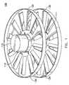
- FIG. 1shows a fin stack according to a first exemplary embodiment of the present invention.
- FIG. 2shows an individual fin disk according to a first exemplary embodiment of the present invention.
- FIG. 3shows the fin stack of FIG. 1, completely filled with fin disks.
- FIG. 4shows a cross-sectional view of the fin stack of FIG. 3 .
- FIG. 5shows a fin disk according to a second exemplary embodiment of the present invention.
- FIG. 6shows a fin disk according to a third exemplary embodiment of the present invention.
- FIG. 7shows a heat exchanger device according to a first exemplary embodiment of the present invention utilizing fin disks according to the first and second exemplary embodiments of the present invention.
- FIG. 8shows an magnified view of a portion of the heat exchanger device of FIG. 7 .
- FIG. 9shows a heat exchanger device according to a second exemplary embodiment of the present invention utilizing fin disks according to the first exemplary embodiment of the present invention.
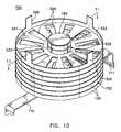
- FIG. 10shows a heat exchanger device according to a third exemplary embodiment of the present invention utilizing fin disks according to the first and third exemplary embodiments of the present invention.
- FIG. 11shows a cross-sectional view of the heat exchanger device shown in FIG. 10 .
- the present inventioncomprises an apparatus and method for removing heat from heat-producing equipment.
- the apparatus according to the exemplary embodiments of the present inventionis preferably coupled to a heat pipe, microprocessor, semiconductor device or other heat-producing member.
- a first exemplary embodiment of the present inventioncomprises a fin stack 100 and fin disks 120 .
- Fin stack 100is preferably utilized as an integral part of a heat exchanger apparatus 500 , which is explained in detail below with reference to FIGS. 7 and 8.
- Fin stack 100comprises an elongate post 110 that is centrally disposed on a plurality of fin disks 120 .
- Elongate post 110includes a base portion 111 and a column portion 112 , and is preferably formed from Copper (Cu) or some other heat conducting material.
- Fin disks 120include alignment notches 129 which are used for aligning the fin disks on elongate post 110 (as explained below with reference to FIG. 7 ).
- Fin disks 120are preferably formed of plastic, but may be formed of any suitable engineering material. Fin disks 120 are explained in more detail below with reference to FIG. 2 .
- FIG. 2shows a single fin disk 120 as discussed above with reference to FIG. 1 .
- Fin disk 120comprises a substantially circular base 121 having a continuous annular lip 122 disposed on its outer peripheral edge.
- Base 121also includes a centrally-disposed substantially circular opening 125 for receiving column portion 112 of elongate post 110 (See FIG. 1 ).
- a centrally-disposed annular lip 123including a plurality of slots 124 , surrounds opening 125 .
- Base 121also includes a plurality of flow openings 126 , and a plurality of flow guides 127 disposed adjacent flow openings 126 .
- Flow openings 126permit air to flow through the fin disks, and flow guides 127 assist in directing the air as it passes through the flow openings.
- Flow guides 127are preferably disposed at an angle between 0° and 90° with respect to the primary plane of circular base 121 . It will be noted that the flow guides 127 shown in FIG. 2 are disposed at an angle of approximately 45° with respect to the primary plane of the 121 .
- flow openings 126 of adjacent fin disks 120are preferably staggered with respect to one another so that a helical air flow path is created.
- flow openings 126 of fin disks 120 disposed on either side of a central fin disk 120are offset with respect to the flow openings of the central fin disk (i.e., the flow openings 126 are not directly overtop of each other in adjacent fin disks 120 ).
- fin disks 120preferably include alignment notches 129 for permitting alignment of the fin disks in such a manner (See FIGS. 1 and 7 ).
- FIGS. 1 and 2show fin disks 120 with flow guides 127 , these flow guides are not always required for operation of the present invention. If fin disks 120 were formed without the flow guides 127 , air would still flow therethrough. Additionally, although FIG. 2 shows the flow openings as substantially rectangular, round or elliptical flow openings may also be used without departing from the scope of the present invention.
- FIG. 3shows fin stack 100 with a plurality of fin disks 120 disposed thereon.
- continuous lips 122 of fin disks 120inter engage one another so as to mate with each other to form a substantially continuous wall which is concentric with elongate post 110 .
- the substantially continuous wall created by the interlocking of continuous lips 122 of fin disks 120prohibits air from escaping from fin stack 100 as it travels therethrough.
- each fin disk 120 in fin stack 100is preferably offset with respect to the fin disk on either side thereof. This arrangement allows air to flow through fin stack 100 in a substantially helical motion.
- air flowis typically from the bottom of the fin stack (i.e., where base portion 111 of elongate post 110 is disposed) to the top of the fin stack in a helical flow pattern.
- fin disks 120are all arranged so that flow guides 127 point in the same direction.
- fin disks 120may be arranged so that flow guides 127 face in opposite directions on successive fin disks.
- Such a structurewould permit the air flow to follow an undulating path through fin stack 100 , rather than the helical path discussed above.
- An undulating air flow pathmay have slightly better thermal performance than the helical path, however, the pressure drop for the path may be higher, and thus not a sufficient trade for the improved thermal performance.
- FIG. 5shows a fin disk 220 according to a second exemplary embodiment of the present invention.
- fin disk 220comprises a substantially circular base 221 with a continuous annular lip 222 disposed at its peripheral edge.
- Base 221also includes a centrally-disposed substantially circular opening 225 for receiving column portion 112 of elongate post 110 (See FIG. 1 ).
- a centrally-disposed lip 223including a plurality of slots 224 , surrounds opening 225 .
- Base 221also includes a plurality of flow openings 226 , and a plurality of flow guides 227 disposed adjacent the flow openings 226 .
- lip 222includes a plurality of circumferentially spaced tabs 228 .
- Tabs 228are utilized to secure fin disk 220 to a circulation device (e.g., fan). Because of tabs 228 , fin disk 220 may be used as the uppermost fin disk in a fin stack (See FIG. 7 ).
- flow openings 226permit air to flow through fin disk 220 , and flow guides 227 assist in directing the air as it passes through the flow openings.
- Flow guides 227are preferably disposed at an angle of between 0° and 90° with respect to the primary plane circular base 221 . It will be noted that flow guides 227 (FIG. 5) are disposed at an angle of approximately 45° with respect to the primary plane of base 221 . As noted above with respect to fin disk 120 , although fin disk 220 includes flow guides 227 , such flow guides are not required for adquate operation of the fin disk.
- FIG. 6shows a fin disk 320 according to a third exemplary embodiment of the present invention.
- fin disk 320comprises a substantially circular base 321 with a continuous annular lip 322 disposed on its peripheral edge.
- Base 321also includes a centrally-disposed substantially circular opening 325 sized to receive the column portion 112 of elongate post 110 (See FIG. 1 ).
- a centrally-disposed annular lip 323including a plurality of slots 324 , surrounds opening 325 .
- Base 321also includes a plurality of flow openings 326 .
- Flow guides 327are formed in fin disk 320 adjacent to flow openings 326 .
- fin disk 320includes a radially inwardly projecting notch 329 spanning the circumference of lip 323 which may be used for securing fin disk 320 to a metal post 750 (See FIGS. 10 - 11 ).
- Fin disk 320may not include flow guides.
- FIG. 7shows a heat exchanger apparatus 500 according to a first exemplary embodiment of the present invention.
- Heat exchanger 500includes a clip 510 for securing the heat exchanger to a heat-producing apparatus (not shown, e.g., a microprocessor), a circulation device 520 (e.g., fan), and a fin stack 530 .
- Fin stack 530is preferably comprised of a plurality of fin disks 120 according to a first exemplary embodiment of the present invention, and at least one fin disk 220 according to a second exemplary embodiment of the present invention.
- Circulation device 520preferably comprises a fan or other equivalent circulation means, with a central hub 523 and a plurality of fan blades 522 .
- Central hub 523includes a motor which powers circulation device 520 .
- Circulation device 520also preferably includes openings 521 for receiving tabs 228 of fin disk 220 .
- tabs 228may be bent back or otherwise deformed once circulation device 520 has been placed on fin disk 220 , so as to prevent the circulation device from moving away from the fin stack.
- caps or other securing membersmay be placed over tabs 228 in order to prevent circulation device 520 from being removed from fin stack 530 .
- each of fin disks 120includes an alignment notch 129 which assists in aligning fin disks 120 with respect to each other.
- FIG. 8shows a magnified view of a portion of one of the fin disks 120 , showing one of the alignment notches 129 in detail.
- alignment notches 129are offset with respect to each other as between adjacent fin disks 120 .
- All fin disks 120are manufactured with alignment notch 129 in the same position, and thus, by offsetting the notches between adjacent fin disks 120 , a helical air path may be created in fin stack 530 . This helical air path allows for a more efficient transfer of heat away from the heat-producing apparatus, through fin stack 530 , and out from circulation device 520 .
- circulation device 520creates an air flow through fin stack 530 in a direction away from clip 510 . Since clip 510 will be attached to a heat producing apparatus, this operation draws heat generated by the heat-producing apparatus away from the apparatus through fin stack 530 and toward circulation device 520 . This heated air then exits circulation device 520 on the side opposite fin stack 530 . Removal of such heated air from the air surrounding the heat-producing apparatus permits the apparatus to operate at higher temperatures. With respect to a microprocessor or semiconductor device, as the heat-producing apparatus, higher operating temperatures translate directly to more operations for the device per unit of time.
- FIG. 8shows an magnified view of a portion of fin disk 120 shown in FIG. 7 .
- This magnified viewshows that the fin disks each include an alignment notch 129 .
- this alignment notchis shown as being triangular shaped in FIG. 8, the alignment notch may be of any suitable geometric shape.
- FIG. 9shows a heat exchanger apparatus 600 according to a second exemplary embodiment of the present invention.
- Heat exchanger apparatus 600is similar to heat exchanger apparatus 500 , and like reference numerals denote like elements.
- Heat exchanger 600includes a clip 610 for securing the heat exchanger to a heat-producing apparatus (not shown, e.g., a microprocessor), a circulation device 620 (e.g., fan), and a fin stack 630 .
- Fin stack 630is preferably comprised of a plurality of fin disks 120 formed according to a first exemplary embodiment of the present invention. As opposed to fin stack 530 of heat exchanger apparatus 500 , fin stack 630 does not include a fin disk 220 .
- tabs 650 for securing circulation device 620are manufactured separately and secured to one of the fin disks 120 by means of screws, bolts, rivets, or other equivalent attachment means. As will be understood, tabs 650 may be similar in configuration to tabs 228 of fin disk 220 .
- FIGS. 10 and 11show heat exchanger apparatus 700 according to a third exemplary embodiment of the present invention.
- Heat exchanger apparatus 700is similar to heat exchanger apparatus 500 , and like reference numerals denote like elements.
- Heat exchanger 700includes a clip 710 for securing the heat exchanger to a heat-producing apparatus (not shown, e.g., a microprocessor), a circulation device (not shown, e.g., fan), and a fin stack 730 .
- Fin stack 730is preferably comprised of a plurality of fin disks 120 according to a first exemplary embodiment of the present invention, and at least one fin disk 320 according to the third exemplary embodiment of the present invention (See FIG. 6 ).
- elongate post 750includes an annular groove 751 for receiving notch 329 of fin disk 320 .
- the manner in which notch 329 is secured in the groove 751 of the elongate post 750may be discerned more easily by reference the cross-sectional view of the heat exchanger apparatus 700 shown in FIG. 11 .
- Forming an annular groove in the elongate post 750permits the uppermost fin disk 320 to be secured to the post without the need for screws, adhesives or other attachment means.
- elongate post 750may be provided with a thread (or other equivalent attachment means) at an upper portion which mates with a thread formed on the fin disk. Then, the fin disk may be screwed onto the elongate post to secure the fin disk thereto.
Landscapes
- Physics & Mathematics (AREA)
- Condensed Matter Physics & Semiconductors (AREA)
- General Physics & Mathematics (AREA)
- Engineering & Computer Science (AREA)
- Computer Hardware Design (AREA)
- Microelectronics & Electronic Packaging (AREA)
- Power Engineering (AREA)
- Cooling Or The Like Of Electrical Apparatus (AREA)
Abstract
Description
Claims (10)
Priority Applications (1)
| Application Number | Priority Date | Filing Date | Title |
|---|---|---|---|
| US10/300,094US6712128B1 (en) | 2002-11-20 | 2002-11-20 | Cylindrical fin tower heat sink and heat exchanger |
Applications Claiming Priority (1)
| Application Number | Priority Date | Filing Date | Title |
|---|---|---|---|
| US10/300,094US6712128B1 (en) | 2002-11-20 | 2002-11-20 | Cylindrical fin tower heat sink and heat exchanger |
Publications (1)
| Publication Number | Publication Date |
|---|---|
| US6712128B1true US6712128B1 (en) | 2004-03-30 |
Family
ID=31993662
Family Applications (1)
| Application Number | Title | Priority Date | Filing Date |
|---|---|---|---|
| US10/300,094Expired - Fee RelatedUS6712128B1 (en) | 2002-11-20 | 2002-11-20 | Cylindrical fin tower heat sink and heat exchanger |
Country Status (1)
| Country | Link |
|---|---|
| US (1) | US6712128B1 (en) |
Cited By (26)
| Publication number | Priority date | Publication date | Assignee | Title |
|---|---|---|---|---|
| US20040196632A1 (en)* | 2003-04-01 | 2004-10-07 | Chin-Ming Chen | Heat dissipation module |
| US20050077028A1 (en)* | 2003-10-08 | 2005-04-14 | Hironori Oikawa | Liquid cooling jacket |
| US20060219386A1 (en)* | 2005-04-01 | 2006-10-05 | Delta Electronics, Inc. | Heat dissipating assembly with composite heat dissipating structure |
| US20070119583A1 (en)* | 2005-11-29 | 2007-05-31 | Foster Jimmy G Sr | Heat sink for distributing a thermal load |
| US20070151712A1 (en)* | 2006-01-05 | 2007-07-05 | Foster Jimmy G Sr | Heat sink for distributing a thermal load |
| US20070151706A1 (en)* | 2006-01-05 | 2007-07-05 | International Business Machines Corporation | Heat sink for dissipating a thermal load |
| US20070240868A1 (en)* | 2006-04-17 | 2007-10-18 | Chaun-Choung Technology Corp. | Air-guiding structure for heat-dissipating fin |
| US20080066898A1 (en)* | 2006-09-15 | 2008-03-20 | Foxconn Technology Co., Ltd. | Heat dissipation device |
| US7347251B2 (en) | 2005-12-21 | 2008-03-25 | International Business Machines Corporation | Heat sink for distributing a thermal load |
| US20090107654A1 (en)* | 2007-10-26 | 2009-04-30 | Chin-Ming Chen | Heat dissipation module and base and manufacturing method thereof |
| US20090151901A1 (en)* | 2007-12-14 | 2009-06-18 | Asustek Computer Inc. | Fin and Heat Sink |
| USD619548S1 (en)* | 2009-07-21 | 2010-07-13 | Foxsemicon Intergrated Technology, Inc. | Heat dissipation device |
| USD619549S1 (en)* | 2009-07-21 | 2010-07-13 | Foxsemicon Integrated Technology, Inc. | Heat dissipation device |
| US20100181889A1 (en)* | 2009-01-16 | 2010-07-22 | Light Prescriptions Innovators, Llc | Heat sink with helical fins and electrostatic augmentation |
| US20100194179A1 (en)* | 2009-02-02 | 2010-08-05 | Goodrich Corporation | Thermal management composite heat shield |
| USD622675S1 (en)* | 2009-07-21 | 2010-08-31 | Foxsemicon Integrated Technology, Inc. | Heat dissipation device |
| US20110000648A1 (en)* | 2009-07-01 | 2011-01-06 | Chao-Nan Chien | Heat dissipation module |
| US20110114301A1 (en)* | 2009-11-19 | 2011-05-19 | Fu Zhun Precision Industry (Shen Zhen) Co., Ltd. | Heat dissipation apparatus and method for manufacturing the same |
| US20120261096A1 (en)* | 2011-04-12 | 2012-10-18 | Asia Vital Components Co., Ltd. | Radiating fin structureand thermal module using same |
| WO2013043263A1 (en) | 2011-09-06 | 2013-03-28 | Vacuum Process Engineering, Inc. | Heat exchanger produced from laminar elements |
| US8480262B2 (en)* | 2011-03-09 | 2013-07-09 | Amtran Technology Co., Ltd. | Light profile controllable light emitting device |
| US20150211807A1 (en)* | 2014-01-29 | 2015-07-30 | Trane International Inc. | Heat Exchanger with Fluted Fin |
| US20150354908A1 (en)* | 2014-06-05 | 2015-12-10 | Zoneflow Reactor Technologies, LLC | Engineered packing for heat exchange and systems and methods for constructing the same |
| US9735083B1 (en)* | 2016-04-18 | 2017-08-15 | International Business Machines Corporation | Adjustable heat sink fin spacing |
| CN107131157A (en)* | 2017-04-12 | 2017-09-05 | 唐山达创科技有限公司 | Heat sink and swing structure thereof |
| US10031565B1 (en)* | 2017-01-06 | 2018-07-24 | Evga Corporation | Heat dissipation structure of addin card |
Citations (18)
| Publication number | Priority date | Publication date | Assignee | Title |
|---|---|---|---|---|
| US2879976A (en)* | 1956-04-12 | 1959-03-31 | Heat saver | |
| FR1467264A (en)* | 1965-12-17 | 1967-01-27 | heat exchange element | |
| US3457988A (en)* | 1967-05-15 | 1969-07-29 | Westinghouse Electric Corp | Integral heat sink for semiconductor devices |
| US3537517A (en)* | 1968-03-29 | 1970-11-03 | Gen Electric | Heat dissipating assembly |
| US4715438A (en) | 1986-06-30 | 1987-12-29 | Unisys Corporation | Staggered radial-fin heat sink device for integrated circuit package |
| US4733293A (en) | 1987-02-13 | 1988-03-22 | Unisys Corporation | Heat sink device assembly for encumbered IC package |
| US4753290A (en) | 1986-07-18 | 1988-06-28 | Unisys Corporation | Reduced-stress heat sink device |
| US5132780A (en) | 1988-01-07 | 1992-07-21 | Prime Computer, Inc. | Heat sink apparatus with an air deflection member |
| US5351166A (en)* | 1991-12-30 | 1994-09-27 | Goldstar Co., Ltd. | Cooling apparatus of magnetrons |
| US5484013A (en) | 1993-05-27 | 1996-01-16 | Nippon Densan Corporation | Heat sink fan |
| US5523918A (en) | 1995-07-31 | 1996-06-04 | Chiou; Ming D. | CPU heat dissipating apparatus |
| US5661638A (en) | 1995-11-03 | 1997-08-26 | Silicon Graphics, Inc. | High performance spiral heat sink |
| US5784257A (en) | 1997-02-21 | 1998-07-21 | Chip Coolers, Inc. | Heatsink assembly with adjustable retaining clip |
| US5943209A (en) | 1997-10-06 | 1999-08-24 | Liu; Yen-Wen | Modularized electronic component cooling apparatus |
| EP1081760A2 (en) | 1999-08-30 | 2001-03-07 | Molex Incorporated | Heat sink assembly |
| US6199624B1 (en) | 1999-04-30 | 2001-03-13 | Molex Incorporated | Folded fin heat sink and a heat exchanger employing the heat sink |
| US6360816B1 (en)* | 1999-12-23 | 2002-03-26 | Agilent Technologies, Inc. | Cooling apparatus for electronic devices |
| US6450250B2 (en)* | 1999-06-11 | 2002-09-17 | Psc Computer Products, Inc. | Stackable heat sink for electronic components |
- 2002
- 2002-11-20USUS10/300,094patent/US6712128B1/ennot_activeExpired - Fee Related
Patent Citations (18)
| Publication number | Priority date | Publication date | Assignee | Title |
|---|---|---|---|---|
| US2879976A (en)* | 1956-04-12 | 1959-03-31 | Heat saver | |
| FR1467264A (en)* | 1965-12-17 | 1967-01-27 | heat exchange element | |
| US3457988A (en)* | 1967-05-15 | 1969-07-29 | Westinghouse Electric Corp | Integral heat sink for semiconductor devices |
| US3537517A (en)* | 1968-03-29 | 1970-11-03 | Gen Electric | Heat dissipating assembly |
| US4715438A (en) | 1986-06-30 | 1987-12-29 | Unisys Corporation | Staggered radial-fin heat sink device for integrated circuit package |
| US4753290A (en) | 1986-07-18 | 1988-06-28 | Unisys Corporation | Reduced-stress heat sink device |
| US4733293A (en) | 1987-02-13 | 1988-03-22 | Unisys Corporation | Heat sink device assembly for encumbered IC package |
| US5132780A (en) | 1988-01-07 | 1992-07-21 | Prime Computer, Inc. | Heat sink apparatus with an air deflection member |
| US5351166A (en)* | 1991-12-30 | 1994-09-27 | Goldstar Co., Ltd. | Cooling apparatus of magnetrons |
| US5484013A (en) | 1993-05-27 | 1996-01-16 | Nippon Densan Corporation | Heat sink fan |
| US5523918A (en) | 1995-07-31 | 1996-06-04 | Chiou; Ming D. | CPU heat dissipating apparatus |
| US5661638A (en) | 1995-11-03 | 1997-08-26 | Silicon Graphics, Inc. | High performance spiral heat sink |
| US5784257A (en) | 1997-02-21 | 1998-07-21 | Chip Coolers, Inc. | Heatsink assembly with adjustable retaining clip |
| US5943209A (en) | 1997-10-06 | 1999-08-24 | Liu; Yen-Wen | Modularized electronic component cooling apparatus |
| US6199624B1 (en) | 1999-04-30 | 2001-03-13 | Molex Incorporated | Folded fin heat sink and a heat exchanger employing the heat sink |
| US6450250B2 (en)* | 1999-06-11 | 2002-09-17 | Psc Computer Products, Inc. | Stackable heat sink for electronic components |
| EP1081760A2 (en) | 1999-08-30 | 2001-03-07 | Molex Incorporated | Heat sink assembly |
| US6360816B1 (en)* | 1999-12-23 | 2002-03-26 | Agilent Technologies, Inc. | Cooling apparatus for electronic devices |
Non-Patent Citations (3)
| Title |
|---|
| Molex Brochure; Thermal Acoustic Products Application Specification; 7 page; Jan. 2001. |
| Molex Brochure; Thermal Acoustic Products; 8 pages; 2001. |
| Molex.com; 4 internet pages; Thermal Acoustic Products, Aug. 2001. |
Cited By (44)
| Publication number | Priority date | Publication date | Assignee | Title |
|---|---|---|---|---|
| US20040196632A1 (en)* | 2003-04-01 | 2004-10-07 | Chin-Ming Chen | Heat dissipation module |
| US20050077028A1 (en)* | 2003-10-08 | 2005-04-14 | Hironori Oikawa | Liquid cooling jacket |
| US7021367B2 (en)* | 2003-10-08 | 2006-04-04 | Hitachi, Ltd. | Liquid cooling jacket |
| US20060219386A1 (en)* | 2005-04-01 | 2006-10-05 | Delta Electronics, Inc. | Heat dissipating assembly with composite heat dissipating structure |
| US20070119583A1 (en)* | 2005-11-29 | 2007-05-31 | Foster Jimmy G Sr | Heat sink for distributing a thermal load |
| US7347251B2 (en) | 2005-12-21 | 2008-03-25 | International Business Machines Corporation | Heat sink for distributing a thermal load |
| US20070151706A1 (en)* | 2006-01-05 | 2007-07-05 | International Business Machines Corporation | Heat sink for dissipating a thermal load |
| US20110192577A1 (en)* | 2006-01-05 | 2011-08-11 | International Business Machines Corporation | Heat Sink For Dissipating A Thermal Load |
| US20070151712A1 (en)* | 2006-01-05 | 2007-07-05 | Foster Jimmy G Sr | Heat sink for distributing a thermal load |
| US9230881B2 (en) | 2006-01-05 | 2016-01-05 | International Business Machines Corporation | Heat sink for dissipating a thermal load |
| US8230908B2 (en) | 2006-01-05 | 2012-07-31 | International Business Machines Corporation | Heat sink for dissipating a thermal load |
| US20070240868A1 (en)* | 2006-04-17 | 2007-10-18 | Chaun-Choung Technology Corp. | Air-guiding structure for heat-dissipating fin |
| US20080066898A1 (en)* | 2006-09-15 | 2008-03-20 | Foxconn Technology Co., Ltd. | Heat dissipation device |
| US20090107654A1 (en)* | 2007-10-26 | 2009-04-30 | Chin-Ming Chen | Heat dissipation module and base and manufacturing method thereof |
| US20090151901A1 (en)* | 2007-12-14 | 2009-06-18 | Asustek Computer Inc. | Fin and Heat Sink |
| WO2010083268A3 (en)* | 2009-01-16 | 2010-09-30 | Light Prescriptions Innovators, Llc | Heat sink with helical fins and electrostatic augmentation |
| US20100181889A1 (en)* | 2009-01-16 | 2010-07-22 | Light Prescriptions Innovators, Llc | Heat sink with helical fins and electrostatic augmentation |
| US8354779B2 (en) | 2009-01-16 | 2013-01-15 | Light Prescriptions Innovators Llc | Heat sink with helical fins and electrostatic augmentation |
| US9718447B2 (en)* | 2009-02-02 | 2017-08-01 | Goodrich Corporation | Thermal management composite heat shield |
| US20100194179A1 (en)* | 2009-02-02 | 2010-08-05 | Goodrich Corporation | Thermal management composite heat shield |
| US20110000648A1 (en)* | 2009-07-01 | 2011-01-06 | Chao-Nan Chien | Heat dissipation module |
| USD622675S1 (en)* | 2009-07-21 | 2010-08-31 | Foxsemicon Integrated Technology, Inc. | Heat dissipation device |
| USD619549S1 (en)* | 2009-07-21 | 2010-07-13 | Foxsemicon Integrated Technology, Inc. | Heat dissipation device |
| USD619548S1 (en)* | 2009-07-21 | 2010-07-13 | Foxsemicon Intergrated Technology, Inc. | Heat dissipation device |
| US20110114301A1 (en)* | 2009-11-19 | 2011-05-19 | Fu Zhun Precision Industry (Shen Zhen) Co., Ltd. | Heat dissipation apparatus and method for manufacturing the same |
| CN102076205A (en)* | 2009-11-19 | 2011-05-25 | 富准精密工业(深圳)有限公司 | A heat radiation apparatus and a manufacturing method for the same |
| US8408285B2 (en)* | 2009-11-19 | 2013-04-02 | Fu Zhun Precision Industry (Shen Zhen) Co., Ltd. | Heat dissipation apparatus |
| US8480262B2 (en)* | 2011-03-09 | 2013-07-09 | Amtran Technology Co., Ltd. | Light profile controllable light emitting device |
| US20120261096A1 (en)* | 2011-04-12 | 2012-10-18 | Asia Vital Components Co., Ltd. | Radiating fin structureand thermal module using same |
| WO2013043263A1 (en) | 2011-09-06 | 2013-03-28 | Vacuum Process Engineering, Inc. | Heat exchanger produced from laminar elements |
| US20150211807A1 (en)* | 2014-01-29 | 2015-07-30 | Trane International Inc. | Heat Exchanger with Fluted Fin |
| US20150354908A1 (en)* | 2014-06-05 | 2015-12-10 | Zoneflow Reactor Technologies, LLC | Engineered packing for heat exchange and systems and methods for constructing the same |
| US9677828B2 (en)* | 2014-06-05 | 2017-06-13 | Zoneflow Reactor Technologies, Llp | Engineered packing for heat exchange and systems and methods constructing the same |
| US9735083B1 (en)* | 2016-04-18 | 2017-08-15 | International Business Machines Corporation | Adjustable heat sink fin spacing |
| US9921008B2 (en) | 2016-04-18 | 2018-03-20 | International Business Machines Corporation | Adjustable heat sink fin spacing |
| US10088244B2 (en) | 2016-04-18 | 2018-10-02 | International Business Machines Corporation | Adjustable heat sink fin spacing |
| US10584924B2 (en) | 2016-04-18 | 2020-03-10 | International Business Machines Corporation | Adjustable heat sink fin spacing |
| US10948247B2 (en) | 2016-04-18 | 2021-03-16 | International Business Machines Corporation | Adjustable heat sink fin spacing |
| US11035625B2 (en) | 2016-04-18 | 2021-06-15 | International Business Machines Corporation | Adjustable heat sink fin spacing |
| US10031565B1 (en)* | 2017-01-06 | 2018-07-24 | Evga Corporation | Heat dissipation structure of addin card |
| KR20190002402U (en)* | 2017-01-06 | 2019-09-27 | 이브이지에이 코포레이션 | Heat dissipation structure of interface card |
| KR200490663Y1 (en) | 2017-01-06 | 2019-12-12 | 이브이지에이 코포레이션 | Heat dissipation structure of interface card |
| CN107131157A (en)* | 2017-04-12 | 2017-09-05 | 唐山达创科技有限公司 | Heat sink and swing structure thereof |
| CN107131157B (en)* | 2017-04-12 | 2023-07-28 | 唐山达创科技有限公司 | Heat dissipating device and swing structure thereof |
Similar Documents
| Publication | Publication Date | Title |
|---|---|---|
| US6712128B1 (en) | Cylindrical fin tower heat sink and heat exchanger | |
| US8408285B2 (en) | Heat dissipation apparatus | |
| US6450250B2 (en) | Stackable heat sink for electronic components | |
| CN1187816C (en) | Wave type fin radiator and heat exchange using this radiator | |
| KR101472642B1 (en) | Cooling module for cooling electronic components | |
| US5727624A (en) | CPU heat dissipating device with airguiding units | |
| EP3722722B1 (en) | Curved heat exchanger | |
| US6543522B1 (en) | Arrayed fin cooler | |
| US5886870A (en) | Heat sink device | |
| CN100518468C (en) | heat sink | |
| EP0892431A2 (en) | Heat radiating plate | |
| US6459580B1 (en) | Cooling system for removing heat from an object | |
| US11985797B2 (en) | Cooling device for dissipating heat from an object | |
| US20080017350A1 (en) | Heat sink | |
| KR20090004710A (en) | Heat sink and cooling unit | |
| US20030034150A1 (en) | Radial folded fin heat sink | |
| CN102111985A (en) | Heat-dissipating device | |
| US20040200608A1 (en) | Plate fins with vanes for redirecting airflow | |
| JP5567076B2 (en) | Radiator | |
| EP3734655B1 (en) | High efficiency integrated ax-radial blower and heat exchanger | |
| US7055577B2 (en) | Heat dissipation device for electronic device | |
| JP2009099740A (en) | Housing cooling device | |
| GB2511367A (en) | Bi-directional heat dissipation structure | |
| US6205662B1 (en) | Method of producing a built-up heat exchanger and product thereof | |
| US20080024994A1 (en) | Combination heat sink |
Legal Events
| Date | Code | Title | Description |
|---|---|---|---|
| AS | Assignment | Owner name:THERMAL CORP., DELAWARE Free format text:ASSIGNMENT OF ASSIGNORS INTEREST;ASSIGNORS:DUSSINGER, PETER M.;SARRAF, DAVID;REEL/FRAME:013512/0043;SIGNING DATES FROM 20021108 TO 20021113 | |
| FEPP | Fee payment procedure | Free format text:PAYOR NUMBER ASSIGNED (ORIGINAL EVENT CODE: ASPN); ENTITY STATUS OF PATENT OWNER: SMALL ENTITY | |
| CC | Certificate of correction | ||
| FPAY | Fee payment | Year of fee payment:4 | |
| REMI | Maintenance fee reminder mailed | ||
| FEPP | Fee payment procedure | Free format text:PAYER NUMBER DE-ASSIGNED (ORIGINAL EVENT CODE: RMPN); ENTITY STATUS OF PATENT OWNER: SMALL ENTITY Free format text:PAYOR NUMBER ASSIGNED (ORIGINAL EVENT CODE: ASPN); ENTITY STATUS OF PATENT OWNER: SMALL ENTITY | |
| AS | Assignment | Owner name:NATIONAL PENN BANK, PENNSYLVANIA Free format text:SECURITY AGREEMENT;ASSIGNORS:THERMAL CORP.;FSBO VENTURE ACQUISITIONS, INC.;REEL/FRAME:021398/0300 Effective date:20080430 Owner name:NATIONAL PENN BANK,PENNSYLVANIA Free format text:SECURITY AGREEMENT;ASSIGNORS:THERMAL CORP.;FSBO VENTURE ACQUISITIONS, INC.;REEL/FRAME:021398/0300 Effective date:20080430 | |
| FEPP | Fee payment procedure | Free format text:PAT HOLDER CLAIMS SMALL ENTITY STATUS, ENTITY STATUS SET TO SMALL (ORIGINAL EVENT CODE: LTOS); ENTITY STATUS OF PATENT OWNER: SMALL ENTITY | |
| AS | Assignment | Owner name:SOVEREIGN BANK, PENNSYLVANIA Free format text:SECURITY AGREEMENT;ASSIGNORS:THERMACORE, INC.;THERMAL CORP.;REEL/FRAME:026039/0865 Effective date:20101230 | |
| FPAY | Fee payment | Year of fee payment:8 | |
| AS | Assignment | Owner name:PINE STREET CAPITAL PARTNERS II, L.P., NEW YORK Free format text:SECURITY INTEREST;ASSIGNOR:THERMAL CORP.;REEL/FRAME:035134/0363 Effective date:20141113 | |
| REMI | Maintenance fee reminder mailed | ||
| LAPS | Lapse for failure to pay maintenance fees | ||
| STCH | Information on status: patent discontinuation | Free format text:PATENT EXPIRED DUE TO NONPAYMENT OF MAINTENANCE FEES UNDER 37 CFR 1.362 | |
| FP | Lapsed due to failure to pay maintenance fee | Effective date:20160330 | |
| AS | Assignment | Owner name:THERMAL CORP., NEW HAMPSHIRE Free format text:RELEASE OF SECURITY INTEREST RECORDED AT REEL/FRAME 035134/0363;ASSIGNOR:PINE STREET CAPITAL PARTNERS II, L.P.;REEL/FRAME:040425/0584 Effective date:20161013 | |
| AS | Assignment | Owner name:THERMACORE, INC., PENNSYLVANIA Free format text:RELEASE OF SECURITY INTEREST RECORDED AT REEL/FRAME 026039/0865;ASSIGNOR:SANTANDER BANK, N.A. F/K/A SOVEREIGN BANK;REEL/FRAME:040508/0649 Effective date:20161013 Owner name:THERMACORE, INC. F/K/A FSBO VENTURE ACQUISITIONS, Free format text:RELEASE OF SECURITY INTEREST RECORDED AT REEL/FRAME 021398/0300;ASSIGNOR:NATIONAL PENN BANK;REEL/FRAME:040508/0620 Effective date:20101230 Owner name:THERMAL CORP., NEW HAMPSHIRE Free format text:RELEASE OF SECURITY INTEREST RECORDED AT REEL/FRAME 026039/0865;ASSIGNOR:SANTANDER BANK, N.A. F/K/A SOVEREIGN BANK;REEL/FRAME:040508/0649 Effective date:20161013 Owner name:THERMAL CORP., NEW HAMPSHIRE Free format text:RELEASE OF SECURITY INTEREST RECORDED AT REEL/FRAME 021398/0300;ASSIGNOR:NATIONAL PENN BANK;REEL/FRAME:040508/0620 Effective date:20101230 |