US6712057B2 - Archery bow assembly - Google Patents
Archery bow assemblyDownload PDFInfo
- Publication number
- US6712057B2 US6712057B2US10/256,623US25662302AUS6712057B2US 6712057 B2US6712057 B2US 6712057B2US 25662302 AUS25662302 AUS 25662302AUS 6712057 B2US6712057 B2US 6712057B2
- Authority
- US
- United States
- Prior art keywords
- riser
- strut
- limb
- archery bow
- set forth
- Prior art date
- Legal status (The legal status is an assumption and is not a legal conclusion. Google has not performed a legal analysis and makes no representation as to the accuracy of the status listed.)
- Expired - Fee Related
Links
- 239000006096absorbing agentSubstances0.000claimsdescription5
- 230000000717retained effectEffects0.000claimsdescription5
- 230000035939shockEffects0.000claimsdescription5
- 230000008901benefitEffects0.000description2
- 150000001875compoundsChemical class0.000description2
- 230000000712assemblyEffects0.000description1
- 238000000429assemblyMethods0.000description1
- 230000006835compressionEffects0.000description1
- 238000007906compressionMethods0.000description1
- 230000004048modificationEffects0.000description1
- 238000012986modificationMethods0.000description1
- 238000000926separation methodMethods0.000description1
- 238000010008shearingMethods0.000description1
- 125000006850spacer groupChemical group0.000description1
Images


Classifications
- F—MECHANICAL ENGINEERING; LIGHTING; HEATING; WEAPONS; BLASTING
- F41—WEAPONS
- F41B—WEAPONS FOR PROJECTING MISSILES WITHOUT USE OF EXPLOSIVE OR COMBUSTIBLE PROPELLANT CHARGE; WEAPONS NOT OTHERWISE PROVIDED FOR
- F41B5/00—Bows; Crossbows
- F41B5/0005—Single stave recurve bows
- F41B5/0026—Take-down or foldable bows
- F—MECHANICAL ENGINEERING; LIGHTING; HEATING; WEAPONS; BLASTING
- F41—WEAPONS
- F41B—WEAPONS FOR PROJECTING MISSILES WITHOUT USE OF EXPLOSIVE OR COMBUSTIBLE PROPELLANT CHARGE; WEAPONS NOT OTHERWISE PROVIDED FOR
- F41B5/00—Bows; Crossbows
- F41B5/10—Compound bows
- F—MECHANICAL ENGINEERING; LIGHTING; HEATING; WEAPONS; BLASTING
- F41—WEAPONS
- F41B—WEAPONS FOR PROJECTING MISSILES WITHOUT USE OF EXPLOSIVE OR COMBUSTIBLE PROPELLANT CHARGE; WEAPONS NOT OTHERWISE PROVIDED FOR
- F41B5/00—Bows; Crossbows
- F41B5/14—Details of bows; Accessories for arc shooting
- F41B5/1403—Details of bows
- F41B5/1426—Bow stabilisers or vibration dampers
Definitions
- the present inventionrelates to archery bow assemblies, and more particularly, to a strut assembly for mounting the limbs of the bow to the riser.
- Archery bowstypically include a riser defining a handle for holding the bow and a pair of limbs extending from opposite ends of the riser to distal ends.
- a wheel or camis commonly rotatably attached to the distal end of each limb and a string and harness system is wound between the wheels or cams of the limbs.
- the limbsare often flexed and the string and harness system is loaded under high tension to define the draw weight or force required to pull the string of the bow to its full draw position.
- the draw weight of the bowmay be changed by attaching a different length string between the wheels or cams or by change the angle or orientation of the limbs relative to the bow. It is common to connect the limbs of the bow to the riser with a bolt or connector which extends through the limb and is threaded into the riser. The connector may be loosened to change the orientation of the limbs on the riser and slightly adjust the draw weight of the bow. However, significant shearing forces are exerted on the connector as the orientation of the limbs relative to the riser is changed. Additionally, the connector does not allow the bow to be assembled or disassembled without the use of a bow press.
- an archery bowcomprising a riser extending between opposing first and second ends.
- a limbis coupled to each end of the riser.
- Each limbhas a first end for connecting to the riser and a second distal end.
- An axlepivotally connects at least one of the limbs to one end of the riser.
- a strut assemblyis operatively coupled between at least one of the limbs and the riser adjacent the axle for selectively pivoting the limb relative to the riser thereby allowing manual assembly and tuning of the bow by varying the distance between the distal ends of the limbs.
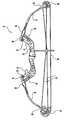
- FIG. 1is a side view of an archery bow assembly according to one aspect of the invention
- FIG. 2is a fragmentary exploded view of the archery bow assembly and strut assembly for attaching the limbs to the riser;
- FIG. 3is an enlarged perspective view of the strut assembly connected between the limb and the riser;
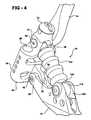
- FIG. 4is another enlarged perspective view of the strut assembly connected between the limb and the riser with a portion of the limb removed;
- FIG. 5is a cross-sectional view of the strut assembly between the limb and riser.
- FIG. 1illustrates a compound archery bow 10 having a riser 12 with a pair of limbs 14 , 16 extending from opposing ends 18 , 20 of the riser 12 .
- the limb 14has a first end 22 connected to the end 18 of the riser 12 and a second distal end 24 .
- the limb 16has a first end 26 connected to the opposite end 20 of the riser 12 and a second distal end 28 .
- a wheel or cam 30 , 32is rotatably attached to each distal end 24 , 28 of the limbs 14 , 16 .
- a harness or cable system 34 and bow string 36are wound around and between each wheel or cam 30 , 32 and pulled in tension by the limbs 14 , 16 .
- the bow 10further includes a pair of limb pockets 38 , 40 for pivotally attaching the respective limbs 14 , 16 to the opposing ends 18 , 20 of the riser 12 .
- a pocket axle 42pivotally couples each of the respective limbs pockets 38 , 40 to the opposing ends 18 , 20 .
- a strut assembly 44adjustably couples each of the limb pockets 38 , 40 to the opposing ends 18 , 20 of the riser.
- the strut assembly 44allows for assembly and disassembly of the limbs 14 , 16 and limb pockets 38 , 40 to the riser 12 as well as the harness system 34 and string 36 between the wheels or cams 30 , 32 .
- the strut assembly 44further allows for selective micro-tuning and adjustment of the bow 10 , such as for example, the adjustment of the bow's draw weight and/or axle to axle length between the wheels or cams 30 , 32 .
- the strut assembly 44includes an adjustable threaded strut power screw 46 coupled to and between the limb pocket 38 and the end 18 of the riser 12 .
- the end 18 of the riser 12includes an extended pair of spaced apart fingers 48 , 50 each having a bore 52 therethrough for receiving the pocket axle 42 and pivotally securing the limb pocket 38 to the riser 12 .
- the limb pocket 38includes a base 54 having a pivot post 56 extending therefrom with a through bore 58 .
- the pivot post 56is seated between the fingers 48 , 50 and the bores 52 , 58 aligned axially to receive the pocket axle 42 therethrough.
- a spacer 60is received on each side of the pivot post 56 around the axle 42 and an end cap or bushing 62 is secured to the distal end of the pocket axle 42 to pivotally secure the limb pocket 38 to the riser 12 while allowing pivotal movement of the limb 14 and limb pocket 38 about the pocket axle 42 and end 18 of the riser 12 .
- Each limb 14 , 16may be a single unitary member, may be two spaced apart members or may be a split limb, as shown in FIG. 2, with a pair of substantially separate and parallel spaced apart limb posts 64 connected to a main member 66 .
- the base 54 of the limb pocket 38includes spaced apart tunnels 68 for receiving and mounting the limb posts 64 to the limb pocket 38 along the longitudinal length thereof.
- the limb posts 64may be secured to the limb pocket 38 by any suitable means.
- the limb pocket 38further includes a pair of spaced apart support posts 70 , 72 extending longitudinally from the base 54 and attached by an end cap 74 .
- Each support post 70 , 72includes a bore 76 therethrough, the axis of which is parallel to the pocket axle 42 .
- a cylindrical strut pivoting power screw nut 78is seated in each bore 76 between the spaced apart and parallel support posts 70 , 72 .
- the screw nut 78includes a longitudinal bore 80 extending therethrough and a transverse bore 82 extending perpendicular to the bore 80 for receiving the strut power screw 46 .
- Each of the bores 80 , 82are threaded and the screw nut 78 is freely rotatably seated in the bores 76 of the support posts 70 , 72 .
- the power screw 46is threaded through the bore 82 toward the riser 12 and retained in the limb pocket 38 by the screw nut 78 .
- a ball plunger 84is threaded into the bore 80 as shown in FIGS. 2 and 5.
- the ball plunger 84includes a compression spring 86 seated between a cap 88 and ball bearing 90 .
- the ball plunger 84is biased against the power screw 46 for indexing the rotational position of the power screw 46 relative to the screw nut 78 as will be further described hereinbelow.
- the strut power screw 46is a cylindrical threaded rod extending longitudinally between a first nut end 92 and a second distal end 94 having a concave recess 96 therein.
- the power screw 46further includes a row of spaced apart indexing holes or recesses 98 extending along the longitudinal extent of the screw 46 for engagement with the ball plunger 84 .
- the power screw 46may include one or more rows of indexing holes 98 around the perimeter of the screw 46 at any number of spaced apart degrees of separation with the individual holes 98 spaced apart longitudinally as desired.
- the screwmay include two parallel rows of indexing holes 98 spaced apart 180 degrees; three rows spaced apart 120 degree; four row spaced apart 90, etc.
- first strut shock absorber washer 100a cylindrical resilient strut shock absorber 102 (which is corrogated as shown) and a second strut shock absorber washer 104 .
- the riser 12further includes spaced apart flanges 106 , 108 each having a hole 110 therethrough with the axes of which are parallel to the axis of the pocket axle 42 .
- a cylindrical strut power screw ball bearing retainer 112is rotatably seated between the flanges 106 , 108 and aligned axially with the holes 110 .
- the retainer 112includes an axial bore 114 aligned with the holes 110 and a transverse bore 116 extending perpendicular to and through the axial bore 114 for receiving the distal end 94 of the power screw 46 .
- the strut assembly 44includes a cylindrical strut pivot support 118 dimensioned to be rotatably received in the axial bore 114 of the retainer 112 and holes 110 of the riser flanges 106 , 108 .
- the strut pivot support 118includes a recessed detent 120 in the periphery outer wall thereof for seating and supporting a ball bearing 122 .
- the second distal end 94 of the power screw 46is inserted through the transverse bore 116 in the ball bearing retainer 112 and the ball bearing 122 is rotatably seated between the recess 96 in the end of the power screw 46 and the detent 120 in the pivot support 118 to facilitate rotation of the strut power screw 46 .
- the strut assembly 44enables the end user of the archery bow 10 to assemble, disassembly and micro-tune or selectively adjust the characteristics of the bow 10 without the necessity of a conventional bow press typically used to compress the bow limbs and allow removal of the cables and string. More specifically, once the limbs 14 , 16 are secured to the limb pockets 38 , 40 , the limb pockets 38 , 40 may be pivotally attached to the opposing ends 18 , 20 of the riser 12 . The strut assembly 44 is then coupled between the limb pockets 38 , 40 and each end 18 , 20 of the riser 12 .
- the wheels or cams 30 , 32may be assembled to the distal ends of the limbs 14 , 16 and then the harness or cable system 34 and string 36 are attached to the wheels or cams 30 , 32 .
- the strut assembly 44allows the limbs 14 , 16 to be pivoted toward the riser 12 to reduce the distance between the distal ends of the limbs 14 , 16 for attachment of the harness 34 and string 36 without tension.
- the nut end 92 of the strut power screw 46may be rotated using a ratchet or wrench in a clockwise direction as shown in the drawings to increase the angle between the limbs 14 , 16 and riser 12 until the limbs 14 , 16 start to flex naturally due to the fixed length of the string 36 and harness 34 coupled between the wheels 30 , 32 .
- Rotating the strut power screw 46forces the power screw nut 78 to travel longitudinally along the threaded length of the screw 46 and pivot the limb pocket 38 , 40 about the pocket axle 42 and riser 12 .
- the strut shock absorber 102which encases and protects the strut power screw 46 may be compressed between the limb pockets 38 , 40 and riser 12 to allow pivotal movement of the limbs 14 , 16 while preventing dirt and debris from entering the strut assembly 44 .
- the strut power screw 46is simply rotated in the opposite, or counter-clockwise direction as shown, so that the screw nut 78 travels down the length of the screw 46 pivoting the limb pocket 38 , 40 about the pocket axle 42 and riser 12 until the tension on the string 36 and harness 34 is loosened.
- the bow 10may then be fully disassembled or part may be changed such as the string 36 without the need of a bow press to release the flex and tension on the limbs 14 , 16 and string 36 .
- the strut assembly 44also allows selective adjustment of the bow 10 by rotation of the strut power screw 46 in either the clockwise or counterclockwise direction.
- the screw nut 78travels along the length of the threaded power screw 46 forcing the limb pocket 38 , 40 to pivot about the riser 12
- the ball plunger 84follows the outer perimeter of the power screw 46 and engages with each indexing holes 98 along the length of the power screw 46 .
- the bow 10may be selectively adjusted by pivoting or tuning each limb 14 , 16 position relative to the riser 12 to adjust the tension on the string 36 and the flex of the limbs 14 , 16 which account for the draw weight of the bow 10 and also the axle to axle length defined between the wheels or cams 30 , 32 .
- the location of the ball plunger 84 along the indexing holes 98is maintain absent additional rotation of the power screw 46 . Therefore, by identifying the desired reference of the ball plunger 84 along the indexing holes 98 , the user may re-establish this adjustment after assembly and disassembly or after further tuning without having to go back to the factory recommended settings.
- the usermay selective adjust the bow 10 for different shooting conditions.
- the strut assembly 44allows the user to adjust the axle to axle distance to 37 inches during target practice and then adjust the axle to axle distance to 34 inches for hunting.
- the strut assembly 44also allows the user to selectively adjust the bow draw weight infinitely by rotating the power screw 46 and pivoting the limbs 14 , 16 relative to the riser 12 .
- the strut assemblymay be used on a recurve bow, compound bow or cross bow without varying from the invention. Additionally, the strut assembly may be coupled between only one of the limbs and the riser or both of the limbs and the riser. That is, one of the limbs may be fixedly attached to one end of the riser and the other limb pivotally attached to the opposite end of the riser with the strut assembly extending therebetween to selectively pivot the one limb relative to the riser sufficient to release the tension on the string and allow assembly, disassembly and tuning of the bow.
- strut pivoting power screw nut 78may be retained in the riser 12 and the strut pivot support 118 retained by the limb 14 or limb pocket 38 without varying from the scope of the invention or function of the strut assembly 44 .
Landscapes
- Engineering & Computer Science (AREA)
- General Engineering & Computer Science (AREA)
- Rehabilitation Tools (AREA)
Abstract
Description
Claims (16)
Priority Applications (2)
| Application Number | Priority Date | Filing Date | Title |
|---|---|---|---|
| US10/256,623US6712057B2 (en) | 2001-09-27 | 2002-09-27 | Archery bow assembly |
| US10/712,193US6786214B2 (en) | 2002-09-27 | 2003-11-13 | Bow actuating system |
Applications Claiming Priority (2)
| Application Number | Priority Date | Filing Date | Title |
|---|---|---|---|
| US32537601P | 2001-09-27 | 2001-09-27 | |
| US10/256,623US6712057B2 (en) | 2001-09-27 | 2002-09-27 | Archery bow assembly |
Related Child Applications (2)
| Application Number | Title | Priority Date | Filing Date |
|---|---|---|---|
| US10/712,193Continuation-In-PartUS6786214B2 (en) | 2002-09-27 | 2003-11-13 | Bow actuating system |
| US10/712,193ContinuationUS6786214B2 (en) | 2002-09-27 | 2003-11-13 | Bow actuating system |
Publications (2)
| Publication Number | Publication Date |
|---|---|
| US20030084893A1 US20030084893A1 (en) | 2003-05-08 |
| US6712057B2true US6712057B2 (en) | 2004-03-30 |
Family
ID=26945492
Family Applications (1)
| Application Number | Title | Priority Date | Filing Date |
|---|---|---|---|
| US10/256,623Expired - Fee RelatedUS6712057B2 (en) | 2001-09-27 | 2002-09-27 | Archery bow assembly |
Country Status (1)
| Country | Link |
|---|---|
| US (1) | US6712057B2 (en) |
Cited By (42)
| Publication number | Priority date | Publication date | Assignee | Title |
|---|---|---|---|---|
| US20060011181A1 (en)* | 2004-06-09 | 2006-01-19 | Andrews Albert A | Limb suspension system |
| US20060070609A1 (en)* | 2004-10-04 | 2006-04-06 | Smith Steve C | Compound bow |
| USD528625S1 (en)* | 2005-09-14 | 2006-09-19 | Precision Shooting Equipment, Inc. | Archery bow |
| USD533250S1 (en)* | 2005-11-17 | 2006-12-05 | Steven Sims, Inc. | Compound bow |
| US20070256675A1 (en)* | 2004-10-04 | 2007-11-08 | Smith Steve C | Compound bow |
| US20090050125A1 (en)* | 2007-03-07 | 2009-02-26 | Davis Stephen J | Archery Bow Having A Multiple-Tube Structure |
| US7699045B1 (en)* | 2008-01-10 | 2010-04-20 | Precision Shooting Equipment, Inc. | Compound bow with high limb preload |
| US20100116260A1 (en)* | 2008-11-13 | 2010-05-13 | Ermanno Malucelli | Titlting limb system for bows and crossbows and equipment formed therewith |
| US7832387B1 (en) | 2006-11-01 | 2010-11-16 | Extreme Technologies, Inc. | Center-pivot limbs for an archery bow |
| US8047189B2 (en) | 2006-11-16 | 2011-11-01 | Mcpherson Mathew A | Limb mounting system |
| US20120192843A1 (en)* | 2010-07-22 | 2012-08-02 | Falcon Outdoors Llc | Bow with adjustable limbs |
| US20120210991A1 (en)* | 2009-02-27 | 2012-08-23 | Yehle Craig T | Center-bearing limbs for an archery bow |
| US8453635B1 (en)* | 2009-10-30 | 2013-06-04 | Mcp Ip, Llc | Bow limb retaining system |
| KR101454211B1 (en)* | 2013-08-23 | 2014-10-23 | 윈엔윈(주) | Limb pocket of compound bow |
| US8899217B2 (en) | 2010-06-18 | 2014-12-02 | Field Logic, Inc. | Bowstring cam arrangement for compound long bow or crossbow |
| US20140352678A1 (en)* | 2013-05-02 | 2014-12-04 | Robert Scott Howard | V-limb |
| US9255753B2 (en) | 2013-03-13 | 2016-02-09 | Ravin Crossbows, Llc | Energy storage device for a bow |
| US20160091273A1 (en)* | 2014-09-26 | 2016-03-31 | Hoyt Archery, Inc. | Adjustable limb systems for archery bows |
| US9341430B2 (en) | 2012-09-10 | 2016-05-17 | Mcp Ip. Llc | Self-aligning crossbow interface |
| US9354015B2 (en) | 2013-12-16 | 2016-05-31 | Ravin Crossbows, Llc | String guide system for a bow |
| US9366497B1 (en)* | 2015-02-12 | 2016-06-14 | Hunter's Manufacturing Co., Inc. | Crossbow limb pocket with keyed interconnection |
| US9383159B2 (en) | 2013-03-13 | 2016-07-05 | Ravin Crossbows, Llc | De-cocking mechanism for a bow |
| US9494379B2 (en) | 2013-12-16 | 2016-11-15 | Ravin Crossbows, Llc | Crossbow |
| US9557134B1 (en) | 2015-10-22 | 2017-01-31 | Ravin Crossbows, Llc | Reduced friction trigger for a crossbow |
| USD783108S1 (en) | 2015-10-16 | 2017-04-04 | Mcp Ip, Llc | Archery limb cup |
| US9714809B1 (en)* | 2015-03-01 | 2017-07-25 | Victor Bond | Laminated electroactive polymer bow |
| US9879936B2 (en) | 2013-12-16 | 2018-01-30 | Ravin Crossbows, Llc | String guide for a bow |
| US10077965B2 (en) | 2013-12-16 | 2018-09-18 | Ravin Crossbows, Llc | Cocking system for a crossbow |
| US10082359B2 (en) | 2013-12-16 | 2018-09-25 | Ravin Crossbows, Llc | Torque control system for cocking a crossbow |
| US10126088B2 (en) | 2013-12-16 | 2018-11-13 | Ravin Crossbows, Llc | Crossbow |
| US10175023B2 (en) | 2013-12-16 | 2019-01-08 | Ravin Crossbows, Llc | Cocking system for a crossbow |
| US10184750B2 (en) | 2015-11-16 | 2019-01-22 | Mcp Ip, Llc | Limb cup with axle |
| US10209026B2 (en) | 2013-12-16 | 2019-02-19 | Ravin Crossbows, Llc | Crossbow with pulleys that rotate around stationary axes |
| US10254073B2 (en) | 2013-12-16 | 2019-04-09 | Ravin Crossbows, Llc | Crossbow |
| US10254075B2 (en) | 2013-12-16 | 2019-04-09 | Ravin Crossbows, Llc | Reduced length crossbow |
| US10712118B2 (en) | 2013-12-16 | 2020-07-14 | Ravin Crossbows, Llc | Crossbow |
| US10962322B2 (en) | 2013-12-16 | 2021-03-30 | Ravin Crossbows, Llc | Bow string cam arrangement for a compound bow |
| US11181334B2 (en)* | 2019-07-11 | 2021-11-23 | Tog-Ip Llc | Archery limb adjustment system and method for archery bows |
| US20220074701A1 (en)* | 2019-07-11 | 2022-03-10 | Tog-Ip Llc | Archery adjustment device and method |
| US11346380B2 (en)* | 2019-07-05 | 2022-05-31 | Gregory E. Summers Trust Agreement Dated Dec. 8, 2006 | Locking connector |
| US20240151489A1 (en)* | 2022-11-09 | 2024-05-09 | Grace Engineering Corp. | Tubular archery bow riser |
| US12188740B2 (en) | 2013-12-16 | 2025-01-07 | Ravin Crossbows, Llc | Silent cocking system for a crossbow |
Families Citing this family (13)
| Publication number | Priority date | Publication date | Assignee | Title |
|---|---|---|---|---|
| US7438070B2 (en)* | 2006-01-11 | 2008-10-21 | Mancini Ralph J | Archery bow having improved design to absorb shock and reduce vibration |
| US8069847B2 (en)* | 2008-04-01 | 2011-12-06 | Bear Archery Incorporated | Limb pocket spacer |
| US20100132241A1 (en)* | 2008-05-19 | 2010-06-03 | Mancini Ralph J | Method for accurizing a firearm |
| US8448630B1 (en) | 2009-09-29 | 2013-05-28 | Mcp Ip, Llc | Archery bow limb support |
| US8789519B2 (en) | 2011-03-01 | 2014-07-29 | Dirk Nebergall | Compound archery bow and firing system for the same |
| US8522763B2 (en) | 2011-03-01 | 2013-09-03 | Dirk Nebergall | Compound archery bow |
| US8789520B2 (en) | 2011-03-01 | 2014-07-29 | Dirk Nebergall | Compound archery bow and firing system for the same |
| TW201344144A (en)* | 2012-04-26 | 2013-11-01 | Kun-Chi Lin | Bow arch structure |
| TW201416639A (en)* | 2012-10-19 | 2014-05-01 | Poe Lang Entpr Co Ltd | Welding solid combination bow structure |
| CN104807372B (en)* | 2014-01-28 | 2016-08-17 | 保联企业股份有限公司 | Bow and arrow structure and bow arm fixation kit thereof |
| US10883791B2 (en) | 2019-05-06 | 2021-01-05 | Hoyt Archery, Inc. | Archery bow limb adjustment system |
| USD1073846S1 (en)* | 2023-08-14 | 2025-05-06 | Hoyt Archery, Inc. | Recurve riser |
| USD1067360S1 (en)* | 2023-08-14 | 2025-03-18 | Hoyt Archery, Inc. | Recurve riser |
Citations (13)
| Publication number | Priority date | Publication date | Assignee | Title |
|---|---|---|---|---|
| US3628519A (en)* | 1969-11-24 | 1971-12-21 | Herter Inc S | Demountable archery bow |
| US3957027A (en)* | 1975-01-08 | 1976-05-18 | Browning Mfg. Company | Take-down and folding bow |
| US4955354A (en)* | 1989-03-09 | 1990-09-11 | Bozek John W | Archery device with constrained four-bar linkage |
| US5464001A (en)* | 1993-12-17 | 1995-11-07 | Peck; Kenneth | Adjustable compound bow |
| US5706794A (en)* | 1995-09-15 | 1998-01-13 | Neal; Frank A. | Lever action compound bow |
| US5816233A (en) | 1996-11-22 | 1998-10-06 | High Country Archery, Inc. | Archery bow limb and method |
| US5881704A (en) | 1997-04-17 | 1999-03-16 | High Country Archery, Inc. | Archery bow limb and method |
| US6019097A (en)* | 1998-06-12 | 2000-02-01 | Cox; Jimmie D. | De-tensioning and breakdown system for a compound bow |
| US6055974A (en)* | 1999-05-27 | 2000-05-02 | Dieziger; David | Compound bow with facilitated draw |
| US6082346A (en) | 1998-11-18 | 2000-07-04 | High Country Archery, Inc. | Compound bow cams and modules |
| US6250293B1 (en) | 2000-05-25 | 2001-06-26 | High Country Archery | Adjustable archery bow cam |
| US6360734B1 (en) | 2000-06-06 | 2002-03-26 | High Country Archery, Inc. | Archery bow limb mounting assembly |
| US6367464B1 (en)* | 1998-10-14 | 2002-04-09 | Herve X. Bronnert | Bow limb articulation |
- 2002
- 2002-09-27USUS10/256,623patent/US6712057B2/ennot_activeExpired - Fee Related
Patent Citations (14)
| Publication number | Priority date | Publication date | Assignee | Title |
|---|---|---|---|---|
| US3628519A (en)* | 1969-11-24 | 1971-12-21 | Herter Inc S | Demountable archery bow |
| US3957027A (en)* | 1975-01-08 | 1976-05-18 | Browning Mfg. Company | Take-down and folding bow |
| US4955354A (en)* | 1989-03-09 | 1990-09-11 | Bozek John W | Archery device with constrained four-bar linkage |
| US5464001A (en)* | 1993-12-17 | 1995-11-07 | Peck; Kenneth | Adjustable compound bow |
| US5706794A (en)* | 1995-09-15 | 1998-01-13 | Neal; Frank A. | Lever action compound bow |
| US5816233A (en) | 1996-11-22 | 1998-10-06 | High Country Archery, Inc. | Archery bow limb and method |
| US5881704A (en) | 1997-04-17 | 1999-03-16 | High Country Archery, Inc. | Archery bow limb and method |
| US6019097A (en)* | 1998-06-12 | 2000-02-01 | Cox; Jimmie D. | De-tensioning and breakdown system for a compound bow |
| US6253752B1 (en)* | 1998-06-12 | 2001-07-03 | Jimmie D. Cox | De-tensioning and breakdown system for a compound bow |
| US6367464B1 (en)* | 1998-10-14 | 2002-04-09 | Herve X. Bronnert | Bow limb articulation |
| US6082346A (en) | 1998-11-18 | 2000-07-04 | High Country Archery, Inc. | Compound bow cams and modules |
| US6055974A (en)* | 1999-05-27 | 2000-05-02 | Dieziger; David | Compound bow with facilitated draw |
| US6250293B1 (en) | 2000-05-25 | 2001-06-26 | High Country Archery | Adjustable archery bow cam |
| US6360734B1 (en) | 2000-06-06 | 2002-03-26 | High Country Archery, Inc. | Archery bow limb mounting assembly |
Cited By (65)
| Publication number | Priority date | Publication date | Assignee | Title |
|---|---|---|---|---|
| US20060011181A1 (en)* | 2004-06-09 | 2006-01-19 | Andrews Albert A | Limb suspension system |
| US20060070609A1 (en)* | 2004-10-04 | 2006-04-06 | Smith Steve C | Compound bow |
| US7762245B2 (en)* | 2004-10-04 | 2010-07-27 | Smith Steve C | Compound bow |
| US20070256675A1 (en)* | 2004-10-04 | 2007-11-08 | Smith Steve C | Compound bow |
| US7373934B2 (en)* | 2004-10-04 | 2008-05-20 | Smith Steve C | Compound bow |
| USD528625S1 (en)* | 2005-09-14 | 2006-09-19 | Precision Shooting Equipment, Inc. | Archery bow |
| USD533250S1 (en)* | 2005-11-17 | 2006-12-05 | Steven Sims, Inc. | Compound bow |
| US7832387B1 (en) | 2006-11-01 | 2010-11-16 | Extreme Technologies, Inc. | Center-pivot limbs for an archery bow |
| US8408192B2 (en) | 2006-11-16 | 2013-04-02 | Mcp Ip, Llc | Limb mounting system |
| US8047189B2 (en) | 2006-11-16 | 2011-11-01 | Mcpherson Mathew A | Limb mounting system |
| US20090050125A1 (en)* | 2007-03-07 | 2009-02-26 | Davis Stephen J | Archery Bow Having A Multiple-Tube Structure |
| US8079353B2 (en)* | 2007-03-07 | 2011-12-20 | Prince Sports, Inc. | Archery bow having a multiple-tube structure |
| US7699045B1 (en)* | 2008-01-10 | 2010-04-20 | Precision Shooting Equipment, Inc. | Compound bow with high limb preload |
| US7891349B1 (en)* | 2008-01-10 | 2011-02-22 | Precision Shooting Equipment, Inc. | Compound bow with high limb preload |
| US20100116260A1 (en)* | 2008-11-13 | 2010-05-13 | Ermanno Malucelli | Titlting limb system for bows and crossbows and equipment formed therewith |
| US20120210991A1 (en)* | 2009-02-27 | 2012-08-23 | Yehle Craig T | Center-bearing limbs for an archery bow |
| US8459244B2 (en)* | 2009-02-27 | 2013-06-11 | Extreme Technologies, Inc. | Center-bearing limbs for an archery bow |
| US9285180B2 (en)* | 2009-10-30 | 2016-03-15 | Mcp Ip, Llc | Bow limb retaining system |
| US8453635B1 (en)* | 2009-10-30 | 2013-06-04 | Mcp Ip, Llc | Bow limb retaining system |
| US20130269672A1 (en)* | 2009-10-30 | 2013-10-17 | Mcp Ip, Llc | Bow Limb Retaining System |
| US8701644B2 (en)* | 2009-10-30 | 2014-04-22 | Mcp Ip, Llc | Bow limb retaining system |
| US20160195355A1 (en)* | 2009-10-30 | 2016-07-07 | Mcp Ip, Llc | Bow Limb Retaining System |
| US20140224236A1 (en)* | 2009-10-30 | 2014-08-14 | Mcp Ip, Llc | Bow Limb Retaining System |
| US9644918B2 (en)* | 2009-10-30 | 2017-05-09 | Mcp Ip, Llc | Bow limb retaining system |
| US8899217B2 (en) | 2010-06-18 | 2014-12-02 | Field Logic, Inc. | Bowstring cam arrangement for compound long bow or crossbow |
| US8776770B2 (en)* | 2010-07-22 | 2014-07-15 | Archery America, L.L.C. | Bow with adjustable limbs |
| US20120192843A1 (en)* | 2010-07-22 | 2012-08-02 | Falcon Outdoors Llc | Bow with adjustable limbs |
| US9341430B2 (en) | 2012-09-10 | 2016-05-17 | Mcp Ip. Llc | Self-aligning crossbow interface |
| US9255753B2 (en) | 2013-03-13 | 2016-02-09 | Ravin Crossbows, Llc | Energy storage device for a bow |
| US10260835B2 (en) | 2013-03-13 | 2019-04-16 | Ravin Crossbows, Llc | Cocking mechanism for a crossbow |
| US9383159B2 (en) | 2013-03-13 | 2016-07-05 | Ravin Crossbows, Llc | De-cocking mechanism for a bow |
| US9091503B2 (en)* | 2013-05-02 | 2015-07-28 | Robert Scott Howard | V-limb |
| US20140352678A1 (en)* | 2013-05-02 | 2014-12-04 | Robert Scott Howard | V-limb |
| KR101454211B1 (en)* | 2013-08-23 | 2014-10-23 | 윈엔윈(주) | Limb pocket of compound bow |
| US9354015B2 (en) | 2013-12-16 | 2016-05-31 | Ravin Crossbows, Llc | String guide system for a bow |
| US10254073B2 (en) | 2013-12-16 | 2019-04-09 | Ravin Crossbows, Llc | Crossbow |
| US9494379B2 (en) | 2013-12-16 | 2016-11-15 | Ravin Crossbows, Llc | Crossbow |
| US12188740B2 (en) | 2013-12-16 | 2025-01-07 | Ravin Crossbows, Llc | Silent cocking system for a crossbow |
| US11408705B2 (en) | 2013-12-16 | 2022-08-09 | Ravin Crossbows, Llc | Reduced length crossbow |
| US11085728B2 (en) | 2013-12-16 | 2021-08-10 | Ravin Crossbows, Llc | Crossbow with cabling system |
| US10962322B2 (en) | 2013-12-16 | 2021-03-30 | Ravin Crossbows, Llc | Bow string cam arrangement for a compound bow |
| US10712118B2 (en) | 2013-12-16 | 2020-07-14 | Ravin Crossbows, Llc | Crossbow |
| US9879936B2 (en) | 2013-12-16 | 2018-01-30 | Ravin Crossbows, Llc | String guide for a bow |
| US10077965B2 (en) | 2013-12-16 | 2018-09-18 | Ravin Crossbows, Llc | Cocking system for a crossbow |
| US10082359B2 (en) | 2013-12-16 | 2018-09-25 | Ravin Crossbows, Llc | Torque control system for cocking a crossbow |
| US10126088B2 (en) | 2013-12-16 | 2018-11-13 | Ravin Crossbows, Llc | Crossbow |
| US10175023B2 (en) | 2013-12-16 | 2019-01-08 | Ravin Crossbows, Llc | Cocking system for a crossbow |
| US10254075B2 (en) | 2013-12-16 | 2019-04-09 | Ravin Crossbows, Llc | Reduced length crossbow |
| US10209026B2 (en) | 2013-12-16 | 2019-02-19 | Ravin Crossbows, Llc | Crossbow with pulleys that rotate around stationary axes |
| US9389039B2 (en)* | 2014-09-26 | 2016-07-12 | Hoyt Archery, Inc. | Adjustable limb systems for archery bows |
| US20160091273A1 (en)* | 2014-09-26 | 2016-03-31 | Hoyt Archery, Inc. | Adjustable limb systems for archery bows |
| US9366497B1 (en)* | 2015-02-12 | 2016-06-14 | Hunter's Manufacturing Co., Inc. | Crossbow limb pocket with keyed interconnection |
| US9714809B1 (en)* | 2015-03-01 | 2017-07-25 | Victor Bond | Laminated electroactive polymer bow |
| USD783108S1 (en) | 2015-10-16 | 2017-04-04 | Mcp Ip, Llc | Archery limb cup |
| US9557134B1 (en) | 2015-10-22 | 2017-01-31 | Ravin Crossbows, Llc | Reduced friction trigger for a crossbow |
| US9689638B1 (en) | 2015-10-22 | 2017-06-27 | Ravin Crossbows, Llc | Anti-dry fire system for a crossbow |
| US10184750B2 (en) | 2015-11-16 | 2019-01-22 | Mcp Ip, Llc | Limb cup with axle |
| US11346380B2 (en)* | 2019-07-05 | 2022-05-31 | Gregory E. Summers Trust Agreement Dated Dec. 8, 2006 | Locking connector |
| US11181334B2 (en)* | 2019-07-11 | 2021-11-23 | Tog-Ip Llc | Archery limb adjustment system and method for archery bows |
| US20220074701A1 (en)* | 2019-07-11 | 2022-03-10 | Tog-Ip Llc | Archery adjustment device and method |
| US11668543B2 (en)* | 2019-07-11 | 2023-06-06 | Tog-Ip Llc | Archery adjustment device and method |
| US20240151489A1 (en)* | 2022-11-09 | 2024-05-09 | Grace Engineering Corp. | Tubular archery bow riser |
| US12264893B2 (en)* | 2022-11-09 | 2025-04-01 | Grace Engineering Corp. | Tubular archery bow riser |
| US20250207886A1 (en)* | 2022-11-09 | 2025-06-26 | Grace Engineering Corp. | Tubular archery bow riser |
| US12435944B2 (en)* | 2022-11-09 | 2025-10-07 | Grace Engineering Corp. | Tubular archery bow riser |
Also Published As
| Publication number | Publication date |
|---|---|
| US20030084893A1 (en) | 2003-05-08 |
Similar Documents
| Publication | Publication Date | Title |
|---|---|---|
| US6712057B2 (en) | Archery bow assembly | |
| US7201161B1 (en) | Compound spring-loaded archery bow | |
| US6886549B2 (en) | Bow limb fixation member | |
| US5307787A (en) | Compound bow having offset cable anchor | |
| US7938109B1 (en) | Synchronizing pulley assembly for compound archery bow | |
| US9885535B2 (en) | Compound bows with modified cams | |
| US10175021B2 (en) | Archery bow | |
| US5697355A (en) | Cable adjuster and limb pocket assembly for compound bow | |
| US5638804A (en) | Archery bow | |
| US5769372A (en) | Hunting weapon holder | |
| US8069848B1 (en) | Pillow block bearing assembly for compound bows | |
| US5280779A (en) | Archery bow having pivoting pocket for bow limb | |
| US6305116B1 (en) | Rear gun rest | |
| US4615327A (en) | Resiliently mounted stabilizer | |
| US8328147B2 (en) | Archery bow mounting brackets and integrated support systems | |
| US5022377A (en) | Portable bow press | |
| US7913680B2 (en) | Portable bow press and limb connector therefor | |
| US5649522A (en) | Adjustable combination pulley and cam wheel device and compound archery bow incorporating the same | |
| US6089216A (en) | Adjustable arrow rest | |
| US5680851A (en) | Ball nock and associated release | |
| US7334575B2 (en) | Bow limb fixation member | |
| US7201530B2 (en) | Adjustable torque rod | |
| US12203723B2 (en) | Archery bow accessory attachment | |
| US5762060A (en) | Handle riser for archery bows | |
| US5762056A (en) | Sling bow |
Legal Events
| Date | Code | Title | Description |
|---|---|---|---|
| AS | Assignment | Owner name:NISH, JEFFERY LYNN, UTAH Free format text:ASSIGNMENT OF ASSIGNORS INTEREST;ASSIGNOR:ANDREWS, ALBERT ANDY;REEL/FRAME:014712/0425 Effective date:20040331 | |
| AS | Assignment | Owner name:DESIGN INNOVATIONS, L.L.C., UTAH Free format text:ASSIGNMENT OF ASSIGNORS INTEREST;ASSIGNOR:NISH, JEFFREY LYNN;REEL/FRAME:016326/0919 Effective date:20050524 | |
| AS | Assignment | Owner name:MILLWOOD, INC., OHIO Free format text:SECURITY AGREEMENT;ASSIGNOR:DESIGN INNOVATIONS, LLC;REEL/FRAME:018688/0947 Effective date:20061031 | |
| AS | Assignment | Owner name:OUTDOOR INNOVATIONS, LLC, OHIO Free format text:NUNC PRO TUNC ASSIGNMENT;ASSIGNORS:NISH, JEFFREY L., MR.;DESIGN INNOVATIONS, LLC;WHISPER CREEK ARCHERY, LLC;REEL/FRAME:019341/0152 Effective date:20070510 | |
| FPAY | Fee payment | Year of fee payment:4 | |
| REMI | Maintenance fee reminder mailed | ||
| LAPS | Lapse for failure to pay maintenance fees | ||
| STCH | Information on status: patent discontinuation | Free format text:PATENT EXPIRED DUE TO NONPAYMENT OF MAINTENANCE FEES UNDER 37 CFR 1.362 | |
| FP | Lapsed due to failure to pay maintenance fee | Effective date:20120330 |