US6710651B2 - Systems and methods for controlling output power in a communication device - Google Patents
Systems and methods for controlling output power in a communication deviceDownload PDFInfo
- Publication number
- US6710651B2 US6710651B2US10/035,596US3559601AUS6710651B2US 6710651 B2US6710651 B2US 6710651B2US 3559601 AUS3559601 AUS 3559601AUS 6710651 B2US6710651 B2US 6710651B2
- Authority
- US
- United States
- Prior art keywords
- power
- transmit signal
- communication device
- wireless communication
- signal power
- Prior art date
- Legal status (The legal status is an assumption and is not a legal conclusion. Google has not performed a legal analysis and makes no representation as to the accuracy of the status listed.)
- Expired - Fee Related
Links
Images


Classifications
- H—ELECTRICITY
- H03—ELECTRONIC CIRCUITRY
- H03G—CONTROL OF AMPLIFICATION
- H03G3/00—Gain control in amplifiers or frequency changers
- H03G3/20—Automatic control
- H03G3/30—Automatic control in amplifiers having semiconductor devices
- H03G3/3036—Automatic control in amplifiers having semiconductor devices in high-frequency amplifiers or in frequency-changers
- H03G3/3042—Automatic control in amplifiers having semiconductor devices in high-frequency amplifiers or in frequency-changers in modulators, frequency-changers, transmitters or power amplifiers
- H—ELECTRICITY
- H03—ELECTRONIC CIRCUITRY
- H03G—CONTROL OF AMPLIFICATION
- H03G3/00—Gain control in amplifiers or frequency changers
- H03G3/001—Digital control of analog signals
- H—ELECTRICITY
- H04—ELECTRIC COMMUNICATION TECHNIQUE
- H04B—TRANSMISSION
- H04B1/00—Details of transmission systems, not covered by a single one of groups H04B3/00 - H04B13/00; Details of transmission systems not characterised by the medium used for transmission
- H04B1/38—Transceivers, i.e. devices in which transmitter and receiver form a structural unit and in which at least one part is used for functions of transmitting and receiving
- H04B1/3827—Portable transceivers
- H04B1/3833—Hand-held transceivers
- H04B1/3838—Arrangements for reducing RF exposure to the user, e.g. by changing the shape of the transceiver while in use
- H—ELECTRICITY
- H04—ELECTRIC COMMUNICATION TECHNIQUE
- H04B—TRANSMISSION
- H04B17/00—Monitoring; Testing
- H04B17/10—Monitoring; Testing of transmitters
- H04B17/101—Monitoring; Testing of transmitters for measurement of specific parameters of the transmitter or components thereof
- H04B17/103—Reflected power, e.g. return loss
Definitions
- the inventionrelates generally to wireless communication and more particularly to systems and methods for controlling the output power in a wireless communication device.
- SARSpecific Absorption Rate
- ACPRAdjacent Channel Power Ratio
- ACPRis generally defined as the ratio of the average power in the adjacent frequency channel to the average power in the transmitted frequency channel.
- a wireless communication deviceis configured to transmit over a specific frequency channel at any given time. But due to inherent linearity and other limitations of the components that comprise a communication device transmitter, it is very difficult to prevent the energy transmitted by the device from spreading over into adjacent channels. If too much energy resides in the adjacent channels, then it can interfere with devices operating on those channels. Therefore, many wireless communication standards define limits for ACPR, and even when the applicable standard does not define a limit, ACPR is still a practical limitation.
- conventional communication device transmitterstypically comprise a power detector, to detect the transmit power level, and an isolator to isolate the transmitter from reflected energy generated at the interface between the transmitter and the device's antenna.
- a power detectorcan be used to ensure that the output power of the transmitter does not exceed the FCC specified limits.
- CDMACode Division Multiple Access
- TDMATime Division Multiple Access
- the conventional detector/isolator approachhas certain advantages, it also has certain limitations that can substantially impact the performance of a wireless communication device.
- the impedance of the transmission line that conveys the transmitted power to the antennais designed to match the impedance of the antenna in order to reduce the amount of reflected energy and increase transmission efficiency.
- the impedance of the antennachanges due to the proximity with the head. As a result, more power is reflected back toward the transmitter. When this reflected energy reaches the isolator it is dissipated as heat. Therefore, the resulting radiated transmit power is much lower than it otherwise could be, even taking into account the SAR limitation.
- the isolatorintroduces extra loss into the transmission path that is typically on the order of 0.5 dB. Therefore, the transmitter must supply an extra 0.5 dB of power in order to compensate for the extra loss.
- Increasing the poweralso increases the ACPR, i.e., increases the amount of energy in the adjacent channels. Because ACPR is predominantly a 3rd order product, the resulting increase in ACPR is approximately 3 times the increase in transmit power, or 1.5 dB, which can lead to noncompliance with the ACPR requirements.
- the conventional detector/isolator approachcan have a substantial negative impact on the performance of a wireless communication device.
- FIG. 1illustrates an exemplary wireless communication transceiver 100 .
- a transceivercan be included in a wireless communication device, thus enabling the device to communicate over a wireless communication channel 124 in a wireless communication system.
- Transceiver 100actually comprises a receive path 106 and a transmit path 110 .
- both pathsare interfaced with antenna 102 via a duplexer 108 .
- Duplexer 108essentially acts as a filter that is configured to shunt incoming RF signals received by antenna 102 to receive path 106 .
- Duplexer 108is further configured to send outgoing RF signals from transmit path 110 to antenna 102 , while providing isolation between paths 106 and 110 so that the incoming and outgoing signals do not interfere with each other.
- the received RF signalsare then demodulated and processed so as to extract a baseband information signal in the receive portion of transceiver 100 (not shown).
- the baseband information signalis then decoded and processed in a baseband processor (not shown), such as a Mobile Station Modem (MSM).
- MSMMobile Station Modem
- the MSM, or equivalent,is also preferably responsible for generating and encoding baseband information signals that are to be transmitted over communication channel 124 .
- the baseband information signals generated by the MSM(not shown) are then modulated with a RF carrier in the transmit portion of transceiver 100 , which generates a RF transmit signal to be transmitted via antenna 102 .
- the transmit portion of transceiver 100is also preferably configured to set the power level of the RF transmit signal.
- Power Amplifier (PA) 120 in conjunction with Variable Gain Amplifier (VGA) 122generate the required power level as demanded by the MSM.
- PAsare typically key components in any high frequency RF transmitter design. This is because RF transmitters typically require high output power to compensate for path losses in communication channel 124 and to ensure an adequate signal strength at the base station associated with channel 124 . Since the base station can be miles away, it can be difficult to achieve adequate receive power at the base station. At the same time, if the signal power at the base station is too high, then it may interfere with reception by the base station of transmit signals from other devices within the communication system. Transmitting at higher power levels also reduces battery operating time. Therefore, while it is important to ensure an adequate transmit power level, it is also important to ensure that the transmit power level is not too high. Thus, power control in a wireless communication device is an important aspect of wireless communication.
- the base stationcan be configured to measure the power level of a received transmit signal and determine if it is too high or too low. The base station can then be configured to transmit commands to the wireless communication device instructing the device to turn its power up or down.
- CDMA communication systemsuse such a power control loop.
- the goal of the base stationsis to receive signals from each of the devices with which it is communicating at the same receive power level.
- power equalization at the base station for each of the devices in communication with the base stationis a critical aspect of CDMA operation.
- power controlis a critical component of device operation in a CDMA system, although it is similarly important in many types of wireless communication systems.
- FIG. 2For illustrative purposes, a simplified power control loop operation for a CDMA system is described in the following paragraphs in conjunction with the flow chart of FIG. 2 .
- the process of FIG. 2is intended to illustrate the need for power control and the role it plays in wireless communication. It should not, however, be seen as limiting the systems and methods described herein to any particular type of power control, or any particular power control approach. Nor should it be seen as limiting the systems and methods described herein to any particular type of wireless communication system.
- the transmit poweris controlled in the communication device so that devices communicating with the same base station appear to have the same signal strength at the base station.
- the transmit poweris variable to compensate for changes in the signal strength as received by the base station.
- the signal strength at the base stationcan vary due to changing distances between a communication device and the base station and such factors effecting communication channel 124 as multipath fading, varying terrain topology, and varying environmental conditions.
- the power control loop in a CDMA systembegins by entering an open loop power control sequence 234 in step 202 .
- the devicewill estimate an initial transmit power in step 204 .
- the initial estimatecan be made using a predetermined loop power equation such as the following equation:
- Rx poweris the signal strength of a RF signal received from the bases station over communication channel 124 by antenna 102 .
- this received power levelis determined, e.g., via a Received Signal Strength Indication (RSSI) measurement, then it can be used by loop equation (1) to determine the initial transmit power, or Tx power, in step 204 .
- the devicewill then transmit a signal at this initial power level to the base station in step 206 and wait for an acknowledgement from the base station in step 210 . If the device does not receive an acknowledgement in step 212 , then it will increase the transmit power in step 214 , transmit again in step 216 , and again wait for acknowledgement (step 210 ).
- a devicemay need to increase its power 1 or 2 times before receiving the acknowledgement.
- the open loop processis a coarse estimate of the required transmit power. Thus a tolerance of +/ ⁇ 9 db is, for example, allowed on the open loop estimate of the required power.
- the base stationmeasures the received power-to-interference-ratio (Eb/Io) and compares the measured value to a minimum and a maximum threshold in step 222 . If the base station determines that the measured Eb/Io is above the maximum threshold in step 224 , then, in step 226 , it sends a command to the device to reduce its power. If, on the other hand, the base station determines in step 228 that the Eb/Io is below the minimum threshold, then it sends a command to the device to raise its transmit power level in step 230 .
- the measured Eb/Iomay be between the minimum and maximum thresholds in which case there would be no need for the device to modify its power.
- the devicecan be instructed to maintain the same transmit power level in step 232 .
- the measurement (step 220 ) and comparison ( 222 )is preferably repeated periodically, e.g., every 1.25 ms, or 800 times per second.
- power controlplays an important role in proper operation of a communication device within a wireless communication system.
- a devicecan control the output power in transceiver 100 . Because the transmit power may have to be varied over a large range typically in excess of 70 dB, one way to control the output power is by varying the gain of VGA 122 . Further to ensure improved transmitter efficiency at lower power levels, PA bias 126 may also be adjusted as required. VGA 122 can be configured to amplify the transmit signal before it is sent to PA 120 . How much VGA 122 amplifies the transmit signal can be controlled via a TX POWER CONTROL signal 128 , which can be generated by an MSM (not shown) or some other baseband control circuit (not shown).
- transceiver 100Proper control of the transmit power level, as explained above, can be critical for efficient operation of a wireless communication device in a wireless communication system. There are other limits, however, on the transmit power level in transceiver 100 . For example, as explained above, SAR limitations may restrict the transmit power level regardless of what the power control loop operation may dictate. To ensure that the SAR limitations are not exceeded, conventional wireless communication devices typically employ some sort of power detector 114 . In transceiver 100 , power detector 114 comprises a diode 118 . The output 130 of detector 114 is then sent to a MSM (not shown) or some other baseband control circuit (not shown).
- MSMnot shown
- baseband control circuitnot shown
- the analog voltage generated by the detector 114represents the generated transmit power level and can be converted to a digital number, by means of an analog-to-digital converter for example, such that the MSM (not shown) can adjust the gain of VGA 122 accordingly to meet the desired transmit power level.
- a power detection schemedoes not take into account reflected power that is dissipated in isolator 112 .
- Isolator 112is included because the reflected power can have an adverse effect, e.g., increased ACPR especially at high transmit power levels, if it is allowed to interact with the transmit signal being generated by PA 120 .
- Reflected poweroccurs because of mismatches in the impedance between the transmission line 132 conveying the transmit signal and antenna 102 .
- the amount of reflected poweris determined by the reflection coefficient, which is a measure of the mismatch in impedance between antenna 102 and transmission line 132 .
- conventional devicestypically include matching circuit 104 .
- the purpose of matching circuit 104is to match the impedance of transmission line 132 with that of antenna 102 . In practice, however, it is very difficult to achieve a perfect match. Therefore, some of the transmit power is reflected back toward PA 120 .
- the reflected powergenerates a standing wave on transmission line 132 from the interaction between the forward and reflected signals.
- Voltage Standing Wave Ratio(VSWR) is a metric used to determine how much of the transmitted power is making it out at antenna 102 .
- VSWRcan be defined by the following equation:
- Vfwdis a measure of the voltage level of the transmit signal on transmission line 132 and Vref is a measure of the voltage level of the reflected signal. If impedance matching circuit 104 provides a perfect match, then the ratio is 1:1 and maximum power will be delivered to antenna 102 . Any deviation from this condition, i.e., a VSWR greater than 1:1, and less than maximum power is delivered to antenna 102 .
- transceivercan be designed for a VSWR of approximately 2:1 and still have sufficient performance. But in transceiver 102 , the reflected power is actually dissipated in isolator 112 as heat. Thus, any deviation from a VSWR of 1:1 results in wasted transmit power and reduced talk time. But detector 114 does not take into account the effect of isolator 112 and, as a result, transceiver 100 can actually be operating well below SAR limits when the device is limiting the PA output due to the measurements from detector 114 .
- VSWRVSWR
- a VSWR of 3:1means that 25% of the transmit power is reflected back into the device, where it is dissipated as heat in isolator 112 . Because this power is wasted, the power level is much lower than expected. This not only results in inefficient operation of transceiver 100 , but can actually cause the device to lose its connection with the base station. Even if detector 114 is not causing the transmit power level to be limited, PA 120 must operate at excessive power levels in order to compensate for the transmit power wasted in isolator 112 , which not only reduces battery capacity but can also raise ACPR.
- isolator 112also typically adds approximately 0.5 dB of loss to the transmission path, which requires PA 120 to increase the transmit power level to compensate. Not only does this result in inefficient operation of PA 120 and reduces battery life among other things, but it also causes the ACPR to increase. Because ACPR is a 3rd order product, a 0.5 dB increase in transmit power will result in approximately a 1.5 dB increase in ACPR, which may cause excessive interference in the adjacent channel.
- detector 114 and isolator 112can have a substantial negative impact on the performance of transceiver 100 .
- the systems and methods for controlling output power in a communication deviceuse a power control circuit to sense both the forward and reflected power levels in the transmission path between the transmitter and the antenna. The power control circuit is then configured to control the transmit power level of the transmitter based on the power levels that it senses.
- the transmitter power levelcan be optimally controlled by adjusting a Power Amplifier (PA) drive signal in accordance with inputs from a MSM, such as a demanded transmit power input, and by forward/reverse powers detected by the power control circuit.
- PAPower Amplifier
- this inventionwould reduce drive power to the PA to a very low level and avoid the condition of dissipating excess power as heat.
- the power control systemwould adjust the PA bias to the most appropriate point for a given output level. For higher power levels where high linearity is required the bias would be increased. For lower power levels the bias point would be decreased, but not to a point where ACPR is impacted.
- the power control circuitmay also adjust an impedance of an impedance matching circuit based at least in part on the reflected power level sensed by the bi-directional coupler detector.
- FIG. 1is a logical block diagram illustrating an exemplary wireless communication transceiver
- FIG. 2is a flow chart illustrating an exemplary power control loop process for controlling the transmit power level in the wireless transceiver of FIG. 1;
- FIG. 3is a logical block diagram illustrating an example embodiment of a wireless communication transceiver in accordance with the invention
- FIG. 4is flow chart illustrating an example embodiment of a process for controlling the transmit power level in the wireless transceiver of FIG. 3 in accordance with the invention.
- FIG. 5is a logical block diagram illustrating an exemplary power amplifier for use in the transceiver of FIG. 3 .
- FIG. 3illustrates an example embodiment of a transceiver 300 designed in accordance with the systems and methods described herein.
- transceiver 300can comprise an antenna 302 , matching circuit 304 , duplexer 308 , receive path 310 , transmit path 328 , PA 312 , and VGA 314 , which operate in substantially the same manner as described in relation to the similar components of transceiver 100 .
- transceiver 300includes power control circuit 318 , which preferably comprises bi-directional coupler detector 316 and a processor 320 .
- Processor 320can be a DSP, microcontroller, microprocessor, or any other type of controller capable of implementing the systems and methods as described herein. Further Processor 320 can be integrated within the MSM.
- Bi-directional coupler detector 316is configured to sense both the forward and reflected power levels on transmission line 328 . By comparing these two power levels, power control circuit 318 can accurately determine the actual amount of transmit power reaching antenna 302 and sent over communication channel 124 . Thus, the transmit power level can be more accurately controlled in order to meet a variety of limitations and/or design criteria, such as SAR, power consumption (battery life), and base station receive power level requirements. Moreover, the reflected power can be monitored to ensure that it remains below an absolute predetermined level in order to avoid excessive ACPR. If the reflected power exceeds the absolute predetermined level, power control circuit 318 can be configured to cause the transmit power level to be reduced in order to bring the reflected power level and, therefore, the ACPR level down to an acceptable level.
- processor 320is configured to control the transmit power level in the same ways described above.
- processor 320is preferably interfaced with VGA 314 in such a manner as to be able to modify the gain of the VGA 314 , which is preferably initially set in accordance with instruction from the MSM (not shown).
- power control circuit 318may not include a processor 320 . In that case, power control circuit 318 would be coupled to some other suitable controller for performing the functions described herein with reference to processor 320 .
- a MSM(not shown), for example, could be configured to perform these functions.
- transceiver 300By eliminating isolator 112 , significant savings can be recognized in the construction of transceiver 300 including savings in cost, component count, and board area. Moreover, power control circuit 318 helps to provide greater control over the transmit power level, which results in better performance, reduced power consumption, and increased battery life.
- FIG. 4is a flow chart illustrating an example method whereby power control circuit 318 can control VGA 314 and PA 312 in order to control the transmit power level in a transceiver such as transceiver 300 .
- the power control circuit 318can receive a control signal instructing that the gain of VGA 314 be set to a predetermined level.
- power control circuit 318can be instructed to set the gain such that the transmit power level is equal to an initial power level as determined using equation (1) or an equivalent equation.
- the initial gaincan be set by the MSM (not shown) or other baseband control circuit (not shown).
- step 404bi-directional coupler detector 316 senses the forward and reverse power levels on transmission line 324 .
- step 406power control circuit 318 accurately determines the amount of transmit signal power reaching antenna 302 and actually being radiated by comparing the forward and reverse power levels. If the power level reaching antenna 302 and being radiated exceeds the SAR limitations as determined in step 408 , then in step 410 the power control circuit 318 can decrease the transmit power level by varying the gain of VGA 314 , for example.
- power control circuit 318can be interfaced with the MSM (not shown), or other baseband control circuit (not shown), configured to control the gain.
- power control circuit 318can cause the MSM (not shown) or baseband control circuit (not shown) to reduce the transmit power level.
- bi-directional coupler detector 316determines if the reflected power level is excessive enough to raise the ACPR to an unacceptable level. If it is, then the process again goes to step 410 and the transmit power level is reduced.
- Power control circuit 318can be implemented in hardware or software. Preferably, however, the power control circuit 318 comprises a processor, e.g., processor 320 , to executing software/firmware instructions in such a manner as to perform the steps described in the above paragraphs. This allows flexibility to reprogram power control circuit 318 , which can be useful in the face of varying SAR or ACPR requirements, for example.
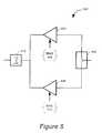
- FIG. 5illustrates an example push-pull PA 500 that can be used in transceiver 300 .
- PA 500comprises an in-phase path and an out-of-phase path, which originate at splitter 502 .
- Splitter 502receives a transmit signal and sends an in-phase signal to amplifier 504 , which is supplied by BIAS 506 .
- Splitter 502also sends an out-of-phase signal to amplifier 508 , supplied by BIAS 510 .
- the out-of-phase signalis 180° out of phase with the in-phase signal.
- After amplification in amplifiers 504 and 508 , respectively, the two signalsare then balanced and combined in combiner 512 .
- the transmitter linearity performancecan be controlled by varying the amplifier biases BIAS 506 and BIAS 510 , respectively.
- the total transmit power levelis the combination of the power levels of the signals in both the in-phase and out-of-phase signal paths.
- PA 500one advantage of PA 500 is that one or the other of amplifiers 504 and 508 can be completely shut off when the total transmit power requirement is low. This can be accomplished, for example, by simply removing the appropriate bias signal. Thus the overall efficiency at low powers is greatly improved.
- the power control circuit 318can be configured to control the impedance of matching circuit 304 in order to reduce the amount of reflected power.
- This capabilityallows the power control circuit 318 further means of lowering the ACPR and ensuring more efficient operation of transceiver 300 .
- the actual impedance presented by antenna 302can change as the communication device is brought near the human head, for example. The change in impedance increases the amount of reflected energy and increases the VSWR. In transceiver 300 , the increased amount of reflected power will also increase ACPR, since there is no isolator to prevent the reflected power from mixing with the transmit signal. To prevent this from occurring, power control circuit 318 can be configured to modify the impedance of matching circuit 304 so as to provide a better match and reduce the amount of reflected power.
- the power control circuit 318can be configured to control the impedance of matching circuit 304 by switching in and out more or less impedance.
- a matching circuit 304typically comprises various inductive and capacitive components in various configurations.
- the power control circuit 318can be configured to switch in and out inductive and/or capacitive components to alter the impedance of matching circuit 304 .
- matching circuit 304can comprise a ferro-electric tunable inductive components and capacitors, the impedance of which can be much more easily controlled to provide dynamic impedance matching for transceiver 300 .
- Systems and methods for controlling the impedance of a ferro-electric tunable matching circuitare described more fully in U.S. patent application Ser. No. 09/927,732, entitled “Tunable Matching Circuit,” filed Aug. 8, 2001, which is fully incorporated herein by reference.
- U.S. patent application Ser. No. 09/927,732entitled “Tunable Matching Circuit,” filed Aug. 8, 2001, which is fully incorporated herein by reference.
Landscapes
- Engineering & Computer Science (AREA)
- Computer Networks & Wireless Communication (AREA)
- Signal Processing (AREA)
- Physics & Mathematics (AREA)
- Electromagnetism (AREA)
- Transmitters (AREA)
Abstract
Description
1. Field of the Invention
The invention relates generally to wireless communication and more particularly to systems and methods for controlling the output power in a wireless communication device.
2. Background
There are several factors that impact the transmit power level in the transmitter of a wireless communication device. Two factors that limit the transmit power level, for example, are: 1) Specific Absorption Rate (SAR) requirements; and 2) Adjacent Channel Power Ratio (ACPR) requirements. SAR is a metric used to evaluate compliance of portable devices with the maximum permissible exposure limits as defined in the FCC guidelines on human exposure to Radio Frequency (RF) emissions. Effectively, the FCC guidelines place a limit on the maximum transmit power of a communication device in order to prevent exposure by users of such devices to excessive levels of RF energy.
ACPR is generally defined as the ratio of the average power in the adjacent frequency channel to the average power in the transmitted frequency channel. In other words, a wireless communication device is configured to transmit over a specific frequency channel at any given time. But due to inherent linearity and other limitations of the components that comprise a communication device transmitter, it is very difficult to prevent the energy transmitted by the device from spreading over into adjacent channels. If too much energy resides in the adjacent channels, then it can interfere with devices operating on those channels. Therefore, many wireless communication standards define limits for ACPR, and even when the applicable standard does not define a limit, ACPR is still a practical limitation.
In order to maintain acceptable SAR and ACPR limits, conventional communication device transmitters typically comprise a power detector, to detect the transmit power level, and an isolator to isolate the transmitter from reflected energy generated at the interface between the transmitter and the device's antenna. For example, in a Frequency Modulation (FM) transmitter, SAR is the limiting issue. Therefore, a power detector can be used to ensure that the output power of the transmitter does not exceed the FCC specified limits. In a transmitter that is implementing a complex modulation scheme, such as Code Division Multiple Access (CDMA) or Time Division Multiple Access (TDMA), on the other hand, there are much more stringent linearity requirements. Thus, ACPR is the limiting issue, although SAR still applies. If the transmitter attempts to produce too much or excessive power is reflected back from the antenna into the transmitter, the linearity and, therefore, the ACPR can be substantially degraded. Accordingly, conventional devices often insert an isolator to block the reflected power and have some means to limit the maximum RF output power if there is a danger of exceeding the transmitter rating before reaching the SAR threshold
While the conventional detector/isolator approach has certain advantages, it also has certain limitations that can substantially impact the performance of a wireless communication device. For example, the impedance of the transmission line that conveys the transmitted power to the antenna is designed to match the impedance of the antenna in order to reduce the amount of reflected energy and increase transmission efficiency. But when the communication device is placed next to the human head, for example, the impedance of the antenna changes due to the proximity with the head. As a result, more power is reflected back toward the transmitter. When this reflected energy reaches the isolator it is dissipated as heat. Therefore, the resulting radiated transmit power is much lower than it otherwise could be, even taking into account the SAR limitation.
Additionally, the isolator introduces extra loss into the transmission path that is typically on the order of 0.5 dB. Therefore, the transmitter must supply an extra 0.5 dB of power in order to compensate for the extra loss. Increasing the power, however, also increases the ACPR, i.e., increases the amount of energy in the adjacent channels. Because ACPR is predominantly a 3rd order product, the resulting increase in ACPR is approximately 3 times the increase in transmit power, or 1.5 dB, which can lead to noncompliance with the ACPR requirements. Thus, as can be seen, the conventional detector/isolator approach can have a substantial negative impact on the performance of a wireless communication device.
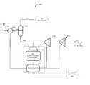
FIG. 1 illustrates an exemplarywireless communication transceiver 100. Such a transceiver can be included in a wireless communication device, thus enabling the device to communicate over awireless communication channel 124 in a wireless communication system.Transceiver 100 actually comprises areceive path 106 and atransmit path 110. Preferably, both paths are interfaced withantenna 102 via aduplexer 108.Duplexer 108 essentially acts as a filter that is configured to shunt incoming RF signals received byantenna 102 to receivepath 106.Duplexer 108 is further configured to send outgoing RF signals fromtransmit path 110 toantenna 102, while providing isolation betweenpaths
The received RF signals are then demodulated and processed so as to extract a baseband information signal in the receive portion of transceiver100 (not shown). Preferably, the baseband information signal is then decoded and processed in a baseband processor (not shown), such as a Mobile Station Modem (MSM). The MSM, or equivalent, is also preferably responsible for generating and encoding baseband information signals that are to be transmitted overcommunication channel 124. The baseband information signals generated by the MSM (not shown) are then modulated with a RF carrier in the transmit portion oftransceiver 100, which generates a RF transmit signal to be transmitted viaantenna 102.
The transmit portion oftransceiver 100 is also preferably configured to set the power level of the RF transmit signal. In general, Power Amplifier (PA)120 in conjunction with Variable Gain Amplifier (VGA)122 generate the required power level as demanded by the MSM. PAs are typically key components in any high frequency RF transmitter design. This is because RF transmitters typically require high output power to compensate for path losses incommunication channel 124 and to ensure an adequate signal strength at the base station associated withchannel 124. Since the base station can be miles away, it can be difficult to achieve adequate receive power at the base station. At the same time, if the signal power at the base station is too high, then it may interfere with reception by the base station of transmit signals from other devices within the communication system. Transmitting at higher power levels also reduces battery operating time. Therefore, while it is important to ensure an adequate transmit power level, it is also important to ensure that the transmit power level is not too high. Thus, power control in a wireless communication device is an important aspect of wireless communication.
In conventional wireless communication systems, power control is often performed in the wireless communication device. For example, the base station can be configured to measure the power level of a received transmit signal and determine if it is too high or too low. The base station can then be configured to transmit commands to the wireless communication device instructing the device to turn its power up or down. CDMA communication systems, for example, use such a power control loop. In a CDMA system, the goal of the base stations is to receive signals from each of the devices with which it is communicating at the same receive power level. In fact, such power equalization at the base station for each of the devices in communication with the base station is a critical aspect of CDMA operation. Thus, power control is a critical component of device operation in a CDMA system, although it is similarly important in many types of wireless communication systems.
For illustrative purposes, a simplified power control loop operation for a CDMA system is described in the following paragraphs in conjunction with the flow chart of FIG.2. The process of FIG. 2 is intended to illustrate the need for power control and the role it plays in wireless communication. It should not, however, be seen as limiting the systems and methods described herein to any particular type of power control, or any particular power control approach. Nor should it be seen as limiting the systems and methods described herein to any particular type of wireless communication system.
Again, in a CDMA system, such as an IS-95 compliant system, the transmit power is controlled in the communication device so that devices communicating with the same base station appear to have the same signal strength at the base station. In each device, the transmit power is variable to compensate for changes in the signal strength as received by the base station. The signal strength at the base station can vary due to changing distances between a communication device and the base station and such factors effectingcommunication channel 124 as multipath fading, varying terrain topology, and varying environmental conditions.
Referring to FIG. 2, the power control loop in a CDMA system, begins by entering an open looppower control sequence 234 instep 202. Once inopen loop sequence 234, the device will estimate an initial transmit power instep 204. For example, the initial estimate can be made using a predetermined loop power equation such as the following equation:
In equation (1), Rx power is the signal strength of a RF signal received from the bases station overcommunication channel 124 byantenna 102. Once this received power level is determined, e.g., via a Received Signal Strength Indication (RSSI) measurement, then it can be used by loop equation (1) to determine the initial transmit power, or Tx power, instep 204. The device will then transmit a signal at this initial power level to the base station instep 206 and wait for an acknowledgement from the base station instep 210. If the device does not receive an acknowledgement instep 212, then it will increase the transmit power instep 214, transmit again instep 216, and again wait for acknowledgement (step210). Typically, a device may need to increase its power 1 or 2 times before receiving the acknowledgement.
The open loop process is a coarse estimate of the required transmit power. Thus a tolerance of +/−9 db is, for example, allowed on the open loop estimate of the required power. Once the device receives an acknowledgement (step212), however, it enters, instep 218, a closedloop power sequence 236 in which the transmit power level estimate is refined. The goal of closed looppower control sequence 236 is to ensure that the power received at the base station is the minimum level of power required for each device with which the base station is communicating.
Once inclosed loop sequence 236, the base station measures the received power-to-interference-ratio (Eb/Io) and compares the measured value to a minimum and a maximum threshold instep 222. If the base station determines that the measured Eb/Io is above the maximum threshold instep 224, then, instep 226, it sends a command to the device to reduce its power. If, on the other hand, the base station determines instep 228 that the Eb/Io is below the minimum threshold, then it sends a command to the device to raise its transmit power level instep 230. Of course, the measured Eb/Io may be between the minimum and maximum thresholds in which case there would be no need for the device to modify its power. In such a situation, the device can be instructed to maintain the same transmit power level instep 232. The measurement (step220) and comparison (222) is preferably repeated periodically, e.g., every 1.25 ms, or 800 times per second. Thus, it can be seen that power control plays an important role in proper operation of a communication device within a wireless communication system.
Referring again to FIG. 1, there are several ways that a device can control the output power intransceiver 100. Because the transmit power may have to be varied over a large range typically in excess of 70 dB, one way to control the output power is by varying the gain ofVGA 122. Further to ensure improved transmitter efficiency at lower power levels, PA bias126 may also be adjusted as required.VGA 122 can be configured to amplify the transmit signal before it is sent toPA 120. Howmuch VGA 122 amplifies the transmit signal can be controlled via a TXPOWER CONTROL signal 128, which can be generated by an MSM (not shown) or some other baseband control circuit (not shown).
Proper control of the transmit power level, as explained above, can be critical for efficient operation of a wireless communication device in a wireless communication system. There are other limits, however, on the transmit power level intransceiver 100. For example, as explained above, SAR limitations may restrict the transmit power level regardless of what the power control loop operation may dictate. To ensure that the SAR limitations are not exceeded, conventional wireless communication devices typically employ some sort ofpower detector 114. Intransceiver 100,power detector 114 comprises adiode 118. Theoutput 130 ofdetector 114 is then sent to a MSM (not shown) or some other baseband control circuit (not shown).
The analog voltage generated by thedetector 114 represents the generated transmit power level and can be converted to a digital number, by means of an analog-to-digital converter for example, such that the MSM (not shown) can adjust the gain ofVGA 122 accordingly to meet the desired transmit power level. Notably, however, such a power detection scheme does not take into account reflected power that is dissipated inisolator 112.Isolator 112 is included because the reflected power can have an adverse effect, e.g., increased ACPR especially at high transmit power levels, if it is allowed to interact with the transmit signal being generated byPA 120.
Reflected power occurs because of mismatches in the impedance between thetransmission line 132 conveying the transmit signal andantenna 102. The amount of reflected power is determined by the reflection coefficient, which is a measure of the mismatch in impedance betweenantenna 102 andtransmission line 132. To lower the reflection coefficient, and thereby reduce the amount of reflected power, conventional devices typically include matchingcircuit 104. The purpose of matchingcircuit 104 is to match the impedance oftransmission line 132 with that ofantenna 102. In practice, however, it is very difficult to achieve a perfect match. Therefore, some of the transmit power is reflected back towardPA 120. The reflected power generates a standing wave ontransmission line 132 from the interaction between the forward and reflected signals. Voltage Standing Wave Ratio (VSWR) is a metric used to determine how much of the transmitted power is making it out atantenna 102. VSWR can be defined by the following equation:
In equation (2), Vfwd is a measure of the voltage level of the transmit signal ontransmission line 132 and Vref is a measure of the voltage level of the reflected signal. Ifimpedance matching circuit 104 provides a perfect match, then the ratio is 1:1 and maximum power will be delivered toantenna 102. Any deviation from this condition, i.e., a VSWR greater than 1:1, and less than maximum power is delivered toantenna 102.
If it were not forisolator 112, the reflected power would travel back towardPA 120, reflect again, and travel back towardantenna 102. Therefore, at least some portion of the reflected power would eventually get out atantenna 102. Thus, a transceiver can be designed for a VSWR of approximately 2:1 and still have sufficient performance. But intransceiver 102, the reflected power is actually dissipated inisolator 112 as heat. Thus, any deviation from a VSWR of 1:1 results in wasted transmit power and reduced talk time. Butdetector 114 does not take into account the effect ofisolator 112 and, as a result,transceiver 100 can actually be operating well below SAR limits when the device is limiting the PA output due to the measurements fromdetector 114.
For example, it is not uncommon for the VSWR to degrade from 2:1 to approximately 3:1 when a wireless communication device is placed next to a human head during operation. A VSWR of 3:1, however, means that 25% of the transmit power is reflected back into the device, where it is dissipated as heat inisolator 112. Because this power is wasted, the power level is much lower than expected. This not only results in inefficient operation oftransceiver 100, but can actually cause the device to lose its connection with the base station. Even ifdetector 114 is not causing the transmit power level to be limited,PA 120 must operate at excessive power levels in order to compensate for the transmit power wasted inisolator 112, which not only reduces battery capacity but can also raise ACPR.
As mentioned above,isolator 112 also typically adds approximately 0.5 dB of loss to the transmission path, which requiresPA 120 to increase the transmit power level to compensate. Not only does this result in inefficient operation ofPA 120 and reduces battery life among other things, but it also causes the ACPR to increase. Because ACPR is a 3rd order product, a 0.5 dB increase in transmit power will result in approximately a 1.5 dB increase in ACPR, which may cause excessive interference in the adjacent channel.
In view of the above discussion, it can be seen that the use ofdetector 114 andisolator 112 can have a substantial negative impact on the performance oftransceiver 100.
Thus, it is an objective of the invention to eliminate the need for an isolator in the transmitter of a wireless communication device. It is a further objective to provide dynamic control of the transmit power level in the transmitter in order to maintain maximum output power, while still meeting such limitations as SAR and ACPR. In one aspect of the invention, the systems and methods for controlling output power in a communication device use a power control circuit to sense both the forward and reflected power levels in the transmission path between the transmitter and the antenna. The power control circuit is then configured to control the transmit power level of the transmitter based on the power levels that it senses.
For example, in one particular implementation the transmitter power level can be optimally controlled by adjusting a Power Amplifier (PA) drive signal in accordance with inputs from a MSM, such as a demanded transmit power input, and by forward/reverse powers detected by the power control circuit. For example in an extreme case where forward and reflected powers are identical (100% power reflection), this invention would reduce drive power to the PA to a very low level and avoid the condition of dissipating excess power as heat. Further the power control system would adjust the PA bias to the most appropriate point for a given output level. For higher power levels where high linearity is required the bias would be increased. For lower power levels the bias point would be decreased, but not to a point where ACPR is impacted.
In another aspect of the invention, the power control circuit may also adjust an impedance of an impedance matching circuit based at least in part on the reflected power level sensed by the bi-directional coupler detector.
These embodiments as well as other features, advantages, and embodiments are described below in conjunction with the following drawings.
Preferred embodiments of the present inventions taught herein are illustrated by way of example, and not by way of limitation, in the figures of the accompanying drawings, in which:
FIG. 1 is a logical block diagram illustrating an exemplary wireless communication transceiver;
FIG. 2 is a flow chart illustrating an exemplary power control loop process for controlling the transmit power level in the wireless transceiver of FIG. 1;
FIG. 3 is a logical block diagram illustrating an example embodiment of a wireless communication transceiver in accordance with the invention;
FIG. 4 is flow chart illustrating an example embodiment of a process for controlling the transmit power level in the wireless transceiver of FIG. 3 in accordance with the invention; and
FIG. 5 is a logical block diagram illustrating an exemplary power amplifier for use in the transceiver of FIG.3.
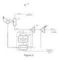
FIG. 3 illustrates an example embodiment of atransceiver 300 designed in accordance with the systems and methods described herein. As can be seen,transceiver 300 can comprise anantenna 302, matchingcircuit 304,duplexer 308, receivepath 310, transmitpath 328,PA 312, andVGA 314, which operate in substantially the same manner as described in relation to the similar components oftransceiver 100. Instead ofisolator 112, however,transceiver 300 includespower control circuit 318, which preferably comprisesbi-directional coupler detector 316 and aprocessor 320.Processor 320 can be a DSP, microcontroller, microprocessor, or any other type of controller capable of implementing the systems and methods as described herein.Further Processor 320 can be integrated within the MSM.
Preferably,processor 320 is configured to control the transmit power level in the same ways described above. Thus,processor 320 is preferably interfaced withVGA 314 in such a manner as to be able to modify the gain of theVGA 314, which is preferably initially set in accordance with instruction from the MSM (not shown). It will be appreciated thatpower control circuit 318 may not include aprocessor 320. In that case,power control circuit 318 would be coupled to some other suitable controller for performing the functions described herein with reference toprocessor 320. A MSM (not shown), for example, could be configured to perform these functions.
By eliminatingisolator 112, significant savings can be recognized in the construction oftransceiver 300 including savings in cost, component count, and board area. Moreover,power control circuit 318 helps to provide greater control over the transmit power level, which results in better performance, reduced power consumption, and increased battery life.
FIG. 4 is a flow chart illustrating an example method wherebypower control circuit 318 can controlVGA 314 andPA 312 in order to control the transmit power level in a transceiver such astransceiver 300. First, instep 402, thepower control circuit 318 can receive a control signal instructing that the gain ofVGA 314 be set to a predetermined level. For example,power control circuit 318 can be instructed to set the gain such that the transmit power level is equal to an initial power level as determined using equation (1) or an equivalent equation. Alternatively, the initial gain can be set by the MSM (not shown) or other baseband control circuit (not shown).
Next, instep 404,bi-directional coupler detector 316 senses the forward and reverse power levels ontransmission line 324. Then instep 406,power control circuit 318 accurately determines the amount of transmit signalpower reaching antenna 302 and actually being radiated by comparing the forward and reverse power levels. If the powerlevel reaching antenna 302 and being radiated exceeds the SAR limitations as determined instep 408, then instep 410 thepower control circuit 318 can decrease the transmit power level by varying the gain ofVGA 314, for example. Alternatively,power control circuit 318 can be interfaced with the MSM (not shown), or other baseband control circuit (not shown), configured to control the gain. Thus, after making the determination instep 408,power control circuit 318 can cause the MSM (not shown) or baseband control circuit (not shown) to reduce the transmit power level.
Instep 408,bi-directional coupler detector 316 determines if the reflected power level is excessive enough to raise the ACPR to an unacceptable level. If it is, then the process again goes to step410 and the transmit power level is reduced.
A push-pull PA design can be used forPA 312 to further reduce ACPR and enhance power conservation withintransceiver 300. FIG. 5 illustrates an example push-pull PA 500 that can be used intransceiver 300.PA 500 comprises an in-phase path and an out-of-phase path, which originate atsplitter 502.Splitter 502 receives a transmit signal and sends an in-phase signal toamplifier 504, which is supplied by BIAS506.Splitter 502 also sends an out-of-phase signal toamplifier 508, supplied byBIAS 510. The out-of-phase signal is 180° out of phase with the in-phase signal. After amplification inamplifiers combiner 512.
The transmitter linearity performance can be controlled by varying the amplifier biases BIAS506 andBIAS 510, respectively. The total transmit power level is the combination of the power levels of the signals in both the in-phase and out-of-phase signal paths. Thus, one advantage ofPA 500 is that one or the other ofamplifiers
In another embodiment, thepower control circuit 318 can be configured to control the impedance of matchingcircuit 304 in order to reduce the amount of reflected power. This capability allows thepower control circuit 318 further means of lowering the ACPR and ensuring more efficient operation oftransceiver 300. Thus, for example, the actual impedance presented byantenna 302 can change as the communication device is brought near the human head, for example. The change in impedance increases the amount of reflected energy and increases the VSWR. Intransceiver 300, the increased amount of reflected power will also increase ACPR, since there is no isolator to prevent the reflected power from mixing with the transmit signal. To prevent this from occurring,power control circuit 318 can be configured to modify the impedance of matchingcircuit 304 so as to provide a better match and reduce the amount of reflected power.
In one implementation, thepower control circuit 318 can be configured to control the impedance of matchingcircuit 304 by switching in and out more or less impedance. Amatching circuit 304 typically comprises various inductive and capacitive components in various configurations. Thus, for example, thepower control circuit 318 can be configured to switch in and out inductive and/or capacitive components to alter the impedance of matchingcircuit 304.
Impedance matching using fixed valued inductive components and capacitors is difficult to achieve and highly application specific. Therefore, only a limited amount of impedance control can practically be achieved in the manner just described. In another implementation, however, matchingcircuit 304 can comprise a ferro-electric tunable inductive components and capacitors, the impedance of which can be much more easily controlled to provide dynamic impedance matching fortransceiver 300. Systems and methods for controlling the impedance of a ferro-electric tunable matching circuit are described more fully in U.S. patent application Ser. No. 09/927,732, entitled “Tunable Matching Circuit,” filed Aug. 8, 2001, which is fully incorporated herein by reference. Thus, by using the systems and methods described in U.S. patent application Ser. No. 09/927,732, the advantages of the systems and methods described herein are even further enhanced and extended.
It should be noted that the above examples are provide for illustration only and are not intended to limit the invention to any particular type of transceiver architecture or to any particular type of wireless communication device. Moreover, the systems and methods described herein do not necessarily need to be implemented in a transceiver, they can, for example, be implemented in a device that solely comprise a transmitter incorporating apower control circuit 318. Thus, while embodiments and implementations of the invention have been shown and described, it should be apparent that many more embodiments and implementations are within the scope of the invention. Accordingly, the invention is not to be restricted, except in light of the claims and their equivalents.
Claims (47)
1. A power control circuit comprising a bi-directional coupler detector configured to couple the power control circuit with a transmission line and to sense a forward power level and a reflected power level in the transmission line, the power control circuit configured to:
determine the amount of transmit signal power being radiated by an antenna interfaced with the transmission line;
determine if the radiated signal power exceeds a first threshold;
if the radiated signal power does exceed the first threshold, then decrease a transmit signal power level;
determine if the radiated signal power exceeds a second threshold; and
if the radiated signal power does exceed the second threshold, then decrease the transmit signal power level.
2. The power control circuit ofclaim 1 , configured to decrease the transmit signal power level by controlling the amplification of a power amplifier.
3. The power control circuit ofclaim 1 , configured to decrease the transmit signal power level by controlling the amplification of an in-phase transmission path and an out-of-phase transmission path of a power amplifier.
4. The power control circuit ofclaim 3 , wherein decreasing the transmit signal power level can include turning off one of the in-phase and out-of-phase transmission paths.
5. The power control circuit ofclaim 1 , configured to decrease the transmit signal power level by controlling a variable gain amplifier.
6. The power control circuit ofclaim 5 , wherein controlling the variable gain amplifier comprises varying a gain of the variable gain amplifier.
7. The power control circuit ofclaim 1 , wherein the first threshold is based on SAR requirements.
8. The power control circuit ofclaim 1 , wherein the second threshold is based on ACPR requirements.
9. The power control circuit ofclaim 1 , wherein determining the radiated signal power comprises comparing the sensed forward and reflected 1 power levels.
10. The power control circuit ofclaim 1 , wherein the power control circuit is configured to operate at low transmit signal power levels used in CDMA systems.
11. A wireless communication device, comprising:
a power amplifier configured to amplify a power level of a transmit signal to a required transmit power level;
a transmission line coupled with the power amplifier, the transmission line configured to convey the amplified transmit signal; and
a power control circuit including a bi-directional coupler detector coupled with the transmission line, the bi-directional coupler detector configured to sense a forward power level and a reflected power level in the transmission line, the power control circuit configured to:
determine the amount of transmit signal power being radiated by an antenna interfaced with the transmission line;
determine if the radiated signal power exceeds a first threshold;
if the radiated signal power does exceed the first threshold, then decrease a transmit signal power level;
determine if the radiated signal power exceeds a second threshold; and
if the radiated signal power does exceed the second threshold, then decrease the transmit signal power level.
12. The wireless communication device ofclaim 11 , further comprising an antenna coupled with the transmission line, wherein the transmission line is configured to convey the amplified transmit signal from the power amplifier to the antenna, and wherein the antenna is configured to transmit the amplified transmit signal.
13. The wireless communication device ofclaim 12 , further comprising an impedance matching circuit configured to match an impedance of the transmission line to an impedance of the antenna in order to reduce a magnitude of the reflected power level.
14. The wireless communication device ofclaim 11 , wherein the power control circuit is configured to decrease the transmit signal power level by controlling the amplification provided by the power amplifier.
15. The wireless communication device ofclaim 14 , wherein the power amplifier comprises an in-phase transmission path and an-out-of phase transmission path, and wherein the power control circuit is configured to decrease the transmit signal power level by controlling the amplification provided by the in-phase transmission path and the out-of-phase transmission path.
16. The wireless communication device ofclaim 15 , wherein decreasing the transmit signal power level can include turning off one of the in-phase and out-of-phase transmission paths.
17. The wireless communication device ofclaim 11 , further comprising a variable gain amplifier coupled with the power amplifier, the variable gain amplifier configured to generate the transmit signal, wherein the power control circuit is configured to decrease the transmit signal power level by controlling the variable gain amplifier.
18. The wireless communication device ofclaim 17 , wherein controlling the variable gain amplifier comprises varying a gain of the variable gain amplifier.
19. The wireless communication device ofclaim 11 , wherein the first threshold is based on SAR requirements.
20. The wireless communication device ofclaim 11 , wherein the second threshold is based on ACPR requirements.
21. The wireless communication device ofclaim 11 , wherein determining the radiated signal power comprises comparing the sensed forward and reflected 1 power levels.
22. The wireless communication device ofclaim 11 , wherein the power control circuit is configured to operate at low transmit signal power levels used in CDMA systems.
23. A wireless communication device, comprising:
a transmission line configured to convey a transmit signal;
an impedance matching circuit coupled with the transmission line, the impedance matching circuit configured to match the impedance of the transmission line with a required output impedance; and
a power control circuit including a bi-directional coupler detector coupled with the transmission line, the bi-directional coupler detector configured to sense a reflected power level in the transmission line, the power control circuit configured to:
determine the amount of transmit signal power being radiated by an antenna interfaced with the transmission line;
determine if the radiated signal power exceeds a first threshold;
if the radiated signal power does exceed the first threshold, then adjust the impedance of the impedance matching circuit;
determine if the radiated signal power exceeds a second threshold; and
if the radiated signal power does exceed the second threshold, then adjust the impedance of the impedance matching circuit.
24. The wireless communication device ofclaim 23 , wherein the impedance matching circuit comprises a ferro-electric tunable matching circuit, and wherein the power control circuit is configured to adjust the impedance of the impedance matching circuit by tuning the ferro-electric tunable matching circuit.
25. The wireless communication device ofclaim 23 , further comprising a power amplifier coupled with the transmission line, the power amplifier configured to amplify a signal power level of the transmit signal to a required transmit signal power level and to drive the amplified transmit signal down the transmission line.
26. The wireless communication device ofclaim 25 , wherein the power control circuit is configured to adjust the required transmit signal power level by controlling the amplification provided by the power amplifier.
27. The wireless communication device ofclaim 26 , wherein the power amplifier comprises an in-phase transmission path and an-out-of phase transmission path, and wherein the power control circuit is configured to adjust the required transmit signal power level by controlling the amplification provided by the in-phase transmission path and the out-of-phase transmission path.
28. The wireless communication device ofclaim 27 , wherein adjusting the required transmit signal power level can include turning off one of the in-phase and out-of-phase transmission paths.
29. The wireless communication device ofclaim 25 , further comprising a variable gain amplifier coupled with the power amplifier, the variable gain amplifier configured to generate the transmit signal, wherein the bi-directional coupler detector is configured to adjust the required transmit signal power level by controlling the variable gain amplifier.
30. The wireless communication device ofclaim 29 , wherein controlling the variable gain amplifier comprises varying a gain of the variable gain amplifier.
31. The wireless communication device ofclaim 23 , wherein the bi-directional coupler detector is further configured to sense a forward power level in the transmission line, and wherein the power control circuit is configured to adjust a transmit power level based at least in part on the forward and reflected power levels sensed by the bi-directional coupler detector.
32. The wireless communication device ofclaim 23 , further comprising an antenna coupled with the transmission line, the antenna configured to transmit the amplified transmit signal, and wherein the matching circuit is configured to match the impedance of the transmission line to the impedance of the antenna.
33. The wireless communication device ofclaim 23 , wherein the first threshold is based on SAR requirements.
34. The wireless communication device ofclaim 23 , wherein the second threshold is based on ACPR requirements.
35. The wireless communication device ofclaim 23 , wherein determining the radiated signal power comprises comparing a sensed forward and reflected power levels.
36. The wireless communication device ofclaim 23 , wherein the power control circuit is configured to operate at low transmit signal power levels used in CDMA systems.
37. A method of controlling output power in a wireless communication device, comprising:
sensing a forward power level of a transmit signal as the transmit signal travels from a power amplifier to an antenna of the wireless communication device;
sensing a power level of a portion of the transmit signal that is reflected back toward the power amplifier;
determine the amount of transmit signal power being radiated by an antenna interfaced with the transmission line;
determine if the radiated signal power exceeds a first threshold;
if the radiated signal power does exceed the first threshold, then decrease a transmit signal power level;
determine if the radiated signal power exceeds a second threshold; and
if the radiated signal power does exceed the second threshold, then decrease the transmit signal power level.
38. The method ofclaim 37 , further comprising adjusting an impedance of an impedance matching circuit based at least in part on the sensed reflected power level.
39. The method ofclaim 37 , wherein decreasing the transmit signal power level-comprises adjusting a bias voltage of the power amplifier.
40. The method ofclaim 37 , wherein decreasing the transmit signal power level comprises adjusting a gain of a variable gain amplifier.
41. The method ofclaim 37 , wherein the first threshold is based on SAR requirements.
42. The method ofclaim 37 , wherein the second threshold is based on ACPR requirements.
43. The method ofclaim 37 , wherein determining the radiated signal power comprises comparing the sensed forward and reflected power levels.
44. A wireless communication device configured to communicate using low power level CDMA signals, comprising a power control circuit including a bi-directional coupler detector coupled with the transmission line, the bi-directional coupler detector configured to sense a forward power level and a reflected power level in the transmission line, the power control circuit configured to:
determine the amount of transmit signal power being radiated by an antenna interfaced with the transmission line;
determine if the radiated signal power exceeds a first threshold;
if the radiated signal power does exceed the first threshold, then decrease a transmit signal power level;
determine if the radiated signal power exceeds a second threshold; and
if the radiated signal power does exceed the second threshold, then decrease the transmit signal power level.
45. The wireless communication device ofclaim 44 , wherein the first threshold is based on SAR requirements.
46. The wireless communication device ofclaim 44 , wherein the second threshold is based on ACPR requirements.
47. The wireless communication device ofclaim 44 , wherein determining the radiated signal power comprises comparing the sensed forward and reflected power levels.
Priority Applications (2)
| Application Number | Priority Date | Filing Date | Title |
|---|---|---|---|
| US10/035,596US6710651B2 (en) | 2001-10-22 | 2001-10-22 | Systems and methods for controlling output power in a communication device |
| US10/806,763US7071776B2 (en) | 2001-10-22 | 2004-03-22 | Systems and methods for controlling output power in a communication device |
Applications Claiming Priority (1)
| Application Number | Priority Date | Filing Date | Title |
|---|---|---|---|
| US10/035,596US6710651B2 (en) | 2001-10-22 | 2001-10-22 | Systems and methods for controlling output power in a communication device |
Related Child Applications (1)
| Application Number | Title | Priority Date | Filing Date |
|---|---|---|---|
| US10/806,763Continuation-In-PartUS7071776B2 (en) | 2001-10-22 | 2004-03-22 | Systems and methods for controlling output power in a communication device |
Publications (2)
| Publication Number | Publication Date |
|---|---|
| US20030076168A1 US20030076168A1 (en) | 2003-04-24 |
| US6710651B2true US6710651B2 (en) | 2004-03-23 |
Family
ID=21883644
Family Applications (1)
| Application Number | Title | Priority Date | Filing Date |
|---|---|---|---|
| US10/035,596Expired - Fee RelatedUS6710651B2 (en) | 2001-10-22 | 2001-10-22 | Systems and methods for controlling output power in a communication device |
Country Status (1)
| Country | Link |
|---|---|
| US (1) | US6710651B2 (en) |
Cited By (102)
| Publication number | Priority date | Publication date | Assignee | Title |
|---|---|---|---|---|
| US20030060227A1 (en)* | 2001-09-27 | 2003-03-27 | Sekine Shu-Ichi | Portable type radio equipment |
| US20030114182A1 (en)* | 2001-12-19 | 2003-06-19 | Chan Paul L. | Adaptive power amplifier |
| US20030151697A1 (en)* | 2002-02-08 | 2003-08-14 | Samsung Electronics Co., Ltd. | Apparatus for transmitting video signal, apparatus for receiving video signal, transceiver therefor, and method for determining channel |
| US20040121799A1 (en)* | 2002-12-24 | 2004-06-24 | Tzeng-Chih Chiou | Mobile phone for informing users of radiation power levels |
| US20040166887A1 (en)* | 2003-02-24 | 2004-08-26 | Rajiv Laroia | Pilot signals for use in multi-sector cells |
| US20050075123A1 (en)* | 2003-10-06 | 2005-04-07 | Research In Motion Limited | System and method of controlling transmit power for mobile wireless devices with multi-mode operation of antenna |
| US20050124304A1 (en)* | 2003-12-09 | 2005-06-09 | Oded Bendov | TV & FM transmitting system early warning monitoring |
| US20050181784A1 (en)* | 2004-02-16 | 2005-08-18 | Benq Corporation | System and method for calibrating a transceiver |
| US20060092881A1 (en)* | 2004-10-14 | 2006-05-04 | Rajiv Laroia | Methods and apparatus for determining, communicating and using information which can be used for interference control purposes |
| US20060120330A1 (en)* | 2004-12-06 | 2006-06-08 | Pantech Co., Ltd. | Method of converting communication channel in mobile communication terminal |
| US20060154687A1 (en)* | 2001-09-28 | 2006-07-13 | Agere Systems Incorporated | Proximity regulation system for use with a portable cell phone and a method of operation thereof |
| US20060160501A1 (en)* | 2000-07-20 | 2006-07-20 | Greg Mendolia | Tunable microwave devices with auto-adjusting matching circuit |
| US20060166692A1 (en)* | 2005-01-24 | 2006-07-27 | Intel Corporation | Mitigating interference to nearby radio systems based on characterization of adjacent channels |
| US20060183431A1 (en)* | 2005-02-17 | 2006-08-17 | Henry Chang | Mobile station traffic state antenna tuning systems and methods |
| US20060183443A1 (en)* | 2005-02-17 | 2006-08-17 | Henry Chang | Mobile station access and idle state antenna tuning systems and methods |
| US20060183442A1 (en)* | 2005-02-17 | 2006-08-17 | Henry Chang | Mobile station acquisition state antenna tuning systems and methods |
| US20070042725A1 (en)* | 2005-08-22 | 2007-02-22 | Gregory Poilasne | Systems and methods for tuning an antenna configuration in a mobile communication device |
| WO2005112593A3 (en)* | 2004-05-17 | 2007-04-05 | Cellular3G Inc | Body-worn radio signal transmitting apparatus |
| US20070111681A1 (en)* | 2005-11-14 | 2007-05-17 | Alberth William P Jr | Transmit power allocation in wireless communication devices |
| US20070140168A1 (en)* | 2005-10-14 | 2007-06-21 | Rajiv Laroia | Methods and apparatus for determining, communicating and using information which can be used for interference control |
| US20070142014A1 (en)* | 2005-12-19 | 2007-06-21 | Sony Ericsson Mobile Communications Ab | Devices, methods, and computer program products for controlling power transfer to an antenna in a wireless mobile terminal |
| US20070149131A1 (en)* | 2005-12-22 | 2007-06-28 | Junyi Li | Methods and apparatus related to custom control channel reporting formats |
| US20070149129A1 (en)* | 2005-12-22 | 2007-06-28 | Arnab Das | Methods and apparatus for communicating transmission backlog information |
| US20070149137A1 (en)* | 2005-12-22 | 2007-06-28 | Tom Richardson | Methods and apparatus for communicating control information |
| US20070149194A1 (en)* | 2005-12-22 | 2007-06-28 | Arnab Das | Communications device control information reporting related methods and apparatus |
| US20070149228A1 (en)* | 2005-12-22 | 2007-06-28 | Arnab Das | Methods and apparatus for flexible reporting of control information |
| US20070149128A1 (en)* | 2005-12-22 | 2007-06-28 | Arnab Das | Methods and apparatus for reporting and/or using control information |
| US20070149126A1 (en)* | 2003-02-24 | 2007-06-28 | Sunddeep Rangan | Methods and apparatus for generating, communicating, and/or using information relating to self-noise |
| US20070149132A1 (en)* | 2005-12-22 | 2007-06-28 | Junyl Li | Methods and apparatus related to selecting control channel reporting formats |
| US20070149138A1 (en)* | 2005-12-22 | 2007-06-28 | Arnab Das | Methods and apparatus for communicating information utilizing a plurality of dictionaries |
| US20070149238A1 (en)* | 2005-12-22 | 2007-06-28 | Amab Das | Methods and apparatus for communicating and/or using transmission power information |
| US20070159969A1 (en)* | 2005-12-22 | 2007-07-12 | Arnab Das | Methods and apparatus for communicating transmission backlog information |
| US20070168326A1 (en)* | 2003-02-24 | 2007-07-19 | Arnab Das | Efficient reporting of information in a wireless communication system |
| US20070197180A1 (en)* | 2006-01-14 | 2007-08-23 | Mckinzie William E Iii | Adaptive impedance matching module (AIMM) control architectures |
| US20070200766A1 (en)* | 2006-01-14 | 2007-08-30 | Mckinzie William E Iii | Adaptively tunable antennas and method of operation therefore |
| US20070213087A1 (en)* | 2003-02-24 | 2007-09-13 | Qualcomm Incorporated | Method of transmitting pilot tones in a multi-sector cell, including null pilot tones, for generating channel quality indicators |
| US20070243882A1 (en)* | 2006-04-12 | 2007-10-18 | Qualcomm Incorporated | Method and apparatus for locating a wireless local area network associated with a wireless wide area network |
| US20070249287A1 (en)* | 2005-12-22 | 2007-10-25 | Arnab Das | Methods and apparatus for selecting between a plurality of dictionaries |
| US20070253385A1 (en)* | 2005-10-14 | 2007-11-01 | Junyi Li | Methods and apparatus for controlling a base stations's transmission power |
| US20070285326A1 (en)* | 2006-01-14 | 2007-12-13 | Mckinzie William E | Adaptively tunable antennas incorporating an external probe to monitor radiated power |
| US20070298835A1 (en)* | 2006-06-27 | 2007-12-27 | Motorola, Inc. | Method and system for managing communications for a multi-mode communications device |
| US20080106349A1 (en)* | 2006-11-08 | 2008-05-08 | Mckinzie William E | Adaptive impedance matching apparatus, system and method |
| US20080122553A1 (en)* | 2006-11-08 | 2008-05-29 | Mckinzie William E | Adaptive impedance matching module |
| US20080130728A1 (en)* | 2006-11-30 | 2008-06-05 | Motorola, Inc. | Monitoring and control of transmit power in a multi-modem wireless communication device |
| US20080130727A1 (en)* | 2006-11-30 | 2008-06-05 | Motorola, Inc. | Monitoring multiple modem transmission in a communication device |
| US20080136714A1 (en)* | 2006-12-12 | 2008-06-12 | Daniel Boire | Antenna tuner with zero volts impedance fold back |
| US20080146268A1 (en)* | 2006-12-14 | 2008-06-19 | Motorola, Inc. | Multimodal phone data session management enhancement that alleviates dual transmission problems |
| US20080261544A1 (en)* | 2007-04-23 | 2008-10-23 | Guillaume Blin | Techniques for improved adaptive impedance matching |
| US20090039976A1 (en)* | 2006-11-08 | 2009-02-12 | Mckinzie Iii William E | Adaptive impedance matching apparatus,system and method with improved dynamic range |
| US20090046030A1 (en)* | 2007-06-08 | 2009-02-19 | Arizona Board Of Regents For And On Behalf Of Arizona State University | Automatic Antenna Tuning Unit for Software-Defined and Cognitive Radio |
| US20090275355A1 (en)* | 2008-04-30 | 2009-11-05 | Motorola, Inc. | Method and apparatus for controlling power among modems in a multi-mode mobile communication device |
| US20090280819A1 (en)* | 2008-05-07 | 2009-11-12 | At&T Mobility Ii Llc | Femto cell signaling gating |
| US20090280853A1 (en)* | 2008-05-07 | 2009-11-12 | At&T Mobility Ii Llc | Signaling-triggered power adjustment in a femto cell |
| US20090286512A1 (en)* | 2008-05-13 | 2009-11-19 | At&T Mobility Ii Llc | Exchange of access control lists to manage femto cell coverage |
| US7623857B1 (en)* | 2005-10-21 | 2009-11-24 | At&T Intellectual Property I, L.P. | Intelligent pico-cell for transport of wireless device communications over wireline networks |
| US20090298470A1 (en)* | 2008-05-13 | 2009-12-03 | At&T Mobility Ii Llc | Administration of access lists for femtocell service |
| US20100029231A1 (en)* | 2008-07-30 | 2010-02-04 | Demian Martin | Look -Up Table for Control of Power Output From FM Transmitters |
| US20100027469A1 (en)* | 2008-06-12 | 2010-02-04 | At&T Mobility Ii Llc | Point of sales and customer support for femtocell service and equipment |
| US20100090760A1 (en)* | 2008-10-14 | 2010-04-15 | Paratek Microwave, Inc. | Low-distortion voltage variable capacitor assemblies |
| US20100279751A1 (en)* | 2009-05-01 | 2010-11-04 | Sierra Wireless, Inc. | Method and apparatus for controlling radiation characteristics of transmitter of wireless device in correspondence with transmitter orientation |
| US20100279630A1 (en)* | 2009-04-29 | 2010-11-04 | Lockheed Martin Corporation | Radio frequency power monitor |
| US20110053524A1 (en)* | 2009-08-25 | 2011-03-03 | Paratek Microwave, Inc. | Method and apparatus for calibrating a communication device |
| US20110063042A1 (en)* | 2000-07-20 | 2011-03-17 | Paratek Microwave, Inc. | Tunable microwave devices with auto-adjusting matching circuit |
| US20110086630A1 (en)* | 2009-10-10 | 2011-04-14 | Paratek Microwave, Inc. | Method and apparatus for managing operations of a communication device |
| US20110093913A1 (en)* | 2009-10-15 | 2011-04-21 | At&T Intellectual Property I, L.P. | Management of access to service in an access point |
| US7991363B2 (en) | 2007-11-14 | 2011-08-02 | Paratek Microwave, Inc. | Tuning matching circuits for transmitter and receiver bands as a function of transmitter metrics |
| US8072285B2 (en) | 2008-09-24 | 2011-12-06 | Paratek Microwave, Inc. | Methods for tuning an adaptive impedance matching network with a look-up table |
| US20120142393A1 (en)* | 2010-12-06 | 2012-06-07 | Samsung Electronics Co., Ltd. | Method and apparatus for controlling transmission power in mobile terminal |
| US8213886B2 (en) | 2007-05-07 | 2012-07-03 | Paratek Microwave, Inc. | Hybrid techniques for antenna retuning utilizing transmit and receive power information |
| US20120169335A1 (en)* | 2009-09-17 | 2012-07-05 | Koninklijke Philips Electronics N.V. | Multi-element transmit rf chain with local automatic tune and match device |
| US8326296B1 (en) | 2006-07-12 | 2012-12-04 | At&T Intellectual Property I, L.P. | Pico-cell extension for cellular network |
| US8432234B2 (en) | 2010-11-08 | 2013-04-30 | Research In Motion Rf, Inc. | Method and apparatus for tuning antennas in a communication device |
| US8503938B2 (en) | 2004-10-14 | 2013-08-06 | Qualcomm Incorporated | Methods and apparatus for determining, communicating and using information including loading factors which can be used for interference control purposes |
| US8514692B2 (en) | 2003-02-24 | 2013-08-20 | Qualcomm Incorporated | Methods and apparatus for determining, communicating and using information which can be used for interference control purposes |
| US8594584B2 (en) | 2011-05-16 | 2013-11-26 | Blackberry Limited | Method and apparatus for tuning a communication device |
| US8626083B2 (en) | 2011-05-16 | 2014-01-07 | Blackberry Limited | Method and apparatus for tuning a communication device |
| US8655286B2 (en) | 2011-02-25 | 2014-02-18 | Blackberry Limited | Method and apparatus for tuning a communication device |
| US8712340B2 (en) | 2011-02-18 | 2014-04-29 | Blackberry Limited | Method and apparatus for radio antenna frequency tuning |
| USRE44998E1 (en) | 2000-07-20 | 2014-07-08 | Blackberry Limited | Optimized thin film capacitors |
| US8803631B2 (en) | 2010-03-22 | 2014-08-12 | Blackberry Limited | Method and apparatus for adapting a variable impedance network |
| US8860526B2 (en) | 2010-04-20 | 2014-10-14 | Blackberry Limited | Method and apparatus for managing interference in a communication device |
| US20140370830A1 (en)* | 2013-06-13 | 2014-12-18 | Research In Motion Limited | Device dynamic total rf power compensation |
| US8948889B2 (en) | 2012-06-01 | 2015-02-03 | Blackberry Limited | Methods and apparatus for tuning circuit components of a communication device |
| US9119220B2 (en) | 2005-12-22 | 2015-08-25 | Qualcomm Incorporated | Methods and apparatus for communicating backlog related information |
| US9246223B2 (en) | 2012-07-17 | 2016-01-26 | Blackberry Limited | Antenna tuning for multiband operation |
| US20160126619A1 (en)* | 2014-10-30 | 2016-05-05 | Mediatek Singapore Pte. Ltd. | Wireless communication unit, integrated circuit and method for antenna tuning |
| US9338767B2 (en) | 2005-12-22 | 2016-05-10 | Qualcomm Incorporated | Methods and apparatus of implementing and/or using a dedicated control channel |
| US9350405B2 (en) | 2012-07-19 | 2016-05-24 | Blackberry Limited | Method and apparatus for antenna tuning and power consumption management in a communication device |
| US9362891B2 (en) | 2012-07-26 | 2016-06-07 | Blackberry Limited | Methods and apparatus for tuning a communication device |
| US9374113B2 (en) | 2012-12-21 | 2016-06-21 | Blackberry Limited | Method and apparatus for adjusting the timing of radio antenna tuning |
| US9406444B2 (en) | 2005-11-14 | 2016-08-02 | Blackberry Limited | Thin film capacitors |
| US9413066B2 (en) | 2012-07-19 | 2016-08-09 | Blackberry Limited | Method and apparatus for beam forming and antenna tuning in a communication device |
| US9769826B2 (en) | 2011-08-05 | 2017-09-19 | Blackberry Limited | Method and apparatus for band tuning in a communication device |
| US9793859B1 (en) | 2016-09-27 | 2017-10-17 | Raytheon Company | Amplifier output power limiting circuitry |
| US9838962B2 (en) | 2003-03-01 | 2017-12-05 | Theta Ip, Llc | Power dissipation reduction in wireless transceivers |
| US9853363B2 (en) | 2012-07-06 | 2017-12-26 | Blackberry Limited | Methods and apparatus to control mutual coupling between antennas |
| US10003393B2 (en) | 2014-12-16 | 2018-06-19 | Blackberry Limited | Method and apparatus for antenna selection |
| US10404295B2 (en) | 2012-12-21 | 2019-09-03 | Blackberry Limited | Method and apparatus for adjusting the timing of radio antenna tuning |
| US20200044612A1 (en)* | 2018-07-31 | 2020-02-06 | Advanced Micro Devices, Inc. | Transmitter dynamic rf power control via vswr detection for wireless radios |
| US11804912B2 (en) | 2020-04-03 | 2023-10-31 | Viasat, Inc. | Time-division duplex (TDD) antenna system |
| WO2024010239A1 (en)* | 2022-07-05 | 2024-01-11 | 삼성전자주식회사 | Electronic device and method for detecting object |
| US12341729B2 (en) | 2018-10-04 | 2025-06-24 | Viasat, Inc. | Time-division duplex (TDD) antenna system |
Families Citing this family (22)
| Publication number | Priority date | Publication date | Assignee | Title |
|---|---|---|---|---|
| US7164329B2 (en)* | 2001-04-11 | 2007-01-16 | Kyocera Wireless Corp. | Tunable phase shifer with a control signal generator responsive to DC offset in a mixed signal |
| US7010284B2 (en)* | 2002-11-06 | 2006-03-07 | Triquint Semiconductor, Inc. | Wireless communications device including power detector circuit coupled to sample signal at interior node of amplifier |
| KR100565284B1 (en)* | 2003-07-30 | 2006-03-30 | 엘지전자 주식회사 | Transmission device of mobile communication terminal |
| US7834813B2 (en)* | 2004-10-15 | 2010-11-16 | Skycross, Inc. | Methods and apparatuses for adaptively controlling antenna parameters to enhance efficiency and maintain antenna size compactness |
| US7663555B2 (en)* | 2004-10-15 | 2010-02-16 | Sky Cross Inc. | Method and apparatus for adaptively controlling antenna parameters to enhance efficiency and maintain antenna size compactness |
| US7190221B2 (en)* | 2004-10-22 | 2007-03-13 | Nokia Corporation | Method and apparatus for maintaining constant linearity for a power amplifier over varying load conditions |
| FI20065339A0 (en)* | 2006-05-18 | 2006-05-18 | Nokia Corp | Antenna matching measurement and gain control |
| US8369800B2 (en)* | 2006-09-15 | 2013-02-05 | Qualcomm Incorporated | Methods and apparatus related to power control and/or interference management in a mixed wireless communications system |
| US8634869B2 (en)* | 2006-09-15 | 2014-01-21 | Qualcomm Incorporated | Methods and apparatus related to multi-mode wireless communications device supporting both wide area network signaling and peer to peer signaling |
| US8929281B2 (en)* | 2006-09-15 | 2015-01-06 | Qualcomm Incorporated | Methods and apparatus related to peer to peer device |
| US8452317B2 (en)* | 2006-09-15 | 2013-05-28 | Qualcomm Incorporated | Methods and apparatus related to power control and/or interference management in a mixed wireless communications system supporting WAN signaling and peer to peer signaling |
| US8620225B2 (en)* | 2008-12-15 | 2013-12-31 | Nec Corporation | Power detection circuit, transmitter, and power detection method |
| KR20110110525A (en)* | 2010-04-01 | 2011-10-07 | 삼성전자주식회사 | Wireless power transmission device and method |
| DE102010047440A1 (en) | 2010-10-04 | 2012-04-05 | Epcos Ag | Device for wireless information transmission, communication terminal for wireless information transmission and method for impedance matching |
| JP5713714B2 (en) | 2011-02-10 | 2015-05-07 | キヤノン株式会社 | Power supply apparatus and control method |
| JP5751858B2 (en)* | 2011-02-22 | 2015-07-22 | キヤノン株式会社 | Power supply apparatus and control method |
| US9189953B2 (en) | 2012-12-17 | 2015-11-17 | Itron, Inc. | RF dynamic power control and radio protection in metering devices |
| KR101712976B1 (en) | 2013-06-26 | 2017-03-22 | 인텔 아이피 코포레이션 | Bulk acoustic wave resonator tuner circuits |
| US10707921B2 (en) | 2018-04-16 | 2020-07-07 | Nikola Labs | Systems and methods for machine condition monitoring |
| US9520907B2 (en) | 2014-02-16 | 2016-12-13 | Mediatek Inc. | Methods and apparatus for envelope tracking system |
| EP3782261A4 (en)* | 2018-04-16 | 2021-12-29 | Nikola Labs | Systems and methods for machine condition monitoring |
| US11438850B2 (en) | 2020-09-09 | 2022-09-06 | Samsung Electronics Co., Ltd. | Data-driven methods for look up table-free closed-loop antenna impedance tuning |
Citations (17)
| Publication number | Priority date | Publication date | Assignee | Title |
|---|---|---|---|---|
| US4353037A (en)* | 1980-08-11 | 1982-10-05 | Motorola, Inc. | Amplifier protection circuit |
| US5150075A (en)* | 1991-06-03 | 1992-09-22 | Motorola, Inc. | Power amplifier ramp up method and apparatus |
| US5212815A (en)* | 1991-09-03 | 1993-05-18 | Motorola, Inc. | Radio equipment directional coupler |
| US5337006A (en)* | 1991-07-19 | 1994-08-09 | Nec Corporation | Output level control circuit for use in RF transmitter |
| US5371473A (en)* | 1993-09-10 | 1994-12-06 | Hughes Aircraft Company | Thermally stable ALC for pulsed output amplifier |
| US5564086A (en)* | 1993-11-29 | 1996-10-08 | Motorola, Inc. | Method and apparatus for enhancing an operating characteristic of a radio transmitter |
| US5778308A (en)* | 1994-05-25 | 1998-07-07 | Nokia Mobile Phones Limited | Adaptive antenna matching |
| US5832373A (en)* | 1995-04-03 | 1998-11-03 | Oki Electric Industry Co., Ltd. | Output power control device |
| US5913154A (en)* | 1997-04-18 | 1999-06-15 | Ericsson, Inc. | VSWR control technique for terminal products with linear modulation |
| US5956626A (en)* | 1996-06-03 | 1999-09-21 | Motorola, Inc. | Wireless communication device having an electromagnetic wave proximity sensor |
| US6020787A (en)* | 1995-06-07 | 2000-02-01 | Motorola, Inc. | Method and apparatus for amplifying a signal |
| US6166598A (en)* | 1999-07-22 | 2000-12-26 | Motorola, Inc. | Power amplifying circuit with supply adjust to control adjacent and alternate channel power |
| US6252455B1 (en)* | 1999-10-07 | 2001-06-26 | Motorola, Inc. | Method and apparatus for efficient signal amplification |
| US6297696B1 (en)* | 2000-06-15 | 2001-10-02 | International Business Machines Corporation | Optimized power amplifier |
| US20020025789A1 (en)* | 2000-08-30 | 2002-02-28 | Mikio Hayashihara | Leak power ratio detection circuit, mobile communication terminal, and control circuit for mobile communication terminal |
| US6362690B1 (en)* | 2000-04-19 | 2002-03-26 | Ophir Rf, Inc. | System and method for closed loop VSWR correction and tuning in RF power amplifiers |
| US20030045250A1 (en)* | 2001-09-04 | 2003-03-06 | Nokia Corporation | Method and apparatus for detecting power levels of varying envelope signals |
- 2001
- 2001-10-22USUS10/035,596patent/US6710651B2/ennot_activeExpired - Fee Related
Patent Citations (17)
| Publication number | Priority date | Publication date | Assignee | Title |
|---|---|---|---|---|
| US4353037A (en)* | 1980-08-11 | 1982-10-05 | Motorola, Inc. | Amplifier protection circuit |
| US5150075A (en)* | 1991-06-03 | 1992-09-22 | Motorola, Inc. | Power amplifier ramp up method and apparatus |
| US5337006A (en)* | 1991-07-19 | 1994-08-09 | Nec Corporation | Output level control circuit for use in RF transmitter |
| US5212815A (en)* | 1991-09-03 | 1993-05-18 | Motorola, Inc. | Radio equipment directional coupler |
| US5371473A (en)* | 1993-09-10 | 1994-12-06 | Hughes Aircraft Company | Thermally stable ALC for pulsed output amplifier |
| US5564086A (en)* | 1993-11-29 | 1996-10-08 | Motorola, Inc. | Method and apparatus for enhancing an operating characteristic of a radio transmitter |
| US5778308A (en)* | 1994-05-25 | 1998-07-07 | Nokia Mobile Phones Limited | Adaptive antenna matching |
| US5832373A (en)* | 1995-04-03 | 1998-11-03 | Oki Electric Industry Co., Ltd. | Output power control device |
| US6020787A (en)* | 1995-06-07 | 2000-02-01 | Motorola, Inc. | Method and apparatus for amplifying a signal |
| US5956626A (en)* | 1996-06-03 | 1999-09-21 | Motorola, Inc. | Wireless communication device having an electromagnetic wave proximity sensor |
| US5913154A (en)* | 1997-04-18 | 1999-06-15 | Ericsson, Inc. | VSWR control technique for terminal products with linear modulation |
| US6166598A (en)* | 1999-07-22 | 2000-12-26 | Motorola, Inc. | Power amplifying circuit with supply adjust to control adjacent and alternate channel power |
| US6252455B1 (en)* | 1999-10-07 | 2001-06-26 | Motorola, Inc. | Method and apparatus for efficient signal amplification |
| US6362690B1 (en)* | 2000-04-19 | 2002-03-26 | Ophir Rf, Inc. | System and method for closed loop VSWR correction and tuning in RF power amplifiers |
| US6297696B1 (en)* | 2000-06-15 | 2001-10-02 | International Business Machines Corporation | Optimized power amplifier |
| US20020025789A1 (en)* | 2000-08-30 | 2002-02-28 | Mikio Hayashihara | Leak power ratio detection circuit, mobile communication terminal, and control circuit for mobile communication terminal |
| US20030045250A1 (en)* | 2001-09-04 | 2003-03-06 | Nokia Corporation | Method and apparatus for detecting power levels of varying envelope signals |
Cited By (319)
| Publication number | Priority date | Publication date | Assignee | Title |
|---|---|---|---|---|
| US9431990B2 (en) | 2000-07-20 | 2016-08-30 | Blackberry Limited | Tunable microwave devices with auto-adjusting matching circuit |
| US20060160501A1 (en)* | 2000-07-20 | 2006-07-20 | Greg Mendolia | Tunable microwave devices with auto-adjusting matching circuit |
| US7865154B2 (en) | 2000-07-20 | 2011-01-04 | Paratek Microwave, Inc. | Tunable microwave devices with auto-adjusting matching circuit |
| US9768752B2 (en) | 2000-07-20 | 2017-09-19 | Blackberry Limited | Tunable microwave devices with auto-adjusting matching circuit |
| US9948270B2 (en) | 2000-07-20 | 2018-04-17 | Blackberry Limited | Tunable microwave devices with auto-adjusting matching circuit |
| USRE44998E1 (en) | 2000-07-20 | 2014-07-08 | Blackberry Limited | Optimized thin film capacitors |
| US20110063042A1 (en)* | 2000-07-20 | 2011-03-17 | Paratek Microwave, Inc. | Tunable microwave devices with auto-adjusting matching circuit |
| US8744384B2 (en) | 2000-07-20 | 2014-06-03 | Blackberry Limited | Tunable microwave devices with auto-adjusting matching circuit |
| US8896391B2 (en) | 2000-07-20 | 2014-11-25 | Blackberry Limited | Tunable microwave devices with auto-adjusting matching circuit |
| US8693963B2 (en) | 2000-07-20 | 2014-04-08 | Blackberry Limited | Tunable microwave devices with auto-adjusting matching circuit |
| US6934557B2 (en)* | 2001-09-27 | 2005-08-23 | Kabushiki Kaisha Toshiba | Portable type radio equipment |
| US20030060227A1 (en)* | 2001-09-27 | 2003-03-27 | Sekine Shu-Ichi | Portable type radio equipment |
| US20050261036A1 (en)* | 2001-09-27 | 2005-11-24 | Sekine Shu-Ichi | Portable type radio equipment |
| US7499722B2 (en) | 2001-09-28 | 2009-03-03 | Agere Systems Inc. | Proximity regulation system for use with a portable cell phone and a method of operation thereof |
| US20060154687A1 (en)* | 2001-09-28 | 2006-07-13 | Agere Systems Incorporated | Proximity regulation system for use with a portable cell phone and a method of operation thereof |
| US8532594B2 (en) | 2001-09-28 | 2013-09-10 | Agere Systems, Inc. | Portable cell phone and a proximity regulation system for use with a portable cell phone |
| US8140128B2 (en) | 2001-09-28 | 2012-03-20 | Agere Systems Inc. | Portable cell phone and a proximity regulation system for use with a portable cell phone |
| US20030114182A1 (en)* | 2001-12-19 | 2003-06-19 | Chan Paul L. | Adaptive power amplifier |
| US20030151697A1 (en)* | 2002-02-08 | 2003-08-14 | Samsung Electronics Co., Ltd. | Apparatus for transmitting video signal, apparatus for receiving video signal, transceiver therefor, and method for determining channel |
| US20040121799A1 (en)* | 2002-12-24 | 2004-06-24 | Tzeng-Chih Chiou | Mobile phone for informing users of radiation power levels |
| US8514692B2 (en) | 2003-02-24 | 2013-08-20 | Qualcomm Incorporated | Methods and apparatus for determining, communicating and using information which can be used for interference control purposes |
| US20070168326A1 (en)* | 2003-02-24 | 2007-07-19 | Arnab Das | Efficient reporting of information in a wireless communication system |
| US20100211540A9 (en)* | 2003-02-24 | 2010-08-19 | Arnab Das | Efficient reporting of information in a wireless communication system |
| US9661519B2 (en) | 2003-02-24 | 2017-05-23 | Qualcomm Incorporated | Efficient reporting of information in a wireless communication system |
| US9603102B2 (en) | 2003-02-24 | 2017-03-21 | Qualcomm Incorporated | Method of transmitting pilot tones in a multi-sector cell, including null pilot tones, for generating channel quality indicators |
| US20040166887A1 (en)* | 2003-02-24 | 2004-08-26 | Rajiv Laroia | Pilot signals for use in multi-sector cells |
| US20070213087A1 (en)* | 2003-02-24 | 2007-09-13 | Qualcomm Incorporated | Method of transmitting pilot tones in a multi-sector cell, including null pilot tones, for generating channel quality indicators |
| US8811348B2 (en) | 2003-02-24 | 2014-08-19 | Qualcomm Incorporated | Methods and apparatus for generating, communicating, and/or using information relating to self-noise |
| US9544860B2 (en) | 2003-02-24 | 2017-01-10 | Qualcomm Incorporated | Pilot signals for use in multi-sector cells |
| US20070149126A1 (en)* | 2003-02-24 | 2007-06-28 | Sunddeep Rangan | Methods and apparatus for generating, communicating, and/or using information relating to self-noise |
| US11129097B2 (en) | 2003-03-01 | 2021-09-21 | Theta Ip, Llc | Power dissipation reduction in wireless transceivers |
| US11564164B2 (en) | 2003-03-01 | 2023-01-24 | Theta Ip, Llc | Power dissipation reduction in wireless transceivers |
| US11638210B1 (en) | 2003-03-01 | 2023-04-25 | Theta Ip, Llc | Power dissipation reduction in wireless transceivers |
| US9838962B2 (en) | 2003-03-01 | 2017-12-05 | Theta Ip, Llc | Power dissipation reduction in wireless transceivers |
| US10524202B2 (en) | 2003-03-01 | 2019-12-31 | Theta Ip, Llc | Power dissipation reduction in wireless transceivers |
| US11991626B2 (en) | 2003-03-01 | 2024-05-21 | Theta Ip, Llc | Power dissipation reduction in wireless transceivers |
| US10129825B2 (en) | 2003-03-01 | 2018-11-13 | Theta Ip, Llc | Power dissipation reduction in wireless transceivers |
| US8023984B2 (en)* | 2003-10-06 | 2011-09-20 | Research In Motion Limited | System and method of controlling transmit power for mobile wireless devices with multi-mode operation of antenna |
| US20130012183A1 (en)* | 2003-10-06 | 2013-01-10 | Research In Motion Limited | System and method of controlling transmit power for mobile wireless devices with multi-mode operation of antenna |
| US20050075123A1 (en)* | 2003-10-06 | 2005-04-07 | Research In Motion Limited | System and method of controlling transmit power for mobile wireless devices with multi-mode operation of antenna |
| US20050124304A1 (en)* | 2003-12-09 | 2005-06-09 | Oded Bendov | TV & FM transmitting system early warning monitoring |
| US20050181784A1 (en)* | 2004-02-16 | 2005-08-18 | Benq Corporation | System and method for calibrating a transceiver |
| WO2005112593A3 (en)* | 2004-05-17 | 2007-04-05 | Cellular3G Inc | Body-worn radio signal transmitting apparatus |
| US20060092881A1 (en)* | 2004-10-14 | 2006-05-04 | Rajiv Laroia | Methods and apparatus for determining, communicating and using information which can be used for interference control purposes |
| US8503938B2 (en) | 2004-10-14 | 2013-08-06 | Qualcomm Incorporated | Methods and apparatus for determining, communicating and using information including loading factors which can be used for interference control purposes |
| US20060120330A1 (en)* | 2004-12-06 | 2006-06-08 | Pantech Co., Ltd. | Method of converting communication channel in mobile communication terminal |
| US7567530B2 (en)* | 2004-12-06 | 2009-07-28 | Pantech Co., Ltd. | Method of converting communication channel in mobile communication terminal |
| US20060166692A1 (en)* | 2005-01-24 | 2006-07-27 | Intel Corporation | Mitigating interference to nearby radio systems based on characterization of adjacent channels |
| US7907904B2 (en)* | 2005-01-24 | 2011-03-15 | Intel Corporation | Mitigating interference to nearby radio systems based on characterization of adjacent channels |
| US7577411B2 (en) | 2005-02-17 | 2009-08-18 | Kyocera Corporation | Mobile station access and idle state antenna tuning systems and methods |
| US7796963B2 (en) | 2005-02-17 | 2010-09-14 | Kyocera Corporation | Mobile station acquisition state antenna tuning systems and methods |
| US8396431B2 (en) | 2005-02-17 | 2013-03-12 | Kyocera Corporation | Mobile station traffic state antenna tuning systems and methods |
| US20060183431A1 (en)* | 2005-02-17 | 2006-08-17 | Henry Chang | Mobile station traffic state antenna tuning systems and methods |
| US20060183442A1 (en)* | 2005-02-17 | 2006-08-17 | Henry Chang | Mobile station acquisition state antenna tuning systems and methods |
| US20060183443A1 (en)* | 2005-02-17 | 2006-08-17 | Henry Chang | Mobile station access and idle state antenna tuning systems and methods |
| US7640040B2 (en) | 2005-08-22 | 2009-12-29 | Kyocera Corporation | Systems and methods for tuning an antenna configuration in a mobile communication device |
| US20070042725A1 (en)* | 2005-08-22 | 2007-02-22 | Gregory Poilasne | Systems and methods for tuning an antenna configuration in a mobile communication device |
| US20070253385A1 (en)* | 2005-10-14 | 2007-11-01 | Junyi Li | Methods and apparatus for controlling a base stations's transmission power |
| US20070140168A1 (en)* | 2005-10-14 | 2007-06-21 | Rajiv Laroia | Methods and apparatus for determining, communicating and using information which can be used for interference control |
| US9191840B2 (en) | 2005-10-14 | 2015-11-17 | Qualcomm Incorporated | Methods and apparatus for determining, communicating and using information which can be used for interference control |
| US8989084B2 (en) | 2005-10-14 | 2015-03-24 | Qualcomm Incorporated | Methods and apparatus for broadcasting loading information corresponding to neighboring base stations |
| US8694042B2 (en) | 2005-10-14 | 2014-04-08 | Qualcomm Incorporated | Method and apparatus for determining a base station's transmission power budget |
| US20100046490A1 (en)* | 2005-10-21 | 2010-02-25 | At&T Intellectual Property I, L.P. | Intelligent pico-cell for transport of wireless device communications over wireline networks |
| US8208431B2 (en) | 2005-10-21 | 2012-06-26 | At&T Intellectual Property I, Lp | Intelligent pico-cell for transport of wireless device communications over wireline networks |
| US20100272024A1 (en)* | 2005-10-21 | 2010-10-28 | At&T Intellectual Property I, L.P. | Intelligent pico-cell for transport of wireless device communications over wireline networks |
| US7623857B1 (en)* | 2005-10-21 | 2009-11-24 | At&T Intellectual Property I, L.P. | Intelligent pico-cell for transport of wireless device communications over wireline networks |
| US7773572B2 (en) | 2005-10-21 | 2010-08-10 | At&T Intellectual Property I, L.P. | Intelligent pico-cell for transport of wireless device communications over wireline networks |
| US20070111681A1 (en)* | 2005-11-14 | 2007-05-17 | Alberth William P Jr | Transmit power allocation in wireless communication devices |
| US10163574B2 (en) | 2005-11-14 | 2018-12-25 | Blackberry Limited | Thin films capacitors |
| US9406444B2 (en) | 2005-11-14 | 2016-08-02 | Blackberry Limited | Thin film capacitors |
| US7555276B2 (en) | 2005-12-19 | 2009-06-30 | Sony Ericsson Mobile Communications Ab | Devices, methods, and computer program products for controlling power transfer to an antenna in a wireless mobile terminal |
| US20070142014A1 (en)* | 2005-12-19 | 2007-06-21 | Sony Ericsson Mobile Communications Ab | Devices, methods, and computer program products for controlling power transfer to an antenna in a wireless mobile terminal |
| US20070149194A1 (en)* | 2005-12-22 | 2007-06-28 | Arnab Das | Communications device control information reporting related methods and apparatus |
| US8437251B2 (en) | 2005-12-22 | 2013-05-07 | Qualcomm Incorporated | Methods and apparatus for communicating transmission backlog information |
| US10159006B2 (en) | 2005-12-22 | 2018-12-18 | Qualcomm Incorporated | Methods and apparatus for reporting and/or using control information |
| US10645693B2 (en) | 2005-12-22 | 2020-05-05 | Qualcomm Incorporated | Methods and apparatus of implementing and/or using a control channel |
| US9161313B2 (en) | 2005-12-22 | 2015-10-13 | Qualcomm Incorporated | Methods and apparatus for communicating and/or using transmission power information |
| US10959120B2 (en) | 2005-12-22 | 2021-03-23 | Qualcomm Incorporated | Methods and apparatus related to selecting control channel reporting formats |
| US9148795B2 (en) | 2005-12-22 | 2015-09-29 | Qualcomm Incorporated | Methods and apparatus for flexible reporting of control information |
| US9338767B2 (en) | 2005-12-22 | 2016-05-10 | Qualcomm Incorporated | Methods and apparatus of implementing and/or using a dedicated control channel |
| US9137072B2 (en) | 2005-12-22 | 2015-09-15 | Qualcomm Incorporated | Methods and apparatus for communicating control information |
| US9893917B2 (en) | 2005-12-22 | 2018-02-13 | Qualcomm Incorporated | Methods and apparatus for communicating control information |
| US9125093B2 (en) | 2005-12-22 | 2015-09-01 | Qualcomm Incorporated | Methods and apparatus related to custom control channel reporting formats |
| US9338795B2 (en) | 2005-12-22 | 2016-05-10 | Qualcomm Incorporated | Methods and apparatus for communicating transmission backlog information |
| US8514771B2 (en)* | 2005-12-22 | 2013-08-20 | Qualcomm Incorporated | Methods and apparatus for communicating and/or using transmission power information |
| US9125092B2 (en) | 2005-12-22 | 2015-09-01 | Qualcomm Incorporated | Methods and apparatus for reporting and/or using control information |
| US9119220B2 (en) | 2005-12-22 | 2015-08-25 | Qualcomm Incorporated | Methods and apparatus for communicating backlog related information |
| US20070253358A1 (en)* | 2005-12-22 | 2007-11-01 | Arnab Das | Methods and apparatus related to selecting reporting alternative in a request report |
| US9451491B2 (en) | 2005-12-22 | 2016-09-20 | Qualcomm Incorporated | Methods and apparatus relating to generating and transmitting initial and additional control information report sets in a wireless system |
| US20070253449A1 (en)* | 2005-12-22 | 2007-11-01 | Arnab Das | Methods and apparatus related to determining, communicating, and/or using delay information |
| US20070253357A1 (en)* | 2005-12-22 | 2007-11-01 | Arnab Das | Methods and apparatus related to selecting a request group for a request report |
| US20100220626A1 (en)* | 2005-12-22 | 2010-09-02 | Qualcomm Incorporated | Methods and apparatus for communicating transmission backlog information |
| US20070249287A1 (en)* | 2005-12-22 | 2007-10-25 | Arnab Das | Methods and apparatus for selecting between a plurality of dictionaries |
| US9462604B2 (en) | 2005-12-22 | 2016-10-04 | Qualcomm Incorporated | Methods and apparatus related to selecting a request group for a request report |
| US8830827B2 (en) | 2005-12-22 | 2014-09-09 | Qualcomm Incorporated | Methods and apparatus for communicating transmission backlog information |
| US20070159969A1 (en)* | 2005-12-22 | 2007-07-12 | Arnab Das | Methods and apparatus for communicating transmission backlog information |
| US20070149238A1 (en)* | 2005-12-22 | 2007-06-28 | Amab Das | Methods and apparatus for communicating and/or using transmission power information |
| US9473265B2 (en) | 2005-12-22 | 2016-10-18 | Qualcomm Incorporated | Methods and apparatus for communicating information utilizing a plurality of dictionaries |
| US20070149138A1 (en)* | 2005-12-22 | 2007-06-28 | Arnab Das | Methods and apparatus for communicating information utilizing a plurality of dictionaries |
| US20070149132A1 (en)* | 2005-12-22 | 2007-06-28 | Junyl Li | Methods and apparatus related to selecting control channel reporting formats |
| US20070149128A1 (en)* | 2005-12-22 | 2007-06-28 | Arnab Das | Methods and apparatus for reporting and/or using control information |
| US9572179B2 (en) | 2005-12-22 | 2017-02-14 | Qualcomm Incorporated | Methods and apparatus for communicating transmission backlog information |
| US20070149228A1 (en)* | 2005-12-22 | 2007-06-28 | Arnab Das | Methods and apparatus for flexible reporting of control information |
| US20070149137A1 (en)* | 2005-12-22 | 2007-06-28 | Tom Richardson | Methods and apparatus for communicating control information |
| US9578654B2 (en) | 2005-12-22 | 2017-02-21 | Qualcomm Incorporated | Methods and apparatus related to selecting reporting alternative in a request report |
| US20070149129A1 (en)* | 2005-12-22 | 2007-06-28 | Arnab Das | Methods and apparatus for communicating transmission backlog information |
| US20070149131A1 (en)* | 2005-12-22 | 2007-06-28 | Junyi Li | Methods and apparatus related to custom control channel reporting formats |
| US8325097B2 (en) | 2006-01-14 | 2012-12-04 | Research In Motion Rf, Inc. | Adaptively tunable antennas and method of operation therefore |
| US8463218B2 (en) | 2006-01-14 | 2013-06-11 | Research In Motion Rf, Inc. | Adaptive matching network |
| US8620246B2 (en) | 2006-01-14 | 2013-12-31 | Blackberry Limited | Adaptive impedance matching module (AIMM) control architectures |
| US8620247B2 (en) | 2006-01-14 | 2013-12-31 | Blackberry Limited | Adaptive impedance matching module (AIMM) control architectures |
| US8942657B2 (en) | 2006-01-14 | 2015-01-27 | Blackberry Limited | Adaptive matching network |
| US10177731B2 (en) | 2006-01-14 | 2019-01-08 | Blackberry Limited | Adaptive matching network |
| US20070197180A1 (en)* | 2006-01-14 | 2007-08-23 | Mckinzie William E Iii | Adaptive impedance matching module (AIMM) control architectures |
| US20070200766A1 (en)* | 2006-01-14 | 2007-08-30 | Mckinzie William E Iii | Adaptively tunable antennas and method of operation therefore |
| US8405563B2 (en) | 2006-01-14 | 2013-03-26 | Research In Motion Rf, Inc. | Adaptively tunable antennas incorporating an external probe to monitor radiated power |
| US20100085260A1 (en)* | 2006-01-14 | 2010-04-08 | Mckinzie William E | Adaptively tunable antennas and method of operation therefore |
| US8269683B2 (en) | 2006-01-14 | 2012-09-18 | Research In Motion Rf, Inc. | Adaptively tunable antennas and method of operation therefore |
| US9853622B2 (en)* | 2006-01-14 | 2017-12-26 | Blackberry Limited | Adaptive matching network |
| US8125399B2 (en)* | 2006-01-14 | 2012-02-28 | Paratek Microwave, Inc. | Adaptively tunable antennas incorporating an external probe to monitor radiated power |
| US20070285326A1 (en)* | 2006-01-14 | 2007-12-13 | Mckinzie William E | Adaptively tunable antennas incorporating an external probe to monitor radiated power |
| US7711337B2 (en) | 2006-01-14 | 2010-05-04 | Paratek Microwave, Inc. | Adaptive impedance matching module (AIMM) control architectures |
| US20070243882A1 (en)* | 2006-04-12 | 2007-10-18 | Qualcomm Incorporated | Method and apparatus for locating a wireless local area network associated with a wireless wide area network |
| US20110149789A1 (en)* | 2006-04-12 | 2011-06-23 | Qualcomm Incorporated | Locating a wireless local area network associated with a wireless wide area network |
| US8965413B2 (en) | 2006-04-12 | 2015-02-24 | Qualcomm Incorporated | Locating a wireless local area network associated with a wireless wide area network |
| US20070298835A1 (en)* | 2006-06-27 | 2007-12-27 | Motorola, Inc. | Method and system for managing communications for a multi-mode communications device |
| US8170604B2 (en) | 2006-06-27 | 2012-05-01 | Motorola Mobility, Inc. | Method and system for managing communications for a multi-mode communications device |
| US8897752B2 (en) | 2006-07-12 | 2014-11-25 | At&T Intellectual Property I, L.P. | Pico-cell extension for cellular network |
| US9674679B2 (en) | 2006-07-12 | 2017-06-06 | At&T Intellectual Property I, L.P. | Pico-cell extension for cellular network |
| US9301113B2 (en) | 2006-07-12 | 2016-03-29 | At&T Intellectual Property I, L.P. | Pico-cell extension for cellular network |
| US10149126B2 (en) | 2006-07-12 | 2018-12-04 | At&T Intellectual Property I, L.P. | Pico-cell extension for cellular network |
| US8326296B1 (en) | 2006-07-12 | 2012-12-04 | At&T Intellectual Property I, L.P. | Pico-cell extension for cellular network |
| US10050598B2 (en) | 2006-11-08 | 2018-08-14 | Blackberry Limited | Method and apparatus for adaptive impedance matching |
| US20100164639A1 (en)* | 2006-11-08 | 2010-07-01 | Paratek Microwave, Inc. | Method and apparatus for adaptive impedance matching |
| US8558633B2 (en) | 2006-11-08 | 2013-10-15 | Blackberry Limited | Method and apparatus for adaptive impedance matching |
| US20110043298A1 (en)* | 2006-11-08 | 2011-02-24 | Paratek Microwave, Inc. | System for establishing communication with a mobile device server |
| US8299867B2 (en) | 2006-11-08 | 2012-10-30 | Research In Motion Rf, Inc. | Adaptive impedance matching module |
| US20080106349A1 (en)* | 2006-11-08 | 2008-05-08 | Mckinzie William E | Adaptive impedance matching apparatus, system and method |
| US8217731B2 (en) | 2006-11-08 | 2012-07-10 | Paratek Microwave, Inc. | Method and apparatus for adaptive impedance matching |
| US10020828B2 (en) | 2006-11-08 | 2018-07-10 | Blackberry Limited | Adaptive impedance matching apparatus, system and method with improved dynamic range |
| US7852170B2 (en) | 2006-11-08 | 2010-12-14 | Paratek Microwave, Inc. | Adaptive impedance matching apparatus, system and method with improved dynamic range |
| US9419581B2 (en) | 2006-11-08 | 2016-08-16 | Blackberry Limited | Adaptive impedance matching apparatus, system and method with improved dynamic range |
| US9722577B2 (en) | 2006-11-08 | 2017-08-01 | Blackberry Limited | Method and apparatus for adaptive impedance matching |
| US7714676B2 (en) | 2006-11-08 | 2010-05-11 | Paratek Microwave, Inc. | Adaptive impedance matching apparatus, system and method |
| US20080122553A1 (en)* | 2006-11-08 | 2008-05-29 | Mckinzie William E | Adaptive impedance matching module |
| US20090039976A1 (en)* | 2006-11-08 | 2009-02-12 | Mckinzie Iii William E | Adaptive impedance matching apparatus,system and method with improved dynamic range |
| US8680934B2 (en) | 2006-11-08 | 2014-03-25 | Blackberry Limited | System for establishing communication with a mobile device server |
| US8217732B2 (en) | 2006-11-08 | 2012-07-10 | Paratek Microwave, Inc. | Method and apparatus for adaptive impedance matching |
| US8564381B2 (en) | 2006-11-08 | 2013-10-22 | Blackberry Limited | Method and apparatus for adaptive impedance matching |
| US8008982B2 (en) | 2006-11-08 | 2011-08-30 | Paratek Microwave, Inc. | Method and apparatus for adaptive impedance matching |
| US9130543B2 (en) | 2006-11-08 | 2015-09-08 | Blackberry Limited | Method and apparatus for adaptive impedance matching |
| US20100164641A1 (en)* | 2006-11-08 | 2010-07-01 | Paratek Microwave, Inc. | Method and apparatus for adaptive impedance matching |
| US20080130728A1 (en)* | 2006-11-30 | 2008-06-05 | Motorola, Inc. | Monitoring and control of transmit power in a multi-modem wireless communication device |
| US8665779B2 (en) | 2006-11-30 | 2014-03-04 | Motorola Mobility Llc | Monitoring and control of transmit power in a multi-modem wireless communication device |
| US8665778B2 (en) | 2006-11-30 | 2014-03-04 | Motorola Mobility Llc | Monitoring and control of transmit power in a multi-modem wireless communication device |
| US8059702B2 (en) | 2006-11-30 | 2011-11-15 | Motorola Mobility, Inc. | Monitoring multiple modem transmission in a communication device |
| US20080130727A1 (en)* | 2006-11-30 | 2008-06-05 | Motorola, Inc. | Monitoring multiple modem transmission in a communication device |
| US7813777B2 (en) | 2006-12-12 | 2010-10-12 | Paratek Microwave, Inc. | Antenna tuner with zero volts impedance fold back |
| US20080136714A1 (en)* | 2006-12-12 | 2008-06-12 | Daniel Boire | Antenna tuner with zero volts impedance fold back |
| US20080146268A1 (en)* | 2006-12-14 | 2008-06-19 | Motorola, Inc. | Multimodal phone data session management enhancement that alleviates dual transmission problems |
| US8744519B2 (en) | 2006-12-14 | 2014-06-03 | Motorola Mobility Llc | Multimodal phone data session management enhancement that alleviates dual transmission problems |
| US8620236B2 (en) | 2007-04-23 | 2013-12-31 | Blackberry Limited | Techniques for improved adaptive impedance matching |
| US20130181787A1 (en)* | 2007-04-23 | 2013-07-18 | Research In Motion Limited | Adaptive impedance matching |
| US9698748B2 (en)* | 2007-04-23 | 2017-07-04 | Blackberry Limited | Adaptive impedance matching |
| US7917104B2 (en) | 2007-04-23 | 2011-03-29 | Paratek Microwave, Inc. | Techniques for improved adaptive impedance matching |
| US20110014886A1 (en)* | 2007-04-23 | 2011-01-20 | Paratek Microwave, Inc. | Techniques for improved adaptive impedance matching |
| US20080261544A1 (en)* | 2007-04-23 | 2008-10-23 | Guillaume Blin | Techniques for improved adaptive impedance matching |
| US8457569B2 (en) | 2007-05-07 | 2013-06-04 | Research In Motion Rf, Inc. | Hybrid techniques for antenna retuning utilizing transmit and receive power information |
| US8781417B2 (en) | 2007-05-07 | 2014-07-15 | Blackberry Limited | Hybrid techniques for antenna retuning utilizing transmit and receive power information |
| US9119152B2 (en) | 2007-05-07 | 2015-08-25 | Blackberry Limited | Hybrid techniques for antenna retuning utilizing transmit and receive power information |
| US8213886B2 (en) | 2007-05-07 | 2012-07-03 | Paratek Microwave, Inc. | Hybrid techniques for antenna retuning utilizing transmit and receive power information |
| US8095085B2 (en)* | 2007-06-08 | 2012-01-10 | Arizona Board Of Regents For And On Behalf Of Arizona State University | Automatic antenna tuning unit for software-defined and cognitive radio |
| US20090046030A1 (en)* | 2007-06-08 | 2009-02-19 | Arizona Board Of Regents For And On Behalf Of Arizona State University | Automatic Antenna Tuning Unit for Software-Defined and Cognitive Radio |
| US7991363B2 (en) | 2007-11-14 | 2011-08-02 | Paratek Microwave, Inc. | Tuning matching circuits for transmitter and receiver bands as a function of transmitter metrics |
| USRE47412E1 (en) | 2007-11-14 | 2019-05-28 | Blackberry Limited | Tuning matching circuits for transmitter and receiver bands as a function of the transmitter metrics |
| US8428523B2 (en) | 2007-11-14 | 2013-04-23 | Research In Motion Rf, Inc. | Tuning matching circuits for transmitter and receiver bands as a function of transmitter metrics |
| USRE48435E1 (en) | 2007-11-14 | 2021-02-09 | Nxp Usa, Inc. | Tuning matching circuits for transmitter and receiver bands as a function of the transmitter metrics |
| US8798555B2 (en) | 2007-11-14 | 2014-08-05 | Blackberry Limited | Tuning matching circuits for transmitter and receiver bands as a function of the transmitter metrics |
| US20090275355A1 (en)* | 2008-04-30 | 2009-11-05 | Motorola, Inc. | Method and apparatus for controlling power among modems in a multi-mode mobile communication device |
| US8195250B2 (en) | 2008-04-30 | 2012-06-05 | Motorola Mobility, Inc. | Method and apparatus for controlling power among modems in a multi-mode mobile communication device |
| US8126496B2 (en) | 2008-05-07 | 2012-02-28 | At&T Mobility Ii Llc | Signaling-triggered power adjustment in a femto cell |
| US20090280819A1 (en)* | 2008-05-07 | 2009-11-12 | At&T Mobility Ii Llc | Femto cell signaling gating |
| US8812049B2 (en) | 2008-05-07 | 2014-08-19 | At&T Mobility Ii Llc | Femto cell signaling gating |
| US8626223B2 (en) | 2008-05-07 | 2014-01-07 | At&T Mobility Ii Llc | Femto cell signaling gating |
| US20090280853A1 (en)* | 2008-05-07 | 2009-11-12 | At&T Mobility Ii Llc | Signaling-triggered power adjustment in a femto cell |
| US9392461B2 (en) | 2008-05-13 | 2016-07-12 | At&T Mobility Ii Llc | Access control lists and profiles to manage femto cell coverage |
| US9369876B2 (en) | 2008-05-13 | 2016-06-14 | At&T Mobility Ii Llc | Location-based services in a femtocell network |
| US8787342B2 (en) | 2008-05-13 | 2014-07-22 | At&T Mobility Ii Llc | Intra-premises content and equipment management in a femtocell network |
| US8763082B2 (en) | 2008-05-13 | 2014-06-24 | At&T Mobility Ii Llc | Interactive client management of an access control list |
| US20090286512A1 (en)* | 2008-05-13 | 2009-11-19 | At&T Mobility Ii Llc | Exchange of access control lists to manage femto cell coverage |
| US8755820B2 (en) | 2008-05-13 | 2014-06-17 | At&T Mobility Ii Llc | Location-based services in a femtocell network |
| US20090286540A1 (en)* | 2008-05-13 | 2009-11-19 | At&T Mobility Ii Llc | Femtocell architecture for information management |
| US20090286544A1 (en)* | 2008-05-13 | 2009-11-19 | At&T Mobility Ii Llc | Administration of an access control list to femto cell coverage |
| US8850048B2 (en) | 2008-05-13 | 2014-09-30 | At&T Mobility Ii Llc | Reciprocal addition of attribute fields in access control lists and profiles for femto cell coverage management |
| US20090286510A1 (en)* | 2008-05-13 | 2009-11-19 | At&T Mobility Il Llc | Location-based services in a femtocell network |
| US20090288140A1 (en)* | 2008-05-13 | 2009-11-19 | At&T Mobility Ii Llc | Access control lists and profiles to manage femto cell coverage |
| US8863235B2 (en) | 2008-05-13 | 2014-10-14 | At&T Mobility Ii Llc | Time-dependent white list generation |
| US20090288144A1 (en)* | 2008-05-13 | 2009-11-19 | At&T Mobility Ii Llc | Time-dependent white list generation |
| US8719420B2 (en) | 2008-05-13 | 2014-05-06 | At&T Mobility Ii Llc | Administration of access lists for femtocell service |
| US20090285166A1 (en)* | 2008-05-13 | 2009-11-19 | At&T Mobility Ii Llc | Interactive white list prompting to share content and services associated with a femtocell |
| US20090288152A1 (en)* | 2008-05-13 | 2009-11-19 | At&T Mobility Ii Llc | Automatic population of an access control list to manage femto cell coverage |
| US10499247B2 (en) | 2008-05-13 | 2019-12-03 | At&T Mobility Ii Llc | Administration of access lists for femtocell service |
| US20090288145A1 (en)* | 2008-05-13 | 2009-11-19 | At&T Mobility Ii Llc | Interactive client management of a white list |
| US10225733B2 (en) | 2008-05-13 | 2019-03-05 | At&T Mobility Ii Llc | Exchange of access control lists to manage femto cell coverage |
| US20090286509A1 (en)* | 2008-05-13 | 2009-11-19 | At&T Mobility Ii Llc | Reciprocal addition of attribute fields in access control lists and profiles for femto cell coverage management |
| US20090288139A1 (en)* | 2008-05-13 | 2009-11-19 | At&T Mobility Ii Llc | Interface for access management of femto cell coverage |
| US20090299788A1 (en)* | 2008-05-13 | 2009-12-03 | At&T Mobility Ii Llc | Commerce and services in a femtocell network |
| US20090298470A1 (en)* | 2008-05-13 | 2009-12-03 | At&T Mobility Ii Llc | Administration of access lists for femtocell service |
| US9019819B2 (en) | 2008-05-13 | 2015-04-28 | At&T Mobility Ii Llc | Exchange of access control lists to manage femto cell coverage |
| US20100027521A1 (en)* | 2008-05-13 | 2010-02-04 | At&T Mobility Ii Llc | Intra-premises content and equipment management in a femtocell network |
| US9930526B2 (en) | 2008-05-13 | 2018-03-27 | At&T Mobility Ii Llc | Interface for access management of femto cell coverage |
| US9094891B2 (en) | 2008-05-13 | 2015-07-28 | At&T Mobility Ii Llc | Location-based services in a femtocell network |
| US9877195B2 (en) | 2008-05-13 | 2018-01-23 | At&T Mobility Ii Llc | Location-based services in a femtocell network |
| US9775036B2 (en) | 2008-05-13 | 2017-09-26 | At&T Mobility Ii Llc | Access control lists and profiles to manage femto cell coverage |
| US8522312B2 (en) | 2008-05-13 | 2013-08-27 | At&T Mobility Ii Llc | Access control lists and profiles to manage femto cell coverage |
| US9775037B2 (en) | 2008-05-13 | 2017-09-26 | At&T Mobility Ii Llc | Intra-premises content and equipment management in a femtocell network |
| US9591486B2 (en) | 2008-05-13 | 2017-03-07 | At&T Mobility Ii Llc | Intra-premises content and equipment management in a femtocell network |
| US8490156B2 (en) | 2008-05-13 | 2013-07-16 | At&T Mobility Ii Llc | Interface for access management of FEMTO cell coverage |
| US9584984B2 (en) | 2008-05-13 | 2017-02-28 | At&T Mobility Ii Llc | Reciprocal addition of attribute fields in access control lists and profiles for femto cell coverage management |
| US9155022B2 (en) | 2008-05-13 | 2015-10-06 | At&T Mobility Ii Llc | Interface for access management of FEMTO cell coverage |
| US8463296B2 (en) | 2008-05-13 | 2013-06-11 | At&T Mobility Ii Llc | Location-based services in a femtocell network |
| US8082353B2 (en) | 2008-05-13 | 2011-12-20 | At&T Mobility Ii Llc | Reciprocal addition of attribute fields in access control lists and profiles for femto cell coverage management |
| US8094551B2 (en) | 2008-05-13 | 2012-01-10 | At&T Mobility Ii Llc | Exchange of access control lists to manage femto cell coverage |
| US9538383B2 (en) | 2008-05-13 | 2017-01-03 | At&T Mobility Ii Llc | Interface for access management of femto cell coverage |
| US9503457B2 (en) | 2008-05-13 | 2016-11-22 | At&T Mobility Ii Llc | Administration of access lists for femtocell service |
| US8179847B2 (en) | 2008-05-13 | 2012-05-15 | At&T Mobility Ii Llc | Interactive white list prompting to share content and services associated with a femtocell |
| US8209745B2 (en) | 2008-05-13 | 2012-06-26 | At&T Mobility Ii Llc | Automatic population of an access control list to manage femto cell coverage |
| US9319964B2 (en) | 2008-05-13 | 2016-04-19 | At&T Mobility Ii Llc | Exchange of access control lists to manage femto cell coverage |
| US8219094B2 (en) | 2008-05-13 | 2012-07-10 | At&T Mobility Ii Llc | Location-based services in a femtocell network |
| US8331228B2 (en) | 2008-05-13 | 2012-12-11 | At&T Mobility Ii Llc | Exchange of access control lists to manage femto cell coverage |
| US8274958B2 (en) | 2008-05-13 | 2012-09-25 | At&T Mobility Ii Llc | Intra-premises content and equipment management in a femtocell network |
| US8254368B2 (en) | 2008-05-13 | 2012-08-28 | At&T Mobility Ii Llc | Femtocell architecture for information management |
| US20100027469A1 (en)* | 2008-06-12 | 2010-02-04 | At&T Mobility Ii Llc | Point of sales and customer support for femtocell service and equipment |
| US8504032B2 (en) | 2008-06-12 | 2013-08-06 | At&T Intellectual Property I, L.P. | Femtocell service registration, activation, and provisioning |
| US8743776B2 (en) | 2008-06-12 | 2014-06-03 | At&T Mobility Ii Llc | Point of sales and customer support for femtocell service and equipment |
| US8942180B2 (en) | 2008-06-12 | 2015-01-27 | At&T Mobility Ii Llc | Point of sales and customer support for femtocell service and equipment |
| US9246759B2 (en) | 2008-06-12 | 2016-01-26 | At&T Mobility Ii Llc | Point of sales and customer support for femtocell service and equipment |
| US20100041364A1 (en)* | 2008-06-12 | 2010-02-18 | At&T Mobility Ii Llc | Femtocell service registration, activation, and provisioning |
| US8655361B2 (en) | 2008-06-12 | 2014-02-18 | At&T Mobility Ii Llc | Femtocell service registration, activation, and provisioning |
| US20100041365A1 (en)* | 2008-06-12 | 2010-02-18 | At&T Mobility Ii Llc | Mediation, rating, and billing associated with a femtocell service framework |
| US8200172B2 (en)* | 2008-07-30 | 2012-06-12 | Monster Cable Products, Inc. | Look-up table for control of power output from FM transmitters |
| US20100029231A1 (en)* | 2008-07-30 | 2010-02-04 | Demian Martin | Look -Up Table for Control of Power Output From FM Transmitters |
| US8957742B2 (en) | 2008-09-24 | 2015-02-17 | Blackberry Limited | Methods for tuning an adaptive impedance matching network with a look-up table |
| US8421548B2 (en) | 2008-09-24 | 2013-04-16 | Research In Motion Rf, Inc. | Methods for tuning an adaptive impedance matching network with a look-up table |
| US8072285B2 (en) | 2008-09-24 | 2011-12-06 | Paratek Microwave, Inc. | Methods for tuning an adaptive impedance matching network with a look-up table |
| US9698758B2 (en) | 2008-09-24 | 2017-07-04 | Blackberry Limited | Methods for tuning an adaptive impedance matching network with a look-up table |
| US8674783B2 (en) | 2008-09-24 | 2014-03-18 | Blackberry Limited | Methods for tuning an adaptive impedance matching network with a look-up table |
| US20100090760A1 (en)* | 2008-10-14 | 2010-04-15 | Paratek Microwave, Inc. | Low-distortion voltage variable capacitor assemblies |
| US8067858B2 (en) | 2008-10-14 | 2011-11-29 | Paratek Microwave, Inc. | Low-distortion voltage variable capacitor assemblies |
| US20100279630A1 (en)* | 2009-04-29 | 2010-11-04 | Lockheed Martin Corporation | Radio frequency power monitor |
| US8027648B2 (en) | 2009-04-29 | 2011-09-27 | Lockheed Martin Corporation | Radio frequency power monitor |
| US20100279751A1 (en)* | 2009-05-01 | 2010-11-04 | Sierra Wireless, Inc. | Method and apparatus for controlling radiation characteristics of transmitter of wireless device in correspondence with transmitter orientation |
| US8744539B2 (en) | 2009-05-01 | 2014-06-03 | Netgear, Inc. | Method and apparatus for controlling radiation characteristics of transmitter of wireless device in correspondence with transmitter orientation |
| US8472888B2 (en) | 2009-08-25 | 2013-06-25 | Research In Motion Rf, Inc. | Method and apparatus for calibrating a communication device |
| US8787845B2 (en) | 2009-08-25 | 2014-07-22 | Blackberry Limited | Method and apparatus for calibrating a communication device |
| US9020446B2 (en) | 2009-08-25 | 2015-04-28 | Blackberry Limited | Method and apparatus for calibrating a communication device |
| US20110053524A1 (en)* | 2009-08-25 | 2011-03-03 | Paratek Microwave, Inc. | Method and apparatus for calibrating a communication device |
| US8981774B2 (en)* | 2009-09-17 | 2015-03-17 | Koninklijke Philips N.V. | Multi-element transmit RF chain with local automatic tune and match device |
| US20120169335A1 (en)* | 2009-09-17 | 2012-07-05 | Koninklijke Philips Electronics N.V. | Multi-element transmit rf chain with local automatic tune and match device |
| US20110086630A1 (en)* | 2009-10-10 | 2011-04-14 | Paratek Microwave, Inc. | Method and apparatus for managing operations of a communication device |
| US9853663B2 (en) | 2009-10-10 | 2017-12-26 | Blackberry Limited | Method and apparatus for managing operations of a communication device |
| US10659088B2 (en) | 2009-10-10 | 2020-05-19 | Nxp Usa, Inc. | Method and apparatus for managing operations of a communication device |
| US9026062B2 (en) | 2009-10-10 | 2015-05-05 | Blackberry Limited | Method and apparatus for managing operations of a communication device |
| US9509701B2 (en) | 2009-10-15 | 2016-11-29 | At&T Intellectual Property I, L.P. | Management of access to service in an access point |
| US20110093913A1 (en)* | 2009-10-15 | 2011-04-21 | At&T Intellectual Property I, L.P. | Management of access to service in an access point |
| US10645582B2 (en) | 2009-10-15 | 2020-05-05 | At&T Intellectual Property I, L.P. | Management of access to service in an access point |
| US8856878B2 (en) | 2009-10-15 | 2014-10-07 | At&T Intellectual Property I, L.P | Management of access to service in an access point |
| US8510801B2 (en) | 2009-10-15 | 2013-08-13 | At&T Intellectual Property I, L.P. | Management of access to service in an access point |
| US10263595B2 (en) | 2010-03-22 | 2019-04-16 | Blackberry Limited | Method and apparatus for adapting a variable impedance network |
| US9742375B2 (en) | 2010-03-22 | 2017-08-22 | Blackberry Limited | Method and apparatus for adapting a variable impedance network |
| US8803631B2 (en) | 2010-03-22 | 2014-08-12 | Blackberry Limited | Method and apparatus for adapting a variable impedance network |
| US9548716B2 (en) | 2010-03-22 | 2017-01-17 | Blackberry Limited | Method and apparatus for adapting a variable impedance network |
| US10615769B2 (en) | 2010-03-22 | 2020-04-07 | Blackberry Limited | Method and apparatus for adapting a variable impedance network |
| US9608591B2 (en) | 2010-03-22 | 2017-03-28 | Blackberry Limited | Method and apparatus for adapting a variable impedance network |
| US8860526B2 (en) | 2010-04-20 | 2014-10-14 | Blackberry Limited | Method and apparatus for managing interference in a communication device |
| US9941922B2 (en) | 2010-04-20 | 2018-04-10 | Blackberry Limited | Method and apparatus for managing interference in a communication device |
| US9450637B2 (en) | 2010-04-20 | 2016-09-20 | Blackberry Limited | Method and apparatus for managing interference in a communication device |
| US8860525B2 (en) | 2010-04-20 | 2014-10-14 | Blackberry Limited | Method and apparatus for managing interference in a communication device |
| US9564944B2 (en) | 2010-04-20 | 2017-02-07 | Blackberry Limited | Method and apparatus for managing interference in a communication device |
| US9263806B2 (en) | 2010-11-08 | 2016-02-16 | Blackberry Limited | Method and apparatus for tuning antennas in a communication device |
| US9379454B2 (en) | 2010-11-08 | 2016-06-28 | Blackberry Limited | Method and apparatus for tuning antennas in a communication device |
| US8432234B2 (en) | 2010-11-08 | 2013-04-30 | Research In Motion Rf, Inc. | Method and apparatus for tuning antennas in a communication device |
| US20120142393A1 (en)* | 2010-12-06 | 2012-06-07 | Samsung Electronics Co., Ltd. | Method and apparatus for controlling transmission power in mobile terminal |
| US10979095B2 (en) | 2011-02-18 | 2021-04-13 | Nxp Usa, Inc. | Method and apparatus for radio antenna frequency tuning |
| US9935674B2 (en) | 2011-02-18 | 2018-04-03 | Blackberry Limited | Method and apparatus for radio antenna frequency tuning |
| US9231643B2 (en) | 2011-02-18 | 2016-01-05 | Blackberry Limited | Method and apparatus for radio antenna frequency tuning |
| US9698858B2 (en) | 2011-02-18 | 2017-07-04 | Blackberry Limited | Method and apparatus for radio antenna frequency tuning |
| US8712340B2 (en) | 2011-02-18 | 2014-04-29 | Blackberry Limited | Method and apparatus for radio antenna frequency tuning |
| US8655286B2 (en) | 2011-02-25 | 2014-02-18 | Blackberry Limited | Method and apparatus for tuning a communication device |
| US9473216B2 (en) | 2011-02-25 | 2016-10-18 | Blackberry Limited | Method and apparatus for tuning a communication device |
| US8594584B2 (en) | 2011-05-16 | 2013-11-26 | Blackberry Limited | Method and apparatus for tuning a communication device |
| US9716311B2 (en) | 2011-05-16 | 2017-07-25 | Blackberry Limited | Method and apparatus for tuning a communication device |
| US10218070B2 (en) | 2011-05-16 | 2019-02-26 | Blackberry Limited | Method and apparatus for tuning a communication device |
| US8626083B2 (en) | 2011-05-16 | 2014-01-07 | Blackberry Limited | Method and apparatus for tuning a communication device |
| US10624091B2 (en) | 2011-08-05 | 2020-04-14 | Blackberry Limited | Method and apparatus for band tuning in a communication device |
| US9769826B2 (en) | 2011-08-05 | 2017-09-19 | Blackberry Limited | Method and apparatus for band tuning in a communication device |
| US8948889B2 (en) | 2012-06-01 | 2015-02-03 | Blackberry Limited | Methods and apparatus for tuning circuit components of a communication device |
| US9671765B2 (en) | 2012-06-01 | 2017-06-06 | Blackberry Limited | Methods and apparatus for tuning circuit components of a communication device |
| US9853363B2 (en) | 2012-07-06 | 2017-12-26 | Blackberry Limited | Methods and apparatus to control mutual coupling between antennas |
| US9246223B2 (en) | 2012-07-17 | 2016-01-26 | Blackberry Limited | Antenna tuning for multiband operation |
| US9350405B2 (en) | 2012-07-19 | 2016-05-24 | Blackberry Limited | Method and apparatus for antenna tuning and power consumption management in a communication device |
| US9413066B2 (en) | 2012-07-19 | 2016-08-09 | Blackberry Limited | Method and apparatus for beam forming and antenna tuning in a communication device |
| US9941910B2 (en) | 2012-07-19 | 2018-04-10 | Blackberry Limited | Method and apparatus for antenna tuning and power consumption management in a communication device |
| US9362891B2 (en) | 2012-07-26 | 2016-06-07 | Blackberry Limited | Methods and apparatus for tuning a communication device |
| US10700719B2 (en) | 2012-12-21 | 2020-06-30 | Nxp Usa, Inc. | Method and apparatus for adjusting the timing of radio antenna tuning |
| US9374113B2 (en) | 2012-12-21 | 2016-06-21 | Blackberry Limited | Method and apparatus for adjusting the timing of radio antenna tuning |
| US10404295B2 (en) | 2012-12-21 | 2019-09-03 | Blackberry Limited | Method and apparatus for adjusting the timing of radio antenna tuning |
| US9768810B2 (en) | 2012-12-21 | 2017-09-19 | Blackberry Limited | Method and apparatus for adjusting the timing of radio antenna tuning |
| US9426754B2 (en)* | 2013-06-13 | 2016-08-23 | Blackberry Limited | Device dynamic total RF power compensation |
| US20140370830A1 (en)* | 2013-06-13 | 2014-12-18 | Research In Motion Limited | Device dynamic total rf power compensation |
| US10177744B2 (en)* | 2014-10-30 | 2019-01-08 | Mediatek Singapore Pte. Ltd. | Wireless communication unit, integrated circuit and method for antenna tuning |
| US20160126619A1 (en)* | 2014-10-30 | 2016-05-05 | Mediatek Singapore Pte. Ltd. | Wireless communication unit, integrated circuit and method for antenna tuning |
| US10003393B2 (en) | 2014-12-16 | 2018-06-19 | Blackberry Limited | Method and apparatus for antenna selection |
| US10651918B2 (en) | 2014-12-16 | 2020-05-12 | Nxp Usa, Inc. | Method and apparatus for antenna selection |
| US9793859B1 (en) | 2016-09-27 | 2017-10-17 | Raytheon Company | Amplifier output power limiting circuitry |
| US20200044612A1 (en)* | 2018-07-31 | 2020-02-06 | Advanced Micro Devices, Inc. | Transmitter dynamic rf power control via vswr detection for wireless radios |
| US12341729B2 (en) | 2018-10-04 | 2025-06-24 | Viasat, Inc. | Time-division duplex (TDD) antenna system |
| US11804912B2 (en) | 2020-04-03 | 2023-10-31 | Viasat, Inc. | Time-division duplex (TDD) antenna system |
| WO2024010239A1 (en)* | 2022-07-05 | 2024-01-11 | 삼성전자주식회사 | Electronic device and method for detecting object |
Also Published As
| Publication number | Publication date |
|---|---|
| US20030076168A1 (en) | 2003-04-24 |
Similar Documents
| Publication | Publication Date | Title |
|---|---|---|
| US6710651B2 (en) | Systems and methods for controlling output power in a communication device | |
| US7071776B2 (en) | Systems and methods for controlling output power in a communication device | |
| US6233438B1 (en) | Wide-range power control systems and methods for radio frequency transmitters and mobile radiotelephones | |
| US6166598A (en) | Power amplifying circuit with supply adjust to control adjacent and alternate channel power | |
| RU2252483C2 (en) | Method and device for amplifying radiophone transmission power at reduced power requirement | |
| US7512386B2 (en) | Method and apparatus providing integrated load matching using adaptive power amplifier compensation | |
| EP2070195B1 (en) | Power management scheme for software-defined radios | |
| US7664520B2 (en) | Low current direct conversion transmitter architecture | |
| EP2422448B1 (en) | Pa gain state switching based on waveform linearity | |
| EP0961402B1 (en) | A transmitter | |
| EP1573906B1 (en) | Preserving linearity of an isolator-free power amplifier by dynamically adjusting gain and phase | |
| US6982594B2 (en) | System for developing a secondary control signal in a power amplifier control loop | |
| US6252456B1 (en) | Power amplifier load controller and method for controlling a power amplifier load | |
| KR100508355B1 (en) | Portable radio transceiver having shared power source for audio and rf amplifiers | |
| US9420395B1 (en) | UE antenna tuner control via node-B inner power control loop | |
| US6549068B1 (en) | System and method for operating an RF power amplifier | |
| WO2002097970A1 (en) | A transmitter with a sliding compression point | |
| US7102464B1 (en) | Switched transformer for adjusting power amplifier loading | |
| US6341219B1 (en) | Single-source automatic power control method and apparatus for frequency-diverse variable-gain stages of a CDMA cellular handset | |
| US6687490B2 (en) | Transmission apparatus and method for a mobile communication terminal | |
| CN120768398A (en) | Radio frequency communication system and satellite terminal equipment | |
| KR100606688B1 (en) | Code division multiple access power control device | |
| KR20040061801A (en) | Apparatus and Method of Transmitting Power Control Using Power Ditector | |
| KR20010104057A (en) | Device for controlling transmission power using pdm signal in mobile communication phone | |
| KR20010098011A (en) | Device and method for controlling transmission power in cdma mobile communication phone |
Legal Events
| Date | Code | Title | Description |
|---|---|---|---|
| AS | Assignment | Owner name:KYOCERA WIRELESS CORP., CALIFORNIA Free format text:ASSIGNMENT OF ASSIGNORS INTEREST;ASSIGNOR:FORRESTER, TIM;REEL/FRAME:014642/0930 Effective date:20011022 | |
| FPAY | Fee payment | Year of fee payment:4 | |
| AS | Assignment | Owner name:KYOCERA CORPORATION,JAPAN Free format text:ASSIGNMENT OF ASSIGNORS INTEREST;ASSIGNOR:KYOCERA WIRELESS CORP.;REEL/FRAME:024170/0005 Effective date:20100326 Owner name:KYOCERA CORPORATION, JAPAN Free format text:ASSIGNMENT OF ASSIGNORS INTEREST;ASSIGNOR:KYOCERA WIRELESS CORP.;REEL/FRAME:024170/0005 Effective date:20100326 | |
| REMI | Maintenance fee reminder mailed | ||
| LAPS | Lapse for failure to pay maintenance fees | ||
| STCH | Information on status: patent discontinuation | Free format text:PATENT EXPIRED DUE TO NONPAYMENT OF MAINTENANCE FEES UNDER 37 CFR 1.362 | |
| FP | Lapsed due to failure to pay maintenance fee | Effective date:20120323 |