US6710338B2 - Focused ion beam system - Google Patents
Focused ion beam systemDownload PDFInfo
- Publication number
- US6710338B2 US6710338B2US09/982,110US98211001AUS6710338B2US 6710338 B2US6710338 B2US 6710338B2US 98211001 AUS98211001 AUS 98211001AUS 6710338 B2US6710338 B2US 6710338B2
- Authority
- US
- United States
- Prior art keywords
- vacuum
- gun
- vacuum chamber
- ion
- chamber
- Prior art date
- Legal status (The legal status is an assumption and is not a legal conclusion. Google has not performed a legal analysis and makes no representation as to the accuracy of the status listed.)
- Expired - Lifetime
Links
- 238000010884ion-beam techniqueMethods0.000titleclaimsdescription17
- 238000002955isolationMethods0.000claimsabstractdescription29
- 230000007246mechanismEffects0.000claimsabstractdescription27
- 230000003287optical effectEffects0.000claimsabstractdescription26
- 150000002500ionsChemical class0.000claimsdescription55
- 238000000034methodMethods0.000claimsdescription14
- 229910001338liquidmetalInorganic materials0.000claimsdescription9
- 239000003989dielectric materialSubstances0.000claimsdescription5
- 239000002245particleSubstances0.000claimsdescription4
- 235000010627Phaseolus vulgarisNutrition0.000claims1
- 244000046052Phaseolus vulgarisSpecies0.000claims1
- 230000004913activationEffects0.000abstractdescription4
- 238000005056compactionMethods0.000abstractdescription2
- 229910052751metalInorganic materials0.000description11
- 239000002184metalSubstances0.000description10
- 238000004519manufacturing processMethods0.000description9
- 108010083687Ion PumpsProteins0.000description6
- 230000008569processEffects0.000description4
- 238000010276constructionMethods0.000description3
- 230000009977dual effectEffects0.000description3
- 230000003993interactionEffects0.000description3
- 239000000463materialSubstances0.000description3
- 239000000203mixtureSubstances0.000description3
- 230000004075alterationEffects0.000description2
- 238000003491arrayMethods0.000description2
- 239000000919ceramicSubstances0.000description2
- 238000010894electron beam technologyMethods0.000description2
- 239000007789gasSubstances0.000description2
- 238000000608laser ablationMethods0.000description2
- 238000007789sealingMethods0.000description2
- 239000004065semiconductorSubstances0.000description2
- 239000004593EpoxySubstances0.000description1
- 229910000831SteelInorganic materials0.000description1
- 230000003213activating effectEffects0.000description1
- PNEYBMLMFCGWSK-UHFFFAOYSA-Naluminium oxideInorganic materials[O-2].[O-2].[O-2].[Al+3].[Al+3]PNEYBMLMFCGWSK-UHFFFAOYSA-N0.000description1
- 230000005540biological transmissionEffects0.000description1
- 238000005219brazingMethods0.000description1
- 230000015556catabolic processEffects0.000description1
- 238000011109contaminationMethods0.000description1
- 238000007796conventional methodMethods0.000description1
- 239000000428dustSubstances0.000description1
- 239000013536elastomeric materialSubstances0.000description1
- 230000005684electric fieldEffects0.000description1
- 238000005323electroformingMethods0.000description1
- 238000000866electrolytic etchingMethods0.000description1
- 239000011521glassSubstances0.000description1
- 239000012212insulatorSubstances0.000description1
- 230000005012migrationEffects0.000description1
- 238000013508migrationMethods0.000description1
- 238000003801millingMethods0.000description1
- 238000010943off-gassingMethods0.000description1
- 229920000642polymerPolymers0.000description1
- 238000004382pottingMethods0.000description1
- 238000005086pumpingMethods0.000description1
- 229910001220stainless steelInorganic materials0.000description1
- 239000010935stainless steelSubstances0.000description1
- 239000010959steelSubstances0.000description1
- 238000006467substitution reactionMethods0.000description1
Images


Classifications
- H—ELECTRICITY
- H01—ELECTRIC ELEMENTS
- H01J—ELECTRIC DISCHARGE TUBES OR DISCHARGE LAMPS
- H01J37/00—Discharge tubes with provision for introducing objects or material to be exposed to the discharge, e.g. for the purpose of examination or processing thereof
- H01J37/30—Electron-beam or ion-beam tubes for localised treatment of objects
- H01J37/3002—Details
- H—ELECTRICITY
- H01—ELECTRIC ELEMENTS
- H01J—ELECTRIC DISCHARGE TUBES OR DISCHARGE LAMPS
- H01J37/00—Discharge tubes with provision for introducing objects or material to be exposed to the discharge, e.g. for the purpose of examination or processing thereof
- H01J37/02—Details
- H01J37/04—Arrangements of electrodes and associated parts for generating or controlling the discharge, e.g. electron-optical arrangement or ion-optical arrangement
- H01J37/08—Ion sources; Ion guns
- H—ELECTRICITY
- H01—ELECTRIC ELEMENTS
- H01J—ELECTRIC DISCHARGE TUBES OR DISCHARGE LAMPS
- H01J2237/00—Discharge tubes exposing object to beam, e.g. for analysis treatment, etching, imaging
- H01J2237/15—Means for deflecting or directing discharge
- H01J2237/1501—Beam alignment means or procedures
- H—ELECTRICITY
- H01—ELECTRIC ELEMENTS
- H01J—ELECTRIC DISCHARGE TUBES OR DISCHARGE LAMPS
- H01J2237/00—Discharge tubes exposing object to beam, e.g. for analysis treatment, etching, imaging
- H01J2237/30—Electron or ion beam tubes for processing objects
- H01J2237/304—Controlling tubes
Definitions
- the inventionrelates to FIB (Focused Ion Beam) systems and in particular to FIB optical columns.
- FIB systemswhile once used primarily by highly skilled technicians in laboratories, are being used more and more in the high volume manufacturing of products such as semiconductors and disk drives. Most focused ion beam systems are still designed as multipurpose machines that are suitable for a broad range of applications. While such systems are very versatile, they are relatively expensive to manufacture. With the migration of FIB systems from the laboratory to the production floor, it is important to make FIB systems easier to use and to improve their performance. Improved performance means being able to process material more efficiently and increasing resolution, that is, being able to focus the beam to a smaller spot to perform finer operations.
- FIB systemsPart of making FIB systems more suitable for production involves reducing the cost and size of the optical column used to generate and focus the ion beam. Minimizing the column optical length reduces ion interactions within the beam. These interactions increase the beam diameter and reduce resolution. Minimizing the column width facilitates combining a FIB in a vacuum chamber with a second beam, such as an electron beam for a scanning electron microscope (“SEM”). Such systems allow a work piece to be inspected using an electron beam after the work piece is machined using the focused ion beam. In such dual beam systems, the FIB column preferably penetrates deeply into the vacuum chamber and consequently should have a narrow profile to clear the SEM column and work piece.
- SEMscanning electron microscope
- An ion guntypically includes an emitter, from which the ions are emitted, an extractor that provides a high voltage to assist in extracting ions from the emitter, an extractor aperture that helps to initially define the beam diameter, and a suppressor around the emitter that provides fine control of the emitter emission current. Because air molecules would interfere with the ions in the beam, the entire path of the ion beam is contained in a system vacuum chamber that maintains a high or an ultrahigh vacuum.
- the ion gunis often contained within its own separately sealable gun vacuum chamber so that the emitter will not be contaminated when the system vacuum chamber is opened to insert or remove a work piece.
- the mechanism for actuating the vacuum isolation valve that seals the gun vacuum chambertypically extends out of the system vacuum chamber.
- An ion columnalso typically includes a beam aperture that is positioned after the ion gun and that further refines the beam diameter.
- Many FIB systemsuse an automatic variable aperture (AVA).
- An AVAtypically includes a thin sheet of metal having multiple small holes of various sizes to form a line of apertures.
- a stagemoves the aperture strip to position a hole of the desired diameter in the path of the beam.
- the mechanism for moving the aperture striptypically extends outside of the system vacuum chamber.
- FIG. 1is a partial cross-sectional drawing of a typical FIB column assembly 100 .
- the columnuses an ultrahigh vacuum gun chamber 102 , which is composed of welded stainless steel surrounded by a magnetic shield 104 composed of a mumetal, that is, a metal that reduces transmission of magnetic fields into the column.
- Ion optical elements that carry a high voltagesuch as a gun lens 110 , a final lens 112 , and deflector plates 114 are typically metallic elements that are supported and electrically isolated by complex alumina and machineable glass dielectric elements, such as a high voltage insulator 116 .
- the metal optical elementsare typically screwed or brazed to the dielectric elements, but may also be glued to the dielectrics using, for example, an epoxy.
- FIG. 1shows high voltage electrical feedthroughs 120 .
- FIG. 1also shows mechanical feedthroughs for driving the automatic variable aperture and for positioning the emitter.
- the emitteris aligned within the gun chamber 102 by using four knobs 122 external to the gun chamber 102 , which are coupled through differential screws (not shown) to an emitter/suppressor assembly by vacuum bellows and high voltage isolation.
- the automatic variable apertureis moved by a drive mechanism 124 that is outside of the system vacuum chamber and a mechanical connection extends from the external drive mechanism to the aperture plate itself.
- An ion pump port 130connects to an ion pump for creating the ultra high vacuum within vacuum chamber 102 , while a gun chamber vacuum isolation valve mechanism 132 allows vacuum chamber 102 to be vacuum isolated so that, for example, a system vacuum chamber in which the work piece is positioned and into which column 100 is inserted, can be opened to atmosphere without contaminating the elements in vacuum chamber 102 .
- Vacuum isolation valve mechanism 132extends through a wall of the system vacuum chamber.
- Column assembly 100is mounted onto a system vacuum chamber using mounting flange 140 .
- An object of the inventionis to provide a high performance FIB optical column design of a less complex design.
- a portion of an ion optical columnis formed using a dielectric bushing to support metallic optical elements, electrically isolate them, and form a vacuum chamber around those elements.
- the dielectric bushingis suitable for forming an ion gun vacuum chamber in which are contained an emitter assembly and other optical elements, the gun vacuum chamber preferably being vacuum sealable separately from the system vacuum chamber.
- a compact ion columnin another aspect of the invention, includes, within the system vacuum chamber, an automated variable aperture drive mechanism and a gun chamber vacuum isolation valve activation mechanism. Including these mechanisms within the vacuum chamber facilitates the design of multi-beam systems by eliminating mechanical feedthroughs that would interfere with the placement of other components in the vacuum chamber.
- FIG. 1shows a prior art FIB column, with portions of the outer covering removed to disclose construction details.
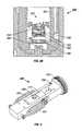
- FIG. 2Ais a drawing of the exterior of the FIB column of the present invention.
- FIG. 2Bshows the FIB column of FIG. 2A with a portion of the exterior cover removed to display a partial cross section.
- FIG. 3Ais a cross-sectional drawing of an emitter assembly in which the first gun lens element is separate from the extractor but at the same potential as the extractor
- FIG. 3Bis a cross sectional drawing of an emitter assembly in which the first gun lens element is attached to the extractor.
- FIG. 4is a drawing of an isolation valve activation mechanism suitable for use inside a vacuum chamber.
- FIG. 5is a drawing of a piezoelectrically driven X-Y aperture motion stage suitable for use inside a vacuum chamber.
- FIG. 6shows schematically a multiple beam system using a column of the present invention.
- FIGS. 2A and 2Bshow a preferred embodiment of the present invention.
- FIG. 2Ashows the exterior of an ion column 200 .
- High voltage cables 202provide the high voltage necessary to operate the optical elements in column 200 .
- An ion pump 204 attached to a flange 205evacuates a gun chamber 206 to a high or ultra high vacuum.
- a flange 208is used to secure column 200 to a system vacuum chamber (not shown), with the portion of column 200 containing the ion optical elements being positioned within the system vacuum chamber, which contains a work piece to which the ion beam is directed during operation.
- gun chamber 206is fabricated using a housing or gun bushing 210 of a dielectric material that forms the vacuum wall and provides mechanical support and high voltage isolation for the ion optical elements in the chamber.
- the lens elementsare preferably glued or brazed into the dielectric material of gun bushing 210 using a fixture to ensure the elements are accurately aligned.
- FIG. 2Ashows that there are no mechanical feedthroughs through the portion of column 200 that will be positioned in the system vacuum chamber.
- FIG. 2Bshows additional features of a preferred embodiment of the present invention.
- An emitter 220 , a suppressor 222 , an extractor 224 and a first lens 226are combined into an ion emitter module 230 , which is easily replaced, if necessary, in the field.
- the gun chamber 206which includes its own vacuum pump, an ion pump (not shown) attached to port 204 , can be vacuum isolated from the system vacuum chamber using an isolation valve 240 .
- the isolation valve assembly 240 , an X-Y aperture stage of an automated variable aperture 242 , as well as deflection plates 246 and a final lens 248are located outside of the gun chamber 206 and within the system vacuum chamber.
- the optical columnpreferably has a short length to minimize beam broadening by mutual repulsion by the ions. Reducing the ion column optical length shortens the ion path to the target. To facilitate this short length while providing the ability of the column to extend into the system vacuum chamber, the isolation valve activation mechanism and aperture changing drive mechanism are preferably positioned within the system vacuum chamber. Positioning these mechanisms within the system vacuum chamber eliminates the requirement for corresponding mechanical feedthroughs that restrict the positioning of the ion column within the system vacuum chamber and increase system complexity.
- Gun bushing 210can be comprised of a ceramic, polymer, or even high resistivity semiconductor material and can optionally be contained within a metal column body (not shown).
- the optional metal bodyprovides a steady platform for the gun and can be used to magnetically shield the ion beam.
- O-rings of an elastomeric materialcan provide vacuum seals between the gun bushing 210 and the metal chamber.
- the system vacuum chambersurrounds gun bushing 210 , then the portion of the metal body around the gun bushing might not be needed, and the diameter of the gun can be reduced.
- the metal gun optical elementsare glued or brazed inside the gun bushing 210 using suitable tools and fixtures, and post machined for accuracy if needed.
- Such manufacturing techniquesare well known in the art of charged particle beam optics.
- a brazed assemblyis less likely to produce outgassing in the vacuum chamber, but brazing has the disadvantage of requiring the assembly to be heated to a high temperature during construction.
- the columnhas a narrow cross section and can be therefore deeply recessed into the main vacuum chamber. Recessing the column provides a relatively short optical path and reduces beam interactions, thereby improving ion beam optical properties.
- the wires from the gun optical elementsgo through holes in the side of gun bushing 210 and are glued for vacuum integrity.
- the wirescan be sealed by elastomeric O-rings, or can be fused or brazed into gun bushing 210 .
- These methodsprovide very simple electrical feedthroughs.
- the wiresare potted with standard high voltage, high temperature potting material. High voltage “flying leads” with connectors on their ends can be used, or the connectors can be potted to the gun bushing or into holes in the bushing. These methods provide simple connector means. Persons skilled in basic vacuum system fabrication techniques will be able to make such connectors, as well as the rest of ion column described herein, based upon the guidance provided in this specification.
- a vacuum pumppreferably an ion pump, may be placed on top of the main column flange and optionally has a vacuum valve to maintain vacuum in the vacuum pump when the gun is serviced, such as when the emitter assembly is replaced.
- the high voltage connectors as well as the gun access flangeneed to be removed for this servicing using a column using this configuration.
- an ion pumpcan be fastened to the side of the gun chamber top, and the various wires and other services to the gun and lower column can be connected to the outer perimeter of the gun bushing top.
- the emitter modulecan be accessed through the top center of the gun without removing some or all of the services described above.
- Isolation valve 240automated variable aperture 242 , and their associated activating or drive mechanisms are preferably positioned completely inside the main system vacuum chamber to provide a short column length.
- the isolation valveis a small mechanism, which is air-actuated by an air line down along the column chamber body.
- the AVApreferably uses a very small X-Y stage, preferably piezoelectrically actuated, which is vacuum compatible and has low magnetic fields.
- electroformed or electroetched aperturescan be employed for the medium to large size apertures.
- Conventional techniquescan be used to fabricate small apertures into thin (about 25 microns) metal sheets to about three microns accuracy.
- the aperturescan be formed by laser ablation or FIB milling, or by a combination of electroforming or electroetching plus laser ablation or FIB.
- two dimensional aperture arrays of about 100 aperturesmay be formed to provide long times (many months) between aperture replacements.
- FIG. 3Ashows one preferred design for an ion gun assembly 300 .
- Ion gun assembly 300includes an emitter assembly support 302 that supports and positions an emitter assembly 304 relative to a gun bushing 308 .
- Emitter assembly 304includes an emitter 312 , a suppressor 314 , an extractor cap 316 , and the extractor aperture 318 .
- Gun bushing 308supports a first gun lens element 320 , which is separate from the emitter assembly 304 and is maintained at the same electrical potential as extractor cap 316 .
- Gun bushing 308also supports a second gun lens element 322 and a third gun lens element 324 .
- An emitter assembly flange 330is used to secure emitter assembly support 302 in position within the gun vacuum chamber. As described above, gun bushing 308 can be surrounded by a steel chamber 332 .
- Ion gun assembly 300has the following advantages compared to the prior art:
- Replacing emitter assembly 304exchanges the emitter 312 , extractor cap 316 and the extractor aperture 318 as one assembly. This reduces the effort to replace these individual parts.
- the alignment between the emitter 312 and the extractor aperture 318can be more accurate than in prior art design.
- the radial runoutthat is, the offset of the axes of the individual parts from the axes of the assembly, can be kept very small by adjustments during assembly. In the prior art, this runout depended upon individual part clearances and tolerance stackups between multiple parts. Maintaining a small runout between the emitter and extractor aperture is particularly important for large beam applications, where spherical aberrations prevail.
- the first lens element 320By having the first lens element 320 remain in the chamber when the extractor is removed, the first lens element is protected from scratches and dust, which is important because the electric field stress on it is very large. Scratches or contamination can cause the lens element 320 to break down when subjected to a high voltage under normal operating conditions. Also, the first lens element 320 can be closely aligned with the other gun lens elements during assembly to minimize radial runout between those parts.
- emitter assembly support 302is movable in the X-Y plane to position the emitter 312 , suppressor 314 , extractor cap 316 and extractor aperture 318 assembly with respect to the gun lens 320 .
- emitter assembly 304can be a pre-positioned assembly, which fits into a precision recess in gun bushing 308 or first gun lens element 320 .
- FIG. 3Bshows an alternate design for an ion gun assembly 350 that includes an emitter assembly 352 mounted on a gun bushing 354 .
- Emitter assembly 352includes an emitter 356 , a suppressor 358 , an extractor 360 , and an extractor aperture 362 .
- a first gun lens element 364is attached to extractor 360 , rather than being mounted to gun bushing 354 as in ion gun 300 of FIG. 3 A.
- the design of FIG. 3Bis simpler, but the first gun lens element 364 , which forms the lower surface of the extractor 360 , is removed with the emitter assembly and is therefore more susceptible to being scratched and subsequently suffer high voltage breakdown.
- first gun lens element 364when the first gun lens element 364 is removed with the emitter assembly for emitter and extractor aperture replacement, precise alignment of first gun lens element 364 with the other gun lens elements, such as a lens element 366 and lens element 368 , is more difficult because first lens element 364 is mounted on the emitter assembly 352 and the other elements are mounted on gun bushing 354 .
- FIG. 4shows a preferred embodiment of an in-vacuum isolation valve mechanism 400 used on the column of FIGS. 2A and 2B.
- Sealed metal bellows 402uses air pressure fed through a hole 406 in the side of the gun to open a valve.
- Springs 404return the valve to the closed position when the air pressure is off.
- a wedge sealing surface on slider 410slides under the valve seat 408 placed at the base of the gun (not shown).
- An O-ring on the wedge surface of slider 410forms the valve seal.
- Valve seat 408has a hole through it to pass the ion beam from the gun to the lower column.
- FIG. 5shows a preferred aperture X-Y positioning stage 500 for moving an aperture array 502 to position a selected aperture in the ion beam path in the column of FIGS. 2A and 2B.
- Motion stage 500includes slots 504 for holding the aperture plate and two piezoelectric drives 506 (one shown) to provide high speed, high-resolution motion of positioning stage 500 in the X and Y directions.
- a stage 510moves in the X direction and a stage 512 moves in a Y direction, each on linear bearings 514 .
- Linear encoders 508provide accurate feedback of the X-Y stage motion. Aperture positions are reproducible to better than one micron.
- FIG. 6shows a dual beam system 600 using a FIB column 602 as described above.
- FIB column 602includes an AVA drive mechanism 500 and a vacuum isolation valve 400 , both of which are positioned within a system vacuum chamber 604 .
- AVA drive mechanism 500is contained within system vacuum chamber 604 , and only electrical connections are required to extend outside of system vacuum chamber 604 .
- the vacuum isolation valve mechanism 400is contained within system vacuum chamber 604 , and only an air line for actuating the valve is required to extend outside of the chamber.
- Dual beam system 600also includes a second beam system, in this case scanning electron microscope 610 , directed toward the same work piece 608 as the FIB column.
- the example provided illustrated a gun bushingother portions of the optical column can be placed in a dielectric bushing.
- the inventionis not limited to use with a liquid metal focused ion beam source, but can be used to construct other charged particle beam systems.
- the present inventionthere are no mechanical feedthroughs into the system vacuum chamber. All mechanical devices are contained within the system vacuum chamber and only control means, such as electrical wires or pneumatic tubes, penetrate the vacuum chamber wall. Since the emitter assembly is prealigned, it requires no complex electrical mechanical motion in an automated FIB system.
Landscapes
- Chemical & Material Sciences (AREA)
- Analytical Chemistry (AREA)
- Electron Sources, Ion Sources (AREA)
Abstract
Description
Claims (16)
Priority Applications (1)
| Application Number | Priority Date | Filing Date | Title |
|---|---|---|---|
| US09/982,110US6710338B2 (en) | 2000-10-18 | 2001-10-17 | Focused ion beam system |
Applications Claiming Priority (2)
| Application Number | Priority Date | Filing Date | Title |
|---|---|---|---|
| US24153600P | 2000-10-18 | 2000-10-18 | |
| US09/982,110US6710338B2 (en) | 2000-10-18 | 2001-10-17 | Focused ion beam system |
Publications (2)
| Publication Number | Publication Date |
|---|---|
| US20020084426A1 US20020084426A1 (en) | 2002-07-04 |
| US6710338B2true US6710338B2 (en) | 2004-03-23 |
Family
ID=22911097
Family Applications (1)
| Application Number | Title | Priority Date | Filing Date |
|---|---|---|---|
| US09/982,110Expired - LifetimeUS6710338B2 (en) | 2000-10-18 | 2001-10-17 | Focused ion beam system |
Country Status (5)
| Country | Link |
|---|---|
| US (1) | US6710338B2 (en) |
| EP (1) | EP1332509A4 (en) |
| JP (1) | JP4473964B2 (en) |
| AU (1) | AU2002216639A1 (en) |
| WO (1) | WO2002033727A1 (en) |
Cited By (9)
| Publication number | Priority date | Publication date | Assignee | Title |
|---|---|---|---|---|
| US20030185967A1 (en)* | 2002-03-27 | 2003-10-02 | Eby Raymond K. | Method and apparatus for aligning patterns on a substrate |
| US20050127304A1 (en)* | 2003-12-08 | 2005-06-16 | Hiroyasu Kaga | Liquid metal ion gun |
| US20060284112A1 (en)* | 2005-05-27 | 2006-12-21 | Satoshi Tomimatsu | Apparatus and method for specimen fabrication |
| WO2010052712A1 (en)* | 2008-11-05 | 2010-05-14 | El-Mul Technologies Ltd | Charged particle emitting assembly |
| US8581481B1 (en)* | 2011-02-25 | 2013-11-12 | Applied Physics Technologies, Inc. | Pre-aligned thermionic emission assembly |
| US20150090897A1 (en)* | 2013-09-27 | 2015-04-02 | Varian Semiconductor Equipment Associates, Inc. | SiC Coating In An Ion Implanter |
| US9214313B2 (en) | 2010-04-09 | 2015-12-15 | E.A. Fischione Instruments, Inc. | Ion source with independent power supplies |
| WO2017127226A1 (en)* | 2016-01-19 | 2017-07-27 | Brown International Corporation, Llc | Method and apparatus for citrus juice processing |
| US11049688B2 (en)* | 2018-10-01 | 2021-06-29 | Nuflare Technology, Inc. | Charged particle beam irradiation apparatus |
Families Citing this family (8)
| Publication number | Priority date | Publication date | Assignee | Title |
|---|---|---|---|---|
| EP1171901B1 (en)* | 2000-02-09 | 2008-10-08 | Fei Company | Multi-column fib for nanofabrication applications |
| DE60313282T2 (en)* | 2003-03-03 | 2007-12-27 | ICT Integrated Circuit Testing Gesellschaft für Halbleiterprüftechnik mbH | Device for charged particles with cleaning unit and method for its operation |
| JP4814610B2 (en)* | 2005-10-25 | 2011-11-16 | 株式会社ニューフレアテクノロジー | Suction aid |
| FR2957455B1 (en)* | 2010-03-09 | 2012-04-20 | Essilor Int | PROTECTIVE ENVELOPE FOR CANON IONS, DEVICE FOR DEPOSITING VACUUM EVAPORATION MATERIALS COMPRISING SUCH A PROTECTIVE ENVELOPE AND METHOD FOR DEPOSITING MATERIALS |
| JP5259688B2 (en)* | 2010-12-09 | 2013-08-07 | 本田技研工業株式会社 | Scanning electron microscope |
| WO2014011292A1 (en)* | 2012-07-13 | 2014-01-16 | Omniprobe, Inc. | Gas injection system for energetic-beam instruments |
| KR101384964B1 (en)* | 2012-07-23 | 2014-04-14 | 에스엔유 프리시젼 주식회사 | Valve for maintaining vacuum and scanning electron microscope using the same |
| US9006689B2 (en)* | 2013-03-26 | 2015-04-14 | Ion Technology Solutions, Llc | Source bushing shielding |
Citations (12)
| Publication number | Priority date | Publication date | Assignee | Title |
|---|---|---|---|---|
| US4698236A (en)* | 1984-10-26 | 1987-10-06 | Ion Beam Systems, Inc. | Augmented carbonaceous substrate alteration |
| US5196707A (en)* | 1991-03-04 | 1993-03-23 | Etec Systems, Inc. | Low aberration field emission electron gun |
| US5342950A (en)* | 1989-12-06 | 1994-08-30 | Basf Aktiengesellschaft | Preparation of quinophthalone derivatives |
| US5844416A (en)* | 1995-11-02 | 1998-12-01 | Sandia Corporation | Ion-beam apparatus and method for analyzing and controlling integrated circuits |
| US6032513A (en)* | 1997-06-30 | 2000-03-07 | Texas Instruments Incorporated | Apparatus and method for measuring contaminants in semiconductor processing chemicals |
| US6107626A (en)* | 1997-10-14 | 2000-08-22 | The University Of Washington | Device and method for forming ions |
| US6268608B1 (en)* | 1998-10-09 | 2001-07-31 | Fei Company | Method and apparatus for selective in-situ etching of inter dielectric layers |
| US6300628B1 (en)* | 1997-12-11 | 2001-10-09 | Seiko Instruments Inc. | Focused ion beam machining method and device thereof |
| US6331713B1 (en)* | 1999-10-06 | 2001-12-18 | Applied Materials, Inc. | Movable ion source assembly |
| US6348689B1 (en)* | 1998-05-15 | 2002-02-19 | Seiko Instruments Inc. | Focused ion beam apparatus |
| US6365905B1 (en)* | 1998-06-03 | 2002-04-02 | Seiko Instruments Inc. | Focused ion beam processing apparatus |
| US6407001B1 (en)* | 2000-06-30 | 2002-06-18 | Intel Corporation | Focused ion beam etching of copper |
Family Cites Families (8)
| Publication number | Priority date | Publication date | Assignee | Title |
|---|---|---|---|---|
| NL278803A (en)* | 1961-05-25 | |||
| DE2657114C2 (en)* | 1976-12-16 | 1984-05-03 | Institut elektrosvarki imeni E.O. Patona Akademii Nauk Ukrainskoj SSR, Kiev | Acceleration system for a bundle of charged particles in an electron or ion beam cannon |
| US4847504A (en)* | 1983-08-15 | 1989-07-11 | Applied Materials, Inc. | Apparatus and methods for ion implantation |
| US4661709A (en)* | 1985-06-28 | 1987-04-28 | Control Data Corporation | Modular all-electrostatic electron-optical column and assembly of said columns into an array and method of manufacture |
| US4985634A (en)* | 1988-06-02 | 1991-01-15 | Oesterreichische Investitionskredit Aktiengesellschaft And Ionen Mikrofabrications | Ion beam lithography |
| US5241182A (en)* | 1991-06-18 | 1993-08-31 | Fei Company | Precision electrostatic lens system and method of manufacture |
| JP2732961B2 (en)* | 1991-07-18 | 1998-03-30 | 株式会社日立製作所 | Charged particle beam equipment |
| EP1171901B1 (en)* | 2000-02-09 | 2008-10-08 | Fei Company | Multi-column fib for nanofabrication applications |
- 2001
- 2001-10-17EPEP01987944Apatent/EP1332509A4/ennot_activeWithdrawn
- 2001-10-17AUAU2002216639Apatent/AU2002216639A1/ennot_activeAbandoned
- 2001-10-17JPJP2002537029Apatent/JP4473964B2/ennot_activeExpired - Lifetime
- 2001-10-17USUS09/982,110patent/US6710338B2/ennot_activeExpired - Lifetime
- 2001-10-17WOPCT/US2001/032502patent/WO2002033727A1/enactiveApplication Filing
Patent Citations (12)
| Publication number | Priority date | Publication date | Assignee | Title |
|---|---|---|---|---|
| US4698236A (en)* | 1984-10-26 | 1987-10-06 | Ion Beam Systems, Inc. | Augmented carbonaceous substrate alteration |
| US5342950A (en)* | 1989-12-06 | 1994-08-30 | Basf Aktiengesellschaft | Preparation of quinophthalone derivatives |
| US5196707A (en)* | 1991-03-04 | 1993-03-23 | Etec Systems, Inc. | Low aberration field emission electron gun |
| US5844416A (en)* | 1995-11-02 | 1998-12-01 | Sandia Corporation | Ion-beam apparatus and method for analyzing and controlling integrated circuits |
| US6032513A (en)* | 1997-06-30 | 2000-03-07 | Texas Instruments Incorporated | Apparatus and method for measuring contaminants in semiconductor processing chemicals |
| US6107626A (en)* | 1997-10-14 | 2000-08-22 | The University Of Washington | Device and method for forming ions |
| US6300628B1 (en)* | 1997-12-11 | 2001-10-09 | Seiko Instruments Inc. | Focused ion beam machining method and device thereof |
| US6348689B1 (en)* | 1998-05-15 | 2002-02-19 | Seiko Instruments Inc. | Focused ion beam apparatus |
| US6365905B1 (en)* | 1998-06-03 | 2002-04-02 | Seiko Instruments Inc. | Focused ion beam processing apparatus |
| US6268608B1 (en)* | 1998-10-09 | 2001-07-31 | Fei Company | Method and apparatus for selective in-situ etching of inter dielectric layers |
| US6331713B1 (en)* | 1999-10-06 | 2001-12-18 | Applied Materials, Inc. | Movable ion source assembly |
| US6407001B1 (en)* | 2000-06-30 | 2002-06-18 | Intel Corporation | Focused ion beam etching of copper |
Cited By (25)
| Publication number | Priority date | Publication date | Assignee | Title |
|---|---|---|---|---|
| US7279046B2 (en) | 2002-03-27 | 2007-10-09 | Nanoink, Inc. | Method and apparatus for aligning patterns on a substrate |
| US20030185967A1 (en)* | 2002-03-27 | 2003-10-02 | Eby Raymond K. | Method and apparatus for aligning patterns on a substrate |
| US20080147346A1 (en)* | 2002-03-27 | 2008-06-19 | Nanolnk, Inc. | Method and apparatus for aligning patterns on a substrate |
| US8043652B2 (en) | 2002-03-27 | 2011-10-25 | Nanoink, Inc. | Method and apparatus for aligning patterns on a substrate |
| US20060097186A1 (en)* | 2003-12-08 | 2006-05-11 | Hitachi High-Technologies | Liquid metal ion gun |
| US7211805B2 (en) | 2003-12-08 | 2007-05-01 | Hitachi High-Technologies Corporation | Liquid metal ion gun |
| US20070257200A1 (en)* | 2003-12-08 | 2007-11-08 | Hitachi High-Technologies Corporation | Liquid metal ion gun |
| US7005651B2 (en)* | 2003-12-08 | 2006-02-28 | Hitachi High-Technologies Corporation | Liquid metal ion gun |
| US7420181B2 (en) | 2003-12-08 | 2008-09-02 | Hitachi High-Technologies Corporation | Liquid metal ion gun |
| US20080210883A1 (en)* | 2003-12-08 | 2008-09-04 | Hitachi High-Technologies Corporation | Liquid metal ion gun |
| US20050127304A1 (en)* | 2003-12-08 | 2005-06-16 | Hiroyasu Kaga | Liquid metal ion gun |
| US7804073B2 (en) | 2003-12-08 | 2010-09-28 | Hitachi High-Technologies Corporation | Liquid metal ion gun |
| US20060284112A1 (en)* | 2005-05-27 | 2006-12-21 | Satoshi Tomimatsu | Apparatus and method for specimen fabrication |
| US7482603B2 (en)* | 2005-05-27 | 2009-01-27 | Hitachi High-Technologies Corporation | Apparatus and method for specimen fabrication |
| US7989782B2 (en) | 2005-05-27 | 2011-08-02 | Hitachi High-Technologies Corporation | Apparatus and method for specimen fabrication |
| WO2010052712A1 (en)* | 2008-11-05 | 2010-05-14 | El-Mul Technologies Ltd | Charged particle emitting assembly |
| US9214313B2 (en) | 2010-04-09 | 2015-12-15 | E.A. Fischione Instruments, Inc. | Ion source with independent power supplies |
| US8581481B1 (en)* | 2011-02-25 | 2013-11-12 | Applied Physics Technologies, Inc. | Pre-aligned thermionic emission assembly |
| US8987982B2 (en) | 2011-02-25 | 2015-03-24 | Applied Physics Technologies, Inc. | Method of producing rapid heating of a cathode installed in a thermionic emission assembly |
| US20150090897A1 (en)* | 2013-09-27 | 2015-04-02 | Varian Semiconductor Equipment Associates, Inc. | SiC Coating In An Ion Implanter |
| US9384937B2 (en)* | 2013-09-27 | 2016-07-05 | Varian Semiconductor Equipment Associates, Inc. | SiC coating in an ion implanter |
| US20160293378A1 (en)* | 2013-09-27 | 2016-10-06 | Varian Semiconductor Equipment Associates, Inc. | SiC Coating In an Ion Implanter |
| US9793086B2 (en)* | 2013-09-27 | 2017-10-17 | Varian Semiconductor Equipment Associates, Inc. | SiC coating in an ion implanter |
| WO2017127226A1 (en)* | 2016-01-19 | 2017-07-27 | Brown International Corporation, Llc | Method and apparatus for citrus juice processing |
| US11049688B2 (en)* | 2018-10-01 | 2021-06-29 | Nuflare Technology, Inc. | Charged particle beam irradiation apparatus |
Also Published As
| Publication number | Publication date |
|---|---|
| AU2002216639A1 (en) | 2002-04-29 |
| JP4473964B2 (en) | 2010-06-02 |
| US20020084426A1 (en) | 2002-07-04 |
| JP2004512641A (en) | 2004-04-22 |
| EP1332509A4 (en) | 2007-06-06 |
| EP1332509A1 (en) | 2003-08-06 |
| WO2002033727A1 (en) | 2002-04-25 |
Similar Documents
| Publication | Publication Date | Title |
|---|---|---|
| US6710338B2 (en) | Focused ion beam system | |
| US6797953B2 (en) | Electron beam system using multiple electron beams | |
| KR102375188B1 (en) | Charged particle beam device, interchangeable multi-aperture arrangement for a charged particle beam device, and method for operating a charged particle beam device | |
| Rempfer et al. | Design and performance of a high-resolution photoelectron microscope | |
| US5399860A (en) | Electron optic column and scanning electron microscope | |
| JP2004363085A (en) | Inspection apparatus by charged particle beam and method for manufacturing device using inspection apparatus | |
| EP1171901A1 (en) | Multi-column fib for nanofabrication applications | |
| US20020148971A1 (en) | Lens assembly for electron beam column | |
| KR20250083589A (en) | Electrostatic lens designs | |
| WO2005071708A2 (en) | Focussing lens for charged particle beams | |
| KR20190117738A (en) | Exposure equipment | |
| WO2001059806A1 (en) | Through-the-lens collection of secondary particles for a focused ion beam system | |
| US20230207252A1 (en) | Actuator arrangement and electron-optical column | |
| TW202226297A (en) | High voltage feedthrough and connector for a charged particle apparatus | |
| US8502163B2 (en) | Charged particle beam device, vacuum valve therefor and operation thereof | |
| EP3982391A1 (en) | Electron-optical assembly comprising electromagnetic shielding | |
| EP4307335A1 (en) | Isolating spacer for electron-optical assembly | |
| EP4290550A1 (en) | Electron-optical device | |
| WO2024199722A1 (en) | Multi-beam particle microscope with a quickly replaceable particle source, and method for quickly replacing a particle source in the multi-beam particle microscope | |
| WO2024013041A1 (en) | Electron-optical assembly | |
| JPH0786350A (en) | Electron beam equipment |
Legal Events
| Date | Code | Title | Description |
|---|---|---|---|
| AS | Assignment | Owner name:FEI COMPANY, OREGON Free format text:ASSIGNMENT OF ASSIGNORS INTEREST;ASSIGNOR:PROCYK, DREW;REEL/FRAME:012601/0362 Effective date:20020117 Owner name:FEI COMPANY, OREGON Free format text:ASSIGNMENT OF ASSIGNORS INTEREST;ASSIGNORS:GERLACH, ROBERT L.;TESCH, PAUL;MARTIN, NOEL PAUL;AND OTHERS;REEL/FRAME:012604/0642;SIGNING DATES FROM 20020111 TO 20020114 | |
| STCF | Information on status: patent grant | Free format text:PATENTED CASE | |
| FPAY | Fee payment | Year of fee payment:4 | |
| REMI | Maintenance fee reminder mailed | ||
| AS | Assignment | Owner name:J.P. MORGAN EUROPE LIMITED, AS ALTERNATIVE CURRENC Free format text:SECURITY AGREEMENT;ASSIGNOR:FEI COMPANY;REEL/FRAME:021064/0319 Effective date:20080604 Owner name:JP MORGAN CHASE BANK, N.A. (AS ADMINISTRATIVE AGEN Free format text:SECURITY AGREEMENT;ASSIGNOR:FEI COMPANY;REEL/FRAME:021064/0319 Effective date:20080604 | |
| CC | Certificate of correction | ||
| FPAY | Fee payment | Year of fee payment:8 | |
| FPAY | Fee payment | Year of fee payment:12 | |
| AS | Assignment | Owner name:FEI COMPANY, OREGON Free format text:RELEASE BY SECURED PARTY;ASSIGNORS:JPMORGAN CHASE BANK, N.A.;J.P. MORGAN EUROPE LIMITED;REEL/FRAME:038328/0787 Effective date:20160324 |