US6710288B2 - Method and apparatus for aligning a work piece in a laser drilling system - Google Patents
Method and apparatus for aligning a work piece in a laser drilling systemDownload PDFInfo
- Publication number
- US6710288B2 US6710288B2US10/266,944US26694402AUS6710288B2US 6710288 B2US6710288 B2US 6710288B2US 26694402 AUS26694402 AUS 26694402AUS 6710288 B2US6710288 B2US 6710288B2
- Authority
- US
- United States
- Prior art keywords
- workpiece
- alignment
- planar surface
- drilling
- incident
- Prior art date
- Legal status (The legal status is an assumption and is not a legal conclusion. Google has not performed a legal analysis and makes no representation as to the accuracy of the status listed.)
- Expired - Fee Related
Links
Images


Classifications
- B—PERFORMING OPERATIONS; TRANSPORTING
- B23—MACHINE TOOLS; METAL-WORKING NOT OTHERWISE PROVIDED FOR
- B23K—SOLDERING OR UNSOLDERING; WELDING; CLADDING OR PLATING BY SOLDERING OR WELDING; CUTTING BY APPLYING HEAT LOCALLY, e.g. FLAME CUTTING; WORKING BY LASER BEAM
- B23K26/00—Working by laser beam, e.g. welding, cutting or boring
- B23K26/02—Positioning or observing the workpiece, e.g. with respect to the point of impact; Aligning, aiming or focusing the laser beam
- B23K26/06—Shaping the laser beam, e.g. by masks or multi-focusing
- B23K26/067—Dividing the beam into multiple beams, e.g. multifocusing
- B—PERFORMING OPERATIONS; TRANSPORTING
- B23—MACHINE TOOLS; METAL-WORKING NOT OTHERWISE PROVIDED FOR
- B23K—SOLDERING OR UNSOLDERING; WELDING; CLADDING OR PLATING BY SOLDERING OR WELDING; CUTTING BY APPLYING HEAT LOCALLY, e.g. FLAME CUTTING; WORKING BY LASER BEAM
- B23K26/00—Working by laser beam, e.g. welding, cutting or boring
- B23K26/02—Positioning or observing the workpiece, e.g. with respect to the point of impact; Aligning, aiming or focusing the laser beam
- B23K26/04—Automatically aligning, aiming or focusing the laser beam, e.g. using the back-scattered light
- B23K26/042—Automatically aligning the laser beam
- B—PERFORMING OPERATIONS; TRANSPORTING
- B23—MACHINE TOOLS; METAL-WORKING NOT OTHERWISE PROVIDED FOR
- B23K—SOLDERING OR UNSOLDERING; WELDING; CLADDING OR PLATING BY SOLDERING OR WELDING; CUTTING BY APPLYING HEAT LOCALLY, e.g. FLAME CUTTING; WORKING BY LASER BEAM
- B23K26/00—Working by laser beam, e.g. welding, cutting or boring
- B23K26/02—Positioning or observing the workpiece, e.g. with respect to the point of impact; Aligning, aiming or focusing the laser beam
- B23K26/06—Shaping the laser beam, e.g. by masks or multi-focusing
- B23K26/062—Shaping the laser beam, e.g. by masks or multi-focusing by direct control of the laser beam
- B23K26/0622—Shaping the laser beam, e.g. by masks or multi-focusing by direct control of the laser beam by shaping pulses
- B23K26/0624—Shaping the laser beam, e.g. by masks or multi-focusing by direct control of the laser beam by shaping pulses using ultrashort pulses, i.e. pulses of 1ns or less
- H—ELECTRICITY
- H05—ELECTRIC TECHNIQUES NOT OTHERWISE PROVIDED FOR
- H05K—PRINTED CIRCUITS; CASINGS OR CONSTRUCTIONAL DETAILS OF ELECTRIC APPARATUS; MANUFACTURE OF ASSEMBLAGES OF ELECTRICAL COMPONENTS
- H05K3/00—Apparatus or processes for manufacturing printed circuits
- H05K3/0008—Apparatus or processes for manufacturing printed circuits for aligning or positioning of tools relative to the circuit board
- H—ELECTRICITY
- H05—ELECTRIC TECHNIQUES NOT OTHERWISE PROVIDED FOR
- H05K—PRINTED CIRCUITS; CASINGS OR CONSTRUCTIONAL DETAILS OF ELECTRIC APPARATUS; MANUFACTURE OF ASSEMBLAGES OF ELECTRICAL COMPONENTS
- H05K3/00—Apparatus or processes for manufacturing printed circuits
- H05K3/0011—Working of insulating substrates or insulating layers
- H05K3/0017—Etching of the substrate by chemical or physical means
- H05K3/0026—Etching of the substrate by chemical or physical means by laser ablation
Definitions
- the present inventionrelates to laser drilling systems, and more particularly, to a method for aligning a workpiece in a laser drilling system.
- Ultrafast lasersgenerate intense laser pulses with durations from roughly 10 ⁇ 11 seconds (10 picoseconds) to 10 ⁇ 14 seconds (10 femtoseconds).
- Short pulse lasersgenerate intense laser pulses with durations from roughly 10 ⁇ 10 seconds (100 picoseconds) to 10 ⁇ 11 seconds (10 picoseconds).
- These lasersare also a useful tool for milling or drilling holes in a wide range of materials. Hole sizes as small as a few microns, even sub-microns, can readily be drilled. High aspect ratio holes can be drilled in hard materials, such as cooling channels in turbine blades, nozzles in ink-jet printers, or via holes in printed circuit boards.
- Beam splitting devicessuch as diffractive optical elements (DOE) are currently used in laser micromachining to divide a single beam into multiple beams to allow for parallel processing of the workpiece (material to be drilled).
- DOEdiffractive optical elements
- the multiple sub-beamsare focused at a focal plane that is a specific distance from the final lens in a laser drilling system.
- the focal planeis a plane located at a distance f, which is equal to the focal length of the lens and normal to the optical axis of the beam delivery system.
- the target areais comprised of the area of the workpiece where the hole pattern is drilled.
- the entire target area of the workpiecemust be positioned in the focal plane of the sub-beams to ensure consistency of size and shape across all holes being drilled. If the entire target area is not in the focal plane, some of the beams drilling the holes in workpiece will be out of focus when they reach the workpiece, thereby causing the drilled holes not to meet size and shape requirements. What is needed is a way to keep the target area of the workpiece in the focal plane of the laser beam in a laser drilling system.
- a methodfor aligning a workpiece in a laser drilling system.
- the methodincludes: providing a workpiece having at least two substantially planar and parallel surfaces, including a first planar surface in which ablations are formed therein by the laser drilling system; propagating an alignment beam of light towards a second planar surface of the workpiece, the alignment beam being incident on and reflected by the second planar surface, thereby forming a reflected beam of light; measuring a reflection angle of the reflected beam; and determining alignment information for the workpiece based on the measured reflection angle of the reflected beam.
- the methodmay further include adjusting alignment of the workpiece based on the alignment information.
- FIG. 1Ais a diagram illustrating the optical beam paths, including an alignment beam path, in accordance with the present invention
- FIG. 1Bis a diagram depicting the primary components of an exemplary laser drilling system in accordance with the present invention.
- FIG. 2is a diagram illustrating how lateral resolution is measured between the alignment beam and the reflected beam
- FIG. 3is a flowchart depicting an exemplary method for aligning a workpiece in a laser drilling system in accordance with the present invention
- FIG. 4is a perspective view illustrating the primary components of an ink-jet printer.
- FIG. 5is a cross-sectional schematic view of an exemplary ink-jet head.
- FIG. 1Ashows the optical beam paths of a laser drilling system 100 , including a drilling laser 110 , emitting a drilling beam 115 ; a first mirror 120 ; a second mirror 121 ; a third mirror 122 ; a fourth mirror 123 ; an alignment laser 130 , with an aperture 132 emitting an aligning beam 135 ; an optical path 140 , an aperture 141 , and an aperture 142 .
- Drilling laser 110is a laser for drilling holes in workpieces. Drilling laser 110 provides sufficient pulse energy to ablate material in a workpiece. Drilling laser 110 emits drilling beam 115 .
- First mirror 120 , second mirror 121 , third mirror 122 , and fourth mirror 123are conventional laser mirrors used to reflect drilling beam 115 and aligning beam 135 in laser drilling system 100 .
- second mirror 121is a scan mirror that implements a laser milling algorithm (not shown) and guides drilling beam 115 to create the desired shape in the workpiece.
- Alignment laser 130is a counter-propagating, visible laser used to ensure that the workpiece is in the focal plane of drilling laser 110 .
- Alignment laser 130emits aligning beam 135 from aperture 132 .
- alignment laser 130is a HeNe laser with a narrow, well-defined beam, whereas drilling laser 110 is infrared with a larger, less precisely defined beam size.
- Optical path 140is the path of drilling beam 115 through laser drilling system 100 .
- drilling beam 115 and aligning beam 135are co-linear but counter-propagating along optical path 140 .
- Apertures 141 and 142are used in the initial alignment of laser drilling system 100 .
- Apertures 141 and 142are placed between mirrors 121 and 122 as shown in FIG. 1 .
- the centerpoint of apertures 141 and. 142define optical path 140 .
- the first stepis turning on drilling laser 110 , emitting drilling beam 115 , and mirrors 120 and 121 are adjusted to guide drilling beam 115 through apertures 141 and 142 .
- the next stepis turning off drilling laser 110 , and turning on alignment laser 130 , emitting aligning beam 135 .
- Mirrors 123 and 122are adjusted to guide aligning beam 135 through apertures 142 and 141 .
- FIG. 1Alaser drilling system 100 is shown partially assembled.
- FIG. 1Ashows drilling beam 115 and aligning beam 135 in alignment in optical path 140 .
- FIG. 1Arepresents how mirrors and lasers must be assembled and configured prior to the addition of additional elements and the workpiece to laser drilling system 100 . Once laser drilling system 100 is partially assembled and aligned as shown in FIG. 1A, then further assembly can proceed.
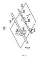
- FIG. 1Bshows laser drilling system 100 including the elements in FIG. 1A as well as additional elements, including: a beam expander 125 , a beamsplitter 150 , a scan lens 153 , a workpiece 155 on a stage 160 with a hole 161 , an angle ( ⁇ ) 165 , and a reflecting beam 170 traveling along reflecting path 172 .
- FIG. 1Bis not the only configuration of laser drilling system 100 possible.
- Laser drilling system 100 as shown in FIG. 1Bcontains only a exemplary set of elements; other elements may be employed by laser drilling system 100 .
- laser drilling system 100may include a shutter, an attenuator, a spinning half wave plate, a scan mirror, a microfilter, and/or an image transfer lens.
- Beam expander 125is used in the present invention to match the spot size of drilling beam 115 to the pupil size of scan lens 153 .
- Beamsplitter 150is used to split drilling beam 115 into sub-beams to allow for parallel drilling of holes in workpiece 155 .
- beamsplitter 150is a diffractive optical element (DOE) splitting drilling beam 115 into 152 sub-beams in the form of a 4 ⁇ 38 beam array.
- DOEdiffractive optical element
- Scan lens 153determines the spot size of the sub-beams upon workpiece 155 . Telecentricity is required to keep the incident angle between the sub-beams and workpiece 155 perpendicular, which is necessary to drill parallel holes in workpiece 155 .
- Workpiece 155is the target of laser drilling system 100 .
- the workpiece 155is generally defined by at least two substantially planar surfaces, such as a thin foil composed of a metal or plastic material.
- the two planar surfacemay be oriented parallel to each other.
- Workpiece 155is secured on tip/tilt stage 160 with a vacuum (not shown) or other known means.
- Stage 160(also referred to herein as a workpiece holder) is used to position workpiece 155 in optical path 140 .
- Stage 160is a tip/tilt stage with a hole 161 through stage 160 in the area around optical path 140 . Hole 161 is required to allow aligning beam 135 to be incident upon workpiece 155 and reflect back towards third mirror 122 .
- Stage 160has a tip/tilt mechanism to allow adjustments that ensure workpiece 155 is in the focal plane of the sub-beams of drilling beam 115 .
- the tip/tilt mechanism inside stage 160is electronic; alternatively, the tip/tilt mechanism is mechanical or a manual knob.
- FIG. 1Bshows an example of the tip/tilt function of stage 160 with the dashed outline of stage 160 and workpiece 155 showing a slight clockwise rotation of stage 160 and workpiece 155 .
- Angle ( ⁇ ) 165is the angle between aligning beam 135 and reflecting beam 170 between workpiece 155 and fourth mirror 123 .
- Reflecting beam 170is the reflection of aligning beam 135 from workpiece 155 .
- Reflecting path 172is the optical path of reflecting beam 170 .
- drilling laser 110emits drilling beam 115 along optical path 140 .
- Drilling beam 115propagates along optical path 140 , where it is incident upon first mirror 120 .
- First mirror 120redirects drilling beam 115 along optical path 140 , where it is incident upon beam expander 125 .
- Beam expandermatches the width of drilling beam 115 to the pupil size of scan lens 153 .
- Drilling beam 115exits beam expander 125 and propagates along the optical path where it is incident upon second mirror 121 .
- Second mirror 121redirects drilling beam 115 along optical path 140 , where it is incident upon beamsplitter 150 .
- Beamsplitter 150splits drilling beam 115 into a plurality of sub-beams, which allow parallel drilling of workpiece 155 .
- the sub-beamsexit beamsplitter 150 where they are incident upon scan lens 153 .
- Scan lens 153focuses the sub-beams upon workpiece 155 for parallel process drilling.
- Sub-beamsablate workpiece 155 in a pattern according to the pre-defined milling algorithm.
- Alignment laser 130emits aligning beam 135 , which counter-propagates along optical path 140 where it is incident upon fourth mirror 123 .
- Fourth mirror 123redirects aligning beam 135 along optical path 140 where it is incident upon third mirror 122 .
- Third mirror 122redirects aligning beam 135 along optical path 140 and through the opening in stage 160 , at the point where it is incident upon workpiece 155 .
- Workpiece 155reflects aligning beam 135 back towards third mirror 122 as reflecting beam 170 .
- Reflecting beam 170propagates along reflecting path 172 , where it is incident upon third mirror 122 .
- Third mirror 122redirects reflecting beam 170 along reflecting path 172 , where it is incident upon fourth mirror 123 .
- Fourth mirror 123redirects reflecting beam 170 along reflecting path 172 , where it is incident upon aperture 132 .
- the system operatoradjusts stage 160 based on information regarding the size of angle ( ⁇ ) 165 .
- FIG. 2shows a magnified view of alignment laser 130 and reflecting beam 170 with a lateral resolution ⁇ X 210 .
- Lateral resolution ⁇ X 210is the distance between aligning beam 135 and reflecting beam 170 on aperture 132 .
- Lateral resolution ⁇ X 210is a measured distance between the center point of the specular reflection of reflecting beam 170 on aperture 132 and the point where aligning beam 135 is emitted from alignment laser 130 .
- photodiodescan be placed directly adjacent to aperture 132 , positioned as close as possible, to determine lateral resolution ⁇ X 210 .
- FIG. 3illustrates an exemplary method 300 for aligning a workpiece in a laser drilling system.
- the methodgenerally includes the steps of: determining specifications and acceptable reflection angles; determining the optical beam path for the drilling laser; providing a counter-propagating alignment beam; aligning optical elements in relation to the optical path of the drilling beam; mounting a workpiece onto a workpiece holder; measuring a reflection angle; and adjusting the workpiece.
- the specifications for laser drilling system and the acceptable reflection anglesare determined in step 310 .
- This stepis accomplished by establishing the pattern size or size of target area, L, where the multiple holes are to be drilled in the workpiece 155 .
- ⁇ 0is the acceptable tilt angle of the workpiece that can yield a drilled workpiece that is within specification
- ⁇ Z 0is the acceptable depth of focus that yields a drilled workpiece to meet product specifications (change in axial distance Z)
- Lis the pattern size (roughly the radius of pattern to be drilled).
- Equation (1)states that the acceptable angle ⁇ 0 is equal to the axial distance reflecting beam 170 travels between workpiece 155 and aperture 132 , divided by the pattern size.
- step 320the laser drilling system 100 is assembled as shown in FIG. 1A, such that the optical path 140 is defined by the path of drilling beam 115 .
- the counter-propagating alignment beamis established at step 330 .
- alignment laser 130emits aligning beam 135 , which is a counter-propagating, visible laser beam.
- Alignment laser 130 , first mirror 120 , second mirror 121 , third mirror 122 , and fourth mirror 123are adjusted such that drilling beam 110 and aligning beam 135 propagate through apertures 141 and 142 , thereby forming optical path 140 .
- the remaining optical elements of laser drilling system 100are placed and centered in optical path 140 . It is readily understood that the alignment beam 135 may used to align certain optical elements, such as the scan lens 153 .
- the workpiece 155is the secured on stage 160 at step 350 .
- the workpiece 155 and stage 160are positioned to be perpendicular to optical path 140 .
- the remaining stepsprovide a way to precisely measure the axial position of workpiece 155 to ensure that the target area of workpiece 155 is perpendicular to optical path 140 .
- step 360an aligning beam 135 is reflected off the back side of workpiece 155 (and at that point becoming reflecting beam 170 ), is deflected by third mirror 122 and fourth mirror 123 , and is incident upon aperture 132 .
- the distance between the point where reflecting beam 170 is incident upon aperture 132 and the point where aligning beam 135 is emittedis called lateral resolution ⁇ X 210 .
- ⁇is the measured reflection angle 165 between aligning beam 135 and reflecting beam 170 ;
- ⁇ Xis the distance between aligning beam 135 and reflecting beam 170 on aperture 132 ;
- Zis the axial distance reflecting beam 170 travels between workpiece 155 and aperture 132 .
- the method 300determines if the reflection angle is within an acceptable range at step 370 .
- step 380if measured reflection angle ⁇ 165 is less than or equal to acceptable reflection angle ⁇ 0 , method 300 ends. If measured reflection angle ⁇ 165 is more than acceptable reflection angle ⁇ 0 , method 300 proceeds to step 380 .
- alignment data regarding the position of reflecting beam 170may be used to adjust stage 160 at step 380 .
- a system operatoradjusts stage 160 using mechanical means.
- a photodiode arraysends data regarding the position of reflecting beam 170 to stage control (not shown) and stage 160 is adjusted with the tip/tilt mechanism to decrease reflection angle ⁇ 165 .
- the method 300then returns to step 360 .
- an ink-jet printer 1140includes an ink-jet head 1141 capable of recording on a recording medium 1142 via a pressure generator.
- the ink-jet head 1141is mounted on a carriage 1144 capable of reciprocating movement along a carriage shaft 1143 .
- ink droplets emitted from the ink-jet head 1141are deposited on the recording medium 1142 , such as a sheet of copy paper.
- the ink-jet head 1141is structured such that it can reciprocate in a primary scanning direction X in parallel with the carriage shaft 1143 ; whereas the recording medium 1142 is timely conveyed by rollers 1145 in a secondary scanning direction Y.
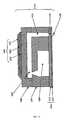
- FIG. 5further illustrates the construction of an exemplary ink-jet head 1141 .
- the ink-jet headis primarily comprised of a pressure generator 1104 and a nozzle plate 1114 .
- the pressure generator 1104is a piezoelectric system having an upper electrode 1101 , a piezoelectric element 1102 , and a lower electrode 1103 .
- a piezoelectric systemis presently preferred, it is envisioned that other types of systems (e.g., a thermal-based system) may also be employed by the ink-jet head 1141 .
- the nozzle plate 1114is further comprised of a nozzle substrate 1112 and a water repellent layer 1113 .
- the nozzle substrate 1112may be constructed from a metal or resin material; whereas the water repellant layer 1113 is made of fluororesin or silicone resin material.
- the nozzle substrate 1112is made of stainless steel having a thickness of 50 um and the water repellent layer 1113 is made of a fluororesin having a thickness of 0.1 um.
- the ink-jet head 1141further includes an ink supplying passage 1109 , a pressure chamber 1105 , and an ink passage 1111 disposed between the pressure generator 1104 and the nozzle plate 1114 .
- ink droplets 1120are ejected from the nozzle 110 .
- the nozzle 1110is preferably formed without flash and foreign matter (e.g., carbon, etc.) in the nozzle plate.
- the accuracy of the nozzle outlet diameteris 20 um ⁇ 1.5 um.
Landscapes
- Physics & Mathematics (AREA)
- Optics & Photonics (AREA)
- Engineering & Computer Science (AREA)
- Plasma & Fusion (AREA)
- Mechanical Engineering (AREA)
- Laser Beam Processing (AREA)
Abstract
Description


Claims (18)
Priority Applications (1)
| Application Number | Priority Date | Filing Date | Title |
|---|---|---|---|
| US10/266,944US6710288B2 (en) | 2002-07-25 | 2002-10-08 | Method and apparatus for aligning a work piece in a laser drilling system |
Applications Claiming Priority (2)
| Application Number | Priority Date | Filing Date | Title |
|---|---|---|---|
| US39838102P | 2002-07-25 | 2002-07-25 | |
| US10/266,944US6710288B2 (en) | 2002-07-25 | 2002-10-08 | Method and apparatus for aligning a work piece in a laser drilling system |
Publications (2)
| Publication Number | Publication Date |
|---|---|
| US20040016728A1 US20040016728A1 (en) | 2004-01-29 |
| US6710288B2true US6710288B2 (en) | 2004-03-23 |
Family
ID=30772607
Family Applications (1)
| Application Number | Title | Priority Date | Filing Date |
|---|---|---|---|
| US10/266,944Expired - Fee RelatedUS6710288B2 (en) | 2002-07-25 | 2002-10-08 | Method and apparatus for aligning a work piece in a laser drilling system |
Country Status (1)
| Country | Link |
|---|---|
| US (1) | US6710288B2 (en) |
Cited By (26)
| Publication number | Priority date | Publication date | Assignee | Title |
|---|---|---|---|---|
| US20050035097A1 (en)* | 2003-08-11 | 2005-02-17 | Richard Stoltz | Altering the emission of an ablation beam for safety or control |
| US20050038487A1 (en)* | 2003-08-11 | 2005-02-17 | Richard Stoltz | Controlling pulse energy of an optical amplifier by controlling pump diode current |
| US20050065502A1 (en)* | 2003-08-11 | 2005-03-24 | Richard Stoltz | Enabling or blocking the emission of an ablation beam based on color of target |
| US20050074974A1 (en)* | 2003-10-02 | 2005-04-07 | Richard Stoltz | Semiconductor manufacturing using optical ablation |
| US20050171516A1 (en)* | 2003-05-20 | 2005-08-04 | Richard Stoltz | Man-portable optical ablation system |
| US20050171518A1 (en)* | 2003-08-11 | 2005-08-04 | Richard Stoltz | Controlling pulse energy of an optical amplifier by controlling pump diode current |
| US20050195726A1 (en)* | 2004-02-09 | 2005-09-08 | Jeff Bullington | Semiconductor-type processing for solid-state lasers |
| US20060064079A1 (en)* | 2003-08-11 | 2006-03-23 | Richard Stoltz | Ablative material removal with a preset removal rate or volume or depth |
| US20060126679A1 (en)* | 2004-12-13 | 2006-06-15 | Brennan James F Iii | Bragg fibers in systems for the generation of high peak power light |
| US7139116B1 (en) | 2005-11-30 | 2006-11-21 | Raydiance,Inc. | Post amplification optical isolator |
| US20070064304A1 (en)* | 2005-09-22 | 2007-03-22 | Brennan James Francis Iii | Wavelength-stabilized pump diodes for pumping gain media in an ultrashort pulsed laser system |
| US20070110354A1 (en)* | 2005-11-16 | 2007-05-17 | Raydiance, Inc. | Method and apparatus for optical isolation in high power fiber-optic systems |
| US20070221254A1 (en)* | 2006-03-24 | 2007-09-27 | Akira Izumi | Substrate processing apparatus and substrate processing method |
| US20070278192A1 (en)* | 2006-05-30 | 2007-12-06 | Caterpillar Inc. | System and method for laser-encoding information on hydraulic rods |
| US20090289382A1 (en)* | 2008-05-22 | 2009-11-26 | Raydiance, Inc. | System and method for modifying characteristics of a contact lens utilizing an ultra-short pulsed laser |
| US20100040095A1 (en)* | 2008-08-18 | 2010-02-18 | Raydiance, Inc. | Systems and methods for controlling a pulsed laser by combining laser signals |
| US8135050B1 (en) | 2005-07-19 | 2012-03-13 | Raydiance, Inc. | Automated polarization correction |
| US8139910B2 (en) | 2006-01-23 | 2012-03-20 | Raydiance, Inc. | Systems and methods for control of ultra short pulse amplification |
| US8150271B1 (en) | 2006-03-28 | 2012-04-03 | Raydiance, Inc. | Active tuning of temporal dispersion in an ultrashort pulse laser system |
| US8173929B1 (en) | 2003-08-11 | 2012-05-08 | Raydiance, Inc. | Methods and systems for trimming circuits |
| US8189971B1 (en) | 2006-01-23 | 2012-05-29 | Raydiance, Inc. | Dispersion compensation in a chirped pulse amplification system |
| US8232687B2 (en) | 2006-04-26 | 2012-07-31 | Raydiance, Inc. | Intelligent laser interlock system |
| US8884184B2 (en) | 2010-08-12 | 2014-11-11 | Raydiance, Inc. | Polymer tubing laser micromachining |
| US8921733B2 (en) | 2003-08-11 | 2014-12-30 | Raydiance, Inc. | Methods and systems for trimming circuits |
| US9022037B2 (en) | 2003-08-11 | 2015-05-05 | Raydiance, Inc. | Laser ablation method and apparatus having a feedback loop and control unit |
| US9114482B2 (en) | 2010-09-16 | 2015-08-25 | Raydiance, Inc. | Laser based processing of layered materials |
Families Citing this family (8)
| Publication number | Priority date | Publication date | Assignee | Title |
|---|---|---|---|---|
| JP2005217209A (en)* | 2004-01-30 | 2005-08-11 | Hitachi Ltd | Laser annealing method and laser annealing apparatus |
| US7327452B2 (en)* | 2004-08-09 | 2008-02-05 | Credence Systems Corporation | Light beam apparatus and method for orthogonal alignment of specimen |
| US20060032841A1 (en)* | 2004-08-10 | 2006-02-16 | Tan Kee C | Forming features in printhead components |
| US20070270627A1 (en)* | 2005-12-16 | 2007-11-22 | North American Scientific | Brachytherapy apparatus for asymmetrical body cavities |
| US8137256B2 (en)* | 2005-12-16 | 2012-03-20 | Portola Medical, Inc. | Brachytherapy apparatus |
| CN100411801C (en)* | 2006-09-26 | 2008-08-20 | 南京瑞驰电子技术工程实业有限公司 | High Speed Tablet Laser Drilling Machine |
| WO2008058089A2 (en)* | 2006-11-03 | 2008-05-15 | North American Scientific, Inc. | Brachytherapy device having seed tubes with individually-settable tissue spacings |
| JP6327453B2 (en)* | 2014-04-22 | 2018-05-23 | パナソニックIpマネジメント株式会社 | Laser welding method and apparatus |
Citations (4)
| Publication number | Priority date | Publication date | Assignee | Title |
|---|---|---|---|---|
| US5168454A (en)* | 1989-10-30 | 1992-12-01 | International Business Machines Corporation | Formation of high quality patterns for substrates and apparatus therefor |
| US5191187A (en)* | 1990-06-21 | 1993-03-02 | Nec Corporation | Laser machining device wherein a position reference laser beam is used besides a machining laser beam |
| US5751588A (en)* | 1995-04-28 | 1998-05-12 | International Business Machines Corporation | Multi-wavelength programmable laser processing mechanisms and apparatus utilizing vaporization detection |
| US6520956B1 (en)* | 1995-11-06 | 2003-02-18 | David Huang | Apparatus and method for performing laser thermal keratoplasty with minimized regression |
- 2002
- 2002-10-08USUS10/266,944patent/US6710288B2/ennot_activeExpired - Fee Related
Patent Citations (4)
| Publication number | Priority date | Publication date | Assignee | Title |
|---|---|---|---|---|
| US5168454A (en)* | 1989-10-30 | 1992-12-01 | International Business Machines Corporation | Formation of high quality patterns for substrates and apparatus therefor |
| US5191187A (en)* | 1990-06-21 | 1993-03-02 | Nec Corporation | Laser machining device wherein a position reference laser beam is used besides a machining laser beam |
| US5751588A (en)* | 1995-04-28 | 1998-05-12 | International Business Machines Corporation | Multi-wavelength programmable laser processing mechanisms and apparatus utilizing vaporization detection |
| US6520956B1 (en)* | 1995-11-06 | 2003-02-18 | David Huang | Apparatus and method for performing laser thermal keratoplasty with minimized regression |
Cited By (40)
| Publication number | Priority date | Publication date | Assignee | Title |
|---|---|---|---|---|
| US7361171B2 (en) | 2003-05-20 | 2008-04-22 | Raydiance, Inc. | Man-portable optical ablation system |
| US8398622B2 (en) | 2003-05-20 | 2013-03-19 | Raydiance, Inc. | Portable optical ablation system |
| US20050171516A1 (en)* | 2003-05-20 | 2005-08-04 | Richard Stoltz | Man-portable optical ablation system |
| US9022037B2 (en) | 2003-08-11 | 2015-05-05 | Raydiance, Inc. | Laser ablation method and apparatus having a feedback loop and control unit |
| US20050065502A1 (en)* | 2003-08-11 | 2005-03-24 | Richard Stoltz | Enabling or blocking the emission of an ablation beam based on color of target |
| US20050171518A1 (en)* | 2003-08-11 | 2005-08-04 | Richard Stoltz | Controlling pulse energy of an optical amplifier by controlling pump diode current |
| US8921733B2 (en) | 2003-08-11 | 2014-12-30 | Raydiance, Inc. | Methods and systems for trimming circuits |
| US20050215985A1 (en)* | 2003-08-11 | 2005-09-29 | Michael Mielke | Method of generating an ultra-short pulse using a high-frequency ring oscillator |
| US20060064079A1 (en)* | 2003-08-11 | 2006-03-23 | Richard Stoltz | Ablative material removal with a preset removal rate or volume or depth |
| US20050038487A1 (en)* | 2003-08-11 | 2005-02-17 | Richard Stoltz | Controlling pulse energy of an optical amplifier by controlling pump diode current |
| US20050035097A1 (en)* | 2003-08-11 | 2005-02-17 | Richard Stoltz | Altering the emission of an ablation beam for safety or control |
| US8173929B1 (en) | 2003-08-11 | 2012-05-08 | Raydiance, Inc. | Methods and systems for trimming circuits |
| US7143769B2 (en) | 2003-08-11 | 2006-12-05 | Richard Stoltz | Controlling pulse energy of an optical amplifier by controlling pump diode current |
| US7367969B2 (en) | 2003-08-11 | 2008-05-06 | Raydiance, Inc. | Ablative material removal with a preset removal rate or volume or depth |
| US7115514B2 (en) | 2003-10-02 | 2006-10-03 | Raydiance, Inc. | Semiconductor manufacturing using optical ablation |
| US20050074974A1 (en)* | 2003-10-02 | 2005-04-07 | Richard Stoltz | Semiconductor manufacturing using optical ablation |
| US7413847B2 (en) | 2004-02-09 | 2008-08-19 | Raydiance, Inc. | Semiconductor-type processing for solid-state lasers |
| US20050195726A1 (en)* | 2004-02-09 | 2005-09-08 | Jeff Bullington | Semiconductor-type processing for solid-state lasers |
| US20060126679A1 (en)* | 2004-12-13 | 2006-06-15 | Brennan James F Iii | Bragg fibers in systems for the generation of high peak power light |
| US7349452B2 (en) | 2004-12-13 | 2008-03-25 | Raydiance, Inc. | Bragg fibers in systems for the generation of high peak power light |
| US8135050B1 (en) | 2005-07-19 | 2012-03-13 | Raydiance, Inc. | Automated polarization correction |
| US20070064304A1 (en)* | 2005-09-22 | 2007-03-22 | Brennan James Francis Iii | Wavelength-stabilized pump diodes for pumping gain media in an ultrashort pulsed laser system |
| US7245419B2 (en) | 2005-09-22 | 2007-07-17 | Raydiance, Inc. | Wavelength-stabilized pump diodes for pumping gain media in an ultrashort pulsed laser system |
| US7308171B2 (en) | 2005-11-16 | 2007-12-11 | Raydiance, Inc. | Method and apparatus for optical isolation in high power fiber-optic systems |
| US20070110354A1 (en)* | 2005-11-16 | 2007-05-17 | Raydiance, Inc. | Method and apparatus for optical isolation in high power fiber-optic systems |
| US7436866B2 (en) | 2005-11-30 | 2008-10-14 | Raydiance, Inc. | Combination optical isolator and pulse compressor |
| US7139116B1 (en) | 2005-11-30 | 2006-11-21 | Raydiance,Inc. | Post amplification optical isolator |
| US8139910B2 (en) | 2006-01-23 | 2012-03-20 | Raydiance, Inc. | Systems and methods for control of ultra short pulse amplification |
| US8189971B1 (en) | 2006-01-23 | 2012-05-29 | Raydiance, Inc. | Dispersion compensation in a chirped pulse amplification system |
| US20070221254A1 (en)* | 2006-03-24 | 2007-09-27 | Akira Izumi | Substrate processing apparatus and substrate processing method |
| US8150271B1 (en) | 2006-03-28 | 2012-04-03 | Raydiance, Inc. | Active tuning of temporal dispersion in an ultrashort pulse laser system |
| US8232687B2 (en) | 2006-04-26 | 2012-07-31 | Raydiance, Inc. | Intelligent laser interlock system |
| US9281653B2 (en) | 2006-04-26 | 2016-03-08 | Coherent, Inc. | Intelligent laser interlock system |
| US8168917B2 (en)* | 2006-05-30 | 2012-05-01 | Caterpillar Inc. | System and method for laser-encoding information on hydraulic rods |
| US20070278192A1 (en)* | 2006-05-30 | 2007-12-06 | Caterpillar Inc. | System and method for laser-encoding information on hydraulic rods |
| US20090289382A1 (en)* | 2008-05-22 | 2009-11-26 | Raydiance, Inc. | System and method for modifying characteristics of a contact lens utilizing an ultra-short pulsed laser |
| US8125704B2 (en) | 2008-08-18 | 2012-02-28 | Raydiance, Inc. | Systems and methods for controlling a pulsed laser by combining laser signals |
| US20100040095A1 (en)* | 2008-08-18 | 2010-02-18 | Raydiance, Inc. | Systems and methods for controlling a pulsed laser by combining laser signals |
| US8884184B2 (en) | 2010-08-12 | 2014-11-11 | Raydiance, Inc. | Polymer tubing laser micromachining |
| US9114482B2 (en) | 2010-09-16 | 2015-08-25 | Raydiance, Inc. | Laser based processing of layered materials |
Also Published As
| Publication number | Publication date |
|---|---|
| US20040016728A1 (en) | 2004-01-29 |
Similar Documents
| Publication | Publication Date | Title |
|---|---|---|
| US6710288B2 (en) | Method and apparatus for aligning a work piece in a laser drilling system | |
| US6897405B2 (en) | Method of laser milling using constant tool path algorithm | |
| US20030103108A1 (en) | Method of laser milling | |
| US6720519B2 (en) | System and method of laser drilling | |
| US20040017560A1 (en) | Method of determining a minimum pulse width for a short pulse laser system | |
| US6787734B2 (en) | System and method of laser drilling using a continuously optimized depth of focus | |
| US6710293B2 (en) | System for and method of custom microfilter design with beamsplitter characterization | |
| US6803539B2 (en) | System and method of aligning a microfilter in a laser drilling system using a CCD camera | |
| TWI504463B (en) | Method and apparatus for controlling the size of a laser beam focal spot | |
| JP4455884B2 (en) | Laser ablation method using a constant laser scanning path algorithm. | |
| WO2004009284A1 (en) | Laser processing method and laser processing apparatus | |
| US6610961B1 (en) | System and method of workpiece alignment in a laser milling system | |
| KR20010007597A (en) | Laser working method, method for producing ink jet recording head utilizing the same, and ink jet recording head produced by such method | |
| EP1525069B1 (en) | System and method of laser drilling using a continuously optimized depth of focus | |
| JPH10278279A (en) | Printhead manufacturing method | |
| JP2672203B2 (en) | Punching machine | |
| JP2000218802A (en) | Printer head manufacturing method and apparatus, and hole processing apparatus | |
| JP2002001563A (en) | Laser processing apparatus and method | |
| JP2002292879A (en) | Printer head manufacturing method and apparatus, and hole processing apparatus | |
| US6664502B1 (en) | Workpiece holder with multiple recesses to further support workpiece in parallel laser drilling | |
| JP2679869B2 (en) | Positioning method for drilling position and laser drilling machine | |
| JPH08127125A (en) | Laser processing method, laser processing apparatus, and ink jet recording head formed by the method and apparatus | |
| JP4474167B2 (en) | Ink jet printer head unit and method of manufacturing ink jet printer head unit | |
| JPH04187394A (en) | laser processing equipment | |
| Oesterlin et al. | Small structures with large excimer lasers |
Legal Events
| Date | Code | Title | Description |
|---|---|---|---|
| AS | Assignment | Owner name:MATSUSHITA ELECTRIC INDUSTRIAL CO., LTD., JAPAN Free format text:ASSIGNMENT OF ASSIGNORS INTEREST;ASSIGNORS:LIU, XINBING;LI, MING;REEL/FRAME:013640/0376 Effective date:20021219 | |
| AS | Assignment | Owner name:WELLS FARGO BUSINESS CREDIT, INC., MINNESOTA Free format text:SECURITY INTEREST;ASSIGNOR:DIGITAL ANGEL CORPORATION;REEL/FRAME:014007/0558 Effective date:20021030 | |
| AS | Assignment | Owner name:DIGITAL ANGEL CORPORATION, MINNESOTA Free format text:DISCHARGE OF RECORDED SECURITY INTEREST (ORIGINAL SECURITY AGREEMENT RECORDED ON APRIL 28, 2003 AT REEL 014007, FRAME 0558.);ASSIGNOR:WELLS FARGO BUSINESS CREDIT, INC.;REEL/FRAME:014683/0986 Effective date:20031104 | |
| FEPP | Fee payment procedure | Free format text:PAYOR NUMBER ASSIGNED (ORIGINAL EVENT CODE: ASPN); ENTITY STATUS OF PATENT OWNER: LARGE ENTITY | |
| FPAY | Fee payment | Year of fee payment:4 | |
| REMI | Maintenance fee reminder mailed | ||
| LAPS | Lapse for failure to pay maintenance fees | ||
| STCH | Information on status: patent discontinuation | Free format text:PATENT EXPIRED DUE TO NONPAYMENT OF MAINTENANCE FEES UNDER 37 CFR 1.362 | |
| FP | Lapsed due to failure to pay maintenance fee | Effective date:20120323 |