US6709442B2 - Vascular bypass grafting instrument and method - Google Patents
Vascular bypass grafting instrument and methodDownload PDFInfo
- Publication number
- US6709442B2 US6709442B2US09/944,840US94484001AUS6709442B2US 6709442 B2US6709442 B2US 6709442B2US 94484001 AUS94484001 AUS 94484001AUS 6709442 B2US6709442 B2US 6709442B2
- Authority
- US
- United States
- Prior art keywords
- graft
- aorta
- instrument
- flange portion
- hole
- Prior art date
- Legal status (The legal status is an assumption and is not a legal conclusion. Google has not performed a legal analysis and makes no representation as to the accuracy of the status listed.)
- Expired - Fee Related, expires
Links
Images


Classifications
- A—HUMAN NECESSITIES
- A61—MEDICAL OR VETERINARY SCIENCE; HYGIENE
- A61B—DIAGNOSIS; SURGERY; IDENTIFICATION
- A61B17/00—Surgical instruments, devices or methods
- A61B17/068—Surgical staplers, e.g. containing multiple staples or clamps
- A—HUMAN NECESSITIES
- A61—MEDICAL OR VETERINARY SCIENCE; HYGIENE
- A61B—DIAGNOSIS; SURGERY; IDENTIFICATION
- A61B17/00—Surgical instruments, devices or methods
- A61B17/064—Surgical staples, i.e. penetrating the tissue
- A—HUMAN NECESSITIES
- A61—MEDICAL OR VETERINARY SCIENCE; HYGIENE
- A61B—DIAGNOSIS; SURGERY; IDENTIFICATION
- A61B17/00—Surgical instruments, devices or methods
- A61B17/11—Surgical instruments, devices or methods for performing anastomosis; Buttons for anastomosis
- A—HUMAN NECESSITIES
- A61—MEDICAL OR VETERINARY SCIENCE; HYGIENE
- A61B—DIAGNOSIS; SURGERY; IDENTIFICATION
- A61B17/00—Surgical instruments, devices or methods
- A61B17/00234—Surgical instruments, devices or methods for minimally invasive surgery
- A61B2017/00238—Type of minimally invasive operation
- A61B2017/00243—Type of minimally invasive operation cardiac
- A61B2017/00247—Making holes in the wall of the heart, e.g. laser Myocardial revascularization
- A61B2017/00252—Making holes in the wall of the heart, e.g. laser Myocardial revascularization for by-pass connections, i.e. connections from heart chamber to blood vessel or from blood vessel to blood vessel
- A—HUMAN NECESSITIES
- A61—MEDICAL OR VETERINARY SCIENCE; HYGIENE
- A61B—DIAGNOSIS; SURGERY; IDENTIFICATION
- A61B17/00—Surgical instruments, devices or methods
- A61B17/064—Surgical staples, i.e. penetrating the tissue
- A61B2017/0649—Coils or spirals
- A—HUMAN NECESSITIES
- A61—MEDICAL OR VETERINARY SCIENCE; HYGIENE
- A61B—DIAGNOSIS; SURGERY; IDENTIFICATION
- A61B17/00—Surgical instruments, devices or methods
- A61B17/11—Surgical instruments, devices or methods for performing anastomosis; Buttons for anastomosis
- A61B2017/1107—Surgical instruments, devices or methods for performing anastomosis; Buttons for anastomosis for blood vessels
- A—HUMAN NECESSITIES
- A61—MEDICAL OR VETERINARY SCIENCE; HYGIENE
- A61B—DIAGNOSIS; SURGERY; IDENTIFICATION
- A61B17/00—Surgical instruments, devices or methods
- A61B17/11—Surgical instruments, devices or methods for performing anastomosis; Buttons for anastomosis
- A61B2017/1135—End-to-side connections, e.g. T- or Y-connections
Definitions
- the inventionrelates to a fastener and a delivery instrument for joining multiple layers of thin flexible material. More particularly, the invention relates to a surgical fastener and a delivery instrument and method for joining living tissue and/or synthetic materials which may be used as a substitute for tissue.
- the inventionrelates to a system for joining large grafts to the human aorta less invasively and with substantially less blood loss than is typically experienced in this type of operation.
- the inventionfurther permits the graft to be anastomosed to the aorta without temporarily stopping the flow of blood distal to the operating site.
- the combination of a less invasive, less traumatic, procedureprovides the surgeon with more freedom in choosing the most appropriate site in which to attach the graft.
- the stapleswhich have sharp points for penetrating tissue, are formed in place by delivery instruments which bend them to a permanent shape suitable for tissue retention.
- the delivery instrumentsinclude mechanisms, such as an anvil, which control to some extent the relationship between tissue and staple, including the compression necessary to control bleeding. To the extent that they do so, surgeon skill is less of a factor in successful wound closure.
- Suturesare suitable for all types of wound closure, but require that the surgeon have adequate access to the wound site and possess the skill to choose and apply the suture correctly.
- Conventional staplescan also be appropriate for internal use, but require that a strong, rigid anvil be placed behind the tissues to be joined.
- the application of staplesrequires that there be enough space for an instrument, which can produce the necessary force to form the staple against the anvil. Stapling, however, is generally faster and, as previously noted, requires a lower level of skill.
- a new fastenerhas been designed for less invasive hernia repair in which a synthetic mesh is used to reinforce the repair by anchoring it to surrounding tissue. Suturing is feasible but difficult. Conventional stapling is not feasible because an anvil cannot access the distal side of the tissue.
- the new fastenerhas the shape of a coil spring with the wire sharpened at one end and has been used successfully to attach the mesh by screwing the coil through it into the tissue. This new fastener can access the wound site through a small port in the abdominal wall.
- This fastenerdoes not produce compression upon the synthetic and natural tissue layers and thus does not produce hemostasis because the fastener is screwed into the wound site in its natural shape. Because this fastener does not produce hemostasis, it may not be suitable for a wide range of surgical applications.
- Stentswhich are currently used for this purpose, are often insufficiently compliant to prevent leakage and consequent failure of the repair.
- Direct fixation of the graft to the inner wall of the vessel by the fasteners described hereinmay overcome this inherent problem of current techniques for endovascular repair.
- graftsare commonly used to surgically bypass major arteries which are critically blocked by occlusive disease. These include, but are not limited to, femoral, iliac, renal and other visceral arteries.
- major arterieswhich are critically blocked by occlusive disease.
- theseinclude, but are not limited to, femoral, iliac, renal and other visceral arteries.
- the graftis joined to the aorta at a convenient place (one which is surgically accessible, not calcified and reasonably close to the blockage), and connected to the diseased vessel at a point distal to the blockage.
- These secondary vascular connectionsare made using conventional sutures to provide mechanical strength and control of bleeding (hemostasis).
- graftsare also used to bypass aneurysms or weaknesses in the walls, of major arteries to forestall an emergency or life threatening condition. After bypass, the diseased portion of the artery is blocked to isolate it from the stress of arterial pressure.
- problems associated with both of these bypass techniquesIn general, the most difficult part of the procedure with respect to the human aorta is in making the initial connection to the wall of the aorta. In essence, a hole the size of the graft is made in the wall with the aorta temporarily blocked. The graft is then carefully sutured to the periphery of the hole. The blocking clamp is then removed and flow through the aorta is reestablished.
- the potential for blood lossis significant due to the large volume of blood and relatively high systolic pressure in the aorta.
- the need to use a blocking clamp to prevent blood lossintroduces a significant strain on the heart.
- an object of the present inventionis to provide a surgical fastener that can access internal tissue through a small surgical access port or incision.
- a still further object of the present inventionis to provide an improved instrument and method for delivering a graft to the operative site, puncturing the aorta, and making an anastomosis quickly and reliably through a small incision, and with minimal loss of blood and reduced heart strain.
- a surgical fastenerpreferably made from a shape memory alloy that accesses internal tissue or other synthetic material through a small surgical access port or incision. After the fastener is deployed through layers of tissue, it assumes a shape that automatically applies to the layers of tissue an appropriate hemostatic compression which is relatively independent of tissue thickness.
- the fasteneris a suitable replacement for conventional non bio-absorbable sutures and staples in certain clinical applications. Its shape, method of deployment, and low force requirements make it suitable for standard surgical procedures and especially suitable for laparoscopic and other less invasive surgery where access to the wound site is limited, including endovascular surgery.
- the inventionis expected to be especially useful for attaching synthetic grafts to an aorta.
- an instrument for attaching a graft to an aorta or other tubular structurecomprising a first needle assembly for breaching the aorta to provide a hole in a wall thereof, a carrier portion for insertion of an end of a tubular graft through the hole and into the aorta, arms pivotally mounted on the instrument and moveable from a position extending axially of the carrier to a position extending radially from the carrier to spread the end of the tubular graft radially outwardly from a tubular body portion of the graft to form a generally annular flange portion extending outwardly from the tubular body portion, and to support the flange portion within the aorta and around the hole therein.
- a second needle assemblyis adapted to retain suture material (e.g., the aforementioned surgical fastener) therein and to advance the suture material into engagement with the aorta wall and the graft flange portion for suturing the graft flange portion to the aorta wall.
- suture materiale.g., the aforementioned surgical fastener
- a method for fixing a graft to an aorta or other tubular structurecomprises the steps of providing a graft having a tubular body portion and an annular flange portion at one end of the tubular body portion, providing an instrument for breaching the aorta, positioning the flange portion of the graft adjacent a wall of the aorta, and suturing (e.g., with the aforementioned surgical fastener) the graft flange portion to the aorta.
- the methodincludes mounting the graft in the instrument, and mounting a needle assembly, supporting suturing material, on the instrument.
- the methodfurther includes operating the instrument to breach (i) the aorta to provide a hole therein, (ii) to move the graft to engage the aorta around the hole therein with the graft flange portion, (iii) to provide anvil support to the graft flange portion within the aorta, and (iv) to effect suturing of the graft flange onto the aorta around the hole in the aorta.
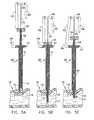
- FIGS. 1A, 1 B and 1 Care an isometric view and two side views, respectively, of a first embodiment of the surgical fastener in accordance with the invention
- FIG. 2is an isometric view of a second embodiment of the surgical fastener in accordance with the invention.
- FIG. 3is a side cutaway view of the second embodiment of the surgical fastener of FIG. 2 in accordance with the invention.
- FIG. 4a side cutaway view of a third embodiment of the surgical fastener in accordance with the invention.
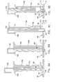
- FIGS. 5A-5Fare front cutaway views of a deployment instrument showing the insertion of the surgical fastener of FIG. 1;
- FIGS. 6A-6Fare front isometric views of another embodiment of a deployment instrument showing the insertion of a surgical fastener
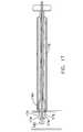
- FIG. 7is a front isometric view of the deployment instrument of FIGS. 5A-5F as it is shipped;
- FIG. 8is a front cutaway view of the deployment instruments of FIGS. 5A-5F and 6 A- 6 F;
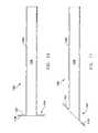
- FIGS. 9A-9Dare side cutaway views showing the use of a deployment instrument with the surgical fastener of FIG. 2;
- FIG. 10is a centerline sectional view of a graft suitable for attachment to an aorta
- FIG. 11is similar to FIG. 10 but illustrative of an alternative embodiment of graft
- FIGS. 12-17are diagrammatic sequential sectional views, illustrating the attachment of a graft to an aorta
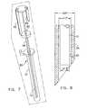
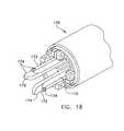
- FIG. 18is an enlarged perspective view of a portion of an instrument used for effecting the attachment of a graft to an aorta;
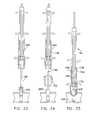
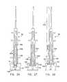
- FIGS. 19-33are diagrammatic sequential sectional views, illustrating an alternative method for attachment of a graft to an aorta
- FIGS. 34-36are perspective views of an alternative embodiment of an instrument for attaching a graft to an aorta
- FIG. 37is a sectional view taken along line 7 — 7 of FIG. 35.
- FIG. 38in a sectional view taken along line 8 — 8 of FIG. 37 .
- Surgical fastenersare shown in FIGS. 1A-4.
- the surgical fasteneris preferably a one piece metal or plastic element appropriately configured during manufacture to hold layers of tissue in compression.
- a needle assemblycomprising a straight tube or needle included in a delivery mechanism is preferably used to hold and deflect the fastener from its final shape into a straight configuration.
- the tubeis either inserted through the tissue or held against the tissue to be joined and the fastener is pushed from the tube until the fastener penetrates the tissue and gradually assumes its original shape, trapping and compressing the layers of tissue 18 between its various elements.
- a superelastic alloy of nickel and titaniumis preferably used to make the fasteners.
- the fasteneris preferably made from a commercial material Nitinol, which is referred to as a “shape memory alloy.”
- Superelasticitycan be conveniently likened to memory. Although forced into a straight line after forming, the superelastic fastener is able to “remember” its former shape and to return to it when no longer constrained within a straight tube.
- Nitinol in superelastic formhas an extremely high elastic limit, which allows large amounts of bending without permanent deformation. In general, Nitinol is capable of strain ratios of up to 8% without experiencing permanent deformation.
- the fasteneris designed to function within the limits of d/2R equal to or less than 0.08, where d is the diameter of the wire and R is the radius to which the wire is formed. It should be noted that the fastener described herein can be made from any material so long as it is adequately elastic. Preferably, the material has superelastic characteristics.
- the preferred embodiment of the fastener 10is essentially that of the body of an extension spring having coils 12 .
- the coils of this fastener 10are spring biased toward each other so that a force F A is required to effect separation of the coils.
- the force at which the coils just begin to separateis the preload value for the fastener. Additional force causes separation of the coils 12 as a function of the gradient of the fastener.
- FIG. 1Clayers of tissue 18 that are trapped between adjacent coils 12 of the fastener will be clamped with a force F 1 being substantially normal to the surface of the tissue 18 and having a value somewhat higher than the preload value of the fastener.
- This forcewhich is a function of fastener material, dimensions and winding technique, is chosen to insure hemostasis when vascular tissue is to be clamped. It should be noted that a compression spring could be used in place of an extension spring so long as the tissue is thick enough that it is compressed between the coils of the fastener once it is in place.
- the theory and practice of winding preloaded coils of metallic wireis routinely practiced in the manufacture of extension springs and is well known to those skilled in the art.
- the fastener of FIGS. 1A-1CWhen the fastener of FIGS. 1A-1C is made of a superelastic material and the strain ratio limitation described above is observed, the fastener can be straightened to penetrate tissue 18 and then released to allow its coils to reform on both the proximate 14 and distal 16 sides of the tissue, thereby clamping the tissue between two coils.
- the number of coils 12is not especially critical. At least two full coils 12 are required and more, such as four coils, are preferable to make placement in the tissue less critical.
- the coils 12preferably have a diameter of ⁇ fraction (3/16) ⁇ to 1 ⁇ 4 of an inch.
- the end of the fastener inside of the bodyrests flush next to the adjacent coil so that the body will not be injured from the fastener end.
- FIGS. 2 and 3show another embodiment of the fastener 20 before and after installation in two layers 14 , 16 of tissue 18 .
- the presence of the tissue layersprevents the fastener from returning completely to its original state.
- the force required to spread the spring biased fastener apart by this amounttherefore also represents the substantially normal compressive force F 2 applied to the layers of tissue 18 .
- That forcewhich is a function of wire diameter and fastener geometry, is chosen by design to achieve homeostasis.
- Those parametersalso determine the gradient or stiffness of the fastener as measured in terms of force F 2 versus deflection of the fastener. Since different tissue thicknesses produce different deflections, and therefore different compressive forces, the gradient must be sufficiently low to maintain reasonable hemostasis over the normal range of tissue thickness without inducing necrosis.
- FIG. 2is an isometric view of the fastener 20 shown schematically in FIG. 3 .
- the lower coil 24penetrates the tissue and curves in a half circle to re-enter the tissue layers.
- the upper coils 22bear on the tissue and tend to trap it inside of the larger lower coil.
- the number of upper coils 22can vary without altering the essential behavior of the fastener 20 .
- two or more coils 22are used to help distribute clamping forces more uniformly about the lower coil, thereby preventing misorientation of the fastener 20 in the tissue 18 .
- the fastener 40 in FIG. 4has symmetrical coils to distribute stress uniformly on both sides of the tissues to be joined.
- the fasteners in FIGS. 2-3 and 4are similar to the fastener in FIGS. 1A-1C in that they are spring biased and use coils to apply pressure.
- the coils in FIGS. 2-3 and 4each have an axis that is oriented substantially transverse to the direction that the fastener takes when it is in a straightened form, whereas the coils in FIGS. 1A-1C each have an have an axis that is substantially transverse to its straightened form.
- the fasteners in FIGS. 1C, 3 and 4all show a fastener clamping two layers of living tissue 18 which include a proximal layer 14 and a distal layer 16 of tissue.
- the fasteners described hereincan fasten any type of materials together, such as a graft or synthetic fibers which may be used as a substitute for tissue, or a combination thereof.
- the synthetic fibersfor example, may be a material such as Gore-Tex, Dacron or Teflon. Autogenous and nonautogenous human tissue, as well as animal tissue, may also be used.
- the leading end 21 of the fastenercan be sharpened for ease of penetration either by cutting the wire on a bias or by tapering the end to a sharp point during manufacture of the fastener.
- the bias cutis commonly used to make sharp points on conventional staples and taper pointing is used to make a certain class of suture needles. Both techniques are well known to those skilled in the art.
- Other sharpening techniques, such as trocar points,may also be effectively applied to the fastener.
- a tube 154 of a delivery instrument 150 that houses the fasteneras shown in FIGS. 5A-5F and 6 A- 6 F, can have a sharpened tip which is used to penetrate the tissue 18 prior to pushing the fastener from said tube. All such variations are referred to herein as “needle assemblies”.
- fastenerscan be designed within the scope of this invention for an equally wide variety of fastening purposes. Some of these shapes are shown in FIGS. 1A-4 and it should be apparent that other variations are both possible and likely as the invention becomes more widely applied.
- the surgical fasteners described hereincan also be used in applications that require the insertion of a fastener from the interior.
- the fastenerscan be used in endovascular procedures to attach a graft within large vessels such as the aorta or iliac arteries to repair aneurysms or occlusions.
- FIGS. 5A-5Fshow a first embodiment of a delivery instrument 50 and the method for inserting the fastener.
- the delivery instrument 50consists of a plunger 52 having a head portion 60 , a needle 54 having a head portion 55 , and a sleeve 51 having a head portion 57 and a stop 56 .
- the plunger 52fits slidingly inside a lumen of the needle 54 , which fits slidingly inside of the sleeve 51 .
- FIGS. 5A-5Fshow the fastener 10 being used to attach a graft (tissue; lower membrane) 16 to a blood vessel having a first layer of tissue 14 and an opposite wall 17 .
- the fasteners described hereincan be used for any layers of material or tissue.
- the delivery instrument 50can deliver any of the fasteners described herein.
- support for the lower membrane 16will be required in order to insert the fastener 10 .
- This normallywill be the rigidity of the body tissue itself or a mechanical support which is provided separately, often as an integral part of the instrument that deploys the graft.
- the head portion 60 of the plunger 52has two stops 62 , 64 attached to it.
- One of the stops 62pivotally engages the head portion 55 of the needle 54 and also pivotally engages a stop 56 of the head portion 57 of the sleeve 51 .
- the other stop 64can engage the head portion 55 of the needle 54 .
- These stops 62 , 64are used to control the amount of depth that the needle and/or fastener may be inserted into the tissue 18 .
- FIG. 5Athe delivery instrument is shown ready to insert a fastener 10 into layers of tissue 18 with the tip of the instrument 50 placed against the tissue.
- the stop 62is engaged against the head portion 55 of the needle 54 , such that the needle 54 and plunger 52 can be inserted into the tissue 18 in unison.
- the needle 54 and plunger 52are inserted until the head portion 55 of the needle 54 rests upon the head portion 57 of the sleeve 51 , as shown in FIG. 5 B. It should be apparent that if the needle 54 is inserted into a blood vessel, as shown in FIGS. 5A-5D, care should be taken not to insert the needle past the opposite wall 17 of the vessel.
- the stop 62is swung to engage the stop 56 on the sleeve 57 . This will enable the needle 54 to be raised while the plunger 52 remains still. While the needle 54 is withdrawn, the restraining force of the needle 54 upon the fastener 10 is removed and the fastener begins to form in its unstressed and undeformed shape.
- the needle 54is raised until its head portion 55 engages stop 64 .
- a doctorcan be certain that the needle has exited the layers of tissue 18 .
- the lower portion of fastener 10will now have formed itself in the shape of a coil.
- the stop 64is swung away from the head portion 55 , such that the needle 54 can be withdrawn fully. As shown, the fastener 10 begins to form in its unstressed shape as the needle 54 is removed.
- FIG. 5Fshows the full withdrawal of the deployment instrument 50 .
- the fastener 10can now fully assume its unstressed shape. It should be noted that the unstressed coils of the fastener 10 shown in FIGS. 5D through 5F are shown having an exaggerated shape for the sake of clarity. The fastener 10 more accurately would appear as shown in FIG. 1C with the coils exerting a compressive pressure upon the layers of tissue 18 .
- FIGS. 6A through 6Fshow a second embodiment of the delivery instrument 100 which can deliver any of the fasteners described herein.
- the plunger 102has a head portion 110 having both a short stop 114 and a long stop 112 attached to it.
- the head portion 105 of the needle 104has two slots 116 and 118 to accept the long 112 and short 114 stops, respectively, at different times of the process.
- the needle 104is slidingly accepted by sleeve. 101 having a head portion 107 .
- the tip of the delivery instrument 100 , fastener 10 and needle 104 for FIGS. 6A-6Fappear the same as in FIGS. 5A-5F, respectively, and are not shown for the sake of clarity.
- the long stop 112is brought into contact with the head portion 105 of the needle 104 .
- the plunger 102 and needle 104are then inserted into the tissue in unison by pushing down in the direction of arrow 120 until the needle's head portion 105 comes into contact with the sleeve's head portion 107 , as shown in FIG. 6 B.
- the needle 104 and fastenerhave penetrated the layers of tissue.
- the head portion 110 of the plunger 102is then rotated as shown in FIG. 6C in the direction of arrow 122 until the long stop 112 can be inserted into slot 116 .
- the needle's head portion 105is then raised in the direction of arrow 124 (FIG. 6D) until the needle's head portion 105 comes into contact with the short stop 114 , as shown in FIG. 6 D.
- the needle 104will be fully withdrawn from the layers of tissue.
- the plunger's head portion 110is rotated in the direction of arrow 126 until the short stop 114 can be inserted into slot 118 .
- the needle's head portion 105is then fully raised in the direction of arrow 128 (FIG. 6F) until the head portion 105 comes into contact with the plunger's head portion 110 .
- the needle 104is now fully retracted from the fastener which should be fastened in the tissue and formed in its unstressed state.
- stopscould be used to position the needle 54 , 104 and plunger 52 , 102 of the delivery instruments 50 , 100 , 150 .
- the needlecould function with only a single stop attached to the shaft of the plunger.
- visual indicatorscould be used, but would be inherently less reliable.
- the delivery instruments as shown in FIGS. 5A-5F and 6 A- 6 Fcould function properly without the short stops 64 , 114 , but not as reliably.
- the delivery instruments, as shown in FIGS. 5A-5F and 6 A- 6 Fcould function without the sleeve 51 or 101 , respectively. It should be apparent that a plurality of any of these delivery instruments described herein could be integrated in a single delivery instrument for sequential or simultaneous delivery of the fastener.
- FIG. 7shows the delivery instrument 50 as it might be shipped from a manufacturer.
- the surgical fastener 10preferably is already inserted and straightened inside of the needle 54 for ease of use.
- the delivery instrument 50can be shipped with or without the sleeve 51 , which can be added later when the fastener is ready to be inserted.
- FIG. 8shows an enlarged view of the needle of either FIGS. 5A-5F or 6 A- 6 F with a fastener inside of it.
- a typical aspect ratio of the length to diameter for this devicecan be in the order of 40 or 50 for less invasive use.
- the diameter of the fasteneris preferably between 0.012 to 0.014 of an inch, more preferably its diameter is 0.013 of an inch, the inside diameter of the lumen 53 of the needle 54 is preferably 0.017 of an inch and the outside diameter of the needle is preferably 0.025 of an inch.
- FIGS. 9A-9Dshow a third embodiment of the delivery instrument 150 and the method for inserting the fastener.
- the third embodiment of the delivery instrument 150is different from the first two embodiments in that a restraining tube 154 is not sharpened to penetrate tissue.
- the surgical fastener 20 used with the deployment instrument 150should have a sharpened end to penetrate tissue.
- the delivery instrument 150consisting of slender tubes and rods, is inherently small in diameter compared to its length.
- FIGS. 9A-9Dare illustrated with a much less favorable aspect ratio for the sake of clarity.
- a typical aspect ratio of the length to diameter for this devicecan be in the order of 40 or 50 for less invasive use.
- FIG. 9Ashows a delivery instrument 150 resting on layers of tissue 18 to be joined.
- the delivery instrument 150restrains a fastener by placing stress upon it.
- the fastener 20which in this example is the fastener of FIG. 1, resides in a substantially straightened form entirely within the restraining tube 154 . It should be apparent that any of the fasteners described herein if given a pointed end 21 can be used with the delivery instrument of FIGS. 9A-9D.
- the pointed end 21 of the fastener 20is facing toward the tissue.
- a plunger 152rests on the fastener 20 and is configured to push the fastener partially out of the restraining tube 154 until the plunger 152 stops against a shield 156 , as shown in FIG. 9 B.
- FIG. 9Bshows the fastener 20 partially installed by the plunger 152 .
- the fastenerpenetrates the proximal 14 and distal 16 layers of tissue and gradually assumes the remembered shape of its lower coil, piercing the distal tissue layer 16 again as it turns upward.
- the lower coil 24 of the fastener 20preferably remains substantially on the distal side of the tissue.
- plunger 152bears on the shield 156 and can progress no further. Depending on the clinical application, it may be necessary to support the tissue 18 distally during penetration.
- FIG. 9Cshows restraining tube 154 moving upward, gradually freeing the fastener 20 to assume its remembered shape. It will obviously not be able to do so until the restraining tube 154 is completely clear, which happens when the restraining tube stops against plunger 152 .
- the restraining tube 154tends to pull the fastener 20 out of the tissue due to friction producing forces exerted by the fastener on the restraining tube as the former tries to assume its remembered shape. This tendency is offset by the plunger 152 bearing on the upper end of the fastener 20 as the restraining tube 154 moves upward.
- FIG. 9Dshows restraining tube 154 in its fully upward position as determined by the plunger 152 .
- the restraining tube 154has cleared the fastener 20 and allowed it to assume its remembered, coiled shape 22 , bearing against the tissue 18 .
- the fastener 20forms within a guide tube 151 , suggesting that the guide tube 151 , properly shaped, may serve to guide the fastener 20 as it forms above the tissue 18 . This may be a useful feature, especially for more complex fasteners which may re-form incorrectly when released from constraint.
- a graft 158 of the type joined to the aortaincludes a body 160 which is typically 10 mm in diameter, and a flange 162 on one end 164 of the body 160 , the flange 162 being formed by altering the weaving, or knitting program, or by molding or stretching the body of the graft, depending on the graft material, which may be synthetic material or natural tissue, including harvested tissue.
- the flange 162which is about 2-21 ⁇ 2 times the body diameter is used to anchor the graft 158 to the inside of the aorta wall 166 .
- the plane of the flange 162is located at an acute angle (FIG.
- the delivery instrument 170 which deploys the graft 158is a device somewhat analogous to an umbrella frame which, when collapsed, supports the graft, suppresses the flange 162 , and transports it through a previously prepared opening in the aorta.
- arms 172 of the tool 170extend, restoring the flange 162 and supporting it during attachment to the aorta wall 166 .
- the arms 172 of the instrument 170retract, allowing the instrument to be retraced axially through the lumen 168 of the graft.
- the aforesaid delivery instrument 170initially resides in the lumen 168 of the graft 158 .
- the flange 162is forced to the diameter of the graft body 160 by pivoting arms 172 which are positioned to enter throughout a hole 176 in the aorta.
- the flange 162 of the graft 158is retained via abutments 174 on the pivoting arms 172 which fit into holes 178 in the flange 162 .
- a retainer 180is positioned to lock the arms 172 in the extended position.
- FIG. 13the graft flange 162 has been pushed into the aorta by the instrument 170 .
- FIG. 14the graft flange 162 is deployed by pivoting the arms 172 of the instrument outward 90°. This is accomplished by releasing the retainer 180 and moving a cam 182 to the left, as viewed in FIG. 14 .
- the cam 182locks the arms 172 in the position shown in FIG. 14 .
- fasteners as described hereinaboveare introduced to attach the flange 162 to the wall of the aorta.
- the force to install the fastenersis countered by the instrument which is pulled to the right, as viewed in FIG. 14, to hold the graft 158 firmly against the wall of the aorta.
- the fastenerscan be applied individually as described hereinabove to minimize the total force applied to the tissue at any time.
- the fastenersare arrayed in a precise relationship to one another and located on the delivery instrument 170 in precise relationship to the flange 162 .
- the fastener deployment meansmay be integral with other operating controls of the delivery instrument.
- FIG. 16after the fasteners 10 have been deployed, cam 182 is released and moved leftward, as viewed in FIG. 16, allowing arms 172 to pivot as the instrument is moved further into the aorta. As this happens, the arms 172 gradually disengage form the holes 178 in the graft flange. In FIG. 16, the retainer 182 moves leftward to fully extend arms 172 (FIG. 17 ).
- the instrumentcan be removed from the graft by pulling to the right, as viewed in FIG. 17 .
- the instrumentwill obviously have a set of ergonomic controls at its proximal end to manipulate the cams and fasteners. These controls can assume a variety of useful forms and can be designed in a variety of ways, all of which are obvious to one skilled in the art and which fall within the scope of this disclosure.
- the above-described devicespermit use of a clinical protocol which minimizes blood loss without clamping the aorta.
- the procedureuses a variety of standard devices in conjunction with the invention to implement the procedure as described hereinabove.
- an exposed artery Ais punctured at the graft site with a needle 184 (18-20 gage), having a removable core (not shown).
- the coreis replaced with a flexible guidewire 190 which is inserted a short distance into the artery A and the needle 184 is removed, leaving the guidewire 190 in place (FIG. 20 ).
- a sheath 192 with hemostatic valve 194is introduced over the guidewire 190 and forced into the artery (FIG. 21 ), dilating the guidewire opening 196 , as required.
- the guidewire 190remains in place.
- a temporary safety balloon catheter 198is inserted over the guidewire 190 and through the sheath 192 (FIG. 22 ). Both the guidewire 190 and the balloon catheter 198 are passed through a central channel in the sheath 192 before placement into the aorta.
- the catheter 198is a dual balloon catheter, with both balloons 200 and 202 preformed and non-compliant.
- the safety balloon 200with a large diameter and short length (40 mm ⁇ 10 mm) when inflated, assumes the shape of a flattened disc (not shown), and is placed at the most distal end of the catheter 198 .
- the dilation balloon 20210 mm in diameter and 80 mm long, assumes a more elliptical shape (FIGS.
- the sheath 192is removed and the dilating balloon 202 is inflated (FIG. 24) to create an arteriotomy, which is a permanent opening in the wall of the aorta approximately 10 mm in diameter to accommodate the graft.
- the delivery instrument 50 with graft 158 as described previously,is inserted into the working sheath 204 .
- the graft 158is then advanced into the aorta A (FIG. 26 ), the graft flange 162 thereof is spread outwardly by the arms 172 (FIG. 27 ), and the fasteners 10 are introduced by the needle or needles 54 (FIGS. 28-31) to effect attachment of the graft 158 to the aorta A (FIGS. 29 and 30 ).
- the needle assemblyis then withdrawn (FIG. 31 ).
- the entire instrumentis withdrawn (FIG. 33 ).
- bloodwould be flowing though the attached graft 198 and a graft occlusion device is necessary.
- the dilation balloon 202would then be inflated (not shown) to occlude the graft body 160 until a standard arterial clamp could be placed externally on the graft to ensure hemostasis.
- the dual balloon catheteris then withdrawn.
- the safety balloon 202is inflated and held against the lumen 168 of the graft body 160 .
- the graftis clamped as the safety balloon is deflated and removed, completing proximal connection of the graft.
- the graftis then extended by anastomosis, if necessary, and routed to its distal destination, using a proximal clamp on the graft to control blood flow during the procedure.
- the delivery instrument 170may be provided with a plunger 210 having a head portion 212 comprising an annular flange 214 having a series of apertures 216 therein.
- sleeve 218 in which the plunger 210 is disposedis provided with an annular flange 220 having apertures 222 therein aligned with the apertures 216 in the flange 214 .
- a further sleeve 224is similarly provided with an annular flange 226 having apertures 228 therein aligned with the apertures 222 of the flange 220 .
- Each series of aligned apertures 216 , 222 , 228retains a needle assembly 230 which includes a needle head 232 having gear teeth 234 thereon.
- Each needle assembly 230(one shown in FIG. 34 ), constitutes a carrier for a suture element 236 and a pusher element 238 for pushing the suture element 236 out of the needle and into the aorta, as described hereinabove.
- Each needle assemblyis provided with an outwardly-extending detent 254 .
- Inlets 240 , 242are provided for admitting fluid to the balloons 200 , 202 (FIGS. 24 and 25 ).
- the plunger 210is provided with a stop detent 244 which is engageable with the flange 220
- the needle assembly 230is provided with a detent 246 disposed in a slot 248 in the sleeve 218 .
- a lever 256extends outwardly through the circle of needle assemblies 230 and is used to effect axial movement of a collar 258 to effect withdrawal of needle assemblies 230 from the graft flange suture area.
- the needle heads 234are disposed in a cap member 250 (FIGS. 35-38) having internal threads 252 which engage the needle head gear teeth 234 .
- turning of the Gap member 250serves to rotate each of the needle assemblies 230 around the axis thereof, to move the needle assembly detents 254 along width-wise portions 248 a of the slots 248 and into length-wise portions 248 b of the slots 248 , which permit lengthwise movement of the needle assemblies 230 .
- FIGS. 34-38permits suturing in a plurality of loci, around the aorta hole 176 and on the graft flange portion 162 , simultaneously, thereby substantially reducing the time required for suturing the graft to the aorta.
- the present inventionmay be used to attach a graft to an aorta, or to attach a graft to some other vascular structure, or to attach a graft to some other tubular structure (e.g., intestine, lymph node, etc.) and in other ways which will be apparent to those skilled in the art.
- tubular structuree.g., intestine, lymph node, etc.
Landscapes
- Health & Medical Sciences (AREA)
- Life Sciences & Earth Sciences (AREA)
- Surgery (AREA)
- Heart & Thoracic Surgery (AREA)
- Engineering & Computer Science (AREA)
- Biomedical Technology (AREA)
- Nuclear Medicine, Radiotherapy & Molecular Imaging (AREA)
- Medical Informatics (AREA)
- Molecular Biology (AREA)
- Animal Behavior & Ethology (AREA)
- General Health & Medical Sciences (AREA)
- Public Health (AREA)
- Veterinary Medicine (AREA)
- Surgical Instruments (AREA)
Abstract
Description
Claims (23)
Priority Applications (2)
| Application Number | Priority Date | Filing Date | Title |
|---|---|---|---|
| US09/944,840US6709442B2 (en) | 2000-09-01 | 2001-08-31 | Vascular bypass grafting instrument and method |
| US10/807,518US20050033318A1 (en) | 2000-09-01 | 2004-03-23 | Vascular bypass grafting instrument and method |
Applications Claiming Priority (2)
| Application Number | Priority Date | Filing Date | Title |
|---|---|---|---|
| US22967500P | 2000-09-01 | 2000-09-01 | |
| US09/944,840US6709442B2 (en) | 2000-09-01 | 2001-08-31 | Vascular bypass grafting instrument and method |
Related Child Applications (1)
| Application Number | Title | Priority Date | Filing Date |
|---|---|---|---|
| US10/807,518ContinuationUS20050033318A1 (en) | 2000-09-01 | 2004-03-23 | Vascular bypass grafting instrument and method |
Publications (2)
| Publication Number | Publication Date |
|---|---|
| US20020065524A1 US20020065524A1 (en) | 2002-05-30 |
| US6709442B2true US6709442B2 (en) | 2004-03-23 |
Family
ID=22862230
Family Applications (2)
| Application Number | Title | Priority Date | Filing Date |
|---|---|---|---|
| US09/944,840Expired - Fee RelatedUS6709442B2 (en) | 2000-09-01 | 2001-08-31 | Vascular bypass grafting instrument and method |
| US10/807,518AbandonedUS20050033318A1 (en) | 2000-09-01 | 2004-03-23 | Vascular bypass grafting instrument and method |
Family Applications After (1)
| Application Number | Title | Priority Date | Filing Date |
|---|---|---|---|
| US10/807,518AbandonedUS20050033318A1 (en) | 2000-09-01 | 2004-03-23 | Vascular bypass grafting instrument and method |
Country Status (5)
| Country | Link |
|---|---|
| US (2) | US6709442B2 (en) |
| EP (1) | EP1331889A1 (en) |
| AU (1) | AU2001288599A1 (en) |
| CA (1) | CA2441874A1 (en) |
| WO (1) | WO2002017796A1 (en) |
Cited By (77)
| Publication number | Priority date | Publication date | Assignee | Title |
|---|---|---|---|---|
| US20020068947A1 (en)* | 2000-10-19 | 2002-06-06 | Kuhns Jesse J. | Surgical instrument having a fastener delivery mechanism |
| US20030120289A1 (en)* | 2001-12-20 | 2003-06-26 | Mcguckin James F | Apparatus and method for treating gastroesophageal reflux disease |
| US20030191481A1 (en)* | 2000-03-31 | 2003-10-09 | John Nguyen | Multiple bias surgical fastener |
| US20040054303A1 (en)* | 2002-07-29 | 2004-03-18 | Taylor Geoffrey L. | Blanching response pressure sore detector apparatus and method |
| US20040050393A1 (en)* | 2002-09-12 | 2004-03-18 | Steve Golden | Anastomosis apparatus and methods |
| US20040133274A1 (en)* | 2002-11-15 | 2004-07-08 | Webler William E. | Cord locking mechanism for use in small systems |
| US20050043708A1 (en)* | 2002-01-31 | 2005-02-24 | Gleeson James B | Anastomosis device and method |
| US6945978B1 (en)* | 2002-11-15 | 2005-09-20 | Advanced Cardiovascular Systems, Inc. | Heart valve catheter |
| US20060030885A1 (en)* | 2002-10-15 | 2006-02-09 | Hyde Gregory M | Apparatuses and methods for heart valve repair |
| US20070073389A1 (en)* | 2001-11-28 | 2007-03-29 | Aptus Endosystems, Inc. | Endovascular aneurysm devices, systems, and methods |
| US7331972B1 (en) | 2002-11-15 | 2008-02-19 | Abbott Cardiovascular Systems Inc. | Heart valve chord cutter |
| US7335213B1 (en) | 2002-11-15 | 2008-02-26 | Abbott Cardiovascular Systems Inc. | Apparatus and methods for heart valve repair |
| US20080125861A1 (en)* | 2002-11-15 | 2008-05-29 | Webler William E | Valve aptation assist device |
| US20080208214A1 (en)* | 2007-02-26 | 2008-08-28 | Olympus Medical Systems Corp. | Applicator and tissue fastening method through natural orifice |
| US20080208217A1 (en)* | 2007-02-26 | 2008-08-28 | Adams Mark L | Hemostatic clip and delivery system |
| US20090069822A1 (en)* | 2007-09-10 | 2009-03-12 | Olympus Medical Systems Corp. | Tissue fastening tool, stent, applicator for placing the same, and tissue fastening method through natural orifice |
| US20090082852A1 (en)* | 2001-06-04 | 2009-03-26 | Aptus Endosystems, Inc. | Catheter-based fastener implantation apparatus and methods |
| US20090099650A1 (en)* | 2001-11-28 | 2009-04-16 | Lee Bolduc | Devices, systems, and methods for endovascular staple and/or prosthesis delivery and implantation |
| US20090118734A1 (en)* | 2005-04-29 | 2009-05-07 | Jmea Corporation | Implantation System for Tissue Repair |
| US7547313B2 (en) | 1998-06-03 | 2009-06-16 | Medtronic, Inc. | Tissue connector apparatus and methods |
| US20090182342A1 (en)* | 2005-04-29 | 2009-07-16 | Jmea Corporation | Disc Annulus Repair System |
| US20100036400A1 (en)* | 2008-08-11 | 2010-02-11 | Aboud Emad T | Vascular anastomosis device |
| US20100102105A1 (en)* | 2007-05-02 | 2010-04-29 | Endogene Pty Ltd | Device and method for delivering shape-memory staples |
| US7722643B2 (en) | 1999-03-01 | 2010-05-25 | Medtronic, Inc. | Tissue connector apparatus and methods |
| US7744611B2 (en) | 2000-10-10 | 2010-06-29 | Medtronic, Inc. | Minimally invasive valve repair procedure and apparatus |
| US20100179570A1 (en)* | 2009-01-13 | 2010-07-15 | Salvatore Privitera | Apparatus and methods for deploying a clip to occlude an anatomical structure |
| US20100185217A1 (en)* | 2007-06-08 | 2010-07-22 | Thomas Hsu | Devices and methods for closure of wounds |
| US7763040B2 (en) | 1998-06-03 | 2010-07-27 | Medtronic, Inc. | Tissue connector apparatus and methods |
| US7879047B2 (en) | 2003-12-10 | 2011-02-01 | Medtronic, Inc. | Surgical connection apparatus and methods |
| US20110071548A1 (en)* | 2009-09-22 | 2011-03-24 | Jmea Corporation | Tissue Repair System |
| US20110087320A1 (en)* | 2001-11-28 | 2011-04-14 | Aptus Endosystems, Inc. | Devices, Systems, and Methods for Prosthesis Delivery and Implantation, Including a Prosthesis Assembly |
| US7938840B2 (en) | 1999-04-05 | 2011-05-10 | Medtronic, Inc. | Apparatus and methods for anastomosis |
| US7963973B2 (en) | 1998-06-03 | 2011-06-21 | Medtronic, Inc. | Multiple loop tissue connector apparatus and methods |
| US7981152B1 (en) | 2004-12-10 | 2011-07-19 | Advanced Cardiovascular Systems, Inc. | Vascular delivery system for accessing and delivering devices into coronary sinus and other vascular sites |
| US7998112B2 (en) | 2003-09-30 | 2011-08-16 | Abbott Cardiovascular Systems Inc. | Deflectable catheter assembly and method of making same |
| US20110238088A1 (en)* | 2001-11-28 | 2011-09-29 | Aptus Endosystems, Inc. | Devices, systems, and methods for supporting tissue and/or structures within a hollow body organ |
| US8029519B2 (en) | 2003-08-22 | 2011-10-04 | Medtronic, Inc. | Eversion apparatus and methods |
| US8105345B2 (en)* | 2002-10-04 | 2012-01-31 | Medtronic, Inc. | Anastomosis apparatus and methods |
| US8118822B2 (en) | 1999-03-01 | 2012-02-21 | Medtronic, Inc. | Bridge clip tissue connector apparatus and methods |
| US8177836B2 (en) | 2008-03-10 | 2012-05-15 | Medtronic, Inc. | Apparatus and methods for minimally invasive valve repair |
| US20120123469A1 (en)* | 2002-03-11 | 2012-05-17 | Wardle John L | Surgical coils and methods of deploying |
| US8187324B2 (en) | 2002-11-15 | 2012-05-29 | Advanced Cardiovascular Systems, Inc. | Telescoping apparatus for delivering and adjusting a medical device in a vessel |
| US8211124B2 (en) | 2003-07-25 | 2012-07-03 | Medtronic, Inc. | Sealing clip, delivery systems, and methods |
| US8317808B2 (en) | 2008-02-18 | 2012-11-27 | Covidien Lp | Device and method for rolling and inserting a prosthetic patch into a body cavity |
| US8328828B2 (en) | 2008-08-11 | 2012-12-11 | Board Of Trustees Of The University Of Arkansas | Device for performing an anastomosis |
| US8394114B2 (en)* | 2003-09-26 | 2013-03-12 | Medtronic, Inc. | Surgical connection apparatus and methods |
| US8398672B2 (en) | 2003-11-12 | 2013-03-19 | Nitinol Devices And Components, Inc. | Method for anchoring a medical device |
| US8518060B2 (en) | 2009-04-09 | 2013-08-27 | Medtronic, Inc. | Medical clip with radial tines, system and method of using same |
| US8529583B1 (en) | 1999-09-03 | 2013-09-10 | Medtronic, Inc. | Surgical clip removal apparatus |
| US20130289584A1 (en)* | 2003-06-26 | 2013-10-31 | Cardica, Inc. | Compliant anastomosis system utilizing suture |
| US8668704B2 (en) | 2009-04-24 | 2014-03-11 | Medtronic, Inc. | Medical clip with tines, system and method of using same |
| US8685044B2 (en) | 2001-11-28 | 2014-04-01 | Aptus Endosystems, Inc. | Systems and methods for attaching a prosthesis with a body lumen or hollow organ |
| US8753359B2 (en) | 2008-02-18 | 2014-06-17 | Covidien Lp | Device and method for deploying and attaching an implant to a biological tissue |
| US8808314B2 (en) | 2008-02-18 | 2014-08-19 | Covidien Lp | Device and method for deploying and attaching an implant to a biological tissue |
| US8888811B2 (en) | 2008-10-20 | 2014-11-18 | Covidien Lp | Device and method for attaching an implant to biological tissue |
| US8906045B2 (en) | 2009-08-17 | 2014-12-09 | Covidien Lp | Articulating patch deployment device and method of use |
| US9005241B2 (en) | 2008-02-18 | 2015-04-14 | Covidien Lp | Means and method for reversibly connecting a patch to a patch deployment device |
| US9034002B2 (en) | 2008-02-18 | 2015-05-19 | Covidien Lp | Lock bar spring and clip for implant deployment device |
| US9044235B2 (en) | 2008-02-18 | 2015-06-02 | Covidien Lp | Magnetic clip for implant deployment device |
| US9149602B2 (en) | 2005-04-22 | 2015-10-06 | Advanced Cardiovascular Systems, Inc. | Dual needle delivery system |
| US9301826B2 (en) | 2008-02-18 | 2016-04-05 | Covidien Lp | Lock bar spring and clip for implant deployment device |
| US9320591B2 (en) | 2001-11-28 | 2016-04-26 | Medtronic Vascular, Inc. | Devices, systems, and methods for prosthesis delivery and implantation, including the use of a fastener tool |
| US9320589B2 (en) | 2001-11-28 | 2016-04-26 | Medtronic Vascular, Inc. | Endovascular aneurysm repair system |
| US9320503B2 (en) | 2001-11-28 | 2016-04-26 | Medtronic Vascular, Inc. | Devices, system, and methods for guiding an operative tool into an interior body region |
| US9393002B2 (en) | 2008-02-18 | 2016-07-19 | Covidien Lp | Clip for implant deployment device |
| US9393093B2 (en) | 2008-02-18 | 2016-07-19 | Covidien Lp | Clip for implant deployment device |
| US9398944B2 (en) | 2008-02-18 | 2016-07-26 | Covidien Lp | Lock bar spring and clip for implant deployment device |
| US9649211B2 (en) | 2009-11-04 | 2017-05-16 | Confluent Medical Technologies, Inc. | Alternating circumferential bridge stent design and methods for use thereof |
| US9833240B2 (en) | 2008-02-18 | 2017-12-05 | Covidien Lp | Lock bar spring and clip for implant deployment device |
| US9999424B2 (en) | 2009-08-17 | 2018-06-19 | Covidien Lp | Means and method for reversibly connecting an implant to a deployment device |
| US10092427B2 (en) | 2009-11-04 | 2018-10-09 | Confluent Medical Technologies, Inc. | Alternating circumferential bridge stent design and methods for use thereof |
| US10182824B2 (en) | 2010-11-11 | 2019-01-22 | Atricure, Inc. | Clip applicator |
| US10194905B2 (en) | 2001-11-28 | 2019-02-05 | Medtronic Vascular, Inc. | Devices, systems, and methods for endovascular staple and/or prosthesis delivery and implantation |
| US10433854B2 (en) | 2010-10-27 | 2019-10-08 | Atricure, Inc. | Appendage clamp deployment assist device |
| US10986982B2 (en) | 2007-06-08 | 2021-04-27 | Medeon Biodesign, Inc. | Lens cover modification |
| US11998211B2 (en) | 2013-11-21 | 2024-06-04 | Atricure, Inc. | Occlusion clip |
| US12004752B2 (en) | 2012-11-21 | 2024-06-11 | Atricure, Inc. | Occlusion clip |
Families Citing this family (32)
| Publication number | Priority date | Publication date | Assignee | Title |
|---|---|---|---|---|
| US20110077672A1 (en)* | 1995-06-07 | 2011-03-31 | Fleischman Sidney D | Devices For Installing Stasis Reducing Means In Body Tissue |
| US10098640B2 (en) | 2001-12-04 | 2018-10-16 | Atricure, Inc. | Left atrial appendage devices and methods |
| DE60336123D1 (en)* | 2002-04-17 | 2011-04-07 | Tyco Healthcare | SPECIFICATIONS INSTRUMENT |
| WO2003088846A1 (en) | 2002-04-22 | 2003-10-30 | Tyco Healthcare Group, Lp | Tack and tack applier |
| FR2843012B1 (en)* | 2002-08-01 | 2005-05-13 | Younes Boudjemline | DEVICE FOR CLOSING SEGMENTED DEFECTS BY NON-SURGICAL METHOD |
| EP1547526A1 (en)* | 2003-12-23 | 2005-06-29 | UMC Utrecht Holding B.V. | Operation element, operation set and method for use thereof |
| US7645285B2 (en)* | 2004-05-26 | 2010-01-12 | Idx Medical, Ltd | Apparatus and methods for occluding a hollow anatomical structure |
| IL164591A0 (en) | 2004-10-14 | 2005-12-18 | Hernia repair device | |
| US8876820B2 (en) | 2004-10-20 | 2014-11-04 | Atricure, Inc. | Surgical clamp |
| US8342376B2 (en)* | 2005-06-10 | 2013-01-01 | Cook Medical Technologies Llc | Medical stapler |
| JP2009501570A (en) | 2005-07-14 | 2009-01-22 | アイディエックス・メディカル・エルティーディー | Apparatus and method for occluding a hollow anatomical structure |
| EP2099385B1 (en) | 2006-11-27 | 2021-02-24 | Davol Inc. | A device especially useful for hernia repair surgeries |
| US8128657B2 (en)* | 2007-02-27 | 2012-03-06 | Olympus Medical Systems Corp. | Suture instrument |
| US8308766B2 (en)* | 2007-02-27 | 2012-11-13 | Olympus Medical Systems Corp. | Endoscopic treatment instrument |
| US20080243141A1 (en) | 2007-04-02 | 2008-10-02 | Salvatore Privitera | Surgical instrument with separate tool head and method of use |
| EP2995276B1 (en) | 2007-10-17 | 2017-07-05 | Davol, Inc. | Fixating means between a mesh and mesh deployment means especially useful for hernia repair surgeries |
| FR2924917B1 (en)* | 2007-12-13 | 2011-02-11 | Microval | APPARATUS FOR INSTALLING SUTURE SPIERS RESULTING FROM A SHAPE MEMORY METAL WIRE. |
| US8920445B2 (en) | 2008-05-07 | 2014-12-30 | Davol, Inc. | Method and apparatus for repairing a hernia |
| WO2010011661A1 (en) | 2008-07-21 | 2010-01-28 | Atricure, Inc. | Apparatus and methods for occluding an anatomical structure |
| CA2744206C (en) | 2008-11-21 | 2019-05-21 | C.R. Bard, Inc. | Soft tissue repair prosthesis, expandable device, and method of soft tissue repair |
| DE102009050457A1 (en)* | 2009-10-23 | 2011-05-05 | Medi-Globe Vascutec Gmbh | A surgical device for passing at least one suture through the edge region of a tissue opening of an individual and method for actuating such device |
| US8080018B2 (en)* | 2010-01-19 | 2011-12-20 | Tyco Healthcare Group Lp | Disposable circumcision device |
| WO2011162287A1 (en) | 2010-06-22 | 2011-12-29 | オリンパスメディカルシステムズ株式会社 | Tissue clamp production method and tissue clamp |
| WO2012047414A1 (en) | 2010-10-05 | 2012-04-12 | C.R. Bard, Inc. | Soft tissue repair prosthesis and expandable device |
| US9066741B2 (en) | 2010-11-01 | 2015-06-30 | Atricure, Inc. | Robotic toolkit |
| RU2559922C1 (en) | 2011-08-15 | 2015-08-20 | Этрикьюэ Инк. | Surgical device |
| US9282973B2 (en) | 2012-01-20 | 2016-03-15 | Atricure, Inc. | Clip deployment tool and associated methods |
| US9510823B2 (en) | 2013-08-02 | 2016-12-06 | Covidien Lp | Devices, systems, and methods for wound closure |
| USD754855S1 (en)* | 2014-11-24 | 2016-04-26 | Ethicon, Inc. | Curved tissue fastening device |
| JP6525668B2 (en)* | 2015-03-27 | 2019-06-05 | テルモ株式会社 | Medical device |
| JP6831264B2 (en)* | 2017-02-23 | 2021-02-17 | テルモ株式会社 | Medical device |
| AU2022272291B2 (en)* | 2021-05-10 | 2025-06-05 | Boston Scientific Scimed, Inc. | Anastomosis device, systems, and methods |
Citations (40)
| Publication number | Priority date | Publication date | Assignee | Title |
|---|---|---|---|---|
| US4366819A (en)* | 1980-11-17 | 1983-01-04 | Kaster Robert L | Anastomotic fitting |
| US4485816A (en) | 1981-06-25 | 1984-12-04 | Alchemia | Shape-memory surgical staple apparatus and method for use in surgical suturing |
| US4665906A (en) | 1983-10-14 | 1987-05-19 | Raychem Corporation | Medical devices incorporating sim alloy elements |
| US4669473A (en) | 1985-09-06 | 1987-06-02 | Acufex Microsurgical, Inc. | Surgical fastener |
| US5002563A (en) | 1990-02-22 | 1991-03-26 | Raychem Corporation | Sutures utilizing shape memory alloys |
| US5067957A (en) | 1983-10-14 | 1991-11-26 | Raychem Corporation | Method of inserting medical devices incorporating SIM alloy elements |
| US5078726A (en) | 1989-02-01 | 1992-01-07 | Kreamer Jeffry W | Graft stent and method of repairing blood vessels |
| US5190546A (en) | 1983-10-14 | 1993-03-02 | Raychem Corporation | Medical devices incorporating SIM alloy elements |
| US5219358A (en) | 1991-08-29 | 1993-06-15 | Ethicon, Inc. | Shape memory effect surgical needles |
| US5258000A (en) | 1991-11-25 | 1993-11-02 | Cook Incorporated | Tissue aperture repair device |
| US5259394A (en) | 1990-12-27 | 1993-11-09 | Ela Medical | Endocardiac lead having an active fastening means |
| US5540701A (en) | 1994-05-20 | 1996-07-30 | Hugh Sharkey | Passive fixation anastomosis method and device |
| US5575800A (en) | 1992-09-04 | 1996-11-19 | Laurus Medical Corporation | Endoscopic suture system |
| US5582616A (en) | 1994-08-05 | 1996-12-10 | Origin Medsystems, Inc. | Surgical helical fastener with applicator |
| US5601572A (en) | 1989-08-16 | 1997-02-11 | Raychem Corporation | Device or apparatus for manipulating matter having a elastic ring clip |
| US5626588A (en) | 1992-04-30 | 1997-05-06 | Lasersurge, Inc. | Trocar wound closure device |
| US5695504A (en)* | 1995-02-24 | 1997-12-09 | Heartport, Inc. | Devices and methods for performing a vascular anastomosis |
| US5782844A (en) | 1996-03-05 | 1998-07-21 | Inbae Yoon | Suture spring device applicator |
| US5810851A (en) | 1996-03-05 | 1998-09-22 | Yoon; Inbae | Suture spring device |
| US5830221A (en) | 1996-09-20 | 1998-11-03 | United States Surgical Corporation | Coil fastener applier |
| US5836955A (en)* | 1995-07-14 | 1998-11-17 | C.R. Bard, Inc. | Wound closure apparatus and method |
| US5843164A (en) | 1994-11-15 | 1998-12-01 | Advanced Carrdiovascular Systems, Inc. | Intraluminal stent for attaching a graft |
| US5868762A (en)* | 1997-09-25 | 1999-02-09 | Sub-Q, Inc. | Percutaneous hemostatic suturing device and method |
| US5944750A (en)* | 1997-06-30 | 1999-08-31 | Eva Corporation | Method and apparatus for the surgical repair of aneurysms |
| US5954732A (en)* | 1997-09-10 | 1999-09-21 | Hart; Charles C. | Suturing apparatus and method |
| US5957940A (en)* | 1997-06-30 | 1999-09-28 | Eva Corporation | Fasteners for use in the surgical repair of aneurysms |
| US5972001A (en) | 1996-11-25 | 1999-10-26 | Yoon; Inbae | Method of ligating anatomical tissue with a suture spring device |
| US5984917A (en) | 1995-06-07 | 1999-11-16 | Ep Technologies, Inc. | Device and method for remote insertion of a closed loop |
| US5997556A (en)* | 1997-06-30 | 1999-12-07 | Eva Corporation | Surgical fastener |
| WO2000016701A1 (en) | 1998-09-18 | 2000-03-30 | United States Surgical Corporation | Endovascular fastener applicator |
| US6113611A (en)* | 1998-05-28 | 2000-09-05 | Advanced Vascular Technologies, Llc | Surgical fastener and delivery system |
| US6193734B1 (en) | 1998-01-23 | 2001-02-27 | Heartport, Inc. | System for performing vascular anastomoses |
| US6254618B1 (en)* | 1995-01-18 | 2001-07-03 | Pepi Dakov | Connector for hollow anatomical organs |
| US6287317B1 (en) | 1997-06-28 | 2001-09-11 | Transvascular, Inc. | Transluminal methods and devices for closing, forming attachments to, and/or forming anastomotic junctions in, luminal anatomical structures |
| US6346111B1 (en) | 1992-09-04 | 2002-02-12 | Scimed Life Systems, Inc. | Suturing instruments and methods of use |
| US20020029048A1 (en)* | 2000-09-01 | 2002-03-07 | Arnold Miller | Endovascular fastener and grafting apparatus and method |
| US6358258B1 (en) | 1999-09-14 | 2002-03-19 | Abbott Laboratories | Device and method for performing end-to-side anastomosis |
| US6416522B1 (en) | 1997-07-24 | 2002-07-09 | Ernst Peter Strecker | Intraluminal implantation device |
| US6416535B1 (en)* | 1987-04-06 | 2002-07-09 | Endovascular Technologies, Inc. | Artificial graft and implantation method |
| US20030033005A1 (en)* | 1998-06-10 | 2003-02-13 | Russell A. Houser | Aortic aneurysm treatment systems |
- 2001
- 2001-08-31USUS09/944,840patent/US6709442B2/ennot_activeExpired - Fee Related
- 2001-08-31CACA002441874Apatent/CA2441874A1/ennot_activeAbandoned
- 2001-08-31WOPCT/US2001/027185patent/WO2002017796A1/ennot_activeApplication Discontinuation
- 2001-08-31EPEP01968347Apatent/EP1331889A1/ennot_activeWithdrawn
- 2001-08-31AUAU2001288599Apatent/AU2001288599A1/ennot_activeAbandoned
- 2004
- 2004-03-23USUS10/807,518patent/US20050033318A1/ennot_activeAbandoned
Patent Citations (46)
| Publication number | Priority date | Publication date | Assignee | Title |
|---|---|---|---|---|
| US4366819A (en)* | 1980-11-17 | 1983-01-04 | Kaster Robert L | Anastomotic fitting |
| US4485816A (en) | 1981-06-25 | 1984-12-04 | Alchemia | Shape-memory surgical staple apparatus and method for use in surgical suturing |
| US5597378A (en) | 1983-10-14 | 1997-01-28 | Raychem Corporation | Medical devices incorporating SIM alloy elements |
| US4665906A (en) | 1983-10-14 | 1987-05-19 | Raychem Corporation | Medical devices incorporating sim alloy elements |
| US6306141B1 (en) | 1983-10-14 | 2001-10-23 | Medtronic, Inc. | Medical devices incorporating SIM alloy elements |
| US5067957A (en) | 1983-10-14 | 1991-11-26 | Raychem Corporation | Method of inserting medical devices incorporating SIM alloy elements |
| US5190546A (en) | 1983-10-14 | 1993-03-02 | Raychem Corporation | Medical devices incorporating SIM alloy elements |
| US4669473A (en) | 1985-09-06 | 1987-06-02 | Acufex Microsurgical, Inc. | Surgical fastener |
| US6416535B1 (en)* | 1987-04-06 | 2002-07-09 | Endovascular Technologies, Inc. | Artificial graft and implantation method |
| US5078726A (en) | 1989-02-01 | 1992-01-07 | Kreamer Jeffry W | Graft stent and method of repairing blood vessels |
| US5601572A (en) | 1989-08-16 | 1997-02-11 | Raychem Corporation | Device or apparatus for manipulating matter having a elastic ring clip |
| US5002563A (en) | 1990-02-22 | 1991-03-26 | Raychem Corporation | Sutures utilizing shape memory alloys |
| US5259394A (en) | 1990-12-27 | 1993-11-09 | Ela Medical | Endocardiac lead having an active fastening means |
| US5219358A (en) | 1991-08-29 | 1993-06-15 | Ethicon, Inc. | Shape memory effect surgical needles |
| US5258000A (en) | 1991-11-25 | 1993-11-02 | Cook Incorporated | Tissue aperture repair device |
| US5626588A (en) | 1992-04-30 | 1997-05-06 | Lasersurge, Inc. | Trocar wound closure device |
| US6346111B1 (en) | 1992-09-04 | 2002-02-12 | Scimed Life Systems, Inc. | Suturing instruments and methods of use |
| US5575800A (en) | 1992-09-04 | 1996-11-19 | Laurus Medical Corporation | Endoscopic suture system |
| US5540701A (en) | 1994-05-20 | 1996-07-30 | Hugh Sharkey | Passive fixation anastomosis method and device |
| US5582616A (en) | 1994-08-05 | 1996-12-10 | Origin Medsystems, Inc. | Surgical helical fastener with applicator |
| US5810882A (en) | 1994-08-05 | 1998-09-22 | Origin Medsystems, Inc. | Surgical helical fastener with applicator and method of use |
| US5843164A (en) | 1994-11-15 | 1998-12-01 | Advanced Carrdiovascular Systems, Inc. | Intraluminal stent for attaching a graft |
| US6254618B1 (en)* | 1995-01-18 | 2001-07-03 | Pepi Dakov | Connector for hollow anatomical organs |
| US5695504A (en)* | 1995-02-24 | 1997-12-09 | Heartport, Inc. | Devices and methods for performing a vascular anastomosis |
| US6132438A (en) | 1995-06-07 | 2000-10-17 | Ep Technologies, Inc. | Devices for installing stasis reducing means in body tissue |
| US6379366B1 (en) | 1995-06-07 | 2002-04-30 | Ep Technologies, Inc. | Devices for installing stasis reducing means in body tissue |
| US5984917A (en) | 1995-06-07 | 1999-11-16 | Ep Technologies, Inc. | Device and method for remote insertion of a closed loop |
| US5836955A (en)* | 1995-07-14 | 1998-11-17 | C.R. Bard, Inc. | Wound closure apparatus and method |
| US5782844A (en) | 1996-03-05 | 1998-07-21 | Inbae Yoon | Suture spring device applicator |
| US5810851A (en) | 1996-03-05 | 1998-09-22 | Yoon; Inbae | Suture spring device |
| US5830221A (en) | 1996-09-20 | 1998-11-03 | United States Surgical Corporation | Coil fastener applier |
| US5972001A (en) | 1996-11-25 | 1999-10-26 | Yoon; Inbae | Method of ligating anatomical tissue with a suture spring device |
| US6287317B1 (en) | 1997-06-28 | 2001-09-11 | Transvascular, Inc. | Transluminal methods and devices for closing, forming attachments to, and/or forming anastomotic junctions in, luminal anatomical structures |
| US5997556A (en)* | 1997-06-30 | 1999-12-07 | Eva Corporation | Surgical fastener |
| US5944750A (en)* | 1997-06-30 | 1999-08-31 | Eva Corporation | Method and apparatus for the surgical repair of aneurysms |
| US5957940A (en)* | 1997-06-30 | 1999-09-28 | Eva Corporation | Fasteners for use in the surgical repair of aneurysms |
| US6416522B1 (en) | 1997-07-24 | 2002-07-09 | Ernst Peter Strecker | Intraluminal implantation device |
| US5954732A (en)* | 1997-09-10 | 1999-09-21 | Hart; Charles C. | Suturing apparatus and method |
| US5868762A (en)* | 1997-09-25 | 1999-02-09 | Sub-Q, Inc. | Percutaneous hemostatic suturing device and method |
| US6193734B1 (en) | 1998-01-23 | 2001-02-27 | Heartport, Inc. | System for performing vascular anastomoses |
| US6113611A (en)* | 1998-05-28 | 2000-09-05 | Advanced Vascular Technologies, Llc | Surgical fastener and delivery system |
| US20030033005A1 (en)* | 1998-06-10 | 2003-02-13 | Russell A. Houser | Aortic aneurysm treatment systems |
| WO2000016701A1 (en) | 1998-09-18 | 2000-03-30 | United States Surgical Corporation | Endovascular fastener applicator |
| US6592593B1 (en)* | 1998-09-18 | 2003-07-15 | United States Surgical Corporation | Endovascular fastener applicator |
| US6358258B1 (en) | 1999-09-14 | 2002-03-19 | Abbott Laboratories | Device and method for performing end-to-side anastomosis |
| US20020029048A1 (en)* | 2000-09-01 | 2002-03-07 | Arnold Miller | Endovascular fastener and grafting apparatus and method |
Cited By (150)
| Publication number | Priority date | Publication date | Assignee | Title |
|---|---|---|---|---|
| US7963973B2 (en) | 1998-06-03 | 2011-06-21 | Medtronic, Inc. | Multiple loop tissue connector apparatus and methods |
| US7547313B2 (en) | 1998-06-03 | 2009-06-16 | Medtronic, Inc. | Tissue connector apparatus and methods |
| US7763040B2 (en) | 1998-06-03 | 2010-07-27 | Medtronic, Inc. | Tissue connector apparatus and methods |
| US7722643B2 (en) | 1999-03-01 | 2010-05-25 | Medtronic, Inc. | Tissue connector apparatus and methods |
| US8118822B2 (en) | 1999-03-01 | 2012-02-21 | Medtronic, Inc. | Bridge clip tissue connector apparatus and methods |
| US8353921B2 (en) | 1999-03-01 | 2013-01-15 | Medtronic, Inc | Tissue connector apparatus and methods |
| US7892255B2 (en) | 1999-03-01 | 2011-02-22 | Medtronic, Inc. | Tissue connector apparatus and methods |
| US7938840B2 (en) | 1999-04-05 | 2011-05-10 | Medtronic, Inc. | Apparatus and methods for anastomosis |
| US8211131B2 (en) | 1999-04-05 | 2012-07-03 | Medtronic, Inc. | Apparatus and methods for anastomosis |
| US8529583B1 (en) | 1999-09-03 | 2013-09-10 | Medtronic, Inc. | Surgical clip removal apparatus |
| US20030191481A1 (en)* | 2000-03-31 | 2003-10-09 | John Nguyen | Multiple bias surgical fastener |
| US8353092B2 (en) | 2000-03-31 | 2013-01-15 | Medtronic, Inc. | Multiple bias surgical fastener |
| US7896892B2 (en) | 2000-03-31 | 2011-03-01 | Medtronic, Inc. | Multiple bias surgical fastener |
| US7744611B2 (en) | 2000-10-10 | 2010-06-29 | Medtronic, Inc. | Minimally invasive valve repair procedure and apparatus |
| US7914544B2 (en) | 2000-10-10 | 2011-03-29 | Medtronic, Inc. | Minimally invasive valve repair procedure and apparatus |
| US7905893B2 (en) | 2000-10-19 | 2011-03-15 | Ethicon Endo-Surgery, Inc. | Method for delivering a plurality of fasteners |
| US20080243143A1 (en)* | 2000-10-19 | 2008-10-02 | Kuhns Jesse J | Surgical instrument having a fastener delivery mechanism |
| US20020068947A1 (en)* | 2000-10-19 | 2002-06-06 | Kuhns Jesse J. | Surgical instrument having a fastener delivery mechanism |
| US20080045978A1 (en)* | 2000-10-19 | 2008-02-21 | Kuhns Jesse J | Method For Delivering a Plurality of Fasteners |
| US7485124B2 (en)* | 2000-10-19 | 2009-02-03 | Ethicon Endo-Surgery, Inc. | Surgical instrument having a fastener delivery mechanism |
| US9968353B2 (en) | 2001-06-04 | 2018-05-15 | Medtronic Vascular, Inc. | Catheter based fastener implantation apparatus and methods |
| US20090082852A1 (en)* | 2001-06-04 | 2009-03-26 | Aptus Endosystems, Inc. | Catheter-based fastener implantation apparatus and methods |
| US9744021B2 (en) | 2001-11-28 | 2017-08-29 | Medtronic Vascular, Inc. | Devices, systems, and methods for prosthesis delivery and implantation, including the use of a fastener tool |
| US9320591B2 (en) | 2001-11-28 | 2016-04-26 | Medtronic Vascular, Inc. | Devices, systems, and methods for prosthesis delivery and implantation, including the use of a fastener tool |
| US10595867B2 (en) | 2001-11-28 | 2020-03-24 | Medtronic Vascular, Inc. | Systems and methods for attaching a prosthesis within a body lumen or hollow organ |
| US10357230B2 (en) | 2001-11-28 | 2019-07-23 | Medtronic Vascular, Inc. | Devices, system, and methods for guiding an operative tool into an interior body region |
| US10299791B2 (en) | 2001-11-28 | 2019-05-28 | Medtronic Vascular, Inc. | Endovascular aneurysm repair system |
| US9023065B2 (en) | 2001-11-28 | 2015-05-05 | Aptus Endosystems, Inc. | Devices, systems, and methods for supporting tissue and/or structures within a hollow body organ |
| US20090099650A1 (en)* | 2001-11-28 | 2009-04-16 | Lee Bolduc | Devices, systems, and methods for endovascular staple and/or prosthesis delivery and implantation |
| US20090112303A1 (en)* | 2001-11-28 | 2009-04-30 | Lee Bolduc | Devices, systems, and methods for endovascular staple and/or prosthesis delivery and implantation |
| US10194905B2 (en) | 2001-11-28 | 2019-02-05 | Medtronic Vascular, Inc. | Devices, systems, and methods for endovascular staple and/or prosthesis delivery and implantation |
| US20070073389A1 (en)* | 2001-11-28 | 2007-03-29 | Aptus Endosystems, Inc. | Endovascular aneurysm devices, systems, and methods |
| US10098770B2 (en) | 2001-11-28 | 2018-10-16 | Medtronic Vascular, Inc. | Endovascular aneurysm devices, systems, and methods |
| US20110087320A1 (en)* | 2001-11-28 | 2011-04-14 | Aptus Endosystems, Inc. | Devices, Systems, and Methods for Prosthesis Delivery and Implantation, Including a Prosthesis Assembly |
| US9808250B2 (en) | 2001-11-28 | 2017-11-07 | Medtronic Vascular, Inc. | Systems and methods for attaching a prosthesis within a body lumen or hollow organ |
| US8685044B2 (en) | 2001-11-28 | 2014-04-01 | Aptus Endosystems, Inc. | Systems and methods for attaching a prosthesis with a body lumen or hollow organ |
| US20110238088A1 (en)* | 2001-11-28 | 2011-09-29 | Aptus Endosystems, Inc. | Devices, systems, and methods for supporting tissue and/or structures within a hollow body organ |
| US9320589B2 (en) | 2001-11-28 | 2016-04-26 | Medtronic Vascular, Inc. | Endovascular aneurysm repair system |
| US9320503B2 (en) | 2001-11-28 | 2016-04-26 | Medtronic Vascular, Inc. | Devices, system, and methods for guiding an operative tool into an interior body region |
| US7261722B2 (en)* | 2001-12-20 | 2007-08-28 | Rex Medical, L.P. | Apparatus and method for treating gastroesophageal reflux disease |
| US20070270886A1 (en)* | 2001-12-20 | 2007-11-22 | Rex Medical | Apparatus and method for treating gastroesophageal reflux disease |
| US20030120289A1 (en)* | 2001-12-20 | 2003-06-26 | Mcguckin James F | Apparatus and method for treating gastroesophageal reflux disease |
| US20050043708A1 (en)* | 2002-01-31 | 2005-02-24 | Gleeson James B | Anastomosis device and method |
| US20120123469A1 (en)* | 2002-03-11 | 2012-05-17 | Wardle John L | Surgical coils and methods of deploying |
| US9301756B2 (en)* | 2002-03-11 | 2016-04-05 | John L. Wardle | Surgical coils and methods of deploying |
| US20040054303A1 (en)* | 2002-07-29 | 2004-03-18 | Taylor Geoffrey L. | Blanching response pressure sore detector apparatus and method |
| US8066724B2 (en)* | 2002-09-12 | 2011-11-29 | Medtronic, Inc. | Anastomosis apparatus and methods |
| US20040050393A1 (en)* | 2002-09-12 | 2004-03-18 | Steve Golden | Anastomosis apparatus and methods |
| US7976556B2 (en) | 2002-09-12 | 2011-07-12 | Medtronic, Inc. | Anastomosis apparatus and methods |
| US8105345B2 (en)* | 2002-10-04 | 2012-01-31 | Medtronic, Inc. | Anastomosis apparatus and methods |
| US8298251B2 (en) | 2002-10-04 | 2012-10-30 | Medtronic, Inc. | Anastomosis apparatus and methods |
| US20060030885A1 (en)* | 2002-10-15 | 2006-02-09 | Hyde Gregory M | Apparatuses and methods for heart valve repair |
| US20100222876A1 (en)* | 2002-10-15 | 2010-09-02 | Abbott Cardiovascular Systems Inc. | Apparatuses and methods for heart valve repair |
| US8133272B2 (en) | 2002-10-15 | 2012-03-13 | Advanced Cardiovascular Systems, Inc. | Apparatuses and methods for heart valve repair |
| US7740638B2 (en) | 2002-10-15 | 2010-06-22 | Abbott Cardiovascular Systems Inc. | Apparatuses and methods for heart valve repair |
| US20070050019A1 (en)* | 2002-10-15 | 2007-03-01 | Hyde Gregory M | Apparatuses and methods for heart valve repair |
| US7087064B1 (en) | 2002-10-15 | 2006-08-08 | Advanced Cardiovascular Systems, Inc. | Apparatuses and methods for heart valve repair |
| US6945978B1 (en)* | 2002-11-15 | 2005-09-20 | Advanced Cardiovascular Systems, Inc. | Heart valve catheter |
| US7942928B2 (en) | 2002-11-15 | 2011-05-17 | Advanced Cardiovascular Systems, Inc. | Valve aptation assist device |
| US20110184512A1 (en)* | 2002-11-15 | 2011-07-28 | Webler William E | Valve aptation assist device |
| US8579967B2 (en) | 2002-11-15 | 2013-11-12 | Advanced Cardiovascular Systems, Inc. | Valve aptation assist device |
| US7485143B2 (en) | 2002-11-15 | 2009-02-03 | Abbott Cardiovascular Systems Inc. | Apparatuses and methods for heart valve repair |
| US7927370B2 (en) | 2002-11-15 | 2011-04-19 | Advanced Cardiovascular Systems, Inc. | Valve aptation assist device |
| US20050038506A1 (en)* | 2002-11-15 | 2005-02-17 | Webler William E. | Apparatuses and methods for heart valve repair |
| US20070123978A1 (en)* | 2002-11-15 | 2007-05-31 | Cox Daniel L | Apparatuses and methods for heart valve repair |
| US7828819B2 (en) | 2002-11-15 | 2010-11-09 | Advanced Cardiovascular Systems, Inc. | Cord locking mechanism for use in small systems |
| US20040133274A1 (en)* | 2002-11-15 | 2004-07-08 | Webler William E. | Cord locking mechanism for use in small systems |
| US8070804B2 (en) | 2002-11-15 | 2011-12-06 | Abbott Cardiovascular Systems Inc. | Apparatus and methods for heart valve repair |
| US7331972B1 (en) | 2002-11-15 | 2008-02-19 | Abbott Cardiovascular Systems Inc. | Heart valve chord cutter |
| US7914577B2 (en) | 2002-11-15 | 2011-03-29 | Advanced Cardiovascular Systems, Inc. | Apparatuses and methods for heart valve repair |
| US7335213B1 (en) | 2002-11-15 | 2008-02-26 | Abbott Cardiovascular Systems Inc. | Apparatus and methods for heart valve repair |
| US20080125861A1 (en)* | 2002-11-15 | 2008-05-29 | Webler William E | Valve aptation assist device |
| US7404824B1 (en) | 2002-11-15 | 2008-07-29 | Advanced Cardiovascular Systems, Inc. | Valve aptation assist device |
| US8187324B2 (en) | 2002-11-15 | 2012-05-29 | Advanced Cardiovascular Systems, Inc. | Telescoping apparatus for delivering and adjusting a medical device in a vessel |
| US20130289584A1 (en)* | 2003-06-26 | 2013-10-31 | Cardica, Inc. | Compliant anastomosis system utilizing suture |
| US8211124B2 (en) | 2003-07-25 | 2012-07-03 | Medtronic, Inc. | Sealing clip, delivery systems, and methods |
| US8029519B2 (en) | 2003-08-22 | 2011-10-04 | Medtronic, Inc. | Eversion apparatus and methods |
| US8394114B2 (en)* | 2003-09-26 | 2013-03-12 | Medtronic, Inc. | Surgical connection apparatus and methods |
| US7998112B2 (en) | 2003-09-30 | 2011-08-16 | Abbott Cardiovascular Systems Inc. | Deflectable catheter assembly and method of making same |
| US8016784B1 (en) | 2003-09-30 | 2011-09-13 | Abbott Cardiovascular Systems Inc. | Deflectable catheter assembly having compression compensation mechanism |
| US9283065B2 (en) | 2003-11-12 | 2016-03-15 | Nitinol Devices And Components, Inc. | Medical device anchor and delivery system |
| US8398672B2 (en) | 2003-11-12 | 2013-03-19 | Nitinol Devices And Components, Inc. | Method for anchoring a medical device |
| US8409239B2 (en) | 2003-11-12 | 2013-04-02 | Nitinol Devices And Components, Inc. | Medical device anchor and delivery system |
| US7879047B2 (en) | 2003-12-10 | 2011-02-01 | Medtronic, Inc. | Surgical connection apparatus and methods |
| US7981152B1 (en) | 2004-12-10 | 2011-07-19 | Advanced Cardiovascular Systems, Inc. | Vascular delivery system for accessing and delivering devices into coronary sinus and other vascular sites |
| US9950144B2 (en) | 2005-04-22 | 2018-04-24 | Advanced Cardiovascular Systems, Inc. | Dual needle delivery system |
| US9149602B2 (en) | 2005-04-22 | 2015-10-06 | Advanced Cardiovascular Systems, Inc. | Dual needle delivery system |
| US8702718B2 (en) | 2005-04-29 | 2014-04-22 | Jmea Corporation | Implantation system for tissue repair |
| US8961530B2 (en) | 2005-04-29 | 2015-02-24 | Jmea Corporation | Implantation system for tissue repair |
| US8070818B2 (en) | 2005-04-29 | 2011-12-06 | Jmea Corporation | Disc annulus repair system |
| US8177847B2 (en) | 2005-04-29 | 2012-05-15 | Jmea Corporation | Disc repair system |
| US8317868B2 (en) | 2005-04-29 | 2012-11-27 | Jmea Corporation | Disc repair system |
| US20100057145A1 (en)* | 2005-04-29 | 2010-03-04 | Jmea Corporation | Disc Repair System |
| US20090182342A1 (en)* | 2005-04-29 | 2009-07-16 | Jmea Corporation | Disc Annulus Repair System |
| US20090118734A1 (en)* | 2005-04-29 | 2009-05-07 | Jmea Corporation | Implantation System for Tissue Repair |
| US20080208214A1 (en)* | 2007-02-26 | 2008-08-28 | Olympus Medical Systems Corp. | Applicator and tissue fastening method through natural orifice |
| US9510833B2 (en) | 2007-02-26 | 2016-12-06 | Olympus Corporation | Applicator and tissue fastening method through natural orifice |
| US20110152886A1 (en)* | 2007-02-26 | 2011-06-23 | Olympus Medical Systems Corp. | Applicator and tissue fastening method through natural orifice |
| US20080208217A1 (en)* | 2007-02-26 | 2008-08-28 | Adams Mark L | Hemostatic clip and delivery system |
| US8845658B2 (en)* | 2007-02-26 | 2014-09-30 | Boston Scientific Scimed, Inc. | Hemostatic clip and delivery system |
| US8220689B2 (en)* | 2007-05-02 | 2012-07-17 | Endogene Pty Ltd | Device and method for delivering shape-memory staples |
| US20100102105A1 (en)* | 2007-05-02 | 2010-04-29 | Endogene Pty Ltd | Device and method for delivering shape-memory staples |
| US9022272B2 (en) | 2007-05-02 | 2015-05-05 | Endogene Limited | Device and method for delivering shape-memory staples |
| US8752750B2 (en) | 2007-05-02 | 2014-06-17 | Endogene Limited | Device and method for delivering shape-memory staples |
| US10986982B2 (en) | 2007-06-08 | 2021-04-27 | Medeon Biodesign, Inc. | Lens cover modification |
| US10314566B2 (en) | 2007-06-08 | 2019-06-11 | Medeon Biodesign, Inc. | Devices and methods for closure of wounds |
| US20100185217A1 (en)* | 2007-06-08 | 2010-07-22 | Thomas Hsu | Devices and methods for closure of wounds |
| US9241613B2 (en)* | 2007-06-08 | 2016-01-26 | Medeon Biodesign, Inc. | Devices and methods for closure of wounds |
| US20090069822A1 (en)* | 2007-09-10 | 2009-03-12 | Olympus Medical Systems Corp. | Tissue fastening tool, stent, applicator for placing the same, and tissue fastening method through natural orifice |
| US8858576B2 (en)* | 2007-09-10 | 2014-10-14 | Olympus Medical Systems Corp. | Tissue fastening tool, stent, applicator for placing the same, and tissue fastening method through natural orifice |
| US9393002B2 (en) | 2008-02-18 | 2016-07-19 | Covidien Lp | Clip for implant deployment device |
| US10182898B2 (en) | 2008-02-18 | 2019-01-22 | Covidien Lp | Clip for implant deployment device |
| US10695155B2 (en) | 2008-02-18 | 2020-06-30 | Covidien Lp | Device and method for deploying and attaching an implant to a biological tissue |
| US8317808B2 (en) | 2008-02-18 | 2012-11-27 | Covidien Lp | Device and method for rolling and inserting a prosthetic patch into a body cavity |
| US9833240B2 (en) | 2008-02-18 | 2017-12-05 | Covidien Lp | Lock bar spring and clip for implant deployment device |
| US9301826B2 (en) | 2008-02-18 | 2016-04-05 | Covidien Lp | Lock bar spring and clip for implant deployment device |
| US8808314B2 (en) | 2008-02-18 | 2014-08-19 | Covidien Lp | Device and method for deploying and attaching an implant to a biological tissue |
| US9044235B2 (en) | 2008-02-18 | 2015-06-02 | Covidien Lp | Magnetic clip for implant deployment device |
| US8753359B2 (en) | 2008-02-18 | 2014-06-17 | Covidien Lp | Device and method for deploying and attaching an implant to a biological tissue |
| US9005241B2 (en) | 2008-02-18 | 2015-04-14 | Covidien Lp | Means and method for reversibly connecting a patch to a patch deployment device |
| US9107726B2 (en) | 2008-02-18 | 2015-08-18 | Covidien Lp | Device and method for deploying and attaching an implant to a biological tissue |
| US9393093B2 (en) | 2008-02-18 | 2016-07-19 | Covidien Lp | Clip for implant deployment device |
| US9398944B2 (en) | 2008-02-18 | 2016-07-26 | Covidien Lp | Lock bar spring and clip for implant deployment device |
| US9034002B2 (en) | 2008-02-18 | 2015-05-19 | Covidien Lp | Lock bar spring and clip for implant deployment device |
| US10159554B2 (en) | 2008-02-18 | 2018-12-25 | Covidien Lp | Clip for implant deployment device |
| US8177836B2 (en) | 2008-03-10 | 2012-05-15 | Medtronic, Inc. | Apparatus and methods for minimally invasive valve repair |
| US20100036400A1 (en)* | 2008-08-11 | 2010-02-11 | Aboud Emad T | Vascular anastomosis device |
| US8328828B2 (en) | 2008-08-11 | 2012-12-11 | Board Of Trustees Of The University Of Arkansas | Device for performing an anastomosis |
| US8888811B2 (en) | 2008-10-20 | 2014-11-18 | Covidien Lp | Device and method for attaching an implant to biological tissue |
| US9393023B2 (en) | 2009-01-13 | 2016-07-19 | Atricure, Inc. | Apparatus and methods for deploying a clip to occlude an anatomical structure |
| US20100179570A1 (en)* | 2009-01-13 | 2010-07-15 | Salvatore Privitera | Apparatus and methods for deploying a clip to occlude an anatomical structure |
| US8734473B2 (en) | 2009-02-18 | 2014-05-27 | Covidien Lp | Device and method for rolling and inserting a prosthetic patch into a body cavity |
| US9066719B2 (en) | 2009-03-23 | 2015-06-30 | Endogene Limited | Device and method for delivering shape-memory staples |
| US8518060B2 (en) | 2009-04-09 | 2013-08-27 | Medtronic, Inc. | Medical clip with radial tines, system and method of using same |
| US8668704B2 (en) | 2009-04-24 | 2014-03-11 | Medtronic, Inc. | Medical clip with tines, system and method of using same |
| US8906045B2 (en) | 2009-08-17 | 2014-12-09 | Covidien Lp | Articulating patch deployment device and method of use |
| US9999424B2 (en) | 2009-08-17 | 2018-06-19 | Covidien Lp | Means and method for reversibly connecting an implant to a deployment device |
| US8603118B2 (en) | 2009-09-22 | 2013-12-10 | Jmea Corporation | Tissue repair system |
| US8211126B2 (en) | 2009-09-22 | 2012-07-03 | Jmea Corporation | Tissue repair system |
| US20110071548A1 (en)* | 2009-09-22 | 2011-03-24 | Jmea Corporation | Tissue Repair System |
| US10092427B2 (en) | 2009-11-04 | 2018-10-09 | Confluent Medical Technologies, Inc. | Alternating circumferential bridge stent design and methods for use thereof |
| US9649211B2 (en) | 2009-11-04 | 2017-05-16 | Confluent Medical Technologies, Inc. | Alternating circumferential bridge stent design and methods for use thereof |
| US10433854B2 (en) | 2010-10-27 | 2019-10-08 | Atricure, Inc. | Appendage clamp deployment assist device |
| US11883035B2 (en) | 2010-10-27 | 2024-01-30 | Atricure, Inc. | Appendage clamp deployment assist device |
| US10182824B2 (en) | 2010-11-11 | 2019-01-22 | Atricure, Inc. | Clip applicator |
| US12004752B2 (en) | 2012-11-21 | 2024-06-11 | Atricure, Inc. | Occlusion clip |
| US12193680B2 (en) | 2012-11-21 | 2025-01-14 | Atricure, Inc. | Occlusion clip |
| US11998211B2 (en) | 2013-11-21 | 2024-06-04 | Atricure, Inc. | Occlusion clip |
| US11998212B2 (en) | 2013-11-21 | 2024-06-04 | Atricure, Inc. | Occlusion clip |
| US12076019B2 (en) | 2013-11-21 | 2024-09-03 | Atricure, Inc. | Occlusion clip |
Also Published As
| Publication number | Publication date |
|---|---|
| CA2441874A1 (en) | 2002-03-07 |
| US20050033318A1 (en) | 2005-02-10 |
| EP1331889A1 (en) | 2003-08-06 |
| AU2001288599A1 (en) | 2002-03-13 |
| WO2002017796A1 (en) | 2002-03-07 |
| US20020065524A1 (en) | 2002-05-30 |
Similar Documents
| Publication | Publication Date | Title |
|---|---|---|
| US6709442B2 (en) | Vascular bypass grafting instrument and method | |
| US6837893B2 (en) | Multi-fastener surgical apparatus and method | |
| US6113611A (en) | Surgical fastener and delivery system | |
| US20020029048A1 (en) | Endovascular fastener and grafting apparatus and method | |
| US9301756B2 (en) | Surgical coils and methods of deploying | |
| US20040073237A1 (en) | Surgical fastener and delivery system | |
| US8211131B2 (en) | Apparatus and methods for anastomosis | |
| US8226670B2 (en) | Apparatus and method for connecting a conduit to a hollow organ | |
| US6183486B1 (en) | Device and method for minimizing heart displacements during a beating heart surgical procedure | |
| US8105345B2 (en) | Anastomosis apparatus and methods | |
| JP2020032288A (en) | Suturing devices and methods for closing patent foramen ovale | |
| US20070043385A1 (en) | Suturing device and method | |
| JP2002518082A (en) | Sutureless anastomosis system | |
| JP2008500125A (en) | Suture device | |
| WO1998042262A1 (en) | Device and method for suturing tissue | |
| WO1998002099A9 (en) | Coronary shunt and method of use | |
| GB2581863A (en) | Device for heart repair |
Legal Events
| Date | Code | Title | Description |
|---|---|---|---|
| AS | Assignment | Owner name:ADVANCED VASCULAR TECHNOLOGIES, LLC, MASSACHUSETTS Free format text:ASSIGNMENT OF ASSIGNORS INTEREST;ASSIGNORS:MILLER, ARNOLD;ALLEN, WILLIAM J.;REEL/FRAME:013135/0757;SIGNING DATES FROM 20011210 TO 20020123 | |
| AS | Assignment | Owner name:ADVANCED VASCULAR TECHNOLOGIES, LLC, MASSACHUSETTS Free format text:ASSIGNMENT OF ASSIGNORS INTEREST;ASSIGNOR:ALLEN, WILLIAM J.;REEL/FRAME:013583/0322 Effective date:20020620 Owner name:ADVANCED VASCULAR TECHNOLOGIES, LLC, MASSACHUSETTS Free format text:ASSIGNMENT OF ASSIGNORS INTEREST;ASSIGNOR:MILLER, ARNOLD;REEL/FRAME:013586/0474 Effective date:20020624 Owner name:ONUX MEDICAL, INC., NEW HAMPSHIRE Free format text:ASSIGNMENT OF ASSIGNORS INTEREST;ASSIGNOR:ADVANCED VASCULAR TECHNOLOGIES, LLC;REEL/FRAME:013581/0339 Effective date:20020624 | |
| AS | Assignment | Owner name:DVL ACQUISITION SUB, INC., RHODE ISLAND Free format text:EXCLUSIVE LICENSE AGREEMENT;ASSIGNOR:ONUX MEDICAL, INC.;REEL/FRAME:014797/0795 Effective date:20040630 Owner name:BARD SHANNON LIMITED, NETHERLANDS Free format text:EXCLUSIVE LICENSE AGREEMENT;ASSIGNOR:ONUX MEDICAL, INC.;REEL/FRAME:014797/0795 Effective date:20040630 | |
| REMI | Maintenance fee reminder mailed | ||
| LAPS | Lapse for failure to pay maintenance fees | ||
| STCH | Information on status: patent discontinuation | Free format text:PATENT EXPIRED DUE TO NONPAYMENT OF MAINTENANCE FEES UNDER 37 CFR 1.362 | |
| FP | Lapsed due to failure to pay maintenance fee | Effective date:20080323 |