US6709280B1 - Fitting with improved continuity - Google Patents
Fitting with improved continuityDownload PDFInfo
- Publication number
- US6709280B1 US6709280B1US10/053,076US5307602AUS6709280B1US 6709280 B1US6709280 B1US 6709280B1US 5307602 AUS5307602 AUS 5307602AUS 6709280 B1US6709280 B1US 6709280B1
- Authority
- US
- United States
- Prior art keywords
- hole
- spring member
- junction box
- fitting
- electrical
- Prior art date
- Legal status (The legal status is an assumption and is not a legal conclusion. Google has not performed a legal analysis and makes no representation as to the accuracy of the status listed.)
- Expired - Lifetime
Links
- 230000000630rising effectEffects0.000claimsabstractdescription10
- 238000003780insertionMethods0.000claims3
- 230000037431insertionEffects0.000claims3
- 239000004020conductorSubstances0.000claims1
- 238000000034methodMethods0.000claims1
- 239000000463materialSubstances0.000description3
- 229910000639Spring steelInorganic materials0.000description2
- 239000002184metalSubstances0.000description2
- 230000006835compressionEffects0.000description1
- 238000007906compressionMethods0.000description1
Images


Classifications
- H—ELECTRICITY
- H02—GENERATION; CONVERSION OR DISTRIBUTION OF ELECTRIC POWER
- H02G—INSTALLATION OF ELECTRIC CABLES OR LINES, OR OF COMBINED OPTICAL AND ELECTRIC CABLES OR LINES
- H02G3/00—Installations of electric cables or lines or protective tubing therefor in or on buildings, equivalent structures or vehicles
- H02G3/02—Details
- H02G3/06—Joints for connecting lengths of protective tubing or channels, to each other or to casings, e.g. to distribution boxes; Ensuring electrical continuity in the joint
- H—ELECTRICITY
- H02—GENERATION; CONVERSION OR DISTRIBUTION OF ELECTRIC POWER
- H02G—INSTALLATION OF ELECTRIC CABLES OR LINES, OR OF COMBINED OPTICAL AND ELECTRIC CABLES OR LINES
- H02G15/00—Cable fittings
- H02G15/02—Cable terminations
- H02G15/04—Cable-end sealings
- Y—GENERAL TAGGING OF NEW TECHNOLOGICAL DEVELOPMENTS; GENERAL TAGGING OF CROSS-SECTIONAL TECHNOLOGIES SPANNING OVER SEVERAL SECTIONS OF THE IPC; TECHNICAL SUBJECTS COVERED BY FORMER USPC CROSS-REFERENCE ART COLLECTIONS [XRACs] AND DIGESTS
- Y10—TECHNICAL SUBJECTS COVERED BY FORMER USPC
- Y10S—TECHNICAL SUBJECTS COVERED BY FORMER USPC CROSS-REFERENCE ART COLLECTIONS [XRACs] AND DIGESTS
- Y10S439/00—Electrical connectors
- Y10S439/939—Electrical connectors with grounding to metal mounting panel
Definitions
- This inventionrelates to fittings for electrically conducting electrical junction boxes and specifically to an improved fitting that provides improved electrical continuity between the fitting, the cable, and the junction box.
- the present inventionfurther improves the functionality of the quick connect fitting by providing a tensioner or grounding tang of a novel design that holds the quick connect fitting more tightly to the junction box and therefore vastly improves the electrical continuity and lowers the millivolt droop between the fitting, the cable, and the junction box.
- the present inventioncomprises a fitting that exhibits improved electrical continuity between the fitting, the cable, and the junction box.
- the fittingfeatures a hollow electrical connector having an electrical conducting spring member surrounding its leading end with the member including one or more grounding tangs and spring locking members cantilevered from its outer circumference.
- the grounding tangslocated near the trailing end of the spring member, extend at a rising slope from their supported end to a crest and then at a downward slope back towards the fitting such that when the fitting is pressed into a hole in a junction box, the grounding tangs are compressed by the surrounding wall of the junction box toward the fitting until the crest clears the surrounding wall whereupon the springiness of the grounding tangs and the downward slope cause the fitting to be drawn tightly against the junction box wall and therefore vastly improve electrical continuity between the fitting, cable, and box.
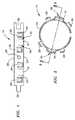
- FIG. 1is a laid out view of the preferred embodiment of the electrical conducting spring member of the present invention.
- FIG. 2is a plan view of the preferred embodiment of the spring member as viewed from the trailing end.
- FIG. 3is a sectional view of the spring member taken along line 3 - 3 of FIG. 2 .
- FIG. 4is a side view of the spring member of FIG. 1 .
- FIG. 5is a plan view of the preferred embodiment of the spring member as viewed from the leading end.
- FIG. 6is a side view of the preferred embodiment of the spring member with the leading end on the left of the figure and the trailing end on the right.
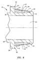
- FIG. 7is a side sectional view of the preferred embodiment of the fitting fully inserted into a hole in a junction box.
- FIG. 8is a side sectional view of the preferred embodiment of the fitting including the preferred embodiment of the spring member seated on the leading end of the connector.
- the present inventioncomprises a fitting that provides improved electrical continuity between the fitting itself, an inserted cable, and an electrically conducting electrical junction box.
- This inventionrelates to and incorporates herein by reference in its entirety pending U.S. application Ser. No. 10/034,156 filed Dec. 26, 2001 and titled “Threaded Snap In Connector”.
- a sectional view of the fitting with improved continuityis depicted by reference numeral 10 and includes a hollow electrical connector 12 , a cylindrical electrical conducting spring member 14 , and at least two integral outward-bent grounding tangs 16 supported at one end from the spring member 14 .
- the electrical connector 12has a leading end 18 which will be inserted into a junction box (not shown) and a trailing end 20 , a portion of which is cutaway in FIG. 8.
- a central bore 22extends through the connector 12 .
- FIG. 1illustrates a laid out view of the preferred embodiment of the spring member 14 of the present invention after it has been stamped out of a flat piece of metal.
- the spring member 14includes a trailing edge 24 and a leading edge 26 and one or more integral spring locking members 28 .
- FIG. 1depicts a preferred embodiment of the spring member 14 with four spring locking members 28 spaced at roughly even intervals across the spring member 14 .
- U-shaped slots 30preferably surround each of the spring locking members 28 .
- Slits 32 stamped along the trailing edge 24 of the spring member 14form the sides 34 of two integral outward-bent grounding tangs 16 .
- the spring memberincludes a first end 36 that is shaped into a tab that will fit within a slot in the second end 38 .
- the hole 40 depicted in the center of the spring member 14is used only for locking the spring member 14 into a mandrel (not shown) to bend it into its cylindrical shape and is not material to the invention.
- FIG. 2a plan view is shown of the preferred embodiment of the electrical conducting spring member 14 after it has been formed into the cylindrical shape required for use in the invention.
- FIG. 2shows the spring member 14 as viewed from the trailing edge 24 .
- both grounding tangs 16 and the four spring locking members 28are all bent outwards of the cylindrical ring portion.
- FIG. 3depicts a sectional view of the spring member 14 taken along line 3 — 3 of FIG. 2 .
- the grounding tangs 16are visible along the trailing edge 24 where they are bent outwards of the cylindrical periphery of the spring member 14 .
- the grounding tangs 16are integral with and supported at one end from the spring member 14 and therefore have a supported end 42 and an unsupported or trailing end 44 .
- the cylindrical-shaped spring member 14is preferably wider in diameter at its middle 46 than at the trailing edge 24 or leading edge 26 .
- the grounding tang 16is first bent outwards from its supported end 42 with a rising slope 48 to a crest 50 and then with a downward slope 52 to its trailing end 44 .
- FIG. 4a side view is shown of the preferred embodiment of the spring member 14 .
- the leading edge 26 of the spring member 14is on the right side of the figure with the trailing edge 24 on the left of the figure.
- the cylindrical spring member 14is typically wider in diameter in the middle 46 than at the leading 26 or trailing 24 edges.
- Two of the spring locking members 28 and one of the grounding tangs 16are visible in the side view of FIG. 4 .
- U-shaped slots 30are visible around each spring locking member 28 .
- the grounding tang 16includes a rising slope section 48 , a crest 50 , and a downward slope section 52 .
- FIG. 5is a plan view of the preferred embodiment of the spring member 14 as viewed from the leading edge 26 .
- Two grounding tangs 16are visible spaced roughly 180° apart on the outer periphery of the cylindrical spring member 14 .
- Four spring locking members 28are visible and spaced roughly 90° apart on the outer periphery of the cylindrical spring member 14 .
- a small gap 54exists as shown between the first 36 and second 38 end of the spring member 14 after the spring spring member 14 is formed into its cylindrical shape.
- FIG. 8a side sectional view is shown of the preferred embodiment of the fitting 10 with the preferred embodiment of the electrical conducting spring member 14 fitted on the leading end 18 of the hollow electrical connector 12 .
- the connector 12includes a flange 56 on its leading end 18 , a shoulder 58 on its trailing end, and a smooth intermediate portion 60 therebetween to provide a seat for the spring member 14 .
- the spring member 14When formed into its cylindrical shape, the spring member 14 is initially formed into a cylindrical shape with a diameter less than the outer diameter around the smooth intermediate portion 60 . When the spring member 14 is pushed over the leading end 18 of the connector 12 , it therefore snaps and holds tightly around the intermediate portion 60 of the leading end 18 of the connector 12 .
- a face 62is formed on the leading side of the shoulder 58 .
- the operation of the present inventionmay be explained by referring first to FIG. 8 .
- the electrical conducting spring member 14being constructed of spring steel or equivalent material and being of smaller diameter than the flange 56 at the leading end 18 of the hollow electrical connector 12 , is pushed over the leading end 18 of the connector 12 until it snaps onto the intermediate portion 60 .
- the electrical connector 12 with the spring member 14 snapped theretoform the fitting of the present invention.
- the spring member 14resides on the intermediate portion 60 of the connector 12 .
- the outer diameter of the grounding tangs 16extend beyond the outer diameter of the middle 46 portion of the spring member 14 and to a greater diameter than the diameter of a hole (not shown) in a junction box that it will be used in conjunction with.
- the spring member 14includes a leading edge 26 that fits against the flange 56 on the leading end 18 of the connector 12 and a trailing edge 24 that fits against the face 62 of the shoulder 58 toward the trailing end 20 of the connector 12 .
- the fitting 10may then be pushed, leading end 18 first, into a hole 64 in an electrically conductive electrical junction box, the walls 66 of which are shown in FIG. 7 .
- the surrounding walls 66first contact the rising slope 48 on the supported ends 42 of the grounding tangs 16 forcing the grounding tangs 16 to compress inward.
- the snap tight fitting 10 of the present inventioncan be designed for various typical trade sizes of access holes that may be encountered in junction boxes.
- a 1 ⁇ 2′′ trade size spring member 14is designed to fit a 0.875′′ diameter standard hole in a junction box.
- the spring member 14preferably measures 0.945′′ in diameter measured across the cylindrical spring member 14 from the crest 50 of one grounding tang 16 to the crest 50 of the grounding tang 16 180° across from it, such as would be measured across line 3 — 3 of FIG. 2 .
- the preferred diameter measured across the spring locking members 28located 180° apart, as shown in FIG. 2, is typically 1.025′′ for the 1 ⁇ 2′′ trade size spring member 14 .
- the width of the 1 ⁇ 2′′ trade size spring member 14is preferably 0.375′′.
- the wall thickness of a typical junction boxis typically 0.060′′ and the length of the downward slope 52 portion of the grounding tang 16 between the crest 50 and the trailing edge 24 is typically 0.090′′, therefore once the crest 50 has cleared the hole 64 the downward slope 52 portion will tend to pull the fitting 10 tight against the face 62 of the connector 12 .
Landscapes
- Engineering & Computer Science (AREA)
- Architecture (AREA)
- Civil Engineering (AREA)
- Structural Engineering (AREA)
- Connection Or Junction Boxes (AREA)
- Details Of Connecting Devices For Male And Female Coupling (AREA)
Abstract
Description
This invention relates to fittings for electrically conducting electrical junction boxes and specifically to an improved fitting that provides improved electrical continuity between the fitting, the cable, and the junction box.
Historically, the most common form of attaching cable and electrical metal tubing (EMT) to electrical junction boxes was by means of an interior-threaded lock nut, which is screwed onto the exterior-threaded electrical fitting that extends into the junction box.
Recently, snap fitting connectors have become popular as a means of connecting cables to electrical junction boxes. One such type of snap fitting is disclosed in U.S. Pat. No. 5,373,106 (hereinafter the '106 patent) issued Dec. 13, 1994, and entitled “Snap In Cable Connector”. This patent disclosed a quick connect fitting for an electrical junction box including a spring steel spring member that improved the ease of use and reduced the time involved in securing electrical connectors to electrical junction boxes. This application also disclosed the use of outward-bent tensioner tangs to provide electrical continuity or ground between the electrical connector, the junction box, and the source leading to the box as an integral part of the design of the connector.
Although the '106 patent provided an improved quick connect fitting, the present invention further improves the functionality of the quick connect fitting by providing a tensioner or grounding tang of a novel design that holds the quick connect fitting more tightly to the junction box and therefore vastly improves the electrical continuity and lowers the millivolt droop between the fitting, the cable, and the junction box. These and other advantages will become apparent by reading the attached specification and claims in conjunction with reference to the attached drawings.
The present invention comprises a fitting that exhibits improved electrical continuity between the fitting, the cable, and the junction box. The fitting features a hollow electrical connector having an electrical conducting spring member surrounding its leading end with the member including one or more grounding tangs and spring locking members cantilevered from its outer circumference. When the fitting is pushed into a hole in a junction box, the locking members are first compressed by the surrounding wall of the junction box and after clearing the wall snap outwards to lock the fitting into the box. The grounding tangs, located near the trailing end of the spring member, extend at a rising slope from their supported end to a crest and then at a downward slope back towards the fitting such that when the fitting is pressed into a hole in a junction box, the grounding tangs are compressed by the surrounding wall of the junction box toward the fitting until the crest clears the surrounding wall whereupon the springiness of the grounding tangs and the downward slope cause the fitting to be drawn tightly against the junction box wall and therefore vastly improve electrical continuity between the fitting, cable, and box.
FIG. 1 is a laid out view of the preferred embodiment of the electrical conducting spring member of the present invention.
FIG. 2 is a plan view of the preferred embodiment of the spring member as viewed from the trailing end.
FIG. 3 is a sectional view of the spring member taken along line3-3 of FIG.2.
FIG. 4 is a side view of the spring member of FIG.1.
FIG. 5 is a plan view of the preferred embodiment of the spring member as viewed from the leading end.
FIG. 6 is a side view of the preferred embodiment of the spring member with the leading end on the left of the figure and the trailing end on the right.
FIG. 7 is a side sectional view of the preferred embodiment of the fitting fully inserted into a hole in a junction box.
FIG. 8 is a side sectional view of the preferred embodiment of the fitting including the preferred embodiment of the spring member seated on the leading end of the connector.
| Index to Reference Numerals in |
| 10 | fitting |
| 12 | hollow |
| 14 | electrical conducting |
| 16 | |
| 18 | leading end (of connector) |
| 20 | trailing end (of connector) |
| 22 | |
| 24 | trailing edge (of spring member) |
| 26 | leading edge (of spring member) |
| 28 | |
| 30 | U-shaped |
| 32 | |
| 34 | side (of grounding tang) |
| 36 | first end (of spring member) |
| 38 | second end (of spring member) |
| 40 | hole (for mandrel) |
| 42 | supported end (of grounding tang) |
| 44 | trailing end (of grounding tang) |
| 46 | middle (of spring member) |
| 48 | rising slope (of grounding tang) |
| 50 | crest (of grounding tang) |
| 52 | downward slope (of grounding tang) |
| 54 | |
| 56 | |
| 58 | |
| 60 | smooth |
| 62 | |
| 64 | hole (in junction box) |
| 66 | |
| 68 | inner edge (of surrounding wall) |
The present invention comprises a fitting that provides improved electrical continuity between the fitting itself, an inserted cable, and an electrically conducting electrical junction box. This invention relates to and incorporates herein by reference in its entirety pending U.S. application Ser. No. 10/034,156 filed Dec. 26, 2001 and titled “Threaded Snap In Connector”.
Referring to FIG. 8, a sectional view of the fitting with improved continuity is depicted byreference numeral 10 and includes a hollowelectrical connector 12, a cylindrical electrical conductingspring member 14, and at least two integral outward-bent grounding tangs 16 supported at one end from thespring member 14. Theelectrical connector 12 has a leadingend 18 which will be inserted into a junction box (not shown) and atrailing end 20, a portion of which is cutaway in FIG. 8. Acentral bore 22 extends through theconnector 12.
FIG. 1 illustrates a laid out view of the preferred embodiment of thespring member 14 of the present invention after it has been stamped out of a flat piece of metal. Thespring member 14 includes atrailing edge 24 and a leadingedge 26 and one or more integralspring locking members 28. FIG. 1 depicts a preferred embodiment of thespring member 14 with fourspring locking members 28 spaced at roughly even intervals across thespring member 14. U-shapedslots 30 preferably surround each of thespring locking members 28. Slits32 stamped along thetrailing edge 24 of thespring member 14 form thesides 34 of two integral outward-bent grounding tangs 16. The spring member includes afirst end 36 that is shaped into a tab that will fit within a slot in thesecond end 38. Thehole 40 depicted in the center of thespring member 14 is used only for locking thespring member 14 into a mandrel (not shown) to bend it into its cylindrical shape and is not material to the invention.
Referring to FIG. 2, a plan view is shown of the preferred embodiment of the electrical conductingspring member 14 after it has been formed into the cylindrical shape required for use in the invention. FIG. 2 shows thespring member 14 as viewed from thetrailing edge 24. As shown in the figure, both groundingtangs 16 and the fourspring locking members 28 are all bent outwards of the cylindrical ring portion.
FIG. 3 depicts a sectional view of thespring member 14 taken alongline 3—3 of FIG.2. In this view, thegrounding tangs 16 are visible along thetrailing edge 24 where they are bent outwards of the cylindrical periphery of thespring member 14. Thegrounding tangs 16 are integral with and supported at one end from thespring member 14 and therefore have a supportedend 42 and an unsupported ortrailing end 44. The cylindrical-shaped spring member 14 is preferably wider in diameter at itsmiddle 46 than at thetrailing edge 24 or leadingedge 26. Following the outer periphery of thespring member 14 from the leadingedge 26 to thetrailing edge 24 shown in FIG. 3, thegrounding tang 16 is first bent outwards from its supportedend 42 with a risingslope 48 to acrest 50 and then with adownward slope 52 to itstrailing end 44.
Referring to FIG. 4, a side view is shown of the preferred embodiment of thespring member 14. The leadingedge 26 of thespring member 14 is on the right side of the figure with thetrailing edge 24 on the left of the figure. As depicted, thecylindrical spring member 14 is typically wider in diameter in themiddle 46 than at the leading26 or trailing24 edges. Two of thespring locking members 28 and one of thegrounding tangs 16 are visible in the side view of FIG.4. U-shapedslots 30 are visible around eachspring locking member 28. Thegrounding tang 16 includes a risingslope section 48, acrest 50, and adownward slope section 52.
FIG. 5 is a plan view of the preferred embodiment of thespring member 14 as viewed from the leadingedge 26. Twogrounding tangs 16 are visible spaced roughly 180° apart on the outer periphery of thecylindrical spring member 14. Fourspring locking members 28 are visible and spaced roughly 90° apart on the outer periphery of thecylindrical spring member 14. Asmall gap 54 exists as shown between the first36 and second38 end of thespring member 14 after thespring spring member 14 is formed into its cylindrical shape.
Referring to FIG. 8 again, a side sectional view is shown of the preferred embodiment of thefitting 10 with the preferred embodiment of the electrical conductingspring member 14 fitted on the leadingend 18 of the hollowelectrical connector 12. Theconnector 12 includes aflange 56 on its leadingend 18, ashoulder 58 on its trailing end, and a smoothintermediate portion 60 therebetween to provide a seat for thespring member 14. When formed into its cylindrical shape, thespring member 14 is initially formed into a cylindrical shape with a diameter less than the outer diameter around the smoothintermediate portion 60. When thespring member 14 is pushed over the leadingend 18 of theconnector 12, it therefore snaps and holds tightly around theintermediate portion 60 of the leadingend 18 of theconnector 12. Aface 62 is formed on the leading side of theshoulder 58.
The operation of the present invention may be explained by referring first to FIG.8. The electrical conductingspring member 14, being constructed of spring steel or equivalent material and being of smaller diameter than theflange 56 at the leadingend 18 of the hollowelectrical connector 12, is pushed over the leadingend 18 of theconnector 12 until it snaps onto theintermediate portion 60. Theelectrical connector 12 with thespring member 14 snapped thereto form the fitting of the present invention. As shown in FIG. 8, thespring member 14 resides on theintermediate portion 60 of theconnector 12. The outer diameter of the grounding tangs16 extend beyond the outer diameter of the middle46 portion of thespring member 14 and to a greater diameter than the diameter of a hole (not shown) in a junction box that it will be used in conjunction with. Thespring member 14 includes aleading edge 26 that fits against theflange 56 on the leadingend 18 of theconnector 12 and a trailingedge 24 that fits against theface 62 of theshoulder 58 toward the trailingend 20 of theconnector 12. Referring to FIG. 7, the fitting10 may then be pushed, leadingend 18 first, into ahole 64 in an electrically conductive electrical junction box, thewalls 66 of which are shown in FIG.7. As theleading end 18 enters thehole 64, the surroundingwalls 66 first contact the risingslope 48 on the supported ends42 of the grounding tangs16 forcing the grounding tangs16 to compress inward. Continued advancement of the fitting10 into thehole 64 of the junction box causes thecrest 50 of the grounding tangs16 to slip within the surroundingwalls 66 and therefore creates the greatest compression of the grounding tangs16. Further advancement of the fitting10 then causes thedownward slope 52 of the grounding tangs16 to contact theinner edge 68 of the surrounding wall whereupon thedownward slope 52 and the tendency of the grounding tangs16 to spring outwards to their unbiased or relaxed position causes theface 62 of the fitting10 to be drawn tightly against thewall 66 of the junction box. Thedownward slope 52 of the grounding tangs16 and the outward force exerted by the grounding tangs16 trying to return to their unbiased or relaxed state hold the fitting10 tightly against theface 62 of theshoulder 58 thereby creating good electrical continuity and low millivolt drop between the fitting10 and the junction box (wall portion shown).
The snaptight fitting 10 of the present invention can be designed for various typical trade sizes of access holes that may be encountered in junction boxes. For example, a ½″ tradesize spring member 14 is designed to fit a 0.875″ diameter standard hole in a junction box. For the 0.875″ diameter hole, thespring member 14 preferably measures 0.945″ in diameter measured across thecylindrical spring member 14 from thecrest 50 of one groundingtang 16 to thecrest 50 of the groundingtang 16 180° across from it, such as would be measured acrossline 3—3 of FIG.2. The preferred diameter measured across thespring locking members 28, located 180° apart, as shown in FIG. 2, is typically 1.025″ for the ½″ tradesize spring member 14. The width of the ½″ tradesize spring member 14, as measured from the trailingedge 24 to the leadingedge 26 shown in FIG. 1, is preferably 0.375″. Referring to FIG. 7, the wall thickness of a typical junction box is typically 0.060″ and the length of thedownward slope 52 portion of the groundingtang 16 between thecrest 50 and the trailingedge 24 is typically 0.090″, therefore once thecrest 50 has cleared thehole 64 thedownward slope 52 portion will tend to pull the fitting10 tight against theface 62 of theconnector 12.
Although the description above contains many specific descriptions, materials, and dimensions, these should not be construed as limiting the scope of the invention but as merely providing illustrations of some of the presently preferred embodiments of this invention. Thus the scope of the invention should be determined by the appended claims and their legal equivalents, rather than by the examples given.
Claims (5)
1. A fitting for an electrically conducting electrical junction box comprising:
a hollow electrically conductive connector through which an electrical conductor is inserted with said connector having a leading end thereof for insertion in a hole in an electrical junction box and a face for limiting the depth of insertion of said connector in said hole;
an electrically conductive spring member surrounding said leading end of said electrical connector which has a leading portion and trailing portion;
a spring locking member integral with and cantilevered at one end from said spring member, said spring locking member springs inward to permit said spring member and said locking member to be inserted in said hole in said junction box and springs outward to lock said electrical connector from being withdrawn from said hole; and
a grounding tang integral with and supported at one end from said spring member and free at its trailing end with said grounding tang having a rising slope at said supported end, a downward slope at said trailing end and a crest separating said rising slope and said downward slope allowing said grounding tang to spring inward as said leading portion is inserted in said hole in said junction box and further allowing said grounding tang to spring outward after said crest clears said hole of said junction box thereby enabling said grounding tang to draw said face of said electrical connector against said junction box and provide electrical continuity between said junction box and said electrical connector.
2. The fitting ofclaim 1 wherein said spring member is less than a complete circle and includes a relaxed diameter, said hole includes a diameter, and said relaxed diameter of said spring member is less than said diameter of said hole thereby enabling said spring locking member and said crest of said grounding tang to extend beyond said diameter of said hole.
3. The fitting ofclaim 1 wherein said spring member is a split ring with the two ends of the ring shaped to overlap one another.
4. The fitting ofclaim 1 wherein said connector includes a flange and shoulder with a smooth intermediate portion therebetween with said spring member carried on said intermediate portion and held in position by said flange and said shoulder.
5. A method for quickly connecting fittings to electrical junction boxes comprising:
providing an electrically conductive electrical junction box with a hole, said hole having a diameter;
providing an electrically conductive electrical connector having a leading end for insertion in said hole and a face limiting the distance said connector is inserted in said hole;
providing a circular electrically conductive spring member surrounding said leading end of said electrical connector with said spring member having a leading portion and a trailing portion;
providing at least one spring locking member on said spring member that has a relaxed outer dimension greater than said diameter of said hole;
providing at least one grounding tang integral with and supported at one end from said spring member and free at its opposite end, said grounding tang having a rising slope at said supported end, a downward slope at said trailing end and a crest separating said rising slope and said downward slope; and
inserting said leading end of said electrical connector with said surrounding spring member into said hole until said crest of said grounding tang clears said hole and said grounding tang draws said face of said electrical connector against said junction box thereby providing electrical continuity between said junction box and said electrical connector.
Priority Applications (5)
| Application Number | Priority Date | Filing Date | Title |
|---|---|---|---|
| US10/053,076US6709280B1 (en) | 2002-01-17 | 2002-01-17 | Fitting with improved continuity |
| US10/256,641US6780029B1 (en) | 2002-01-17 | 2002-09-27 | High continuity electrical fitting |
| US10/286,228US6670553B1 (en) | 1998-01-15 | 2002-11-01 | Snap engagement electrical fitting for EMT |
| US10/348,111US6682355B1 (en) | 1998-01-15 | 2003-01-21 | Electrical fitting for easy snap engagement of cables |
| US10/923,468US6957968B1 (en) | 2002-01-17 | 2004-08-20 | Snap engagement electrical fitting with flangeless body |
Applications Claiming Priority (1)
| Application Number | Priority Date | Filing Date | Title |
|---|---|---|---|
| US10/053,076US6709280B1 (en) | 2002-01-17 | 2002-01-17 | Fitting with improved continuity |
Related Parent Applications (1)
| Application Number | Title | Priority Date | Filing Date |
|---|---|---|---|
| US09/792,184Continuation-In-PartUS6604400B1 (en) | 1998-01-15 | 2001-02-23 | Electrical connector |
Related Child Applications (1)
| Application Number | Title | Priority Date | Filing Date |
|---|---|---|---|
| US10/256,641Continuation-In-PartUS6780029B1 (en) | 1998-01-15 | 2002-09-27 | High continuity electrical fitting |
Publications (1)
| Publication Number | Publication Date |
|---|---|
| US6709280B1true US6709280B1 (en) | 2004-03-23 |
Family
ID=31975618
Family Applications (2)
| Application Number | Title | Priority Date | Filing Date |
|---|---|---|---|
| US10/053,076Expired - LifetimeUS6709280B1 (en) | 1998-01-15 | 2002-01-17 | Fitting with improved continuity |
| US10/256,641Expired - LifetimeUS6780029B1 (en) | 1998-01-15 | 2002-09-27 | High continuity electrical fitting |
Family Applications After (1)
| Application Number | Title | Priority Date | Filing Date |
|---|---|---|---|
| US10/256,641Expired - LifetimeUS6780029B1 (en) | 1998-01-15 | 2002-09-27 | High continuity electrical fitting |
Country Status (1)
| Country | Link |
|---|---|
| US (2) | US6709280B1 (en) |
Cited By (55)
| Publication number | Priority date | Publication date | Assignee | Title |
|---|---|---|---|---|
| US20040113368A1 (en)* | 2002-10-16 | 2004-06-17 | Karl Smirra | Sealing device and method for assembling the sealing device |
| US20070190864A1 (en)* | 2005-01-04 | 2007-08-16 | Lloyd Brian K | Retaining and grounding clip for adapter module |
| US7476817B1 (en) | 2006-11-29 | 2009-01-13 | Sami Shemtov | Connector for affixing cables within junction boxes |
| US20090218131A1 (en)* | 2008-02-29 | 2009-09-03 | Sigma Electric Manufacturing Corporation | Conduit connector |
| US20100084854A1 (en)* | 2008-10-08 | 2010-04-08 | Sigma Electric Manufacturing Corporation | Conduit connector and methods for making and using the same |
| US20100279530A1 (en)* | 2009-05-04 | 2010-11-04 | Auray Delbert L | Snap-in Electrical Connector with Locking Cam and Method of Use |
| US20110250776A1 (en)* | 2010-02-24 | 2011-10-13 | Kiely Kenneth M | Slotted Retainer Ring for Snap-in Electrical Connector |
| US20120270441A1 (en)* | 2005-01-25 | 2012-10-25 | Corning Gilbert Inc. | Electrical connector with grounding member |
| US8350163B2 (en) | 2004-09-13 | 2013-01-08 | Bridgeport, Fittings, Inc. | Electrical connector having snap in frustro-conical retaining ring with improved conductivity |
| CN103795012A (en)* | 2014-01-27 | 2014-05-14 | 中铁建设集团设备安装有限公司 | Hidden support and bridge device and installation method thereof |
| US8791377B2 (en) | 2010-07-27 | 2014-07-29 | Keemaya LLC | Spring lock electrical fitting |
| US8801448B2 (en) | 2009-05-22 | 2014-08-12 | Ppc Broadband, Inc. | Coaxial cable connector having electrical continuity structure |
| US8803008B2 (en) | 2011-03-03 | 2014-08-12 | Sigma Electric Manufacturing Corporation | Conduit connector and methods for making and using the same |
| US8858251B2 (en) | 2010-11-11 | 2014-10-14 | Ppc Broadband, Inc. | Connector having a coupler-body continuity member |
| US8857039B2 (en) | 2010-02-19 | 2014-10-14 | Sigma Electric Manufacturing Corporation | Electrical box conduit connectors and methods for making and using the same |
| US8888526B2 (en) | 2010-08-10 | 2014-11-18 | Corning Gilbert, Inc. | Coaxial cable connector with radio frequency interference and grounding shield |
| CN104373693A (en)* | 2013-08-13 | 2015-02-25 | 诺马德国有限责任公司 | Wall feedthrough element for a fluid line and wall feedthrough |
| US9017101B2 (en) | 2011-03-30 | 2015-04-28 | Ppc Broadband, Inc. | Continuity maintaining biasing member |
| US9048599B2 (en) | 2013-10-28 | 2015-06-02 | Corning Gilbert Inc. | Coaxial cable connector having a gripping member with a notch and disposed inside a shell |
| US9071019B2 (en) | 2010-10-27 | 2015-06-30 | Corning Gilbert, Inc. | Push-on cable connector with a coupler and retention and release mechanism |
| US9136654B2 (en) | 2012-01-05 | 2015-09-15 | Corning Gilbert, Inc. | Quick mount connector for a coaxial cable |
| US9147963B2 (en) | 2012-11-29 | 2015-09-29 | Corning Gilbert Inc. | Hardline coaxial connector with a locking ferrule |
| US9153911B2 (en) | 2013-02-19 | 2015-10-06 | Corning Gilbert Inc. | Coaxial cable continuity connector |
| US9166348B2 (en) | 2010-04-13 | 2015-10-20 | Corning Gilbert Inc. | Coaxial connector with inhibited ingress and improved grounding |
| US9172154B2 (en) | 2013-03-15 | 2015-10-27 | Corning Gilbert Inc. | Coaxial cable connector with integral RFI protection |
| US9190744B2 (en) | 2011-09-14 | 2015-11-17 | Corning Optical Communications Rf Llc | Coaxial cable connector with radio frequency interference and grounding shield |
| US9203167B2 (en) | 2011-05-26 | 2015-12-01 | Ppc Broadband, Inc. | Coaxial cable connector with conductive seal |
| US9231388B2 (en) | 2011-09-01 | 2016-01-05 | Sigma Electric Manufactruing Corporation | Conduit connector and method for making and using the same |
| US9287659B2 (en) | 2012-10-16 | 2016-03-15 | Corning Optical Communications Rf Llc | Coaxial cable connector with integral RFI protection |
| US9407016B2 (en) | 2012-02-22 | 2016-08-02 | Corning Optical Communications Rf Llc | Coaxial cable connector with integral continuity contacting portion |
| US20160348810A1 (en)* | 2015-05-27 | 2016-12-01 | Brian Michael Kipp | Gripping device and method of using |
| US9525220B1 (en) | 2015-11-25 | 2016-12-20 | Corning Optical Communications LLC | Coaxial cable connector |
| US9548572B2 (en) | 2014-11-03 | 2017-01-17 | Corning Optical Communications LLC | Coaxial cable connector having a coupler and a post with a contacting portion and a shoulder |
| US9548557B2 (en) | 2013-06-26 | 2017-01-17 | Corning Optical Communications LLC | Connector assemblies and methods of manufacture |
| US9570845B2 (en) | 2009-05-22 | 2017-02-14 | Ppc Broadband, Inc. | Connector having a continuity member operable in a radial direction |
| US9590287B2 (en) | 2015-02-20 | 2017-03-07 | Corning Optical Communications Rf Llc | Surge protected coaxial termination |
| US9595776B2 (en) | 2011-03-30 | 2017-03-14 | Ppc Broadband, Inc. | Connector producing a biasing force |
| US9711917B2 (en) | 2011-05-26 | 2017-07-18 | Ppc Broadband, Inc. | Band spring continuity member for coaxial cable connector |
| US9762008B2 (en) | 2013-05-20 | 2017-09-12 | Corning Optical Communications Rf Llc | Coaxial cable connector with integral RFI protection |
| US9859631B2 (en) | 2011-09-15 | 2018-01-02 | Corning Optical Communications Rf Llc | Coaxial cable connector with integral radio frequency interference and grounding shield |
| US9929551B2 (en) | 2015-11-02 | 2018-03-27 | Hubbell Incorporated | Electrical box cable connector |
| US10033122B2 (en) | 2015-02-20 | 2018-07-24 | Corning Optical Communications Rf Llc | Cable or conduit connector with jacket retention feature |
| US10167891B1 (en)* | 2018-03-08 | 2019-01-01 | International Business Machines Corporation | Self-reporting, grounded nut-clip |
| US10211547B2 (en) | 2015-09-03 | 2019-02-19 | Corning Optical Communications Rf Llc | Coaxial cable connector |
| US10263404B2 (en) | 2015-12-07 | 2019-04-16 | Hubbell Incorporated | Electrical box cable clamp |
| US10269473B1 (en)* | 2014-03-07 | 2019-04-23 | Arlington Industries, Inc. | Electrical insider fitting for internal connection to an electrical box |
| US10290958B2 (en) | 2013-04-29 | 2019-05-14 | Corning Optical Communications Rf Llc | Coaxial cable connector with integral RFI protection and biasing ring |
| US10644491B2 (en) | 2017-10-13 | 2020-05-05 | Hubbell Incorporated | Electrical box cable connector |
| US10700472B2 (en) | 2017-10-06 | 2020-06-30 | Hubbell Incorporated | Cable connector |
| US10967712B2 (en)* | 2016-02-04 | 2021-04-06 | Kabushiki Kaisha Toyota Jidoshokki | Register panel mounting structure |
| JP2021515364A (en)* | 2018-02-28 | 2021-06-17 | ローベルト ボツシユ ゲゼルシヤフト ミツト ベシユレンクテル ハフツングRobert Bosch Gmbh | How to manufacture connector systems and connector systems |
| US11271379B1 (en)* | 2015-02-07 | 2022-03-08 | Arlington Industries, Inc. | Snap fit electrical fitting for ninety degree connection of electrical cables to an electrical box |
| US11387639B2 (en) | 2018-07-11 | 2022-07-12 | Hubbell Incorporated | Electrical box cable connector |
| US12034264B2 (en) | 2021-03-31 | 2024-07-09 | Corning Optical Communications Rf Llc | Coaxial cable connector assemblies with outer conductor engagement features and methods for using the same |
| KR20250018354A (en)* | 2023-07-27 | 2025-02-05 | 주식회사유비씨에스 | Socket for electric device |
Families Citing this family (22)
| Publication number | Priority date | Publication date | Assignee | Title |
|---|---|---|---|---|
| US6860758B1 (en)* | 2002-10-30 | 2005-03-01 | Bridgeport Fittings, Inc. | Snap fitting electrical connector |
| US7494157B1 (en) | 2004-04-28 | 2009-02-24 | Bridgeport Fittings, Inc. | Electrical connector with snap fit retaining ring with improved holding and grounding tangs |
| US7723623B2 (en)* | 2004-09-13 | 2010-05-25 | Bridgeport Fittings, Inc. | Electrical duplex connector having an integrally formed connector body with a frustro-conical retaining ring and unidirectional cable retainers |
| US7488905B2 (en) | 2004-09-13 | 2009-02-10 | Bridgeport Fittings, Inc. | Electrical connector with outer retainer ring and internal unidirectional conductor retainer |
| US7952034B2 (en)* | 2004-09-13 | 2011-05-31 | Bridgeport Fittings, Inc. | Strap type electrical connector with frustro-conical retaining ring and improved clamping strap for either nonmetallic cables or armor or metal clad cables |
| US8119933B2 (en)* | 2004-09-13 | 2012-02-21 | Bridgeport Fittings, Inc. | Duplex electrical connector with frustro-conical retaining ring and crimped inlet end |
| US7064272B2 (en)* | 2004-09-13 | 2006-06-20 | Bridgeport Fittings, Inc. | Snap in electrical connector assembly with unidirectional wire conductor retainer ring |
| US7154042B2 (en)* | 2004-09-13 | 2006-12-26 | Bridgeport Fittings, Inc. | Electrical connector with snap fit retainer ring constructed to enhance the connection of the connector to an electrical box |
| US7358448B2 (en)* | 2004-09-13 | 2008-04-15 | Bridgeport Fittings, Inc. | Electrical connector assembly with frusto-conical snap fit retaining ring for enhancing electrical grounding of the connector assembly to an electrical box and installation tool therefor |
| US8143535B2 (en)* | 2004-09-13 | 2012-03-27 | Bridgeport Fittings, Inc. | Electrical connector assembly with enhanced grounding |
| US7057107B2 (en)* | 2004-09-13 | 2006-06-06 | Bridgeport Fittings, Inc. | Snap fit electrical connector assembly with conical outer snap fit retainer and externally mounted internal wire retainer |
| US7075007B2 (en)* | 2004-09-13 | 2006-07-11 | Bridgeport Fittings, Inc. | Snap fit electrical connector assembly with conical outer snap fit retainer and one or more internal snap fit wire retainers |
| US7214890B2 (en) | 2004-09-13 | 2007-05-08 | Bridgeport Fittings, Inc. | Electrical connector having an outlet end angularly disposed relative an inlet end with outer retainer ring about the outlet end and internal unidirectional conductor retainer in the inlet end |
| US7205489B2 (en)* | 2004-09-13 | 2007-04-17 | Bridgeport Fittings, Inc. | Snap fit electrical connector assembly with operating tool for facilitating the connection of a connector assembly to an electrical box |
| US7151223B2 (en)* | 2004-09-13 | 2006-12-19 | Bridgeport Fittings, Inc. | Snap fit electrical connector assembly with outer frustro conical retainer ring and internal unidirectional snap fit wire conductor retainer |
| JP2006269370A (en)* | 2005-03-25 | 2006-10-05 | Orion Denki Kk | Electronic apparatus equipped with jack |
| CN201202720Y (en)* | 2008-05-12 | 2009-03-04 | 钛积创新科技股份有限公司 | Stud positioning device |
| FR2947889A1 (en)* | 2009-07-08 | 2011-01-14 | Legris Sas | INSERTION TIP FOR CONNECTION OR ANALOG WITH LOW EMERGENCY FEED |
| US8076573B1 (en) | 2009-12-30 | 2011-12-13 | Arlington Industries, Inc. | Electrical box hanger |
| US9490619B2 (en)* | 2012-10-25 | 2016-11-08 | Bridgeport Fittings, Inc. | Push-on liquidtight conduit fitting |
| US9662725B2 (en) | 2013-03-15 | 2017-05-30 | Milwaukee Electric Tool Corporation | Saw blade and system and method for manufacturing a saw blade |
| US10700479B1 (en)* | 2019-04-30 | 2020-06-30 | Paul Wesley Smith | Cable adapter panel retention clip |
Citations (17)
| Publication number | Priority date | Publication date | Assignee | Title |
|---|---|---|---|---|
| US1483218A (en)* | 1919-09-27 | 1924-02-12 | Fahnestock Electric Company | Insulating bushing |
| US3814467A (en)* | 1972-04-17 | 1974-06-04 | Trw Inc | Connector for flexible conduit |
| US4032178A (en)* | 1975-09-04 | 1977-06-28 | Neuroth Robert J | Electric conduit connector |
| US4198537A (en)* | 1978-08-21 | 1980-04-15 | Thomas & Betts Corporation | Connector |
| US4361302A (en)* | 1980-09-19 | 1982-11-30 | Square D Company | Cable clamp for electrical outlet box |
| US4549755A (en)* | 1983-06-16 | 1985-10-29 | Efcor, Inc. | Armored cable connector |
| US4657212A (en)* | 1985-06-13 | 1987-04-14 | Acco Babcock Inc. | Automatic conduit anchorage device |
| US4773280A (en)* | 1987-04-01 | 1988-09-27 | Acco Babcock Inc. | Spring clip cable support assemblies |
| US4880387A (en)* | 1988-10-03 | 1989-11-14 | Ibc Corporation | Connector for flexible electrical conduit |
| US5373106A (en)* | 1991-12-04 | 1994-12-13 | Arlington Industries, Inc. | Quick-connect fitting for electrical junction box |
| US5496195A (en)* | 1995-03-13 | 1996-03-05 | The Whitaker Corporation | High performance shielded connector |
| US5934940A (en)* | 1997-07-23 | 1999-08-10 | Molex Incorporated | Shielded electrical connector |
| US5971811A (en)* | 1997-05-15 | 1999-10-26 | Yazaki Corporation | Shielded connector adapted to be directly attached to an apparatus |
| US5975957A (en)* | 1997-04-11 | 1999-11-02 | Molex Incorporated | I/O connector with resilient connecting means |
| US6050854A (en)* | 1997-09-17 | 2000-04-18 | Hon Hai Precision Ind. Co., Ltd. | Audio connector |
| US6099350A (en)* | 1999-09-10 | 2000-08-08 | Osram Sylvania Inc. | Connector and connector assembly |
| US6210217B1 (en)* | 1998-11-02 | 2001-04-03 | Hon Hai Precision Ind. Co., Ltd. | Electrical connector system having a connector mounted on a conductive panel |
Family Cites Families (8)
| Publication number | Priority date | Publication date | Assignee | Title |
|---|---|---|---|---|
| US4012578A (en)* | 1975-07-02 | 1977-03-15 | Eaton Corporation | One piece connector for flexible conduit |
| US4156103A (en)* | 1977-10-27 | 1979-05-22 | Amp Incorporated | Semi-rigid conduit connector |
| US4990721A (en)* | 1990-01-12 | 1991-02-05 | Corecon Corporation | Armored cable connector |
| US5422437A (en) | 1993-04-16 | 1995-06-06 | Hubbell Incorporated | Electrical connector assembly |
| US6043432A (en) | 1998-01-15 | 2000-03-28 | Arlington Industries, Inc. | Snap in cable connector |
| US6100470A (en) | 1999-02-26 | 2000-08-08 | Arlington Industries, Inc. | Separatable snap in connectors for pre-connectorized cable |
| US6538201B1 (en)* | 2001-12-26 | 2003-03-25 | Arlington Industries, Inc | Threaded snap in connector |
| US6642451B1 (en)* | 2001-10-22 | 2003-11-04 | Arlington Industries, Inc. | Electrical connector |
- 2002
- 2002-01-17USUS10/053,076patent/US6709280B1/ennot_activeExpired - Lifetime
- 2002-09-27USUS10/256,641patent/US6780029B1/ennot_activeExpired - Lifetime
Patent Citations (17)
| Publication number | Priority date | Publication date | Assignee | Title |
|---|---|---|---|---|
| US1483218A (en)* | 1919-09-27 | 1924-02-12 | Fahnestock Electric Company | Insulating bushing |
| US3814467A (en)* | 1972-04-17 | 1974-06-04 | Trw Inc | Connector for flexible conduit |
| US4032178A (en)* | 1975-09-04 | 1977-06-28 | Neuroth Robert J | Electric conduit connector |
| US4198537A (en)* | 1978-08-21 | 1980-04-15 | Thomas & Betts Corporation | Connector |
| US4361302A (en)* | 1980-09-19 | 1982-11-30 | Square D Company | Cable clamp for electrical outlet box |
| US4549755A (en)* | 1983-06-16 | 1985-10-29 | Efcor, Inc. | Armored cable connector |
| US4657212A (en)* | 1985-06-13 | 1987-04-14 | Acco Babcock Inc. | Automatic conduit anchorage device |
| US4773280A (en)* | 1987-04-01 | 1988-09-27 | Acco Babcock Inc. | Spring clip cable support assemblies |
| US4880387A (en)* | 1988-10-03 | 1989-11-14 | Ibc Corporation | Connector for flexible electrical conduit |
| US5373106A (en)* | 1991-12-04 | 1994-12-13 | Arlington Industries, Inc. | Quick-connect fitting for electrical junction box |
| US5496195A (en)* | 1995-03-13 | 1996-03-05 | The Whitaker Corporation | High performance shielded connector |
| US5975957A (en)* | 1997-04-11 | 1999-11-02 | Molex Incorporated | I/O connector with resilient connecting means |
| US5971811A (en)* | 1997-05-15 | 1999-10-26 | Yazaki Corporation | Shielded connector adapted to be directly attached to an apparatus |
| US5934940A (en)* | 1997-07-23 | 1999-08-10 | Molex Incorporated | Shielded electrical connector |
| US6050854A (en)* | 1997-09-17 | 2000-04-18 | Hon Hai Precision Ind. Co., Ltd. | Audio connector |
| US6210217B1 (en)* | 1998-11-02 | 2001-04-03 | Hon Hai Precision Ind. Co., Ltd. | Electrical connector system having a connector mounted on a conductive panel |
| US6099350A (en)* | 1999-09-10 | 2000-08-08 | Osram Sylvania Inc. | Connector and connector assembly |
Cited By (99)
| Publication number | Priority date | Publication date | Assignee | Title |
|---|---|---|---|---|
| US7401792B2 (en)* | 2002-10-16 | 2008-07-22 | Siemens Aktiengesellschaft | Sealing device and method for assembling the sealing device |
| US20040113368A1 (en)* | 2002-10-16 | 2004-06-17 | Karl Smirra | Sealing device and method for assembling the sealing device |
| US8350163B2 (en) | 2004-09-13 | 2013-01-08 | Bridgeport, Fittings, Inc. | Electrical connector having snap in frustro-conical retaining ring with improved conductivity |
| US20070190864A1 (en)* | 2005-01-04 | 2007-08-16 | Lloyd Brian K | Retaining and grounding clip for adapter module |
| US7438564B2 (en)* | 2005-01-04 | 2008-10-21 | Molex Incorporated | Retaining and grounding clip for adapter module |
| US20120270441A1 (en)* | 2005-01-25 | 2012-10-25 | Corning Gilbert Inc. | Electrical connector with grounding member |
| US8690603B2 (en)* | 2005-01-25 | 2014-04-08 | Corning Gilbert Inc. | Electrical connector with grounding member |
| US10756455B2 (en) | 2005-01-25 | 2020-08-25 | Corning Optical Communications Rf Llc | Electrical connector with grounding member |
| US7476817B1 (en) | 2006-11-29 | 2009-01-13 | Sami Shemtov | Connector for affixing cables within junction boxes |
| US8129634B2 (en) | 2008-02-29 | 2012-03-06 | Sigma Electric Manufacturing Corporation | Conduit connector |
| US20090218131A1 (en)* | 2008-02-29 | 2009-09-03 | Sigma Electric Manufacturing Corporation | Conduit connector |
| US8901441B2 (en) | 2008-10-08 | 2014-12-02 | Sigma Electric Manufacturing Corporation | Conduit connector and methods for making and using the same |
| US20100084854A1 (en)* | 2008-10-08 | 2010-04-08 | Sigma Electric Manufacturing Corporation | Conduit connector and methods for making and using the same |
| US8162693B2 (en) | 2009-05-04 | 2012-04-24 | Bridgeport Fittings, Inc. | Snap-in electrical connector with locking cam and method of use |
| US20100279530A1 (en)* | 2009-05-04 | 2010-11-04 | Auray Delbert L | Snap-in Electrical Connector with Locking Cam and Method of Use |
| US9570845B2 (en) | 2009-05-22 | 2017-02-14 | Ppc Broadband, Inc. | Connector having a continuity member operable in a radial direction |
| US12244108B2 (en) | 2009-05-22 | 2025-03-04 | Ppc Broadband, Inc. | Ground portion for maintaining a ground path in a coaxial cable connector |
| US8801448B2 (en) | 2009-05-22 | 2014-08-12 | Ppc Broadband, Inc. | Coaxial cable connector having electrical continuity structure |
| US9496661B2 (en) | 2009-05-22 | 2016-11-15 | Ppc Broadband, Inc. | Coaxial cable connector having electrical continuity member |
| US10862251B2 (en) | 2009-05-22 | 2020-12-08 | Ppc Broadband, Inc. | Coaxial cable connector having an electrical grounding portion |
| US9660398B2 (en) | 2009-05-22 | 2017-05-23 | Ppc Broadband, Inc. | Coaxial cable connector having electrical continuity member |
| US9419389B2 (en) | 2009-05-22 | 2016-08-16 | Ppc Broadband, Inc. | Coaxial cable connector having electrical continuity member |
| US10931068B2 (en) | 2009-05-22 | 2021-02-23 | Ppc Broadband, Inc. | Connector having a grounding member operable in a radial direction |
| US8857039B2 (en) | 2010-02-19 | 2014-10-14 | Sigma Electric Manufacturing Corporation | Electrical box conduit connectors and methods for making and using the same |
| US20110250776A1 (en)* | 2010-02-24 | 2011-10-13 | Kiely Kenneth M | Slotted Retainer Ring for Snap-in Electrical Connector |
| US8415571B2 (en)* | 2010-02-24 | 2013-04-09 | Bridgeport Fittings, Inc. | Slotted retainer ring for snap-in electrical connector |
| US9166348B2 (en) | 2010-04-13 | 2015-10-20 | Corning Gilbert Inc. | Coaxial connector with inhibited ingress and improved grounding |
| US10312629B2 (en) | 2010-04-13 | 2019-06-04 | Corning Optical Communications Rf Llc | Coaxial connector with inhibited ingress and improved grounding |
| US9905959B2 (en) | 2010-04-13 | 2018-02-27 | Corning Optical Communication RF LLC | Coaxial connector with inhibited ingress and improved grounding |
| US8791377B2 (en) | 2010-07-27 | 2014-07-29 | Keemaya LLC | Spring lock electrical fitting |
| US8888526B2 (en) | 2010-08-10 | 2014-11-18 | Corning Gilbert, Inc. | Coaxial cable connector with radio frequency interference and grounding shield |
| US9071019B2 (en) | 2010-10-27 | 2015-06-30 | Corning Gilbert, Inc. | Push-on cable connector with a coupler and retention and release mechanism |
| US8920182B2 (en) | 2010-11-11 | 2014-12-30 | Ppc Broadband, Inc. | Connector having a coupler-body continuity member |
| US8920192B2 (en) | 2010-11-11 | 2014-12-30 | Ppc Broadband, Inc. | Connector having a coupler-body continuity member |
| US8915754B2 (en) | 2010-11-11 | 2014-12-23 | Ppc Broadband, Inc. | Connector having a coupler-body continuity member |
| US8858251B2 (en) | 2010-11-11 | 2014-10-14 | Ppc Broadband, Inc. | Connector having a coupler-body continuity member |
| USRE47893E1 (en) | 2011-03-03 | 2020-03-03 | Sigma Electric Manufacturing Corporation | Conduit connector and methods for making and using the same |
| US8803008B2 (en) | 2011-03-03 | 2014-08-12 | Sigma Electric Manufacturing Corporation | Conduit connector and methods for making and using the same |
| US9608345B2 (en) | 2011-03-30 | 2017-03-28 | Ppc Broadband, Inc. | Continuity maintaining biasing member |
| US10186790B2 (en) | 2011-03-30 | 2019-01-22 | Ppc Broadband, Inc. | Connector producing a biasing force |
| US11811184B2 (en) | 2011-03-30 | 2023-11-07 | Ppc Broadband, Inc. | Connector producing a biasing force |
| US9660360B2 (en) | 2011-03-30 | 2017-05-23 | Ppc Broadband, Inc. | Connector producing a biasing force |
| US9595776B2 (en) | 2011-03-30 | 2017-03-14 | Ppc Broadband, Inc. | Connector producing a biasing force |
| US9017101B2 (en) | 2011-03-30 | 2015-04-28 | Ppc Broadband, Inc. | Continuity maintaining biasing member |
| US10559898B2 (en) | 2011-03-30 | 2020-02-11 | Ppc Broadband, Inc. | Connector producing a biasing force |
| US10707629B2 (en) | 2011-05-26 | 2020-07-07 | Ppc Broadband, Inc. | Grounding member for coaxial cable connector |
| US9203167B2 (en) | 2011-05-26 | 2015-12-01 | Ppc Broadband, Inc. | Coaxial cable connector with conductive seal |
| US9711917B2 (en) | 2011-05-26 | 2017-07-18 | Ppc Broadband, Inc. | Band spring continuity member for coaxial cable connector |
| US11283226B2 (en) | 2011-05-26 | 2022-03-22 | Ppc Broadband, Inc. | Grounding member for coaxial cable connector |
| US9231388B2 (en) | 2011-09-01 | 2016-01-05 | Sigma Electric Manufactruing Corporation | Conduit connector and method for making and using the same |
| US9190744B2 (en) | 2011-09-14 | 2015-11-17 | Corning Optical Communications Rf Llc | Coaxial cable connector with radio frequency interference and grounding shield |
| US9859631B2 (en) | 2011-09-15 | 2018-01-02 | Corning Optical Communications Rf Llc | Coaxial cable connector with integral radio frequency interference and grounding shield |
| US9768565B2 (en) | 2012-01-05 | 2017-09-19 | Corning Optical Communications Rf Llc | Quick mount connector for a coaxial cable |
| US9136654B2 (en) | 2012-01-05 | 2015-09-15 | Corning Gilbert, Inc. | Quick mount connector for a coaxial cable |
| US9484645B2 (en) | 2012-01-05 | 2016-11-01 | Corning Optical Communications Rf Llc | Quick mount connector for a coaxial cable |
| US9407016B2 (en) | 2012-02-22 | 2016-08-02 | Corning Optical Communications Rf Llc | Coaxial cable connector with integral continuity contacting portion |
| US9722363B2 (en) | 2012-10-16 | 2017-08-01 | Corning Optical Communications Rf Llc | Coaxial cable connector with integral RFI protection |
| US9287659B2 (en) | 2012-10-16 | 2016-03-15 | Corning Optical Communications Rf Llc | Coaxial cable connector with integral RFI protection |
| US9912105B2 (en) | 2012-10-16 | 2018-03-06 | Corning Optical Communications Rf Llc | Coaxial cable connector with integral RFI protection |
| US10236636B2 (en) | 2012-10-16 | 2019-03-19 | Corning Optical Communications Rf Llc | Coaxial cable connector with integral RFI protection |
| US9147963B2 (en) | 2012-11-29 | 2015-09-29 | Corning Gilbert Inc. | Hardline coaxial connector with a locking ferrule |
| US9153911B2 (en) | 2013-02-19 | 2015-10-06 | Corning Gilbert Inc. | Coaxial cable continuity connector |
| US9172154B2 (en) | 2013-03-15 | 2015-10-27 | Corning Gilbert Inc. | Coaxial cable connector with integral RFI protection |
| US10290958B2 (en) | 2013-04-29 | 2019-05-14 | Corning Optical Communications Rf Llc | Coaxial cable connector with integral RFI protection and biasing ring |
| US9762008B2 (en) | 2013-05-20 | 2017-09-12 | Corning Optical Communications Rf Llc | Coaxial cable connector with integral RFI protection |
| US10396508B2 (en) | 2013-05-20 | 2019-08-27 | Corning Optical Communications Rf Llc | Coaxial cable connector with integral RFI protection |
| US9548557B2 (en) | 2013-06-26 | 2017-01-17 | Corning Optical Communications LLC | Connector assemblies and methods of manufacture |
| EP2851596A1 (en)* | 2013-08-13 | 2015-03-25 | NORMA Germany GmbH | Wall feedthrough element for a fluid line and wall feedthrough |
| CN104373693A (en)* | 2013-08-13 | 2015-02-25 | 诺马德国有限责任公司 | Wall feedthrough element for a fluid line and wall feedthrough |
| US10711922B2 (en) | 2013-08-13 | 2020-07-14 | Norma Germany Gmbh | Wall feed-through element for a fluid line and wall feed-through |
| US9048599B2 (en) | 2013-10-28 | 2015-06-02 | Corning Gilbert Inc. | Coaxial cable connector having a gripping member with a notch and disposed inside a shell |
| CN103795012A (en)* | 2014-01-27 | 2014-05-14 | 中铁建设集团设备安装有限公司 | Hidden support and bridge device and installation method thereof |
| US10269473B1 (en)* | 2014-03-07 | 2019-04-23 | Arlington Industries, Inc. | Electrical insider fitting for internal connection to an electrical box |
| US10593445B2 (en) | 2014-03-07 | 2020-03-17 | Arlington Industries, Inc. | Electrical insider fitting for internal connection to an electrical box |
| US9548572B2 (en) | 2014-11-03 | 2017-01-17 | Corning Optical Communications LLC | Coaxial cable connector having a coupler and a post with a contacting portion and a shoulder |
| US9991651B2 (en) | 2014-11-03 | 2018-06-05 | Corning Optical Communications Rf Llc | Coaxial cable connector with post including radially expanding tabs |
| US11271379B1 (en)* | 2015-02-07 | 2022-03-08 | Arlington Industries, Inc. | Snap fit electrical fitting for ninety degree connection of electrical cables to an electrical box |
| US9590287B2 (en) | 2015-02-20 | 2017-03-07 | Corning Optical Communications Rf Llc | Surge protected coaxial termination |
| US10033122B2 (en) | 2015-02-20 | 2018-07-24 | Corning Optical Communications Rf Llc | Cable or conduit connector with jacket retention feature |
| US9982803B2 (en)* | 2015-05-27 | 2018-05-29 | Brian Michael Kipp | Gripping device and method of using |
| US20160348810A1 (en)* | 2015-05-27 | 2016-12-01 | Brian Michael Kipp | Gripping device and method of using |
| US10211547B2 (en) | 2015-09-03 | 2019-02-19 | Corning Optical Communications Rf Llc | Coaxial cable connector |
| US12015258B2 (en) | 2015-11-02 | 2024-06-18 | Hubbell Incorporated | Electrical box cable connector |
| US9929551B2 (en) | 2015-11-02 | 2018-03-27 | Hubbell Incorporated | Electrical box cable connector |
| US10158216B2 (en) | 2015-11-02 | 2018-12-18 | Hubbell Incorporated | Electrical box cable connector |
| US11581719B2 (en) | 2015-11-02 | 2023-02-14 | Hubbell Incorporated | Electrical box cable connector |
| US9525220B1 (en) | 2015-11-25 | 2016-12-20 | Corning Optical Communications LLC | Coaxial cable connector |
| US9882320B2 (en) | 2015-11-25 | 2018-01-30 | Corning Optical Communications Rf Llc | Coaxial cable connector |
| US10897127B2 (en) | 2015-12-07 | 2021-01-19 | Hubbell Incorporated | Electrical box cable clamp |
| US10263404B2 (en) | 2015-12-07 | 2019-04-16 | Hubbell Incorporated | Electrical box cable clamp |
| US10967712B2 (en)* | 2016-02-04 | 2021-04-06 | Kabushiki Kaisha Toyota Jidoshokki | Register panel mounting structure |
| US10700472B2 (en) | 2017-10-06 | 2020-06-30 | Hubbell Incorporated | Cable connector |
| US10673219B2 (en) | 2017-10-13 | 2020-06-02 | Hubbell Incorporated | Electrical box cable connector |
| US10644491B2 (en) | 2017-10-13 | 2020-05-05 | Hubbell Incorporated | Electrical box cable connector |
| JP2021515364A (en)* | 2018-02-28 | 2021-06-17 | ローベルト ボツシユ ゲゼルシヤフト ミツト ベシユレンクテル ハフツングRobert Bosch Gmbh | How to manufacture connector systems and connector systems |
| US10167891B1 (en)* | 2018-03-08 | 2019-01-01 | International Business Machines Corporation | Self-reporting, grounded nut-clip |
| US11387639B2 (en) | 2018-07-11 | 2022-07-12 | Hubbell Incorporated | Electrical box cable connector |
| US12034264B2 (en) | 2021-03-31 | 2024-07-09 | Corning Optical Communications Rf Llc | Coaxial cable connector assemblies with outer conductor engagement features and methods for using the same |
| KR20250018354A (en)* | 2023-07-27 | 2025-02-05 | 주식회사유비씨에스 | Socket for electric device |
Also Published As
| Publication number | Publication date |
|---|---|
| US6780029B1 (en) | 2004-08-24 |
Similar Documents
| Publication | Publication Date | Title |
|---|---|---|
| US6709280B1 (en) | Fitting with improved continuity | |
| US6682355B1 (en) | Electrical fitting for easy snap engagement of cables | |
| US6670553B1 (en) | Snap engagement electrical fitting for EMT | |
| US8777661B2 (en) | Coaxial connector having a spring with tynes deflectable by a mating connector | |
| US5373106A (en) | Quick-connect fitting for electrical junction box | |
| US8791374B1 (en) | Snap-in electrical connector | |
| US7432452B2 (en) | Snap-in connector for electrical junction box | |
| US8062063B2 (en) | Cable connector having a biasing element | |
| US6737584B2 (en) | Electrical cable connector | |
| US6860758B1 (en) | Snap fitting electrical connector | |
| US7723623B2 (en) | Electrical duplex connector having an integrally formed connector body with a frustro-conical retaining ring and unidirectional cable retainers | |
| US7057107B2 (en) | Snap fit electrical connector assembly with conical outer snap fit retainer and externally mounted internal wire retainer | |
| US8162693B2 (en) | Snap-in electrical connector with locking cam and method of use | |
| US20060141827A1 (en) | Snap fit electrical connector assembly with operating tool for facilitating the connection of a connector assembly to an electrical box | |
| US20070045004A1 (en) | Electrical connector having an outlet end angularly disposed relative an inlet end with outer retainer ring about the outlet end and internal unidirectional conductor retainer in the inlet end | |
| US20040177988A1 (en) | Electrical cable connector | |
| US8253043B1 (en) | Snap-in electrical connector with multiple function retainer ring | |
| US6910919B1 (en) | Coaxial cable connector having integral housing | |
| US10483735B1 (en) | Ninety degree snap fit electrical fitting for connection of electrical cables to an electrical box | |
| US7045714B1 (en) | Electrical connector with conical snap fit retaining ring | |
| US11437765B1 (en) | Snap-in electrical connector | |
| US20110250776A1 (en) | Slotted Retainer Ring for Snap-in Electrical Connector | |
| US3842391A (en) | Electrical connector tab receptacle | |
| US6361352B2 (en) | Insulation-displacement connector | |
| US20040251682A1 (en) | Range taking snap-in connector |
Legal Events
| Date | Code | Title | Description |
|---|---|---|---|
| AS | Assignment | Owner name:ARLINGTON INDUSTRIES, INC., PENNSYLVANIA Free format text:ASSIGNMENT OF ASSIGNORS INTEREST;ASSIGNOR:GRETZ, THOMAS J.;REEL/FRAME:012531/0829 Effective date:20020115 | |
| STCF | Information on status: patent grant | Free format text:PATENTED CASE | |
| FPAY | Fee payment | Year of fee payment:4 | |
| FPAY | Fee payment | Year of fee payment:8 | |
| FPAY | Fee payment | Year of fee payment:12 |