US6709108B2 - Ophthalmic instrument with adaptive optic subsystem that measures aberrations (including higher order aberrations) of a human eye and that provides a view of compensation of such aberrations to the human eye - Google Patents
Ophthalmic instrument with adaptive optic subsystem that measures aberrations (including higher order aberrations) of a human eye and that provides a view of compensation of such aberrations to the human eyeDownload PDFInfo
- Publication number
- US6709108B2 US6709108B2US09/944,056US94405601AUS6709108B2US 6709108 B2US6709108 B2US 6709108B2US 94405601 AUS94405601 AUS 94405601AUS 6709108 B2US6709108 B2US 6709108B2
- Authority
- US
- United States
- Prior art keywords
- image
- aberrations
- wavefront sensor
- wavefront
- ophthalmic instrument
- Prior art date
- Legal status (The legal status is an assumption and is not a legal conclusion. Google has not performed a legal analysis and makes no representation as to the accuracy of the status listed.)
- Expired - Lifetime, expires
Links
- 230000004075alterationEffects0.000titleclaimsabstractdescription247
- 230000003044adaptive effectEffects0.000titledescription20
- 230000003287optical effectEffects0.000claimsabstractdescription87
- 210000001525retinaAnatomy0.000claimsabstractdescription54
- 238000001727in vivoMethods0.000claimsabstract4
- 238000003384imaging methodMethods0.000claimsdescription199
- 210000001747pupilAnatomy0.000claimsdescription118
- 238000005286illuminationMethods0.000claimsdescription62
- 238000000034methodMethods0.000claimsdescription59
- 230000006870functionEffects0.000claimsdescription40
- 238000012360testing methodMethods0.000claimsdescription36
- 230000008569processEffects0.000claimsdescription25
- 239000002131composite materialSubstances0.000claimsdescription4
- 239000004973liquid crystal related substanceSubstances0.000claimsdescription2
- 230000005670electromagnetic radiationEffects0.000claims1
- 239000011521glassSubstances0.000abstractdescription16
- 210000001508eyeAnatomy0.000description268
- 210000000695crystalline lenAnatomy0.000description134
- 238000005259measurementMethods0.000description75
- 238000012545processingMethods0.000description46
- 210000003128headAnatomy0.000description44
- 230000002207retinal effectEffects0.000description32
- 238000013459approachMethods0.000description20
- 238000012937correctionMethods0.000description20
- 201000009310astigmatismDiseases0.000description19
- 230000004308accommodationEffects0.000description16
- 206010010071ComaDiseases0.000description15
- 238000009826distributionMethods0.000description10
- 230000000694effectsEffects0.000description10
- 230000001934delayEffects0.000description9
- 239000003814drugSubstances0.000description9
- 229940079593drugDrugs0.000description9
- 239000012528membraneSubstances0.000description9
- 238000003491arrayMethods0.000description8
- 230000007246mechanismEffects0.000description8
- 238000004364calculation methodMethods0.000description7
- 230000004424eye movementEffects0.000description7
- 239000000758substrateSubstances0.000description7
- 230000002411adverseEffects0.000description6
- 210000004087corneaAnatomy0.000description6
- 230000001939inductive effectEffects0.000description6
- 208000014733refractive errorDiseases0.000description6
- 241001463014Chazara briseisSpecies0.000description5
- XUIMIQQOPSSXEZ-UHFFFAOYSA-NSiliconChemical compound[Si]XUIMIQQOPSSXEZ-UHFFFAOYSA-N0.000description5
- 210000004556brainAnatomy0.000description5
- 238000010586diagramMethods0.000description5
- 230000004438eyesightEffects0.000description5
- 208000001491myopiaDiseases0.000description5
- 230000004044responseEffects0.000description5
- 229910052710siliconInorganic materials0.000description5
- 239000010703siliconSubstances0.000description5
- 206010033799ParalysisDiseases0.000description4
- 238000004422calculation algorithmMethods0.000description4
- 229910052736halogenInorganic materials0.000description4
- 150000002367halogensChemical class0.000description4
- 201000006318hyperopiaDiseases0.000description4
- 230000004305hyperopiaEffects0.000description4
- 230000001965increasing effectEffects0.000description4
- 230000004379myopiaEffects0.000description4
- 229910052724xenonInorganic materials0.000description4
- FHNFHKCVQCLJFQ-UHFFFAOYSA-Nxenon atomChemical compound[Xe]FHNFHKCVQCLJFQ-UHFFFAOYSA-N0.000description4
- 210000004204blood vesselAnatomy0.000description3
- 230000008859changeEffects0.000description3
- 210000003161choroidAnatomy0.000description3
- 210000004240ciliary bodyAnatomy0.000description3
- 230000001886ciliary effectEffects0.000description3
- 229940124570cycloplegic agentDrugs0.000description3
- 230000003500cycloplegic effectEffects0.000description3
- 238000000354decomposition reactionMethods0.000description3
- 239000000835fiberSubstances0.000description3
- 210000001061foreheadAnatomy0.000description3
- 230000006872improvementEffects0.000description3
- 238000013507mappingMethods0.000description3
- 238000005070samplingMethods0.000description3
- 210000003786scleraAnatomy0.000description3
- 230000003595spectral effectEffects0.000description3
- 238000003860storageMethods0.000description3
- 238000001356surgical procedureMethods0.000description3
- 206010020675HypermetropiaDiseases0.000description2
- 238000004458analytical methodMethods0.000description2
- 230000015572biosynthetic processEffects0.000description2
- 239000002775capsuleSubstances0.000description2
- 230000006835compressionEffects0.000description2
- 238000007906compressionMethods0.000description2
- 230000006735deficitEffects0.000description2
- 238000009795derivationMethods0.000description2
- 238000013461designMethods0.000description2
- 238000003745diagnosisMethods0.000description2
- 210000003205muscleAnatomy0.000description2
- 210000003733optic diskAnatomy0.000description2
- 210000001328optic nerveAnatomy0.000description2
- 238000005192partitionMethods0.000description2
- 230000002035prolonged effectEffects0.000description2
- 238000012216screeningMethods0.000description2
- 206010025421MaculeDiseases0.000description1
- 229910052581Si3N4Inorganic materials0.000description1
- 230000005856abnormalityEffects0.000description1
- 230000002350accommodative effectEffects0.000description1
- XAGFODPZIPBFFR-UHFFFAOYSA-NaluminiumChemical compound[Al]XAGFODPZIPBFFR-UHFFFAOYSA-N0.000description1
- 229910052782aluminiumInorganic materials0.000description1
- 238000010420art techniqueMethods0.000description1
- 238000006243chemical reactionMethods0.000description1
- 230000008278dynamic mechanismEffects0.000description1
- 238000005516engineering processMethods0.000description1
- PCHJSUWPFVWCPO-UHFFFAOYSA-NgoldChemical compound[Au]PCHJSUWPFVWCPO-UHFFFAOYSA-N0.000description1
- 229910052737goldInorganic materials0.000description1
- 239000010931goldSubstances0.000description1
- 210000004209hairAnatomy0.000description1
- 230000010354integrationEffects0.000description1
- 229910052743kryptonInorganic materials0.000description1
- DNNSSWSSYDEUBZ-UHFFFAOYSA-Nkrypton atomChemical compound[Kr]DNNSSWSSYDEUBZ-UHFFFAOYSA-N0.000description1
- 238000004519manufacturing processMethods0.000description1
- 238000010606normalizationMethods0.000description1
- 230000035764nutritionEffects0.000description1
- 235000016709nutritionNutrition0.000description1
- 230000002085persistent effectEffects0.000description1
- 230000035945sensitivityEffects0.000description1
- HQVNEWCFYHHQES-UHFFFAOYSA-Nsilicon nitrideChemical compoundN12[Si]34N5[Si]62N3[Si]51N64HQVNEWCFYHHQES-UHFFFAOYSA-N0.000description1
- 125000006850spacer groupChemical group0.000description1
- 210000001519tissueAnatomy0.000description1
- 238000013519translationMethods0.000description1
- WFKWXMTUELFFGS-UHFFFAOYSA-NtungstenChemical compound[W]WFKWXMTUELFFGS-UHFFFAOYSA-N0.000description1
- 229910052721tungstenInorganic materials0.000description1
- 239000010937tungstenSubstances0.000description1
Images


Classifications
- A—HUMAN NECESSITIES
- A61—MEDICAL OR VETERINARY SCIENCE; HYGIENE
- A61L—METHODS OR APPARATUS FOR STERILISING MATERIALS OR OBJECTS IN GENERAL; DISINFECTION, STERILISATION OR DEODORISATION OF AIR; CHEMICAL ASPECTS OF BANDAGES, DRESSINGS, ABSORBENT PADS OR SURGICAL ARTICLES; MATERIALS FOR BANDAGES, DRESSINGS, ABSORBENT PADS OR SURGICAL ARTICLES
- A61L31/00—Materials for other surgical articles, e.g. stents, stent-grafts, shunts, surgical drapes, guide wires, materials for adhesion prevention, occluding devices, surgical gloves, tissue fixation devices
- A61L31/04—Macromolecular materials
- A61L31/048—Macromolecular materials obtained by reactions only involving carbon-to-carbon unsaturated bonds
- A—HUMAN NECESSITIES
- A61—MEDICAL OR VETERINARY SCIENCE; HYGIENE
- A61B—DIAGNOSIS; SURGERY; IDENTIFICATION
- A61B3/00—Apparatus for testing the eyes; Instruments for examining the eyes
- A61B3/10—Objective types, i.e. instruments for examining the eyes independent of the patients' perceptions or reactions
- A61B3/1015—Objective types, i.e. instruments for examining the eyes independent of the patients' perceptions or reactions for wavefront analysis
- A—HUMAN NECESSITIES
- A61—MEDICAL OR VETERINARY SCIENCE; HYGIENE
- A61B—DIAGNOSIS; SURGERY; IDENTIFICATION
- A61B3/00—Apparatus for testing the eyes; Instruments for examining the eyes
- A61B3/10—Objective types, i.e. instruments for examining the eyes independent of the patients' perceptions or reactions
- A61B3/103—Objective types, i.e. instruments for examining the eyes independent of the patients' perceptions or reactions for determining refraction, e.g. refractometers, skiascopes
Definitions
- the present inventionrelates to ophthalmic instruments that are used to examine or treat the eye, including ophthalmic examination instruments (such as phoropters and autorefractors) that measure and characterize the aberrations of the human eye in order to prescribe compensation for such aberrations via lens (such as glasses or contact lens) or surgical procedure (such as laser refractive surgery), in addition to ophthalmic imaging instruments (such as fundus cameras, corneal topographers, retinal topographers, corneal imaging devices, and retinal imaging devices) that capture images of the eye.
- ophthalmic examination instrumentssuch as phoropters and autorefractors
- lenssuch as glasses or contact lens
- surgical proceduresuch as laser refractive surgery
- ophthalmic imaging instrumentssuch as fundus cameras, corneal topographers, retinal topographers, corneal imaging devices, and retinal imaging devices
- the optical system of the human eyehas provided man with the basic design specification for the camera.
- Lightcomes in through the cornea, pupil and lens at the front of the eye (as the lens of the camera lets light in). This light is then focused on the inside wall of the eye called the retina (as on the film in a camera).
- This imageis detected by detectors that are distributed over the surface of the retina and sent to the brain by the optic nerve which connects the eye to the brain (as film captures the image focused thereon).
- FIG. 1shows a horizontal cross section of the human eye.
- the eyeis nearly a sphere with an average diameter of approximately 20 mm.
- the cornea 3is a tough transparent tissue that covers the anterior surface of the eye.
- the sclera 5is an opaque membrane that encloses the remainder of the eye.
- the choroid 7lies directly below the sclera 5 and contains a network of blood vessels that serves as the major source of nutrition to the eye. At its anterior extreme, the choroid 7 includes a ciliary body 9 and an iris diaphragm 11 .
- Crystalline lens 13is made up of concentric layers of fibrous cells and is suspended by fibers 15 that attach to the ciliary body 9 .
- the crystalline lens 13changes shape to allow the eye to focus. More specifically, when the ciliary muscle in the ciliary body 9 relaxes, the ciliary processes pull on the suspensory fibers 15 , which in turn pull on the lens capsule around its equator. This causes the entire lens 13 to flatten or to become less convex, enabling the lens 13 to focus light from objects at a far away distance.
- the innermost membrane of the eyeis the retina 17 , which lies on the inside of the entire posterior portion of the eye.
- Visionis afforded by the distribution of receptors (e.g., rods and cones) over the surface of the retina 17 .
- the receptorse.g., cones located in the central portion of the retina 17 , called the fovea 19 (or macula)
- the fovea 19or macula
- Other receptorse.g., rods
- the optic disc 21(or the optic nerve head or papilla) is the entrance of blood vessels and optic nerves from the brain to the retina 17 .
- Abnormalities in the cornea and crystalline lens and other portions of the eyecontribute to refractive errors (such as defocus, astigmatism, spherical aberrations, and other high order aberrations) in the image captured by the retina.
- a phoropter(or retinoscope) is an ophthalmic instrument that subjectively measures the refractive error of the eye.
- a typical phoropterconsists of a pair of housings in which are positioned corrective optics for emulating the ophthalmic prescription required to correct the vision of the patient whose eyes are being examined.
- each housingcontains sets of spherical and cylindrical lenses mounted in rotatable disks. The two housings are suspended from a stand or wall bracket for positioning in front of the patient's eyes. Further, in front of each refractor housing a number of accessories are mounted, typically on arms, so that they may be swung into place before the patient's eyes.
- these accessoriesinclude a variable power prism known as a Risley prism, Maddox rods, and a cross cylinder for performing the Jackson cross cylinder test.
- a Risley prismknown as a Risley prism
- Maddox rodsthe patient views a variety of alpha numeric characters of different sizes through various combinations of the spherical and/or cylindrical lenses supported in the refractor housings until the correct prescription is emulated.
- the characterswhich are typically positioned 6 meters away, may be on a chart or may be projected on a screen by an acuity projector. For near vision testing the same procedure is repeated, expect that the alpha numeric characters viewed by the patient are positioned on a bracket 20 to 65 centimeters in front of the refractor housing.
- the cross cylinderis used to refine the power and axis position of the cylindrical component of the patient's prescription.
- the cross cylinderis a lens consisting of equal power plus and minus cylinders with their axes 90 degrees apart. It is mounted in a loupe for rotation about a flip axis which is midway between the plus and minus axes.
- An autorefractoris an ophthalmic instrument that quantitatively measures the refractor errors of the eye.
- Light from an illumination source(typically an infra-red illumination source) is directed into the eye of the patient being examined. Reflections are collected and analyzed to quantitatively measure the refractive errors of the eye.
- Deviation of positions of the incremental portions relative to a known zero or “true” positioncan be used to compute refractive error relative to a known zero or ideal diopter value. Because the optical power at the lenslet does not equal the optical power of the measured eye, the optical power of the lenslet is corrected by the conjugate lens mapping function to interpolate the power of the eye. This refractive error is reported to the user of the apparatus through an attached LCD.
- Williams and Liangdisclose a retinal imaging method and apparatus that produces a point source on a retina by a laser.
- the laser light reflected from the retinaforms a distorted wavefront at the pupil, which is recreated in the plane of a deformable mirror and a Shack-Hartmann wavefront sensor.
- the Shack-Hartmann wavefront sensorincludes an array of lenslets that produce a corresponding spot pattern on a CCD camera body in response to the distorted wavefronts. Phase aberrations in the distorted wavefront are determined by measuring spot motion on the CCD camera body.
- a computeroperably coupled to the Shack-Hartmann wavefront sensor, generates a correction signal which is fed to the deformable mirror to compensate for the measured phase aberrations.
- a high-resolution image of the retinacan be acquired by imaging a krypton flash lamp onto the eye's pupil and directing the reflected image of the retina to the deformable mirror, which directs the reflected image onto a second CCD camera body for capture. Examples of prior art Shack-Hartmann wavefront sensors are described in U.S. Pat. Nos. 4,399,356; 4,725,138, 4,737,621, and 5,529,765; each herein incorporated by reference in its entirety.
- the apparatus of Fahrenkrug et al.does not provide for compensation of the aberrations of the eye.
- the apparatus of Fahrenkrug et al. and the apparatus of Williams and Liangdo not provide a view of the compensation of the aberrations to the eye.
- the patientcannot provide immediate feedback as to the accuracy of the measurement; and must wait until compensating optics (such as a contact lens or glasses that compensate for the measured aberrations) are provided in order to provide feedback as to the accuracy of the measurement. This may lead to repeat visits, thereby adding significant costs and inefficiencies to the diagnosis and treatment of the patient.
- the wavefront sensing apparatusi.e., the lenslet array and imaging sensor
- the wavefront sensing apparatusi.e., the lenslet array and imaging sensor
- the location of spots produced on the imaging sensormay overlap (or cross).
- overlapor crossover introduces an ambiguity in the measurement that must be resolved, or an error will be introduced.
- the signal-to-noise ratio provided by traditional Hartmann sensing techniques in measuring the aberrations of the human eyeis limited, which restricts the potential usefulness of ophthalmic instruments that embody such techniques in many real-world ophthalmic applications.
- the basic measurement performed by any Hartmann wavefront sensoris the determination of the locations of the Hartmann spots. Traditionally, this has been done by calculating the centroid of the illumination in a pixel subaperture defined around each spot.
- Centroid calculationis conceptually very simple. To calculate the centroid of the light distribution in the x-direction, weights are assigned to each column of pixels in the pixel subaperture and the measured intensity for each pixel in the pixel subaperture is multiplied by the weight corresponding to the column of the given pixel and summed together. If the weights vary linearly with the distance of the column from the center of the pixel subaperture, this sum will be a measure of the x-position of the light distribution. The sum needs to be normalized by dividing by the sum of the unweighted intensities.
- weightsare assigned to each row of pixels in the pixel subaperture and the measured intensity for each pixel in the pixel subaperture is multiplied by the weight corresponding to the row of the given pixel and summed together. If the weights vary linearly with the distance of the column from the center of the pixel subaperture, this sum will be a measure of the y-position of the light distribution. The sum needs to be normalized by dividing by the sum of the unweighted intensities.
- i and jidentify the rows and columns, respectively, of the pixel subaperture
- w i and w jare the weights assigned to given rows and columns, respectively, of the pixel subaperture
- I ijis the intensity of a given pixel in row i and column j of the pixel subaperture.
- FIG. 2shows a one dimensional representation of the intensity distribution on a row of detector pixels and a set of weights. These weights are simply the distance of the center of the pixel from the center of the pixel subaperture in units of pixel spacing.
- centroid calculationis disadvantageous because it is susceptible to background noise and thus may be unacceptable in many real-world environments where background noise is present.
- FIG. 2reveals these shortcomings. Note that the highest weights are applied to pixels farthest from the center. Note also that, typically, there is very little light in these regions. This means that the only contribution to these highly weighted pixels comes from background light and noise. Because of the high weight, these pixels adversely affect the accuracy of the measurement. As the size of the pixel region of that measures such spot motion is increased to provide greater tilt dynamic range, the noise problem is made worse by increasing the number of pixels that usually have no useful signal.
- a primary object of the present inventionis to provide improved ophthalmic instruments that measure and characterize the aberrations of the human eye in a manner free of the shortcomings and drawbacks of prior art ophthalmic instruments.
- Another object of the present inventionis to provide an ophthalmic instrument that measures the aberrations (including higher order aberrations) of the eye(s) of a patient and provides the patient with a view of correction (e.g., compensation) of the measured aberrations such that the patient can provide instant feedback as to the accuracy of the measurement.
- Another object of the present inventionis to provide an ophthalmic instrument that includes an adaptive optic subsystem that measures the aberrations (including higher order aberrations) of the eye(s) of a patient, and an internal fixation target, operably coupled to the adaptive optic subsystem, to provide the patient with a view of correction (e.g., compensation) of the measured aberrations such the patient can provide instant feedback as to the accuracy of the measurement.
- an adaptive optic subsystemthat measures the aberrations (including higher order aberrations) of the eye(s) of a patient
- an internal fixation targetoperably coupled to the adaptive optic subsystem
- Another object of the present inventionis to provide an ophthalmic instrument that includes a wavefront sensor that measures the aberrations (including higher order aberrations) of the eye(s) of a patient, an internal fixation target and phase compensator that provides the patient with a view of correction (e.g., compensation) of the measured aberrations, and high resolution image capture capabilities.
- a wavefront sensorthat measures the aberrations (including higher order aberrations) of the eye(s) of a patient
- an internal fixation target and phase compensatorthat provides the patient with a view of correction (e.g., compensation) of the measured aberrations, and high resolution image capture capabilities.
- Another object of the present inventionis to provide an ophthalmic instrument that provides more efficient and effective prescription of corrective optics (e.g., classes or contact lens) by measuring the aberrations (including higher order aberrations) of the eye(s) of a patient, identifying a set of prescriptions that correspond to the measured aberrations of the eye(s), and providing the patient with a view of correction (e.g., compensation) provided by the prescriptions in the set to thereby enable instant patient feedback and patient selection of the best prescription (if necessary).
- corrective opticse.g., classes or contact lens
- Another object of the present inventionis to provide an ophthalmic instrument that provides more efficient and effective dispensing of corrective optics (e.g., classes or contact lens) by: measuring the aberrations (including higher order aberrations) of the eye(s) of a patient, identifying a set of corrective optics that correspond to the measured aberrations of the eye(s), and providing the patient with a view of correction (e.g., compensation) provided by the corrective optics in the set to thereby enable the patient to select the best corrective optic (if necessary) with minimal assistance.
- corrective opticse.g., classes or contact lens
- Another object of the present inventionis to provide a system that provides for efficient dispensing of glasses whose frame is optimally fitted to the dimension of the head and face of the patient and whose corrective lens elements optimally compensate for the aberrations of eyes.
- the systemmeasures the aberrations (including higher order aberrations) of the eyes of a patient, identifies a set of lens elements that correspond to the measured aberrations of the eyes, and provides the patient with a view of correction (e.g., compensation) provided by the lens elements in the set to enable the patient to select the optimal corrective lens element (if necessary).
- the systemperforms imaging and dimensioning analysis on the head and face of the patient to generate a profile of the dimensions of the head and face of the patient, and identifies a set of frames that correspond to the patient's profile to enable the patient to select one of the frames in the set.
- the patient selected corrective lens elements and frame(which may be custom built) are integrated into glasses and provided to the patient.
- Another object of the present inventionis to provide an ophthalmic instrument that includes a wavefront sensor that estimates the aberrations (including higher order aberrations) of the eye(s) and a multi-stage phase compensator (such as the variable focus lens (VFL) and a deformable mirror) having multiple stages that compensate for different parts of the aberrations of the eye as estimated by the wavefront sensor.
- a wavefront sensorthat estimates the aberrations (including higher order aberrations) of the eye(s) and a multi-stage phase compensator (such as the variable focus lens (VFL) and a deformable mirror) having multiple stages that compensate for different parts of the aberrations of the eye as estimated by the wavefront sensor.
- VFLvariable focus lens
- deformable mirrorhaving multiple stages that compensate for different parts of the aberrations of the eye as estimated by the wavefront sensor.
- Another object of the present inventionis to provide an ophthalmic instrument that includes a wavefront sensor that estimates the aberrations (including higher order aberrations) of the eye(s) and a multi-stage phase compensator comprising a variable focus lens (VFL) and a deformable mirror, wherein the variable focus lens compensates for the defocus component of such aberrations, and the deformable mirror compensates for other higher order components of such aberrations.
- VFLvariable focus lens
- Another object of the present inventionis to provide an ophthalmic instrument that includes a Hartmann style wavefront sensor that estimates the aberrations (including higher order aberrations) of the eye(s) in real time in order to minimize the adverse effects of eye movement and/or accommodation on the accuracy of such estimates, thereby capable of avoiding immobilization of the eye and/or paralysis of the eye via drugs.
- a Hartmann style wavefront sensorthat estimates the aberrations (including higher order aberrations) of the eye(s) in real time in order to minimize the adverse effects of eye movement and/or accommodation on the accuracy of such estimates, thereby capable of avoiding immobilization of the eye and/or paralysis of the eye via drugs.
- Another object of the present inventionis to provide an ophthalmic instrument that includes a Hartmann style wavefront sensor that estimates the aberrations (including higher order aberrations) of the eye(s) by calculating one or more of the following data items in real time in order to minimize the adverse effects of eye movement and/or accommodation on the accuracy of such estimates, the data items including: the geometric reference of nominal null of the sensor, position and shape of the pupil of the eye in the local coordinate system of the sensor, and the pixel subapertures of the imaging device of the sensor that avoid dot crossover.
- Another object of the present inventionis to provide an ophthalmic instrument that includes a Hartmann style wavefront sensor that estimates the aberrations (including higher order aberrations) of the eye(s), wherein the wavefront sensor is equipped with an improved technique for determining the location of the Hartmann spot in a given pixel subaperture defined around that spot in a manner that provides better performance (e.g., a lower threshold signal-to-noise ratio) under such real-world conditions.
- a Hartmann style wavefront sensorthat estimates the aberrations (including higher order aberrations) of the eye(s)
- the wavefront sensoris equipped with an improved technique for determining the location of the Hartmann spot in a given pixel subaperture defined around that spot in a manner that provides better performance (e.g., a lower threshold signal-to-noise ratio) under such real-world conditions.
- Another object of the present inventionis to provide an ophthalmic instrument that includes a Hartmann style wavefront sensor that estimates the aberrations (including higher order aberrations) of the eye(s), wherein the wavefront sensor utilizes an extended source in a manner that improves the signal-to-noise ratio of the wavefront measurements calculated therein.
- Another object of the present inventionis to provide an ophthalmic instrument that includes a Hartmann style wavefront sensor that projects an image of an extended source onto the retina of the eye(s), captures a plurality of images derived from the retinal reflections of the projected extended source, and applies image correlation techniques in the digital domain to image data derived from the plurality of captured images in order to estimate the local tilt of such retinal reflections.
- the local tilt estimatesare reconstructed to form data representative of the aberrations (including defocus, spherical aberration, coma, astigmatism in addition to other higher order aberrations) of such retinal reflections, which are characteristic of the aberrations of the eye(s) of the patient.
- FIG. 1is a pictorial illustration of a horizontal cross section of the human eye.
- FIG. 2is one dimensional representation of the intensity distribution on a row of detector pixels and a set of weights for use in prior art techniques for determining the centroid of such detector pixels.
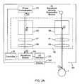
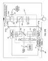
- FIG. 3Ais a schematic representation of the wavefront sensing components of an exemplary ophthalmic instrument according to the present invention.
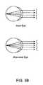
- FIG. 3Bis a schematic representation depicting the planar wavefront and distorted wavefront produced via reflection of a point source imaged onto the retina of an ideal eye and an aberrated eye, respectively.
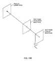
- FIG. 4is a schematic representation of the fixation target components of an exemplary ophthalmic instrument according to the present invention.
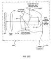
- FIG. 5is a schematic representation of the imaging components of an exemplary ophthalmic instrument according to the present invention.
- FIGS. 6A and 6Bare schematic representations of exemplary embodiments of ophthalmic instruments according to the present invention, including wavefront sensing, an internal fixation target and high resolution image capture capabilities.
- FIG. 6Cis a schematic representation of a display viewable on the display device (in addition to a keypad) of the ophthalmic instruments of FIGS. 6A and 6B, wherein the display includes a graphical representation of the aberrations of the human eye (including high order aberrations of the human eye) as measured by the wavefront sensor of the ophthalmic instrument.
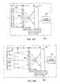
- FIGS. 7A and 7Bare functional block diagrams that illustrate a multi-stage phase compensator that is embodied as part of an adaptive optic-based ophthalmic instrument according to the present invention.
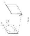
- FIGS. 8A and 8Bare pictorial illustrations of a silicon micro-machined membrane deformable mirror that may be embodied as part of the phase compensator of the adaptive optic-based ophthalmic instrument of the present invention.
- FIG. 9is a schematic illustration of exemplary Shack-Hartmann wavefront sensing components that may be embodied within the ophthalmic instruments of the present invention.
- FIG. 10Ais a functional block diagram of an exemplary embodiment of the components of imaging device 311 of FIG. 9 .
- FIG. 10Bis a functional block diagram of an exemplary embodiment of the components of image processor 310 of FIG. 9 .
- FIG. 11is a pictorial representation of the Hartmann spot pattern that is formed at approximately a lenslet focal length f L behind the lenslet array of the Shack-Hartmann wavefront sensor of FIG. 9 .
- FIG. 12is a pictorial representation of an exemplary lenslet array of the Shack-Hartmann wavefront sensor of FIG. 9, including a substantially-opaque element at the center of each lenslet of the lenslet array for use in determining the geometric reference of nominal null for the sensor.
- FIGS. 13A, 13 B, 14 A and 14 Bare pictorial illustrations of exemplary image forming and image capture components of the Shack-Hartmann wavefront sensor of FIG. 9, including a relay lens and the imaging device mounted on a linear actuator that has sufficient travel to allow the imaging device to image all planes from the plane substantially near the lenslet array itself, back to the focal plane of the longest focal length lenslet array.
- FIG. 15is a flow chart illustrating an exemplary image processing techniques that are applied to multiple images of the pupil image plane of the Shack-Hartmann wavefront sensor of FIG. 9 to thereby derive the geometric reference of the wavefront sensor.
- FIG. 16is a pictorial illustration that shows the spatial position of the system pupil (the pupil of the eye under test) in an exemplary local coordinate system used by the Shack-Hartmann wavefront sensor of FIG. 9 .
- FIG. 17is a flow chart illustrating an exemplary image processing technique that automatically locates the position of the system pupil (e.g., the pupil of the eye under test) in the local coordinate system of the Shack-Hartmann wavefront sensor of FIG. 9 .
- the system pupile.g., the pupil of the eye under test
- FIG. 18is a graphical illustration of exemplary slices (RC 1 . . . RC 8 ) from a centroid C to the periphery of an image of the pupil image plane (e.g., in the u,v pixel space), which are generated in the processing of FIG. 17 .
- FIG. 19Ais a flow chart that illustrates a mechanism, which is preferably employed by the Shack-Hartmann wavefront sensor of FIG. 9, that dynamically identifies the sub-arrays (pixel areas) of the Hartmann spot imaging device (e.g., the imaging device that will be used for the determination of Hartmann spot positions) that avoids dot crossover for a particular wavefront measurement.
- the Hartmann spot imaging devicee.g., the imaging device that will be used for the determination of Hartmann spot positions
- FIG. 19Bis a pictorial illustration of the projection of a ray from a given Hartmann spot in the spot image plane to the plane of the lenslet array of the Shack-Hartmann wavefront sensor of FIG. 9, which is used in the processing of FIG. 19 A.
- FIG. 20Aillustrates an improved Shack-Hartmann wavefront sensing head of an ophthalmic instrument according to the present invention, wherein fiducial points of the lenslet array are used to provide the geometric reference of nominal null and the delays associated with capture of the required multiple images are avoided.
- the improved Shack-Hartmann wavefront sensing headincludes a relay lens, beam splitter and multiple imaging devices that cooperate to capture images of the fiducial point image plane and the Hartmann spot imaging plane in real time in order to minimize the adverse effects of eye movement and/or accommodation on wavefront measurements performed therein.
- FIG. 20Billustrates an improved Shack-Hartmann wavefront sensing head of an ophthalmic instrument according to the present invention, wherein the image processing techniques on multiple images of the pupil image plane are used to derive the geometric reference to nominal null (as described above with respect to FIG. 15) and the delays associated with capture of the required multiple images are avoided.
- the improved Shack-Hartmann wavefront sensing headincludes a relay lens, beam splitter and multiple imaging devices that cooperate to capture images of the pupil image plane and the Hartmann spot imaging plane in real time in order to minimize the adverse effects of eye movement and/or accommodation on wavefront measurements performed therein.
- FIGS. 20C and 20Dillustrate improved Shack-Hartmann wavefront sensing heads of ophthalmic instruments according to the present invention, wherein the operations of FIG. 19 are used to dynamically identify the sub-arrays (pixel areas) of the Hartmann spot imaging device (e.g., the imaging device that will be used for the determination of Hartmann spot positions) that dot crossover for a particular wavefront measurement, and the delays associated with the capture of the required multiple images are avoided.
- the improved wavefront sensing headsinclude a beam splitter and multiple imaging devices that cooperate to capture multiple images of different planes between the lenslet array itself and the focal plane of the lenslet array as required by the operations of FIG. 19 in real time in order to minimize the adverse effects of eye movement and/or accommodation on wavefront measurements performed therein.
- FIGS. 21A-21Care pictorial illustrations of exemplary Hartmann wavefront sensors.
- FIG. 22is a flow chart illustrating an improved technique (embodied within a Hartmann wavefront sensor and ophthalmic instrument utilizing such a sensor) that determines the location of the Hartmann spot in a given pixel subaperture defined around that spot in a manner that provides better performance (e.g., a lower threshold signal-to-noise ratio) under such real-world conditions.
- an improved techniqueembodied within a Hartmann wavefront sensor and ophthalmic instrument utilizing such a sensor
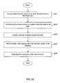
- FIG. 23is a flow chart illustrating exemplary operations of an ophthalmic instrument that provides more efficient and effective prescription of corrective optics (e.g., classes or contact lens) by measuring the aberrations (including higher order aberrations) of the eye(s) of a patient, identifying a set of prescriptions that correspond to the measured aberrations of the eye(s), and providing the patient with a view of correction (e.g., compensation) provided by the prescriptions in the set to thereby enable instant patient feedback and patient selection of the best prescription (if necessary).
- corrective opticse.g., classes or contact lens
- FIG. 24Ais a pictorial illustration of a system that provides more efficient and effective dispensing of corrective optics (e.g., classes or contact lens) by: measuring the aberrations (including higher order aberrations) of the eye(s) of a patient, identifying a set of corrective optics that correspond to the measured aberrations of the eye(s), and providing the patient with a view of correction (e.g., compensation) provided by the corrective optics in the set to thereby enable the patient to select the optimal corrective optic (if necessary) with minimal assistance.
- the systempreferably includes an imaging and dimension subsystem that generates a profile of the dimensions (and/or other relevant spatial characteristics) of the face and head of the patient.
- a set of frames that correspond to the patient's profileare identified to enable the patient to select one of the frames in the set.
- the patient selected corrective optics and frame(which may be custom built) are integrated into glasses and provided to the patient, thereby providing the patient with a frame that is optimally fitted to the dimension of the patient's head and face and with corrective optics that optimally compensate for the aberrations of patient's eyes.
- FIG. 24Bis a flow chart that illustrates the operations of the system of FIG. 24A that provides the dispensing of corrective optics (e.g., glasses or contact lens) with minimal human assistance to the patient.
- corrective opticse.g., glasses or contact lens
- FIG. 25Ais a schematic illustration of typical Hartmann wavefront sensors.
- FIG. 25Bis a schematic illustration of an improved Hartmann wavefront sensor for use in an ophthalmic instrument according to the present invention, which includes an extended source that improves the signal-to-noise ratio of the wavefront measurements calculated therein.
- FIG. 26is a functional block diagram that illustrates image correlation techniques in the digital domain that are applied to the image data that represents an image of the extended source to estimate the local tilt of the incident wavefront over a subaperture of the sensor. This technique is applied to the image data for each image of the extended source (for the plurality of images of the extended source that are formed by the subapertures of the sensor) to estimate the local tilt of the incident wavefront over the subapertures of the sensor.
- FIGS. 27A and 27Bare schematic representations of exemplary ophthalmic instruments that embody the improved Hartmann wavefront sensor of FIG. 25B according to the present invention.
- the ophthalmic instrumentsproject an image of an extended source onto the retina of the eye(s), capture a plurality of images of the extended source (derived from the retinal reflections of the projected extended source that are formed by the subapertures of the sensor), and apply image correlation techniques in the digital domain to image data derived from the plurality of images of the extended source in order to estimate the local tilt of such retinal reflections.
- the local tilt estimatesare reconstructed to form data representative of the aberrations (including defocus, spherical aberration, coma, astigmatism in addition to other higher order aberrations) of such retinal reflections, which are characteristic of the aberrations of the eye(s) of the patient.
- the ophthalmic instrument of FIG. 27Bprovides wavefront sensing, an internal fixation target, and high resolution image capture capabilities according to the present invention.
- an ophthalmic instrumentincludes an adaptive optic subsystem that forms an image of a wavefront sensing illumination source on the retina of the eye under examination, which is reflected (thereby exiting the pupil of the eye as distorted wavefronts) and directed back to the instrument.
- An image of the reflected wavefronts(which represent retroreflection of the image formed on the retina and exit the pupil of the eye as distorted wavefronts) is created on a phase compensator (which preferably comprises a variable focus lens and a deformable mirror) and recreated at a wavefront sensor.
- the phase compensatoroperates to spatially modulate the phase of the image of the distorted wavefronts incident thereon.
- the wavefront sensormeasures the phase aberrations in the wavefronts incident thereon and operates in a closed-loop fashion with a controller to control the phase compensator to compensate for such phase aberrations to restore the distorted wavefronts to phase-aligned wavefronts, which are directed to the wavefront sensor (for further wavefront measurement and compensation if required).
- the wavefront sensor and phase compensatorcompensate for the phase aberrations of the eye under examination.
- the aberrations of the distorted wavefront measured by the wavefront sensorare characteristic of the aberrations of the eye.
- the wavefront sensoris preferably operably coupled to a display device that generates a graphical representation (such as a wavefront map that depicts the OPD over the pupil, e.g., subapertures, of the wavefront sensor, or a graphical display of the coefficients of the OPD function) of the aberrations of the eye as measured by the wavefront sensor.
- a graphical representationsuch as a wavefront map that depicts the OPD over the pupil, e.g., subapertures, of the wavefront sensor, or a graphical display of the coefficients of the OPD function
- phase compensatorwhich operates to spatially modulate the phase of the image of the fixation target incident thereon to compensate for the aberrations of the eye under examination.
- the phase compensated image of the fixation target produced by the phase compensatoris created at the pupil of the eye under examination. This operation provides the patient with a view of correction (e.g., compensation) of the aberrations of the eye under examination, such the patient can provide instant feedback as to the accuracy of the measurement.
- the ophthalmic instrumentmay perform imaging operations whereby light from an imaging illumination source is directed onto the pupil of the eye, which is reflected and directed back to the instrument. An image of these reflections is created on the phase compensator, which operates to spatially modulate the phase of this image to compensate for the aberrations of the eye under examination.
- An imaging devicecaptures an image of the phase-aligned reflections output from the phase compensator. This operation provides the capture (and subsequent processing and display) of high-resolution images of the eye under examination.
- the present inventionis broadly applicable to (and can be embodied within) ophthalmic examination instruments that characterize the optical aberrations of the eye, such as phoropters and autorefractors.
- ophthalmic examination instrumentssuch as phoropters and autorefractors
- ophthalmic imaging instrumentsthat capture images of the eye (such as fundus cameras, corneal topographers, retinal topographers, corneal imaging devices, and retinal imaging devices).
- the wavefront sensing componentsinclude a wavefront sensing illumination source 51 (e.g., a ring of infrared laser diodes with a characteristic wavelength, for example, of 780 nm) that cooperates with optical elements 59 to form an image of the wavefront sensing illumination source 51 on the retina of the eye 1 , which is reflected (and exits the pupil of the eye as distorted wavefronts) and directed back to the instrument.
- a wavefront sensing illumination source 51e.g., a ring of infrared laser diodes with a characteristic wavelength, for example, of 780 nm
- the light produced from the wavefront sensing illumination source 51forms substantially planar (e.g., phase-aligned) wavefronts that are directed to the pupil of the eye. These planar wavefronts are imaged onto the retina of the eye by the crystalline lens.
- the image formed on the retinamay be a point source image.
- the image formed on the retinamay be an extended source image.
- the light reflected from the retina of an ideal eyeforms planar wavefronts at the pupil of the human eye as it leaves the human eye, while the light reflected from the retina of an aberrated eye forms distorted wavefronts at the pupil of the human eye as it leaves the human eye.
- the human eyeis not ideal and has some form of aberrations such as defocus (which may be myopia (nearsightedness) or hyperopia (far-sightedness)) and astigmatism as well has many other higher order optical aberrations.
- the optical elements 59 of the instrument 50create an image of the reflected wavefronts (which represent retroreflection of the image formed on the retina and exit the pupil of the eye as distorted wavefronts) on a phase compensator 53 , which spatially modulates the phase of the image of the reflected wavefronts incident thereon to produce a compensated image of such reflected wavefronts.
- the optical elements 59recreate this compensated image at the wavefront sensor 55 .
- the wavefront sensor 55measures the phase aberrations in the wavefronts incident thereon and operates in a closed-loop fashion with a controller 57 to control the phase compensator 53 to compensate for such phase aberrations to restore the distorted wavefronts to phase-aligned wavefronts, which are directed to the wavefront sensor 55 (for further wavefront measurement and compensation if required).
- Exemplary control schemesthat may be implemented by the controller 57 to control the phase compensator 53 to compensate for such phase aberrations are described by Tyson in “Introduction to Adaptive Optics,” SPIE Press, 2000, pgs. 93-109.
- the aberrations of the distorted wavefront measured by the wavefront sensor 55are characteristic of the aberrations of the eye 1 .
- the wavefront sensor 55is preferably operably coupled (for example, via I/O interface 121 ) to a display device 123 that generates a graphical representation (such as a wavefront map that depicts the OPD over the pupil, e.g., subapertures, of the wavefront sensor, or a graphical display of the coefficients of the OPD function) of the aberrations of the eye 1 as measured by the wavefront sensor 55 .
- a graphical representationsuch as a wavefront map that depicts the OPD over the pupil, e.g., subapertures, of the wavefront sensor, or a graphical display of the coefficients of the OPD function
- the optical elements 59 of the instrument 50preferably include a first polarizing beam splitter 59 and relay lens pair 61 / 63 that: i) form the image of a wavefront sensing illumination source 51 on the retina of the eye 1 , which is reflected (and exits the pupil of the eye as distorted wavefronts) and directed back to the instrument; and ii) direct the reflected wavefronts to a second polarizing beam splitter 65 to create an image of the reflected wavefronts at a phase compensator 53 .
- the phase compensator 53under control of controller 57 , operates to spatially modulate the phase of the image of the reflected wavefronts incident thereon to produce a compensated image of such reflected wavefronts that compensate for the aberrations of the eye under examination.
- the second polarizing beam splitter 65 and relay lens pair 67 / 69recreate this compensated image produced by the phase compensator 53 at the wavefront sensor 55 for wavefront sensing.
- the fixation target componentsinclude an internal fixation target 71 (e.g., a visible image source) that cooperates with optical elements 73 to create an image of the internal fixation target 71 at the phase compensator 53 .
- the phase compensator 53under control of controller 57 , operates to spatially modulate the phase of the image of the fixation target 71 incident thereon to compensate for the aberrations of the eye under examination as measured by the wavefront sensor 55 .
- the optical elements 73recreate the phase compensated image of the fixation target 71 produced by the phase compensator 53 at the pupil of the eye 1 under examination. This operation provides the patient with a view of correction (e.g., compensation) of the aberrations of the eye 1 under examination such the patient can provide instant feedback as to the accuracy of the measurement.
- the optical elements 73 of the instrument 50preferably include a relay lens pair 77 / 79 and first polarizing beam splitter 79 that: i) form an image of the fixation target 71 at the phase compensator 53 ; and ii) direct the phase compensated image of the fixation target 71 as produced by the phase compensator 53 to a second polarizing beam splitter 81 .
- the second polarizing beam splitter 81 and relay lens pair 83 / 83create an image of the phase compensated fixation target at the pupil of the eye 1 under examination.
- the imaging componentsinclude an imaging illumination source 87 (e.g., halogen flash lamp or xenon flash lamp) that cooperates with optical elements 90 to: i) direct light produced from the imaging illumination source 87 onto the pupil of the eye 1 , which is reflected and directed back to the instrument; and ii) create an image of these reflections on the phase compensator 53 .
- the phase compensator 53under control of controller 57 , operates to spatially modulate the phase of such images to compensate for the aberrations of the eye 1 as measured by the wavefront sensor 55 .
- the optical elements 90recreate these phase compensated images produced by the phase compensator 53 at imaging device 89 (such as a CCD camera body, 3-CCD camera body, CMOS camera body and/or a photographic film unit) for capture.
- imaging device 89such as a CCD camera body, 3-CCD camera body, CMOS camera body and/or a photographic film unit
- An image storage and output devicemay be operably coupled to the imaging device 89 to thereby store the image data captured by the imaging device 89 .
- the image storage and output devicemay communicate (for example, over a high speed serial link such as a USB bus) with an image processing and/or display apparatus (not shown) to output the image data stored therein for display, printing and image processing operations performed by the image processing and display apparatus.
- the optical elements 90 of the instrument 50preferably include a first polarizing beam splitter 91 and relay lens pair 93 / 95 that: i) direct light produced from the imaging illumination source 87 onto the pupil of the eye 1 , which is reflected and directed back to the instrument; and ii) direct the reflected wavefronts to a second polarizing beam splitter 97 to thereby create an image of the reflected wavefronts on a phase compensator 53 .
- the second polarizing beam splitter 97 and relay lens pair 98 / 99recreate the phase compensated image produced by the phase compensator 53 at imaging device 89 for capture.
- FIG. 6Athere is shown, in schematic form, an exemplary embodiment of an ophthalmic instrument 50 ′ according to the present invention, that provides wavefront sensing, an internal fixation target and high resolution image capture capabilities.
- Wavefront sensingis provided by a wavefront sensing illumination source 51 (e.g., a ring of infrared laser diodes with an characteristic wavelength, for example, of 780 nm) that cooperates with lens 125 , beam combiner 129 , first polarizing beam splitter/quarter wave plate 103 / 105 and first relay lens group LG 1 to form an image of the wavefront sensing illumination source 51 on the retina of the eye 1 , which is reflected (and exits the pupil of the eye as distorted wavefronts) and directed back to the instrument.
- a wavefront sensing illumination source 51e.g., a ring of infrared laser diodes with an characteristic wavelength, for example, of 780 nm
- the first relay lens group LG 1 , first polarizing beam splitter/quarter wave plate 103 / 105 and second polarizing beam splitter/quarter wave plate 109 / 111create an image of these distorted wavefronts on phase compensator 53 .
- the phase compensator 53operates to spatially modulate the phase of the image of the wavefronts incident thereon.
- the second polarizing beam splitter/quarter wave plate 109 / 111 , dielectric filter 113 , beam folding mirror 117 , beam splitter 117 and second relay lens group LG 2recreate the compensated wavefronts produced by the phase compensator 53 at wavefront sensor 55 .
- the dielectric filter 113operates to selectively reflect the band of light (e.g., infrared light with an characteristic wavelength, for example, of 780 nm) provided by the wavefront sensing illumination source 51 (and used for wavefront sensing) in addition to the band of light provided by the imaging illumination source 97 (and used for image capture), while passing the band of light provided by the fixation target 71 .
- the band of lighte.g., infrared light with an characteristic wavelength, for example, of 780 nm
- the wavefront sensor 55measures the phase aberrations in the wavefronts incident thereon (which are derived from retinal reflections of the wavefront sensing illumination source 51 ) and operates in a closed-loop fashion with controller 57 to control the phase compensator 53 to spatially modulate the phase of the image of the wavefronts incident thereon to compensate for such phase aberrations thereon to thereby restore the distorted wavefronts to phase-aligned wavefronts, which are directed to the wavefront sensor 55 (for further wavefront measurement and compensation if required).
- the wavefront sensor 55is preferably operably coupled (for example, via I/O interface 121 ) to a display device 123 that generates a graphical representation of the aberrations of the eye 1 as measured by the wavefront sensor 55 .
- the graphical representation of the aberrations of the eye 1 displayed by the display device 123may be a wavefront map that depicts the OPD over the pupil, e.g., subapertures, of the wavefront sensor, or a graphical display of the coefficients of the OPD function as illustrated in FIG. 6 C.
- An internal fixation target 71(e.g., a visible image source) cooperates with a third relay lens group LG 3 , dielectric filter 113 , and second polarizing beam splitter/quarter wave plate 109 / 111 to create an image of a fixation target 71 at the phase compensator 53 .
- the phase compensator 53under control of controller 57 , operates to spatially modulate the phase of the image of the fixation target 71 to compensate for the aberrations of the eye under examination as measured by the wavefront sensor 55 .
- the second polarizing beam splitter/quarter wave plate 109 / 111 , first polarizing beam splitter/quarter wave plate 103 / 105 , and first lens group LG 1recreate the phase compensated image of the fixation target 71 produced by the phase compensator 53 at the pupil of the eye 1 under examination.
- This operationprovides the patient with a view of correction (e.g., compensation) of the aberrations of the eye 1 under examination such the patient can provide instant feedback as to the accuracy of the measurement.
- Image captureis provided by an imaging illumination source 87 (e.g., halogen or xenon flash lamp) that cooperates with lens 127 , beam combiner 129 , first polarizing beam splitter/quarter wave plate 103 / 105 , and first lens group LG 1 to direct light produced from the imaging illumination source 87 onto the pupil of the eye 1 , which is reflected and directed back to the instrument.
- the first lens group LG 1 , first polarizing beam splitter/quarter wave plate 103 / 105 , and second polarizing beam splitter/quarter wave plate 109 / 111create an image of these reflections on the phase compensator 53 .
- the phase compensator 53under control of controller 57 , operates to spatially modulate the phase of such images to compensate for the aberrations of the eye 1 as measured by the wavefront sensor 55 .
- the second polarizing beam splitter/quarter wave plate 109 / 111 , dielectric filter 113 , beam folding mirror 117 , beam splitter 117 and fourth relay lens group LG 4recreate the compensated image of such reflected wavefronts as produced by the phase compensator 53 at imaging device 89 (such as a CCD camera body, integrating CCD camera body, CMOS camera body and/or a photographic film unit) for capture. This operation provides the user with the capability of acquiring high resolution images of the eye 1 .
- spectral filters that are tuned to the wavelength of the wavefront sensing illumination source 51 and/or imaging illumination source 87may be disposed along the optical path between the beam splitter 117 and the wavefront sensor 55 and imaging device 89 , respectively, in order to reduce background noise and noise from the other illumination sources of the instrument.
- FIG. 6Bthere is shown, in schematic form, an exemplary embodiment of an ophthalmic instrument 50 ′′ according to the present invention, that provides wavefront sensing, a fixation target and high resolution image capture capabilities.
- Wavefront sensingis provided by a wavefront sensing illumination source 51 (e.g., a ring of infrared laser diodes with an characteristic wavelength, for example, of 780 nm) that cooperates with lens 125 , beam combiner 129 , first polarizing beam splitter/quarter wave plate 103 ′/ 105 ′ and first relay lens group LG 1 to form an image of a wavefront sensing illumination source 51 on the retina of the eye 1 , which is reflected (and exits the pupil of the eye as distorted wavefronts) and directed back to the instrument.
- a wavefront sensing illumination source 51e.g., a ring of infrared laser diodes with an characteristic wavelength, for example, of 780 nm
- the first relay lens group LG 1 , first polarizing beam splitter/quarter wave plate 103 ′/ 105 ′ and second polarizing beam splitter/quarter wave plate 109 ′/ 111 ′create an image of the distorted wavefronts on a phase compensator 53 .
- the phase compensator 53operates to spatially modulate the phase of the wavefronts incident thereon.
- the second polarizing beam splitter/quarter wave plate 109 ′/ 111 ′, dielectric filter 114 , beam splitter 117 ′ and second relay lens group LG 2recreate the image of such compensated wavefronts at wavefront sensor 55 .
- the dielectric filter 114operates to selectively reflect the band of light provided by the fixation target 71 , while passing the band of light (e.g., infrared light with an characteristic wavelength, for example, of 780 nm) provided by the wavefront sensing illumination source 51 (and used for wavefront sensing) in addition to the band of light provided by the imaging illumination source 97 (and used for image capture).
- the band of lighte.g., infrared light with an characteristic wavelength, for example, of 780 nm
- the wavefront sensor 55measures the phase aberrations in the wavefronts incident thereon (which are derived from retinal reflections of the wavefront sensing illumination source 51 ) and operates in a closed-loop fashion with a controller 57 to control the phase compensator to spatially modulate the phase of the wavefronts incident thereon to compensate for such phase aberrations (by warping it's surface to form the complex conjugate of the measured errors) to thereby restore the distorted wavefronts to phase-aligned wavefronts, which are directed to the wavefront sensor 55 (for further wavefront measurement and compensation if required).
- the wavefront sensor 55is preferably operably coupled (for example, via I/O interface 121 ) to a display device 123 that generates a graphical representation of the aberrations of the eye 1 as measured by the wavefront sensor 55 .
- the graphical representation of the aberrations of the eye 1 displayed by the display device 123may be a wavefront map that depicts the OPD over the pupil, e.g., subapertures, of the wavefront sensor, or a graphical display of the coefficients of the OPD function as illustrated in FIG. 6 C.
- the fixation targetis provided by an internal fixation target 71 (e.g., a visible image source) that cooperates with a third relay lens group LG 3 , dielectric filter 114 , and second polarizing beam splitter/quarter wave plate 109 ′/ 111 ′ to create an image of the internal fixation target 71 at the phase compensator 53 .
- the phase compensator 53under control of controller 57 , operates to spatially modulate the phase of the image of the fixation target 71 to compensate for the aberrations of the eye under examination as measured by the wavefront sensor 55 .
- the second polarizing beam splitter/quarter wave plate 109 ′/ 111 ′, first polarizing beam splitter/quarter wave plate 103 ′/ 105 ,′ and first lens group LG 1recreate the phase compensated image of the fixation target 71 produced by the phase compensator 53 at the pupil of the eye 1 under examination.
- This operationprovides the patient with a view of correction (e.g., compensation) of the aberrations of the eye 1 under examination such the patient can provide instant feedback as to the accuracy of the measurement.
- Image captureis provided by an imaging illumination source 87 (e.g., halogen or xenon flash lamp) that cooperates with lens 127 , beam combiner 129 , first polarizing beam splitter/quarter wave plate 103 ′/ 105 ′, and first lens group LG 1 to direct light produced from the imaging illumination source 87 onto the pupil of the eye, which is reflected and directed back to the instrument pupil.
- the first lens group LG 1 , first polarizing beam splitter/quarter wave plate 103 ′/ 105 ′, and second polarizing beam splitter/quarter wave plate 109 ′/ 111 ′create an image of these reflections on the phase compensator 53 .
- the phase compensator 53under control of controller 57 , operates to spatially modulate the phase of such images to compensate for the aberrations of the eye 1 as measured by the wavefront sensor 55
- the second polarizing beam splitter/quarter wave plate 109 ′/ 111 ′, dielectric filter 114 , beam splitter 117 ′ and fourth relay lens group LG 4recreate the compensated image of such reflected wavefronts as produced by the phase compensator 53 at imaging device 89 (such as a CCD camera body, 3-CCD camera body, CMOS camera body and/or a photographic film unit) for capture. This operation provides the user with the capability of acquiring high resolution images of the eye 1 .
- spectral filters that are tuned to the wavelength of the wavefront sensing illumination source 51 and/or imaging illumination source 87may be disposed along the optical path between the beam splitter 117 ′ and the wavefront sensor 55 and imaging device 89 , respectively, in order to reduce background noise and noise from the other illumination sources of the instrument.
- the ophthalmic instrument of the present inventionpreferably includes the following components (which, while not shown in the Figures in order to simplify the diagram, are assumed provided in the system described herein):
- Headband and chinrestthe patient is positioned at the instrument with his forehead against the band and his chin in the chinrest.
- Chinrest adjusting knobthe vertical distance between the forehead band and the chinrest is adjusted with this knob.
- Fixation Target Control knob(s)controls the working distance (and possibly lateral movement in the plane perpendicular to the optical axis) of the instrument, and possibly size (i.e., scale)) of the internal fixation target 71 .
- the working distance of the internal fixation target 71is set to infinity in order to limit the accommodation of the eye during wavefront sensing, and/or imaging operations.
- the wavefront sensor 55 of the ophthalmic instrument of the present inventionpreferably comprises a Shack-Hartmann wavefront sensor, which includes an array of small lenslets disposed in front of an imaging device (such as a CCD camera body, integrating CCD camera body or CMOS camera body).
- the lensletspartition the incident wavefront into a large number of smaller wavefronts, each of which is focused to a small spot on the imaging device.
- the spatial location of each spotis a direct measure of the local tilt (sometimes referred to as local slope or local gradient) of the incident wavefront.
- the Shack-Hartmann wavefront sensorincludes signal processing circuitry (for example, a digital signal processor) that samples the output of the imaging device and processes the data output there from to track the spatial positions of these spots to derive the local tilt (e.g., local gradients) of the incident wavefronts.
- signal processing circuitryfor example, a digital signal processor
- These local gradientsare reconstructed to form data representative of the aberrations of the distorted wavefronts (including defocus, spherical aberration, coma, astigmatism in addition to other higher order aberrations of the distorted wavefronts).
- the local gradientsmay be reconstructed into an optical path difference (OPD) array, which stores a scalar value that represents the optical path difference at each lenslet.
- OPDoptical path difference
- the local gradientsmay be reconstructed into an OPD function, for example, by minimizing the difference between the derivatives of an analytical function (such as a set of Zernike polynomials, Seidel polynomials, Hermites polynomials, Chebychev polynomials, and Legendre polynomials) and the measured local gradients.
- an analytical functionsuch as a set of Zernike polynomials, Seidel polynomials, Hermites polynomials, Chebychev polynomials, and Legendre polynomials
- Shack-Hartman wavefront sensor configurationsare described below. Alternate wavefront sensing techniques are described in detail in Geary, “Introduction to Wavefront Sensors”, SPIE Optical Engineering Press, 1995, pp. 53-103.
- the wavefront sensor 55may comprise a Tscherning wavefront analyzer that illuminates the eye with a dot pattern formed by a laser source and dot pattern mask.
- the reflected dot patternis captured by the imaging device and the image data is analyzed to derive deviations in the dot pattern from its ideal locations. From the resulting deviations, aberrations in the distorted wavefronts produced from the subject eye are mathematically reconstructed.
- a more detailed description of a Tscherning wavefront analyzeris described by Mierdel et al. in “A measuring device for the assessment of monochromatic aberrations of the eye,” Ophthamologe, 1997, Vol. 94, pgs. 441-445, and Mrochen et al., “Principles of Tscherning Aberrometry,” J of Refractive Surgery, Vol. 16, Sep./Oct. 2000.
- the wavefront sensor 55may comprise a spatially resolved refractometer as described in detail by He et al. in “Measurement of the wave-front aberration of the eye by fast psychophysical procedure,” J Opt Soc Am A, 1998, Vol. 15, pgs. 2449-2456 and in U.S. Pat. Nos. 5,258,791 and 6,000,800, each incorporated herein by reference in its entirety.
- the wavefront sensor 55may comprise any one of the improved wavefront sensor configurations described below in conjunction with FIGS. 20A-20D or FIG. 22, or FIGS. 25B, 26 , 27 A and 27 B.
- the wavefront sensor 55measures the aberrations (including defocus, spherical aberration, coma, astigmatism in addition to other higher order aberrations) of the distorted wavefronts (produced by retinal reflection of light produced by the wavefront sensing illumination source 51 ).
- the aberrations measured by the wavefront sensor 55represent the aberrations of the subject eye (including high order aberrations of the eye such as spherical aberration, astigmatism and coma).
- the wavefront sensor 55supplies data representative of these aberrations (such as an OPD array or OPD function) to the controller 57 , which controls the phase compensator 53 to restore the distorted wavefronts (which are derived from retinal reflections of the wavefront sensing illumination source 51 ) to phase-aligned wavefronts, which are directed to the wavefront sensor 55 (for further wavefront measurement and compensation if required).
- data representative of these aberrationssuch as an OPD array or OPD function
- the phase compensator 53 embodied within the adaptive optic subsystem of an ophthalmic instrumentpreferably comprises multiple stages (such as the variable focus lens (VFL) and a deformable mirror as shown) that compensate for different parts of the aberrations of the eye 1 as estimated by the wavefront sensor 55 .
- the wavefront sensor 55or the controller 57 ) can decompose such aberrations into a defocus component (which represents the defocus of the eye 1 ) and one or more additional components which represent the higher order components (e.g., spherical aberration, astigmatism and coma) of such aberrations.
- controller 57controls the first stage (i.e., the variable focus lens) to compensate for the defocus component of such aberrations, and controls the one or more additional stages (i.e., a deformable mirror) to compensate for the remaining higher order components of such aberrations.
- a deformable mirrorachieves such compensation by warping its optical surface to form the complex conjugate of such higher order components as measured by the wavefront sensor 55 .
- the variable focus lensmay comprise a stationary first lens 1 , and a second lens 2 that is moved linearly with respect to the first lens along the optical axis of the first and second lens and deformable mirror by an actuator a shown.
- Silicon micro-machined membrane mirrors(which is a class of deformable mirrors that are readily available, for example, from OKO Technologies of Deelft, the Netherlands) are suitable for phase compensation for many ophthalmic imaging applications.
- such mirrorstypically consist of a silicon chip 601 mounted over a printed circuit board substrate 603 by spacers 605 .
- the top surface 607 of the chip 603contains a membrane (typically comprising silicon nitride) which is coated with a reflective layer (such as aluminum or gold) to form the mirror surface.
- the printed circuit board 603contains a control electrode structure (as illustrated in FIG. 8B) that operates to deform the shape of the reflective membrane by applying bias and control voltages to the membrane and the control electrodes 609 .
- deformable mirrorsincluding segmented mirrors, continuous faceplate mirrors, and edge actuated mirrors
- phase compensation for many ophthalmic applicationsare described by Tyson in “Introduction to Adaptive Optics,” SPIE Press, 2000, pgs. 83-91, supra.
- classes of liquid crystal devicesare suitable for phase compensation for many ophthalmic applications.
- Proper alignment (and focus) of the optical elements of the ophthalmic instrument 50is required for optimal operations.
- proper alignment of the eye 1 to the ophthalmic instrument 50is also required for optimal operations.
- alignment of the optical elements of ophthalmic instrument 50is accomplished by user manipulation of one or more control levers (or joystick(s)) that control forward/backward, side-to-side, and vertical alignment of the optical elements of the instrument 50 .
- Gross alignment of the instrument 50is preferably accomplished by sliding the base of the instrument 50 in the desired direction.
- Focus of the instrument 50is preferably controlled by one or more focusing knobs that cooperate with the optical elements of the instrument to adjust focus of the instrument 1 .
- Proper alignment of eye 1 to the instrument 50may be accomplished with a headband and chin rest whereby the patient is positioned at the instrument 50 with his/her forehead against the headband and his/her chin in the chinrest.
- One or more adjusting knobsmay be used to adjust the position of the subject eye such that it is properly aligned with the optical axis of the instrument 50 .
- the position (and orientation) of the instrument 50may be changed such that it is properly aligned with the eye 1 . This step is suitable for handheld ophthalmic devices.
- Such alignmentis preferably accomplished through the use of cross-hairs and an infrared distance detector embodied within the instrument 50 .
- the cross-hairsare centered in the field of view of the instrument 50 and viewable to the user such that the user can accurately position the cross hairs onto the pupil of the eye 1 .
- the infrared distance detectorprovides visible feedback (i.e., varying frequency flicker lights) or audible feedback (different pitched beeps) that enables the user to accurately position and orient the optical axis of the instrument 50 with respect to the eye 1 .
- FIG. 9illustrates exemplary Shack-Hartmann wavefront sensing components that can embodied within the ophthalmic instruments of the present invention.
- these componentsinclude foreoptics 301 and a wavefront sensor head 303 .
- the foreoptics 301which preferably include a beam combiner 304 and collimating lens 305 as shown, operate in conjunction with the optical elements of the instrument to form an image of the distorted wavefronts (which are formed via reflection of the image of the wavefront sensing illumination source 51 on the retina of the eye 1 ) in the plane of a lenslet array 307 .
- the lenslet array 307partitions the incident wavefront into a large number of smaller wavefronts and forms corresponding focal spots (e.g., Hartmann spot pattern).
- a relay lens 309images the Hartmann spot pattern on an imaging device 311 (such as a CCD camera body, a CMOS camera body, or an integrating CCD camera body).
- the imaging device 311is operably coupled to an image processor 310 that grabs the image data captured by the imaging device 311 , processes the grabbed image data to track spot movement in the Hartmann spot pattern, derives a measure of the local tilt of the distorted wavefronts at the lenslets from such test spot movements, and possibly stores such image data in persistent storage.
- the image processor 310generates data (such as an OPD array or OPD function) representative of the aberrations of the distorted wavefronts (including defocus, spherical aberration, coma, astigmatism in addition to other higher order aberrations of the distorted wavefronts) from such measures.
- datasuch as an OPD array or OPD function
- datais provided to a controller which controls a phase-compensating optical element(s) to compensate for such phase aberrations to restore the distorted wavefronts to phase-aligned wavefronts.
- FIG. 10Aillustrates an exemplary embodiment of the components of imaging device 311 of FIG. 9, including a CCD array 811 of photodetectors that detect the intensity of incident light thereon and generate an electrical signal in response thereto, timing and control circuitry 813 that supply timing signals to the CCD array 811 to: read out the electrical signals generated by the elements therein, store the signals in buffer 815 , output the signals stored in buffer 815 to signal processing circuitry 817 that condition such signals for analogue-to-digital conversion circuitry 819 , and store digital data words (pixel data words) derived from such signals in digital buffer and output circuitry 821 for output to image processing.
- a CMOS array or integrating CCD arraymay be substituted for the CCD array 811 .
- FIG. 10Billustrates an exemplary embodiment of the components of image processor 310 of FIG. 9, including a memory controller 853 that provides access to memory 855 for interface 851 , digital signal processor 857 .
- Interface 851inputs pixel data words from the imaging device 311 and stores such pixel data words in memory 855 via memory controller 853 .
- the digital signal processor 857accesses the pixel data stored in memory 855 and processes such data in accordance with a sequence of programmed instructions.
- the memory controller 853also communicates with an I/O interface to thereby display data on a display device (such as a TFT LCD device).
- the Hartmann spot patternis formed at approximately a lenslet focal length f L behind the lenslet array 307 .
- relay lens 309it is desirable to use relay lens 309 to relay the Hartmann spot pattern onto the imaging device 311 .
- thisallows the matching of the scale of the Hartmann spot pattern to the pixel size of the imaging device 311 .
- the wavefront sensor head 303to gather a much wider range of data on the optical system under test and, as a result, make measurements of greater accuracy.
- the relay lens 309operates in a telecentric mode to minimize the possibility of magnification errors that lead to wavefront estimation errors.
- the lenslet array 307may be of the type manufactured and sold by Adaptive Optics Inc, of Cambridge, Mass., assignee of the present invention, in that it comprises a precision array of refractive microlenses formed continuously on a monolithic substrate.
- the array of microlensesare preferably compression molded of polymethymethacrylate (PMMA) plastic, and positioned in the substrate with full edge-to-edge lenslet contact to maximize the density of lens area to total surface area (referred to as “fill factor”).
- the fill factordetermines how much of the scaled full aperture system pupil (the subject eye under examination) is captured by the array.
- the commercial lenslet arrays manufactured and sold by assignee of the present inventionhave fill factors exceeding 98 percent.
- the Shack-Hartmann wavefront sensing head 303derives local wavefront tilt at a given lenslet from spot motion for the given lenslet.
- Such derivationinherently depends upon the particular geometry of the sensor head and its optics (including the distance between the pupil image plane and the spot image plane, the radius of the pupil of the lenslet, and possibly the refractive index of the lenslet) and requires a geometric reference of the nominal null (i.e., spot location corresponding to incident of a planar wavefront on a given lenslet).
- a more detailed description of the derivation for relating spot motion to local wavefront tiltis described in detail by Geary in “Introduction to Wavefront Sensors”, SPIE Optical Engineering Press, 1995, pp. 14-20.
- the distance between the pupil image plane and the spot image plane and the radius of the pupil of the lenslet(which is set by the size of the individual lenslet elements) are both quantities that are determined at the time of manufacture, this basic parameters need not be re-measured each time the system is used.
- parameters related to a particular wavefront measurementthat must be determined before that particular wavefront measurement can be made.
- These parametersinclude the geometric reference of nominal null and, possibly, the position and shape of the system pupil (e.g., the pupil of the eye under test) in the local coordinate system of the wavefront sensing head 303 .
- the shape of the system pupilis primarily used for the calculation of polynomial decompositions of the wavefront. For example, Zernike and Seidel polynomial decompositions are derived from a circular pupil, whereas Monomials, Hermites, Chebychev, and Legendre polynomial decompositions are derived from a rectangular pupil.
- selection of the pupil shapehas no direct effect on the wavefront measurement itself. In cases where there is no well defined pupil, any convenient pupil may be selected.
- the Shack-Hartmann wavefront sensor(which is preferably embodied within the ophthalmic instruments of the present invention) may utilize one of a number of different approaches in achieving the geometric reference to nominal null.
- a first approachachieves this geometric reference by a reference plane wave (generated by a laser source and suitable collimating optical elements) that is recreated at the plane of the lenslet array 307 .
- the Hartmann spot patternwhich is formed at approximately a lenslet focal length f L behind the lenslet array 307 , is captured by imaging device 311 .
- the image processor 310is controlled to grab the image captured by the imaging device 311 and process this image to derive reference spot locations (based upon the centroid of the spots therein).
- deviation of Hartmann spot locationis measured to derive an estimate of the phase aberration in the wavefront sampled by the corresponding lenslet.
- This first approachis costly because the flat wave signal source and collimating optics must be of high optical quality.
- a second approachachieves this geometric reference (without the costs of a high quality flat wave signal source and collimating optics) by providing a substantially-opaque element at the center of each lenslet of the lenslet array 307 ′ as illustrated in FIG. 12 .
- the lenslet array 307 ′is illuminated with a reference beam, which is preferably produced by reference source 315 and directed to the lenslet array 307 ′ by beam combiner 304 and collimating lens 305 as shown in FIG. 9 .
- an imaging deviceis positioned conjugate the fiducial point image plane—this is the plane whereby the fiducial points appear at the imaging device as an array of fiducial reference spots exactly co-aligned with the centers of the lenslets.
- An image processoris controlled to grab the image captured by the imaging device and process this image to identify the locations of the fiducial reference spots (based upon the centroid of the fiducial reference spots). Deviation of Hartmann spot location (with respect to the recorded fiducial reference spot location) is measured during wavefront sensing operations to measure the phase aberration in the wavefront sampled by the corresponding lenslet.
- the optical components that image the reference beam onto the lenslet array 307 ′may be of lower optical quality and costs than the optical components required to provide the flat reference wave as discussed above.
- the second approachis far more stable than the first approach.
- This second approachmay be accomplished with the wavefront sensing head 303 ′ of FIGS. 13A and 13B wherein relay lens 309 ′ and the imaging device 311 ′ are mounted on a linear actuator that has sufficient travel to allow the imaging device 311 ′ to image all planes from the plane substantially near the lenslet array 307 ′ itself, back to the focal plane of the longest focal length lenslet array.
- This configurationis described in detail in U.S. Pat. No. 5,629,765, commonly assigned to the assignee of the present invention, and herein incorporated by reference in its entirety.
- location of the fiducial reference spots in the fiducial reference spot patternis accomplished by moving the relay lens 309 ′ and imaging device 311 ′ as illustrated in FIG.
- a reference beamilluminates the lenslet array 307 ′, and the image processor 310 is controlled to grab one or more images of the fiducial point image plane as captured by the imaging device 311 , and process such image(s) to identify the locations of the fiducial reference spots for each given lenslet.
- the phase aberration in the distorted wavefront sampled by a given lensletis approximated by determining the location of the Hartmann spot produced by the given lenslet relative to the location of the fiducial reference spot corresponding to the given lenslet. As illustrated in FIG. 13B, this measurement is accomplished by moving the relay lens 309 ′ and imaging device 311 ′ such that the imaging device 311 ′ is placed at one or more positions substantially near the spot image plane—this is plane whereby the focal plane of the lenslet array 307 ′ as illustrated in FIG. 11 is imaged onto the imaging device 311 .
- the distorted wavefrontis recreated at the plane of the lenslet array 307 ′, and the image processor 310 is controlled to grab one or more images substantially near the spot image plane as captured by the imaging device 311 , and process such image(s) to: (i) identify the location of the Hartmann spot corresponding to the lenslets, and (ii) compute the relative difference between this Hartmann spot location and the corresponding location of the fiducial reference spot for the lenslets.
- FIG. 15is a flow chart illustrating an exemplary embodiment of such image processing techniques.
- the lenslet array 307is illuminated by a reference source (for example, light produced by reference source 315 may be directed to the lenslet array 307 by beam combiner 304 and collimating lens 305 as shown in FIG. 9 ).
- a reference sourcefor example, light produced by reference source 315 may be directed to the lenslet array 307 by beam combiner 304 and collimating lens 305 as shown in FIG. 9 .
- the apparent distance of the reference source to the lenslet array 305is (or is near) infinity to minimize magnification changes (due to change in distance) in the first and second images of the pupil image plane as described below.
- an imaging deviceis positioned such that it captures a first image of pupil image plane that shows the edges of the lenslets as a dark grid, and an image processor is controlled to grab this first image captured by the imaging device.
- step 1503the lenslet array 307 is illuminated by the reference source; and, concurrently therewith, an imaging device is positioned such that it captures a second image of pupil image plane that shows the edges of the lenslets as a bright grid, and the image processor is controlled to grab this second image captured by the imaging device.
- step 1505the image processor generates a third composite image representing the grid (with the average signal of the first and second images removed) by subtracting the first and second images.
- the image processorcalculates the real and imaginary parts of a two-dimensional Fourier transform of the third composite image generated in step 1505 .
- Nrepresents the number of pixels in each row (i.e., x direction) of the image
- Mrepresents the number of pixels in a column (i.e., y direction) of the image
- f(x,y)represents the intensity value at a pixel (x,y) in the image
- the exponential termis the basis function corresponding to each point F(k,l) in Fourier space.
- the two-dimensional Fourier transform F(k,l)can be decomposed into a real part (R(k,l)) and an imaginary part (I(k,l)) as follows:
- step 1508the image processor calculates the magnitude and phase components of the two-dimensional dimensional Fourier transform calculated in step 1507 .
- the magnitude and phase components of the two-dimensional Fourier transform F(k,l)can be calculated as follows:
- step 1509the image processor determines the period of the grid based upon the magnitude component of the two-dimensional dimensional Fourier transform calculated in step 1508 , and determines the location of the grid based upon the phase component of the two-dimensional dimensional Fourier transform calculated in step 1508 .
- This stepis preferably accomplished as follows. First, a region around the expected first-harmonic peak (based upon the approximate spacing of the grid) in the magnitude component calculated in step 1508 is identified. Second, a function (such as a parabolic function) is fit to this region, and a maximum of this function is identified. Third, the period of a grid in both x and y direction that corresponds to this maximum is identified.
- the maximum magnitude component of the Fourier transformcorresponds to a spatial frequency that is inversely proportional to the period of the grid in both x and y direction.
- the phase component of the Fourier transform calculated in step 1508 that corresponds to this maximumis identified, and the location of the grid is calculated based upon the identified phase component.
- the identified phase componentprovides translation in both x direction and y direction from the origin of the coordinate system of the image device to the origin of the grid.
- the image processorgenerates a regular grid of lenslet center locations in the coordinate system of the imaging device based upon the location and period of the grid determined in step 1509 .
- the lenslet center locationsare offset a half cycle in both the x direction and y direction from the grid.
- the half cycle offsetcan be readily determined from period of the grid (which is inversely proportional to the maximum magnitude component of the Fourier transform).
- Such lenslet center locationsare analogous to the locations of spots of the reference spot pattern in the first approach and the fiducial point spot pattern in the second approach, thus providing the geometric reference to nominal null (i.e., spot location corresponding to incident of a planar wavefront on a given lenslet). Deviation of Hartmann spot location (with respect to the corresponding lenslet center location) is measured during wavefront sensing operations to measure the local tilt in the wavefront sampled by the corresponding lenslet.
- This approachis advantageous because it avoids the costs of a high quality flat wave signal source and collimating optics of the first approach and the costs of adding fiducial points to the lenslets of the lenslet array as described above in the second approach.
- This third approachmay be accomplished with the wavefront sensing head 303 ′′ of FIGS. 14A and 14B wherein the relay lens 309 and the imaging device 311 are mounted on a linear actuator, which preferably has sufficient travel to allow the imaging device 311 to image all planes from the plane substantially near the lenslet array 307 itself, back to the focal plane of the lenslet array.
- the imaging device 311may capture the first image in step 1501 by moving the relay lens 309 and image device 311 to a position whereby the imaging device 311 captures the pupil image plane slightly outside of best focus (i.e., the plane of the lenslet array 307 and the plane of the relay lens 309 is offset by D+ ⁇ 1 ).
- the imaging device 311may capture the second image in step 1503 by moving the relay lens 309 and image device 311 to a position whereby the imaging device 311 captures the pupil image plane slightly inside of best (i.e., the plane of the lenslet array 307 and the plane of the relay lens 309 is offset by D ⁇ 2 ).
- the image processor 310performs the operations of steps 1505 to 1511 to generate the lenslet center locations in the coordinate system of imaging device 311 .
- Position of the System Pupile.g. The Pupil of the Eye Under Test
- the wavefront measurement operations performed by the Shack-Hartmann wavefront sensorrequires calibration of the position of the system pupil (e.g., the pupil of the eye under test) in the local coordinate system of the wavefront sensing head.
- FIG. 16illustrates an exemplary local coordinate system for use by the wavefront sensing head of FIG. 9, which includes pixel coordinates (u,v) of the imaging device 311 and a distance f along the optical axis of the system.
- Such calibrationmay be fixed by design. However, this mapping is critical to successful estimation of the wavefront (and the operation of the closed-loop phase compensation system), and any errors therein are directly related to the absolute wavefront measurement error.
- the Shack-Hartmann wavefront sensoremploy a mechanism that can dynamically (and automatically without human intervention) perform such calibration.
- FIG. 17is a flow chart illustrating an exemplary image processing technique that automatically locates the position of the system pupil (e.g., the pupil of the eye under test) in the local coordinate system of the wavefront sensor. This technique can be used dynamically to perform such calibration as frequently as required to ensure the opto-mechanical stability of the system.
- This techniquecan be used dynamically to perform such calibration as frequently as required to ensure the opto-mechanical stability of the system.
- the system pupile.g., the pupil of the eye under test
- the system pupilis imaged at the plane of the lenslet array 307 (for example by the optical train of the ophthalmic instrument, beam combiner 304 and collimating lens 305 of the wavefront sensor); and, concurrently therewith, an imaging device captures an image of pupil image plane at best focus.
- an image processorprocesses the image of the pupil image plane grabbed in step 1701 to locate the centroid of the image.
- weightsare assigned to each column of pixels in the image and the measured intensity for each pixel in the image is multiplied by the weight corresponding to the column of the given pixel and summed together. If the weights vary linearly with the distance of the column from the center of the image, this sum will be a measure of the x-position of the light distribution. The sum needs to be normalized by dividing by the sum of the unweighted intensities.
- weightsare assigned to each row of pixels in image and the measured intensity for each pixel in the image is multiplied by the weight corresponding to the row of the given pixel and summed together. If the weights vary linearly with the distance of the column from the center of the image, this sum will be a measure of the y-position of the light distribution. The sum needs to be normalized by dividing by the sum of the unweighted intensities.
- i and jidentify the rows and columns, respectively, of the image
- w i and w jare the weights assigned to given rows and columns, respectively, of the image.
- I ijis the intensity of a given pixel in row i and column j of the image.
- step 1705the image processor processes the image of the pupil image plane grabbed in step 1701 to determine, for a plurality of slices (e.g., radial cuts) from the centroid (calculated in step 1703 ) to the periphery of the image, the gradient of the intensity along each slice, and the pixel location of maximum of the intensity gradient along each slice.
- FIG. 18provides a graphical illustration of exemplary slices (RC 1 . . . RC 8 ) from a centroid C to the periphery of an image of the pupil image plane (e.g., in the u,v pixel space).
- the image processorfits a predetermined shape (such as a circle, ellipse or rectangle) to the pixel locations of the maximums of the intensity gradient along the slices as calculated in step 1705 .
- This best-fit shapee.g., pixel coordinates of the center and radius in the case of a best-fit circle
- the system pupile.g., the pupil of the eye under test
- the local coordinate system of the wavefront sensing heade.g., the local coordinate system illustrated in FIG. 16
- such pixel coordinates and the distance along the optical path from the lenslet array 307 to the imaging device 311provides the (u,v,f) coordinates of the system pupil (e.g., the pupil of the eye under test).
- the calibration operations of FIG. 17may be accomplished with the wavefront sensing head 303 ′′ of FIGS. 14A and 14B wherein the relay lens 309 and the imaging device 311 are mounted on a linear actuator, which preferably has sufficient travel to allow the imaging device 311 to image all planes from the plane substantially near the lenslet array 307 itself, back to the focal plane of the lenslet array.
- the imaging device 311may capture the image of pupil image plane at best focus in step 1701 by moving the relay lens 309 and image device 311 to a position whereby the imaging device 311 captures the pupil image plane at best focus (i.e., the plane of the lenslet array 307 and the plane of the relay lens 309 is offset by D).
- the image processor 310performs the operations of steps 1703 to 1707 to locate the position of the system pupil (e.g., the pupil of the eye under test) in the local coordinate system of the wavefront sensing head.
- the Shack-Hartmann wavefront sensoremploy a mechanism that addresses dot crossover problem, which occurs when there is a predefined region of the Hartmann spot imaging plane that is used to determine location of the Hartmann spot for a given lenslet. If the spot moved outside that predefined region (i.e., dot crossover occurs), the dynamic range of the sensor is exceeded, resulting in an erroneous wavefront measurement.
- the Shack-Hartmann wavefront sensorcan employ a mechanism that dynamically identifies the sub-arrays (pixel areas) of the Hartmann spot imaging device (e.g., the imaging device that will be used for the determination of Hartmann spot positions) that avoids dot crossover for a particular wavefront measurement.
- a mechanism that dynamically identifies the sub-arrays (pixel areas) of the Hartmann spot imaging devicee.g., the imaging device that will be used for the determination of Hartmann spot positions
- a detailed description of an illustrative procedure that provides such a dynamic mechanismis described below with respect to FIG. 19 .
- step 1901the system pupil image is recreated at the lenslet array 307 and the Hartmann spot imaging device is positioned such that it captures an image of the Hartmann spot pattern (at best spot focus) as formed at the focal plane of the lenslet array; and the sub-regions (i.e., pixel areas) of the imaging device 311 , which are denoted “test subapertures” for the sake of description, that are to be used for the determination of Hartmann spot locations are defined.
- the systempreferably grabs an image of the Hartmann spot pattern and locates the position of all of the “useable” Hartmann spots in this image.
- a predetermined criterion(for example, based upon intensity values of pixels covered by a given Hartmann spot) is used to distinguish between “useable” and “unuseable” Hartmann spots and to filter out such “unuseable” Hartman spots.
- Sub-regions of the imaging device 311 around each useable Hartmann spotare defined and stored in a list of test subapertures. The sizes of these sub-regions are made as large as possible without overlapping.
- the systemdetermines if a reasonable number of “useable” Hartmann spots have been found based upon the known spacing of the lenslet array 307 and the size of the Hartmann spot imaging device. If an unreasonably low number of “useable” Hartmann spots have been found, preferably an error is reported to the user.
- each test subaperture in the list of test subaperturesis matched to a corresponding lenslet (i.e., the particular lenslet that produced the spot from which the subaperture is derived).
- This matching processpreferably is accomplished by capturing, grabbing and processing one or more additional images of the Hartmann spot pattern that are taken slightly inside (or outside) best focus. In such image(s), the location of the spot in each subaperture differs from that found in the image at best spot focus. This difference is due to any deviation of the direction of propagation from the optical axis of the lenslet.
- the positions measured in the imagesmay be used to project a ray from a given spot back to the plane of the lenslet array 307 (i.e., the ray passing through the spot positions as illustrated in FIG. 19B) to generate a list of crossing locations at this plane for each test subaperture.
- test subapertures(defined in step 1901 ) are wholly separate from the sub-regions of the imaging device that will be used for the measurement of the reference source (which are defined in step 1905 ). It is this use of separate lists of subapertures and subsequent matching process (step 1909 ) that allows the wave front sensor 303 to effectively resolve potential dot crossover problems and thus achieve very large dynamic range that includes highly aberrated eyes.
- a reference sourceilluminates the lenslet array 307 and the Hartmann spot imaging device is positioned such that it captures an image of the spot pattern (at best spot focus) formed at the focal plane of the lenslet array; and the sub-regions (i.e., pixel areas) of the imaging device, which are denoted “reference subapertures” for the sake of description, that are to be used for the determination of such spot locations are defined.
- the reference sourcemay be directed to the lenslet array 307 by beam combiner 304 and collimating lens 305 as shown in FIG. 9 .
- the systempreferably grabs an image of the spot pattern and locates the position of all of the “useable” spots in this image.
- a predetermined criterion(for example, based upon intensity values of pixels covered by a given spot) is used to distinguish between “useable” and “unuseable” spots and to filter out such “unuseable” spots.
- Sub-regions of the imaging device around each useable spotare defined and stored in a list of reference subapertures. The sizes of these sub-regions are made as large as possible without overlapping.
- the systemdetermines if a reasonable number of “useable” spots have been found based upon the known spacing of the lenslet array 307 and the size of the imaging device. If an unreasonably low number of “useable” spots have been found, preferably an error is reported to the user.
- each reference subaperture in the list of reference subaperturesis matched to a corresponding lenslet (i.e., the particular lenslet that produced the spot from which the subaperture is derived).
- This matching processpreferably is accomplished by capturing, grabbing and processing one or more additional images of this spot pattern that are taken slightly inside (or outside) best focus. In such image(s), the location of the spot in each subaperture differs from that found in the image at best spot focus. This difference is due to any deviation of the direction of propagation from the optical axis of the lenslet.
- the positions measured in the imagesmay be used to project a ray from a given spot back to the plane of the lenslet array 307 (i.e., the ray passing through the spot positions as illustrated in FIG. 19B) to generate a list of crossing locations at this plane for each reference subaperture.
- step 1909the system then processes the lists of crossing locations and the associated aperture lists to find unique reference aperture/test aperture pairs whose crossing points coincide within prescribed tolerances to a lenslet center of the lenslet array (which may be derived from the reference spot locations as described above, or from the fiducial point locations as described above with respect to FIGS. 12, 13 A, 13 B, and 14 , or from the image processing techniques described above with respect to FIGS. 15 and 16 ).
- the systemverifies that the crossing points for these unique reference aperture/test aperture pairs correspond to a single lenslet in the lenslet array. In the event that the crossing points for a particular reference aperture/test aperture pair correspond to different lenslets in the lenslet array, that particular reference aperture/test aperture pair is removed from the list.
- the ultimate result of the matching process of step 1909is a list of lenslets (or reference spot locations or fiducial point locations or lenslet centers) each uniquely associated with a given reference subaperture and test subaperture.
- the list of lenslets (or lenslet reference spot locations or lenslet fiducial point locations or lenslet centers) produced by the matching process of step 1909is used during wavefront sensing operations to provide the geometric reference of nominal null (i.e., reference spot position) for the corresponding subapertures.
- the subapertures of the Hartmann spot image imaging device that are used during such wavefront sensing operationsis limited to the subapertures corresponding to the lenslets (or lenslet reference spot locations or lenslet fiducial point locations or lenslet centers) produced by the matching process of step 1909 , thereby effectively resolving the dot cross over problem.
- the reference subapertures(defined in step 1901 are wholly separate from the test subapertures (defined in step 1905 ). It is this use of separate lists of subapertures and the subsequent matching process (steps 1903 , 1907 and 1909 ) that allows the wavefront sensor to effectively resolve potential dot crossover problems and thus achieve very large dynamic range that includes the wavefront sensing of highly aberrated eyes. Moreover, this process may be repeated during measurement to verify calibration (or possibly recalibrate) of the wavefront sensor.
- FIG. 19require the capture of multiple images of different planes between the lenslet array itself and the focal plane of the lenslet array. Such operations may be accomplished with the wavefront sensing head 303 ′′ of FIGS. 14A and 14B (or similarly with the wavefront sensing head 303 ′ of FIGS. 13A and 13B) wherein the relay lens 309 and the imaging device 311 are mounted on a linear actuator, which preferably has sufficient travel to allow the imaging device 311 to image all planes from the plane substantially near the lenslet array 307 itself, back to the focal plane of the lenslet array.
- the imaging device 311captures the images of the test spot pattern/reference spot pattern at best focus in steps 1901 / 1905 by moving the relay lens 309 and image device 311 to a position whereby the imaging device 311 captures the spot image plane at best focus (i.e., the plane of the lenslet array 307 and the plane of the relay lens 309 is offset by D+f L ).
- the imaging device 311captures the images of the test spot pattern/reference spot pattern slightly inside (or outside best focus) in steps 1903 / 1907 by moving the relay lens 309 and image device 311 to a position whereby the imaging device 311 captures the spot image plane slightly inside (or outside) best focus (i.e., the plane of the lenslet array 307 and the plane of the relay lens 309 is offset by D+f L ⁇ ).
- wavefront sensing head 303 ′′ of FIGS. 14A and 14Bachieve the capture of multiple images required for full wavefront measurement by moving a single imaging device.
- Such configurationslead to unavoidable delay between such captures. This delay may be problematic in some ophthalmic applications. More specifically, unless the human eye is immobilized, it is constantly moving, both voluntarily and involuntarily. While such motion can be frozen by using a short exposure time to capture the Hartmann spots, when the pupil of the eye moves from exposure to exposure, it becomes difficult to correctly associate the local tilt measures made by the wavefront sensor with the proper location on the pupil of the eye. The situation is further complicated by the fact that the pupil size is also changing as the eye adjusts to light level or other stimuli. These effects can be significant if there is a long delay between exposures (which leads to significant eye movement) and result in unacceptable wavefront measurement errors.
- the eyeis capable of accommodation.
- such accommodationmay lead to measurement errors and misdiagnosis.
- Accomodationis typically controlled by directing the patient to focus on an internal fixation target, whose working distance is set to infinity to limit such accommodation.
- an early agefor example, early age screening for vision impairments, such as ambiopia that are more easily correctable at such early ages
- controlling accommodation at such an early ageis very difficult because the child cannot understand the directions of the operator to focus on the internal fixation target.
- Cycloplegicsdrugs that paralyze accommodation
- Such drugstypically require a long time to take effect (30-60 minutes).
- prior art ophthalmic instrumentsare error prone in measuring the aberration of the eye and thus susceptible to misdiagnosis.
- such drugstypically require a long wear off (up to 24 hours), which leads to patient discomfort over this prolonged period.
- Hartmann wavefront sensorsand ophthalmic instruments employing the same have been developed that address the challenges presented by eye movement and/or accommodation.
- FIG. 20Aillustrates an improved Shack-Hartmann wavefront sensing head 303 ′′′ that utilizes fiducial points of the lenslet array to provide a geometric reference of nominal null and avoids delays associated with capture of the required multiple images.
- the improved wavefront sensing head 303 ′′′includes a relay lens 351 , beam splitter 353 and multiple imaging devices that cooperate to capture images of the fiducial point image plane and the Hartmann spot imaging plane.
- the beam splitter 353splits the light beams produced by the lenslet array 307 ′ into multiple arms (preferably of equal intensity) which are projected onto the multiple imaging devices.
- beam splitter 353splits the light beams produced by the lenslet array 307 ′ into two arms (preferably of equal intensity) which are projected onto imaging devices 311 -A and 311 -B.
- the beam splitter 353may comprise one or more beam splitting elements, such as a cube-type beam splitter, plate-type beam splitter, or dichroic prism assembly such as those readily available from: Richter Enterprises of Livingston, Tex., described in detail at http://www.techexpo.com/WWW/richter/; DuncanTech of Auburn, Calif., described in detail at http://www.duncantech.com/; and Edmud Optics of Barrington, N.J., described in detail at http://www.edmundoptics.com/.
- imaging device 311 -Ais positioned at the fiducial point image plane and is used to capture the array of fiducial reference spots.
- a reference beamilluminates the lenslet array 307 ′, and image processor 310 is controlled to grab one or more images of the fiducial point image plane as captured by the imaging device 311 -A, and process such image(s) to identify the locations of the fiducial reference spots for each given lenslet.
- at least one other imaging device 311 -Bis placed at a position substantially near the Hartmann spot image plane and is used to capture images of the Hartmann spot pattern.
- the distorted wavefrontis recreated at the plane of the lenslet array 1307 ′, and the image processor 310 is controlled to grab one or more images substantially near the spot image plane as captured by the imaging device 311 -B, and process such image(s) to: (i) identify the location of the Hartmann spot corresponding to the lenslets, and (ii) compute the relative difference between this Hartmann spot location and the corresponding location of the fiducial reference spot for the lenslets.
- the illumination of the reference beam and subsequent image grabbing and processing operations that derive the locations of the fiducial reference spots for each given lensletare performed as a calibration operation prior to wavefront sensing measurements for an eye.
- such operationscan be used dynamically (in a manner concurrent with or interposed with such wavefront sensing measurements) to perform such calibration as frequently as required to ensure the accuracy of the system.
- Such dynamic operations(which may be concurrent with or interposed with wavefront sensing measurements) enable accurate real-time wavefront measurement while the eye moves and/or accommodates.
- FIG. 20Billustrates an improved Shack-Hartmann wavefront sensing head 303 ′′′′ that utilizes the image processing techniques on multiple images of the pupil image plane to derive the geometric reference to nominal null (as described above with respect to FIG. 15) and avoid delays associated with the capture of the required multiple images.
- the improved wavefront sensing head 303 ′′′′includes a relay lens 351 , beam splitter 353 and multiple imaging devices that cooperate to capture images of the pupil image plane and the Hartmann spot imaging plane.
- the beam splitter 353splits the light beams produced by the lenslet array 307 into multiple arms (preferably of equal intensity) which are projected onto the multiple imaging devices.
- beam splitter 353splits the light beams produced by the lenslet array 307 into two arms (preferably of equal intensity) which are projected onto imaging devices 131 -A and 311 -B.
- the beam splitter 353may comprise one or more beam splitting elements, such as a cube-type beam splitter, plate-type beam splitter, or dichroic prism assembly as described above.
- imaging device 311 -Ais positioned substantially near the pupil image plane and is mounted on a linear actuator that enables the image device 311 -A to capture the first and second images in steps 1501 and 1503 , respectively.
- a reference beamilluminates the lenslet array 307 , and image processor 310 is controlled to grab the first and second images captured by the imaging device 311 -A, and process such image(s) as described above in steps 1505 - 1511 to identify the lenslet center locations in the local coordinate system of the imaging device 311 -A.
- at least one other imaging device 311 -Bis placed at a position substantially near the Hartmann spot image plane and is used to capture images of the Hartmann spot pattern.
- the distorted wavefrontis recreated at the plane of the lenslet array 307 , and the image processor 310 is controlled to grab one or more images substantially near the spot image plane as captured by the imaging device 311 -B, and process such image(s) to: (i) identify the location of the Hartmann spot corresponding to the lenslets, and (ii) compute the relative difference between this Hartmann spot location and the corresponding location of the lenslet center locations.
- multiple image devicesmay be used to capture the image of the pupil image plane inside of best focus and outside of best focus, respectively, thereby capturing the first and second images of the pupil image plane of steps 1501 and 1503 , respectively.
- beam splitter 353splits the light beams produced by the lenslet array 307 into at least three arms which are projected onto the multiple imaging devices (e.g., first pupil plane imaging device, second pupil plane imaging device, and Hartmann spot imaging device).
- the beam splitter 353may comprise one or more beam splitting elements, such as a cube-type beam splitter, plate-type beam splitter, or dichroic prism assembly as described above.
- the illumination of the reference beam and subsequent image grabbing and processing operations that derive the locations of the lenslet center location for each given lensletare performed as a calibration operation prior to wavefront sensing measurements for an eye.
- such operationscan be used dynamically (in a manner concurrent with or interposed with such wavefront sensing measurements) to perform such calibration as frequently as required to ensure the accuracy of the system.
- Such dynamic operations(which may be concurrent with or interposed with wavefront sensing measurements) enable accurate real-time wavefront measurement while the eye moves and/or accommodates.
- the calibration operations of FIG. 17may be accomplished with the wavefront sensing head 303 ′′′′ of FIG. 20B in a manner that avoids the delays associated with capture of the required multiple images.
- the imaging device 311 -Ais positioned substantially near the pupil image plane to enable the image device 311 -A to capture the image of the pupil image plane at best focus in step 1701 .
- FIGS. 20C and 20Dillustrate improved Shack-Hartmann wavefront sensing heads that embody the operations of FIG. 19 in dynamically identifying sub-arrays (pixel areas) of the Hartmann spot imaging device (e.g., the imaging device that will be used for the determination of Hartmann spot positions) that avoid dot crossover for a particular wavefront measurement, while avoiding delays associated with the capture of the required multiple images.
- the improved wavefront sensing headsinclude a beam splitter 353 and multiple imaging devices that cooperate to capture multiple images of different planes between the lenslet array itself and the focal plane of the lenslet array as required by the operations of FIG. 19 .
- the beam splitter 353splits the light beams produced by the lenslet array 307 into multiple arms (preferably of equal intensity) which are projected onto the multiple imaging devices.
- beam splitter 353splits the light beams produced by the lenslet array 307 into three arms (preferably of equal intensity) which are projected onto imaging devices 311 -A, 311 -B 1 and 311 -B 2 .
- the beam splitter 353may comprise one or more beam splitting elements, such as a cube-type beam splitter, plate-type beam splitter, or dichroic prism assembly as described above. In the configurations of FIGS.
- imaging devices 311 -B 1 and 311 -B 2capture the image of the spot image plane (test spot pattern/reference spot pattern) at best focus and inside (or outside) of best focus, respectively, which are used to dynamically identify the sub-arrays (pixel areas) of the Hartmann spot imaging device 311 -B 1 (e.g., the imaging device that will be used for the determination of Hartmann spot positions) for a particular wavefront measurement.
- the image grabbing and processing operations of the reference spot image plane and the test spot image plane that dynamically identifying sub-arrays (pixel areas) of the Hartmann spot imaging device that avoid dot crossoverare performed concurrently (or near concurrently) as part of each particular wavefront sensing measurement for the eye.
- Such concurrent (or near concurrent) operationsenable accurate real-time wavefront measurement while the eye moves and/or accommodates.
- imaging device 311 -Ais positioned to capture the fiducial point spot image formed by the lenslet array 307 ′, which is preferably used to identify the geometric reference to nominal null for the wavefront sensor as described above.
- the illumination of the reference beam and subsequent image grabbing and processing operations that derive the locations of the fiducial reference spots for each given lensletare performed as a calibration operation prior to wavefront sensing measurements for an eye.
- such operationscan be used dynamically (in a manner concurrent with or interposed with such wavefront sensing measurements) to perform such calibration as frequently as required to ensure the accuracy of the system.
- Such dynamic operations(which may be concurrent with or interposed with wavefront sensing measurements) enable accurate real-time wavefront measurement while the eye moves and/or accommodates.
- imaging device 311 -Ais mounted on a linear actuator that provides sufficient travel to allow the imaging device 311 -A to capture multiple images of the pupil image plane, which are used to i) generate the geometric reference of nominal null for the wavefront sensor as described above with respect to FIG. 15, and ii) perform the dynamic calibration operations as described above with respect to FIG. 17 .
- the illumination of the reference beam and subsequent image grabbing and processing operations that derive the locations of the lenslet center location for each given lensletare performed as a calibration operation prior to wavefront sensing measurements for an eye.
- Such operationscan be used dynamically (in a manner concurrent with or interposed with such wavefront sensing measurements) to perform such calibration as frequently as required to ensure the accuracy of the system.
- Such dynamic operations(which may be concurrent with or interposed with wavefront sensing measurements) enable accurate real-time wavefront measurement while the eye moves and/or accommodates.
- all of these configurationsavoid delays associated with capture of the required multiple images and greatly improves the ease of measurement of ocular aberrations. More specifically, such configurations enable the wavefront sensor to monitor the high order aberrations of the eye while the eye moves, thereby avoiding the requirement that eye be physically immobilized and greatly improving the comfort of the patient when measuring the aberrations of the eye.
- Such configurationsenable the wavefront sensor to monitor the high order aberrations of the eye while the eye changes focus (i.e., accommodation occurs). As described above this is important in measuring the aberrations of the eyes of children at an early age (for example, early age screening for vision impairments such as ambiopia.
- drugs that paralyze accommodationcommonly called Cycloplegics
- Such drugstypically require a long time to take effect (30-60 minutes).
- prior art ophthalmic instrumentsare error prone in measuring the aberration of the eye and thus susceptible to misdiagnosis.
- the ophthalmic instrument of the present inventionavoids these problems, thereby minimizing the delays and inconveniences in examining and treating such patients and enabling more accurate and efficient ocular measurements and diagnosis.
- such configurationsenable active (e.g., dynamic) mapping of the local tilt measurements to the pupil of the eye, which significantly improves the accuracy of the measurements performed by the wavefront sensor and the accuracy of the resulting wavefront data produced by the ophthalmic instrument.
- a Hartmann wavefront sensorincludes one or subapertures that spatially sample incident light, one or more optical elements (such as refractive lens, diffractive grating or diffractive hologram) that focus the samples to spots, and a mechanism for measuring location of the spots.
- Exemplary Hartmann wavefront sensorsare illustrated in FIGS. 21A-21C.
- the Hartmann wavefront sensor of FIG. 21Aincludes an aperture plate having a plurality of subapertures each sampling different spatial parts of an incident light beam and corresponding lens elements that focus the samples to spots. The location of each spot is measured by a spot position detector.
- the Hartmann wavefront sensor of FIG. 21Bincludes a lens that focuses incident light to one or more spots at a focal point, and a spot position detector placed at that focal point.
- a scanning aperture drumis located between the lens and the spot position detector.
- the drumincludes a plurality of subapertures that are offset from one another to thereby spatially sample the incident light directed thereto as the drum is rotated (i.e., each subaperture samples a vertical scan line of the footprint of incident light on the rotating drum).
- the spot position detectormeasures the location of the spot that is formed from the sample of light that passes through each subaperture of the rotating drum.
- the Hartmann wavefront sensor of FIG. 21Cincludes a monolithic lenslet array having a plurality of subapertures (lenslets) each sampling different spatial parts of an incident light beam and focusing the samples to spots. The location of each spot is measured by a spot position detector.
- centroid calculationhas a number of difficulties (including a high threshold signal-to-noise ratio) that limit its usefulness in many real-world applications.
- the performance of such traditional Hartmann wavefront sensorscan be enhanced through the use of an improved technique for determining the location of the Hartmann spot in a given pixel subaperture defined around that spot.
- the improved techniquewhich is preferably executed by an image sensor and image processing device embodied within the Hartmann wavefront sensor, is described below with reference to the flow chart of FIG. 22 .
- an image sensorcaptures image data (pixel intensity values) of an area defined around a Hartmann spot (e.g., pixel subaperture) and provides the image data to the image processor.
- step 2203the image processor exams the intensity values of the pixels of this pixel subaperture to roughly locate the peak of the spot. This may be accomplished simply by finding the pixel (of the pixel subaperture) with the maximum intensity value.
- step 2205the image processor identifies a subarray of pixels around the peak located in step 2203 .
- a typical size for this sub-arrayis five by five (5 ⁇ 5) pixels, but it can be adjusted depending upon the parameters of the wavefront sensor.
- step 2207the image processor performs a linear, least-squares fit on the intensity values of the subarray identified in step 2105 .
- a function that approximates the shape of the peak of the spotis used for the fit.
- An example of such a functionis a parabolic function of the form:
- Iis the intensity signal in the extracted region and x and y are the pixel coordinates.
- a Hartmann wavefront sensor(including any of the Shack-Hartmann wavefront sensor configurations described above) utilizing this improved technique is embodied within an ophthalmic instrument to measure the aberrations of the human eye.
- ophthalmic instrumentsthat are used to examine or treat the eye, including ophthalmic examination instruments (such as phoropters and autorefractors) that measure and characterize the aberrations of the human eye in addition to ophthalmic imaging instruments (such as fundus cameras, corneal topographers, retinal topographers, corneal imaging devices, and retinal imaging devices) that capture images of the eye.
- the improvementsprovide an ophthalmic instrument with significant advantages. More specifically, the light level of the retinal reflections returning from the eye is typically quite low due to the following constraints: the retina is not very reflective, and the brightness of the wavefront sensing illumination source cannot be raised without limit because of eye safety concerns and by the desire for subject comfort. In addition, background illumination (e.g., noise) is almost certainly present (either from scattering in the system and the sensor or from room light). In such an environment, background noise represents a problem.
- the robustness of the technique described above for determination of the locations of the Hartmann spotsprovides an improved signal-to-noise ratio that enables high quality wavefront measurements of the eye under a wider range of operating conditions (e.g., in noisier environments).
- improved Hartmann wavefront sensing mechanismsand improved ophthalmic instruments utilizing these mechanisms are provided that utilize an extended source to improve the signal-to-noise ratio of the wavefront measurements calculated therein.
- Hartmann wavefront sensing mechanisms described aboveall share the same basic configuration—a small spot is projected onto the retina and retro-reflected light that emerges from the eye is directed to a Hartmann wavefront sensor that measures the phase aberrations in the retro-reflected light directed thereto. If the spot is small enough to act as a point source, that phase aberrations measured by the Hartmann wavefront sensor is representative of the aberrations of the eye.
- the light level of the retinal reflections returning from the eyeis typically quite low due to the following constraints: the retina is not very reflective, and the brightness of the wavefront sensing illumination source cannot be raised without limit because of eye safety concerns and by the desire for subject comfort.
- background illuminatione.g., noise
- background noiseis almost certainly present either from scattering in the system and the sensor or from room light. In such an environment, background noise represents a problem.
- FIG. 25Aillustrates a typical Hartmann wavefront sensor 2501 in which an aberration-inducing medium 2502 is disposed between a point source 2503 and the sensor 2501 .
- the sensor 2501includes foreoptics 2506 and a plurality of subapertures 2504 (e.g., lens array) that re-image the point source 2503 to form the Hartmann spot pattern 2505 .
- Foreoptics 2506is drawn as a refractive type element. However, it is well known to those skilled in the optical engineering art that such foreoptics 2506 can include one or more reflective, refractive or diffractive type elements. Each subaperture samples a small portion of the full input pupil of the sensor 2501 .
- An imaging device 2507captures images of the Hartmann spot pattern 2505 formed by the subapertures 2503 and outputs image data representative of the Hartmann spot pattern.
- An image processing computer 2509generates an estimate of the gradient field of the input wavefront by analyzing the image data to derive a measure of the locations of the centroids of the spots in the Hartmann spot pattern. The location of the centroid of a given spot is simply related to the tilt of the wavefront over the subaperture that forms the given spot.
- FIG. 25Billustrates an improved Hartmann wavefront sensor 2511 in which an aberration-inducing medium 2512 is disposed between an extended source (an illumination source of arbitrary dimensions) 2513 and the sensor 2511 .
- the sensorincludes foreoptics 2516 and a plurality of subapertures 2514 (e.g., lens array) that form a plurality of images 2515 of the extended source 2513 .
- Foreoptics 2516is drawn as a refractive type element. However, it is well known to those skilled in the optical engineering art that such foreoptics 2516 can include one or more reflective, refractive or diffractive type elements. Each subaperture samples a small portion of the full input pupil of the sensor 2511 .
- An imaging device 2517(e.g., one or more CCD-based or CMOS-based image sensors) capture the plurality of images 2515 of the extended source 2513 formed by the subapertures 2513 and outputs image data representing such images 2515 .
- An image processing computer 2519generates an estimate of the gradient field of the input wavefront by applying image processing techniques to the image data representing such images 2515 .
- the dimensions of the extended source 2513can be larger that a diffraction limited spot, yet must be small enough so that different parts of the image do not experience substantially different aberrations while passing through the aberration-inducing medium 2512 .
- the angular size of the extended source 2513must be limited so that the images 2515 formed by each subaperture (e.g., lenslet) do not overlap, which would lead to confusion in the image plane. In general, this may be accomplished through the use of an aperture stop (not shown) at the input image plane of the sensor 2511 that limits the angular field of view.
- the improved Hartmann sensor 2511 of FIG. 25Bis embodied with an ophthalmic instrument to measure the aberrations of the eye.
- the use of the extended source as the wavefront sensing illumination source and the formation of the virtual extended source on the retinaspreads light over a larger region of the retina (than the prior art approach as described above that produced a spot image of the wavefront sensing illumination source on the retina), which allows for the use of greater total optical power while keeping the power density the same as in this prior art approach.
- the resulting use of greater total optical powerimproves the signal-to-noise ratio of the ophthalmic instrument, thereby enabling high quality wavefront measurements of the eye under a wider range of operating conditions (e.g., in noisier environments).
- the image processing computer 2519 of the wavefront sensor 2511utilize a more sophisticated image processing algorithm to estimate the subaperture tilt of the incident wavefronts (which are derived from retinal reflections of the extended source 2513 ).
- image correlation techniques in the digital domainare applied to image data that represents the plurality of images 2515 of the extended source 2513 (which is output by the imaging device 2517 ) to derive a correlation product for a given image 2515 i and corresponding subaperture 2514 j .
- the peak correlation point of the correlation product for the given image 2515 1 /subaperture 2514 jprovides the tilt estimate of the incident wavefront over the given subaperture 2514 j .
- the correlation of two images I 1 and I 2 in the digital domainmay be generally represented as the product: ⁇ p 1 ⁇ ⁇ w 1 ⁇ ⁇ p 2 ⁇ ⁇ w 2 ⁇ p 1 ⁇ p 2
- p 1is the pixel index running over the domain of interest w 1 in the image I 1
- p 2is the pixel index running over the domain of interest w 2 in the image I 2 .
- the correlation product(denoted by ⁇ circle around ( ⁇ ) ⁇ ) can be defined by many different functions.
- the correlation productdescribes a measure of difference between the two interest regions of the images and represents the quantity to be minimized to find the peak correlation point.
- the correlation productdescribes a measure of resemblance between the two interest regions of the images and represents the quantity to be maximized to find the peak correlation point.
- Other correlation products that can be useddiffer from these two by the fact that they include scale and possible offset normalization in luminance.
- FIG. 26is a schematic illustration of an exemplary image correlation algorithm, which can be embodied by the image processing computer 2519 , to derive a correlation product for a given subaperture image 2515 i .
- the peak correlation point of the correlation product for the given image 2515 iprovides the tilt estimate of the incident wavefront over the corresponding subaperture 2514 j that forms the given image 2515 i .
- the correlation product for a given image 2515 iis derived from the image data (pixel intensity values) of an area defined around the given image 2515 I , which is provided by the imaging device 2517 and denoted “subaperture image data” for the sake of description.
- the correlation product for a given image 2515 iis derived from reference image data.
- the reference image datamay based upon: the collection of image data (over time) for given image 2515 i ; a collection of image data for a plurality of subapertures, for example, comprising the average subaperture image (wherein each pixel in the average subaperture image represents the average intensity value for that pixel over of all of the subaperture image data); or a reference source, for example, formed by projecting a perfect (or substantially non-aberrated) image of the extended source 2513 (or like source) onto the plane of the subapertures 2514 and capturing the images formed by the subapertures 2514 in response to this reference.
- a two-dimensional Fourier transform of the subaperture image datais calculated.
- the image processorcalculates the real and imaginary parts of a two-dimensional Fourier transform of the third composite image generated in step 1505 .
- Nrepresents the number of pixels in each row (i.e., x direction) of the image data
- Mrepresents the number of pixels in a column (i.e., y direction) of the image data
- f(x,y)represents the intensity value at a pixel (x,y) in the image data
- the exponential termis the basis function corresponding to each point F(k,l) in Fourier space.
- a two-dimensional Fourier transform of the reference image datais calculated. These operations are similar to the operations described above for the subaperture image data.
- the complex conjugate functionis applied to the resultant Fourier transform data calculated in block 2603 .
- the complex conjugate functionoperates to flip the sign of the imaginary part of the Fourier transform data calculated in block 2603 .
- a two-dimensional inverse Fourier transform of the resultant data of block 2607is calculated.
- the result of the two-dimensional inverse Fourier transformis the correlation product for the given subaperture image 2515 i .
- Nrepresents the number of pixels in each row (i.e., x direction) of the image data
- Mrepresents the number of pixels in a column (i.e., y direction) of the image data
- f(x,y)represents the intensity value at a pixel (x,y) in the image data
- the exponential termis the basis function corresponding to each point F(k,l) in Fourier space.
- the peak correlation point(i.e., the maximum quantity in this example) of the correlation product generated in block 2609 is identified. This peak provides the tilt estimate of the incident wavefront over the corresponding subaperture 2514 j that forms the given subaperture image 2515 i .
- These local tilt estimatescan then be reconstructed to form data representative of the aberrations (including defocus, spherical aberration, coma, astigmatism in addition to other higher order aberrations) of the distorted wavefront incident on the subapertures 2514 .
- the local tilt estimatesmay be reconstructed into an optical path difference (OPD) array, which stores a scalar value that represents the optical path difference at each subaperture.
- OPDoptical path difference
- the local tilt estimatesmay be reconstructed into an OPD function, for example, by minimizing the difference between the derivatives of an analytical function (such as a set of Zernike polynomials, Seidel polynomials, Hermites polynomials, Chebychev polynomials, and Legendre polynomials) and the measured local tilt estimates.
- an analytical functionsuch as a set of Zernike polynomials, Seidel polynomials, Hermites polynomials, Chebychev polynomials, and Legendre polynomials
- the data representative of the aberrations (including defocus, spherical aberration, coma, astigmatism in addition to other higher order aberrations) of the distorted wavefront incident on the subapertures 2514is preferably used to generate a graphical representation (such as a wavefront map that depicts the OPD over the pupil, e.g., subapertures, of the wavefront sensor 2511 ′, or a graphical display of the coefficients of the OPD function as illustrated in FIG. 6C) of the aberrations of the eye 1 .
- a graphical representationsuch as a wavefront map that depicts the OPD over the pupil, e.g., subapertures, of the wavefront sensor 2511 ′, or a graphical display of the coefficients of the OPD function as illustrated in FIG. 6C
- the correlation operations of FIG. 26are primarily carried out by applying the multiplication of a complex conjugate in the frequency domain. Carrying out the correlation operations in the frequency domain provides inherent computational efficiency for large images. However, one skilled in the image processing arts will realize that these operations are analogous to computing the correlation as a sum of products of the subaperture image data and the reference image data in the spatial domain. In some cases (e.g., where the subaperture image data and the reference image data are not large), it may be advantageous to perform the correlation operations in the spatial domain.
- the improved Hartmann wavefront sensor 2511 of FIG. 25Bwas demonstrated in the laboratory.
- the extended source 2513comprised several handwritten characters on a piece of paper illuminated with a tungsten lamp. This extended source 2513 was placed about 3 meters away from the foreoptics 2513 that supplies the collimated input to the subapertures 1514 (e.g., lenslet array) of the sensor 2511 .
- the aberration inducing medium 2512was simulated wherein defocus of the images of the extended source was induced by varying the focal power of the foreoptics 2513 by a predetermined amount and measuring the wavefront. The measured focal change agreed to better than ⁇ fraction (1/10) ⁇ wave with the predetermined change in focus.
- the improved Hartmann sensor 2511is broadly applicable to (and can be embodied within) ophthalmic instruments that are used to examine or treat the eye, including ophthalmic examination instruments (such as phoropters and autorefractors) that measure and characterize the aberrations of the human eye in addition to ophthalmic imaging instruments (such as fundus cameras, corneal topographers, retinal topographers, corneal imaging devices, and retinal imaging devices) that capture images of the eye.
- ophthalmic examination instrumentssuch as phoropters and autorefractors
- ophthalmic imaging instrumentssuch as fundus cameras, corneal topographers, retinal topographers, corneal imaging devices, and retinal imaging devices
- the ophthalmic instrument 2701includes an extended source 2513 ′ for use as the wavefront sensing illumination source.
- the optical train of the instrumentforms an image of the extended source 2513 ′ (which for the sake of description is denoted “virtual extended source”) on the retina of the eye 1 , which is reflected (and exits the pupil of the eye as distorted wavefronts) and directed back to the instrument 2701 .
- the light produced from the extended source 2513 ′forms substantially planar (e.g., phase-aligned) wavefronts that are directed to the pupil of the eye 1 .
- the optical aberrations of the eye 1such as defocus (which may be myopia (nearsightedness) or hyperopia (farsightedness)) and astigmatism as well has many other higher order optical aberrations, cause the light reflected from the retina of the eye 1 (including reflections of the virtual extended source) to form distorted wavefronts at the pupil of the eye 1 as it leaves the eye 1 .
- the optical train of the instrument 2701creates an image of these distorted wavefronts (which are derived from retinal reflections of the virtual extended source) on a phase compensator 2709 , which spatially modulates the phase of the image of the distorted wavefronts incident thereon to produce a compensated image of such distorted wavefronts.
- This compensated imageis recreated at the wavefront sensor 2511 ′.
- the wavefront sensor 2511 ′measures the phase aberrations in the distorted wavefronts incident therein (which are derived from retinal reflections of the extended source 2513 ′) and operates in a closed-loop fashion with a controller 2717 to control the phase compensator 2709 (which preferably comprises a variable focus lens and deformable mirror as described below) to compensate for such phase aberrations to restore the distorted wavefronts to phase-aligned wavefronts, which are directed to the wavefront sensor 2511 ′ (for further wavefront measurement and compensation if required).
- the phase compensator 2709which preferably comprises a variable focus lens and deformable mirror as described below
- the wavefront sensor 2511 ′is preferably operably coupled (for example, via I/O interface 2720 as shown) to a display device 2721 that generates a graphical representation (such as a wavefront map that depicts the OPD over the pupil, e.g., subapertures, of the wavefront sensor 2511 ′, or a graphical display of the coefficients of the OPD function as illustrated in FIG. 6C) of the aberrations of the eye 1 as measured by the wavefront sensor 2511 ′.
- a graphical representationsuch as a wavefront map that depicts the OPD over the pupil, e.g., subapertures, of the wavefront sensor 2511 ′, or a graphical display of the coefficients of the OPD function as illustrated in FIG. 6C
- the optical train of the instrument 2701preferably include lens 2702 , beam splitter 2703 , polarizing beam splitter 2705 and relay lens pair 2707 that cooperate to form the virtual extended source (i.e., the image of the extended source 2513 ′ on the retina of the eye 1 ), which is reflected and exits the pupil of the eye as distorted wavefronts and then directed back to the instrument.
- the relay lens pair 2707 , polarizing beam splitter 2705 and beam folding mirror 2707create an image of these distorted wavefronts at phase compensator 2709 .
- the phase compensator 2709under control of controller 2717 , operates to spatially modulate the phase of the image of the distorted wavefronts incident thereon to produce a compensated image of such distorted wavefronts that compensate for the aberrations of the eye under examination. This compensated image is recreated at the wavefront sensor 2511 ′ for wavefront sensing.
- the wavefront sensor 2511 ′includes beam combiner 2711 , foreoptics 2516 ′ and a plurality of subapertures 2514 ′ (e.g., lens array) that cooperate to form a plurality of images 2515 ′ of the virtual extended source (i.e., the image of the extended source 2513 ′ formed on the retina of the eye 1 ).
- Relay lens 2713 and imaging device 2517 ′e.g., one or more CCD-based or CMOS-based image sensors
- the imaging device 2517 ′outputs image data representing such images 2515 ′.
- An image processing computer 2519 ′generates an estimate of the gradient field of the compensated image of the distorted wavefronts provided by the phase compensator 2709 by applying image processing techniques to the image data representing images 2515 ′. More specifically, the image processing computer 2519 ′ applies image correlation techniques in the digital domain to such image data to derive a correlation product for a given image 2515 i and corresponding subaperture 2514 j .
- the peak correlation point of the correlation product for the given image 2515 I /subaperture 2514 jprovides the tilt estimate of the incident wavefront (i.e., the compensated image of the distorted wavefront provided by the phase compensator 2709 , which is derived from retinal reflections of the extended source 2513 ′) over the given subaperture 2514 j .
- the correlation product for a given image 2515 imay be derived from reference image data.
- the reference image datamay based upon the collection of image data for a plurality of subapertures, for example, comprising the average subaperture image (wherein each pixel in the average subaperture image represents the average intensity value for that pixel overall of the subaperture image data).
- the reference image datamay be based upon image data derived from a reference source, for example, formed by projecting a perfect (or substantially non-aberrated) image of the extended source 2513 ′ (or like source) onto the plane of the subapertures 2514 ′ and capturing the images formed by the subapertures 2514 ′ in response to this reference. As shown in FIG.
- beam splitter 2703beam folding mirror 2715 and beam combiner 2711 provide this functionality by projecting a perfect (or substantially non-aberatted) image of the extended source 2513 ′ onto the plane of the subapertures 2514 ′. In embodiments wherein such functionality is not required, these elements may be omitted.
- the local tilt estimates generated by the image processing computer 2519 ′can be reconstructed to form data representative of the aberrations (including defocus, spherical aberration, coma, astigmatism in addition to other higher order aberrations) of the incident wavefront (i.e., the compensated image of the distorted wavefront provided by the phase compensator 2709 , which is derived from retinal reflections of the extended source 2513 ′) on the subapertures 2514 ′.
- the local tilt estimatesmay be reconstructed into an optical path difference (OPD) array, which stores a scalar value that represents the optical path difference at each subaperture.
- OPDoptical path difference
- the local tilt estimatesmay be reconstructed into an OPD function, for example, by minimizing the difference between the derivatives of an analytical function (such as a set of Zernike polynomials, Seidel polynomials, Hermites polynomials, Chebychev polynomials, and Legendre polynomials) and the measured local tilt estimates.
- an analytical functionsuch as a set of Zernike polynomials, Seidel polynomials, Hermites polynomials, Chebychev polynomials, and Legendre polynomials
- the image processing computer 2519 ′is preferably operably coupled (for example via I/O interface 1720 ) to a display device 2721 that generates a graphical representation (such as a wavefront map that depicts the OPD over the pupil, e.g., subapertures, of the wavefront sensor 2511 ′, or a graphical display of the coefficients of the OPD function as illustrated in FIG. 6C) of the aberrations of the eye 1 based upon the data representative of the aberrations (including defocus, spherical aberration, coma, astigmatism in addition to other higher order aberrations) of the incident wavefront as constructed by the image processing computer 2519 ′.
- a graphical representationsuch as a wavefront map that depicts the OPD over the pupil, e.g., subapertures, of the wavefront sensor 2511 ′, or a graphical display of the coefficients of the OPD function as illustrated in FIG. 6C
- the dimensions of the image of the extended source 2513 ′ formed on the retina of the human eyecan be larger that a diffraction limited spot, yet must be small enough so that different parts of the image do not experience substantially different aberrations while passing through the eye 1 (which is the aberration-inducing medium in this application).
- the angular size of the image of the extended source 2513 ′must be limited so that the images 2515 ′ formed by each subaperture (e.g., lenslet) do not overlap, which would lead to confusion in the image plane. In general, this may be accomplished through the use of an aperture stop (not shown) at the input image plane of the sensor 2511 ′ that limits the angular field of view.
- the subapertures 2514 ′ of the sensor 2511preferably comprise a lenslet array of the type manufactured and sold by Adaptive Optics Inc, of Cambridge, Mass., assignee of the present invention, in that it comprises a precision array of refractive microlenses formed continuously on a monolithic substrate.
- the array of microlensesare preferably compression molded of polymethymethacrylate (PMMA) plastic, and positioned in the substrate with full edge-to-edge lenslet contact to maximize the density of lens area to total surface area (referred to as “fill factor”).
- PMMApolymethymethacrylate
- the phase compensator 2709 of the adaptive optic subsystem of the ophthalmic instrument 2701preferably comprises multiple stages (such as the variable focus lens (VFL) and a deformable mirror as shown in FIG. 7A) that compensate for different parts of the aberrations of the eye 1 as estimated by the wavefront sensor 2511 ′.
- VFLvariable focus lens
- FIG. 7Aa deformable mirror as shown in FIG. 7A
- such aberrationscan be decomposed into a defocus component (which represents the defocus of the eye 1 ) and one or more additional components (which represent the higher order components (e.g., spherical aberration, astigmatism and coma) of such aberrations.
- the first stagei.e., the variable focus lens
- the one or more additional stagesi.e., deformable mirror
- a deformable mirrorachieves such compensation by warping its optical surface to form the complex conjugate of such higher order components as measured by the wavefront sensor 2511 ′.
- Exemplary silicon micro-machined membrane deformable mirrorsare described above with respect to FIGS. 8A and 8B.
- FIG. 27Bthere is shown, in schematic form, an exemplary ophthalmic instrument 50 ′′′′ according to the present invention, which embodies the improved wavefront sensor of FIG. 25 B and provides the same functionality as the instrument of FIG. 6B as described above.
- Wavefront sensingis provided by an extended source 2513 ′′ that cooperates with lens 2702 ′, beam splitter 2703 ′, beam combiner 129 ′, first polarizing beam splitter/quarter wave plate 103 ′/ 105 ′ and first relay lens group LG 1 to form a virtual extended source (i.e., image of the extended source 2513 ′′) on the retina of the eye 1 , which is reflected (and exits the pupil of the eye as distorted wavefronts) and directed back to the instrument 50 ′′′′.
- a virtual extended sourcei.e., image of the extended source 2513 ′′
- the first relay lens group LG 1 , first polarizing beam splitter/quarter wave plate 103 ′/ 105 ′ and second polarizing beam splitter/quarter wave plate 109 ′/ 111 ′create an image of the distorted wavefronts on a phase compensator 53 .
- the phase compensator 53(which preferably comprises a variable focus lens and deformable mirror as described below) operates to spatially modulate the phase of the wavefronts incident thereon to create a compensated image of such distorted wavefronts.
- the second polarizing beam splitter/quarter wave plate 109 ′/ 111 ′, dielectric filter 114 , beam splitter 117 ′ and second relay lens group LG 2recreate the image of such compensated wavefronts at wavefront sensor 2511 ′.
- the dielectric filter 114operates to selectively reflect the band of light provided by the fixation target 71 , while passing the band of light provided by the extended source 2513 ′′ (and used for wavefront sensing) in addition to the band of light provided by the imaging illumination source 97 (and used for image capture).
- the wavefront sensor 2511 ′measures the phase aberrations in the wavefronts incident thereon (i.e., the compensated image of the distorted wavefront provided by the phase compensator 53 , which is derived from retinal reflections of the extended source 2513 ′) and operates in a closed-loop fashion with a controller 57 to control the phase compensator 53 to spatially modulate the phase of the wavefronts incident thereon to compensate for such phase aberrations to thereby restore the distorted wavefronts to phase-aligned wavefronts, which are directed to the wavefront sensor 2511 ′ (for further wavefront measurement and compensation if required).
- the wavefront sensor 2511 ′is preferably operably coupled (for example, via I/O interface 121 ) to a display device 123 that generates a graphical representation of the aberrations of the eye 1 as measured by the wavefront sensor 2511 ′.
- the graphical representation of the aberrations of the eye 1 displayed by the display device 123may be a wavefront map that depicts the OPD over the pupil, e.g., subapertures, of the wavefront sensor 2511 ′, or a graphical display of the coefficients of the OPD function as illustrated in FIG. 6 C.
- the fixation targetis provided by an internal fixation target 71 (e.g., a visible image source) that cooperates with a third relay lens group LG 3 , dielectric filter 114 , and second polarizing beam splitter/quarter wave plate 109 ′/ 111 ′ to create an image of a fixation target 71 at the phase compensator 53 .
- the phase compensator 53under control of controller 57 , operates to spatially modulate the phase of the image of the fixation target to compensate for the aberrations of the eye under examination as measured by the wavefront sensor 55 .
- the second polarizing beam splitter/quarter wave plate 109 ′/ 111 ′, first polarizing beam splitter/quarter wave plate 103 ′/ 105 ′, and first lens group LG 1recreate the phase compensated image of the fixation target 71 produced by the phase compensator 53 at the pupil of the eye 1 under examination.
- This operationprovides the patient with a view of correction (e.g., compensation) of the aberrations of the eye 1 under examination such the patient can provide instant feedback as to the accuracy of the measurement.
- Image captureis provided by an imaging illumination source 87 (e.g., halogen or xenon flash lamp) that cooperates with lens 127 , beam combiner 129 , first polarizing beam splitter/quarter wave plate 103 ′/ 105 ′, and first lens group LG 1 to direct light produced from the imaging illumination source 87 onto the pupil of the eye 1 , which is reflected and directed back to the instrument pupil.
- the first lens group LG 1 , first polarizing beam splitter/quarter wave plate 103 ′/ 105 ′, and second polarizing beam splitter/quarter wave plate 109 ′/ 111 ′create an image of these reflections on the phase compensator 53 .
- the phase compensator 53under control of controller 57 , operates to spatially modulate the phase of such images to compensate for the aberrations of the eye 1 as measured by the wavefront sensor 55 .
- the second polarizing beam splitter/quarter wave plate 109 ′/ 11 ′, dielectric filter 114 , beam splitter 117 ′ and fourth relay lens group LG 4recreate the compensated image of such reflected wavefronts as produced by the phase compensator 53 at imaging device 89 (such as a CCD camera body, 3-CCD camera body, CMOS camera body and/or a photographic film unit) for capture. This operation provides the user with the capability of acquiring high resolution images of the eye 1 .
- spectral filters that are tuned to the wavelength of the extended source 2513 ′′ and/or imaging illumination source 87may be disposed along the optical path between the beam splitter 117 ′ and the wavefront sensor 55 and imaging device 89 , respectively, in order to reduce background noise and noise from the other illumination sources of the instrument.
- the wavefront sensor 2511 ′includes beam combiner 2711 , collimating lens 2516 ′ and a plurality of subapertures 2514 ′ (e.g., lens array) that cooperate to form a plurality of images 2515 ′ of the extended source 2513 ′′, which are derived from retinal reflections of the extended source 2513 ′′.
- a relay lens 2713 and imaging device 2517 ′e.g., one or more CCD-based or CMOS-based image sensors
- the imaging device 2517 ′outputs image data representing such images 2515 ′.
- An image processing computer 2519 ′generates an estimate of the gradient field of the incident wavefront (i.e., the compensated image of the distorted wavefront provided by the phase compensator 53 , which is derived from retinal reflections of the extended source 2513 ′′) by applying image processing techniques to the image data representing images 2515 ′. More specifically, the image processing computer 2519 ′ applies image correlation techniques in the digital domain to such image data to derive a correlation product for a given image 2515 i and corresponding subaperture 2514 j .
- the peak correlation point of the correlation product for the given image 2515 i /subaperture 2514 jprovides the tilt estimate of the incident wavefront (i.e., the compensated image of the distorted wavefront provided by the phase compensator 53 , which is derived from retinal reflections of the extended source 2513 ′′) over the given subaperture 2514 j .
- the correlation product for a given image 2515 imay be derived from reference image data.
- the reference image datamay based upon the collection of image data for a plurality of subapertures, for example, comprising the average subaperture image (wherein each pixel in the average subaperture image represents the average intensity value for that pixel over all of the subaperture image data).
- the reference image datamay be based upon image data derived from a reference source, for example, formed by projecting a perfect (or substantially non-aberrated) image of the extended source 2513 ′ (or like source) onto the plane of the subapertures 2514 ′ and capturing the images formed by the subapertures 2514 ′ in response to this reference. As shown in FIG.
- beam splitter 2703 ′beam folding mirrors 2715 ′ and 2715 2 ′ and beam combiner 2711 provide this functionality by projecting a perfect (or substantially non-aberrated) image of the extended source 2513 ′′ onto the plane of the subapertures 2514 ′. In embodiments wherein such functionality is not required, these elements may be omitted.
- the local tilt estimates generated by the image processing computer 2519 ′can be reconstructed to form data representative of the aberrations (including defocus, spherical aberration, coma, astigmatism in addition to other higher order aberrations) of the incident wavefront (i.e., the compensated image of the distorted wavefront provided by the phase compensator 53 , which is derived from retinal reflections of the extended source 2513 ′′) on the subapertures 2514 ′.
- the local tilt estimatesmay be reconstructed into an optical path difference (OPD) array, which stores a scalar value that represents the optical path difference at each subaperture.
- OPDoptical path difference
- the local tilt estimatesmay be reconstructed into an OPD function, for example, by minimizing the difference between the derivatives of an analytical function (such as a set of Zernike polynomials, Seidel polynomials, Hermites polynomials, Chebychev polynomials, and Legendre polynomials) and the measured local tilt estimates.
- an analytical functionsuch as a set of Zernike polynomials, Seidel polynomials, Hermites polynomials, Chebychev polynomials, and Legendre polynomials
- the image processing computer 2519 ′is preferably operably coupled (for example via I/O interface 121 ) to a display device 123 that generates a graphical representation (such as a wavefront map that depicts the OPD over the pupil, e.g., subapertures, of the wavefront sensor 2511 ′, or a graphical display of the coefficients of the OPD function as illustrated in FIG. 6C) of the aberrations of the eye 1 based upon the data representative of the aberrations (including defocus, spherical aberration, coma, astigmatism in addition to other higher order aberrations) of the incident wavefront as constructed by the image processing computer 2519 ′.
- a graphical representationsuch as a wavefront map that depicts the OPD over the pupil, e.g., subapertures, of the wavefront sensor 2511 ′, or a graphical display of the coefficients of the OPD function as illustrated in FIG. 6C
- the dimensions of the image of the extended source 2513 ′′ formed on the retina of the human eyecan be larger that a diffraction limited spot, yet must be small enough so that different parts of the image do not experience substantially different aberrations while passing through the eye 1 (which is the aberration-inducing medium in this application).
- there the angular size of the image of the extended source 2513 ′′must be limited so that the images 2515 ′ formed by each subaperture (e.g., lenslet) do not overlap, which would lead to confusion in the image plane. In general, this may be accomplished through the use of an aperture stop (not shown) at the input image plane of the sensor 2511 ′ that limits the angular field of view.
- the phase compensator 53 of the adaptive optic subsystem of the ophthalmic instrument 50 ′′′′preferably comprises multiple stages (such as the variable focus lens (VFL) and a deformable mirror as shown in FIG. 7A) that compensate for different parts of the aberrations of the eye 1 as estimated by the wavefront sensor 2511 ′.
- VFLvariable focus lens
- FIG. 7Aa deformable mirror as shown in FIG. 7A
- such aberrationscan be decomposed into a defocus component (which represents the defocus of the eye 1 ) and one or more additional components (which represent the higher order components (e.g., spherical aberration, astigmatism and coma) of such aberrations.
- the first stagei.e., the variable focus lens
- the one or more additional stagesi.e., deformable mirror
- a deformable mirrorachieves such compensation by warping its optical surface to form the complex conjugate of such higher order components as measured by the wavefront sensor 2511 ′.
- Exemplary silicon micro-machined membrane deformable mirrorsare described above with respect to FIGS. 8A and 8B.
- the use of the extended source as the wavefront sensing illumination source and the formation of the virtual extended source on the retina as described abovespreads light over a larger region of the retina (than the prior art approach as described above that produced a spot image of the wavefront sensing illumination source on the retina), which allows for the use of greater total optical power than the prior art approach.
- the resulting use of greater total optical powerimproves the signal-to-noise ratio of the ophthalmic instrument, thereby enabling high quality wavefront measurements of the eye under a wider range of operating conditions (e.g., in noisier environments).
- the angular size of that spotwill be about equal to the resolution limit of the eye. For typical vision, that limit is about 1 minute of arc or 0.3 milliradians. Conservatively, virtually all of the light in the point source will fall within a 1 milliradian spot on the retina. If, instead, an extended source is used, the light may be spread over a larger region of the retina. This allows the use of a greater total optical power while keeping the power density the same as in the point source case.
- FIG. 23is a flow chart that illustrates the operations of an ophthalmic instrument that exploits such capabilities to provide more effective and efficient prescription of corrective optics.
- step 2301the ophthalmic instrument performs wavefront sensing operations that estimate the aberrations of the eyes of the patient.
- the ophthalmic instrumentidentifies a set of predetermined prescriptions (which specify the correction for corrective optics) that correspond to the such estimated aberrations. For example, each given prescription in the set can be selected from a database of prescriptions if the given prescription matches the estimated aberrations within a predetermined tolerance interval.
- step 2305for each given prescription in set identified in step 2303 , the phase compensator of the ophthalmic instrument is controlled to generate a compensated image of the fixation target based upon the given prescription, to enable the eyes to view the correction specified by the prescription.
- step 2307feedback is collected from patient to determine the best prescription within the set.
- an ophthalmic instrument of FIG. 23enables instant feedback from the patient regarding the measurement and correction of the aberrations of the eye, thereby providing more effective and efficient prescription of corrective optics.
- FIGS. 24A and 24Billustrates a system (and the operations performed therein) that exploits such capabilities to provide dispensing of corrective optics (e.g., glasses or contact lens) without (or with minimal) additional human involvement beyond the patient's involvement.
- the systemincludes an ophthalmic instrument 50 ′ which provides the human eye with a view of compensation of the estimated aberrations of the eye as measured by wavefront sensing.
- the optical train of the adaptive optic based ophthalmic instrumentis duplicated (e.g., two channels, one for each eye). Any required image processing and control may be performed by separate devices for each channel (or such processing and control may be performed on one or more shared devices for the channels).
- An imaging and dimension subsystem 501that is capable of generating a profile of the dimensions (and/or other relevant spatial characteristics) of the face and head of the patient may be optionally provided.
- the subsystem 501preferably sweeps a laser beam over the face and head of the patient to generate a range data map of the patient's face and head, and analyzes the range data map to derive the profile. Details and alternate embodiments of the imaging and dimension subsystem 501 may be found in co-pending U.S. patent application Ser. No. 09/327,756 filed Jun. 7, 1999 and International Application PCT/US00/15624, filed Jun. 7, 2000, all commonly assigned to the assignee of the present invention and herein incorporated by reference in their entirety. Such a system is used to automatically fit frames to the size and shape of the patient's face and head when dispensing glasses. It is not required for the dispensing of contact lens.
- FIG. 24Bis a flow chart that illustrates the operations of the system of FIG. 24A that provides the dispensing of corrective optics (e.g., glasses or contact lens) with minimal human assistance to the patient.
- corrective opticse.g., glasses or contact lens
- FIG. 24Billustrates the operations of the system of FIG. 24A that provides the dispensing of corrective optics (e.g., glasses or contact lens) with minimal human assistance to the patient.
- corrective opticse.g., glasses or contact lens
- step 2401the ophthalmic instrument 50 ′ performs wavefront sensing operations that estimate the aberrations of the eyes of the patient.
- the ophthalmic instrument 50 ′identifies a set of corrective optics in the inventory that correspond to the estimated error. For example, each given corrective optic in the set can be selected from the inventory of corrective optics if the given corrective optic matches the estimated aberrations within a predetermined tolerance interval.
- step 2405for each corrective optic in set identified in step 2403 , the phase compensator of the ophthalmic instrument 50 ′ is controlled to generate a compensated image of the fixation target based upon the given corrective optic, to enable the eyes to view the correction provided by the given corrective optic.
- step 2407the patient selects one of corrective optics in the set (if necessary).
- the imaging and dimension subsystem 501optionally performs imaging and dimensioning analysis of the head and face of the patient to generate a profile of the dimensions (or other relevant spatial characteristics) of the face and/or head of the patient.
- step 2411one or more frames that correspond to the profile generated in step 2409 are identified (or custom built). For example, those frames that best fit the size and shape of the patient's face and/or head can be selected.
- step 2413the patient selects one of the frames identified in step 2411 (if necessary)
- the patientis provided with corrective optic selected in step 2407 .
- the corrective opticare glasses
- the patientis provided with glasses that includes the selected corrective optic and the selected (or custom built) frame that best fits the size and shape of the patient's face and/or head as identified in step 2411 .
- the operations of FIG. 24Bare performed automatically (without human involvement).
- minimal human involvementfor example, a clerk locating the selected corrective optic from the inventory
- the operations of the system of FIGS. 24A and 24Benables instant feedback from the patient regarding the measurement and correction of the aberrations of the eye. Moreover, such operations lowers the costs of dispensing the corrective optics (and glasses).
Landscapes
- Health & Medical Sciences (AREA)
- Life Sciences & Earth Sciences (AREA)
- Surgery (AREA)
- Veterinary Medicine (AREA)
- Public Health (AREA)
- General Health & Medical Sciences (AREA)
- Animal Behavior & Ethology (AREA)
- Heart & Thoracic Surgery (AREA)
- Engineering & Computer Science (AREA)
- Molecular Biology (AREA)
- Medical Informatics (AREA)
- Biomedical Technology (AREA)
- Physics & Mathematics (AREA)
- Ophthalmology & Optometry (AREA)
- Biophysics (AREA)
- Chemical & Material Sciences (AREA)
- Chemical Kinetics & Catalysis (AREA)
- Vascular Medicine (AREA)
- Epidemiology (AREA)
- Eye Examination Apparatus (AREA)
Abstract
Description


Claims (37)
Priority Applications (9)
| Application Number | Priority Date | Filing Date | Title |
|---|---|---|---|
| US09/944,047US6669341B2 (en) | 2001-08-31 | 2001-08-31 | Ophthalmic instrument having wavefront sensor with multiple imaging devices that simultaneously capture multiple images of an array of spots produced by a lenslet array |
| US09/944,054US6595642B2 (en) | 2001-08-31 | 2001-08-31 | Ophthalmic instrument having Hartmann wavefront sensor with extended source |
| US09/944,056US6709108B2 (en) | 2001-08-31 | 2001-08-31 | Ophthalmic instrument with adaptive optic subsystem that measures aberrations (including higher order aberrations) of a human eye and that provides a view of compensation of such aberrations to the human eye |
| US09/944,053US6964480B2 (en) | 2001-08-31 | 2001-08-31 | Ophthalmic instrument having adaptive optic subsystem with multiple stage phase compensator |
| US09/943,759US6631991B2 (en) | 2001-08-31 | 2001-08-31 | Ophthalmic instrument having hartmann wavefront sensor deriving location of spots with spot fitting techniques |
| CA002459046ACA2459046A1 (en) | 2001-08-31 | 2002-08-30 | Ophthalmic instruments capable of measuring aberrations |
| AU2002332774AAU2002332774A1 (en) | 2001-08-31 | 2002-08-30 | Ophthalmic instruments capable of measuring aberrations |
| PCT/US2002/027793WO2003020167A2 (en) | 2001-08-31 | 2002-08-30 | Ophthalmic instruments capable of measuring aberrations |
| EP02797813AEP1432346A4 (en) | 2001-08-31 | 2002-08-30 | Adaptive optic based ophthalmic instruments capable of measuring aberrations of a human eye and previewing optical compensation thereto |
Applications Claiming Priority (5)
| Application Number | Priority Date | Filing Date | Title |
|---|---|---|---|
| US09/944,047US6669341B2 (en) | 2001-08-31 | 2001-08-31 | Ophthalmic instrument having wavefront sensor with multiple imaging devices that simultaneously capture multiple images of an array of spots produced by a lenslet array |
| US09/944,054US6595642B2 (en) | 2001-08-31 | 2001-08-31 | Ophthalmic instrument having Hartmann wavefront sensor with extended source |
| US09/944,056US6709108B2 (en) | 2001-08-31 | 2001-08-31 | Ophthalmic instrument with adaptive optic subsystem that measures aberrations (including higher order aberrations) of a human eye and that provides a view of compensation of such aberrations to the human eye |
| US09/944,053US6964480B2 (en) | 2001-08-31 | 2001-08-31 | Ophthalmic instrument having adaptive optic subsystem with multiple stage phase compensator |
| US09/943,759US6631991B2 (en) | 2001-08-31 | 2001-08-31 | Ophthalmic instrument having hartmann wavefront sensor deriving location of spots with spot fitting techniques |
Publications (2)
| Publication Number | Publication Date |
|---|---|
| US20030071969A1 US20030071969A1 (en) | 2003-04-17 |
| US6709108B2true US6709108B2 (en) | 2004-03-23 |
Family
ID=27542303
Family Applications (5)
| Application Number | Title | Priority Date | Filing Date |
|---|---|---|---|
| US09/944,047Expired - Fee RelatedUS6669341B2 (en) | 2001-08-31 | 2001-08-31 | Ophthalmic instrument having wavefront sensor with multiple imaging devices that simultaneously capture multiple images of an array of spots produced by a lenslet array |
| US09/944,054Expired - Fee RelatedUS6595642B2 (en) | 2001-08-31 | 2001-08-31 | Ophthalmic instrument having Hartmann wavefront sensor with extended source |
| US09/944,056Expired - LifetimeUS6709108B2 (en) | 2001-08-31 | 2001-08-31 | Ophthalmic instrument with adaptive optic subsystem that measures aberrations (including higher order aberrations) of a human eye and that provides a view of compensation of such aberrations to the human eye |
| US09/944,053Expired - LifetimeUS6964480B2 (en) | 2001-08-31 | 2001-08-31 | Ophthalmic instrument having adaptive optic subsystem with multiple stage phase compensator |
| US09/943,759Expired - Fee RelatedUS6631991B2 (en) | 2001-08-31 | 2001-08-31 | Ophthalmic instrument having hartmann wavefront sensor deriving location of spots with spot fitting techniques |
Family Applications Before (2)
| Application Number | Title | Priority Date | Filing Date |
|---|---|---|---|
| US09/944,047Expired - Fee RelatedUS6669341B2 (en) | 2001-08-31 | 2001-08-31 | Ophthalmic instrument having wavefront sensor with multiple imaging devices that simultaneously capture multiple images of an array of spots produced by a lenslet array |
| US09/944,054Expired - Fee RelatedUS6595642B2 (en) | 2001-08-31 | 2001-08-31 | Ophthalmic instrument having Hartmann wavefront sensor with extended source |
Family Applications After (2)
| Application Number | Title | Priority Date | Filing Date |
|---|---|---|---|
| US09/944,053Expired - LifetimeUS6964480B2 (en) | 2001-08-31 | 2001-08-31 | Ophthalmic instrument having adaptive optic subsystem with multiple stage phase compensator |
| US09/943,759Expired - Fee RelatedUS6631991B2 (en) | 2001-08-31 | 2001-08-31 | Ophthalmic instrument having hartmann wavefront sensor deriving location of spots with spot fitting techniques |
Country Status (5)
| Country | Link |
|---|---|
| US (5) | US6669341B2 (en) |
| EP (1) | EP1432346A4 (en) |
| AU (1) | AU2002332774A1 (en) |
| CA (1) | CA2459046A1 (en) |
| WO (1) | WO2003020167A2 (en) |
Cited By (145)
| Publication number | Priority date | Publication date | Assignee | Title |
|---|---|---|---|---|
| US20030149480A1 (en)* | 2002-02-02 | 2003-08-07 | Shadduck John H. | Intraocular implant devices |
| US20040051846A1 (en)* | 1999-07-02 | 2004-03-18 | E-Vision, Llc | System, apparatus, and method for correcting vision using an electro-active lens |
| US20040100704A1 (en)* | 2002-08-12 | 2004-05-27 | Shadduck John H. | Adaptive optic lens system and method of use |
| US20040155962A1 (en)* | 2003-02-11 | 2004-08-12 | Marks Richard L. | Method and apparatus for real time motion capture |
| US20040190153A1 (en)* | 2002-12-12 | 2004-09-30 | Powervision | Lens system and method for power adjustment using externally actuated micropumps |
| US20040207597A1 (en)* | 2002-07-27 | 2004-10-21 | Sony Computer Entertainment Inc. | Method and apparatus for light input device |
| US20050021139A1 (en)* | 2003-02-03 | 2005-01-27 | Shadduck John H. | Ophthalmic devices, methods of use and methods of fabrication |
| US20050140924A1 (en)* | 1999-07-02 | 2005-06-30 | E-Vision, Llc | Electro-active multi-focal spectacle lens |
| US20050157204A1 (en)* | 2004-01-16 | 2005-07-21 | Sony Computer Entertainment Inc. | Method and apparatus for optimizing capture device settings through depth information |
| US20050270481A1 (en)* | 2000-06-23 | 2005-12-08 | E-Vision, L.L.C. | Electro-optic lens with integrated components |
| US20060023004A1 (en)* | 1999-07-02 | 2006-02-02 | Duston Dwight P | Method and system for electro-active spectacle lens design |
| US20060038833A1 (en)* | 2004-08-19 | 2006-02-23 | Mallinson Dominic S | Portable augmented reality device and method |
| US20060095128A1 (en)* | 2004-11-02 | 2006-05-04 | Blum Ronald D | Electro-active intraocular lenses |
| US20060098164A1 (en)* | 1999-07-02 | 2006-05-11 | E-Vision, Llc | Electro-optic lens with integrated components for varying refractive properties |
| US20060119794A1 (en)* | 2004-12-03 | 2006-06-08 | Hillis W D | Vision modification with reflected image |
| US20060119793A1 (en)* | 2004-12-03 | 2006-06-08 | Hillis W D | Temporal vision modification |
| US20060122531A1 (en)* | 2004-12-03 | 2006-06-08 | Goodall Eleanor V | Method and system for adaptive vision modification |
| US20060122530A1 (en)* | 2004-12-03 | 2006-06-08 | Goodall Eleanor V | Adjustable lens system with neural-based control |
| US20060126698A1 (en)* | 1999-06-11 | 2006-06-15 | E-Vision, Llc | Method of manufacturing an electro-active lens |
| US20060146281A1 (en)* | 2004-12-03 | 2006-07-06 | Goodall Eleanor V | Method and system for vision enhancement |
| US20060252541A1 (en)* | 2002-07-27 | 2006-11-09 | Sony Computer Entertainment Inc. | Method and system for applying gearing effects to visual tracking |
| US20060277571A1 (en)* | 2002-07-27 | 2006-12-07 | Sony Computer Entertainment Inc. | Computer image and audio processing of intensity and input devices for interfacing with a computer program |
| US20070010757A1 (en)* | 2004-12-03 | 2007-01-11 | Searete Llc | Method and system for adaptive vision modification |
| US20070010880A1 (en)* | 2002-12-12 | 2007-01-11 | Powervision, Inc. | Methods of adjusting the power of an intraocular lens |
| US20070019157A1 (en)* | 2004-12-03 | 2007-01-25 | Searete Llc, A Limited Liability Corporation Of The State Of Delaware | Vision modification with reflected image |
| US20070019279A1 (en)* | 2004-12-03 | 2007-01-25 | Searete Llc, A Limited Liability Corporation Of The State Of Delaware | Adjustable lens system with neural-based control |
| US20070019272A1 (en)* | 2004-12-03 | 2007-01-25 | Searete Llc, A Limited Liability Corporation Of The State Of Delaware | Vision modification with reflected image |
| US20070028931A1 (en)* | 2004-12-03 | 2007-02-08 | Searete Llc, A Limited Liability Corporation Of The State Of Delaware | Temporal vision modification |
| US20070052920A1 (en)* | 1999-07-02 | 2007-03-08 | Stewart Wilber C | Electro-active ophthalmic lens having an optical power blending region |
| US20070075966A1 (en)* | 2002-07-18 | 2007-04-05 | Sony Computer Entertainment Inc. | Hand-held computer interactive device |
| US20070088433A1 (en)* | 2005-10-17 | 2007-04-19 | Powervision | Accommodating intraocular lens system utilizing direct force transfer from zonules and method of use |
| US20070100445A1 (en)* | 2003-02-03 | 2007-05-03 | Shadduck John H | Intraocular lenses and business methods |
| US20070106377A1 (en)* | 2002-12-12 | 2007-05-10 | Powervision, Inc. | Accommodating intraocular lens system having spherical aberration compensation and method |
| WO2006119349A3 (en)* | 2005-04-29 | 2007-05-18 | Novadaq Technologies Inc | Choroid and retinal imaging and treatment system |
| US20070159562A1 (en)* | 2006-01-10 | 2007-07-12 | Haddock Joshua N | Device and method for manufacturing an electro-active spectacle lens involving a mechanically flexible integration insert |
| US20070203578A1 (en)* | 2002-12-12 | 2007-08-30 | Powervision, Inc. | Accommodating intraocular lens system having circumferential haptic support and method |
| US20070213817A1 (en)* | 2002-12-12 | 2007-09-13 | Victor Esch | Accommodating intraocular lens having peripherally actuated deflectable surface and method |
| US20070216864A1 (en)* | 2003-08-15 | 2007-09-20 | Ronald Blum | Enhanced electro-active lens system |
| US20070216867A1 (en)* | 2006-03-14 | 2007-09-20 | Visx, Incorporated | Shack-Hartmann based integrated autorefraction and wavefront measurements of the eye |
| US20070242173A1 (en)* | 2004-11-02 | 2007-10-18 | Blum Ronald D | Electro-active spectacles and method of fabricating same |
| US7290875B2 (en) | 2004-11-02 | 2007-11-06 | Blum Ronald D | Electro-active spectacles and method of fabricating same |
| US20070258039A1 (en)* | 1999-07-02 | 2007-11-08 | Duston Dwight P | Spectacle frame bridge housing electronics for electro-active spectacle lenses |
| US20070265075A1 (en)* | 2006-05-10 | 2007-11-15 | Sony Computer Entertainment America Inc. | Attachable structure for use with hand-held controller having tracking ability |
| US20070298882A1 (en)* | 2003-09-15 | 2007-12-27 | Sony Computer Entertainment Inc. | Methods and systems for enabling direction detection when interfacing with a computer program |
| US20070299487A1 (en)* | 2003-03-06 | 2007-12-27 | Shadduck John H | Adaptive Optic Lens and Method of Making |
| US20080002150A1 (en)* | 1999-07-02 | 2008-01-03 | Blum Ronald D | Static progressive surface region in optical communication with a dynamic optic |
| US20080009348A1 (en)* | 2002-07-31 | 2008-01-10 | Sony Computer Entertainment Inc. | Combiner method for altering game gearing |
| US20080015689A1 (en)* | 2002-12-12 | 2008-01-17 | Victor Esch | Accommodating Intraocular Lens System and Method |
| US20080046075A1 (en)* | 2002-12-12 | 2008-02-21 | Esch Victor C | Accommodating Intraocular Lens System and Method |
| US20080100792A1 (en)* | 2006-10-27 | 2008-05-01 | Blum Ronald D | Universal endpiece for spectacle temples |
| US20080106633A1 (en)* | 2002-03-13 | 2008-05-08 | Blum Ronald D | Electro-optic lens with integrated components for varying refractive properties |
| US20080137031A1 (en)* | 2004-12-03 | 2008-06-12 | Searete Llc, A Limited Liability Corporation Of The State Of Delaware | Vision modification with reflected image |
| US7404636B2 (en) | 1999-07-02 | 2008-07-29 | E-Vision, Llc | Electro-active spectacle employing modal liquid crystal lenses |
| US20080200982A1 (en)* | 2007-02-21 | 2008-08-21 | Jingjong Your | Polymeric Materials Suitable for Ophthalmic Devices and Methods of Manufacture |
| WO2008098293A1 (en)* | 2007-02-14 | 2008-08-21 | The Institute Of Eye Research | Characterization of optical systems |
| US20080261693A1 (en)* | 2008-05-30 | 2008-10-23 | Sony Computer Entertainment America Inc. | Determination of controller three-dimensional location using image analysis and ultrasonic communication |
| US20080273166A1 (en)* | 2007-05-04 | 2008-11-06 | William Kokonaski | Electronic eyeglass frame |
| US20080306587A1 (en)* | 2007-02-21 | 2008-12-11 | Jingjong Your | Lens Material and Methods of Curing with UV Light |
| US20080306588A1 (en)* | 2002-12-12 | 2008-12-11 | Terah Whiting Smiley | Accommodating Intraocular Lenses and Methods of Use |
| US20090005865A1 (en)* | 2002-02-02 | 2009-01-01 | Smiley Terry W | Post-Implant Accommodating Lens Modification |
| US20090033863A1 (en)* | 2007-02-23 | 2009-02-05 | Blum Ronald D | Ophthalmic dynamic aperture |
| US20090033920A1 (en)* | 2007-07-31 | 2009-02-05 | Simpson Michael J | Method of measuring diffractive lenses |
| US20090046349A1 (en)* | 2007-07-03 | 2009-02-19 | Haddock Joshua N | Multifocal lens with a diffractive optical power region |
| US20090091818A1 (en)* | 2007-10-05 | 2009-04-09 | Haddock Joshua N | Electro-active insert |
| US20090096986A1 (en)* | 2005-01-21 | 2009-04-16 | Carl Zeiss Meditec Ag | Unit and Method for Internally Guiding Vision in Fundus Cameras |
| US20090103044A1 (en)* | 1999-07-02 | 2009-04-23 | Duston Dwight P | Spectacle frame bridge housing electronics for electro-active spectacle lenses |
| US7527375B2 (en) | 2006-06-23 | 2009-05-05 | Pixeloptics Inc. | Electronic adapter for electro-active spectacle lenses |
| US20090153794A1 (en)* | 2007-12-14 | 2009-06-18 | Iyer Venkatramani S | Refractive-diffractive multifocal lens |
| US20090158220A1 (en)* | 2007-12-17 | 2009-06-18 | Sony Computer Entertainment America | Dynamic three-dimensional object mapping for user-defined control device |
| US20090190091A1 (en)* | 2007-12-20 | 2009-07-30 | Wright Dawn D | Cosmetic Contact Lenses Having a Sparkle Effect |
| US20090195751A1 (en)* | 2004-12-03 | 2009-08-06 | Searete Llc | Vision modification with reflected image |
| US20090215533A1 (en)* | 2008-02-27 | 2009-08-27 | Gary Zalewski | Methods for capturing depth data of a scene and applying computer actions |
| US20090262360A1 (en)* | 2008-04-17 | 2009-10-22 | Bille Josef F | System and method for high resolution imaging of cellular detail in the retina |
| US20090279050A1 (en)* | 2008-03-25 | 2009-11-12 | Mcginn Joseph Thomas | Electro-optic lenses for correction of higher order aberrations |
| US20090298590A1 (en)* | 2005-10-26 | 2009-12-03 | Sony Computer Entertainment Inc. | Expandable Control Device Via Hardware Attachment |
| US7656509B2 (en) | 2006-05-24 | 2010-02-02 | Pixeloptics, Inc. | Optical rangefinder for an electro-active lens |
| US20100165290A1 (en)* | 2006-01-20 | 2010-07-01 | Clarity Medical Systems Inc. | User-proposed entry field(s) for customized data analysis/presentation |
| US20100171703A1 (en)* | 1995-10-06 | 2010-07-08 | Avago Technologies Ecbu Ip (Singapore) Pte. Ltd. | Imaging and navigation arrangement for controlling a cursor |
| US20100179653A1 (en)* | 2009-01-09 | 2010-07-15 | Claudio Argento | Intraocular Lenses and Methods of Accounting for Capsule Size Variability and Post-Implant Changes in the Eye |
| US7760248B2 (en) | 2002-07-27 | 2010-07-20 | Sony Computer Entertainment Inc. | Selective sound source listening in conjunction with computer interactive processing |
| US7776088B2 (en) | 2001-08-31 | 2010-08-17 | Powervision, Inc. | Intraocular lens system and method for power adjustment |
| WO2010100298A1 (en) | 2009-03-04 | 2010-09-10 | Universidad De Murcia | Method for the binocular measurement and control of eye aberrations, simultaneously providing visual stimulants, and ophthalmic instrument implementing said method |
| US20100241692A1 (en)* | 2009-03-20 | 2010-09-23 | Sony Computer Entertainment America Inc., a Delaware Corporation | Methods and systems for dynamically adjusting update rates in multi-player network gaming |
| US20100261527A1 (en)* | 2009-04-10 | 2010-10-14 | Sony Computer Entertainment America Inc., a Delaware Corporation | Methods and systems for enabling control of artificial intelligence game characters |
| US20100304868A1 (en)* | 2009-05-29 | 2010-12-02 | Sony Computer Entertainment America Inc. | Multi-positional three-dimensional controller |
| US20110007266A1 (en)* | 2007-03-29 | 2011-01-13 | Pixeloptics, Inc. | Multifocal lens having a progressive optical power region and a discontinuity |
| US7874917B2 (en) | 2003-09-15 | 2011-01-25 | Sony Computer Entertainment Inc. | Methods and systems for enabling depth and direction detection when interfacing with a computer program |
| US7883415B2 (en) | 2003-09-15 | 2011-02-08 | Sony Computer Entertainment Inc. | Method and apparatus for adjusting a view of a scene being displayed according to tracked head motion |
| US7883206B2 (en) | 2007-03-07 | 2011-02-08 | Pixeloptics, Inc. | Multifocal lens having a progressive optical power region and a discontinuity |
| US7926940B2 (en) | 2007-02-23 | 2011-04-19 | Pixeloptics, Inc. | Advanced electro-active optic device |
| US7988286B2 (en) | 1999-07-02 | 2011-08-02 | E-Vision Llc | Static progressive surface region in optical communication with a dynamic optic |
| US20110208301A1 (en)* | 2010-02-23 | 2011-08-25 | David Anvar | Fluid for Accommodating Intraocular Lenses |
| US8072470B2 (en) | 2003-05-29 | 2011-12-06 | Sony Computer Entertainment Inc. | System and method for providing a real-time three-dimensional interactive environment |
| US8142288B2 (en) | 2009-05-08 | 2012-03-27 | Sony Computer Entertainment America Llc | Base station movement detection and compensation |
| US8287373B2 (en) | 2008-12-05 | 2012-10-16 | Sony Computer Entertainment Inc. | Control device for communicating visual information |
| US8310656B2 (en) | 2006-09-28 | 2012-11-13 | Sony Computer Entertainment America Llc | Mapping movements of a hand-held controller to the two-dimensional image plane of a display screen |
| WO2012154278A1 (en) | 2011-02-24 | 2012-11-15 | Clarity Medical Systems, Inc. | Measurement/display/record/playback of wavefront data for use in vision correction procedures |
| US8313380B2 (en) | 2002-07-27 | 2012-11-20 | Sony Computer Entertainment America Llc | Scheme for translating movements of a hand-held controller into inputs for a system |
| US8314927B2 (en) | 2007-07-23 | 2012-11-20 | Powervision, Inc. | Systems and methods for testing intraocular lenses |
| US8368753B2 (en) | 2008-03-17 | 2013-02-05 | Sony Computer Entertainment America Llc | Controller with an integrated depth camera |
| US8393964B2 (en) | 2009-05-08 | 2013-03-12 | Sony Computer Entertainment America Llc | Base station for position location |
| US8447086B2 (en) | 2009-08-31 | 2013-05-21 | Powervision, Inc. | Lens capsule size estimation |
| US20130169930A1 (en)* | 2011-12-29 | 2013-07-04 | Elwha LLC a limited liability company of the State of Delaware | Optical device with active user-based aberration correction |
| US8570378B2 (en) | 2002-07-27 | 2013-10-29 | Sony Computer Entertainment Inc. | Method and apparatus for tracking three-dimensional movements of an object using a depth sensing camera |
| US8668734B2 (en) | 2010-07-09 | 2014-03-11 | Powervision, Inc. | Intraocular lens delivery devices and methods of use |
| US8686939B2 (en) | 2002-07-27 | 2014-04-01 | Sony Computer Entertainment Inc. | System, method, and apparatus for three-dimensional input control |
| US8777413B2 (en) | 2006-01-20 | 2014-07-15 | Clarity Medical Systems, Inc. | Ophthalmic wavefront sensor operating in parallel sampling and lock-in detection mode |
| US8781151B2 (en) | 2006-09-28 | 2014-07-15 | Sony Computer Entertainment Inc. | Object detection using video input combined with tilt angle information |
| US8786210B2 (en) | 2010-06-30 | 2014-07-22 | Welch Allyn, Inc. | Drive circuit for light emitting diode |
| US8789951B2 (en) | 2012-01-10 | 2014-07-29 | Digitalvision, Llc | Intra-ocular lens optimizer |
| US8797260B2 (en) | 2002-07-27 | 2014-08-05 | Sony Computer Entertainment Inc. | Inertially trackable hand-held controller |
| US8857985B2 (en) | 2006-01-20 | 2014-10-14 | Clarity Medical Systems, Inc. | Large diopter range real time sequential wavefront sensor |
| US8882270B2 (en) | 2006-01-20 | 2014-11-11 | Clarity Medical Systems, Inc. | Apparatus and method for operating a real time large diopter range sequential wavefront sensor |
| US8888289B2 (en) | 2012-01-10 | 2014-11-18 | Digitalvision, Llc | Refractometer with a remote wavefront generator |
| US8915588B2 (en) | 2004-11-02 | 2014-12-23 | E-Vision Smart Optics, Inc. | Eyewear including a heads up display |
| US8934166B2 (en) | 2011-12-29 | 2015-01-13 | Elwha Llc | Customized user options for optical device |
| US8956408B2 (en) | 2007-07-23 | 2015-02-17 | Powervision, Inc. | Lens delivery system |
| US8968396B2 (en) | 2007-07-23 | 2015-03-03 | Powervision, Inc. | Intraocular lens delivery systems and methods of use |
| US9033497B2 (en) | 2011-12-29 | 2015-05-19 | Elwha Llc | Optical device with interchangeable corrective elements |
| US9101292B2 (en) | 2006-01-20 | 2015-08-11 | Clarity Medical Systems, Inc. | Apparatus and method for operating a real time large dipoter range sequential wavefront sensor |
| US9122083B2 (en) | 2005-10-28 | 2015-09-01 | E-Vision Smart Optics, Inc. | Eyewear docking station and electronic module |
| US9155483B2 (en) | 2004-12-03 | 2015-10-13 | The Invention Science Fund I, Llc | Vision modification with reflected image |
| US9155614B2 (en) | 2007-01-22 | 2015-10-13 | E-Vision Smart Optics, Inc. | Flexible dynamic electro-active lens |
| US9393487B2 (en) | 2002-07-27 | 2016-07-19 | Sony Interactive Entertainment Inc. | Method for mapping movements of a hand-held controller to game commands |
| US9610155B2 (en) | 2008-07-23 | 2017-04-04 | Powervision, Inc. | Intraocular lens loading systems and methods of use |
| WO2017182856A1 (en)* | 2016-04-18 | 2017-10-26 | Forus Health Pvt. Ltd. | A photo-refraction device for identifying and determining refractive disorders of an eye |
| US9801709B2 (en) | 2004-11-02 | 2017-10-31 | E-Vision Smart Optics, Inc. | Electro-active intraocular lenses |
| US9872763B2 (en) | 2004-10-22 | 2018-01-23 | Powervision, Inc. | Accommodating intraocular lenses |
| US10195020B2 (en) | 2013-03-15 | 2019-02-05 | Powervision, Inc. | Intraocular lens storage and loading devices and methods of use |
| US10279254B2 (en) | 2005-10-26 | 2019-05-07 | Sony Interactive Entertainment Inc. | Controller having visually trackable object for interfacing with a gaming system |
| US10299913B2 (en) | 2009-01-09 | 2019-05-28 | Powervision, Inc. | Accommodating intraocular lenses and methods of use |
| US10390937B2 (en) | 2007-07-23 | 2019-08-27 | Powervision, Inc. | Accommodating intraocular lenses |
| US10433949B2 (en) | 2011-11-08 | 2019-10-08 | Powervision, Inc. | Accommodating intraocular lenses |
| US10599006B2 (en) | 2016-04-12 | 2020-03-24 | E-Vision Smart Optics, Inc. | Electro-active lenses with raised resistive bridges |
| US10613355B2 (en) | 2007-05-04 | 2020-04-07 | E-Vision, Llc | Moisture-resistant eye wear |
| US10835373B2 (en) | 2002-12-12 | 2020-11-17 | Alcon Inc. | Accommodating intraocular lenses and methods of use |
| USRE48417E1 (en) | 2006-09-28 | 2021-02-02 | Sony Interactive Entertainment Inc. | Object direction using video input combined with tilt angle information |
| US11061252B2 (en) | 2007-05-04 | 2021-07-13 | E-Vision, Llc | Hinge for electronic spectacles |
| US11096576B2 (en) | 2016-06-14 | 2021-08-24 | Plenoptika, Inc. | Tunable-lens-based refractive examination |
| US11397367B2 (en) | 2016-04-12 | 2022-07-26 | E-Vision Smart Optics, Inc. | Electro-active lenses with raised resistive bridges |
| US11426270B2 (en) | 2015-11-06 | 2022-08-30 | Alcon Inc. | Accommodating intraocular lenses and methods of manufacturing |
| US11471272B2 (en) | 2019-10-04 | 2022-10-18 | Alcon Inc. | Adjustable intraocular lenses and methods of post-operatively adjusting intraocular lenses |
| US12245930B2 (en) | 2023-06-30 | 2025-03-11 | Alcon Inc. | System and methods for compensating for intraocular lens tilt |
| US12422661B2 (en) | 2023-01-27 | 2025-09-23 | POSTECH Research and Business Development Foundation | Photographing apparatus and photographing method |
| US12436411B2 (en) | 2010-07-02 | 2025-10-07 | E-Vision Optics, Llc | Moisture-resistant eye wear |
Families Citing this family (127)
| Publication number | Priority date | Publication date | Assignee | Title |
|---|---|---|---|---|
| US6685317B2 (en) | 2000-06-13 | 2004-02-03 | Massie Research Laboratories, Inc. | Digital eye camera |
| UA59488C2 (en)* | 2001-10-03 | 2003-09-15 | Василь Васильович Молебний | Method for measuring wave aberrations of eye and device for its realization (variants) |
| US6884983B2 (en)* | 2002-06-10 | 2005-04-26 | Palantyr Research, Llc | Imaging system for examining biological material |
| JP2003022414A (en)* | 2001-07-06 | 2003-01-24 | Sony Corp | Bar code reader |
| DE10154194A1 (en)* | 2001-11-07 | 2003-05-22 | Asclepion Meditec Ag | Method and device for measuring the dynamic behavior of an optical system |
| US7110582B1 (en)* | 2001-11-09 | 2006-09-19 | Hay Sam H | Method for determining binocular balance and disorders of binocularity of an individual or clinical groups of individuals |
| JP3849517B2 (en)* | 2001-12-14 | 2006-11-22 | ソニー株式会社 | Photo booth, image processing method, recording medium, and program |
| JP4611288B2 (en)* | 2003-04-18 | 2011-01-12 | ヴィズイクス・インコーポレーテッド | System and method for correcting higher order aberrations in laser refractive surgery |
| WO2004096014A2 (en)* | 2003-04-28 | 2004-11-11 | University Of Rochester | Metrics to predict subjective impact of eye's wave aberration |
| US20040263779A1 (en)* | 2003-06-12 | 2004-12-30 | Visx, Inc. | Hartmann-Shack wavefront measurement |
| US7175278B2 (en)* | 2003-06-20 | 2007-02-13 | Visx, Inc. | Wavefront reconstruction using fourier transformation and direct integration |
| US7365893B2 (en)* | 2003-06-20 | 2008-04-29 | Amo Manufacturing Usa, Llc | Iterative Fourier reconstruction for laser surgery and other optical applications |
| US7168807B2 (en)* | 2003-06-20 | 2007-01-30 | Visx, Incorporated | Iterative fourier reconstruction for laser surgery and other optical applications |
| US7731360B2 (en)* | 2003-11-07 | 2010-06-08 | Neuro Kinetics | Portable video oculography system |
| US7419264B1 (en)* | 2003-11-07 | 2008-09-02 | Kestrel Corporation | Ophthalmic aberrometer for measuring aberrations in the eye |
| US7284862B1 (en)* | 2003-11-13 | 2007-10-23 | Md Lasers & Instruments, Inc. | Ophthalmic adaptive-optics device with a fast eye tracker and a slow deformable mirror |
| CN100463646C (en)* | 2003-11-14 | 2009-02-25 | 欧弗搜尼克斯股份有限公司 | Ophthalmology Binocular Wavefront Measurement System |
| WO2005052538A2 (en) | 2003-11-14 | 2005-06-09 | Ophthonix, Inc. | Lensometers and wavefront sensors and methods of measuring aberration |
| US7425067B2 (en)* | 2003-11-14 | 2008-09-16 | Ophthonix, Inc. | Ophthalmic diagnostic instrument |
| US7611244B2 (en) | 2003-11-20 | 2009-11-03 | Heidelberg Engineering Gmbh | Adaptive optics for compensating for optical aberrations in an imaging process |
| US7231097B2 (en)* | 2003-12-16 | 2007-06-12 | Searete, Llc | Lens defect correction |
| US7826139B2 (en) | 2003-12-16 | 2010-11-02 | The Invention Science Fund I, Llc | Image correction using individual manipulation of microlenses in a microlens array |
| US6967780B2 (en)* | 2004-01-21 | 2005-11-22 | Searete Llc | Image correction using individual manipulation of microlenses in a microlens array |
| US8643955B2 (en) | 2003-12-16 | 2014-02-04 | The Invention Science Fund I, Llc | Image correction using individual manipulation of microlenses in a microlens array |
| US7251078B2 (en)* | 2004-01-21 | 2007-07-31 | Searete, Llc | Image correction using a microlens array as a unit |
| US7742233B2 (en)* | 2003-12-16 | 2010-06-22 | The Invention Science Fund I, Llc | Image correction using a microlens array as a unit |
| US7417797B2 (en) | 2003-12-16 | 2008-08-26 | Searete, Llc | Image correction using individual manipulation of microlenses in a microlens array |
| US7220001B2 (en)* | 2004-02-24 | 2007-05-22 | Searete, Llc | Defect correction based on “virtual” lenslets |
| US8169534B2 (en)* | 2004-02-24 | 2012-05-01 | The Invention Science Fund I, Llc | Volumetric imaging using “virtual” lenslets |
| US7840038B2 (en)* | 2006-12-08 | 2010-11-23 | The Invention Science Fund I, Llc | Defect correction based on “virtual” lenslets |
| RU2268637C2 (en)* | 2004-03-22 | 2006-01-27 | Андрей Викторович Ларичев | Aberration meter provided with vision acuity testing system (versions), device and method of adjustment |
| JP4510534B2 (en)* | 2004-06-22 | 2010-07-28 | 株式会社トプコン | Optical characteristic measuring device and fundus image observation device |
| DE102004037558A1 (en)* | 2004-08-03 | 2006-02-23 | Iroc Ag | Wavefront measurement system |
| EP1632170B1 (en)* | 2004-09-01 | 2013-03-20 | WaveLight GmbH | Fast wavefront measurement |
| US7988287B1 (en) | 2004-11-04 | 2011-08-02 | Kestrel Corporation | Objective traumatic brain injury assessment system and method |
| KR100717528B1 (en) | 2005-04-19 | 2007-05-11 | 주식회사 휴비츠 | Automated Optometry Using Wavefront Analysis Technology |
| US20060279699A1 (en)* | 2005-06-14 | 2006-12-14 | Advanced Vision Engineering, Inc | Wavefront fusion algorithms for refractive vision correction and vision diagnosis |
| US7331674B2 (en)* | 2005-09-02 | 2008-02-19 | Visx, Incorporated | Calculating Zernike coefficients from Fourier coefficients |
| DE102005046141A1 (en)* | 2005-09-27 | 2007-04-05 | Iroc Ag | Device for binocular sight checking by radiation process for each eye of patient has means for selective establishing of higher order aberrations including coma and spherical aberrations |
| US9016860B2 (en)* | 2005-10-27 | 2015-04-28 | Gholam A. Peyman | Fluidic adaptive optic fundus camera |
| US9671607B2 (en) | 2005-10-27 | 2017-06-06 | Gholam A. Peyman | Flexible fluidic mirror and hybrid system |
| US9681800B2 (en) | 2005-10-27 | 2017-06-20 | The Arizona Board Of Regents On Behalf Of The University Of Arizona | Holographic adaptive see-through phoropter |
| US9191568B2 (en) | 2005-10-27 | 2015-11-17 | Gholam A. Peyman | Automated camera system with one or more fluidic lenses |
| AU2006312148B2 (en)* | 2005-11-07 | 2012-04-12 | The Rockefeller University | Reagents, methods and systems for selecting a cytotoxic antibody or variant thereof |
| US8506083B2 (en)* | 2011-06-06 | 2013-08-13 | Clarity Medical Systems, Inc. | Compact wavefront sensor module and its attachment to or integration with an ophthalmic instrument |
| US7445335B2 (en)* | 2006-01-20 | 2008-11-04 | Clarity Medical Systems, Inc. | Sequential wavefront sensor |
| US7726811B2 (en)* | 2006-02-14 | 2010-06-01 | Lai Shui T | Subjective wavefront refraction using continuously adjustable wave plates of Zernike function |
| WO2007095596A2 (en)* | 2006-02-14 | 2007-08-23 | Lai Shui T | Subjective refraction method and device for correcting low and higher order aberrations |
| CA2645670C (en) | 2006-03-14 | 2016-12-06 | Amo Manufacturing Usa, Llc | Spatial frequency wavefront sensor system and method |
| AU2007227371B2 (en)* | 2006-03-23 | 2012-02-02 | Amo Manufacturing Usa, Llc | Systems and methods for wavefront reconstruction for aperture with arbitrary shape |
| EP2020904B1 (en)* | 2006-05-08 | 2012-03-21 | Shui T. Lai | Subjective wavefront refraction using continuously adjustable wave plates of zernike function |
| JP2008151848A (en)* | 2006-12-14 | 2008-07-03 | Toshiba Corp | Deformable mirror device and fundus observation device |
| JP2008161406A (en)* | 2006-12-28 | 2008-07-17 | Topcon Corp | Ophthalmic equipment |
| FR2912636B1 (en)* | 2007-02-21 | 2009-05-08 | Imagine Eyes Sarl | "PHASE MODULATION DEVICE FOR AN OPHTHALMIC INSTRUMENT, OPHTHALMIC INSTRUMENTS EQUIPPED WITH SAID DEVICE, AND ASSOCIATED CALIBRATION METHOD" |
| US8317505B2 (en) | 2007-08-21 | 2012-11-27 | Johnson & Johnson Vision Care, Inc. | Apparatus for formation of an ophthalmic lens precursor and lens |
| US8318055B2 (en) | 2007-08-21 | 2012-11-27 | Johnson & Johnson Vision Care, Inc. | Methods for formation of an ophthalmic lens precursor and lens |
| US8313828B2 (en) | 2008-08-20 | 2012-11-20 | Johnson & Johnson Vision Care, Inc. | Ophthalmic lens precursor and lens |
| US7905594B2 (en) | 2007-08-21 | 2011-03-15 | Johnson & Johnson Vision Care, Inc. | Free form ophthalmic lens |
| US8198604B2 (en)* | 2007-09-28 | 2012-06-12 | Trustees Of Boston University | System and method for providing enhanced background rejection in thick tissue with differential-aberration two-photon microscopy |
| US7874674B2 (en)* | 2007-12-12 | 2011-01-25 | Allred Lloyd G | Aberrometer having reduced noise |
| US9655515B2 (en)* | 2008-04-08 | 2017-05-23 | Neuro Kinetics | Method of precision eye-tracking through use of iris edge based landmarks in eye geometry |
| US9064036B2 (en)* | 2008-04-24 | 2015-06-23 | The Invention Science Fund I, Llc | Methods and systems for monitoring bioactive agent use |
| EP2306889A4 (en)* | 2008-07-10 | 2012-11-28 | Univ Indiana Res & Tech Corp | OPHTHALMIC DEVICES, SYSTEMS AND METHOD |
| US9417464B2 (en) | 2008-08-20 | 2016-08-16 | Johnson & Johnson Vision Care, Inc. | Method and apparatus of forming a translating multifocal contact lens having a lower-lid contact surface |
| US10398309B2 (en) | 2008-10-09 | 2019-09-03 | Neuro Kinetics, Inc. | Noninvasive rapid screening of mild traumatic brain injury using combination of subject's objective oculomotor, vestibular and reaction time analytic variables |
| US9039631B2 (en) | 2008-10-09 | 2015-05-26 | Neuro Kinetics | Quantitative, non-invasive, clinical diagnosis of traumatic brain injury using VOG device for neurologic testing |
| US8585609B2 (en)* | 2008-10-09 | 2013-11-19 | Neuro Kinetics, Inc. | Quantitative, non-invasive, clinical diagnosis of traumatic brain injury using simulated distance visual stimulus device for neurologic testing |
| US8240849B2 (en)* | 2009-03-31 | 2012-08-14 | Johnson & Johnson Vision Care, Inc. | Free form lens with refractive index variations |
| WO2010129775A1 (en) | 2009-05-06 | 2010-11-11 | University Of Virginia Patent Foundation | Self-illuminated handheld lens for retinal examination and photography and related method thereof |
| JP5744450B2 (en) | 2009-11-17 | 2015-07-08 | キヤノン株式会社 | Imaging apparatus and control method thereof |
| US8807076B2 (en) | 2010-03-12 | 2014-08-19 | Johnson & Johnson Vision Care, Inc. | Apparatus for vapor phase processing ophthalmic devices |
| US8409178B2 (en) | 2010-03-30 | 2013-04-02 | Amo Development Llc. | Systems and methods for evaluating treatment tables for refractive surgery |
| US9642518B2 (en) | 2010-03-30 | 2017-05-09 | Amo Development, Llc | Random eye generation systems and methods |
| US8296359B2 (en)* | 2010-07-12 | 2012-10-23 | Opus Medicus, Inc. | Systems and methods for networked, in-context, high resolution image viewing |
| US9301683B2 (en) | 2010-12-13 | 2016-04-05 | University Of Virginia Patent Foundation | Intuitive techniques and apparatus for ophthalmic imaging |
| EP2658489B1 (en) | 2010-12-30 | 2017-05-17 | Amo Wavefront Sciences, LLC | Improved treatment planning method and system for controlling laser refractive surgery |
| US10583039B2 (en) | 2010-12-30 | 2020-03-10 | Amo Wavefront Sciences, Llc | Method and system for eye measurements and cataract surgery planning using vector function derived from prior surgeries |
| US10582847B2 (en) | 2010-12-30 | 2020-03-10 | Amo Wavefront Sciences, Llc | Method and system for eye measurements and cataract surgery planning using vector function derived from prior surgeries |
| US10582846B2 (en) | 2010-12-30 | 2020-03-10 | Amo Wavefront Sciences, Llc | Method and system for eye measurements and cataract surgery planning using vector function derived from prior surgeries |
| DE102011001083B4 (en)* | 2011-03-04 | 2015-11-05 | Eyesight & Vision Gmbh | Projector device with self-correction function as well as medical device with the projector device |
| US9501621B2 (en) | 2011-03-18 | 2016-11-22 | Amo Development, Llc | Treatment validation systems and methods |
| EP2695016B1 (en)* | 2011-04-01 | 2017-05-03 | Lensar, Inc. | System for laser generated corneal and crystalline lens incisions using a variable f/ optical system with aspheric contact interface to the cornea or rotating and adaptive optics |
| US11372230B2 (en) | 2011-06-21 | 2022-06-28 | Gholam A. Peyman | System for preventing motion sickness resulting from virtual reality or augmented reality |
| US10606066B2 (en) | 2011-06-21 | 2020-03-31 | Gholam A. Peyman | Fluidic light field camera |
| US12216266B2 (en) | 2011-06-21 | 2025-02-04 | Gholam A. Peyman | Fluidic glasses for correcting refractive errors of a human or animal |
| DE102011120973B4 (en)* | 2011-12-13 | 2015-07-30 | Rodenstock Gmbh | A method, apparatus and computer program product for acquiring objective refraction data for fitting and optimizing spectacles |
| AU2013221655A1 (en)* | 2012-02-13 | 2014-08-28 | Digitalvision, Llc | Contact lens optimizer |
| US20130222764A1 (en)* | 2012-02-28 | 2013-08-29 | Digitalvision, Llc | Vision testing system |
| US20130265399A1 (en)* | 2012-04-10 | 2013-10-10 | California Institute Of Technology | Robotic adaptive optics and laser systems and methods for correcting atmospheric distortion |
| CN104394755B (en) | 2012-04-30 | 2017-12-12 | 透明医疗体系公司 | The ophthalmology Wavefront sensor operated in parallel sampling and lock-in detection pattern |
| KR101300671B1 (en)* | 2012-07-06 | 2013-08-27 | (주)뷰아이텍 | Method for measuring parameter for manufacturing spectacle lens, and device for implementing the same |
| US8808179B1 (en) | 2012-08-06 | 2014-08-19 | James Z. Cinberg | Method and associated apparatus for detecting minor traumatic brain injury |
| EP2903576A1 (en)* | 2012-10-02 | 2015-08-12 | AMO Development, LLC | Systems and methods for treatment target deconvolution |
| JP6112846B2 (en)* | 2012-12-11 | 2017-04-12 | 株式会社トプコン | Ophthalmic equipment |
| US9845636B2 (en) | 2013-01-07 | 2017-12-19 | WexEnergy LLC | Frameless supplemental window for fenestration |
| US9230339B2 (en) | 2013-01-07 | 2016-01-05 | Wexenergy Innovations Llc | System and method of measuring distances related to an object |
| US9691163B2 (en) | 2013-01-07 | 2017-06-27 | Wexenergy Innovations Llc | System and method of measuring distances related to an object utilizing ancillary objects |
| US10196850B2 (en) | 2013-01-07 | 2019-02-05 | WexEnergy LLC | Frameless supplemental window for fenestration |
| US8923650B2 (en) | 2013-01-07 | 2014-12-30 | Wexenergy Innovations Llc | System and method of measuring distances related to an object |
| US10883303B2 (en) | 2013-01-07 | 2021-01-05 | WexEnergy LLC | Frameless supplemental window for fenestration |
| US9247874B2 (en) | 2013-02-01 | 2016-02-02 | Carl Zeiss Meditec, Inc. | Systems and methods for sub-aperture based aberration measurement and correction in interferometric imaging |
| AU2014229610B2 (en) | 2013-03-15 | 2018-02-15 | Amo Groningen B.V. | Wavefront generation for ophthalmic applications |
| US10335027B2 (en) | 2013-04-10 | 2019-07-02 | Eyenetra, Inc. | Methods and apparatus for assessment of refractive condition |
| CN105473056B (en) | 2013-07-02 | 2018-10-26 | 麻省理工学院 | The device and method for determining eye prescription |
| CN103941549B (en)* | 2014-03-18 | 2016-01-13 | 北京理工大学 | A method for optimally designing micromirror arrays to generate arbitrary lithography illumination sources |
| CN104116493B (en)* | 2014-08-21 | 2015-12-02 | 太原中北新缘科技中心 | Human eye diopter rotary wedge mirror measuring device |
| US9645412B2 (en) | 2014-11-05 | 2017-05-09 | Johnson & Johnson Vision Care Inc. | Customized lens device and method |
| NZ773836A (en) | 2015-03-16 | 2022-07-01 | Magic Leap Inc | Methods and systems for diagnosing and treating health ailments |
| US10820794B2 (en) | 2015-11-06 | 2020-11-03 | Canon Kabushiki Kaisha | Pupil monitoring method for adaptive optics imaging system |
| KR20170062743A (en)* | 2015-11-30 | 2017-06-08 | 전자부품연구원 | A Laser Light Source Shutter System using a Variable Focus Optical Element |
| US10359643B2 (en) | 2015-12-18 | 2019-07-23 | Johnson & Johnson Vision Care, Inc. | Methods for incorporating lens features and lenses having such features |
| JP6923552B2 (en) | 2016-04-08 | 2021-08-18 | マジック リープ, インコーポレイテッドMagic Leap,Inc. | Augmented reality systems and methods with varifocal lens elements |
| US10201276B2 (en) | 2016-09-06 | 2019-02-12 | Amo Wavefront Sciences, Llc | Optical measurement systems and processes with wavefront aberrometer having variable focal length lens |
| IL311431A (en) | 2017-02-23 | 2024-05-01 | Magic Leap Inc | Display system with variable power reflector |
| US10768404B2 (en)* | 2017-03-22 | 2020-09-08 | Mitutoyo Corporation | Modulation monitoring system for use with an imaging system that includes a high speed periodically modulated variable focal length lens |
| CN107158565B (en)* | 2017-05-16 | 2020-08-11 | 新疆裸眼卫士电子网络科技有限公司 | Naked vision recovery system and control method |
| US10533364B2 (en) | 2017-05-30 | 2020-01-14 | WexEnergy LLC | Frameless supplemental window for fenestration |
| EP3422722A1 (en)* | 2017-06-30 | 2019-01-02 | Thomson Licensing | Method for encoding a matrix of image views obtained from data acquired by a plenoptic camera |
| JP7208997B2 (en)* | 2017-12-19 | 2023-01-19 | アルコン インコーポレイティド | Imaging multiple parts of the eye |
| US11666213B1 (en)* | 2018-01-26 | 2023-06-06 | Jeffrey N Weiss | Apparatus and method for the detection of dementia and retinal conditions |
| US11194766B2 (en) | 2018-11-06 | 2021-12-07 | Dropbox, Inc. | Technologies for integrating cloud content items across platforms |
| US11656344B2 (en) | 2020-04-28 | 2023-05-23 | TVS Holdings, LLC | Light-based position measurement device with atmospheric correction |
| EP3928683A1 (en) | 2020-06-24 | 2021-12-29 | Carl Zeiss Vision International GmbH | Device and method for determining at least one ocular aberration |
| DE102020209379A1 (en)* | 2020-07-24 | 2022-01-27 | Carl Zeiss Meditec Ag | Method and device for setting and controlling parameters of the illumination field of ophthalmological devices |
| US11364696B2 (en) | 2020-09-18 | 2022-06-21 | Johnson & Johnson Vision Care, Inc | Apparatus for forming an ophthalmic lens |
| WO2025004029A1 (en)* | 2023-06-24 | 2025-01-02 | Slitled Ltd | System and method for eye examination |
| CN118887723B (en)* | 2024-09-29 | 2025-04-18 | 南昌虚拟现实研究院股份有限公司 | VR/AR spot detection method and device |
Citations (45)
| Publication number | Priority date | Publication date | Assignee | Title |
|---|---|---|---|---|
| US4399356A (en) | 1981-01-19 | 1983-08-16 | Adaptive Optics Associates, Inc. | Optical wavefront sensing system |
| US4500180A (en) | 1981-07-22 | 1985-02-19 | Bausch & Lomb Incorporated | Motorized refraction apparatus |
| US4579430A (en) | 1982-12-11 | 1986-04-01 | Carl-Zeiss-Stiftung | Method and apparatus for forming an image of the ocular fundus |
| US4725138A (en) | 1985-05-22 | 1988-02-16 | Adaptive Optics Associates Incorporated | Optical wavefront sensing system |
| USH615H (en) | 1988-01-22 | 1989-04-04 | The United States Of America As Represented By The Secretary Of The Air Force | High speed/low light wavefront sensor system |
| US4848340A (en) | 1988-02-10 | 1989-07-18 | Intelligent Surgical Lasers | Eyetracker and method of use |
| US4881808A (en) | 1988-02-10 | 1989-11-21 | Intelligent Surgical Lasers | Imaging system for surgical lasers |
| US4943709A (en)* | 1989-05-11 | 1990-07-24 | Hughes Aircraft Company | Liquid crystal adaptive optics system |
| US5062702A (en) | 1990-03-16 | 1991-11-05 | Intelligent Surgical Lasers, Inc. | Device for mapping corneal topography |
| US5258791A (en) | 1990-07-24 | 1993-11-02 | General Electric Company | Spatially resolved objective autorefractometer |
| US5360424A (en) | 1993-06-04 | 1994-11-01 | Summit Technology, Inc. | Tracking system for laser surgery |
| US5473392A (en) | 1992-05-01 | 1995-12-05 | Summit Technology, Inc. | Method and system for topographic measurement |
| US5629765A (en) | 1995-12-15 | 1997-05-13 | Adaptive Optics Associates, Inc. | Wavefront measuring system with integral geometric reference (IGR) |
| US5777719A (en)* | 1996-12-23 | 1998-07-07 | University Of Rochester | Method and apparatus for improving vision and the resolution of retinal images |
| US5822035A (en) | 1996-08-30 | 1998-10-13 | Heidelberg Engineering Optische Messysteme Gmbh | Ellipsometer |
| US5865832A (en) | 1992-02-27 | 1999-02-02 | Visx, Incorporated | System for detecting, measuring and compensating for lateral movements of a target |
| US5920373A (en) | 1997-09-24 | 1999-07-06 | Heidelberg Engineering Optische Messysteme Gmbh | Method and apparatus for determining optical characteristics of a cornea |
| US6000800A (en) | 1998-06-22 | 1999-12-14 | Schepens Eye Research Institute | Coaxial spatially resolved refractometer |
| US6007202A (en) | 1997-10-23 | 1999-12-28 | Lasersight Technologies, Inc. | Eye illumination system and method |
| US6007204A (en) | 1998-06-03 | 1999-12-28 | Welch Allyn, Inc. | Compact ocular measuring system |
| US6050687A (en) | 1999-06-11 | 2000-04-18 | 20/10 Perfect Vision Optische Geraete Gmbh | Method and apparatus for measurement of the refractive properties of the human eye |
| US6084227A (en) | 1995-01-30 | 2000-07-04 | Rhoads; Geoffrey B. | Method and apparatus for wide field distortion-compensated imaging |
| US6086204A (en) | 1999-09-20 | 2000-07-11 | Magnante; Peter C. | Methods and devices to design and fabricate surfaces on contact lenses and on corneal tissue that correct the eye's optical aberrations |
| US6142630A (en) | 1998-05-08 | 2000-11-07 | Koester; Charles J. | Variable focus lens system such as for examination or treatment of transparent or semi-transparent materials such as ocular tissue |
| US6153760A (en) | 1998-05-15 | 2000-11-28 | Bausch & Lomb Incorporated | Method for making contact lenses having UV absorbing properties |
| US6193710B1 (en) | 1998-07-16 | 2001-02-27 | Visx, Incorporated | Method for scanning non-overlapping patterns of laser energy with diffractive optics |
| US6193369B1 (en) | 1998-05-05 | 2001-02-27 | Bausch & Lomb Incorporated | Plasma surface treatment of silicone hydrogel contact lenses |
| US6199986B1 (en) | 1999-10-21 | 2001-03-13 | University Of Rochester | Rapid, automatic measurement of the eye's wave aberration |
| WO2001028410A1 (en) | 1999-10-21 | 2001-04-26 | Technolas Gmbh Ophthalmologische Systeme | Customized corneal profiling |
| WO2001028408A2 (en) | 1999-10-21 | 2001-04-26 | Technolas Gmbh Ophthalmologische Systeme | Wavefront sensor having multi-power beam modes, independent adjustment camera, and accommodation range measurement |
| US6270221B1 (en) | 1998-08-19 | 2001-08-07 | Alcon Universal Ltd. | Apparatus and method for measuring vision defects of a human eye |
| WO2001058339A2 (en) | 2000-02-11 | 2001-08-16 | Wavefront Sciences, Inc. | Dynamic range extension techniques for a wavefront sensor |
| US20010016695A1 (en) | 1997-02-12 | 2001-08-23 | Kabushiki Kaisha Topcon | Optical characteristic measuring apparatus |
| WO2001071411A2 (en) | 2000-03-20 | 2001-09-27 | California Institute Of Technology | Application of wavefront sensor to lenses capable of post-fabrication power modification |
| US6305802B1 (en) | 1999-08-11 | 2001-10-23 | Johnson & Johnson Vision Products, Inc. | System and method of integrating corneal topographic data and ocular wavefront data with primary ametropia measurements to create a soft contact lens design |
| WO2001078585A2 (en) | 2000-04-19 | 2001-10-25 | Alcon Universal Ltd. | Wavefront sensor for objective measurement of an optical system and associated methods |
| WO2001082228A2 (en) | 2000-04-25 | 2001-11-01 | Alcon Universal Ltd. | Spatial filter for enhancing hartmann-shack images and associated methods |
| WO2001085016A2 (en) | 2000-05-08 | 2001-11-15 | Autonomous Technologies Corporation | Objective measurement and correction of optical systems using wavefront analysis |
| WO2001087201A1 (en) | 2000-03-22 | 2001-11-22 | Autonomous Technologies Corporation | Optimization of ablation correction of an optical system and associated methods |
| US6394605B1 (en)* | 2001-05-23 | 2002-05-28 | Alcon Universal Ltd. | Fogging method for a wavefront sensor |
| US6406146B1 (en)* | 2000-09-21 | 2002-06-18 | Carl Zeiss, Inc. | Wavefront refractor simultaneously recording two hartmann-shack images |
| US6460997B1 (en)* | 2000-05-08 | 2002-10-08 | Alcon Universal Ltd. | Apparatus and method for objective measurements of optical systems using wavefront analysis |
| US20020159029A1 (en)* | 2001-04-27 | 2002-10-31 | Ross Denwood F. | Defocus and astigmatism compensation in a wavefront aberration measurement system |
| US20030003295A1 (en)* | 2000-11-27 | 2003-01-02 | Dreher Andreas W. | Apparatus and method of correcting higher-order aberrations of the human eye |
| US20030038921A1 (en)* | 2001-03-15 | 2003-02-27 | Neal Daniel R. | Tomographic wavefront analysis system and method of mapping an optical system |
Family Cites Families (9)
| Publication number | Priority date | Publication date | Assignee | Title |
|---|---|---|---|---|
| US5329322A (en) | 1992-05-26 | 1994-07-12 | Yancey Don R | Palm size autorefractor and fundus topographical mapping instrument |
| US5455645A (en) | 1994-04-11 | 1995-10-03 | Lacrimedics, Inc. | Refractometer for measuring spherical refractive errors |
| JPH08164114A (en) | 1994-12-12 | 1996-06-25 | Nikon Corp | Handheld ophthalmic device |
| US5764561A (en) | 1995-11-16 | 1998-06-09 | Rohm Co., Ltd. | Ferroelectric memory devices and method of using ferroelectric capacitors |
| JP3693425B2 (en)* | 1996-07-02 | 2005-09-07 | 株式会社ニデック | Optometry equipment |
| US6031611A (en)* | 1997-06-03 | 2000-02-29 | California Institute Of Technology | Coherent gradient sensing method and system for measuring surface curvature |
| JPH11137522A (en)* | 1997-11-11 | 1999-05-25 | Topcon Corp | Optical property measuring device |
| US6396588B1 (en)* | 1999-10-06 | 2002-05-28 | Trw Inc. | Hybrid curvature-tilt wave front sensor |
| US6439720B1 (en)* | 2000-01-27 | 2002-08-27 | Aoptics, Inc. | Method and apparatus for measuring optical aberrations of the human eye |
- 2001
- 2001-08-31USUS09/944,047patent/US6669341B2/ennot_activeExpired - Fee Related
- 2001-08-31USUS09/944,054patent/US6595642B2/ennot_activeExpired - Fee Related
- 2001-08-31USUS09/944,056patent/US6709108B2/ennot_activeExpired - Lifetime
- 2001-08-31USUS09/944,053patent/US6964480B2/ennot_activeExpired - Lifetime
- 2001-08-31USUS09/943,759patent/US6631991B2/ennot_activeExpired - Fee Related
- 2002
- 2002-08-30CACA002459046Apatent/CA2459046A1/ennot_activeAbandoned
- 2002-08-30WOPCT/US2002/027793patent/WO2003020167A2/ennot_activeApplication Discontinuation
- 2002-08-30EPEP02797813Apatent/EP1432346A4/ennot_activeWithdrawn
- 2002-08-30AUAU2002332774Apatent/AU2002332774A1/ennot_activeAbandoned
Patent Citations (50)
| Publication number | Priority date | Publication date | Assignee | Title |
|---|---|---|---|---|
| US4399356A (en) | 1981-01-19 | 1983-08-16 | Adaptive Optics Associates, Inc. | Optical wavefront sensing system |
| US4500180A (en) | 1981-07-22 | 1985-02-19 | Bausch & Lomb Incorporated | Motorized refraction apparatus |
| US4579430A (en) | 1982-12-11 | 1986-04-01 | Carl-Zeiss-Stiftung | Method and apparatus for forming an image of the ocular fundus |
| US4725138A (en) | 1985-05-22 | 1988-02-16 | Adaptive Optics Associates Incorporated | Optical wavefront sensing system |
| USH615H (en) | 1988-01-22 | 1989-04-04 | The United States Of America As Represented By The Secretary Of The Air Force | High speed/low light wavefront sensor system |
| US4881808A (en) | 1988-02-10 | 1989-11-21 | Intelligent Surgical Lasers | Imaging system for surgical lasers |
| US4848340A (en) | 1988-02-10 | 1989-07-18 | Intelligent Surgical Lasers | Eyetracker and method of use |
| US4943709A (en)* | 1989-05-11 | 1990-07-24 | Hughes Aircraft Company | Liquid crystal adaptive optics system |
| US5062702A (en) | 1990-03-16 | 1991-11-05 | Intelligent Surgical Lasers, Inc. | Device for mapping corneal topography |
| US5258791A (en) | 1990-07-24 | 1993-11-02 | General Electric Company | Spatially resolved objective autorefractometer |
| US5865832A (en) | 1992-02-27 | 1999-02-02 | Visx, Incorporated | System for detecting, measuring and compensating for lateral movements of a target |
| US5473392A (en) | 1992-05-01 | 1995-12-05 | Summit Technology, Inc. | Method and system for topographic measurement |
| US5521657A (en) | 1992-05-01 | 1996-05-28 | Summit Technology Inc. | Method and system for topographic measurement by measuring the distance between a rigid reference member and a surface of an eye |
| US5360424A (en) | 1993-06-04 | 1994-11-01 | Summit Technology, Inc. | Tracking system for laser surgery |
| US6084227A (en) | 1995-01-30 | 2000-07-04 | Rhoads; Geoffrey B. | Method and apparatus for wide field distortion-compensated imaging |
| WO1997021989A1 (en) | 1995-12-15 | 1997-06-19 | Adaptive Optics Associates, Inc. | Wavefront measuring system with integral geometric reference (igr) |
| US5629765A (en) | 1995-12-15 | 1997-05-13 | Adaptive Optics Associates, Inc. | Wavefront measuring system with integral geometric reference (IGR) |
| US5822035A (en) | 1996-08-30 | 1998-10-13 | Heidelberg Engineering Optische Messysteme Gmbh | Ellipsometer |
| US5949521A (en) | 1996-12-23 | 1999-09-07 | University Of Rochester | Method and apparatus for improving vision and the resolution of retinal images |
| US5777719A (en)* | 1996-12-23 | 1998-07-07 | University Of Rochester | Method and apparatus for improving vision and the resolution of retinal images |
| US6095651A (en) | 1996-12-23 | 2000-08-01 | University Of Rochester | Method and apparatus for improving vision and the resolution of retinal images |
| US20010016695A1 (en) | 1997-02-12 | 2001-08-23 | Kabushiki Kaisha Topcon | Optical characteristic measuring apparatus |
| US5920373A (en) | 1997-09-24 | 1999-07-06 | Heidelberg Engineering Optische Messysteme Gmbh | Method and apparatus for determining optical characteristics of a cornea |
| US6007202A (en) | 1997-10-23 | 1999-12-28 | Lasersight Technologies, Inc. | Eye illumination system and method |
| US6193369B1 (en) | 1998-05-05 | 2001-02-27 | Bausch & Lomb Incorporated | Plasma surface treatment of silicone hydrogel contact lenses |
| US6142630A (en) | 1998-05-08 | 2000-11-07 | Koester; Charles J. | Variable focus lens system such as for examination or treatment of transparent or semi-transparent materials such as ocular tissue |
| US6153760A (en) | 1998-05-15 | 2000-11-28 | Bausch & Lomb Incorporated | Method for making contact lenses having UV absorbing properties |
| US6007204A (en) | 1998-06-03 | 1999-12-28 | Welch Allyn, Inc. | Compact ocular measuring system |
| US6000800A (en) | 1998-06-22 | 1999-12-14 | Schepens Eye Research Institute | Coaxial spatially resolved refractometer |
| US6193710B1 (en) | 1998-07-16 | 2001-02-27 | Visx, Incorporated | Method for scanning non-overlapping patterns of laser energy with diffractive optics |
| US6270221B1 (en) | 1998-08-19 | 2001-08-07 | Alcon Universal Ltd. | Apparatus and method for measuring vision defects of a human eye |
| US6155684A (en) | 1999-06-11 | 2000-12-05 | Perfect Vision Optische Geraete Gmbh | Method and apparatus for precompensating the refractive properties of the human eye with adaptive optical feedback control |
| US6050687A (en) | 1999-06-11 | 2000-04-18 | 20/10 Perfect Vision Optische Geraete Gmbh | Method and apparatus for measurement of the refractive properties of the human eye |
| US6305802B1 (en) | 1999-08-11 | 2001-10-23 | Johnson & Johnson Vision Products, Inc. | System and method of integrating corneal topographic data and ocular wavefront data with primary ametropia measurements to create a soft contact lens design |
| US6086204A (en) | 1999-09-20 | 2000-07-11 | Magnante; Peter C. | Methods and devices to design and fabricate surfaces on contact lenses and on corneal tissue that correct the eye's optical aberrations |
| WO2001028410A1 (en) | 1999-10-21 | 2001-04-26 | Technolas Gmbh Ophthalmologische Systeme | Customized corneal profiling |
| US6199986B1 (en) | 1999-10-21 | 2001-03-13 | University Of Rochester | Rapid, automatic measurement of the eye's wave aberration |
| WO2001028408A2 (en) | 1999-10-21 | 2001-04-26 | Technolas Gmbh Ophthalmologische Systeme | Wavefront sensor having multi-power beam modes, independent adjustment camera, and accommodation range measurement |
| WO2001058339A2 (en) | 2000-02-11 | 2001-08-16 | Wavefront Sciences, Inc. | Dynamic range extension techniques for a wavefront sensor |
| WO2001071411A2 (en) | 2000-03-20 | 2001-09-27 | California Institute Of Technology | Application of wavefront sensor to lenses capable of post-fabrication power modification |
| WO2001087201A1 (en) | 2000-03-22 | 2001-11-22 | Autonomous Technologies Corporation | Optimization of ablation correction of an optical system and associated methods |
| WO2001078585A2 (en) | 2000-04-19 | 2001-10-25 | Alcon Universal Ltd. | Wavefront sensor for objective measurement of an optical system and associated methods |
| WO2001082228A2 (en) | 2000-04-25 | 2001-11-01 | Alcon Universal Ltd. | Spatial filter for enhancing hartmann-shack images and associated methods |
| WO2001085016A2 (en) | 2000-05-08 | 2001-11-15 | Autonomous Technologies Corporation | Objective measurement and correction of optical systems using wavefront analysis |
| US6460997B1 (en)* | 2000-05-08 | 2002-10-08 | Alcon Universal Ltd. | Apparatus and method for objective measurements of optical systems using wavefront analysis |
| US6406146B1 (en)* | 2000-09-21 | 2002-06-18 | Carl Zeiss, Inc. | Wavefront refractor simultaneously recording two hartmann-shack images |
| US20030003295A1 (en)* | 2000-11-27 | 2003-01-02 | Dreher Andreas W. | Apparatus and method of correcting higher-order aberrations of the human eye |
| US20030038921A1 (en)* | 2001-03-15 | 2003-02-27 | Neal Daniel R. | Tomographic wavefront analysis system and method of mapping an optical system |
| US20020159029A1 (en)* | 2001-04-27 | 2002-10-31 | Ross Denwood F. | Defocus and astigmatism compensation in a wavefront aberration measurement system |
| US6394605B1 (en)* | 2001-05-23 | 2002-05-28 | Alcon Universal Ltd. | Fogging method for a wavefront sensor |
Non-Patent Citations (27)
| Title |
|---|
| 37-channel adaptive system based on micromachined AM: dummy technical passport by , OKO Technologies, 2001, p. 1-8, Jun. 25, 2002. |
| A Quick Method for Analyzing Hartmann-Shack Patterns: Application to Refractive by Hamam, et. al., Journal of Refractive Surgery, vol. 16, Sep./Oct. 2000, p. S636-S642. |
| About Axial PointSource Optics by http://panoptic.welchallyn.com/showme.html, May 16, 2001. |
| Application Note by E. Herijgers, et al., Philips Semiconductors, p. 1-2. Feb. 18, 2000. |
| Are You Ready for the Next Wave? by Brian R. Will, et. al., Opthalmology Management, Oct. 2000. |
| Autorefractometer and AutoRef/Keratometer by www.nidek.com/arark.html, Jun. 4, 2001. |
| CF-60UD 60 Degree Fundus Camera by Opto Electronica, 2001, p. 1-4, May 10, 2001. |
| Clinical Applications of the Shack-Hartmann Aberrometer by Larry N. Thibos, School of Optometry, Indiana Univ., Bloomington IN, 2001, p. 1-15, Jun. 5, 2001. |
| Corneal Topography and Imaging by Peter Fedor, et al., eMedicine Journal, Dec. 10, 2001, p. 1-9. |
| Dichroic Prism Assembly by www.techexpo.com/WWW/richter/prisms.html, Jul. 10, 2001. |
| Eye on Industry: Demand Surges for New Wavefront Diagnsotic Devices by Marilyn Haddrill, EW Opthalmology News, Sep. 2000, p. 1-5. |
| Fundus Camera by http://www.nidek.com/fundus.html, Jun. 4, 2001. |
| Germany's 20/10 perfect Vision Reports Wavefront Custom Ablation Results of Wave by VisionMonday.com, VisionMonday.com, 2001, May 8, 2001. |
| Nidek-OPD Scan by Nidek, www.nidek.com, Jun. 4, 2001. |
| Plate Beamsplitters by , www.edmundoptics.com/IOD/DisplayProduct.cfm?productid-2035#Technical%20Images, Aug. 30, 2001. |
| Principles of Tscherning Aberrometry by Michael Mrochen, et. al., Journal of Refractive Surgery, vol. 16, Sep./Oct. 2000, p. S570-S57. |
| Slit Lamps by www.nidek.com/sl.html, Jun. 4, 2001. |
| Spectral Configuration Guide for DuncanTech 3-CCD Cameras by ,http://www.duncantech.com/spepctral_configuration_guide.htm, Aug. 30, 2001. |
| Supervision by Joyce Gramza, Popular Science, Mar. 2001. |
| Tech Spec Polarizing Cube BeamSplitters by http://www.edmundoptics.com/IOD/DisplayProduct.cfm?productid=1925#Technical%20Im, Aug. 30, 2001. |
| TechSpec Dichroic Cube Beamsplitters by Edmund Optics, http://www.edmundoptics.com/IOD/DisplayProduct.cfm?productid=2037, Aug. 30, 2001. |
| The History and Methods of Ophthalmic Wavefront Sensing by Howard C. Howland, et. al., Journal of Refractive Surgery, vol. 16, Sep./Oct. 2000, p. S552-S553. |
| The Spatially Resolved Optometer for Human Eyes by Larry N. Thibos, Small Business Technology Transfer Program, Phase 1 Grant Application, Nov. 1998. |
| Understanding Aberrations by Using Double-Pass Techniques by Pablo Artal, et. al., Journal of Refractive Surgery, vol. 16, Sep./Oct. 2000, p. S560-S562. |
| Visions by Welch Allyn, Inc., Skaneateles Falls NY, circa Aug. 2001. |
| Wavescope Products from Adaptive Optics, Sections 1, 4, 5, 8 by Karen Signorelli, Adaptive Optics, Jun. 4, 2001. |
| WelchAllyn SureSight Autorefractor by WelchAllyn, Skaneateles Falls NY, 2001, p. i-26, circa Aug. 2001. |
Cited By (350)
| Publication number | Priority date | Publication date | Assignee | Title |
|---|---|---|---|---|
| US8212778B2 (en)* | 1995-10-06 | 2012-07-03 | Avago Technologies Ecbu Ip (Singapore) Pte. Ltd. | Imaging and navigation arrangement for controlling a cursor |
| US20100171703A1 (en)* | 1995-10-06 | 2010-07-08 | Avago Technologies Ecbu Ip (Singapore) Pte. Ltd. | Imaging and navigation arrangement for controlling a cursor |
| US7393101B2 (en) | 1999-06-11 | 2008-07-01 | E-Vision, Llc | Method of manufacturing an electro-active lens |
| US20060126698A1 (en)* | 1999-06-11 | 2006-06-15 | E-Vision, Llc | Method of manufacturing an electro-active lens |
| US7988286B2 (en) | 1999-07-02 | 2011-08-02 | E-Vision Llc | Static progressive surface region in optical communication with a dynamic optic |
| US20080316425A1 (en)* | 1999-07-02 | 2008-12-25 | Blum Ronald D | System, apparatus, and method for correcting vision using an electro-active lens |
| US20080002150A1 (en)* | 1999-07-02 | 2008-01-03 | Blum Ronald D | Static progressive surface region in optical communication with a dynamic optic |
| US20050140924A1 (en)* | 1999-07-02 | 2005-06-30 | E-Vision, Llc | Electro-active multi-focal spectacle lens |
| US6918670B2 (en) | 1999-07-02 | 2005-07-19 | E-Vision, Llc | System, apparatus, and method for correcting vision using an electro-active lens |
| US9411173B1 (en) | 1999-07-02 | 2016-08-09 | E-Vision Smart Optics, Inc. | Electro-active opthalmic lens having an optical power blending region |
| US20040051846A1 (en)* | 1999-07-02 | 2004-03-18 | E-Vision, Llc | System, apparatus, and method for correcting vision using an electro-active lens |
| US7396126B2 (en) | 1999-07-02 | 2008-07-08 | E-Vision, Llc | Electro-active multi-focal spectacle lens |
| US20060023004A1 (en)* | 1999-07-02 | 2006-02-02 | Duston Dwight P | Method and system for electro-active spectacle lens design |
| US9323101B2 (en) | 1999-07-02 | 2016-04-26 | E-Vision Smart Optics, Inc. | Electro-active opthalmic lens having an optical power blending region |
| US7404636B2 (en) | 1999-07-02 | 2008-07-29 | E-Vision, Llc | Electro-active spectacle employing modal liquid crystal lenses |
| US8727531B2 (en) | 1999-07-02 | 2014-05-20 | E-Vision, Llc | Electro-active opthalmic lens having an optical power blending region |
| US20060098164A1 (en)* | 1999-07-02 | 2006-05-11 | E-Vision, Llc | Electro-optic lens with integrated components for varying refractive properties |
| US8641191B2 (en) | 1999-07-02 | 2014-02-04 | E-Vision, Llc | Static progressive surface region in optical communication with a dynamic optic |
| US20070258039A1 (en)* | 1999-07-02 | 2007-11-08 | Duston Dwight P | Spectacle frame bridge housing electronics for electro-active spectacle lenses |
| US8333470B2 (en) | 1999-07-02 | 2012-12-18 | E-Vision Llc | Electro-active opthalmic lens having an optical power blending region |
| US7290876B2 (en) | 1999-07-02 | 2007-11-06 | E-Vision, Llc | Method and system for electro-active spectacle lens design |
| US7475985B2 (en) | 1999-07-02 | 2009-01-13 | Pixeloptics Inc. | System, apparatus, and method for correcting vision using an electro-active lens |
| US20060139570A1 (en)* | 1999-07-02 | 2006-06-29 | E-Vision, Llc | Ophthalmic spectacle lens for correcting non-conventional refractive error |
| US20070216862A1 (en)* | 1999-07-02 | 2007-09-20 | Blum Ronald D | System, apparatus, and method for correcting vision using an electro-active lens |
| US8047651B2 (en) | 1999-07-02 | 2011-11-01 | E-Vision Inc. | Electro-active opthalmic lens having an optical power blending region |
| US20070052920A1 (en)* | 1999-07-02 | 2007-03-08 | Stewart Wilber C | Electro-active ophthalmic lens having an optical power blending region |
| US8029134B2 (en) | 1999-07-02 | 2011-10-04 | E-Vision, Llc | System, apparatus, and method for correcting vision using an electro-active lens |
| US7997733B2 (en) | 1999-07-02 | 2011-08-16 | E-Vision, Llc | System, apparatus and method for correcting vision with an adaptive optic |
| US7517083B2 (en) | 1999-07-02 | 2009-04-14 | E-Vision, Llc | Electro-optic lens with integrated components for varying refractive properties |
| US20090103044A1 (en)* | 1999-07-02 | 2009-04-23 | Duston Dwight P | Spectacle frame bridge housing electronics for electro-active spectacle lenses |
| US9500883B2 (en) | 1999-07-02 | 2016-11-22 | E-Vision Smart Optics, Inc. | Electro-active opthalmic lens having an optical power blending region |
| US7775660B2 (en) | 1999-07-02 | 2010-08-17 | E-Vision Llc | Electro-active ophthalmic lens having an optical power blending region |
| US7524059B2 (en) | 1999-07-02 | 2009-04-28 | E-Vision, Llc | System, apparatus and method for correcting vision with an adaptive optic |
| US20090195749A1 (en)* | 1999-07-02 | 2009-08-06 | Blum Ronald D | Electro-optic lens with integrated components for varying refractive properties |
| US20070081126A1 (en)* | 1999-07-02 | 2007-04-12 | E-Vision, Llc | System, apparatus and method for correcting vision with an adaptive optic |
| US20070146627A1 (en)* | 1999-07-02 | 2007-06-28 | E-Vision, Llc | System, apparatus and method for correcting vision using an electro-active lens |
| US20070091258A1 (en)* | 1999-07-02 | 2007-04-26 | E-Vision, Llc | System, apparatus and method for correcting vision with an adaptive optic |
| US7744214B2 (en) | 1999-07-02 | 2010-06-29 | E-Vision Llc | System, apparatus and method for correcting vision with an adaptive optic |
| US7731358B2 (en) | 1999-07-02 | 2010-06-08 | E-Vision Llc | System, apparatus, and method for correcting vision using an electro-active lens |
| US7604349B2 (en) | 1999-07-02 | 2009-10-20 | E-Vision, Llc | Static progressive surface region in optical communication with a dynamic optic |
| US7234809B2 (en) | 1999-07-02 | 2007-06-26 | E-Vision, Llc | Ophthalmic spectacle lens for correcting non-conventional refractive error |
| US7475984B2 (en) | 2000-06-23 | 2009-01-13 | Pixeloptics Inc. | Electro-optic lens with integrated components |
| US20050270481A1 (en)* | 2000-06-23 | 2005-12-08 | E-Vision, L.L.C. | Electro-optic lens with integrated components |
| US8992609B2 (en) | 2001-08-31 | 2015-03-31 | Powervision, Inc. | Intraocular lens system and method for power adjustment |
| US7776088B2 (en) | 2001-08-31 | 2010-08-17 | Powervision, Inc. | Intraocular lens system and method for power adjustment |
| US20090005865A1 (en)* | 2002-02-02 | 2009-01-01 | Smiley Terry W | Post-Implant Accommodating Lens Modification |
| US8048155B2 (en) | 2002-02-02 | 2011-11-01 | Powervision, Inc. | Intraocular implant devices |
| US10433950B2 (en) | 2002-02-02 | 2019-10-08 | Powervision, Inc. | Accommodating intraocular lenses |
| US10045844B2 (en) | 2002-02-02 | 2018-08-14 | Powervision, Inc. | Post-implant accommodating lens modification |
| US20100228344A1 (en)* | 2002-02-02 | 2010-09-09 | Shadduck John H | Accommodating Intraocular Lens |
| US8425599B2 (en) | 2002-02-02 | 2013-04-23 | Powervision, Inc. | Accommodating intraocular lenses and methods of use |
| US20030149480A1 (en)* | 2002-02-02 | 2003-08-07 | Shadduck John H. | Intraocular implant devices |
| US9456895B2 (en) | 2002-02-02 | 2016-10-04 | Powervision, Inc. | Accommodating intraocular lens |
| US20080106633A1 (en)* | 2002-03-13 | 2008-05-08 | Blum Ronald D | Electro-optic lens with integrated components for varying refractive properties |
| US8035629B2 (en) | 2002-07-18 | 2011-10-11 | Sony Computer Entertainment Inc. | Hand-held computer interactive device |
| US20070075966A1 (en)* | 2002-07-18 | 2007-04-05 | Sony Computer Entertainment Inc. | Hand-held computer interactive device |
| US9682320B2 (en) | 2002-07-22 | 2017-06-20 | Sony Interactive Entertainment Inc. | Inertially trackable hand-held controller |
| US9393487B2 (en) | 2002-07-27 | 2016-07-19 | Sony Interactive Entertainment Inc. | Method for mapping movements of a hand-held controller to game commands |
| US8313380B2 (en) | 2002-07-27 | 2012-11-20 | Sony Computer Entertainment America Llc | Scheme for translating movements of a hand-held controller into inputs for a system |
| US20060277571A1 (en)* | 2002-07-27 | 2006-12-07 | Sony Computer Entertainment Inc. | Computer image and audio processing of intensity and input devices for interfacing with a computer program |
| US8686939B2 (en) | 2002-07-27 | 2014-04-01 | Sony Computer Entertainment Inc. | System, method, and apparatus for three-dimensional input control |
| US8570378B2 (en) | 2002-07-27 | 2013-10-29 | Sony Computer Entertainment Inc. | Method and apparatus for tracking three-dimensional movements of an object using a depth sensing camera |
| US9381424B2 (en) | 2002-07-27 | 2016-07-05 | Sony Interactive Entertainment America Llc | Scheme for translating movements of a hand-held controller into inputs for a system |
| US20060252541A1 (en)* | 2002-07-27 | 2006-11-09 | Sony Computer Entertainment Inc. | Method and system for applying gearing effects to visual tracking |
| US7623115B2 (en)* | 2002-07-27 | 2009-11-24 | Sony Computer Entertainment Inc. | Method and apparatus for light input device |
| US7627139B2 (en) | 2002-07-27 | 2009-12-01 | Sony Computer Entertainment Inc. | Computer image and audio processing of intensity and input devices for interfacing with a computer program |
| US20080094353A1 (en)* | 2002-07-27 | 2008-04-24 | Sony Computer Entertainment Inc. | Methods for interfacing with a program using a light input device |
| US10220302B2 (en) | 2002-07-27 | 2019-03-05 | Sony Interactive Entertainment Inc. | Method and apparatus for tracking three-dimensional movements of an object using a depth sensing camera |
| US20040207597A1 (en)* | 2002-07-27 | 2004-10-21 | Sony Computer Entertainment Inc. | Method and apparatus for light input device |
| US8797260B2 (en) | 2002-07-27 | 2014-08-05 | Sony Computer Entertainment Inc. | Inertially trackable hand-held controller |
| US8188968B2 (en) | 2002-07-27 | 2012-05-29 | Sony Computer Entertainment Inc. | Methods for interfacing with a program using a light input device |
| US8976265B2 (en) | 2002-07-27 | 2015-03-10 | Sony Computer Entertainment Inc. | Apparatus for image and sound capture in a game environment |
| US9474968B2 (en) | 2002-07-27 | 2016-10-25 | Sony Interactive Entertainment America Llc | Method and system for applying gearing effects to visual tracking |
| US7760248B2 (en) | 2002-07-27 | 2010-07-20 | Sony Computer Entertainment Inc. | Selective sound source listening in conjunction with computer interactive processing |
| US20080009348A1 (en)* | 2002-07-31 | 2008-01-10 | Sony Computer Entertainment Inc. | Combiner method for altering game gearing |
| US9682319B2 (en) | 2002-07-31 | 2017-06-20 | Sony Interactive Entertainment Inc. | Combiner method for altering game gearing |
| US20060087614A1 (en)* | 2002-08-12 | 2006-04-27 | Shadduck John H | Adaptive optic lens system and method of use |
| US6966649B2 (en)* | 2002-08-12 | 2005-11-22 | John H Shadduck | Adaptive optic lens system and method of use |
| US7278739B2 (en) | 2002-08-12 | 2007-10-09 | Powervision, Inc. | Adaptive optic lens system and method of use |
| US20040100704A1 (en)* | 2002-08-12 | 2004-05-27 | Shadduck John H. | Adaptive optic lens system and method of use |
| US7438723B2 (en) | 2002-12-12 | 2008-10-21 | Powervision, Inc. | Lens system and method for power adjustment using externally actuated micropumps |
| US20080015689A1 (en)* | 2002-12-12 | 2008-01-17 | Victor Esch | Accommodating Intraocular Lens System and Method |
| US20070106377A1 (en)* | 2002-12-12 | 2007-05-10 | Powervision, Inc. | Accommodating intraocular lens system having spherical aberration compensation and method |
| US20040190153A1 (en)* | 2002-12-12 | 2004-09-30 | Powervision | Lens system and method for power adjustment using externally actuated micropumps |
| US9795473B2 (en) | 2002-12-12 | 2017-10-24 | Powervision, Inc. | Accommodating intraocular lenses |
| US20080306588A1 (en)* | 2002-12-12 | 2008-12-11 | Terah Whiting Smiley | Accommodating Intraocular Lenses and Methods of Use |
| US8361145B2 (en) | 2002-12-12 | 2013-01-29 | Powervision, Inc. | Accommodating intraocular lens system having circumferential haptic support and method |
| US7637947B2 (en) | 2002-12-12 | 2009-12-29 | Powervision, Inc. | Accommodating intraocular lens system having spherical aberration compensation and method |
| US8454688B2 (en) | 2002-12-12 | 2013-06-04 | Powervision, Inc. | Accommodating intraocular lens having peripherally actuated deflectable surface and method |
| US20100228346A1 (en)* | 2002-12-12 | 2010-09-09 | Esch Victor C | Accommodating Intraocular Lens |
| US10835373B2 (en) | 2002-12-12 | 2020-11-17 | Alcon Inc. | Accommodating intraocular lenses and methods of use |
| US8328869B2 (en) | 2002-12-12 | 2012-12-11 | Powervision, Inc. | Accommodating intraocular lenses and methods of use |
| US9855137B2 (en) | 2002-12-12 | 2018-01-02 | Powervision, Inc. | Accommodating intraocular lenses and methods of use |
| US7485144B2 (en) | 2002-12-12 | 2009-02-03 | Powervision, Inc. | Methods of adjusting the power of an intraocular lens |
| US20100324672A1 (en)* | 2002-12-12 | 2010-12-23 | Powervision, Inc. | Accommodating Intraocular Lens Having Peripherally Actuated Deflectable Surface and Method |
| US9277987B2 (en) | 2002-12-12 | 2016-03-08 | Powervision, Inc. | Accommodating intraocular lenses |
| US9872762B2 (en) | 2002-12-12 | 2018-01-23 | Powervision, Inc. | Accommodating intraocular lenses |
| US20080046075A1 (en)* | 2002-12-12 | 2008-02-21 | Esch Victor C | Accommodating Intraocular Lens System and Method |
| US11751991B2 (en) | 2002-12-12 | 2023-09-12 | Alcon Inc. | Accommodating intraocular lenses and methods of use |
| US20070010880A1 (en)* | 2002-12-12 | 2007-01-11 | Powervision, Inc. | Methods of adjusting the power of an intraocular lens |
| US20080046074A1 (en)* | 2002-12-12 | 2008-02-21 | Smith David J | Accommodating Intraocular Lens System Having Spherical Aberration Compensation and Method |
| US20070213817A1 (en)* | 2002-12-12 | 2007-09-13 | Victor Esch | Accommodating intraocular lens having peripherally actuated deflectable surface and method |
| US20070203578A1 (en)* | 2002-12-12 | 2007-08-30 | Powervision, Inc. | Accommodating intraocular lens system having circumferential haptic support and method |
| US20090149952A1 (en)* | 2003-02-03 | 2009-06-11 | Shadduck John H | Intraocular Lenses and Business Methods |
| US20050021139A1 (en)* | 2003-02-03 | 2005-01-27 | Shadduck John H. | Ophthalmic devices, methods of use and methods of fabrication |
| US20070100445A1 (en)* | 2003-02-03 | 2007-05-03 | Shadduck John H | Intraocular lenses and business methods |
| US20040155962A1 (en)* | 2003-02-11 | 2004-08-12 | Marks Richard L. | Method and apparatus for real time motion capture |
| US9177387B2 (en) | 2003-02-11 | 2015-11-03 | Sony Computer Entertainment Inc. | Method and apparatus for real time motion capture |
| US20070299487A1 (en)* | 2003-03-06 | 2007-12-27 | Shadduck John H | Adaptive Optic Lens and Method of Making |
| US10534113B2 (en) | 2003-03-06 | 2020-01-14 | Powervision, Inc. | Adaptive optic lens and method of making |
| US8303656B2 (en) | 2003-03-06 | 2012-11-06 | Powervision, Inc. | Adaptive optic lens and method of making |
| US11010971B2 (en) | 2003-05-29 | 2021-05-18 | Sony Interactive Entertainment Inc. | User-driven three-dimensional interactive gaming environment |
| US8072470B2 (en) | 2003-05-29 | 2011-12-06 | Sony Computer Entertainment Inc. | System and method for providing a real-time three-dimensional interactive environment |
| US20070216864A1 (en)* | 2003-08-15 | 2007-09-20 | Ronald Blum | Enhanced electro-active lens system |
| US20080024718A1 (en)* | 2003-08-15 | 2008-01-31 | Ronald Blum | Enhanced electro-active lens system |
| US7374283B2 (en) | 2003-08-15 | 2008-05-20 | E-Vision, Llc | Enhanced electro-active lens system |
| US7490936B2 (en) | 2003-08-15 | 2009-02-17 | E-Vision Llc | Enhanced electro-active lens system |
| US7588332B2 (en) | 2003-08-15 | 2009-09-15 | Pixel Optics | Enhanced electro-active lens system |
| US8758132B2 (en) | 2003-09-15 | 2014-06-24 | Sony Computer Entertainment Inc. | Methods and systems for enabling depth and direction detection when interfacing with a computer program |
| US7874917B2 (en) | 2003-09-15 | 2011-01-25 | Sony Computer Entertainment Inc. | Methods and systems for enabling depth and direction detection when interfacing with a computer program |
| US7883415B2 (en) | 2003-09-15 | 2011-02-08 | Sony Computer Entertainment Inc. | Method and apparatus for adjusting a view of a scene being displayed according to tracked head motion |
| US7646372B2 (en) | 2003-09-15 | 2010-01-12 | Sony Computer Entertainment Inc. | Methods and systems for enabling direction detection when interfacing with a computer program |
| US8303411B2 (en) | 2003-09-15 | 2012-11-06 | Sony Computer Entertainment Inc. | Methods and systems for enabling depth and direction detection when interfacing with a computer program |
| US20070298882A1 (en)* | 2003-09-15 | 2007-12-27 | Sony Computer Entertainment Inc. | Methods and systems for enabling direction detection when interfacing with a computer program |
| US8251820B2 (en) | 2003-09-15 | 2012-08-28 | Sony Computer Entertainment Inc. | Methods and systems for enabling depth and direction detection when interfacing with a computer program |
| US20110034244A1 (en)* | 2003-09-15 | 2011-02-10 | Sony Computer Entertainment Inc. | Methods and systems for enabling depth and direction detection when interfacing with a computer program |
| US20050157204A1 (en)* | 2004-01-16 | 2005-07-21 | Sony Computer Entertainment Inc. | Method and apparatus for optimizing capture device settings through depth information |
| US7663689B2 (en) | 2004-01-16 | 2010-02-16 | Sony Computer Entertainment Inc. | Method and apparatus for optimizing capture device settings through depth information |
| US10099147B2 (en) | 2004-08-19 | 2018-10-16 | Sony Interactive Entertainment Inc. | Using a portable device to interface with a video game rendered on a main display |
| US8547401B2 (en) | 2004-08-19 | 2013-10-01 | Sony Computer Entertainment Inc. | Portable augmented reality device and method |
| US20060038833A1 (en)* | 2004-08-19 | 2006-02-23 | Mallinson Dominic S | Portable augmented reality device and method |
| US9872763B2 (en) | 2004-10-22 | 2018-01-23 | Powervision, Inc. | Accommodating intraocular lenses |
| US11422389B2 (en) | 2004-11-02 | 2022-08-23 | E-Vision Smart Optics, Inc. | Eyewear including a remote control camera |
| US7425066B2 (en) | 2004-11-02 | 2008-09-16 | E-Vision, Llc | Electro-active spectacles and method of fabricating same |
| US11144090B2 (en) | 2004-11-02 | 2021-10-12 | E-Vision Smart Optics, Inc. | Eyewear including a camera or display |
| US8931896B2 (en) | 2004-11-02 | 2015-01-13 | E-Vision Smart Optics Inc. | Eyewear including a docking station |
| US10379575B2 (en) | 2004-11-02 | 2019-08-13 | E-Vision Smart Optics, Inc. | Eyewear including a remote control camera and a docking station |
| US10172704B2 (en) | 2004-11-02 | 2019-01-08 | E-Vision Smart Optics, Inc. | Methods and apparatus for actuating an ophthalmic lens in response to ciliary muscle motion |
| US8915588B2 (en) | 2004-11-02 | 2014-12-23 | E-Vision Smart Optics, Inc. | Eyewear including a heads up display |
| US7290875B2 (en) | 2004-11-02 | 2007-11-06 | Blum Ronald D | Electro-active spectacles and method of fabricating same |
| US10159563B2 (en) | 2004-11-02 | 2018-12-25 | E-Vision Smart Optics, Inc. | Eyewear including a detachable power supply and a display |
| US10852766B2 (en) | 2004-11-02 | 2020-12-01 | E-Vision Smart Optics, Inc. | Electro-active elements with crossed linear electrodes |
| US10126569B2 (en) | 2004-11-02 | 2018-11-13 | E-Vision Smart Optics Inc. | Flexible electro-active lens |
| US10795411B2 (en) | 2004-11-02 | 2020-10-06 | E-Vision Smart Optics, Inc. | Eyewear including a remote control camera and a docking station |
| US9124796B2 (en) | 2004-11-02 | 2015-09-01 | E-Vision Smart Optics, Inc. | Eyewear including a remote control camera |
| US10729539B2 (en) | 2004-11-02 | 2020-08-04 | E-Vision Smart Optics, Inc. | Electro-chromic ophthalmic devices |
| US9801709B2 (en) | 2004-11-02 | 2017-10-31 | E-Vision Smart Optics, Inc. | Electro-active intraocular lenses |
| US20070242173A1 (en)* | 2004-11-02 | 2007-10-18 | Blum Ronald D | Electro-active spectacles and method of fabricating same |
| US8778022B2 (en) | 2004-11-02 | 2014-07-15 | E-Vision Smart Optics Inc. | Electro-active intraocular lenses |
| US11262796B2 (en) | 2004-11-02 | 2022-03-01 | E-Vision Smart Optics, Inc. | Eyewear including a detachable power supply and display |
| US10092395B2 (en) | 2004-11-02 | 2018-10-09 | E-Vision Smart Optics, Inc. | Electro-active lens with crossed linear electrodes |
| US20060095128A1 (en)* | 2004-11-02 | 2006-05-04 | Blum Ronald D | Electro-active intraocular lenses |
| US12066695B2 (en) | 2004-11-02 | 2024-08-20 | E-Vision Smart Optics, Inc. | Ophthalmic systems and methods with lateral focus shifting |
| US11822155B2 (en) | 2004-11-02 | 2023-11-21 | E-Vision Smart Optics, Inc. | Eyewear including a remote control camera |
| US20060119794A1 (en)* | 2004-12-03 | 2006-06-08 | Hillis W D | Vision modification with reflected image |
| US7470027B2 (en) | 2004-12-03 | 2008-12-30 | Searete Llc | Temporal vision modification |
| US7334894B2 (en) | 2004-12-03 | 2008-02-26 | Searete, Llc | Temporal vision modification |
| US20070019157A1 (en)* | 2004-12-03 | 2007-01-25 | Searete Llc, A Limited Liability Corporation Of The State Of Delaware | Vision modification with reflected image |
| US7334892B2 (en) | 2004-12-03 | 2008-02-26 | Searete Llc | Method and system for vision enhancement |
| US7344244B2 (en) | 2004-12-03 | 2008-03-18 | Searete, Llc | Adjustable lens system with neural-based control |
| US7350919B2 (en) | 2004-12-03 | 2008-04-01 | Searete Llc | Vision modification with reflected image |
| US20100103373A1 (en)* | 2004-12-03 | 2010-04-29 | Searete Llc | Vision modification with reflected image |
| US9155483B2 (en) | 2004-12-03 | 2015-10-13 | The Invention Science Fund I, Llc | Vision modification with reflected image |
| US20070010757A1 (en)* | 2004-12-03 | 2007-01-11 | Searete Llc | Method and system for adaptive vision modification |
| US20060119793A1 (en)* | 2004-12-03 | 2006-06-08 | Hillis W D | Temporal vision modification |
| US9459470B2 (en) | 2004-12-03 | 2016-10-04 | Gearbox, Llc | Vision modification with reflected image |
| US20060146281A1 (en)* | 2004-12-03 | 2006-07-06 | Goodall Eleanor V | Method and system for vision enhancement |
| US20080137031A1 (en)* | 2004-12-03 | 2008-06-12 | Searete Llc, A Limited Liability Corporation Of The State Of Delaware | Vision modification with reflected image |
| US7390088B2 (en) | 2004-12-03 | 2008-06-24 | Searete Llc | Adjustable lens system with neural-based control |
| US8104892B2 (en) | 2004-12-03 | 2012-01-31 | The Invention Science Fund I, Llc | Vision modification with reflected image |
| US8109632B2 (en) | 2004-12-03 | 2012-02-07 | The Invention Science Fund I, Llc | Vision modification with reflected image |
| US20080161673A1 (en)* | 2004-12-03 | 2008-07-03 | Searete Llc. | Method and system for adaptive vision modification |
| US10409088B2 (en) | 2004-12-03 | 2019-09-10 | Gearbox, Llc | Adjustable contact lens system |
| US20060122531A1 (en)* | 2004-12-03 | 2006-06-08 | Goodall Eleanor V | Method and system for adaptive vision modification |
| US20100177279A1 (en)* | 2004-12-03 | 2010-07-15 | Searete Llc | Vision modification with reflected image |
| US7656569B2 (en) | 2004-12-03 | 2010-02-02 | Searete Llc | Vision modification with reflected image |
| US7486988B2 (en) | 2004-12-03 | 2009-02-03 | Searete Llc | Method and system for adaptive vision modification |
| US20060122530A1 (en)* | 2004-12-03 | 2006-06-08 | Goodall Eleanor V | Adjustable lens system with neural-based control |
| US7594727B2 (en) | 2004-12-03 | 2009-09-29 | Searete Llc | Vision modification with reflected image |
| US8244342B2 (en) | 2004-12-03 | 2012-08-14 | The Invention Science Fund I, Llc | Method and system for adaptive vision modification |
| US20070019279A1 (en)* | 2004-12-03 | 2007-01-25 | Searete Llc, A Limited Liability Corporation Of The State Of Delaware | Adjustable lens system with neural-based control |
| US8282212B2 (en) | 2004-12-03 | 2012-10-09 | The Invention Science Fund I, Llc | Vision modification with reflected image |
| US20070019272A1 (en)* | 2004-12-03 | 2007-01-25 | Searete Llc, A Limited Liability Corporation Of The State Of Delaware | Vision modification with reflected image |
| US8562540B2 (en) | 2004-12-03 | 2013-10-22 | The Invention Science Fund I, Llc | Method and system for adaptive vision modification |
| US20070028931A1 (en)* | 2004-12-03 | 2007-02-08 | Searete Llc, A Limited Liability Corporation Of The State Of Delaware | Temporal vision modification |
| US20090195751A1 (en)* | 2004-12-03 | 2009-08-06 | Searete Llc | Vision modification with reflected image |
| US7931373B2 (en) | 2004-12-03 | 2011-04-26 | The Invention Science Fund I, Llc | Vision modification with reflected image |
| US20090096986A1 (en)* | 2005-01-21 | 2009-04-16 | Carl Zeiss Meditec Ag | Unit and Method for Internally Guiding Vision in Fundus Cameras |
| WO2006119349A3 (en)* | 2005-04-29 | 2007-05-18 | Novadaq Technologies Inc | Choroid and retinal imaging and treatment system |
| US20080291397A1 (en)* | 2005-04-29 | 2008-11-27 | Novadaq Technologies Inc. | Choroid and Retinal Imaging and Treatment System |
| US7918559B2 (en) | 2005-04-29 | 2011-04-05 | Novadaq Technologies Inc. | Choroid and retinal imaging and treatment system |
| US20070088433A1 (en)* | 2005-10-17 | 2007-04-19 | Powervision | Accommodating intraocular lens system utilizing direct force transfer from zonules and method of use |
| US10279254B2 (en) | 2005-10-26 | 2019-05-07 | Sony Interactive Entertainment Inc. | Controller having visually trackable object for interfacing with a gaming system |
| US20090298590A1 (en)* | 2005-10-26 | 2009-12-03 | Sony Computer Entertainment Inc. | Expandable Control Device Via Hardware Attachment |
| US9573056B2 (en) | 2005-10-26 | 2017-02-21 | Sony Interactive Entertainment Inc. | Expandable control device via hardware attachment |
| US10114235B2 (en) | 2005-10-28 | 2018-10-30 | E-Vision Smart Optics, Inc. | Eyewear docking station and electronic module |
| US9122083B2 (en) | 2005-10-28 | 2015-09-01 | E-Vision Smart Optics, Inc. | Eyewear docking station and electronic module |
| US20070159562A1 (en)* | 2006-01-10 | 2007-07-12 | Haddock Joshua N | Device and method for manufacturing an electro-active spectacle lens involving a mechanically flexible integration insert |
| US8882270B2 (en) | 2006-01-20 | 2014-11-11 | Clarity Medical Systems, Inc. | Apparatus and method for operating a real time large diopter range sequential wavefront sensor |
| US9107608B2 (en) | 2006-01-20 | 2015-08-18 | Clarity Medical Systems, Inc. | Apparatus and method for operating a real time large diopter range sequential wavefront sensor |
| US20100165290A1 (en)* | 2006-01-20 | 2010-07-01 | Clarity Medical Systems Inc. | User-proposed entry field(s) for customized data analysis/presentation |
| US8919957B2 (en) | 2006-01-20 | 2014-12-30 | Clarity Medical Systems, Inc. | Apparatus and method for operating a real time large diopter range sequential wavefront sensor |
| US8857985B2 (en) | 2006-01-20 | 2014-10-14 | Clarity Medical Systems, Inc. | Large diopter range real time sequential wavefront sensor |
| US9326677B2 (en) | 2006-01-20 | 2016-05-03 | Clarity Medical Systems, Inc. | Large diopter range real time sequential wavefront sensor |
| US8919958B2 (en) | 2006-01-20 | 2014-12-30 | Clarity Medical Systems, Inc. | Apparatus and method for operating a real time large diopter range sequential wavefront sensor |
| US8827452B2 (en) | 2006-01-20 | 2014-09-09 | Clarity Medical Systems, Inc. | Optimizing vision correction procedures |
| US8820929B2 (en) | 2006-01-20 | 2014-09-02 | Clarity Medical Systems, Inc. | Real-time measurement/display/record/playback of wavefront data for use in vision correction procedures |
| US8002410B2 (en)* | 2006-01-20 | 2011-08-23 | Clarity Medical Systems, Inc. | User-proposed entry field(s) for customized data analysis/presentation |
| US9101292B2 (en) | 2006-01-20 | 2015-08-11 | Clarity Medical Systems, Inc. | Apparatus and method for operating a real time large dipoter range sequential wavefront sensor |
| US8777413B2 (en) | 2006-01-20 | 2014-07-15 | Clarity Medical Systems, Inc. | Ophthalmic wavefront sensor operating in parallel sampling and lock-in detection mode |
| US9585553B2 (en) | 2006-01-20 | 2017-03-07 | Clarity Medical Systems Inc. | Apparatus and method for operating a real time large diopter range sequential wavefront sensor |
| US9113819B2 (en) | 2006-01-20 | 2015-08-25 | Clarity Medical Systems, Inc. | Apparatus and method for operating a real time large diopter range sequential wavefront sensor |
| US9119561B2 (en) | 2006-01-20 | 2015-09-01 | Clarity Medical Systems, Inc. | Optimizing vision correction procedures |
| US9050026B2 (en) | 2006-01-20 | 2015-06-09 | Clarity Medical Systems, Inc. | Apparatus and method for operating a real time large diopter range sequential wavefront sensor |
| US20070216867A1 (en)* | 2006-03-14 | 2007-09-20 | Visx, Incorporated | Shack-Hartmann based integrated autorefraction and wavefront measurements of the eye |
| US7475989B2 (en) | 2006-03-14 | 2009-01-13 | Amo Manufacturing Usa, Llc | Shack-Hartmann based integrated autorefraction and wavefront measurements of the eye |
| US20100271588A1 (en)* | 2006-05-03 | 2010-10-28 | Pixeloptics, Inc. | Electronic eyeglass frame |
| US8337014B2 (en) | 2006-05-03 | 2012-12-25 | Pixeloptics, Inc. | Electronic eyeglass frame |
| US20070265075A1 (en)* | 2006-05-10 | 2007-11-15 | Sony Computer Entertainment America Inc. | Attachable structure for use with hand-held controller having tracking ability |
| US7656509B2 (en) | 2006-05-24 | 2010-02-02 | Pixeloptics, Inc. | Optical rangefinder for an electro-active lens |
| US7527375B2 (en) | 2006-06-23 | 2009-05-05 | Pixeloptics Inc. | Electronic adapter for electro-active spectacle lenses |
| US20090115961A1 (en)* | 2006-06-23 | 2009-05-07 | Pixeloptics Inc. | Electronic adapter for electro-active spectacle lenses |
| US20110228212A1 (en)* | 2006-06-23 | 2011-09-22 | Pixeloptics, Inc. | Electro-Active Spectacle Lenses |
| US8408699B2 (en) | 2006-06-23 | 2013-04-02 | Pixeloptics, Inc. | Electro-active spectacle lenses |
| US7971994B2 (en) | 2006-06-23 | 2011-07-05 | Pixeloptics, Inc. | Electro-active spectacle lenses |
| US8310656B2 (en) | 2006-09-28 | 2012-11-13 | Sony Computer Entertainment America Llc | Mapping movements of a hand-held controller to the two-dimensional image plane of a display screen |
| US8781151B2 (en) | 2006-09-28 | 2014-07-15 | Sony Computer Entertainment Inc. | Object detection using video input combined with tilt angle information |
| USRE48417E1 (en) | 2006-09-28 | 2021-02-02 | Sony Interactive Entertainment Inc. | Object direction using video input combined with tilt angle information |
| US20080100792A1 (en)* | 2006-10-27 | 2008-05-01 | Blum Ronald D | Universal endpiece for spectacle temples |
| US20080129953A1 (en)* | 2006-10-27 | 2008-06-05 | Blum Ronald D | Break away hinge for spectacles |
| US10368979B2 (en) | 2006-12-19 | 2019-08-06 | Powervision, Inc. | Accommodating intraocular lenses |
| US9155614B2 (en) | 2007-01-22 | 2015-10-13 | E-Vision Smart Optics, Inc. | Flexible dynamic electro-active lens |
| US12326617B2 (en) | 2007-01-22 | 2025-06-10 | E-Vision Smart Optics, Inc. | Flexible electro-active lens |
| US12235524B2 (en) | 2007-01-22 | 2025-02-25 | E-Vision Smart Optics, Inc. | Flexible electro-active lens |
| US11474380B2 (en) | 2007-01-22 | 2022-10-18 | E-Vision Smart Optics, Inc. | Flexible electro-active lens |
| AU2008215164B2 (en)* | 2007-02-14 | 2012-06-07 | Brien Holden Vision Institute | Characterization of optical systems |
| WO2008098293A1 (en)* | 2007-02-14 | 2008-08-21 | The Institute Of Eye Research | Characterization of optical systems |
| US20100195093A1 (en)* | 2007-02-14 | 2010-08-05 | The Institute For Eye Research Limited | Characterization of optical systems |
| US20080306587A1 (en)* | 2007-02-21 | 2008-12-11 | Jingjong Your | Lens Material and Methods of Curing with UV Light |
| US8158712B2 (en) | 2007-02-21 | 2012-04-17 | Powervision, Inc. | Polymeric materials suitable for ophthalmic devices and methods of manufacture |
| US20080200982A1 (en)* | 2007-02-21 | 2008-08-21 | Jingjong Your | Polymeric Materials Suitable for Ophthalmic Devices and Methods of Manufacture |
| US8215770B2 (en) | 2007-02-23 | 2012-07-10 | E-A Ophthalmics | Ophthalmic dynamic aperture |
| US7926940B2 (en) | 2007-02-23 | 2011-04-19 | Pixeloptics, Inc. | Advanced electro-active optic device |
| US20090033863A1 (en)* | 2007-02-23 | 2009-02-05 | Blum Ronald D | Ophthalmic dynamic aperture |
| US7883206B2 (en) | 2007-03-07 | 2011-02-08 | Pixeloptics, Inc. | Multifocal lens having a progressive optical power region and a discontinuity |
| US8434865B2 (en) | 2007-03-07 | 2013-05-07 | Pixeloptics, Inc. | Multifocal lens having a progressive optical power region and a discontinuity |
| US20110194069A1 (en)* | 2007-03-07 | 2011-08-11 | Pixeloptics, Inc. | Multifocal Lens Having a Progressive Optical Power Region and Discontinuity |
| US8197063B2 (en) | 2007-03-07 | 2012-06-12 | Pixeloptics, Inc. | Refractive-diffractive multifocal lens |
| US8308295B2 (en) | 2007-03-07 | 2012-11-13 | Pixeloptics, Inc. | Multifocal lens having a progressive optical power region and discontinuity |
| US8662665B2 (en) | 2007-03-07 | 2014-03-04 | Pixeloptics, Inc. | Refractive-diffractive multifocal lens |
| US20110007266A1 (en)* | 2007-03-29 | 2011-01-13 | Pixeloptics, Inc. | Multifocal lens having a progressive optical power region and a discontinuity |
| US9033494B2 (en) | 2007-03-29 | 2015-05-19 | Mitsui Chemicals, Inc. | Multifocal lens having a progressive optical power region and a discontinuity |
| US8092016B2 (en) | 2007-03-29 | 2012-01-10 | Pixeloptics, Inc. | Multifocal lens having a progressive optical power region and a discontinuity |
| US8708483B2 (en) | 2007-05-04 | 2014-04-29 | Pixeloptics, Inc. | Electronic eyeglass frame |
| US9028062B2 (en) | 2007-05-04 | 2015-05-12 | Mitsui Chemicals, Inc. | Electronic eyeglass frame |
| US11586057B2 (en) | 2007-05-04 | 2023-02-21 | E-Vision, Llc | Moisture-resistant eye wear |
| US11061252B2 (en) | 2007-05-04 | 2021-07-13 | E-Vision, Llc | Hinge for electronic spectacles |
| US20080273166A1 (en)* | 2007-05-04 | 2008-11-06 | William Kokonaski | Electronic eyeglass frame |
| US10613355B2 (en) | 2007-05-04 | 2020-04-07 | E-Vision, Llc | Moisture-resistant eye wear |
| US20090046349A1 (en)* | 2007-07-03 | 2009-02-19 | Haddock Joshua N | Multifocal lens with a diffractive optical power region |
| US9411172B2 (en) | 2007-07-03 | 2016-08-09 | Mitsui Chemicals, Inc. | Multifocal lens with a diffractive optical power region |
| US8317321B2 (en) | 2007-07-03 | 2012-11-27 | Pixeloptics, Inc. | Multifocal lens with a diffractive optical power region |
| US9855139B2 (en) | 2007-07-23 | 2018-01-02 | Powervision, Inc. | Intraocular lens delivery systems and methods of use |
| US10350060B2 (en) | 2007-07-23 | 2019-07-16 | Powervision, Inc. | Lens delivery system |
| US10390937B2 (en) | 2007-07-23 | 2019-08-27 | Powervision, Inc. | Accommodating intraocular lenses |
| US12318279B2 (en) | 2007-07-23 | 2025-06-03 | Alcon Inc. | Lens delivery system |
| US8314927B2 (en) | 2007-07-23 | 2012-11-20 | Powervision, Inc. | Systems and methods for testing intraocular lenses |
| US11759313B2 (en) | 2007-07-23 | 2023-09-19 | Alcon Inc. | Lens delivery system |
| US8968396B2 (en) | 2007-07-23 | 2015-03-03 | Powervision, Inc. | Intraocular lens delivery systems and methods of use |
| US8956408B2 (en) | 2007-07-23 | 2015-02-17 | Powervision, Inc. | Lens delivery system |
| US20090033920A1 (en)* | 2007-07-31 | 2009-02-05 | Simpson Michael J | Method of measuring diffractive lenses |
| US7777872B2 (en)* | 2007-07-31 | 2010-08-17 | Alcon Research, Ltd. | Method of measuring diffractive lenses |
| TWI404520B (en)* | 2007-07-31 | 2013-08-11 | Alcon Res Ltd | Method of measuring diffractive lenses |
| US20090091818A1 (en)* | 2007-10-05 | 2009-04-09 | Haddock Joshua N | Electro-active insert |
| US7883207B2 (en) | 2007-12-14 | 2011-02-08 | Pixeloptics, Inc. | Refractive-diffractive multifocal lens |
| US20090153794A1 (en)* | 2007-12-14 | 2009-06-18 | Iyer Venkatramani S | Refractive-diffractive multifocal lens |
| US8542907B2 (en) | 2007-12-17 | 2013-09-24 | Sony Computer Entertainment America Llc | Dynamic three-dimensional object mapping for user-defined control device |
| US20090158220A1 (en)* | 2007-12-17 | 2009-06-18 | Sony Computer Entertainment America | Dynamic three-dimensional object mapping for user-defined control device |
| US20090190091A1 (en)* | 2007-12-20 | 2009-07-30 | Wright Dawn D | Cosmetic Contact Lenses Having a Sparkle Effect |
| US7802883B2 (en) | 2007-12-20 | 2010-09-28 | Johnson & Johnson Vision Care, Inc. | Cosmetic contact lenses having a sparkle effect |
| US8840470B2 (en) | 2008-02-27 | 2014-09-23 | Sony Computer Entertainment America Llc | Methods for capturing depth data of a scene and applying computer actions |
| US20090215533A1 (en)* | 2008-02-27 | 2009-08-27 | Gary Zalewski | Methods for capturing depth data of a scene and applying computer actions |
| US8368753B2 (en) | 2008-03-17 | 2013-02-05 | Sony Computer Entertainment America Llc | Controller with an integrated depth camera |
| US20090279050A1 (en)* | 2008-03-25 | 2009-11-12 | Mcginn Joseph Thomas | Electro-optic lenses for correction of higher order aberrations |
| US8154804B2 (en) | 2008-03-25 | 2012-04-10 | E-Vision Smart Optics, Inc. | Electro-optic lenses for correction of higher order aberrations |
| US20090262360A1 (en)* | 2008-04-17 | 2009-10-22 | Bille Josef F | System and method for high resolution imaging of cellular detail in the retina |
| US7800760B2 (en)* | 2008-04-17 | 2010-09-21 | Heidelberg Engineering Gmbh | System and method for high resolution imaging of cellular detail in the retina |
| US20080261693A1 (en)* | 2008-05-30 | 2008-10-23 | Sony Computer Entertainment America Inc. | Determination of controller three-dimensional location using image analysis and ultrasonic communication |
| US8323106B2 (en) | 2008-05-30 | 2012-12-04 | Sony Computer Entertainment America Llc | Determination of controller three-dimensional location using image analysis and ultrasonic communication |
| US9610155B2 (en) | 2008-07-23 | 2017-04-04 | Powervision, Inc. | Intraocular lens loading systems and methods of use |
| US8287373B2 (en) | 2008-12-05 | 2012-10-16 | Sony Computer Entertainment Inc. | Control device for communicating visual information |
| US10357356B2 (en) | 2009-01-09 | 2019-07-23 | Powervision, Inc. | Accommodating intraocular lenses and methods of use |
| US10299913B2 (en) | 2009-01-09 | 2019-05-28 | Powervision, Inc. | Accommodating intraocular lenses and methods of use |
| US20100179653A1 (en)* | 2009-01-09 | 2010-07-15 | Claudio Argento | Intraocular Lenses and Methods of Accounting for Capsule Size Variability and Post-Implant Changes in the Eye |
| US11166808B2 (en) | 2009-01-09 | 2021-11-09 | Alcon Inc. | Accommodating intraocular lenses and methods of use |
| WO2010100298A1 (en) | 2009-03-04 | 2010-09-10 | Universidad De Murcia | Method for the binocular measurement and control of eye aberrations, simultaneously providing visual stimulants, and ophthalmic instrument implementing said method |
| US8527657B2 (en) | 2009-03-20 | 2013-09-03 | Sony Computer Entertainment America Llc | Methods and systems for dynamically adjusting update rates in multi-player network gaming |
| US20100241692A1 (en)* | 2009-03-20 | 2010-09-23 | Sony Computer Entertainment America Inc., a Delaware Corporation | Methods and systems for dynamically adjusting update rates in multi-player network gaming |
| US8342963B2 (en) | 2009-04-10 | 2013-01-01 | Sony Computer Entertainment America Inc. | Methods and systems for enabling control of artificial intelligence game characters |
| US20100261527A1 (en)* | 2009-04-10 | 2010-10-14 | Sony Computer Entertainment America Inc., a Delaware Corporation | Methods and systems for enabling control of artificial intelligence game characters |
| US8393964B2 (en) | 2009-05-08 | 2013-03-12 | Sony Computer Entertainment America Llc | Base station for position location |
| US8142288B2 (en) | 2009-05-08 | 2012-03-27 | Sony Computer Entertainment America Llc | Base station movement detection and compensation |
| US8961313B2 (en) | 2009-05-29 | 2015-02-24 | Sony Computer Entertainment America Llc | Multi-positional three-dimensional controller |
| US20100304868A1 (en)* | 2009-05-29 | 2010-12-02 | Sony Computer Entertainment America Inc. | Multi-positional three-dimensional controller |
| US8447086B2 (en) | 2009-08-31 | 2013-05-21 | Powervision, Inc. | Lens capsule size estimation |
| US10980629B2 (en) | 2010-02-23 | 2021-04-20 | Alcon Inc. | Fluid for accommodating intraocular lenses |
| US8900298B2 (en) | 2010-02-23 | 2014-12-02 | Powervision, Inc. | Fluid for accommodating intraocular lenses |
| US20110208301A1 (en)* | 2010-02-23 | 2011-08-25 | David Anvar | Fluid for Accommodating Intraocular Lenses |
| US11737862B2 (en) | 2010-02-23 | 2023-08-29 | Alcon Inc. | Fluid for accommodating intraocular lenses |
| US12419738B2 (en) | 2010-02-23 | 2025-09-23 | Alcon Inc. | Fluid for accommodating intraocular lenses |
| US8786210B2 (en) | 2010-06-30 | 2014-07-22 | Welch Allyn, Inc. | Drive circuit for light emitting diode |
| US12436411B2 (en) | 2010-07-02 | 2025-10-07 | E-Vision Optics, Llc | Moisture-resistant eye wear |
| US9044317B2 (en) | 2010-07-09 | 2015-06-02 | Powervision, Inc. | Intraocular lens delivery devices and methods of use |
| US11779456B2 (en) | 2010-07-09 | 2023-10-10 | Alcon Inc. | Intraocular lens delivery devices and methods of use |
| US9693858B2 (en) | 2010-07-09 | 2017-07-04 | Powervision, Inc. | Intraocular lens delivery devices and methods of use |
| US8668734B2 (en) | 2010-07-09 | 2014-03-11 | Powervision, Inc. | Intraocular lens delivery devices and methods of use |
| US10595989B2 (en) | 2010-07-09 | 2020-03-24 | Powervision, Inc. | Intraocular lens delivery devices and methods of use |
| WO2012154278A1 (en) | 2011-02-24 | 2012-11-15 | Clarity Medical Systems, Inc. | Measurement/display/record/playback of wavefront data for use in vision correction procedures |
| US11484402B2 (en) | 2011-11-08 | 2022-11-01 | Alcon Inc. | Accommodating intraocular lenses |
| US10433949B2 (en) | 2011-11-08 | 2019-10-08 | Powervision, Inc. | Accommodating intraocular lenses |
| US20130169930A1 (en)* | 2011-12-29 | 2013-07-04 | Elwha LLC a limited liability company of the State of Delaware | Optical device with active user-based aberration correction |
| US9004683B2 (en)* | 2011-12-29 | 2015-04-14 | Elwha Llc | Optical device with active user-based aberration correction |
| US8934166B2 (en) | 2011-12-29 | 2015-01-13 | Elwha Llc | Customized user options for optical device |
| US9033497B2 (en) | 2011-12-29 | 2015-05-19 | Elwha Llc | Optical device with interchangeable corrective elements |
| US9052502B2 (en) | 2011-12-29 | 2015-06-09 | Elwha Llc | Corrective alignment optics for optical device |
| US9046683B2 (en) | 2011-12-29 | 2015-06-02 | Elwha Llc | Adjustable optics for ongoing viewing correction |
| US11971612B2 (en) | 2012-01-06 | 2024-04-30 | E-Vision Smart Optics, Inc. | Eyewear docking station and electronic module |
| US11487138B2 (en) | 2012-01-06 | 2022-11-01 | E-Vision Smart Optics, Inc. | Eyewear docking station and electronic module |
| US12271056B2 (en) | 2012-01-06 | 2025-04-08 | E-Vision Smart Optics, Inc. | Eyewear docking station and electronic module |
| US10598960B2 (en) | 2012-01-06 | 2020-03-24 | E-Vision Smart Optics, Inc. | Eyewear docking station and electronic module |
| US8888289B2 (en) | 2012-01-10 | 2014-11-18 | Digitalvision, Llc | Refractometer with a remote wavefront generator |
| US8789951B2 (en) | 2012-01-10 | 2014-07-29 | Digitalvision, Llc | Intra-ocular lens optimizer |
| US12226309B2 (en) | 2013-03-15 | 2025-02-18 | Alcon Inc. | Intraocular lens storage and loading devices and methods of use |
| US11793627B2 (en) | 2013-03-15 | 2023-10-24 | Alcon Inc. | Intraocular lens storage and loading devices and methods of use |
| US10195020B2 (en) | 2013-03-15 | 2019-02-05 | Powervision, Inc. | Intraocular lens storage and loading devices and methods of use |
| US11071622B2 (en) | 2013-03-15 | 2021-07-27 | Alcon Inc. | Intraocular lens storage and loading devices and methods of use |
| US11426270B2 (en) | 2015-11-06 | 2022-08-30 | Alcon Inc. | Accommodating intraocular lenses and methods of manufacturing |
| US10599006B2 (en) | 2016-04-12 | 2020-03-24 | E-Vision Smart Optics, Inc. | Electro-active lenses with raised resistive bridges |
| US11994784B2 (en) | 2016-04-12 | 2024-05-28 | E-Vision Smart Optics, Inc. | Electro-active lenses with raised resistive bridges |
| US11662642B2 (en) | 2016-04-12 | 2023-05-30 | E-Vision Smart Optics, Inc. | Electro-active lenses with raised resistive bridges |
| US11397367B2 (en) | 2016-04-12 | 2022-07-26 | E-Vision Smart Optics, Inc. | Electro-active lenses with raised resistive bridges |
| US11054714B2 (en) | 2016-04-12 | 2021-07-06 | E-Vision Smart Optics, Inc. | Electro-active lenses with raised resistive bridges |
| WO2017182856A1 (en)* | 2016-04-18 | 2017-10-26 | Forus Health Pvt. Ltd. | A photo-refraction device for identifying and determining refractive disorders of an eye |
| US11096576B2 (en) | 2016-06-14 | 2021-08-24 | Plenoptika, Inc. | Tunable-lens-based refractive examination |
| US11471272B2 (en) | 2019-10-04 | 2022-10-18 | Alcon Inc. | Adjustable intraocular lenses and methods of post-operatively adjusting intraocular lenses |
| US12370040B2 (en) | 2019-10-04 | 2025-07-29 | Alcon Inc. | Adjustable intraocular lenses and methods of post-operatively adjusting intraocular lenses |
| US12167959B2 (en) | 2019-10-04 | 2024-12-17 | Alcon Inc. | Adjustable intraocular lenses and methods of post-operatively adjusting intraocular lenses |
| US11660182B2 (en) | 2019-10-04 | 2023-05-30 | Alcon Inc. | Adjustable intraocular lenses and methods of post-operatively adjusting intraocular lenses |
| US12422661B2 (en) | 2023-01-27 | 2025-09-23 | POSTECH Research and Business Development Foundation | Photographing apparatus and photographing method |
| US12245930B2 (en) | 2023-06-30 | 2025-03-11 | Alcon Inc. | System and methods for compensating for intraocular lens tilt |
Also Published As
| Publication number | Publication date |
|---|---|
| US6595642B2 (en) | 2003-07-22 |
| US20030053031A1 (en) | 2003-03-20 |
| US6631991B2 (en) | 2003-10-14 |
| US20030071969A1 (en) | 2003-04-17 |
| AU2002332774A1 (en) | 2003-03-18 |
| WO2003020167A3 (en) | 2003-12-24 |
| EP1432346A2 (en) | 2004-06-30 |
| WO2003020167A2 (en) | 2003-03-13 |
| US6964480B2 (en) | 2005-11-15 |
| US20030053030A1 (en) | 2003-03-20 |
| US20030053029A1 (en) | 2003-03-20 |
| US20030053028A1 (en) | 2003-03-20 |
| US6669341B2 (en) | 2003-12-30 |
| EP1432346A4 (en) | 2006-08-02 |
| CA2459046A1 (en) | 2003-03-13 |
Similar Documents
| Publication | Publication Date | Title |
|---|---|---|
| US6709108B2 (en) | Ophthalmic instrument with adaptive optic subsystem that measures aberrations (including higher order aberrations) of a human eye and that provides a view of compensation of such aberrations to the human eye | |
| US6582079B2 (en) | Modular adaptive optical subsystem for integration with a fundus camera body and CCD camera unit and improved fundus camera employing same | |
| CA2311818C (en) | Objective measurement and correction of optical systems using wavefront analysis | |
| US6497483B2 (en) | Apparatus and method for objective measurement of optical systems using wavefront analysis | |
| US7997731B2 (en) | Systems and methods for prediction of objective visual acuity based on wavefront measurements | |
| US8596787B2 (en) | Systems and methods for prediction of objective visual acuity based on wavefront measurements | |
| JP4017400B2 (en) | Spatial filter and method for improving Hartmann-Shack images |
Legal Events
| Date | Code | Title | Description |
|---|---|---|---|
| AS | Assignment | Owner name:ADAPTIVE OPTICS ASSOCIATES, INC., MASSACHUSETTS Free format text:ASSIGNMENT OF ASSIGNORS INTEREST;ASSIGNORS:LEVINE, BRUCE MARTIN;WIRTH, ALLAN;KNOWLES, C. HARRY;REEL/FRAME:014510/0782;SIGNING DATES FROM 20011203 TO 20011207 | |
| AS | Assignment | Owner name:PNC BANK, PENNSYLVANIA Free format text:SECURITY INTEREST;ASSIGNORS:METROLOGIC INSTRUMENTS, INC.;ADAPTIVE OPTICS ASSOCIATES INC.;REEL/FRAME:013868/0090 Effective date:20030320 | |
| STCF | Information on status: patent grant | Free format text:PATENTED CASE | |
| AS | Assignment | Owner name:METROLOGIC INSTRUMENTS, INC., NEW JERSEY Free format text:RELEASE OF SECURITY INTEREST;ASSIGNOR:PNC BANK, NATIONAL ASSOCIATION;REEL/FRAME:016026/0789 Effective date:20041026 | |
| FPAY | Fee payment | Year of fee payment:4 | |
| REMI | Maintenance fee reminder mailed | ||
| FEPP | Fee payment procedure | Free format text:PAYOR NUMBER ASSIGNED (ORIGINAL EVENT CODE: ASPN); ENTITY STATUS OF PATENT OWNER: LARGE ENTITY | |
| AS | Assignment | Owner name:NORTHROP GRUMMAN SYSTEMS CORPORATION,CALIFORNIA Free format text:ASSIGNMENT OF ASSIGNORS INTEREST;ASSIGNOR:NORTHROP GRUMMAN SPACE & MISSION SYSTEMS CORP.;REEL/FRAME:023915/0446 Effective date:20091210 Owner name:NORTHROP GRUMMAN SYSTEMS CORPORATION, CALIFORNIA Free format text:ASSIGNMENT OF ASSIGNORS INTEREST;ASSIGNOR:NORTHROP GRUMMAN SPACE & MISSION SYSTEMS CORP.;REEL/FRAME:023915/0446 Effective date:20091210 | |
| FPAY | Fee payment | Year of fee payment:8 | |
| FPAY | Fee payment | Year of fee payment:12 |