US6708483B1 - Method and apparatus for controlling lean-burn engine based upon predicted performance impact - Google Patents
Method and apparatus for controlling lean-burn engine based upon predicted performance impactDownload PDFInfo
- Publication number
- US6708483B1 US6708483B1US09/528,217US52821700AUS6708483B1US 6708483 B1US6708483 B1US 6708483B1US 52821700 AUS52821700 AUS 52821700AUS 6708483 B1US6708483 B1US 6708483B1
- Authority
- US
- United States
- Prior art keywords
- engine
- operating condition
- operating
- measure
- controller
- Prior art date
- Legal status (The legal status is an assumption and is not a legal conclusion. Google has not performed a legal analysis and makes no representation as to the accuracy of the status listed.)
- Expired - Lifetime
Links
Images


Classifications
- F—MECHANICAL ENGINEERING; LIGHTING; HEATING; WEAPONS; BLASTING
- F01—MACHINES OR ENGINES IN GENERAL; ENGINE PLANTS IN GENERAL; STEAM ENGINES
- F01N—GAS-FLOW SILENCERS OR EXHAUST APPARATUS FOR MACHINES OR ENGINES IN GENERAL; GAS-FLOW SILENCERS OR EXHAUST APPARATUS FOR INTERNAL-COMBUSTION ENGINES
- F01N3/00—Exhaust or silencing apparatus having means for purifying, rendering innocuous, or otherwise treating exhaust
- F01N3/08—Exhaust or silencing apparatus having means for purifying, rendering innocuous, or otherwise treating exhaust for rendering innocuous
- F01N3/0807—Exhaust or silencing apparatus having means for purifying, rendering innocuous, or otherwise treating exhaust for rendering innocuous by using absorbents or adsorbents
- F01N3/0828—Exhaust or silencing apparatus having means for purifying, rendering innocuous, or otherwise treating exhaust for rendering innocuous by using absorbents or adsorbents characterised by the absorbed or adsorbed substances
- F01N3/0842—Nitrogen oxides
- F—MECHANICAL ENGINEERING; LIGHTING; HEATING; WEAPONS; BLASTING
- F01—MACHINES OR ENGINES IN GENERAL; ENGINE PLANTS IN GENERAL; STEAM ENGINES
- F01N—GAS-FLOW SILENCERS OR EXHAUST APPARATUS FOR MACHINES OR ENGINES IN GENERAL; GAS-FLOW SILENCERS OR EXHAUST APPARATUS FOR INTERNAL-COMBUSTION ENGINES
- F01N3/00—Exhaust or silencing apparatus having means for purifying, rendering innocuous, or otherwise treating exhaust
- F01N3/08—Exhaust or silencing apparatus having means for purifying, rendering innocuous, or otherwise treating exhaust for rendering innocuous
- F01N3/0807—Exhaust or silencing apparatus having means for purifying, rendering innocuous, or otherwise treating exhaust for rendering innocuous by using absorbents or adsorbents
- F—MECHANICAL ENGINEERING; LIGHTING; HEATING; WEAPONS; BLASTING
- F02—COMBUSTION ENGINES; HOT-GAS OR COMBUSTION-PRODUCT ENGINE PLANTS
- F02D—CONTROLLING COMBUSTION ENGINES
- F02D41/00—Electrical control of supply of combustible mixture or its constituents
- F02D41/02—Circuit arrangements for generating control signals
- F02D41/021—Introducing corrections for particular conditions exterior to the engine
- F02D41/0235—Introducing corrections for particular conditions exterior to the engine in relation with the state of the exhaust gas treating apparatus
- F02D41/027—Introducing corrections for particular conditions exterior to the engine in relation with the state of the exhaust gas treating apparatus to purge or regenerate the exhaust gas treating apparatus
- F02D41/0275—Introducing corrections for particular conditions exterior to the engine in relation with the state of the exhaust gas treating apparatus to purge or regenerate the exhaust gas treating apparatus the exhaust gas treating apparatus being a NOx trap or adsorbent
- F—MECHANICAL ENGINEERING; LIGHTING; HEATING; WEAPONS; BLASTING
- F02—COMBUSTION ENGINES; HOT-GAS OR COMBUSTION-PRODUCT ENGINE PLANTS
- F02D—CONTROLLING COMBUSTION ENGINES
- F02D41/00—Electrical control of supply of combustible mixture or its constituents
- F02D41/02—Circuit arrangements for generating control signals
- F02D41/14—Introducing closed-loop corrections
- F02D41/1438—Introducing closed-loop corrections using means for determining characteristics of the combustion gases; Sensors therefor
- F02D41/1444—Introducing closed-loop corrections using means for determining characteristics of the combustion gases; Sensors therefor characterised by the characteristics of the combustion gases
- F02D41/1454—Introducing closed-loop corrections using means for determining characteristics of the combustion gases; Sensors therefor characterised by the characteristics of the combustion gases the characteristics being an oxygen content or concentration or the air-fuel ratio
- F—MECHANICAL ENGINEERING; LIGHTING; HEATING; WEAPONS; BLASTING
- F02—COMBUSTION ENGINES; HOT-GAS OR COMBUSTION-PRODUCT ENGINE PLANTS
- F02D—CONTROLLING COMBUSTION ENGINES
- F02D41/00—Electrical control of supply of combustible mixture or its constituents
- F02D41/02—Circuit arrangements for generating control signals
- F02D41/14—Introducing closed-loop corrections
- F02D41/1438—Introducing closed-loop corrections using means for determining characteristics of the combustion gases; Sensors therefor
- F02D41/1444—Introducing closed-loop corrections using means for determining characteristics of the combustion gases; Sensors therefor characterised by the characteristics of the combustion gases
- F02D41/146—Introducing closed-loop corrections using means for determining characteristics of the combustion gases; Sensors therefor characterised by the characteristics of the combustion gases the characteristics being an NOx content or concentration
- F02D41/1463—Introducing closed-loop corrections using means for determining characteristics of the combustion gases; Sensors therefor characterised by the characteristics of the combustion gases the characteristics being an NOx content or concentration of the exhaust gases downstream of exhaust gas treatment apparatus
- F02D41/1465—Introducing closed-loop corrections using means for determining characteristics of the combustion gases; Sensors therefor characterised by the characteristics of the combustion gases the characteristics being an NOx content or concentration of the exhaust gases downstream of exhaust gas treatment apparatus with determination means using an estimation
- F—MECHANICAL ENGINEERING; LIGHTING; HEATING; WEAPONS; BLASTING
- F02—COMBUSTION ENGINES; HOT-GAS OR COMBUSTION-PRODUCT ENGINE PLANTS
- F02D—CONTROLLING COMBUSTION ENGINES
- F02D41/00—Electrical control of supply of combustible mixture or its constituents
- F02D41/30—Controlling fuel injection
- F02D41/3011—Controlling fuel injection according to or using specific or several modes of combustion
- F02D41/3076—Controlling fuel injection according to or using specific or several modes of combustion with special conditions for selecting a mode of combustion, e.g. for starting, for diagnosing
- F—MECHANICAL ENGINEERING; LIGHTING; HEATING; WEAPONS; BLASTING
- F02—COMBUSTION ENGINES; HOT-GAS OR COMBUSTION-PRODUCT ENGINE PLANTS
- F02D—CONTROLLING COMBUSTION ENGINES
- F02D2200/00—Input parameters for engine control
- F02D2200/02—Input parameters for engine control the parameters being related to the engine
- F02D2200/04—Engine intake system parameters
- F02D2200/0418—Air humidity
- F—MECHANICAL ENGINEERING; LIGHTING; HEATING; WEAPONS; BLASTING
- F02—COMBUSTION ENGINES; HOT-GAS OR COMBUSTION-PRODUCT ENGINE PLANTS
- F02D—CONTROLLING COMBUSTION ENGINES
- F02D2200/00—Input parameters for engine control
- F02D2200/02—Input parameters for engine control the parameters being related to the engine
- F02D2200/06—Fuel or fuel supply system parameters
- F02D2200/0625—Fuel consumption, e.g. measured in fuel liters per 100 kms or miles per gallon
- F—MECHANICAL ENGINEERING; LIGHTING; HEATING; WEAPONS; BLASTING
- F02—COMBUSTION ENGINES; HOT-GAS OR COMBUSTION-PRODUCT ENGINE PLANTS
- F02D—CONTROLLING COMBUSTION ENGINES
- F02D2200/00—Input parameters for engine control
- F02D2200/02—Input parameters for engine control the parameters being related to the engine
- F02D2200/08—Exhaust gas treatment apparatus parameters
- F02D2200/0806—NOx storage amount, i.e. amount of NOx stored on NOx trap
- F—MECHANICAL ENGINEERING; LIGHTING; HEATING; WEAPONS; BLASTING
- F02—COMBUSTION ENGINES; HOT-GAS OR COMBUSTION-PRODUCT ENGINE PLANTS
- F02D—CONTROLLING COMBUSTION ENGINES
- F02D2200/00—Input parameters for engine control
- F02D2200/02—Input parameters for engine control the parameters being related to the engine
- F02D2200/08—Exhaust gas treatment apparatus parameters
- F02D2200/0811—NOx storage efficiency
- F—MECHANICAL ENGINEERING; LIGHTING; HEATING; WEAPONS; BLASTING
- F02—COMBUSTION ENGINES; HOT-GAS OR COMBUSTION-PRODUCT ENGINE PLANTS
- F02D—CONTROLLING COMBUSTION ENGINES
- F02D41/00—Electrical control of supply of combustible mixture or its constituents
- F02D41/02—Circuit arrangements for generating control signals
- F02D41/021—Introducing corrections for particular conditions exterior to the engine
- F02D41/0235—Introducing corrections for particular conditions exterior to the engine in relation with the state of the exhaust gas treating apparatus
- F02D41/027—Introducing corrections for particular conditions exterior to the engine in relation with the state of the exhaust gas treating apparatus to purge or regenerate the exhaust gas treating apparatus
- F02D41/0275—Introducing corrections for particular conditions exterior to the engine in relation with the state of the exhaust gas treating apparatus to purge or regenerate the exhaust gas treating apparatus the exhaust gas treating apparatus being a NOx trap or adsorbent
- F02D41/028—Desulfurisation of NOx traps or adsorbent
- F—MECHANICAL ENGINEERING; LIGHTING; HEATING; WEAPONS; BLASTING
- F02—COMBUSTION ENGINES; HOT-GAS OR COMBUSTION-PRODUCT ENGINE PLANTS
- F02D—CONTROLLING COMBUSTION ENGINES
- F02D41/00—Electrical control of supply of combustible mixture or its constituents
- F02D41/02—Circuit arrangements for generating control signals
- F02D41/14—Introducing closed-loop corrections
- F02D41/1438—Introducing closed-loop corrections using means for determining characteristics of the combustion gases; Sensors therefor
- F02D41/1444—Introducing closed-loop corrections using means for determining characteristics of the combustion gases; Sensors therefor characterised by the characteristics of the combustion gases
- F02D41/1446—Introducing closed-loop corrections using means for determining characteristics of the combustion gases; Sensors therefor characterised by the characteristics of the combustion gases the characteristics being exhaust temperatures
- F—MECHANICAL ENGINEERING; LIGHTING; HEATING; WEAPONS; BLASTING
- F02—COMBUSTION ENGINES; HOT-GAS OR COMBUSTION-PRODUCT ENGINE PLANTS
- F02D—CONTROLLING COMBUSTION ENGINES
- F02D41/00—Electrical control of supply of combustible mixture or its constituents
- F02D41/02—Circuit arrangements for generating control signals
- F02D41/18—Circuit arrangements for generating control signals by measuring intake air flow
- F02D41/187—Circuit arrangements for generating control signals by measuring intake air flow using a hot wire flow sensor
- F—MECHANICAL ENGINEERING; LIGHTING; HEATING; WEAPONS; BLASTING
- F02—COMBUSTION ENGINES; HOT-GAS OR COMBUSTION-PRODUCT ENGINE PLANTS
- F02D—CONTROLLING COMBUSTION ENGINES
- F02D41/00—Electrical control of supply of combustible mixture or its constituents
- F02D41/30—Controlling fuel injection
- F02D41/3011—Controlling fuel injection according to or using specific or several modes of combustion
- F02D41/3017—Controlling fuel injection according to or using specific or several modes of combustion characterised by the mode(s) being used
- F02D41/3023—Controlling fuel injection according to or using specific or several modes of combustion characterised by the mode(s) being used a mode being the stratified charge spark-ignited mode
- F02D41/3029—Controlling fuel injection according to or using specific or several modes of combustion characterised by the mode(s) being used a mode being the stratified charge spark-ignited mode further comprising a homogeneous charge spark-ignited mode
Definitions
- the inventionrelates to methods and apparatus for controlling the operation of “lean-burn” internal combustion engines used in motor vehicles to obtain improved engine and/or vehicle performance, such as improved vehicle fuel economy or reduced overall vehicle emissions.
- the exhaust gas generated by a typical internal combustion engineincludes a variety of constituent gases, including hydrocarbons (HC), carbon monoxide (CO), nitrogen oxides (NO x ) and oxygen (O 2 ).
- the respective rates at which an engine generates these constituent gasesare typically dependent upon a variety of factors, including such operating parameters as air-fuel ratio ( ⁇ ), engine speed and load, engine temperature, ambient humidity, ignition timing (“spark”), and percentage exhaust gas recirculation (“EGR”).
- ⁇air-fuel ratio
- sparkignition timing
- EGRpercentage exhaust gas recirculation
- the prior artoften maps values for instantaneous engine-generated or “feedgas” constituents, such as HC, CO and NO x , based, for example, on detected values for instantaneous engine speed and engine load.
- motor vehiclestypically include an exhaust purification system having an upstream and a downstream three-way catalyst.
- the downstream three-way catalystis often referred to as a NO x “trap”. Both the upstream and downstream catalyst store NOx when the exhaust gases are “lean” of stoichiometry and release previously stored NO x for reduction to harmless gases when the exhaust gases are “rich” of stoichiometry.
- the duration of a given lean operating excursionis controlled based upon an estimate of how much NO x has accumulated in the trap since the lean excursion began.
- a controllerestimates instantaneous feedgas NO x and accumulates the estimates over time to obtain a measure representing total NO x generated during the lean excursion.
- the controllerdiscontinues the lean operating excursion when the total generated-NO x measure exceeds a predetermined threshold representing the trap's nominal NO x -storage capacity, usually set at a predetermined level below the saturation level of the trap.
- a predetermined thresholdrepresenting the trap's nominal NO x -storage capacity
- a trap purge eventis thereafter scheduled, during which the engine is operated with a “rich” air-fuel mixture to release the stored NO x and rejuvenate the trap.
- Each purge eventis characterized by a “fuel penalty” consisting generally of an amount of fuel required to release both the oxygen stored in the three-way catalyst, and the oxygen and NO x stored in the trap.
- the trap's NO x -storage capacityis known to decline in a generally-reversible manner over time due to sulfur poisoning or “sulfurization,” and in a generally-irreversible manner over time due, for example, to component “aging” from thermal effects and “deep-diffusion”/“permanent” sulfurization.
- each desulfurization eventIn order to restore trap capacity, a trap desulfurization event is ultimately scheduled, during which additional fuel is used to heat the trap to a relatively-elevated temperature, whereupon a slightly-rich air-fuel mixture is provided for a relatively-extended period of time to release much of the stored sulfur and rejuvenate the trap.
- each desulfurization eventtypically includes the further “fuel penalty” associated with the initial release of oxygen previously stored in the three-way catalyst and the trap. Accordingly, the prior art teaches scheduling a desulfurization event only when the trap's NO x -storage capacity falls below a critical level, thereby minimizing the frequency at which such further fuel economy “penalties” are incurred.
- a method and apparatusare provided for controlling the operation of an internal combustion engine in a motor vehicle, wherein the engine generates exhaust gas including an emissions constituent, and wherein exhaust gas is directed through an emissions control device before being exhausted to the atmosphere.
- the method according to the inventionincludes determining a measure representing a performance impact of operating the engine at a first operating condition other than a near-stoichiometric operating condition, wherein the measure is based on at least one engine or vehicle operating parameter; and enabling the first operating condition based on the measure.
- the apparatusincludes a controller including a microprocessor arranged to determine a first measure representing a first performance impact of operating the engine at a first operating condition other than a near-stoichiometric operating condition, wherein the first measure is based on at least one engine or vehicle operating parameter; and wherein the controller is further arranged to enable the first operating condition based on the first measure.
- the performance impact of continued lean-burn operationmay be advantageously determined, and a lean-burn feature is advantageously enabled only when such lean-burn operation is likely to result in a positive performance impact.
- the performance impactis a relative efficiency or benefit calculated with reference to engine operation at the near-stoichiometric operating condition.
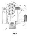
- FIG. 1is a schematic of an exemplary system for practicing the invention
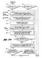
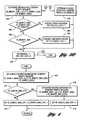
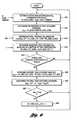
- FIGS. 2-7are flow charts depicting exemplary control methods used by the exemplary system
- FIGS. 8A and 8Bare related plots respectively illustrating a single exemplary trap fill/purge cycle
- FIG. 9is an enlarged view of the portion of the plot of FIG. 8B illustrated within circle 9 thereof;
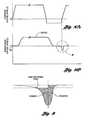
- FIG. 10is a plot illustrating feedgas and tailpipe NO x rates during a trap-filling lean engine operating condition, for both dry and high-relative-humidity conditions.
- FIG. 11is a flow chart depicting an exemplary method for determining the nominal oxygen storage capacity of the trap.
- an exemplary control system 10 for a gasoline-powered internal combustion engine 12 of a motor vehicleincludes an electronic engine controller 14 having a processor (“CPU”); input/output ports; an electronic storage medium containing processor-executable instructions and calibration values, shown as read-only memory (“ROM”) in this particular example; random-access memory (“RAM”); “keep-alive” memory (“KAM”); and a data bus of any suitable configuration.
- the controller 14receives signals from a variety of sensors coupled to the engine 12 and/or the vehicle as described more fully below and, in turn, controls the operation of each of a set of fuel injectors 16 , each of which is positioned to inject fuel into a respective cylinder 18 of the engine 12 in precise quantities as determined by the controller 14 .
- the controller 14similarly controls the individual operation, i.e., timing, of the current directed through each of a set of spark plugs 20 in a known manner.
- the controller 14also controls an electronic throttle 22 that regulates the mass flow of air into the engine 12 .
- An air mass flow sensor 24positioned at the air intake to the engine's intake manifold 26 , provides a signal MAF representing the air mass flow resulting from positioning of the engine's throttle 22 .
- the air flow signal MAF from the air mass flow sensor 24is utilized by the controller 14 to calculate an air mass value AM which is indicative of a mass of air flowing per unit time into the engine's induction system.
- a first oxygen sensor 28 coupled to the engine's exhaust manifolddetects the oxygen content of the exhaust gas generated by the engine 12 and transmits a representative output signal to the controller 14 .
- a plurality of other sensors, indicated generally at 30generate additional signals including an engine speed signal N and an engine load signal LOAD in a known manner, for use by the controller 14 .
- the engine load sensor 30can be of any suitable configuration, including, by way of example only, an intake manifold pressure sensor, an intake air mass sensor, or a throttle position/angle sensor.
- An exhaust system 32receives the exhaust gas generated upon combustion of the air-fuel mixture in each cylinder 18 .
- the exhaust system 32includes a plurality of emissions control devices, specifically, an upstream three-way catalytic converter (“three-way catalyst 34 ”) and a downstream NO x trap 36 .
- the three-way catalyst 34contains a catalyst material that chemically alters the exhaust gas in a known manner.
- the trap 36alternately stores and releases amounts of engine-generated NO x , based upon such factors, for example, as the intake air-fuel ratio, the trap temperature T (as determined by a suitable trap temperature sensor, not shown), the percentage exhaust gas recirculation, the barometric pressure, the relative humidity of ambient air, the instantaneous trap “fullness,” the current extent of “reversible” sulfurization, and trap aging effects (due, for example, to permanent thermal aging, or to the “deep” diffusion of sulfur into the core of the trap material which cannot subsequently be purged).
- a second oxygen sensor 38positioned immediately downstream of the three-way catalyst 34 , provides exhaust gas oxygen content information to the controller 14 in the form of an output signal SIGNAL 0 .
- the second oxygen sensor's output signal SIGNAL 0is useful in optimizing the performance of the three-way catalyst 34 , and in characterizing the trap's NO x -storage ability in a manner to be described further below.
- the exhaust system 32further includes a NO x sensor 40 positioned downstream of the trap 36 .
- the NO x sensor 40generates two output signals, specifically, a first output signal SIGNALl that is representative of the instantaneous oxygen concentration of the exhaust gas exiting the vehicle tailpipe 42 , and a second output signal SIGNAL 2 representative of the instantaneous NO x concentration in the tailpipe exhaust gas, as taught in U.S. Pat. No. 5,953,907. It will be appreciated that any suitable sensor configuration can be used, including the use of discrete tailpipe exhaust gas sensors, to thereby generate the two desired signals SIGNAL 1 and SIGNAL 2 .
- the controller 14selects a suitable engine operating condition or operating mode characterized by combustion of a “near-stoichiometric” air-fuel mixture, i.e., one whose air-fuel ratio is either maintained substantially at, or alternates generally about, the stoichiometric air-fuel ratio; or of an air-fuel mixture that is either “lean” or “rich” of the near-stoichiometric air-fuel mixture.
- a “near-stoichiometric” air-fuel mixturei.e., one whose air-fuel ratio is either maintained substantially at, or alternates generally about, the stoichiometric air-fuel ratio
- an air-fuel mixturethat is either “lean” or “rich” of the near-stoichiometric air-fuel mixture.
- a selection by the controller 14 of “lean burn” engine operationsignified by the setting of a suitable lean-burn request flag LB_RUNNING_FLG to logical one, means that the controller 14 has determined that conditions are suitable for enabling the system's lean-burn feature, whereupon the engine 12 is alternatingly operated with lean and rich air-fuel mixtures for the purpose of improving overall vehicle fuel economy.
- the controller 14bases the selection of a suitable engine operating condition on a variety of factors, which may include determined measures representative of instantaneous or average engine speed/engine load, or of the current state or condition of the trap (e.g., the trap's NO x -storage efficiency, the current NO x “fill” level, the current NO x fill level relative to the trap's current NO x -storage capacity, the trap's temperature T, and/or the trap's current level of sulfurization), or of other operating parameters, including but not limited to a desired torque indicator obtained from an accelerator pedal position sensor, the current vehicle tailpipe NO x emissions (determined, for example, from the second output signal SIGNAL 2 generated by the NO x sensor 40 ), the percent exhaust gas recirculation, the barometric pressure, or the relative humidity of ambient air.
- factorsmay include determined measures representative of instantaneous or average engine speed/engine load, or of the current state or condition of the trap (e.g., the trap's NO x -storage efficiency, the current
- the controller 14after the controller 14 has confirmed at step 210 that the lean-burn feature is not disabled and, at step 212 , that lean-burn operation has otherwise been requested, the controller 14 conditions enablement of the lean-burn feature, upon determining that tailpipe NO x emissions as detected by the NO x sensor 40 do not exceed permissible emissions levels.
- the controller 14determines an accumulated measure TP_NOX_TOT representing the total tailpipe NO x emissions (in grams) since the start of the immediately-prior NO x purge or desulfurization event, based upon the second output signal SIGNAL 2 generated by the NO x sensor 40 and determined air mass value AM (at steps 216 and 218 ).
- the controller 14determines a measure DIST_EFF_CUR representing the effective cumulative distance “currently” traveled by the vehicle, that is, traveled by the vehicle since the controller 14 last initiated a NO x purge event.
- the controller 14While the current effective-distance-traveled measure DIST_EFF_CUR is determined in any suitable manner, in the exemplary system 10 , the controller 14 generates the current effective-distance-traveled measure DIST_EFF_CUR at step 220 by accumulating detected or determined values for instantaneous vehicle speed VS, as may itself be derived, for example, from engine speed N and selected-transmission-gear information.
- the controller 14“clips” the detected or determined vehicle speed at a minimum velocity VS_MIN, for example, typically ranging from perhaps about 0.2 mph to about 0.3 mph (about 0.3 km/hr to about 0.5 km/hr), in order to include the corresponding “effective” distance traveled, for purposes of emissions, when the vehicle is traveling below that speed, or is at a stop.
- the minimum predetermined vehicle speed VS_MINis characterized by a level of NOx emissions that is at least as great as the levels of NOx emissions generated by the engine 12 when idling at stoichiometry.
- the controller 14determines a modified emissions measure NOX_CUR as the total emissions measure TP_NOX_TOT divided by the effective-distance-traveled measure DIST_EFF_CUR.
- the modified emissions measure NOX_CURis favorably expressed in units of “grams per mile.”
- the controller 14determines a measure ACTIVITY representing a current level of vehicle activity (at step 224 of FIG. 2) and modifies a predetermined maximum emissions threshold NOX_MAX_STD (at step 226 ) based on the determined activity measure to thereby obtain a vehicle-activity-modified NO x -per-mile threshold NOX_MAX which seeks to accommodate the impact of such vehicle activity.
- the controller 14While the vehicle activity measure ACTIVITY is determined at step 224 in any suitable manner based upon one or more measures of engine or vehicle output, including but not limited to a determined desired power, vehicle speed VS, engine speed N, engine torque, wheel torque, or wheel power, in the exemplary system 10 , the controller 14 generates the vehicle activity measure ACTIVITY based upon a determination of instantaneous absolute engine power Pe, as follows:
- TQrepresents a detected or determined value for the engine's absolute torque output
- Nrepresents engine speed
- k Iis a predetermined constant representing the system's moment of inertia.
- the controller 14filters the determined values Pe over time, for example, using a high-pass filter G 1 (s), where s is the Laplace operator known to those skilled in the art, to produce a high-pass filtered engine power value HPe.
- G 1 (s)the Laplace operator known to those skilled in the art
- the controller 14determines a current permissible emissions level NOX_MAX as a predetermined function f 5 of the predetermined maximum emissions threshold NOX_MAX_STD based on the determined vehicle activity measure ACTIVITY.
- the current permissible emissions level NOX_MAXtypically varies between a minimum of about 20 percent of the predetermined maximum emissions threshold NOX_MAX_STD for relatively-high vehicle activity levels (e.g., for many transients) to a maximum of about seventy percent of the predetermined maximum emissions threshold NOX_MAX_STD (the latter value providing a “safety factor” ensuring that actual vehicle emissions do not exceed the proscribed government standard NOX_MAX_STD).
- the controller 14determines whether the modified emissions measure NOX_CUR as determined in step 222 exceeds the maximum emissions level NOX_MAX as determined in step 226 . If the modified emissions measure NOX_CUR does not exceed the current maximum emissions level NOX_MAX, the controller 14 remains free to select a lean engine operating condition in accordance with the exemplary system's lean-burn feature.
- the controller 14determines that the “fill” portion of a “complete” lean-burn fill/purge cycle has been completed, and the controller immediately initiates a purge event at step 230 by setting suitable purge event flags PRG_FLG and PRG_START_FLG to logical one.
- the controller 14determines that a purge event has just been commenced, as by checking the current value for the purge-start flag PRG_START 13 FLG, the controller 14 resets the previously determined values TP_NOX_TOT and DIST_EFF_CUR for the total tailpipe NO x and the effective distance traveled and the determined modified emissions measure NOX_CUR, along with other stored values FG_NOX_TOT and FG_NOX_TOT_MOD (to be discussed below), to zero at step 232 .
- the purg-estart flag PRG_START_FLGis similarly reset to logic zero at that time.
- the controller 14further conditions enablement of the lean-burn feature upon a determination of a positive performance impact or “benefit” of such lean-burn operation over a suitable reference operating condition, for example, a near-stoichiometric operating condition at MBT.
- a suitable reference operating conditionfor example, a near-stoichiometric operating condition at MBT.
- the exemplary system 10uses a fuel efficiency measure calculated for such lean-burn operation with reference to engine operation at the near-stoichiometric operating condition and, more specifically, a relative fuel efficiency or “fuel economy benefit” measure.
- Other suitable performance impacts for use with the exemplary system 10include, without limitation, fuel usage, fuel savings per distance traveled by the vehicle, engine efficiency, overall vehicle tailpipe emissions, and vehicle drivability.
- the inventioncontemplates determination of a performance impact of operating the engine 12 and/or the vehicle's powertrain at any first operating mode relative to any second operating mode, and the difference between the first and second operating modes is not intended to be limited to the use of different air-fuel mixtures.
- the inventionis intended to be advantageously used to determine or characterize an impact of any system or operating condition that affects generated torque, such as, for example, comparing stratified lean operation versus homogeneous lean operation, or determining an effect of exhaust gas recirculation (e.g., a fuel benefit can thus be associated with a given EGR setting), or determining the effect of various degrees of retard of a variable cam timing (“VCT”) system, or characterizing the effect of operating charge motion control valves (“CMCV,” an intake-charge swirl approach, for use with both stratified and homogeneous lean engine operation).
- VCTvariable cam timing
- CMCVoperating charge motion control valves
- the controller 14determines the performance impact of lean-burn operation relative to stoichiometric engine operation at MBT by calculating a torque ratio TR defined as the ratio, for a given speed-load condition, of a determined indicated torque output at a selected air-fuel ratio to a determined indicated torque output at stoichiometric operation, as described further below.
- the controller 14determines the torque ratio TR based upon stored values TQ i,j,k for engine torque, mapped as a function of engine speed N, engine load LOAD, and air-fuel ratio LAMBSE.
- the inventioncontemplates use of absolute torque or acceleration information generated, for example, by a suitable torque meter or accelerometer (not shown), with which to directly evaluate the impact of, or to otherwise generate a measure representative of the impact of, the first operating mode relative to the second operating mode.
- a suitable torque meter or accelerometerto generate such absolute torque or acceleration information
- suitable examplesinclude a strain-gage torque meter positioned on the powertrain's output shaft to detect brake torque, and a high-pulse-frequency Hall-effect acceleration sensor positioned on the engine's crankshaft.
- the inventioncontemplates use, in determining the impact of the first operating mode relative to the second operating mode, of the above-described determined measure Pe of absolute instantaneous engine power.
- the torque or power measure for each operating modeis preferably normalized by a detected or determined fuel flow rate.
- the torque or power measureis either corrected (for example, by taking into account the changed engine speed-load conditions) or normalized (for example, by relating the absolute outputs to fuel flow rate, e.g., as represented by fuel pulse width) because such measures are related to engine speed and system moment of inertia.
- the resulting torque or power measurescan advantageously be used as “on-line” measures of a performance impact.
- absolute instantaneous power or normalized absolute instantaneous powercan be integrated to obtain a relative measure of work performed in each operating mode. If the two modes are characterized by a change in engine speed-load points, then the relative work measure is corrected for thermal efficiency, values for which may be conveniently stored in a ROM look-up table.
- the controller 14first determines at step 310 whether the lean-burn feature is enabled.
- the controller 14determines a first value TQ_LB at step 312 representing an indicated torque output for the engine when operating at the selected lean or rich operating condition, based on its selected air-fuel ratio LAMBSE and the degrees DELTA_SPARK of retard from MBT of its selected ignition timing, and further normalized for fuel flow.
- the controller 14determines a second value TQ_STOICH representing an indicated torque output for the engine 12 when operating with a stoichiometric air-fuel ratio at MBT, likewise normalized for fuel flow.
- the controller 14calculates the lean-burn torque ratio TR_LB by dividing the first normalized torque value TQ_LB with the second normalized torque value TQ_STOICH.
- the controller 14determines a value SAVINGS representative of the cumulative fuel savings to be achieved by operating at the selected lean operating condition relative to the reference stoichiometric operating condition, based upon the air mass value AM, the current (lean or rich) lean-burn air-fuel ratio (LAMBSE) and the determined lean-burn torque ratio TR 13 LB, wherein
- SAVINGSSAVINGS+( AM *LAMBSE*14.65*(1 ⁇ TR — LB )).
- the controller 14determines a value DIST_ACT_CUR representative of the actual miles traveled by the vehicle since the start of the last trap purge or desulfurization event. While the “current” actual distance value DIST_ACT_CUR is determined in any suitable manner, in the exemplary system 10 , the controller 14 determines the current actual distance value DIST_ACT_CUR by accumulating detected or determined instantaneous values VS for vehicle speed.
- the controller 14determines the “current” value FE_BENEFIT_CUR for fuel economy benefit only once per “complete” lean-fill/rich-purge cycle, as determined at steps 228 and 230 of FIG. 2 . And, because the purge event's fuel penalty is directly related to the preceding trap “fill,” the current fuel economy benefit value FE_BENEFIT_CUR is preferably determined at the moment that the purge event is deemed to have just been completed. Thus, at step 322 of FIG.
- the controller 14determines whether a purge event has just been completed following a complete trap fill/purge cycle and, if so, determines at step 324 a value FE_BENEFIT_CUR representing current fuel economy benefit of lean-burn operation over the last complete fill/purge cycle.
- current values FE_BENEFIT_CUR for fuel economy benefitare averaged over the first j complete fill/purge cycles immediately following a trap decontaminating event, such as a desulfurization event, in order to obtain a value FE_BENEFIT_MAX_CUR representing the “current” maximum fuel economy benefit which is likely to be achieved with lean-burn operation, given the then-current level of “permanent” trap sulfurization and aging.
- maximum fuel economy benefit averagingis performed by the controller 14 using a conventional low-pass filter at step 410 .
- the current value FE_BENEFIT_MAX_CURis likewise filtered over j desulfurization events at steps 412 , 414 , 416 and 418 .
- the controller 14similarly averages the current values FE_BENFIT_CUR for fuel economy benefit over the last n trap fill/purge cycles to obtain an average value FE_BENEFIT_AVE representing the average fuel economy benefit being achieved by such lean-burn operation and, hence, likely to be achieved with further lean-burn operation.
- the average fuel economy benefit value FE_BENEFIT_AVEis calculated by the controller 14 at step 330 as a rolling average to thereby provide a relatively noise-insensitive “on-line” measure of the fuel economy performance impact provided by such lean engine operation.
- the controller 14determines a value FE_PENALTY at step 334 representing the fuel economy penalty associated with desulfurization. While the fuel economy penalty value FE_PENALTY is determined in any suitable manner, an exemplary method for determining the fuel economy penalty value FE_PENALTY is illustrated in FIG. 5 . Specifically, in step 510 , the controller 14 updates a stored value DIST_ACT_DSX representing the actual distance that the vehicle has traveled since the termination or “end” of the immediately-preceding desulfurization event.
- the controller 14determines whether the desulfurization event running flag DSX_RUNNING_FLG is equal to logical one, thereby indicating that a desulfurization event is in process. While any suitable method is used for desulfurizing the trap 36 , in the exemplary system 10 , the desulfurization event is characterized by operation of some of the engine's cylinders with a lean air-fuel mixture and other of the engine's cylinders 18 with a rich air-fuel mixture, thereby generating exhaust gas with a slightly-rich bias. At the step 514 , the controller 14 then determines the corresponding fuel-normalized torque values TQ_DSX_LEAN and TQ_DSX_RICH, as described above in connection with FIG.
- the controller 14further determines the corresponding fuel-normalized stoichiometric torque value TQ_STOICH and, at step 518 , the corresponding torque ratios TR_DSX_LEAN and TR_DSX_RICH.
- the controller 14then calculates a cumulative fuel economy penalty value at step 520 , as follows:
- PENALTYPENALTY+( AM/ 2*LAMBSE*14.65*(1 ⁇ TR — DSX _LEAN))+( AM/ 2*LAMBSE*14.65*(1 ⁇ TR — DSX _RICH))
- the controller 14sets a fuel economy penalty calculation flag FE_PNLTY_CALC_FLG equal to logical one to thereby ensure that the current desulfurization fuel economy penalty measure FE_PENALTY_CUR is determined immediately upon termination of the on-going desulfurization event.
- the controller 14determines, at steps 512 and 524 of FIG. 5, that a desulfurization event has just been terminated, the controller 14 then determines the current value FE_PENALTY_CUR for the fuel economy penalty associated with the terminated desulfurization event at step 526 , calculated as the cumulative fuel economy penalty value PENALTY divided by the actual distance value DIST_ACT_DSX. In this way, the fuel economy penalty associated with a desulfurization event is spread over the actual distance that the vehicle has traveled since the immediately-prior desulfurization event.
- the controller 14calculates a rolling average value FE_PENALTY of the last m current fuel economy penalty values FE_PENALTY_CUR to thereby provide a relatively-noise-insensitive measure of the fuel economy performance impact of such desulfurization events.
- the average negative performance impact or “penalty” of desulfurizationtypically ranges between about 0.3 percent to about 0.5 percent of the performance gain achieved through lean-burn operation.
- the controller 14resets the fuel economy penalty calculation flag FE_PNLTY_CALC_FLG to zero, along with the previously determined (and summed) actual distance value DIST_ACT_DSX and the current fuel economy penalty value PENALTY, in anticipation for the next desulfurization event.
- the controller 14requests a desulfurization event only if and when such an event is likely to generate a fuel economy benefit in ensuing lean-burn operation. More specifically, at step 336 , the controller 14 determines whether the difference by which the maximum potential fuel economy benefit FE_BENEFIT_MAX exceeds the current fuel economy benefit FE_BENEFIT_CUR is itself greater than the average fuel economy penalty FE_PENALTY associated with desulfurization. If so, the controller 14 requests a desulfurization event by setting a suitable flag SOX_FULL_FLG to logical one.
- SOX_FULL_FLGa suitable flag SOX_FULL_FLG
- the controller 14determines at step 336 that the difference between the maximum fuel economy benefit value FE_BENEFIT_MAX and the average fuel economy value FE_BENEFIT_AVE is not greater than the fuel economy penalty FE_PENALTY associated with a decontamination event, the controller 14 proceeds to step 340 of FIG. 3, wherein the controller 14 determines whether the average fuel economy benefit value FE_BENEFIT_AVE is greater than zero. If the average fuel economy benefit value is less than zero, and with the penalty associated with any needed desulfurization event already having been determined at step 336 as being greater than the likely improvement to be derived from such desulfurization, the controller 14 disables the lean-burn feature at step 344 of FIG. 3 . The controller 14 then resets the fuel savings value SAVINGS and the current actual distance measure DIST_ACT_CUR to zero at step 342 .
- the controller 14schedules a desulfurization event during lean-burn operation when the trap's average efficiency ⁇ ave is deemed to have fallen below a predetermined minimum efficiency ⁇ min . While the average trap efficiency ⁇ ave is determined in any suitable manner, as seen in FIG. 6, the controller 14 periodically estimates the current efficiency ⁇ cur of the trap 36 during a lean engine operating condition which immediately follows a purge event.
- the controller 14estimates a value FG_NOX_CONC representing the NO x concentration in the exhaust gas entering the trap 36 , for example, using stored values for engine feedgas NO x that are mapped as a function of engine speed N and load LOAD for “dry” feedgas and, preferably, modified for average trap temperature T (as by multiplying the stored values by the temperature-based output of a modifier lookup table, not shown).
- the feedgas NO x concentration value FG_NOX_CONCis further modified to reflect the NO x -reducing activity of the three-way catalyst 34 upstream of the trap 36 , and other factors influencing NO x storage, such as trap temperature T, instantaneous trap efficiency ⁇ inst , and estimated trap sulfation levels.
- the controller 14calculates an instantaneous trap efficiency value ⁇ inst as the feedgas NO x concentration value FG_NOX_CONC divided by the tailpipe NO x concentration value TP_NOX_CONC (previously determined at step 216 of FIG. 2 ).
- the controller 14accumulates the product of the feedgas NO x concentration values FG_NOX_CONC times the current air mass values AM to obtain a measure FG_NOX_TOT representing the total amount of feedgas NO x reaching the trap 36 since the start of the immediately-preceding purge event.
- the controller 14determines a modified total feedgas NO x measure FG_NOX_TOT_MOD by modifying the current value FG_NOX_TOT_as a function of trap temperature T.
- the controller 14determines the current trap efficiency measure ⁇ cur as difference between the modified total feedgas NO x measure FG_NOX_TOT_MOD and the total tailpipe NO x measure TP_NOX_TOT (determined at step 218 of FIG. 2 ), divided by the modified total feedgas NO x measure FG_NOX_TOT_MOD.
- the controller 14filters the current trap efficiency measure measure ⁇ cur , for example, by calculating the average trap efficiency measure ⁇ ave as a rolling average of the last k values for the current trap efficiency measure ⁇ cur .
- the controller 14determines whether the average trap efficiency measure ⁇ ave has fallen below a minimum average efficiency threshold ⁇ min . If the average trap efficiency measure ⁇ ave has indeed fallen below the minimum average efficiency threshold ⁇ min , the controller 14 sets both the desulfurization request flag SOX_FULL_FLG to logical one, at step 626 of FIG. 6 .
- the controller 14schedules a purge event when the modified emissions measure NOX_CUR, as determined in step 222 of FIG. 2, exceeds the maximum emissions level NOX_MAX, as determined in step 226 of FIG. 2 .
- the controller 14determines a suitable rich air-fuel ratio as a function of current engine operating conditions, e.g., sensed values for air mass flow rate.
- the determined rich air-fuel ratio for purging the trap 36 of stored NO xtypically ranges from about 0.65 for “low-speed” operating conditions to perhaps 0.75 or more for “high-speed” operating conditions.
- the controller 14maintains the determined air-fuel ratio until a predetermined amount of CO and/or HC has “broken through” the trap 36 , as indicated by the product of the first output signal SIGNAL 1 generated by the NO x sensor 40 and the output signal AM generated by the mass air flow sensor 24 .
- the controller 14determines at step 712 whether the purge event has just begun by checking the status of the purge-start flag PRG_START_FLG. If the purge event has, in fact, just begun, the controller resets certain registers (to be discussed individually below) to zero.
- the controller 14determines a first excess fuel rate value XS_FUEL_RATE_HEGO at step 716 , by which the first output signal SIGNAL 1 is “rich” of a first predetermined, slightly-rich threshold ⁇ ref (the first threshold ⁇ ref being exceeded shortly after a similarly-positioned HEGO sensor would have “switched”).
- the controller 14determines a first excess fuel measure XS_FUEL_ 1 as by summing the product of the first excess fuel rate value XS_FUEL_RATE_HEGO and the current output signal AM generated by the mass air flow sensor 24 (at step 718 ).
- the resulting first excess fuel measure XS_FUEL 1which represents the amount of excess fuel exiting the tailpipe 42 near the end of the purge event, is graphically illustrated as the cross-hatched area REGION I in FIG. 9 .
- the controller 14determines at step 720 that the first excess fuel measure XS_FUEL_ 1 exceeds a predetermined excess fuel threshold XS_FUEL_REF, the trap 36 is deemed to have been substantially “purged” of stored NO x , and the controller 14 discontinues the rich (purging) operating condition at step 722 by resetting the purge flag PRG_FLG to logical zero.
- the controller 14further initializes a post-purge-event excess fuel determination by setting a suitable flag XS_FUEL_ 2 _CALC to logical one.
- controller 14determines that the purge flag PRG_FLG is not equal to logical one and, further, that the post-purge-event excess fuel determination flag XS_FUEL_ 2 _CALC is set to logical one, the controller 14 begins to determine the amount of additional excess fuel already delivered to (and still remaining in) the exhaust system 32 upstream of the trap 36 as of the time that the purge event is discontinued.
- the controller 14starts determining a second excess fuel measure XS_FUEL_ 2 by summing the product of the difference XS_FUEL_RATE_STOICH by which the first output signal SIGNAL 1 is rich of stoichiometry, and summing the product of the difference XS_FUEL_RATE_STOICH and the mass air flow rate AM.
- the controller 14continues to sum the difference XS_FUEL_RATE_STOICH until the first output signal SIGNAL 1 from the NOx sensor 40 indicates a stoichiometric value, at step 730 of FIG.
- the controller 14resets the post-purge-event excess fuel determination flag XS_FUEL_ 2 _CALC at step 732 to logical zero.
- the resulting second excess fuel measure value XS_FUEL_ 2representing the amount of excess fuel exiting the tailpipe 42 after the purge event is discontinued, is graphically illustrated as the cross-hatched area REGION II in FIG. 9 .
- the second excess fuel value XS_FUEL_ 2 in the KAMas a function of engine speed and load, for subsequent use by the controller 14 in optimizing the purge event.
- the exemplary system 10also periodically determines a measure NOX_CAP representing the nominal NO x -storage capacity of the trap 36 .
- the controller 14compares the instantaneous trap efficiency ⁇ inst as determined at step 612 of FIG. 6, to the predetermined reference efficiency value ⁇ ref . While any appropriate reference efficiency value ⁇ ref is used, in the exemplary system 10 , the reference efficiency value ⁇ ref is set to a value significantly greater than the minimum efficiency threshold ⁇ min . By way of example only, in the exemplary system 10 , the reference efficiency value ⁇ ref is set to a value of about 0.65.
- the controller 14When the controller 14 first determines that the instantaneous trap efficiency ⁇ inst has fallen below the reference efficiency value ⁇ ref , the controller 14 immediately initiates a purge event, even though the current value for the modified tailpipe emissions measure NOX_CUR, as determined in step 222 of FIG. 2, likely has not yet exceeded the maximum emissions level NOX_MAX.
- the exemplary system 10automatically adjusts the capacity-determining “short-fill” times t A and t B at which respective dry and relatively-high-humidity engine operation exceed their respective “trigger” concentrations C A and C B .
- the controller 14determines the first excess (purging) fuel value XS_FUEL_ 1 using the closed-loop purge event optimizing process described above.
- the controller 14determines a current NO x -storage capacity measure NOX_CAP_CUR as the difference between the determined first excess (purging) fuel value XS_FUEL_ 1 and a filtered measure O2_CAP representing the nominal oxygen storage capacity of the trap 36 . While the oxygen storage capacity measure O2_CAP is determined by the controller 14 in any suitable manner, in the exemplary system 10 , the oxygen storage capacity measure O2_CAP is determined by the controller 14 immediately after a complete-cycle purge event, as illustrated in FIG. 11 .
- the controller 14determines at step 1110 whether the air-fuel ratio of the exhaust gas air-fuel mixture upstream of the trap 36 , as indicated by the output signal SIGNAL 0 generated by the upstream oxygen sensor 38 , is lean of stoichiometry.
- the controller 14thereafter confirms, at step 1112 , that the air mass value AM, representing the current air charge being inducted into the cylinders 18 , is less than a reference value AMref, thereby indicating a relatively-low space velocity under which certain time delays or lags due, for example, to the exhaust system piping fuel system are de-emphasized.
- the reference air mass value AM refis preferably selected as a relative percentage of the maximum air mass value for the engine 12 , itself typically expressed in terms of maximum air charge at STP.
- the reference air mass value AM refis no greater than about twenty percent of the maximum air charge at STP and, most preferably, is no greater than about fifteen percent of the maximum air charge at STP.
- the controller 14determines whether the downstream exhaust gas is still at stoichiometry, using the first output signal SIGNAL 1 generated by the No x sensor 40 . If so, the trap 36 is still storing oxygen, and the controller 14 accumulates a measure O2_CAP_CUR representing the current oxygen storage capacity of the trap 36 using either the oxygen content signal SIGNAL 0 generated by the upstream oxygen sensor 38 , as illustrated in step 1116 of FIG. 11, or, alternatively, from the injector pulse-width, which provides a measure of the fuel injected into each cylinder 18 , in combination with the current air mass value AM.
- the controller 14sets a suitable flag O2_CALC_FLG to logical one to indicate that an oxygen storage determination is on-going.
- the current oxygen storage capacity measure O2_CAP_CURis accumulated until the downstream oxygen content signal SIGNALl from the NO x sensor 40 goes lean of stoichiometry, thereby indicating that the trap 36 has effectively been saturated with oxygen.
- the upstream oxygen contentgoes to stoichiometry or rich-of-stoichiometry (as determined at step 1110 ), or the current air mass value AM rises above the reference air mass value AM ref (as determined at step 1112 ), before the downstream exhaust gas “goes lean” (as determined at step 1114 )
- the accumulated measure O2_CAP_CUR and the determination flag O2_CALC_FLGare each reset to zero at step 1120 . In this manner, only uninterrupted, relatively-low-space-velocity “oxygen fills” are included in any filtered value for the trap's oxygen storage capacity.
- the controller 14determines, at steps 1114 and 1122 , that the downstream oxygen content has “gone lean” following a suitable relatively-low-space-velocity oxygen fill, i.e., with the capacity determination flag O2_CALC_FLG equal to logical one, at step 1124 , the controller 14 determines the filtered oxygen storage measure O2_CAP using, for example, a rolling average of the last k current values O2_CAP_CUR.
- the purge eventis triggered as a function of the instantaneous trap efficiency measure ⁇ inst , and because the resulting current capacity measure NOX_CAP_CUR is directly related to the amount of purge fuel needed to release the stored NO x from the trap 36 (illustrated as REGIONS III and IV on FIG. 10 corresponding to dry and high-humidity conditions, respectively, less the amount of purge fuel attributed to release of stored oxygen), a relatively repeatable measure NOX_CAP_CUR is obtained which is likewise relatively immune to changes in ambient humidity.
- the controller 14calculates the nominal NO x -storage capacity measure NOX_CAP based upon the last m values for the current capacity measure NOX_CAP_CUR, for example, calculated as a rolling average value.
- the controller 14determines the current trap capacity measure NOX_CAP_CUR based on the difference between accumulated measures representing feedgas and tailpipe NO x at the point in time when the instantaneous trap efficiency ⁇ inst first falls below the reference efficiency threshold ⁇ ref . Specifically, at the moment the instantaneous trap efficiency ⁇ inst first falls below the reference efficiency threshold ⁇ ref , the controller 14 determines the current trap capacity measure NOX_CAP_CUR as the difference between the modified total feedgas NO x measure FG_NOX_TOT_MOD (determined at step 616 of FIG. 6) and the total tailpipe NO x measure TP_NOX_TOT (determined at step 218 of FIG. 2 ).
- the controller 14advantageously need not immediately disable or discontinue lean engine operation when determining the current trap capacity measure NOX_CAP_CUR using the alternative method. It will also be appreciated that the oxygen storage capacity measure O2_CAP, standing alone, is useful in characterizing the overall performance or “ability” of the NO x trap to reduce vehicle emissions.
- the controller 14advantageously evaluates the likely continued vehicle emissions performance during lean engine operation as a function of one of the trap efficiency measures ⁇ inst , ⁇ cur or ⁇ ave , and the vehicle activity measure ACTIVITY. Specifically, if the controller 14 determines that the vehicle's overall emissions performance would be substantively improved by immediately purging the trap 36 of stored NO x , the controller 14 discontinues lean operation and initiates a purge event. In this manner, the controller 14 operates to discontinue a lean engine operating condition, and initiates a purge event, before the modified emissions measure NOX_CUR exceeds the modified emissions threshold NOX_MAX. Similarly, to the extent that the controller 14 has disabled lean engine operation due, for example, to a low trap operating temperature, the controller 14 will delay the scheduling of any purge event until such time as the controller 14 has determined that lean engine operation may be beneficially resumed.
- the exemplary system 10is able to advantageously secure significant fuel economy gains from such lean engine operation without compromising vehicle emissions standards.
Landscapes
- Engineering & Computer Science (AREA)
- Chemical & Material Sciences (AREA)
- Combustion & Propulsion (AREA)
- Mechanical Engineering (AREA)
- General Engineering & Computer Science (AREA)
- Electrical Control Of Air Or Fuel Supplied To Internal-Combustion Engine (AREA)
- Combined Controls Of Internal Combustion Engines (AREA)
Abstract
Description
Claims (40)
Priority Applications (2)
| Application Number | Priority Date | Filing Date | Title |
|---|---|---|---|
| US09/528,217US6708483B1 (en) | 2000-03-17 | 2000-03-17 | Method and apparatus for controlling lean-burn engine based upon predicted performance impact |
| EP01302360AEP1134395A3 (en) | 2000-03-17 | 2001-03-14 | Method and apparatus for controlling lean-burn engine |
Applications Claiming Priority (1)
| Application Number | Priority Date | Filing Date | Title |
|---|---|---|---|
| US09/528,217US6708483B1 (en) | 2000-03-17 | 2000-03-17 | Method and apparatus for controlling lean-burn engine based upon predicted performance impact |
Publications (1)
| Publication Number | Publication Date |
|---|---|
| US6708483B1true US6708483B1 (en) | 2004-03-23 |
Family
ID=24104735
Family Applications (1)
| Application Number | Title | Priority Date | Filing Date |
|---|---|---|---|
| US09/528,217Expired - LifetimeUS6708483B1 (en) | 2000-03-17 | 2000-03-17 | Method and apparatus for controlling lean-burn engine based upon predicted performance impact |
Country Status (2)
| Country | Link |
|---|---|
| US (1) | US6708483B1 (en) |
| EP (1) | EP1134395A3 (en) |
Cited By (5)
| Publication number | Priority date | Publication date | Assignee | Title |
|---|---|---|---|---|
| US20070240407A1 (en)* | 2004-06-08 | 2007-10-18 | Ruth Michael J | Method for modifying trigger level for adsorber regeneration |
| US20080147295A1 (en)* | 2006-12-19 | 2008-06-19 | General Electric Company | System and method for operating a compression-ignition engine |
| US7823561B2 (en)* | 2007-12-17 | 2010-11-02 | Honda Motor Co., Ltd. | Method and apparatus for controlling ignition timing of an internal combustion engine based on engine rotary speed |
| US20120192833A1 (en)* | 2011-02-01 | 2012-08-02 | Mazda Motor Corporation | Internal combustion engine control apparatus |
| US20170021831A1 (en)* | 2015-07-23 | 2017-01-26 | Ford Global Technologies, Llc | Lnt control with adaptive cruise control |
Families Citing this family (2)
| Publication number | Priority date | Publication date | Assignee | Title |
|---|---|---|---|---|
| JP4042388B2 (en)* | 2001-11-12 | 2008-02-06 | トヨタ自動車株式会社 | Exhaust gas purification device for internal combustion engine |
| JP4158733B2 (en) | 2004-03-29 | 2008-10-01 | 株式会社デンソー | Fuel injection device |
Citations (105)
| Publication number | Priority date | Publication date | Assignee | Title |
|---|---|---|---|---|
| US3696618A (en) | 1971-04-19 | 1972-10-10 | Universal Oil Prod Co | Control system for an engine system |
| US3969932A (en) | 1974-09-17 | 1976-07-20 | Robert Bosch G.M.B.H. | Method and apparatus for monitoring the activity of catalytic reactors |
| US4033122A (en) | 1973-11-08 | 1977-07-05 | Nissan Motor Co., Ltd. | Method of and system for controlling air fuel ratios of mixtures into an internal combustion engine |
| US4036014A (en) | 1973-05-30 | 1977-07-19 | Nissan Motor Co., Ltd. | Method of reducing emission of pollutants from multi-cylinder engine |
| US4178883A (en) | 1977-01-25 | 1979-12-18 | Robert Bosch Gmbh | Method and apparatus for fuel/air mixture adjustment |
| US4251989A (en) | 1978-09-08 | 1981-02-24 | Nippondenso Co., Ltd. | Air-fuel ratio control system |
| US4622809A (en) | 1984-04-12 | 1986-11-18 | Daimler-Benz Aktiengesellschaft | Method and apparatus for monitoring and adjusting λ-probe-controlled catalytic exhaust gas emission control systems of internal combustion engines |
| JPS6297630A (en) | 1985-10-24 | 1987-05-07 | Nippon Shokubai Kagaku Kogyo Co Ltd | Method for removing nitrogen oxide from nitrogen oxide-containing gas |
| JPS62117620A (en) | 1985-11-19 | 1987-05-29 | Nippon Shokubai Kagaku Kogyo Co Ltd | Method for removing nitrogen oxide contained in exhaust gas of gasoline engine |
| US4854123A (en) | 1987-01-27 | 1989-08-08 | Nippon Shokubai Kagaku Kogyo Co., Ltd. | Method for removal of nitrogen oxides from exhaust gas of diesel engine |
| US4884066A (en) | 1986-11-20 | 1989-11-28 | Ngk Spark Plug Co., Ltd. | Deterioration detector system for catalyst in use for emission gas purifier |
| EP0351197A2 (en) | 1988-07-13 | 1990-01-17 | Johnson Matthey Public Limited Company | Improvements in pollution control |
| US4913122A (en) | 1987-01-14 | 1990-04-03 | Nissan Motor Company Limited | Air-fuel ratio control system |
| US4964272A (en) | 1987-07-20 | 1990-10-23 | Toyota Jidosha Kabushiki Kaisha | Air-fuel ratio feedback control system including at least downstreamside air-fuel ratio sensor |
| US5009210A (en) | 1986-01-10 | 1991-04-23 | Nissan Motor Co., Ltd. | Air/fuel ratio feedback control system for lean combustion engine |
| EP0444783A1 (en) | 1990-02-13 | 1991-09-04 | Lucas Industries Public Limited Company | Exhaust gas catalyst monitoring |
| US5088281A (en) | 1988-07-20 | 1992-02-18 | Toyota Jidosha Kabushiki Kaisha | Method and apparatus for determining deterioration of three-way catalysts in double air-fuel ratio sensor system |
| US5097700A (en) | 1990-02-27 | 1992-03-24 | Nippondenso Co., Ltd. | Apparatus for judging catalyst of catalytic converter in internal combustion engine |
| EP0503882A1 (en) | 1991-03-13 | 1992-09-16 | Toyota Jidosha Kabushiki Kaisha | Exhaust gas purification system for an internal combustion engine |
| US5165230A (en) | 1990-11-20 | 1992-11-24 | Toyota Jidosha Kabushiki Kaisha | Apparatus for determining deterioration of three-way catalyst of internal combustion engine |
| US5174111A (en) | 1991-01-31 | 1992-12-29 | Toyota Jidosha Kabushiki Kaisha | Exhaust gas purification system for an internal combustion engine |
| US5189876A (en) | 1990-02-09 | 1993-03-02 | Toyota Jidosha Kabushiki Kaisha | Exhaust gas purification system for an internal combustion engine |
| US5201802A (en) | 1991-02-04 | 1993-04-13 | Toyota Jidosha Kabushiki Kaisha | Exhaust gas purification system for an internal combustion engine |
| US5222471A (en) | 1992-09-18 | 1993-06-29 | Kohler Co. | Emission control system for an internal combustion engine |
| US5233830A (en) | 1990-05-28 | 1993-08-10 | Toyota Jidosha Kabushiki Kaisha | Exhaust gas purification system for an internal combustion engine |
| US5267439A (en) | 1990-12-13 | 1993-12-07 | Robert Bosch Gmbh | Method and arrangement for checking the aging condition of a catalyzer |
| US5270024A (en) | 1989-08-31 | 1993-12-14 | Tosoh Corporation | Process for reducing nitrogen oxides from exhaust gas |
| US5272871A (en) | 1991-05-24 | 1993-12-28 | Kabushiki Kaisha Toyota Chuo Kenkyusho | Method and apparatus for reducing nitrogen oxides from internal combustion engine |
| US5325664A (en) | 1991-10-18 | 1994-07-05 | Honda Giken Kogyo Kabushiki Kaisha | System for determining deterioration of catalysts of internal combustion engines |
| US5331809A (en) | 1989-12-06 | 1994-07-26 | Toyota Jidosha Kabushiki Kaisha | Exhaust gas purification system for an internal combustion engine |
| US5335538A (en) | 1991-08-30 | 1994-08-09 | Robert Bosch Gmbh | Method and arrangement for determining the storage capacity of a catalytic converter |
| US5357750A (en) | 1990-04-12 | 1994-10-25 | Ngk Spark Plug Co., Ltd. | Method for detecting deterioration of catalyst and measuring conversion efficiency thereof with an air/fuel ratio sensor |
| US5377484A (en) | 1992-12-09 | 1995-01-03 | Toyota Jidosha Kabushiki Kaisha | Device for detecting deterioration of a catalytic converter for an engine |
| US5402641A (en) | 1992-07-24 | 1995-04-04 | Toyota Jidosha Kabushiki Kaisha | Exhaust gas purification apparatus for an internal combustion engine |
| US5410873A (en) | 1991-06-03 | 1995-05-02 | Isuzu Motors Limited | Apparatus for diminishing nitrogen oxides |
| US5412946A (en) | 1991-10-16 | 1995-05-09 | Toyota Jidosha Kabushiki Kaisha | NOx decreasing apparatus for an internal combustion engine |
| US5412945A (en) | 1991-12-27 | 1995-05-09 | Kabushiki Kaisha Toyota Cho Kenkusho | Exhaust purification device of an internal combustion engine |
| US5414994A (en) | 1994-02-15 | 1995-05-16 | Ford Motor Company | Method and apparatus to limit a midbed temperature of a catalytic converter |
| US5419122A (en) | 1993-10-04 | 1995-05-30 | Ford Motor Company | Detection of catalytic converter operability by light-off time determination |
| US5423181A (en) | 1992-09-02 | 1995-06-13 | Toyota Jidosha Kabushiki Kaisha | Exhaust gas purification device of an engine |
| US5433074A (en) | 1992-07-30 | 1995-07-18 | Toyota Jidosha Kabushiki Kaisha | Exhaust gas purification device for an engine |
| US5437153A (en) | 1992-06-12 | 1995-08-01 | Toyota Jidosha Kabushiki Kaisha | Exhaust purification device of internal combustion engine |
| US5448887A (en) | 1993-05-31 | 1995-09-12 | Toyota Jidosha Kabushiki Kaisha | Exhaust gas purification device for an engine |
| US5450722A (en) | 1992-06-12 | 1995-09-19 | Toyota Jidosha Kabushiki Kaisha | Exhaust purification device of internal combustion engine |
| US5452576A (en) | 1994-08-09 | 1995-09-26 | Ford Motor Company | Air/fuel control with on-board emission measurement |
| US5472673A (en) | 1992-08-04 | 1995-12-05 | Toyota Jidosha Kabushiki Kaisha | Exhaust gas purification device for an engine |
| US5473890A (en) | 1992-12-03 | 1995-12-12 | Toyota Jidosha Kabushiki Kaisha | Exhaust purification device of internal combustion engine |
| US5473887A (en) | 1991-10-03 | 1995-12-12 | Toyota Jidosha Kabushiki Kaisha | Exhaust purification device of internal combustion engine |
| US5483795A (en) | 1993-01-19 | 1996-01-16 | Toyota Jidosha Kabushiki Kaisha | Exhaust purification device of internal combustion engine |
| US5544482A (en) | 1994-03-18 | 1996-08-13 | Honda Giken Kogyo Kabushiki Kaisha | Exhaust gas-purifying system for internal combustion engines |
| US5551231A (en) | 1993-11-25 | 1996-09-03 | Toyota Jidosha Kabushiki Kaisha | Engine exhaust gas purification device |
| US5577382A (en) | 1994-06-30 | 1996-11-26 | Toyota Jidosha Kabushiki Kaisha | Exhaust purification device of internal combustion engine |
| US5595060A (en) | 1994-05-10 | 1997-01-21 | Mitsubishi Jidosha Kogyo Kabushiki Kaisha | Apparatus and method for internal-combustion engine control |
| US5598703A (en) | 1995-11-17 | 1997-02-04 | Ford Motor Company | Air/fuel control system for an internal combustion engine |
| US5622047A (en) | 1992-07-03 | 1997-04-22 | Nippondenso Co., Ltd. | Method and apparatus for detecting saturation gas amount absorbed by catalytic converter |
| US5626117A (en) | 1994-07-08 | 1997-05-06 | Ford Motor Company | Electronic ignition system with modulated cylinder-to-cylinder timing |
| US5626014A (en) | 1995-06-30 | 1997-05-06 | Ford Motor Company | Catalyst monitor based on a thermal power model |
| US5655363A (en) | 1994-11-25 | 1997-08-12 | Honda Giken Kogyo Kabushiki Kaisha | Air-fuel ratio control system for internal combustion engines |
| US5657625A (en) | 1994-06-17 | 1997-08-19 | Mitsubishi Jidosha Kogyo Kabushiki Kaisha | Apparatus and method for internal combustion engine control |
| US5693877A (en) | 1993-06-22 | 1997-12-02 | Hitachi, Ltd. | Evaluating method for NOx eliminating catalyst, an evaluating apparatus therefor, and an efficiency controlling method therefor |
| US5713199A (en) | 1995-03-28 | 1998-02-03 | Toyota Jidosha Kabushiki Kaisha | Device for detecting deterioration of NOx absorbent |
| US5715679A (en) | 1995-03-24 | 1998-02-10 | Toyota Jidosha Kabushiki Kaisha | Exhaust purification device of an engine |
| US5722236A (en) | 1996-12-13 | 1998-03-03 | Ford Global Technologies, Inc. | Adaptive exhaust temperature estimation and control |
| US5724808A (en) | 1995-04-26 | 1998-03-10 | Honda Giken Kogyo Kabushiki Kaisha | Air-fuel ratio control system for internal combustion engines |
| US5732554A (en) | 1995-02-14 | 1998-03-31 | Toyota Jidosha Kabushiki Kaisha | Exhaust gas purification device for an internal combustion engine |
| US5735119A (en) | 1995-03-24 | 1998-04-07 | Toyota Jidosha Kabushiki Kaisha | Exhaust purification device of an engine |
| US5740669A (en) | 1994-11-25 | 1998-04-21 | Toyota Jidosha Kabushiki Kaisha | Exhaust gas purification device for an engine |
| US5743084A (en) | 1996-10-16 | 1998-04-28 | Ford Global Technologies, Inc. | Method for monitoring the performance of a nox trap |
| US5746052A (en) | 1994-09-13 | 1998-05-05 | Toyota Jidosha Kabushiki Kaisha | Exhaust gas purification device for an engine |
| US5746049A (en) | 1996-12-13 | 1998-05-05 | Ford Global Technologies, Inc. | Method and apparatus for estimating and controlling no x trap temperature |
| US5752492A (en) | 1996-06-20 | 1998-05-19 | Toyota Jidosha Kabushiki Kaisha | Apparatus for controlling the air-fuel ratio in an internal combustion engine |
| US5771686A (en) | 1995-11-20 | 1998-06-30 | Mercedes-Benz Ag | Method and apparatus for operating a diesel engine |
| US5771685A (en) | 1996-10-16 | 1998-06-30 | Ford Global Technologies, Inc. | Method for monitoring the performance of a NOx trap |
| US5778666A (en)* | 1996-04-26 | 1998-07-14 | Ford Global Technologies, Inc. | Method and apparatus for improving engine fuel economy |
| US5792436A (en) | 1996-05-13 | 1998-08-11 | Engelhard Corporation | Method for using a regenerable catalyzed trap |
| US5802843A (en) | 1994-02-10 | 1998-09-08 | Hitachi, Ltd. | Method and apparatus for diagnosing engine exhaust gas purification system |
| US5803048A (en) | 1994-04-08 | 1998-09-08 | Honda Giken Kogyo Kabushiki Kaisha | System and method for controlling air-fuel ratio in internal combustion engine |
| US5813387A (en)* | 1991-02-25 | 1998-09-29 | Hitachi, Ltd. | Change gear control device using acceleration and gear ratio as parameters for automatic transmission in a motor vehicle and the method therefor |
| US5832722A (en) | 1997-03-31 | 1998-11-10 | Ford Global Technologies, Inc. | Method and apparatus for maintaining catalyst efficiency of a NOx trap |
| US5842340A (en) | 1997-02-26 | 1998-12-01 | Motorola Inc. | Method for controlling the level of oxygen stored by a catalyst within a catalytic converter |
| US5850735A (en)* | 1995-09-11 | 1998-12-22 | Toyota Jidosha Kabushiki Kaisha | Method for purifying exhaust gas of an internal combustion engine |
| US5865027A (en) | 1995-04-12 | 1999-02-02 | Toyota Jidosha Kabushiki Kaisha | Device for determining the abnormal degree of deterioration of a catalyst |
| US5867983A (en)* | 1995-11-02 | 1999-02-09 | Hitachi, Ltd. | Control system for internal combustion engine with enhancement of purification performance of catalytic converter |
| US5938715A (en) | 1997-04-07 | 1999-08-17 | Siemens Aktiengesellschaft | Method for monitoring the conversion capacity of a catalytic converter |
| US5970707A (en) | 1997-09-19 | 1999-10-26 | Toyota Jidosha Kabushiki Kaisha | Exhaust gas purification device for an internal combustion engine |
| US5974793A (en) | 1996-04-19 | 1999-11-02 | Toyota Jidosha Kabushiki Kaisha | Exhaust gas purification device for an internal combustion engine |
| US5974791A (en) | 1997-03-04 | 1999-11-02 | Toyota Jidosha Kabushiki Kaisha | Exhaust gas purification device for an internal combustion engine |
| US5974788A (en) | 1997-08-29 | 1999-11-02 | Ford Global Technologies, Inc. | Method and apparatus for desulfating a nox trap |
| US5979404A (en)* | 1994-06-17 | 1999-11-09 | Hitachi, Ltd. | Output torque control apparatus and method for an internal combustion engine |
| US5983627A (en) | 1997-09-02 | 1999-11-16 | Ford Global Technologies, Inc. | Closed loop control for desulfating a NOx trap |
| US5992142A (en) | 1996-09-28 | 1999-11-30 | Volkswagen Ag | No exhaust emission control method and arrangement |
| US5996338A (en) | 1996-11-01 | 1999-12-07 | Toyota Jidosha Kabushiki Kaisha | Exhaust gas purifying device for engine |
| US6014859A (en) | 1997-08-25 | 2000-01-18 | Toyota Jidosha Kabushiki Kaisha | Device for purifying exhaust gas of engine |
| US6023929A (en) | 1995-08-26 | 2000-02-15 | Ford Global Technologies, Inc. | Engine with cylinder deactivation |
| US6058700A (en) | 1997-05-26 | 2000-05-09 | Toyota Jidosha Kabushiki Kaisha | Device for purifying exhaust gas of engine |
| US6079204A (en)* | 1998-09-21 | 2000-06-27 | Ford Global Technologies, Inc. | Torque control for direct injected engines using a supplemental torque apparatus |
| US6092021A (en)* | 1997-12-01 | 2000-07-18 | Freightliner Corporation | Fuel use efficiency system for a vehicle for assisting the driver to improve fuel economy |
| US6102019A (en)* | 1999-01-07 | 2000-08-15 | Tjb Engineering, Inc. | Advanced intelligent fuel control system |
| US6105365A (en) | 1997-04-08 | 2000-08-22 | Engelhard Corporation | Apparatus, method, and system for concentrating adsorbable pollutants and abatement thereof |
| JP3135417B2 (en) | 1993-05-26 | 2001-02-13 | 株式会社日立製作所 | Broadcasting system, broadcast transmitting / receiving system and broadcast receiver |
| US6189523B1 (en)* | 1998-04-29 | 2001-02-20 | Anr Pipeline Company | Method and system for controlling an air-to-fuel ratio in a non-stoichiometric power governed gaseous-fueled stationary internal combustion engine |
| US6202407B1 (en) | 1999-04-20 | 2001-03-20 | The Regents Of The University Of California | Nox reduction system utilizing pulsed hydrocarbon injection |
| US6216448B1 (en)* | 1998-01-17 | 2001-04-17 | Robert Bosch Gmbh | Method of diagnosing an NOX storage catalytic converter during operation of an internal combustion engine |
| US6327847B1 (en) | 2000-03-17 | 2001-12-11 | Ford Global Technologies, Inc. | Method for improved performance of a vehicle |
| US6477832B1 (en) | 2000-03-17 | 2002-11-12 | Ford Global Technologies, Inc. | Method for improved performance of a vehicle having an internal combustion engine |
Family Cites Families (3)
| Publication number | Priority date | Publication date | Assignee | Title |
|---|---|---|---|---|
| JPH1071325A (en) | 1996-06-21 | 1998-03-17 | Ngk Insulators Ltd | Method for controlling engine exhaust gas system and method for detecting deterioration in catalyst/ adsorption means |
| DE19705335C1 (en)* | 1997-02-12 | 1998-09-17 | Siemens Ag | Process for the regeneration of a storage catalytic converter |
| FR2792033B1 (en)* | 1999-04-12 | 2001-06-01 | Renault | METHOD AND DEVICE FOR DIAGNOSING THE OPERATING STATE OF A CATALYTIC POT FOR TREATING THE EXHAUST GASES OF AN INTERNAL COMBUSTION ENGINE |
- 2000
- 2000-03-17USUS09/528,217patent/US6708483B1/ennot_activeExpired - Lifetime
- 2001
- 2001-03-14EPEP01302360Apatent/EP1134395A3/ennot_activeWithdrawn
Patent Citations (108)
| Publication number | Priority date | Publication date | Assignee | Title |
|---|---|---|---|---|
| US3696618A (en) | 1971-04-19 | 1972-10-10 | Universal Oil Prod Co | Control system for an engine system |
| US4036014A (en) | 1973-05-30 | 1977-07-19 | Nissan Motor Co., Ltd. | Method of reducing emission of pollutants from multi-cylinder engine |
| US4033122A (en) | 1973-11-08 | 1977-07-05 | Nissan Motor Co., Ltd. | Method of and system for controlling air fuel ratios of mixtures into an internal combustion engine |
| US3969932A (en) | 1974-09-17 | 1976-07-20 | Robert Bosch G.M.B.H. | Method and apparatus for monitoring the activity of catalytic reactors |
| US4178883A (en) | 1977-01-25 | 1979-12-18 | Robert Bosch Gmbh | Method and apparatus for fuel/air mixture adjustment |
| US4251989A (en) | 1978-09-08 | 1981-02-24 | Nippondenso Co., Ltd. | Air-fuel ratio control system |
| US4622809A (en) | 1984-04-12 | 1986-11-18 | Daimler-Benz Aktiengesellschaft | Method and apparatus for monitoring and adjusting λ-probe-controlled catalytic exhaust gas emission control systems of internal combustion engines |
| JPS6297630A (en) | 1985-10-24 | 1987-05-07 | Nippon Shokubai Kagaku Kogyo Co Ltd | Method for removing nitrogen oxide from nitrogen oxide-containing gas |
| JPS62117620A (en) | 1985-11-19 | 1987-05-29 | Nippon Shokubai Kagaku Kogyo Co Ltd | Method for removing nitrogen oxide contained in exhaust gas of gasoline engine |
| US5009210A (en) | 1986-01-10 | 1991-04-23 | Nissan Motor Co., Ltd. | Air/fuel ratio feedback control system for lean combustion engine |
| US4884066A (en) | 1986-11-20 | 1989-11-28 | Ngk Spark Plug Co., Ltd. | Deterioration detector system for catalyst in use for emission gas purifier |
| US4913122A (en) | 1987-01-14 | 1990-04-03 | Nissan Motor Company Limited | Air-fuel ratio control system |
| US4854123A (en) | 1987-01-27 | 1989-08-08 | Nippon Shokubai Kagaku Kogyo Co., Ltd. | Method for removal of nitrogen oxides from exhaust gas of diesel engine |
| US4964272A (en) | 1987-07-20 | 1990-10-23 | Toyota Jidosha Kabushiki Kaisha | Air-fuel ratio feedback control system including at least downstreamside air-fuel ratio sensor |
| EP0351197A2 (en) | 1988-07-13 | 1990-01-17 | Johnson Matthey Public Limited Company | Improvements in pollution control |
| US5088281A (en) | 1988-07-20 | 1992-02-18 | Toyota Jidosha Kabushiki Kaisha | Method and apparatus for determining deterioration of three-way catalysts in double air-fuel ratio sensor system |
| US5270024A (en) | 1989-08-31 | 1993-12-14 | Tosoh Corporation | Process for reducing nitrogen oxides from exhaust gas |
| US5331809A (en) | 1989-12-06 | 1994-07-26 | Toyota Jidosha Kabushiki Kaisha | Exhaust gas purification system for an internal combustion engine |
| US5189876A (en) | 1990-02-09 | 1993-03-02 | Toyota Jidosha Kabushiki Kaisha | Exhaust gas purification system for an internal combustion engine |
| EP0444783A1 (en) | 1990-02-13 | 1991-09-04 | Lucas Industries Public Limited Company | Exhaust gas catalyst monitoring |
| US5097700A (en) | 1990-02-27 | 1992-03-24 | Nippondenso Co., Ltd. | Apparatus for judging catalyst of catalytic converter in internal combustion engine |
| US5357750A (en) | 1990-04-12 | 1994-10-25 | Ngk Spark Plug Co., Ltd. | Method for detecting deterioration of catalyst and measuring conversion efficiency thereof with an air/fuel ratio sensor |
| US5233830A (en) | 1990-05-28 | 1993-08-10 | Toyota Jidosha Kabushiki Kaisha | Exhaust gas purification system for an internal combustion engine |
| US5165230A (en) | 1990-11-20 | 1992-11-24 | Toyota Jidosha Kabushiki Kaisha | Apparatus for determining deterioration of three-way catalyst of internal combustion engine |
| US5267439A (en) | 1990-12-13 | 1993-12-07 | Robert Bosch Gmbh | Method and arrangement for checking the aging condition of a catalyzer |
| US5174111A (en) | 1991-01-31 | 1992-12-29 | Toyota Jidosha Kabushiki Kaisha | Exhaust gas purification system for an internal combustion engine |
| US5201802A (en) | 1991-02-04 | 1993-04-13 | Toyota Jidosha Kabushiki Kaisha | Exhaust gas purification system for an internal combustion engine |
| US5813387A (en)* | 1991-02-25 | 1998-09-29 | Hitachi, Ltd. | Change gear control device using acceleration and gear ratio as parameters for automatic transmission in a motor vehicle and the method therefor |
| US5209061A (en) | 1991-03-13 | 1993-05-11 | Toyota Jidosha Kabushiki Kaisha | Exhaust gas purification system for an internal combustion engine |
| EP0503882A1 (en) | 1991-03-13 | 1992-09-16 | Toyota Jidosha Kabushiki Kaisha | Exhaust gas purification system for an internal combustion engine |
| US5272871A (en) | 1991-05-24 | 1993-12-28 | Kabushiki Kaisha Toyota Chuo Kenkyusho | Method and apparatus for reducing nitrogen oxides from internal combustion engine |
| US5410873A (en) | 1991-06-03 | 1995-05-02 | Isuzu Motors Limited | Apparatus for diminishing nitrogen oxides |
| US5335538A (en) | 1991-08-30 | 1994-08-09 | Robert Bosch Gmbh | Method and arrangement for determining the storage capacity of a catalytic converter |
| US5473887A (en) | 1991-10-03 | 1995-12-12 | Toyota Jidosha Kabushiki Kaisha | Exhaust purification device of internal combustion engine |
| US5412946A (en) | 1991-10-16 | 1995-05-09 | Toyota Jidosha Kabushiki Kaisha | NOx decreasing apparatus for an internal combustion engine |
| US5325664A (en) | 1991-10-18 | 1994-07-05 | Honda Giken Kogyo Kabushiki Kaisha | System for determining deterioration of catalysts of internal combustion engines |
| US5412945A (en) | 1991-12-27 | 1995-05-09 | Kabushiki Kaisha Toyota Cho Kenkusho | Exhaust purification device of an internal combustion engine |
| US5450722A (en) | 1992-06-12 | 1995-09-19 | Toyota Jidosha Kabushiki Kaisha | Exhaust purification device of internal combustion engine |
| US5437153A (en) | 1992-06-12 | 1995-08-01 | Toyota Jidosha Kabushiki Kaisha | Exhaust purification device of internal combustion engine |
| US5622047A (en) | 1992-07-03 | 1997-04-22 | Nippondenso Co., Ltd. | Method and apparatus for detecting saturation gas amount absorbed by catalytic converter |
| US5402641A (en) | 1992-07-24 | 1995-04-04 | Toyota Jidosha Kabushiki Kaisha | Exhaust gas purification apparatus for an internal combustion engine |
| EP0580389B1 (en) | 1992-07-24 | 1995-09-20 | Toyota Jidosha Kabushiki Kaisha | Exhaust gas purification apparatus for an internal combustion engine |
| US5433074A (en) | 1992-07-30 | 1995-07-18 | Toyota Jidosha Kabushiki Kaisha | Exhaust gas purification device for an engine |
| US5472673A (en) | 1992-08-04 | 1995-12-05 | Toyota Jidosha Kabushiki Kaisha | Exhaust gas purification device for an engine |
| US5423181A (en) | 1992-09-02 | 1995-06-13 | Toyota Jidosha Kabushiki Kaisha | Exhaust gas purification device of an engine |
| US5222471A (en) | 1992-09-18 | 1993-06-29 | Kohler Co. | Emission control system for an internal combustion engine |
| US5473890A (en) | 1992-12-03 | 1995-12-12 | Toyota Jidosha Kabushiki Kaisha | Exhaust purification device of internal combustion engine |
| US5377484A (en) | 1992-12-09 | 1995-01-03 | Toyota Jidosha Kabushiki Kaisha | Device for detecting deterioration of a catalytic converter for an engine |
| US5483795A (en) | 1993-01-19 | 1996-01-16 | Toyota Jidosha Kabushiki Kaisha | Exhaust purification device of internal combustion engine |
| JP3135417B2 (en) | 1993-05-26 | 2001-02-13 | 株式会社日立製作所 | Broadcasting system, broadcast transmitting / receiving system and broadcast receiver |
| US5448887A (en) | 1993-05-31 | 1995-09-12 | Toyota Jidosha Kabushiki Kaisha | Exhaust gas purification device for an engine |
| US5693877A (en) | 1993-06-22 | 1997-12-02 | Hitachi, Ltd. | Evaluating method for NOx eliminating catalyst, an evaluating apparatus therefor, and an efficiency controlling method therefor |
| US5419122A (en) | 1993-10-04 | 1995-05-30 | Ford Motor Company | Detection of catalytic converter operability by light-off time determination |
| US5551231A (en) | 1993-11-25 | 1996-09-03 | Toyota Jidosha Kabushiki Kaisha | Engine exhaust gas purification device |
| US5802843A (en) | 1994-02-10 | 1998-09-08 | Hitachi, Ltd. | Method and apparatus for diagnosing engine exhaust gas purification system |
| US5414994A (en) | 1994-02-15 | 1995-05-16 | Ford Motor Company | Method and apparatus to limit a midbed temperature of a catalytic converter |
| US5544482A (en) | 1994-03-18 | 1996-08-13 | Honda Giken Kogyo Kabushiki Kaisha | Exhaust gas-purifying system for internal combustion engines |
| US6012428A (en) | 1994-04-08 | 2000-01-11 | Honda Giken Kogyo Kabushiki Kaisha | Method for controlling air-fuel ratio in internal combustion engine |
| US5803048A (en) | 1994-04-08 | 1998-09-08 | Honda Giken Kogyo Kabushiki Kaisha | System and method for controlling air-fuel ratio in internal combustion engine |
| US5595060A (en) | 1994-05-10 | 1997-01-21 | Mitsubishi Jidosha Kogyo Kabushiki Kaisha | Apparatus and method for internal-combustion engine control |
| US5979404A (en)* | 1994-06-17 | 1999-11-09 | Hitachi, Ltd. | Output torque control apparatus and method for an internal combustion engine |
| US5657625A (en) | 1994-06-17 | 1997-08-19 | Mitsubishi Jidosha Kogyo Kabushiki Kaisha | Apparatus and method for internal combustion engine control |
| US5577382A (en) | 1994-06-30 | 1996-11-26 | Toyota Jidosha Kabushiki Kaisha | Exhaust purification device of internal combustion engine |
| US5626117A (en) | 1994-07-08 | 1997-05-06 | Ford Motor Company | Electronic ignition system with modulated cylinder-to-cylinder timing |
| US5452576A (en) | 1994-08-09 | 1995-09-26 | Ford Motor Company | Air/fuel control with on-board emission measurement |
| US5746052A (en) | 1994-09-13 | 1998-05-05 | Toyota Jidosha Kabushiki Kaisha | Exhaust gas purification device for an engine |
| US5655363A (en) | 1994-11-25 | 1997-08-12 | Honda Giken Kogyo Kabushiki Kaisha | Air-fuel ratio control system for internal combustion engines |
| US5740669A (en) | 1994-11-25 | 1998-04-21 | Toyota Jidosha Kabushiki Kaisha | Exhaust gas purification device for an engine |
| US5732554A (en) | 1995-02-14 | 1998-03-31 | Toyota Jidosha Kabushiki Kaisha | Exhaust gas purification device for an internal combustion engine |
| US5735119A (en) | 1995-03-24 | 1998-04-07 | Toyota Jidosha Kabushiki Kaisha | Exhaust purification device of an engine |
| US5715679A (en) | 1995-03-24 | 1998-02-10 | Toyota Jidosha Kabushiki Kaisha | Exhaust purification device of an engine |
| US5713199A (en) | 1995-03-28 | 1998-02-03 | Toyota Jidosha Kabushiki Kaisha | Device for detecting deterioration of NOx absorbent |
| US5865027A (en) | 1995-04-12 | 1999-02-02 | Toyota Jidosha Kabushiki Kaisha | Device for determining the abnormal degree of deterioration of a catalyst |
| US5724808A (en) | 1995-04-26 | 1998-03-10 | Honda Giken Kogyo Kabushiki Kaisha | Air-fuel ratio control system for internal combustion engines |
| US5626014A (en) | 1995-06-30 | 1997-05-06 | Ford Motor Company | Catalyst monitor based on a thermal power model |
| US6023929A (en) | 1995-08-26 | 2000-02-15 | Ford Global Technologies, Inc. | Engine with cylinder deactivation |
| US5850735A (en)* | 1995-09-11 | 1998-12-22 | Toyota Jidosha Kabushiki Kaisha | Method for purifying exhaust gas of an internal combustion engine |
| US5867983A (en)* | 1995-11-02 | 1999-02-09 | Hitachi, Ltd. | Control system for internal combustion engine with enhancement of purification performance of catalytic converter |
| US5598703A (en) | 1995-11-17 | 1997-02-04 | Ford Motor Company | Air/fuel control system for an internal combustion engine |
| US5771686A (en) | 1995-11-20 | 1998-06-30 | Mercedes-Benz Ag | Method and apparatus for operating a diesel engine |
| US5974793A (en) | 1996-04-19 | 1999-11-02 | Toyota Jidosha Kabushiki Kaisha | Exhaust gas purification device for an internal combustion engine |
| US5778666A (en)* | 1996-04-26 | 1998-07-14 | Ford Global Technologies, Inc. | Method and apparatus for improving engine fuel economy |
| US5792436A (en) | 1996-05-13 | 1998-08-11 | Engelhard Corporation | Method for using a regenerable catalyzed trap |
| US5752492A (en) | 1996-06-20 | 1998-05-19 | Toyota Jidosha Kabushiki Kaisha | Apparatus for controlling the air-fuel ratio in an internal combustion engine |
| US5992142A (en) | 1996-09-28 | 1999-11-30 | Volkswagen Ag | No exhaust emission control method and arrangement |
| US5771685A (en) | 1996-10-16 | 1998-06-30 | Ford Global Technologies, Inc. | Method for monitoring the performance of a NOx trap |
| US5743084A (en) | 1996-10-16 | 1998-04-28 | Ford Global Technologies, Inc. | Method for monitoring the performance of a nox trap |
| US5996338A (en) | 1996-11-01 | 1999-12-07 | Toyota Jidosha Kabushiki Kaisha | Exhaust gas purifying device for engine |
| US5746049A (en) | 1996-12-13 | 1998-05-05 | Ford Global Technologies, Inc. | Method and apparatus for estimating and controlling no x trap temperature |
| US5722236A (en) | 1996-12-13 | 1998-03-03 | Ford Global Technologies, Inc. | Adaptive exhaust temperature estimation and control |
| US5842340A (en) | 1997-02-26 | 1998-12-01 | Motorola Inc. | Method for controlling the level of oxygen stored by a catalyst within a catalytic converter |
| US5974791A (en) | 1997-03-04 | 1999-11-02 | Toyota Jidosha Kabushiki Kaisha | Exhaust gas purification device for an internal combustion engine |
| US5832722A (en) | 1997-03-31 | 1998-11-10 | Ford Global Technologies, Inc. | Method and apparatus for maintaining catalyst efficiency of a NOx trap |
| US5938715A (en) | 1997-04-07 | 1999-08-17 | Siemens Aktiengesellschaft | Method for monitoring the conversion capacity of a catalytic converter |
| US6105365A (en) | 1997-04-08 | 2000-08-22 | Engelhard Corporation | Apparatus, method, and system for concentrating adsorbable pollutants and abatement thereof |
| US6058700A (en) | 1997-05-26 | 2000-05-09 | Toyota Jidosha Kabushiki Kaisha | Device for purifying exhaust gas of engine |
| US6014859A (en) | 1997-08-25 | 2000-01-18 | Toyota Jidosha Kabushiki Kaisha | Device for purifying exhaust gas of engine |
| US5974788A (en) | 1997-08-29 | 1999-11-02 | Ford Global Technologies, Inc. | Method and apparatus for desulfating a nox trap |
| US5983627A (en) | 1997-09-02 | 1999-11-16 | Ford Global Technologies, Inc. | Closed loop control for desulfating a NOx trap |
| US5970707A (en) | 1997-09-19 | 1999-10-26 | Toyota Jidosha Kabushiki Kaisha | Exhaust gas purification device for an internal combustion engine |
| US6092021A (en)* | 1997-12-01 | 2000-07-18 | Freightliner Corporation | Fuel use efficiency system for a vehicle for assisting the driver to improve fuel economy |
| US6216448B1 (en)* | 1998-01-17 | 2001-04-17 | Robert Bosch Gmbh | Method of diagnosing an NOX storage catalytic converter during operation of an internal combustion engine |
| US6189523B1 (en)* | 1998-04-29 | 2001-02-20 | Anr Pipeline Company | Method and system for controlling an air-to-fuel ratio in a non-stoichiometric power governed gaseous-fueled stationary internal combustion engine |
| US6079204A (en)* | 1998-09-21 | 2000-06-27 | Ford Global Technologies, Inc. | Torque control for direct injected engines using a supplemental torque apparatus |
| US6102019A (en)* | 1999-01-07 | 2000-08-15 | Tjb Engineering, Inc. | Advanced intelligent fuel control system |
| US6202407B1 (en) | 1999-04-20 | 2001-03-20 | The Regents Of The University Of California | Nox reduction system utilizing pulsed hydrocarbon injection |
| US6327847B1 (en) | 2000-03-17 | 2001-12-11 | Ford Global Technologies, Inc. | Method for improved performance of a vehicle |
| US6477832B1 (en) | 2000-03-17 | 2002-11-12 | Ford Global Technologies, Inc. | Method for improved performance of a vehicle having an internal combustion engine |
Non-Patent Citations (8)
Cited By (9)
| Publication number | Priority date | Publication date | Assignee | Title |
|---|---|---|---|---|
| US20070240407A1 (en)* | 2004-06-08 | 2007-10-18 | Ruth Michael J | Method for modifying trigger level for adsorber regeneration |
| US7721535B2 (en)* | 2004-06-08 | 2010-05-25 | Cummins Inc. | Method for modifying trigger level for adsorber regeneration |
| US20080147295A1 (en)* | 2006-12-19 | 2008-06-19 | General Electric Company | System and method for operating a compression-ignition engine |
| US8103429B2 (en)* | 2006-12-19 | 2012-01-24 | General Electric Company | System and method for operating a compression-ignition engine |
| US7823561B2 (en)* | 2007-12-17 | 2010-11-02 | Honda Motor Co., Ltd. | Method and apparatus for controlling ignition timing of an internal combustion engine based on engine rotary speed |
| US20120192833A1 (en)* | 2011-02-01 | 2012-08-02 | Mazda Motor Corporation | Internal combustion engine control apparatus |
| US10197036B2 (en)* | 2011-02-01 | 2019-02-05 | Mitsubishi Electric Corporation | Internal combustion engine control apparatus |
| US20170021831A1 (en)* | 2015-07-23 | 2017-01-26 | Ford Global Technologies, Llc | Lnt control with adaptive cruise control |
| US10040454B2 (en)* | 2015-07-23 | 2018-08-07 | Ford Global Technologies, Llc | LNT control with adaptive cruise control |
Also Published As
| Publication number | Publication date |
|---|---|
| EP1134395A2 (en) | 2001-09-19 |
| EP1134395A3 (en) | 2005-03-02 |
Similar Documents
| Publication | Publication Date | Title |
|---|---|---|
| US6594989B1 (en) | Method and apparatus for enhancing fuel economy of a lean burn internal combustion engine | |
| US6438944B1 (en) | Method and apparatus for optimizing purge fuel for purging emissions control device | |
| US6860100B1 (en) | Degradation detection method for an engine having a NOx sensor | |
| US6487849B1 (en) | Method and apparatus for controlling lean-burn engine based upon predicted performance impact and trap efficiency | |
| US6490856B2 (en) | Control for improved vehicle performance | |
| US6499293B1 (en) | Method and system for reducing NOx tailpipe emissions of a lean-burn internal combustion engine | |
| US6810659B1 (en) | Method for determining emission control system operability | |
| US6308515B1 (en) | Method and apparatus for accessing ability of lean NOx trap to store exhaust gas constituent | |
| US6374597B1 (en) | Method and apparatus for accessing ability of lean NOx trap to store exhaust gas constituent | |
| US6629453B1 (en) | Method and apparatus for measuring the performance of an emissions control device | |
| EP1191196B1 (en) | NOx trap capacity | |
| EP1134401B1 (en) | Method for improved performance of a vehicle having an internal combustion engine | |
| US6360530B1 (en) | Method and apparatus for measuring lean-burn engine emissions | |
| US6487850B1 (en) | Method for improved engine control | |
| US6308697B1 (en) | Method for improved air-fuel ratio control in engines | |
| US6708483B1 (en) | Method and apparatus for controlling lean-burn engine based upon predicted performance impact | |
| US6434930B1 (en) | Method and apparatus for controlling lean operation of an internal combustion engine | |
| JP3806399B2 (en) | Exhaust gas purification device for internal combustion engine | |
| US6843051B1 (en) | Method and apparatus for controlling lean-burn engine to purge trap of stored NOx | |
| US6539704B1 (en) | Method for improved vehicle performance | |
| EP1134370B1 (en) | Method and apparatus for enabling lean engine operation upon engine start-up |
Legal Events
| Date | Code | Title | Description |
|---|---|---|---|
| AS | Assignment | Owner name:FORD MOTOR COMPANY, A CORP. OF DELAWARE, MICHIGAN Free format text:ASSIGNMENT OF ASSIGNORS INTEREST;ASSIGNORS:ROBICHAUX, JERRY D.;BIDNER, DAVID KARL;SURNILLA, GOPICHANDRA;REEL/FRAME:010683/0837;SIGNING DATES FROM 20000308 TO 20000313 Owner name:FORD GLOBAL TECHNOLOGIES, INC., A MICHIGAN CORPORA Free format text:ASSIGNMENT OF ASSIGNORS INTEREST;ASSIGNOR:FORD MOTOR COMPANY, A DELAWARE CORPORATION;REEL/FRAME:010681/0624 Effective date:20000313 | |
| AS | Assignment | Owner name:FORD GLOBAL TECHNOLOGIES, LLC, MICHIGAN Free format text:MERGER;ASSIGNOR:FORD GLOBAL TECHNOLOGIES, INC.;REEL/FRAME:013987/0838 Effective date:20030301 Owner name:FORD GLOBAL TECHNOLOGIES, LLC,MICHIGAN Free format text:MERGER;ASSIGNOR:FORD GLOBAL TECHNOLOGIES, INC.;REEL/FRAME:013987/0838 Effective date:20030301 | |
| STCF | Information on status: patent grant | Free format text:PATENTED CASE | |
| FPAY | Fee payment | Year of fee payment:4 | |
| FPAY | Fee payment | Year of fee payment:8 | |
| FPAY | Fee payment | Year of fee payment:12 |