US6708321B2 - Generating a function within a logic design using a dialog box - Google Patents
Generating a function within a logic design using a dialog boxDownload PDFInfo
- Publication number
- US6708321B2 US6708321B2US10/038,706US3870602AUS6708321B2US 6708321 B2US6708321 B2US 6708321B2US 3870602 AUS3870602 AUS 3870602AUS 6708321 B2US6708321 B2US 6708321B2
- Authority
- US
- United States
- Prior art keywords
- function
- operands
- operator
- dialog box
- article
- Prior art date
- Legal status (The legal status is an assumption and is not a legal conclusion. Google has not performed a legal analysis and makes no representation as to the accuracy of the status listed.)
- Expired - Fee Related, expires
Links
Images


Classifications
- G—PHYSICS
- G06—COMPUTING OR CALCULATING; COUNTING
- G06F—ELECTRIC DIGITAL DATA PROCESSING
- G06F30/00—Computer-aided design [CAD]
- G06F30/30—Circuit design
- G06F30/32—Circuit design at the digital level
- G06F30/33—Design verification, e.g. functional simulation or model checking
- G06F30/3308—Design verification, e.g. functional simulation or model checking using simulation
- G—PHYSICS
- G06—COMPUTING OR CALCULATING; COUNTING
- G06F—ELECTRIC DIGITAL DATA PROCESSING
- G06F30/00—Computer-aided design [CAD]
- G06F30/30—Circuit design
- G—PHYSICS
- G06—COMPUTING OR CALCULATING; COUNTING
- G06F—ELECTRIC DIGITAL DATA PROCESSING
- G06F30/00—Computer-aided design [CAD]
- G06F30/30—Circuit design
- G06F30/32—Circuit design at the digital level
- G06F30/33—Design verification, e.g. functional simulation or model checking
Definitions
- This inventionrelates to circuit simulation.
- Logic designs for circuitstypically include either schematic design or text design.
- a schematic designshows a circuit design with logic elements as a two-dimensional diagram.
- Logic elementsare either state elements (e.g., flip-flops, latches, etc.) or combinatorial elements (e.g., AND gates, NOR gates, etc.). State elements provide storage from one cycle of operation to the next cycle of operation. Combinatorial elements are used to perform operations on two or more signals.
- a textual representationdescribes the logic elements of a circuit using one-dimensional text lines.
- Textual representationsare used in hardware description languages (HDLs) which allow designers to simulate logic designs prior to forming the logic on silicon. Examples of such languages include Verilog and Very High-Level Design Language (VHDL). Using these languages, a designer can write code to simulate a logic design and execute the code in order to determine if the logic design performs properly.
- HDLshardware description languages
- VHDLVery High-Level Design Language
- Standard computer languagesmay also be used to simulate a logic design.
- One example of a standard computer language that may be usedis C++.
- FIG. 1is a flowchart showing a process for generating a logic design using programmable binary operators.
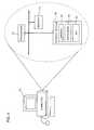
- FIG. 2is a screenshot of a dialog box for generating a logic design having a binary operator.
- FIG. 3is a schematic representation of a function generated from the dialog box in FIG. 2 .
- FIG. 4is a block diagram of a computer system on which the process of FIG. 1 may be performed.
- a process 10is used in generating a logic design to generate a configurable binary operator gate by using programmable binary operators.
- the configurable binary operator gateis a generalized gate structure designed to model a user-defined function comprised of a binary operator acting on two operands.
- the gate structurecan be designed to be an adder, a shifter, a comparator, an incrementor, etc.
- Process 10may be implemented using a computer program running on a computer 50 (FIG. 4) or other type of machine, as described in more detail below.
- a computer programrunning on a computer 50 (FIG. 4) or other type of machine, as described in more detail below.
- binary operatorscomplex logic models can be presented to a user (not shown) that have a simple readable body element comprised of the gate structure and a software code representing the gate structure displayed within the gate structure.
- process 10accesses and displays ( 12 ) a dialog box 22 in response to a user input.
- the usermay use any input/output (I/O) device to access and display ( 12 ) dialog box 22 .
- I/Oinput/output
- design tools employing process 10may reside on a personal computer and the tools may operate in a MS-Windows® environment. If the user determines that a function having a binary operator is needed in the design, the user pulls-down a menu (not shown) or right-clicks a mouse button to access dialog box 22 . In response, process 10 displays dialog box 22 is displayed on a computer monitor.
- dialog box 22may be a graphical user interface (GUI) into which the user inputs data to generate a gate structure (see, e.g., FIG. 3 described below).
- GUIgraphical user interface
- the usermay choose either a signal input or a constant input for a left operand 24 and for a right operand 28 by clicking on a circle 25 next to the desired choice.
- dialog box 22is highlighted indicating to the user a constant has been chosen.
- the usertypes-in a left pin name 26 , a right pin name 30 , and an output pin name 36 .
- the userfurther accesses a pull-down menu 32 to choose a desired binary operator.
- “OK” button 34the user has provided the inputs from dialog box 22 to process 10 .
- Binary operator symbolscan be a logical operator or a non-logical operator.
- Logical operatorsproduce an output of either a ‘1’ or a ‘0’ or a bit width of 1. For non-logical operators (e.g., “+”, “>>”, etc.), the bit width of the output is equal to the bit width of each input. For example, if the function, a+b, is chosen and an input signal a is 4 bits wide and input signal b is a 4 bits wide, then the resulting output signal is 4 bits wide.
- process 10displays ( 18 ) the function selected as a gate 40 using a Verilog code 42 .
- process 10embeds a textual combinatorial data block into a two-dimensional schematic presentation.
- input signal ais represented by “opA[3:0]”
- input signal bis represented by “opB[3:0].”
- input signal a and input signal bare each 4 bits wide.
- Process 10automatically (i.e., without user intervention) generates an output signal “out” represented as “opOut[0:0],” as a one bit wide signal.
- process 10reduces the need to have large libraries based on bit-width size by automatically calculating an appropriate bit-width size.
- FIG. 4shows computer 50 for generating a logic design using process 10 .
- Computer 50includes a processor 52 , a memory 54 , and a storage medium 56 (e.g., a hard disk).
- Storage medium 56stores data 62 which defines a logic design, a graphics library 60 used in implementing the logic design, and machine-executable instructions 58 , which are executed by processor 52 out of memory 54 to perform process 10 on data 62 .
- Process 10is not limited to use with the hardware and software of FIG. 4; it may find applicability in any computing or processing environment.
- Process 10may be implemented in hardware, software, or a combination of the two.
- Process 10may be implemented in computer programs executing on programmable computers or other machines that each includes a processor, a storage medium readable by the processor (including volatile and non-volatile memory and/or storage elements), at least one input device, and one or more output devices.
- Program codemay be applied to data entered using an input device, such as a mouse or a keyboard, to perform process 10 and to generate a simulation.
- Each such programmay be implemented in a high level procedural or object-oriented programming language to communicate with a computer system.
- the programscan be implemented in assembly or machine language.
- the languagemay be a compiled or an interpreted language.
- Each computer programmay be stored on an article of manufacture, such as a storage medium or device (e.g., CD-ROM, hard disk, or magnetic diskette), that is readable by a general or special purpose programmable machine for configuring and operating the machine when the storage medium or device is read by the machine to perform process 10 .
- a storage medium or devicee.g., CD-ROM, hard disk, or magnetic diskette
- Process 10may also be implemented as a machine-readable storage medium, configured with a computer program, where, upon execution, instructions in the computer program cause the machine to operate in accordance with process 10 .
- Process 10is not limited to using two operands.
- Process 10can be used with k operands, where k>1.
- Process 10is not limited to binary operators but may be any x-state operators, where x ⁇ 2.
- process 10is not limited to embedding one-dimensional design into a two-dimensional design.
- Processcan be any n-dimensional design embedded into a (n+m)-dimensional design, where n ⁇ 1 and m ⁇ 1.
- Process 10is not limited to the computer languages set forth above, e.g., Verilog, C++, and VHDL. It may be implemented using any appropriate computer language.
- Process 10is also not limited to the order set forth in FIG. 1 . That is, the blocks of process 10 may be executed in a different order than that shown to produce an acceptable result.
Landscapes
- Engineering & Computer Science (AREA)
- Computer Hardware Design (AREA)
- Physics & Mathematics (AREA)
- Theoretical Computer Science (AREA)
- Evolutionary Computation (AREA)
- Geometry (AREA)
- General Engineering & Computer Science (AREA)
- General Physics & Mathematics (AREA)
- Design And Manufacture Of Integrated Circuits (AREA)
Abstract
Description
This application claims priority from U.S. Provisional Application No. 60/315,852, filed Aug. 29, 2001, and titled “Visual Modeling and Design Capture Environment,” which is incorporated by reference.
This invention relates to circuit simulation.
Logic designs for circuits typically include either schematic design or text design. A schematic design shows a circuit design with logic elements as a two-dimensional diagram. Logic elements are either state elements (e.g., flip-flops, latches, etc.) or combinatorial elements (e.g., AND gates, NOR gates, etc.). State elements provide storage from one cycle of operation to the next cycle of operation. Combinatorial elements are used to perform operations on two or more signals.
A textual representation describes the logic elements of a circuit using one-dimensional text lines. Textual representations are used in hardware description languages (HDLs) which allow designers to simulate logic designs prior to forming the logic on silicon. Examples of such languages include Verilog and Very High-Level Design Language (VHDL). Using these languages, a designer can write code to simulate a logic design and execute the code in order to determine if the logic design performs properly.
Standard computer languages may also be used to simulate a logic design. One example of a standard computer language that may be used is C++.
FIG. 1 is a flowchart showing a process for generating a logic design using programmable binary operators.
FIG. 2 is a screenshot of a dialog box for generating a logic design having a binary operator.
FIG. 3 is a schematic representation of a function generated from the dialog box in FIG.2.
FIG. 4 is a block diagram of a computer system on which the process of FIG. 1 may be performed.
Referring to FIG. 1, aprocess 10 is used in generating a logic design to generate a configurable binary operator gate by using programmable binary operators. The configurable binary operator gate is a generalized gate structure designed to model a user-defined function comprised of a binary operator acting on two operands. Thus, the gate structure can be designed to be an adder, a shifter, a comparator, an incrementor, etc.
Referring to FIG. 2, process10 accesses and displays (12) adialog box 22 in response to a user input. The user may use any input/output (I/O) device to access and display (12)dialog box 22. For example, designtools employing process 10 may reside on a personal computer and the tools may operate in a MS-Windows® environment. If the user determines that a function having a binary operator is needed in the design, the user pulls-down a menu (not shown) or right-clicks a mouse button to accessdialog box 22. In response,process 10displays dialog box 22 is displayed on a computer monitor.
Other functions can be represented by using the following binary operator symbols:
| Binary Operator Symbols | Function | Notation |
| + | Addition | a + b = c |
| − | Subtraction | a − b = c |
| * | Multiplication | a × b = c |
| / | Division | a ÷ b = c |
| % | Modulo | a modulo b |
| && | Logical AND | a AND b |
| ∥ | Logical OR | a OR b |
| >> | Shift Right | Take a and shift |
| right by b | ||
| << | Shift Left | Take a and shift |
| left by b | ||
| < | Less than | Is a < b? |
| <= | Less than or | Is a ≦ b? |
| equal | ||
| == | Equal | Is a = b? |
| != | Not equal | Is a ≠ b? |
| > | Greater than | Is a > b? |
| >= | Greater than or | Is a ≧ b? |
| equal | ||
| === | Three state | Is a = b? |
| equal | ||
| !== | Three state not | Is a ≠ b? |
| equal | ||
Referring to FIGS. 2 and 3,process 10 displays (18) the function selected as agate 40 using a Verilogcode 42. In other words,process 10 embeds a textual combinatorial data block into a two-dimensional schematic presentation. The information depicted in FIG. 2 is represented in FIG. 3, e.g., “a==b (?)” is the Verilog code for a comparator. In this example, input signal a is represented by “opA[3:0]” and input signal b is represented by “opB[3:0].” Also, input signal a and input signal b are each 4 bits wide.Process 10 automatically (i.e., without user intervention) generates an output signal “out” represented as “opOut[0:0],” as a one bit wide signal. Thus,process 10 reduces the need to have large libraries based on bit-width size by automatically calculating an appropriate bit-width size.
FIG. 4 showscomputer 50 for generating a logicdesign using process 10.Computer 50 includes aprocessor 52, amemory 54, and a storage medium56 (e.g., a hard disk).Storage medium 56stores data 62 which defines a logic design, agraphics library 60 used in implementing the logic design, and machine-executable instructions 58, which are executed byprocessor 52 out ofmemory 54 to performprocess 10 ondata 62.
Each such program may be implemented in a high level procedural or object-oriented programming language to communicate with a computer system. However, the programs can be implemented in assembly or machine language. The language may be a compiled or an interpreted language.
Each computer program may be stored on an article of manufacture, such as a storage medium or device (e.g., CD-ROM, hard disk, or magnetic diskette), that is readable by a general or special purpose programmable machine for configuring and operating the machine when the storage medium or device is read by the machine to performprocess 10.Process 10 may also be implemented as a machine-readable storage medium, configured with a computer program, where, upon execution, instructions in the computer program cause the machine to operate in accordance withprocess 10.
The invention is not limited to the specific embodiments set forth above.Process 10 is not limited to using two operands.Process 10 can be used with k operands, where k>1.Process 10 is not limited to binary operators but may be any x-state operators, where x≧2. Also,process 10 is not limited to embedding one-dimensional design into a two-dimensional design. Process can be any n-dimensional design embedded into a (n+m)-dimensional design, where n≧1 and m≧1.Process 10 is not limited to the computer languages set forth above, e.g., Verilog, C++, and VHDL. It may be implemented using any appropriate computer language.Process 10 is also not limited to the order set forth in FIG.1. That is, the blocks ofprocess 10 may be executed in a different order than that shown to produce an acceptable result.
Other embodiments not described herein are also within the scope of the following claims.
Claims (27)
1. A method of generating a function within a logic design of a circuit, comprising:
displaying a dialog box used to define the function;
representing the function using an operator, the function having n operands, where n>1; and
presenting the function within a schematic representation of the logic design.
2. The method ofclaim 1 , wherein n=2.
3. The method ofclaim 2 , wherein one of the two operands comprises a constant value.
4. The method ofclaim 2 , wherein one of the two operands corresponds to a signal.
5. The method ofclaim 2 , wherein the two operands correspond to signals.
6. The method ofclaim 1 , wherein the operator comprises a binary operator.
7. The method ofclaim 6 , wherein the binary operator comprises a logical operator.
8. The method ofclaim 1 , further comprising inputting data that corresponds to the function.
9. The method ofclaim 1 , further comprising highlighting the dialog box when one of the n operands is a constant.
10. An article comprising a machine-readable medium which stores executable instructions to generate a function within a logic design of a circuit, the instructions causing a machine to:
display a dialog box used to define the function;
represent the function using an operator, the function having n operands, where n>1; and
present the function within a schematic representation of the logic design.
11. The article ofclaim 10 , wherein n=2.
12. The article ofclaim 11 , wherein one of the two operands comprises a constant value.
13. The article ofclaim 11 , wherein one of the two operands corresponds to a signal.
14. The article ofclaim 11 , wherein the two operands correspond to signals.
15. The article ofclaim 10 , wherein the operator comprises a binary operator.
16. The article ofclaim 15 , wherein the binary operator comprises a logical operator.
17. The article ofclaim 10 , further comprising instructions causing the machine to input data that corresponds to the function.
18. The article ofclaim 10 , further comprising instructions causing the machine to highlight the dialog box when one of the n operands is a constant.
19. An apparatus for generating a function within a logic design of a circuit, comprising:
a memory that stores executable instructions; and
a processor that executes the instructions to:
display a dialog box used to define the function;
represent the function using an operator, the function having n operands, where n>1; and
present the function within a schematic representation of the logic design.
20. The apparatus ofclaim 19 , wherein n=2.
21. The apparatus ofclaim 19 , wherein one of the two operands comprises a constant value.
22. The apparatus ofclaim 21 , wherein one of the two operands corresponds to a signal.
23. The apparatus ofclaim 20 , wherein the two operands correspond to signals.
24. The apparatus ofclaim 19 , wherein the operator comprises a binary operator.
25. The apparatus ofclaim 24 , wherein the binary operator comprises a logical operator.
26. The apparatus ofclaim 19 , wherein the processor executes instructions to input data that corresponds to the function.
27. The apparatus ofclaim 19 , wherein the processor executes instructions to highlight the dialog box when one of the n operands is a constant.
Priority Applications (1)
| Application Number | Priority Date | Filing Date | Title |
|---|---|---|---|
| US10/038,706US6708321B2 (en) | 2001-08-29 | 2002-01-04 | Generating a function within a logic design using a dialog box |
Applications Claiming Priority (2)
| Application Number | Priority Date | Filing Date | Title |
|---|---|---|---|
| US31585201P | 2001-08-29 | 2001-08-29 | |
| US10/038,706US6708321B2 (en) | 2001-08-29 | 2002-01-04 | Generating a function within a logic design using a dialog box |
Publications (2)
| Publication Number | Publication Date |
|---|---|
| US20030051223A1 US20030051223A1 (en) | 2003-03-13 |
| US6708321B2true US6708321B2 (en) | 2004-03-16 |
Family
ID=26715467
Family Applications (1)
| Application Number | Title | Priority Date | Filing Date |
|---|---|---|---|
| US10/038,706Expired - Fee RelatedUS6708321B2 (en) | 2001-08-29 | 2002-01-04 | Generating a function within a logic design using a dialog box |
Country Status (1)
| Country | Link |
|---|---|
| US (1) | US6708321B2 (en) |
Cited By (5)
| Publication number | Priority date | Publication date | Assignee | Title |
|---|---|---|---|---|
| US20030046052A1 (en)* | 2001-08-29 | 2003-03-06 | Wheeler William R. | Simulating a logic design |
| US20050120340A1 (en)* | 2003-12-01 | 2005-06-02 | Skazinski Joseph G. | Apparatus, system, and method for automated generation of embedded systems software |
| US7562328B1 (en)* | 2005-01-14 | 2009-07-14 | Altera Corporation | Navigation tool for connectors |
| US7620942B1 (en)* | 2004-05-20 | 2009-11-17 | Xilinx, Inc. | Method and system for parameterization of imperative-language functions intended as hardware generators |
| US20140055152A1 (en)* | 2012-08-24 | 2014-02-27 | GlobalFoundries, Inc. | Circular transmission line methods compatible with combinatorial processing of semiconductors |
Families Citing this family (2)
| Publication number | Priority date | Publication date | Assignee | Title |
|---|---|---|---|---|
| US8943466B2 (en)* | 2006-08-22 | 2015-01-27 | Caterpillar Inc. | Data elements with selectable signal/parameter behavior control |
| US9251554B2 (en) | 2012-12-26 | 2016-02-02 | Analog Devices, Inc. | Block-based signal processing |
Citations (55)
| Publication number | Priority date | Publication date | Assignee | Title |
|---|---|---|---|---|
| US5128871A (en) | 1990-03-07 | 1992-07-07 | Advanced Micro Devices, Inc. | Apparatus and method for allocation of resoures in programmable logic devices |
| US5220512A (en) | 1990-04-19 | 1993-06-15 | Lsi Logic Corporation | System for simultaneous, interactive presentation of electronic circuit diagrams and simulation data |
| US5258919A (en) | 1990-06-28 | 1993-11-02 | National Semiconductor Corporation | Structured logic design method using figures of merit and a flowchart methodology |
| US5506788A (en) | 1994-01-13 | 1996-04-09 | Lsi Logic Corporation | Similarity-extraction force-oriented floor planner |
| US5513119A (en) | 1993-08-10 | 1996-04-30 | Mitsubishi Semiconductor America, Inc. | Hierarchical floorplanner for gate array design layout |
| US5553002A (en) | 1990-04-06 | 1996-09-03 | Lsi Logic Corporation | Method and system for creating and validating low level description of electronic design from higher level, behavior-oriented description, using milestone matrix incorporated into user-interface |
| US5629857A (en) | 1994-11-15 | 1997-05-13 | International Business Machines Corporation | Method and system for indicating a status of a circuit design |
| US5666289A (en) | 1992-10-07 | 1997-09-09 | Lsi Logic Corporation | Flexible design system |
| US5828581A (en) | 1995-04-14 | 1998-10-27 | Nec Corporation | Automatic layout system |
| US5852564A (en) | 1992-04-21 | 1998-12-22 | Cpu Technology, Inc. | Method and apparatus for interactively displaying signal information during computer simulation of an electrical circuit |
| US5889677A (en) | 1995-04-07 | 1999-03-30 | Fujitsu Limited | Circuit designing apparatus of an interactive type |
| US5892678A (en) | 1994-03-24 | 1999-04-06 | Matsushita Electric Industrial Co., Ltd. | LSI design automation system |
| US5933356A (en) | 1990-04-06 | 1999-08-03 | Lsi Logic Corporation | Method and system for creating and verifying structural logic model of electronic design from behavioral description, including generation of logic and timing models |
| US5963724A (en) | 1996-02-16 | 1999-10-05 | Analogy, Inc. | Component-based analog and mixed-signal simulation model development |
| US5974242A (en)* | 1997-09-25 | 1999-10-26 | The United States Of America As Represented By The Secretary Of The Army | Methods and computer programs for minimizing logic circuit design using identity cells |
| US6044211A (en) | 1994-03-14 | 2000-03-28 | C.A.E. Plus, Inc. | Method for graphically representing a digital device as a behavioral description with data and control flow elements, and for converting the behavioral description to a structural description |
| US6053947A (en) | 1997-05-31 | 2000-04-25 | Lucent Technologies, Inc. | Simulation model using object-oriented programming |
| US6066179A (en) | 1997-06-13 | 2000-05-23 | University Of Edinburgh | Property estimation of an integrated circuit |
| US6106568A (en) | 1996-08-28 | 2000-08-22 | Synopsys, Inc. | Hierarchical scan architecture for design for test applications |
| US6117183A (en) | 1996-01-08 | 2000-09-12 | Fujitsu Limited | Interactive CAD apparatus for designing packaging of logic circuit design |
| US6120549A (en) | 1997-01-06 | 2000-09-19 | Xilinx, Inc. | Method and apparatus for generating optimized functional macros |
| US6132109A (en) | 1994-04-12 | 2000-10-17 | Synopsys, Inc. | Architecture and methods for a hardware description language source level debugging system |
| US6135647A (en) | 1997-10-23 | 2000-10-24 | Lsi Logic Corporation | System and method for representing a system level RTL design using HDL independent objects and translation to synthesizable RTL code |
| US6152612A (en) | 1997-06-09 | 2000-11-28 | Synopsys, Inc. | System and method for system level and circuit level modeling and design simulation using C++ |
| US6205573B1 (en) | 1997-10-22 | 2001-03-20 | Nec Corporation | Delay analysis result display device |
| US6219822B1 (en) | 1998-08-05 | 2001-04-17 | International Business Machines Corporation | Method and system for tuning of components for integrated circuits |
| US6233723B1 (en) | 1997-08-28 | 2001-05-15 | Vlsi Technology, Inc. | Circuit behavioral information analysis apparatus and a method of analyzing behavioral information of a circuit |
| US6233540B1 (en) | 1997-03-14 | 2001-05-15 | Interuniversitair Micro-Elektronica Centrum | Design environment and a method for generating an implementable description of a digital system |
| US6234658B1 (en)* | 1996-06-07 | 2001-05-22 | Duality Semiconductor, Inc. | Method and apparatus for producing signal processing circuits in the delta sigma domain |
| US6236956B1 (en) | 1996-02-16 | 2001-05-22 | Avant! Corporation | Component-based analog and mixed-signal simulation model development including newton step manager |
| US6260179B1 (en) | 1997-10-23 | 2001-07-10 | Fujitsu Limited | Cell arrangement evaluating method, storage medium storing cell arrangement evaluating program, cell arranging apparatus and method, and storage medium storing cell arranging program |
| US6272671B1 (en) | 1998-09-11 | 2001-08-07 | Lsi Logic Corporation | Extractor and schematic viewer for a design representation, and associated method |
| US20010018758A1 (en) | 2000-02-29 | 2001-08-30 | Matsushita Electric Industrial Co., Ltd. | Method of physical design for integrated circuit |
| US6298468B1 (en) | 1999-05-04 | 2001-10-02 | Prosper Design Systems Pte. Ltd. | Placement-based pin optimization method and apparatus for computer-aided circuit design |
| US6311309B1 (en) | 1996-10-28 | 2001-10-30 | Altera Corporation | Methods and apparatus for simulating a portion of a circuit design |
| US20020023256A1 (en) | 1998-01-09 | 2002-02-21 | James Andrew Garrard Seawright | Method and apparatus for optimized partitioning of finite state machines synthesized from hierarchical high-level descriptions |
| US6366874B1 (en) | 1999-05-24 | 2002-04-02 | Novas Software, Inc. | System and method for browsing graphically an electronic design based on a hardware description language specification |
| US20020042904A1 (en) | 2000-10-03 | 2002-04-11 | Noriyuki Ito | Placement/net wiring processing system |
| US20020046386A1 (en) | 2000-10-18 | 2002-04-18 | Chipworks | Design analysis workstation for analyzing integrated circuits |
| US6378115B1 (en) | 1998-06-19 | 2002-04-23 | Fujitsu Limited | LSI manufacturing method and recording medium for storing layout software |
| US20020049957A1 (en) | 2000-10-05 | 2002-04-25 | Toshikatsu Hosono | Method of designing semiconductor integrated circuit device, and apparatus for designing the same |
| US6401230B1 (en) | 1998-12-04 | 2002-06-04 | Altera Corporation | Method of generating customized megafunctions |
| US6449762B1 (en) | 1999-10-07 | 2002-09-10 | Synplicity, Inc. | Maintaining correspondence between text and schematic representations of circuit elements in circuit synthesis |
| US6457164B1 (en) | 1998-03-27 | 2002-09-24 | Xilinx, Inc. | Hetergeneous method for determining module placement in FPGAs |
| US6477689B1 (en) | 2001-06-13 | 2002-11-05 | The Boeing Company | Architectural structure of a process netlist design tool |
| US6477683B1 (en) | 1999-02-05 | 2002-11-05 | Tensilica, Inc. | Automated processor generation system for designing a configurable processor and method for the same |
| US20020166100A1 (en) | 2001-05-01 | 2002-11-07 | Uwe Meding | Method and apparatus for verifying design data |
| US6480985B1 (en) | 1998-08-26 | 2002-11-12 | Mentor Graphics Corporation | Method and apparatus for graphically presenting an integrated circuit design |
| US6487698B1 (en) | 2001-05-04 | 2002-11-26 | Lsi Logic Corporation | Process, apparatus and program for transforming program language description of an IC to an RTL description |
| US20030005396A1 (en) | 2001-06-16 | 2003-01-02 | Chen Michael Y. | Phase and generator based SOC design and/or verification |
| US6505341B1 (en) | 1998-11-10 | 2003-01-07 | Scientronix, Inc. | System and method for programming a logic control unit |
| US20030016246A1 (en) | 2001-07-18 | 2003-01-23 | Sanjai Singh | Graphical subclassing |
| US20030016206A1 (en) | 2001-07-20 | 2003-01-23 | Howard Taitel | Partitioning for model-based design |
| US6519755B1 (en) | 1999-08-16 | 2003-02-11 | Sequence Design, Inc. | Method and apparatus for logic synthesis with elaboration |
| US6519742B1 (en)* | 2000-03-06 | 2003-02-11 | Synplicity, Inc. | Local naming for HDL compilation |
- 2002
- 2002-01-04USUS10/038,706patent/US6708321B2/ennot_activeExpired - Fee Related
Patent Citations (56)
| Publication number | Priority date | Publication date | Assignee | Title |
|---|---|---|---|---|
| US5128871A (en) | 1990-03-07 | 1992-07-07 | Advanced Micro Devices, Inc. | Apparatus and method for allocation of resoures in programmable logic devices |
| US6324678B1 (en)* | 1990-04-06 | 2001-11-27 | Lsi Logic Corporation | Method and system for creating and validating low level description of electronic design |
| US5553002A (en) | 1990-04-06 | 1996-09-03 | Lsi Logic Corporation | Method and system for creating and validating low level description of electronic design from higher level, behavior-oriented description, using milestone matrix incorporated into user-interface |
| US5933356A (en) | 1990-04-06 | 1999-08-03 | Lsi Logic Corporation | Method and system for creating and verifying structural logic model of electronic design from behavioral description, including generation of logic and timing models |
| US5220512A (en) | 1990-04-19 | 1993-06-15 | Lsi Logic Corporation | System for simultaneous, interactive presentation of electronic circuit diagrams and simulation data |
| US5258919A (en) | 1990-06-28 | 1993-11-02 | National Semiconductor Corporation | Structured logic design method using figures of merit and a flowchart methodology |
| US5852564A (en) | 1992-04-21 | 1998-12-22 | Cpu Technology, Inc. | Method and apparatus for interactively displaying signal information during computer simulation of an electrical circuit |
| US5666289A (en) | 1992-10-07 | 1997-09-09 | Lsi Logic Corporation | Flexible design system |
| US5513119A (en) | 1993-08-10 | 1996-04-30 | Mitsubishi Semiconductor America, Inc. | Hierarchical floorplanner for gate array design layout |
| US5506788A (en) | 1994-01-13 | 1996-04-09 | Lsi Logic Corporation | Similarity-extraction force-oriented floor planner |
| US6044211A (en) | 1994-03-14 | 2000-03-28 | C.A.E. Plus, Inc. | Method for graphically representing a digital device as a behavioral description with data and control flow elements, and for converting the behavioral description to a structural description |
| US5892678A (en) | 1994-03-24 | 1999-04-06 | Matsushita Electric Industrial Co., Ltd. | LSI design automation system |
| US6132109A (en) | 1994-04-12 | 2000-10-17 | Synopsys, Inc. | Architecture and methods for a hardware description language source level debugging system |
| US5629857A (en) | 1994-11-15 | 1997-05-13 | International Business Machines Corporation | Method and system for indicating a status of a circuit design |
| US5889677A (en) | 1995-04-07 | 1999-03-30 | Fujitsu Limited | Circuit designing apparatus of an interactive type |
| US5828581A (en) | 1995-04-14 | 1998-10-27 | Nec Corporation | Automatic layout system |
| US6117183A (en) | 1996-01-08 | 2000-09-12 | Fujitsu Limited | Interactive CAD apparatus for designing packaging of logic circuit design |
| US5963724A (en) | 1996-02-16 | 1999-10-05 | Analogy, Inc. | Component-based analog and mixed-signal simulation model development |
| US6236956B1 (en) | 1996-02-16 | 2001-05-22 | Avant! Corporation | Component-based analog and mixed-signal simulation model development including newton step manager |
| US6234658B1 (en)* | 1996-06-07 | 2001-05-22 | Duality Semiconductor, Inc. | Method and apparatus for producing signal processing circuits in the delta sigma domain |
| US6106568A (en) | 1996-08-28 | 2000-08-22 | Synopsys, Inc. | Hierarchical scan architecture for design for test applications |
| US6311309B1 (en) | 1996-10-28 | 2001-10-30 | Altera Corporation | Methods and apparatus for simulating a portion of a circuit design |
| US6120549A (en) | 1997-01-06 | 2000-09-19 | Xilinx, Inc. | Method and apparatus for generating optimized functional macros |
| US6233540B1 (en) | 1997-03-14 | 2001-05-15 | Interuniversitair Micro-Elektronica Centrum | Design environment and a method for generating an implementable description of a digital system |
| US6053947A (en) | 1997-05-31 | 2000-04-25 | Lucent Technologies, Inc. | Simulation model using object-oriented programming |
| US6152612A (en) | 1997-06-09 | 2000-11-28 | Synopsys, Inc. | System and method for system level and circuit level modeling and design simulation using C++ |
| US6066179A (en) | 1997-06-13 | 2000-05-23 | University Of Edinburgh | Property estimation of an integrated circuit |
| US6233723B1 (en) | 1997-08-28 | 2001-05-15 | Vlsi Technology, Inc. | Circuit behavioral information analysis apparatus and a method of analyzing behavioral information of a circuit |
| US5974242A (en)* | 1997-09-25 | 1999-10-26 | The United States Of America As Represented By The Secretary Of The Army | Methods and computer programs for minimizing logic circuit design using identity cells |
| US6205573B1 (en) | 1997-10-22 | 2001-03-20 | Nec Corporation | Delay analysis result display device |
| US6260179B1 (en) | 1997-10-23 | 2001-07-10 | Fujitsu Limited | Cell arrangement evaluating method, storage medium storing cell arrangement evaluating program, cell arranging apparatus and method, and storage medium storing cell arranging program |
| US6135647A (en) | 1997-10-23 | 2000-10-24 | Lsi Logic Corporation | System and method for representing a system level RTL design using HDL independent objects and translation to synthesizable RTL code |
| US20020023256A1 (en) | 1998-01-09 | 2002-02-21 | James Andrew Garrard Seawright | Method and apparatus for optimized partitioning of finite state machines synthesized from hierarchical high-level descriptions |
| US6457164B1 (en) | 1998-03-27 | 2002-09-24 | Xilinx, Inc. | Hetergeneous method for determining module placement in FPGAs |
| US6378115B1 (en) | 1998-06-19 | 2002-04-23 | Fujitsu Limited | LSI manufacturing method and recording medium for storing layout software |
| US6219822B1 (en) | 1998-08-05 | 2001-04-17 | International Business Machines Corporation | Method and system for tuning of components for integrated circuits |
| US6480985B1 (en) | 1998-08-26 | 2002-11-12 | Mentor Graphics Corporation | Method and apparatus for graphically presenting an integrated circuit design |
| US6272671B1 (en) | 1998-09-11 | 2001-08-07 | Lsi Logic Corporation | Extractor and schematic viewer for a design representation, and associated method |
| US6505341B1 (en) | 1998-11-10 | 2003-01-07 | Scientronix, Inc. | System and method for programming a logic control unit |
| US6401230B1 (en) | 1998-12-04 | 2002-06-04 | Altera Corporation | Method of generating customized megafunctions |
| US6477683B1 (en) | 1999-02-05 | 2002-11-05 | Tensilica, Inc. | Automated processor generation system for designing a configurable processor and method for the same |
| US6298468B1 (en) | 1999-05-04 | 2001-10-02 | Prosper Design Systems Pte. Ltd. | Placement-based pin optimization method and apparatus for computer-aided circuit design |
| US6366874B1 (en) | 1999-05-24 | 2002-04-02 | Novas Software, Inc. | System and method for browsing graphically an electronic design based on a hardware description language specification |
| US6519755B1 (en) | 1999-08-16 | 2003-02-11 | Sequence Design, Inc. | Method and apparatus for logic synthesis with elaboration |
| US6449762B1 (en) | 1999-10-07 | 2002-09-10 | Synplicity, Inc. | Maintaining correspondence between text and schematic representations of circuit elements in circuit synthesis |
| US20010018758A1 (en) | 2000-02-29 | 2001-08-30 | Matsushita Electric Industrial Co., Ltd. | Method of physical design for integrated circuit |
| US6519742B1 (en)* | 2000-03-06 | 2003-02-11 | Synplicity, Inc. | Local naming for HDL compilation |
| US20020042904A1 (en) | 2000-10-03 | 2002-04-11 | Noriyuki Ito | Placement/net wiring processing system |
| US20020049957A1 (en) | 2000-10-05 | 2002-04-25 | Toshikatsu Hosono | Method of designing semiconductor integrated circuit device, and apparatus for designing the same |
| US20020046386A1 (en) | 2000-10-18 | 2002-04-18 | Chipworks | Design analysis workstation for analyzing integrated circuits |
| US20020166100A1 (en) | 2001-05-01 | 2002-11-07 | Uwe Meding | Method and apparatus for verifying design data |
| US6487698B1 (en) | 2001-05-04 | 2002-11-26 | Lsi Logic Corporation | Process, apparatus and program for transforming program language description of an IC to an RTL description |
| US6477689B1 (en) | 2001-06-13 | 2002-11-05 | The Boeing Company | Architectural structure of a process netlist design tool |
| US20030005396A1 (en) | 2001-06-16 | 2003-01-02 | Chen Michael Y. | Phase and generator based SOC design and/or verification |
| US20030016246A1 (en) | 2001-07-18 | 2003-01-23 | Sanjai Singh | Graphical subclassing |
| US20030016206A1 (en) | 2001-07-20 | 2003-01-23 | Howard Taitel | Partitioning for model-based design |
Non-Patent Citations (7)
| Title |
|---|
| Computer Design, "After Hard Knocks, Cycle-Based Simulators Stand Their Ground". http://www.computer-design.com/Editorial/1996/10/ASIC/after.html, accessed on Aug. 23, 2001, pp. 1-5. |
| Foley et al., "An Object Based Graphical User Interface for Power Systems", IEEE Transactions on Power Systems, vol. 8, No. 1, Feb. 1993, pp. 97-104. |
| Mentor Graphics Corporation, Renoir HDL Design Datasheet, pp. 1-2, 1999, Oregon. |
| Mentor Graphics Corporation, Renoir(TM) With HDL2Graphics(TM), pp. 1-6, 1998, Oregon. |
| Mentor Graphics Corporation, Renoir™ With HDL2Graphics™, pp. 1-6, 1998, Oregon. |
| Pedram et al., "Floorplanning with Pin assignment", 1990 IEEE International Conference on Computer-Aided Design, Nov. 11, 1990, pp. 98-101. |
| Renoir, HDL Design Datasheet, Mentor Graphics, pp. 1-8, 1999. |
Cited By (7)
| Publication number | Priority date | Publication date | Assignee | Title |
|---|---|---|---|---|
| US20030046052A1 (en)* | 2001-08-29 | 2003-03-06 | Wheeler William R. | Simulating a logic design |
| US7107201B2 (en)* | 2001-08-29 | 2006-09-12 | Intel Corporation | Simulating a logic design |
| US20050120340A1 (en)* | 2003-12-01 | 2005-06-02 | Skazinski Joseph G. | Apparatus, system, and method for automated generation of embedded systems software |
| US7620942B1 (en)* | 2004-05-20 | 2009-11-17 | Xilinx, Inc. | Method and system for parameterization of imperative-language functions intended as hardware generators |
| US7562328B1 (en)* | 2005-01-14 | 2009-07-14 | Altera Corporation | Navigation tool for connectors |
| US20140055152A1 (en)* | 2012-08-24 | 2014-02-27 | GlobalFoundries, Inc. | Circular transmission line methods compatible with combinatorial processing of semiconductors |
| US8854067B2 (en)* | 2012-08-24 | 2014-10-07 | Intermolecular, Inc. | Circular transmission line methods compatible with combinatorial processing of semiconductors |
Also Published As
| Publication number | Publication date |
|---|---|
| US20030051223A1 (en) | 2003-03-13 |
Similar Documents
| Publication | Publication Date | Title |
|---|---|---|
| US9513880B2 (en) | Graphical function specialization | |
| US10372854B2 (en) | Active trace assertion based verification system | |
| US5251159A (en) | Circuit simulation interface methods | |
| Coe et al. | A hierarchical computer architecture design and simulation environment | |
| US7031899B2 (en) | System for characterizing simulated circuit logic and behavior | |
| US6400383B1 (en) | Method and apparatus for exploring a multi-element design through user directed selective rendering | |
| US6708321B2 (en) | Generating a function within a logic design using a dialog box | |
| US6643836B2 (en) | Displaying information relating to a logic design | |
| US8805651B1 (en) | Properties, instrumentation and automatic scaling for signals in a modeling environment | |
| US20060015314A1 (en) | Methods, systems and program products for annotating system traces with control program information and presenting annotated system traces | |
| US9471742B2 (en) | Method for displaying timing information of an integrated circuit floorplan in real time | |
| US7003732B1 (en) | Method and system for data-driven display grids | |
| US7197724B2 (en) | Modeling a logic design | |
| US8555228B2 (en) | Tool for glitch removal | |
| US20040205703A1 (en) | Playing in scenarios of system behavior | |
| US6983427B2 (en) | Generating a logic design | |
| JP3134132B2 (en) | Automatic logic circuit generator | |
| Siciliano | MATLAB: Data analysis and visualization | |
| US10094875B1 (en) | Methods, systems, and articles of manufacture for graph-driven verification and debugging of an electronic design | |
| US20130097209A1 (en) | Display of temporal data over multiple orders of magnitude | |
| CN115080022B (en) | Method, device, electronic equipment and storage medium for generating rule expression | |
| US11501475B2 (en) | Graphical representation of electronic circuit operation | |
| Rao et al. | IMPLEMENTATION OF ALU ON FPGA | |
| Mohindru et al. | MATLAB and SIMULINK (A Basic Understanding for Engineers) | |
| Sklyarov et al. | Synthesizable VHDL for FPGA-Based Devices |
Legal Events
| Date | Code | Title | Description |
|---|---|---|---|
| AS | Assignment | Owner name:INTEL CORPORATION, CALIFORNIA Free format text:ASSIGNMENT OF ASSIGNORS INTEREST;ASSIGNORS:WHEELER, WILLIAM R.;ADILETTA, MATTHEW J.;FENNELL, TIMOTHY J.;REEL/FRAME:012479/0309;SIGNING DATES FROM 20011212 TO 20011213 | |
| CC | Certificate of correction | ||
| FEPP | Fee payment procedure | Free format text:PAYER NUMBER DE-ASSIGNED (ORIGINAL EVENT CODE: RMPN); ENTITY STATUS OF PATENT OWNER: LARGE ENTITY Free format text:PAYOR NUMBER ASSIGNED (ORIGINAL EVENT CODE: ASPN); ENTITY STATUS OF PATENT OWNER: LARGE ENTITY | |
| FPAY | Fee payment | Year of fee payment:4 | |
| FPAY | Fee payment | Year of fee payment:8 | |
| REMI | Maintenance fee reminder mailed | ||
| LAPS | Lapse for failure to pay maintenance fees | ||
| STCH | Information on status: patent discontinuation | Free format text:PATENT EXPIRED DUE TO NONPAYMENT OF MAINTENANCE FEES UNDER 37 CFR 1.362 | |
| FP | Lapsed due to failure to pay maintenance fee | Effective date:20160316 |