US6708060B1 - Handheld apparatus and method for transdermal drug delivery and analyte extraction - Google Patents
Handheld apparatus and method for transdermal drug delivery and analyte extractionDownload PDFInfo
- Publication number
- US6708060B1 US6708060B1US09/840,522US84052201AUS6708060B1US 6708060 B1US6708060 B1US 6708060B1US 84052201 AUS84052201 AUS 84052201AUS 6708060 B1US6708060 B1US 6708060B1
- Authority
- US
- United States
- Prior art keywords
- skin
- electrodes
- substance
- electrode
- current
- Prior art date
- Legal status (The legal status is an assumption and is not a legal conclusion. Google has not performed a legal analysis and makes no representation as to the accuracy of the status listed.)
- Expired - Lifetime
Links
Images


Classifications
- A—HUMAN NECESSITIES
- A61—MEDICAL OR VETERINARY SCIENCE; HYGIENE
- A61N—ELECTROTHERAPY; MAGNETOTHERAPY; RADIATION THERAPY; ULTRASOUND THERAPY
- A61N1/00—Electrotherapy; Circuits therefor
- A61N1/18—Applying electric currents by contact electrodes
- A61N1/20—Applying electric currents by contact electrodes continuous direct currents
- A61N1/30—Apparatus for iontophoresis, i.e. transfer of media in ionic state by an electromotoric force into the body, or cataphoresis
- A—HUMAN NECESSITIES
- A61—MEDICAL OR VETERINARY SCIENCE; HYGIENE
- A61N—ELECTROTHERAPY; MAGNETOTHERAPY; RADIATION THERAPY; ULTRASOUND THERAPY
- A61N1/00—Electrotherapy; Circuits therefor
- A61N1/18—Applying electric currents by contact electrodes
- A61N1/32—Applying electric currents by contact electrodes alternating or intermittent currents
- A61N1/325—Applying electric currents by contact electrodes alternating or intermittent currents for iontophoresis, i.e. transfer of media in ionic state by an electromotoric force into the body
Definitions
- the present inventionrelates generally to methods and devices for drug delivery and analyte extraction, and specifically to medical methods and devices for puncturing the outer layer of living skin and to methods and devices for transdermal drug delivery and analyte extraction.
- transdermal drug delivery and/or analyte extractionincluding passive diffusion of a drug or analyte between a skin patch and skin, as well as active processes such as iontophoresis, sonophoresis, electroporation, and chemically enhanced diffusion. These methods are primarily used for generating transdermal movement of small molecules, but generally do not enhance the motion of large molecules through the 10-50 micron thick outermost layer of the skin, the stratum corneum epidermidis.
- PCT Publication WO 97/07734also discloses thermal ablation of the stratum corneum using an electrically resistive element in contact with the stratum corneum, such that a high current through the element causes a general heating of tissue in its vicinity, most particularly the stratum corneum. As above, no means are disclosed to terminate current flow upon sufficient disruption of the stratum corneum. Additionally, thermal characteristics of skin vary highly across different areas of an individual's skin, as well as among a group of subjects, making optimal thermal dosages, which produce the desired ablation without causing pain, very difficult to determine.
- Electroporationis also well known in the art as a method to increase pore size by application of an electric field. This process is described in an article by Chizmadzhev et al., entitled “Electrical properties of skin at moderate voltages,” Biophysics Journal, February, 1998, 74(2), pp. 843-856, which is incorporated herein by reference. Electroporation is disclosed as a means for transiently decreasing the electrical resistance of the stratum corneum and increasing the transdermal flux of small molecules by applying an electric field to increase the size of existing pores. Electroporation generally does not produce pores of sufficient diameter to pass large molecules therethrough.
- optimal voltage profilesare difficult to determine because of naturally occurring variations as described hereinabove, as well as the lack of an accurate feedback mechanism to indicate achievement of the desired pore enlargement. If excessive voltage is applied, an irreversible breakdown occurs, resulting in damage to the skin and possible sensations of pain.
- a device for enhancing transdermal movement of a substancecomprises: (a) a skin patch, with at least two electrodes in contact with the skin of a subject; and (b) a control unit, coupled to the patch, which causes a current to pass between the electrodes through the stratum corneum epidermidis, in order to generate at least one micro-channel in the stratum corneum to enable or augment transdermal movement of the substance.
- the control unitcomprises switching circuitry to control the magnitude and/or duration of the electric field at the electrode.
- micro-channelrefers to a pathway generally extending from the surface of the skin through all or a significant part of the stratum corneum, through which pathway molecules can diffuse.
- micro-channelsallow the diffusion therethrough of large molecules at a greater rate than the same molecules would diffuse through pores generated by electroporation. It is believed that such micro-channels are formed due to local power dissipation leading to ablation of the stratum corneum when an electric field of sufficient magnitude is applied to a small area of the skin, in contact with the electrodes, for a certain period of time.
- the present inventionenables relatively large channels to be formed, through which even large molecules of the active substance can pass rapidly, without the necessity of ionizing or polarizing the molecules.
- the current flow between the electrodescan be described as having two components: (a) a perpendicular component, which is generally perpendicular to the skin surface (and, if the associated electric field is sufficiently large, may cause current to go through the stratum corneum into the underlying epidermal tissue and dermis); and (b) a lateral component, generally parallel to the skin surface, which remains generally within the stratum corneum. Substantially all of the current generated at one electrode ultimately emerges from the skin and is taken up by an adjacent electrode.
- the stratum corneum epidermidis(the superficial layer of the epidermis) demonstrates a significantly higher resistance to the passage of molecules therethrough than does the underlying epidermal tissue. It is therefore an object of these preferred embodiments of the present invention to form micro-channels in the stratum corneum by ablating the stratum corneum in order to increase conductance of the substance therethrough, and to generally not directly affect or damage epidermal tissue underlying the stratum corneum or in the innervated dermis. Additionally, limiting current flow substantially to the non-innervated stratum corneum is expected to decrease or eliminate the subject's sensations, discomfort, or pain responsive to use of the present invention, particularly as compared with other procedures known in the art.
- a voltage applied between two electrodes on the skingenerates an electric field that is to a large extent confined to the volume in a vicinity of the electrodes.
- electrodes which are widely spacedproduce a field—and current flow responsive thereto—which extends relatively deep into the skin.
- electrodes which are closely spaceddo not generate significant current flow at deeper layers. Therefore, in some preferred embodiments of the present invention, the electrodes of the device are separated by distances smaller than about 100 microns (but for some applications by distances of up to approximately 500 microns), in order to generate a current flow which is largely confined to a thin layer, comprising most or all of the stratum corneum. This effectively results in a desired larger value of the ratio of the lateral component to the perpendicular component, as described hereinabove.
- a high-frequency AC current with an optional DC current added theretois applied between the closely-spaced electrodes in order to generate lateral capacitive currents in the stratum corneum and to cause breakdown and micro-channel formation in the stratum corneum.
- the patchcomprises an array of electrodes, preferably closely-spaced electrodes, which act together to produce a high micro-channel density in an area of the skin under the patch.
- the control unit and/or associated circuitrysequentially or simultaneously evaluates the current flow through each electrode, or a subset of the electrodes, in order to determine when one or more micro-channels have formed responsive to the applied field. Responsive thereto, the control unit discontinues application of the field. Since the formation of a micro-channel is typically marked by a local drop in electrical resistance of the skin, the control unit may, for example, reduce the voltage or current applied at any electrode wherein the current has exceeded a threshold. By reducing current flow upon or shortly after micro-channel formation, the likelihood of skin burns or pain sensations is minimized.
- a relatively high voltageis applied to the electrodes initially, so as to induce formation of micro-channels through the skin.
- a property of the current flowis detected, and the current is reduced or terminated when the property reaches a predetermined threshold.
- the detected property of the current flowis secondary to changes in a conduction property of the skin, responsive to formation of one or more micro-channels through the stratum corneum.
- V(t)V 0 +kt n
- Other forms of V(t)may include a sinusoid, an exponential term, or a series of pulses.
- a current I(t), flowing responsive to the applied field,is measured by the control unit, as described hereinabove. Calculations of the values of ⁇ I(t)dt, dI/dt and/or d 2 I/dt 2 are frequently performed.
- Comparisons of I and/or ⁇ I(t)dt and/or dI/dt and/or d 2 I/dt 2 with respective threshold valuesare used as indicators of micro-channel formation and/or to determine when to generate the shut-off signal for the electrodes.
- the control unitpreferably calculates changes in a phase shift between V(t) and I(t) during application of the electric field, and controls the field responsive to these changes. It is believed that cells in the stratum corneum demonstrate capacitance, which causes the phase shift, and that ablation of the stratum corneum decreases the capacitance and is evidenced by a decrease in the phase shift.
- the total charge which is passed through the skinis limited by a capacitor, inductor, or other energy-storage device.
- An appropriate choice of values for these componentssets an absolute maximum quantity of charge which can pass through the skin, and thus limits any damage that can be caused thereby.
- one or more of the electrodescomprise or are coupled to an electrically conductive dissolving element, where the dissolving rate is generally proportional to the current passing through the electrode.
- the electrodeceases to conduct electricity.
- Q totala maximum total charge, is associated with an electrode, such that current flows through the element for only as long as q(t) ⁇ I(t)dt ⁇ Q total . This serves as a safety feature, reducing the possibility of skin burns secondary to applied electric fields.
- the dissolving elementis constructed so that it becomes non-conductive after a quantity of charge has passed therethrough which is sufficient to ablate the stratum corneum.
- the electrodesare “printed” directly on the skin, preferably by stamping or by employing a transfer patch of a conductive substance (such as, for example, a conductive ink containing silver grains).
- a conductive substancesuch as, for example, a conductive ink containing silver grains.
- the conductive substancepreferably comprises a matrix holding the drug to be administered to a subject.
- the printed electrodesdemonstrate a substantially complete loss of conductance therethrough upon ablation of the stratum corneum responsive to the applied electric field.
- each printed electrodecomprises a material which is conductive only when current flowing therethrough remains below a threshold value. If the current exceeds the threshold, then thermal fusion of the material causes it to become largely nonconductive, i.e. the material acts as a fuse. Still further preferably, current continues to flow through the other electrodes until they reach the threshold current, at a time which is generally associated with the time required for ablation of the stratum corneum, as described hereinabove.
- the control unitmay be made substantially simpler than as described regarding other embodiments, and generally does not need other circuitry in order to determine whether to generate a shut-off signal.
- two electrodes on the patchform a concentric electrode pair, in which an inner electrode generates a current which passes through the stratum corneum to an outer electrode surrounding the inner electrode.
- the distance between the inner and outer electrodesis preferably between about 50 and about 200 microns, in order to maintain the ratio of the lateral to the perpendicular component of the current at a high value, as described hereinabove.
- a conductance-enhancing substancepreferably comprising a conductive cream or ink
- the conductance-enhancing substancecomprises a composition with a high diffusion coefficient, which diffuses into the lipid layers of the stratum corneum and further augments the selective power dissipation therein, in order to ablate the stratum corneum with substantially little damage to the underlying tissue.
- the substancehas an electrical charge associated therewith, such that when a small lateral field is applied, lateral diffusion of the substance within the stratum corneum is enhanced (i.e., iontophoresis of the substance).
- the substancefurther comprises an active substance, for example, a pharmaceutical product, dissolved or mixed therein.
- an active substancefor example, a pharmaceutical product, dissolved or mixed therein.
- the control unitcomprises one or more clusters of electrodes, in which monitoring and control are performed for each cluster rather than for the individual electrodes therein.
- the clusteris preferably over a relatively small area of skin, for example, from about 1 mm 2 to about 100 mm 2 , in which properties of the skin are assumed to be substantially constant.
- the deviceis a stand-alone device, which enables transdermal delivery of an active substance or enhances transdermal motion of an analyte.
- the devicecreates micro-channels as described hereinabove and is then removed from the skin, in order to enhance the transdermal delivery of a substance into or out of a commercially-available skin patch subsequently placed on the skin.
- the deviceis an add-on to commercially available transdermal drug delivery/analyte extraction devices, and serves primarily to create the micro-channels in the stratum corneum, and optionally to act as a vehicle through which the substance may pass.
- handheld apparatus for transdermal drug delivery and/or analyte extractioncomprises a handle or other housing, a control unit, electrodes, and an ablation surface.
- the apparatusis passed by the user over a selected region of the skin, such that the electrodes on the ablation surface ablate the stratum corneum.
- the ablation surfaceis coupled to a wheel which rotates as it moves across the skin, causing the electrodes to repeatedly come into contact and out of contact with the skin.
- the ablation surfaceslides across the skin without the use of a wheel, such that some electrodes substantially continuously maintain contact with the skin as the ablation surface moves along the skin.
- the handheld apparatuscomprises a mechanical disposition sensor, coupled to send a disposition sensor signal to the control unit responsive to motion of the apparatus.
- the mechanical disposition sensorcomprises a linear or angular accelerometer.
- the control unitcontrols current flow to one or more pairs of the electrodes based at least in part on information including the position or motion of the ablation surface. For some applications, the control unit assesses the speed of the handheld apparatus, as determined by the disposition sensor and informs the user whether the present speed is appropriate for proper operation of the apparatus.
- the mechanical disposition sensorcomprises a linear or angular position sensor.
- the output of the angular position sensoris preferably used to indicate to the control unit when to pre-charge one or more capacitors which convey current to the electrodes, typically at a desired interval before the electrodes contact the skin. This technique may advantageously be used to improve the efficiency of the handheld apparatus by optimizing the utilization of a battery of the apparatus.
- the handheld apparatuscomprises an output unit coupled to the control unit, to enable the control unit to communicate pertinent information to the user.
- the informationcomprises some or all of the following:
- the amount of skin surface treated by the deviceis the amount of skin surface treated by the device.
- the output unitcomprises a display, such as an LCD.
- the output unitcomprises a speaker, preferably enabled to convey some of the information.
- the handheld apparatusablates the stratum corneum so as to prepare the skin for drug delivery or analyte extraction by a separate drug delivery unit or analyte extraction unit.
- a standard skin patch containing a drugcould be applied to the region of skin ablated by the handheld apparatus.
- the handheld apparatuspreferably comprises means for demarcating the region of skin prepared by the device. The demarcation enables the user to place the drug delivery unit or analyte extraction unit on the correct region of skin.
- the devicemay comprise an ink or dye reservoir and means for delivering the ink or dye to the surface of the skin region which was treated by the device.
- the handheld apparatusis used both to prepare the skin for drug delivery and to deliver the drug to the surface of the prepared skin.
- the handheld apparatuscomprises a drug reservoir and means for delivering the drug to the surface of the skin.
- a porous materialmay be placed between adjacent electrodes, and coupled to the drug reservoir by a conduit such that the drug can flow from the reservoir, through the porous material, to the skin.
- the porosity of the materialis selected so as to transfer the drug to the skin at a desired rate.
- the drug reservoircomprises a pressure sensor, a sensor for determining the amount of drug in the reservoir, and a pump coupled to the control unit.
- the control unitdrives the pump, responsive to a signal from the pressure sensor and responsive to pre-programmed parameters, so as to control the rate and/or quantity of drug transferred to the ablated portion of the skin.
- the control unitactuates the display to show messages related to this process, e.g., “Delivering drug,” “Delivery completed,” and “Reservoir empty. Please refill.”
- a pre-moistened patch containing the requisite amount of drugis affixed to the ablation surface before use.
- a standard medical patchmay be attached to the ablation surface, in a manner that allows the electrodes to protrude through the patch. After one use, the patch is typically discarded.
- an application surface for applying the drugis coupled to the handle of the handheld apparatus.
- the application surfaceis behind the ablation surface as the handheld apparatus is passed over the skin, such that drug stored in or near the application surface is conveyed to the ablated skin during the motion of the handheld apparatus.
- the application surfacemay comprise a drug reservoir, a conduit and a porous material, affixed to the handheld apparatus, such that the porous material is held in contact with the skin behind the ablation surface. In this manner, the porous material delivers the drug to the ablated region as the apparatus is passed over the skin.
- the application surfaceis held in contact with the skin, such that the porous material slides across the skin.
- the application surfaceis coupled to a wheel, such that the porous material rolls across the skin.
- the drugis pre-applied to an adhesive strip which is rolled, sometimes several times, around a spool attached to the handle of the handheld apparatus.
- the spoolis behind the ablation surface, such that as the handheld apparatus is moved across the skin, the adhesive strip unrolls and adheres to the region of skin which was just ablated. In this manner, the drug on the strip is brought in contact with the ablated region of the skin.
- a desired quantity of the drugis uniformly applied to the adhesive strip.
- the drugis applied at discrete points on the adhesive strip, and the adhesive strip is so aligned on the spool such that the drug is placed directly over the individual ablated areas in the stratum corneum.
- a preferred technique for aligning the drug-delivery spool with the ablation surfaceincludes attaching the spool and the ablation surface to the handle with the aid of alignment pins and/or notches, such that the discrete regions where the drug occurs on the adhesive strip are automatically unrolled onto the ablations in the stratum corneum.
- a device for treating skin on the body of a subjectincluding:
- a plurality of electrodeswhich are adapted to be placed in contact with the skin and then moved across the skin while maintaining electrical contact with the skin;
- a power sourcewhich is adapted to apply a current between two or more of the plurality of electrodes at the same time as the electrodes are being moved across the skin.
- the power sourceis adapted to apply the current such that skin layers beneath stratum corneum epidermidis of the skin are substantially not ablated. Moreover, the power source is also typically adapted to apply the current so as to ablate stratum corneum epidermidis of the skin. For some applications, the power source is adapted to configure the current so as to ablate both the stratum corneum and, at least partially, a layer of the skin deeper than the stratum corneum.
- the deviceincludes a marking unit, adapted to apply a substance to the skin so as to demarcate a region of the skin to which the current is applied.
- the deviceincludes one or more protrusive elements, adapted to press the skin so as to demarcate a region of the skin to which the current is applied.
- At least one of the electrodesis adapted to contact the skin to create a contact area having a characteristic length of between about 10 and 100 microns.
- At least one of the electrodesincludes a bipolar electrode.
- the two or more electrodesinclude a return electrode and two or more current-driving electrodes, and the power source is adapted to apply respective currents between each of the current-driving electrodes and the return electrode.
- the power sourceis adapted to apply the current in order to allow a substance to pass through the skin.
- the power sourcemay be adapted to apply the current in order to allow a substance to pass through the skin into the body of the subject.
- the power sourcemay be adapted to apply the current in order to allow a substance to pass through the skin from within the body of the subject.
- the deviceincludes a substance application unit, adapted to apply a substance to the skin at a site on the skin to which the current is applied.
- a substance application unitadapted to apply a substance to the skin at a site on the skin to which the current is applied.
- the substance application unitincludes:
- a spooladapted to rotate as the device moves across the skin
- a substance application striphaving the substance applied thereto, which strip is adapted to be disposed around the spool, so as to unwind from the spool as the device is moved across the skin, and so as to cover the site on the skin to which the current is applied.
- the substance application stripincludes an adhesive, adapted to hold the strip in contact with the skin.
- the substance application unitincludes:
- a reservoiradapted to contain a dose of the substance
- a conduitcoupled to the reservoir so as to transport the substance to the site.
- the conduitis adapted to provide a desired flow rate of the substance.
- the substance application unitincludes a porous material, through which the substance passes during transport to the skin, so as to provide a desired flow rate of the substance.
- the substance application unitincludes a pump, coupled to the reservoir, which is adapted to provide a desired flow rate of the substance.
- a device for treating skin on the body of a subjectincluding:
- a rolleradapted to rotate when it is moved across the skin
- a plurality of electrodesdisposed over a surface of the roller, so as to be placed in sequence into contact with the skin as the roller is moved across the skin;
- a power sourcewhich is adapted to drive a current through each electrode when the electrode is in contact with the skin.
- a device for treating skin on the body of a subjectincluding:
- a plurality of electrodesdisposed on a surface of the housing, which are adapted to be placed in contact with the skin;
- a motion sensorwhich is adapted to generate a sensor signal responsive to motion of the housing
- control unitwhich is adapted to receive the sensor signal, to determine, responsive thereto, a physical disposition of the device, and to control current flow to the plurality of electrodes responsive to determining the physical disposition.
- control unitis adapted to determine a velocity of the device and to control the current flow to the electrodes responsive thereto.
- the control unitis adapted to terminate the current flow if the velocity is outside of a specified operating range.
- control unitis additionally adapted to determine a distance traveled by the device, and to control the current flow to the electrodes responsive thereto. In a preferred embodiment, the control unit is adapted to terminate the current flow after the device has traveled a specified distance.
- control unitis adapted to determine an acceleration of the device and to control the current flow to the electrodes responsive thereto.
- control unitis adapted to terminate the current flow if the acceleration is outside of a specified operating range.
- the deviceincludes an output unit, coupled to the control unit, and the control unit is adapted to actuate the output unit to generate an output signal indicative to the subject of the physical disposition of the device.
- the output unitincludes a speaker, and the control unit is adapted to actuate the speaker responsive to the physical disposition.
- the output unitincludes a display, and the control unit is adapted to actuate the display responsive to the physical disposition.
- a plurality of electrodesdisposed on a surface of the housing, which are adapted to be placed in contact with the skin and to apply a current to the skin;
- a motion sensorwhich is adapted to generate a sensor signal responsive to motion of the housing
- control unitwhich is adapted to receive the sensor signal, to determine, responsive thereto, a physical disposition of the device, and to actuate the output unit to generate an output signal indicative to the subject of the physical disposition of the device.
- control unitis adapted to determine a velocity or acceleration of the device, and to actuate the output unit to generate the output signal responsive to the velocity or acceleration of the device.
- control unitis adapted to determine a distance traveled by the device, and to actuate the output unit to generate the output signal responsive to the distance traveled by the device.
- a device for causing a pharmaceutical substance to enter a bloodstream of a subject through a site on skin of the subjectincluding:
- a spoolcoupled to the housing, which is adapted to rotate when the housing is moved across the skin;
- a substance application striphaving the substance applied thereto, which strip is adapted to be disposed around the spool, so as to unwind from the spool as the housing is moved across the skin, and to cover the site on the skin, such that the pharmaceutical substance travels through the skin and enters the bloodstream.
- the deviceincludes a plurality of electrodes, adapted to apply a current to sites on the skin, wherein the substance application strip is adapted to have the substance applied to discrete sites of the strip which correspond to the sites on the skin.
- the substance application stripis divided into sections, wherein each section has a dose of the substance applied thereto, and wherein each section is arranged to be removed from the strip following unwinding of the section from the spool.
- a method for treating skin on the body of a subjectincluding;
- driving the currentincludes configuring a parameter of the current such that skin layers beneath stratum corneum epidermidis of the skin are substantially not ablated by the current.
- driving the currentincludes configuring a parameter of the current such that stratum corneum epidermidis of the skin is ablated by the current.
- the methodincludes applying a marking substance to the skin so as to demarcate a region of the skin to which the current is applied.
- Driving the currentincludes driving the current in a bipolar mode. Alternatively or additionally, driving the current includes driving the current in a monopolar mode.
- driving the currentincludes configuring a parameter of the current so as to allow a substance to pass through the skin.
- the methodincludes delivering a substance into the skin at a site on the skin to which the current is applied.
- the methodincludes extracting a substance through the skin at a site on the skin to which the current is applied.
- the methodincludes applying an active substance to the skin at a site on the skin to which the current is applied.
- Applying the substancetypically includes regulating a flow rate of the substance, for example, by actively pumping the substance.
- a method for treating skin on the body of a subjectincluding:
- a method for treating skin on the body of a subjectincluding:
- driving the currentincludes driving the current responsive to a velocity or acceleration of the electrodes.
- driving the currentincludes driving the current responsive to a distance traveled by the electrodes.
- the currentis terminated responsive to the electrodes having moved a specified distance.
- the methodincludes generating an audible or visual indication to the subject the physical disposition of the electrodes.
- the methodpreferably includes applying a pharmaceutical substance to the skin at a site on the skin to which the current is applied.
- generating the output signalincludes generating the signal responsive to a velocity or acceleration of the electrodes.
- generating the output signalincludes generating the signal responsive to a distance traveled by the electrodes.
- generating the output signalincludes generating an audible or visual signal.
- a device for treating skin on the body of a subjectincluding:
- a plurality of receiving electrodeswhich are adapted to be placed in contact with the skin so as to provide electrical contact with the skin;
- a driving electrodewhich is adapted to be passed across the receiving electrodes so as to create electrical contact with a first one of the receiving electrodes prior to creating electrical contact with a second one of the receiving electrodes;
- a power sourcewhich is adapted to drive the driving electrode to apply a first current to the first receiving electrode when the driving electrode is in electrical contact with the first receiving electrode, and to apply a second current to the second receiving electrode when the driving electrode is in electrical contact with the second receiving electrode.
- the deviceincludes a patch, fixed to the receiving electrodes, which patch is adapted to be applied to the skin.
- At least one of the receiving electrodesincludes a monopolar electrode.
- the power sourceis adapted to drive the driving electrode to apply the first current at a magnitude sufficient to ablate stratum corneum of the skin.
- the power sourceis also typically adapted to drive the driving electrode to apply the first current through the first receiving electrode into a site on the skin, and wherein the device includes a substance application unit, adapted to apply a substance to the skin at the site.
- FIG. 1Ais a schematic, partly sectional illustration of a device for transdermal transport of a substance, in accordance with a preferred embodiment of the present invention
- FIG. 1Bis a schematic, partly sectional illustration of another device for transdermal transport of a substance, in accordance with a preferred embodiment of the present invention
- FIG. 2is a schematic bottom view of the device of FIG. 1A, in accordance with a preferred embodiment of the present invention
- FIG. 3is a schematic illustration of a switching unit in the device of FIG. 1A, in accordance with a preferred embodiment of the present invention
- FIG. 4is a schematic illustration of an electrode assembly, in accordance with a preferred embodiment of the present invention.
- FIG. 5is a schematic illustration of another electrode assembly, in accordance with a preferred embodiment of the present invention.
- FIG. 6is a schematic illustration of yet another electrode assembly, in accordance with a preferred embodiment of the present invention.
- FIG. 7is a schematic illustration of still another electrode assembly, in accordance with a preferred embodiment of the present invention.
- FIGS. 8A and 8Bare schematic illustrations of charge-limited electrode assemblies, in accordance with preferred embodiments of the present invention.
- FIG. 9is a schematic illustration of another charge-limited electrode assembly, in accordance with a preferred embodiment of the present invention.
- FIG. 10is a schematic illustration of yet another charge-limited electrode assembly, in accordance with a preferred embodiment of the present invention.
- FIG. 11Ais a schematic side view of a concentric electrode assembly, in accordance with a preferred embodiment of the present invention.
- FIG. 11Bis a schematic top view of a common electrode layer in the concentric electrode assembly of FIG. 11A, in accordance with a preferred embodiment of the present invention
- FIG. 12is a schematic, partly sectional illustration of handheld apparatus for preparing the skin for transdermal transport of a substance, in accordance with a preferred embodiment of the present invention.
- FIG. 13is a schematic, partly sectional illustration of handheld apparatus for transdermal transport of a substance, in accordance with another preferred embodiment of the present invention.
- FIG. 14is a schematic, partly sectional illustration of handheld apparatus for transdermal transport of a substance, in accordance with still another embodiment of the present invention.
- FIG. 15is a schematic, partly sectional illustration of handheld apparatus for transdermal transport of a substance, in accordance with yet another preferred embodiment of the present invention.
- FIG. 16is a schematic pictorial illustration of handheld apparatus for transdermal transport of a substance, in accordance with an additional preferred embodiment of the present invention.
- FIGS. 17A and 17Bare schematic illustrations of handheld apparatus for enabling transdermal transport of a substance, in accordance with still an additional preferred embodiment of the present invention.
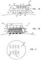
- FIG. 1Ais a schematic, partly sectional illustration of a skin puncturing device 20 for transdermal delivery of an active substance and/or transdermal extraction of an analyte, in accordance with a preferred embodiment of the present invention.
- Device 20comprises a control unit 30 attached to a skin patch 40 , which is preferably fixed to a suitable area of a subject's skin 22 .
- Device 20preferably administers an active substance through the normally substantially-impermeable stratum corneum layer of the skin by passing a controlled electric current therethrough, thereby ablating the stratum corneum and generating micro-channels through which the substance can pass.
- device 20is used to generate micro-channels in the stratum corneum in order to allow passage of molecules to patch 40 from the underlying tissue, generally for diagnostic purposes.
- Control unit 30preferably comprises a switching unit 50 , a battery 52 (such as a lithium coin cell battery), and an optional user-interface comprising buttons 54 and a sensible signal generator 56 , which may comprise a display and/or a buzzer.
- buttons 54initialize and terminate analyte extraction or delivery of the active substance, although buttons 54 preferably also programmably control extraction or dosage rate and duration.
- Patch 40comprises two or more electrodes 60 , preferably an array 75 of electrodes, which pass current into and out of the skin.
- the active substance stored in patch 40flows therethrough.
- the active substanceis preferably stored in or applied to inter-electrode regions 68 and flows directly therefrom into the micro-channels created in the skin.
- Control unit 30containing switching unit 50 and battery 52 , is preferably designed for repeated use, to be removably attached to disposable skin patch 40 .
- control unit 30Before use, control unit 30 is fitted onto patch 40 , and a protective tab (not shown) on the lower surface of patch 40 is preferably removed, exposing the one or more electrodes 60 , and, in drug delivery systems, the active substance.
- One or more optional alignment pins 32are preferably incorporated into control unit 30 and/or skin patch 40 to maintain proper alignment therebetween. Fitting control unit 30 to patch 40 also couples electrical contacts 62 on a lower surface of control unit 30 with electrical contacts 58 on an upper surface of skin patch 40 .
- control unit 30 and skin patch 40are constructed as one integrated unit.
- FIG. 1Bis a schematic, partly sectional illustration of another device 21 for transdermal transport of a substance, in accordance with a preferred embodiment of the present invention.
- Device 21operates in substantially the same manner as device 20 , described hereinabove, but device 21 is preferably used in an add-on configuration with commercially available medical patches.
- a medical patch 74is coupled to a porous, thin, flexible, and disposable electrode patch 70 , which is used to create micro-channels in skin 22 so as to enable enhanced flow of an active substance stored within medical patch 74 through electrode patch 70 and into skin 22 .
- Electrode patch 70is preferably constructed such that electrical contacts 58 thereof are coupled to electrical contacts 62 of control unit 30 and carry charge through flexible leads 76 and 78 internal to patch 70 , in order to create an electric field between electrodes 120 placed against the surface of skin 22 .
- medical patch 74Prior to use, medical patch 74 is placed onto electrode patch 70 , typically on the opposite side of patch 70 from electrodes 120 .
- An adhesive on the underside of medical patch 74preferably secures the two patches together.
- electrode patch 70is folded over, as shown in FIG. 1B, such that an upper surface of patch 74 is secured through an adhesive 72 to electrode patch 70 .
- the active substancepreferably diffuses from the lower surface of patch 74 into, and then through, patch 70 into skin 22 .
- Device 21is thus compatible with a broad range of currently available active or passive medical patches, which are typically of the same general construction (thin shell, internal reservoir of active substance, porous and adhesive-coated undersurface).
- electrode patch 70is not folded over; instead, control unit 30 is placed next to medical patch 74 on top of electrode patch 70 . Further alternatively, control unit 30 has electrical contacts on its upper surface to which are coupled the electrical contacts of the electrical patch.
- FIG. 2is a schematic bottom view of skin patch 40 from FIG. 1A, showing array 75 of electrodes 60 , in accordance with a preferred embodiment of the present invention.
- array 75as shown comprises sixteen electrodes, it is understood that in some implementations the array might be smaller, while in others the array might be larger, for example 50 ⁇ 50 or even more, so as to enable a greater amount of the active substance to be delivered or analyte to be extracted.
- Electrodes 60 in this embodimentare preferably organized into eight electrode sets 77 , such that most of the charge leaving one electrode in a set goes to the other electrode in that set, and generally does not go to electrodes in an adjacent set. Electrode sets 77 are further preferably densely packed in order to maximize the transdermal transfer rate.
- the densitymay range from 4-100 electrode sets/cm 2 .
- Each electrode settypically generates at least one micro-channel before a threshold of current or total charge transfer is passed, responsive to which switching unit 50 preferably causes current to the electrode set to be terminated or reduced, as described herein.
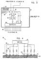
- FIG. 3is a schematic illustration of switching unit 50 in device 20 of FIG. 1A, configured to control a 4 ⁇ 4 array of electrodes 60 , as in FIG. 2, in accordance with a preferred embodiment of the present invention.
- Switching unit 50preferably comprises a CPU 80 which actively controls the voltage V(t) applied to sixteen conductors 90 leading to electrodes 60 .
- CPU 80monitors the current flow, I(t), through each of conductors 90 leading to electrodes 60 in order to determine whether a characteristic of the current (e.g., time-integrated current, I, dI/dt, d 2 I/dt 2 ) has surpassed a threshold, indicating micro-channel formation.
- the CPUterminates current flow to any electrode for which the threshold has been surpassed.
- some of electrodes 60are generally not used to initiate channel formation, but serve primarily to allow CPU 80 and/or other circuitry to monitor electrical properties of skin 22 .
- CPU 80which receives a clock signal from an oscillator 92 , preferably communicates with and controls electrodes 60 through eight data lines 81 and four control lines 85 which lead to an A/D-D/A converter 82 , and by five address lines 84 and four control lines 86 which lead to a multiplexing unit 88 . It will be understood by one skilled in the art that there are many methods to monitor and control current through a plurality of conductors, and that using a CPU, A/D-D/A converter and multiplexing unit as described herein is just one of these.
- data lines 81carry in alternation a low byte and a high byte of data between the CPU and A/D-D/A converter 82 .
- 10 bits of datarepresenting a desired voltage for one of the sixteen electrodes, are converted to an analog voltage in A/D-D/A converter 82 , and this voltage is passed by multiplexing unit 88 to an appropriate electrode, the electrode selection being determined by the binary values represented in address lines 84 .
- fewer than 10 bitsare required to define voltages for the respective electrodes, and circuitry within switching unit 50 is accordingly simpler.
- CPU 80enters a current-sensing mode, wherein switching unit 50 continues to drive current through conductors 90 , but the CPU changes the state of control lines 85 and 86 in order to measure the current flow through conductors 90 .
- multiplexing unit 88measures a current through one of conductors 90 , converts this measurement to a voltage, and passes the voltage to A/D-D/A converter 82 which in turn passes the digital value representing the current to the CPU.
- CPU 80scans through each of the sixteen electrodes, detects a present current flow value, stores this value in an optional memory unit 89 , optionally compares the value with prior values for the same electrode in order to calculate ⁇ I(t)dt, dI/dt and/or d 2 I/dt 2 , and regulates the potential of that electrode responsive to the current measurement and/or optional calculation.
- CPU 80 , oscillator 92 , and memory 89could be replaced by other circuitry able to perform generally the same functions.
- FIG. 4is a schematic illustration of an electrode assembly 94 , comprising a plurality of electrodes 120 , which are placed on skin 22 in order to generate micro-channels in the stratum corneum 100 , in accordance with a preferred embodiment of the present invention.
- Electrodes 120 in assembly 94are grouped in sometimes overlapping sets of two or more electrodes, forming a plurality of electrode sets 124 , one of which is indicated with a dashed line in FIG. 4 .
- Current, coming from switching unit 50generally flows from one electrode in each electrode set to the other electrodes of the set.
- An arrow going between the two electrodes in set 124indicates the preferred flow of current.
- the spacing between electrodes in each electrode setis smaller than about 0.1 mm, although for some applications it may range from (by way of illustration and not limitation) 0.1 mm to about 0.3 mm.
- the distanceis set such that an electric field penetration depth is achieved which is substantially of the same magnitude as the thickness of the stratum corneum, so that the current mostly does not enter epidermal tissue underlying the stratum corneum.
- Experimental resultshave shown that the depth of deepest ablation is generally similar to the electrode spacing, so maintaining the spacing between about 0.01 mm and about 0.1 mm optimizes generation of micro-channels while substantially reducing damage, sensation and/or pain in the innervated dermis and in the epidermal tissue below the stratum corneum.
- the electric field generated between the electrodescan be viewed as having fundamentally two components: a component perpendicular to the skin, which generally causes current flow perpendicular to the skin; and a lateral component, which generally causes current flow parallel to the skin.
- the perpendicular componentis generally large and/or greater than the lateral component.
- the present inventionseeks generally to maximize the ratio of the lateral component to the perpendicular component at the depth corresponding to the interface between the deepest portion of the stratum corneum and the most superficial portion of the remainder of the epidermis.
- tissue ablationoccurs mostly in the stratum corneum, as desired, and largely does not occur in the underlying tissue.
- Electrodes 120directly on skin 22 , typically (a) by stamping the electrodes thereon; (b) by employing a transfer patch of a conductive substance; and/or (c) by other techniques known in the art.
- Switching unit 50preferably sends current to the printed electrodes via printed ports (not shown) on the upper surface of the electrodes.
- the conductive substancepreferably contains an active substance, typically dissolved or suspended therein.
- This “self-quenching” feature of the printed electrodesis typically achieved by controlling fabrication of the electrodes, in particular by regulating the thickness and/or chemical composition thereof.
- Printed electrodes comprising a silver-based emulsion inkpreferably undergo thermal fusion within the ink responsive to high current flow, resulting in a decrease in electrical conduction therethrough.
- switching unit 50monitors current flow to electrodes 60 (or electrodes 120 , shown in FIG. 1 B and subsequent figures), and selectively terminates the flow to one or more electrodes upon a determination that ablation of stratum corneum 100 has occurred.
- a cluster 96 of electrodesis a grouping of electrodes 120 , which are typically in very close mutual proximity, and are therefore assumed to overlie an area of skin 22 which has generally uniform properties.
- cluster sizesgenerally range from about 4 mm 2 to about 100 mm 2 .
- Switching unit 50preferably monitors and terminates the current flow through the electrodes in cluster 96 collectively (i.e. for all of the electrodes, not individually for each electrode).
- current through electrodes 120 in cluster 96is determined by monitoring the current in only a subset of the electrodes, and assuming the value derived therefrom to be generally representative of current through each of the other electrodes. Upon a determination by switching unit 50 that stratum corneum 100 under cluster 96 has been ablated, the current flow to all of the electrodes in cluster 96 is substantially terminated. Monitoring of clusters of electrodes generally simplifies control circuitry associated with the invention, while not substantially decreasing the performance thereof.
- Optional resistive elements 98coupled in series between switching unit 50 and electrodes 120 , limit the power dissipation in the skin following the large increase of conductivity in the epidermis associated with ablation of the stratum corneum.
- Typical values for resistive elements 98range from 1 kohm-100 kOhms, but in some applications may have values outside of this range.
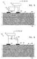
- FIG. 5is a schematic illustration of another electrode assembly 110 , comprising a current source 114 coupled to drive charge through electrodes 120 on skin 22 , in accordance with a preferred embodiment of the present invention.
- Current source 114preferably comprises a source of electrical power (for example, a battery) connected in series with an inductive element which, due to pulse charging, exhibits properties of a current source, thereby limiting the power dissipated in underlying epidermal tissue 102 following the drop in resistance of the epidermis associated with substantially complete ablation of stratum corneum 100 .
- the energy dissipation rateis preferably sufficient to cause electrical breakdown of stratum corneum 100 in a short time, which is typically less than 50 milliseconds, but may range from about 1 to about 1000 milliseconds. Reported values of the voltage needed to break down stratum corneum 100 spread over a range of approximately 5-1000 volts. For the purposes of the present invention, it has been found that an inter-electrode voltage of approximately 100 volts generally ablates stratum corneum 100 without causing significant damage to underlying tissue 102 . It is understood, however, that for some applications or types of subjects/patients, lower or higher inter-electrode voltages may be more suitable.
- an optional voltage sensing unit 112preferably measures the interelectrode voltage and sends a signal corresponding thereto to CPU 80 or other circuitry in switching unit 50 , which regulates the current produced by source 114 responsive to the signal.
- voltage sensing unit 112comprises a comparator which intermittently or continuously compares the interelectrode voltage to a pre-determined threshold value, and signals source 114 when the voltage is below the threshold.
- the CPU, circuitry and/or comparatorpreferably control source 114 to reduce or terminate current flow responsive to a drop of the interelectrode voltage below the threshold value.
- FIG. 6is a schematic illustration of another electrode assembly 130 , comprising a voltage source 136 coupled in series through an optional resistive element 134 to two electrodes 120 on the surface of skin 22 , in accordance with a preferred embodiment of the present invention.
- Optional voltage sensing unit 112measures the voltage drop across resistive element 134 in order to determine the current passing therethrough.
- unit 112 and/or CPU 80 and/or other circuitry in switching unit 50regulate the output of voltage source 136 responsive to the measurement made by unit 112 .
- the voltage drop across element 134exceeds a predetermined threshold value, this is used as an indication of stratum corneum ablation and causes the voltage generated by source 136 to be reduced or terminated responsive thereto.
- optional resistive element 134 and optional voltage sensing unit 112are not used, it is preferable to employ other means for significantly reducing the current flow through electrodes 120 after micro-channel formation. This is preferably done by using “self-quenching” printed electrodes, as described hereinabove with reference to FIG. 4 .
- a conductivity-enhancing substance 132is applied to skin 22 prior to placement of electrodes 120 thereon.
- Substance 132typically improves current flow into skin 22 by decreasing the electrical resistance at the interface between electrodes 120 and skin 22 .
- Experimental resultsindicate that use of substance 132 has the additional desired effect of increasing the above-mentioned ratio of the lateral component of the electric field to the perpendicular component thereof. In particular, it is believed that substance 132 diffuses into stratum corneum 100 and reduces the lateral resistance and lateral breakdown strength of the stratum corneum.
- Substance 132typically comprises a conductive cream, gel and/or ink.
- substance 132additionally comprises a material which has a high diffusion coefficient into the skin and promotes the increased lateral component of the electric field relative to the perpendicular component, as described hereinabove.
- pre-iontophoresisusing a relatively weak electric field, is used to enhance the flow of substance 132 into the outer layer of the skin before application of the stronger electric fields which create the micro-channels. The presence of the conductive substance in the skin subsequent to the pre-iontophoresis is believed to increase the rate of micro-channel creation.
- Pre-iontophoresisis typically implemented by applying, for example, a 3 volt DC field between the electrodes for 30 seconds in order to drive substance 132 into the skin.
- a larger AC current which produces micro-channelsis supplemented by a simultaneous small DC current which supports iontophoresis of substance 132 and thereby enhances micro-channel creation.
- the active substanceis preferably incorporated in substance 132 .
- FIG. 7is a schematic illustration of another electrode assembly 150 , comprising an AC current source 154 coupled in series with an optional resistive element 152 in order to drive current through electrodes 120 and skin 22 , in accordance with a preferred embodiment of the present invention.
- the driving frequency of current through skinhas a significant effect on the sensation or pain experienced by a subject. See, for example, Principles of Applied Biomedical Instrumentation , by L. Geddes and L. Baker, John Wiley & Sons, 1989, which is incorporated herein by reference.
- a 10 kHz driving frequencyhas been found to yield good results, although any frequency between about 100 Hz and about 10 MHz is appropriate for most applications.
- the driving frequencyis cyclically modulated between two endpoints (e.g., 2 kHz and 15 kHz) during application of the electric field, such that a graph representing frequency versus time (not shown) is typically sinusoidal or triangular in character.
- Stratum corneum 100generally displays properties of a simple insulator when exposed to DC current, but displays significant capacitance under AC stimulation, particularly when the driving frequency is above 1 kHz. At these frequencies, current flow through the stratum corneum dissipates energy therein, contributing to the heating and ultimate ablation of the stratum corneum.
- the pre-ablation capacitanceproduces a measurable phase shift between the voltage across the electrodes and the current flowing therebetween, which phase shift is seen to be significantly reduced upon commencement and completion of the ablation of the stratum corneum.
- Sensing unit 112is typically used to detect this phase shift by measuring the inter-electrode voltage, as described hereinabove, and by determining the current flow through electrodes 120 , preferably by measuring the voltage drop across optional resistive element 152 .
- the change of the phase shift from baselineis preferably used by sensing unit 112 and/or CPU 80 and/or other circuitry in switching unit 50 to indicate breakdown of the stratum corneum, responsive to which current flow to electrodes 120 demonstrating such a change preferably is reduced or terminated.
- substance 132is applied to skin 22 , and a DC current is superimposed on the AC current in order to cause iontophoresis of substance 132 during micro-channel creation.
- the duration of charge deliveryis limited by means of an optional ordinary timer circuit (not shown).
- the total charge deliveredis limited using methods known in the art.
- energy storage componentssuch as capacitors and/or inductors can be used to modulate charge delivery.
- passing a threshold of current or voltageis used as an indicator of when to reduce the current applied to the skin
- other functions of the current and/or voltagesuch as derivatives, time-integrals, and/or powers thereof may also be evaluated in order to determine when the current should be reduced.
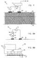
- FIG. 8Ais a schematic illustration of a charge-limited electrode assembly 170 , comprising an electrolyte cell 180 connected in series between a power source 172 and electrodes 120 , in accordance with a preferred embodiment of the present invention.
- Electrolyte cell 180comprises an anode 174 and a cathode 176 , both immersed in an electrolyte solution 178 , which acts as a medium for current flow from anode 174 to cathode 176 .
- cathode 176is steadily consumed by electrolysis until electrolyte cell 180 becomes substantially non-conductive. In this manner, consumption of cathode 176 progresses at a rate which is generally proportional to the current flowing therethrough.
- FIG. 8Bis a schematic illustration of another charge-limited electrode assembly 190 , comprising a power source 192 which sends current to a large-area anode 194 from which it flows through an electrolyte solution 196 to multiple cathodes 202 , in accordance with a preferred embodiment of the present invention.
- the charge-limiting functions embodied in assembly 190are similar to those described with respect to the embodiment shown in FIG. 8 A.
- Anode 194comprises a fibrous material, such as paper, having fibers aligned in a generally vertical direction, perpendicular to the surface of skin 22 .
- anode 194is in very close proximity to cathodes 202 , typically from about 0.1 mm to about 2 mm, in order to enhance independent termination of current through electrodes 198 coupled to cathodes 202 , by reducing lateral conduction within the electrolyte solution.
- FIG. 9is a schematic illustration of yet another charge-limited electrode assembly 210 , comprising a power source 212 in series with a controlled switch 214 , in accordance with a preferred embodiment of the present invention.
- Source 212 and switch 214are connected in series with a capacitor 216 across electrodes 120 , which are applied to skin 22 .
- a typical operational sequence in this preferred embodimentcomprises: (a) turning on source 212 ; (b) closing switch 214 , which results in substantially all of the current from source 212 going through and charging low-impedance capacitor 216 ; (c) opening switch 214 and turning off source 212 ; (d) allowing the discharge from capacitor 216 to drive the ablation of the stratum corneum; and (e) passively terminating the process responsive to complete discharge of capacitor 216 .
- FIG. 10is a schematic illustration of still another charge-limited electrode assembly 220 , comprising an AC source 222 coupled in series to an electrolyte cell 230 , electrode 120 , and skin 22 , in accordance with a preferred embodiment of the present invention.
- Cell 230preferably comprises two alternating nodes 226 and 236 and a common node 240 , all nodes being immersed in an electrolyte solution 232 . Except as will be described below, the function of electrolyte cell 230 is substantially similar to that of electrolytic charge-limiting devices described hereinabove with reference to FIGS. 8A and 8B.
- AC source 222produces a voltage difference across electrodes 120 (only one electrode is shown), which cycles between positive and negative phases at a pre-determined frequency, in order to provide the energy to ablate stratum corneum 100 in skin 22 .
- a diode 224 in electrolyte cell 230passes current to cause alternating node 226 to act as an anode and common node 240 to act as a cathode, which is subsequently consumed by the electrolysis thereof during each positive phase.
- diode 224blocks conduction through alternating node 226 , halting the consumption of common node 240 associated with the positive phase.
- a second diode 234passes current which allows alternating node 236 to act as a cathode (which is consumed) and common node 240 to act as an anode.
- alternating node 236to act as a cathode (which is consumed)
- common node 240to act as an anode.
- the properties of electrolyte cell 230are determined so that the cell becomes non-conductive after passing a quantity of charge which correlates with breakdown of the stratum corneum.
- FIGS. 11A and 11Bare, respectively, a schematic side view of a concentric electrode assembly 250 and a schematic top view of a common electrode layer 252 in assembly 250 , in accordance with a preferred embodiment of the present invention.
- a substantially non-conductive substrate 260overlies common electrode layer 252 .
- Perforations 254 in layer 252allow passage therethrough of electrodes 262 , which receive charge through optional resistive members 256 from a charging bus 264 overlying substrate 260 .
- Electrodes 262which preferably comprise a plurality of conductive fibers, are electrically coupled to skin 22 , and cause charge to pass into skin 22 and subsequently out of skin 22 through common electrode layer 252 , in order to ablate stratum corneum 100 .
- one or more pores 266 traversing substrate 260allow flow of active substances/analytes through substrate 260 from/to a reservoir (not shown) above substrate 260 . It is noted that fabrication of concentric electrode assembly 250 is substantially similar to the process of flexible printed circuit production, which is well known in the art.
- FIG. 12is a schematic, partly sectional illustration of a handheld device 400 for ablating stratum corneum 100 , prior to delivery of an active substance to skin 22 and/or extraction of an analyte from the skin, in accordance with a preferred embodiment of the present invention.
- Device 400preferably comprises a handle 302 , to which is attached a control unit 308 , a display 304 , a speaker 306 , and an ablation head 402 .
- the userslides ablation head 402 along the surface of skin 22 , and electrodes 320 on the ablation head are driven by control unit 308 to form micro-channels in stratum corneum 100 , typically using techniques described hereinabove.
- control unit 308may apply 1 , 500 volts between two of electrodes 320 for a specified amount of time, so as to drive a current determined to be sufficient to generate the micro-channels (i.e., open-loop feedback).
- control unit 308may utilize closed-loop feedback techniques known in the art or as described hereinabove, to determine when to terminate the current.
- the contact region of each electrode on skin 22is a circle having a diameter between about 10 and 100 microns.
- This rangeis particularly suited for producing the very localized ablation desired by some embodiments of the present invention. It is noted that this size range is significantly different from other drug delivery techniques, such as electroporation, in which the contact area of electrodes on the skin may be, for example, 2 cm 2 .
- ablation head 402comprises an accelerometer or other mechanical disposition sensor 312 , coupled to control unit 308 , to enable the control unit to compute the velocity and distance traveled by device 400 . If appropriate, velocity readings are displayed to the user on display 304 and/or output through speaker 306 , for example, with one of the following messages: “Too slow,” “Speed OK,” or “Too fast.”
- mechanical disposition sensor 312comprises a force transducer, and control unit 308 is adapted to drive current through electrodes 320 only if the force between device 400 and skin 22 is above a minimum threshold.
- a pre-moistened medical patch of a known sizeis to be applied to the skin subsequent to ablation thereof by device 400 .
- control unit 308preferably operates in a mode that prevents current flow to electrodes 320 after the device has ablated a user-specified distance on the skin.
- the distance traveled by device 400is displayed to the user on display 304 such that he/she can pass device 400 over a desired distance, treating a specified length of skin, and then stop when the desired distance has been treated.
- ⁇ Ablation head 402preferably comprises an ink reservoir 326 , coupled to the surface of the ablation head by an ink conduit 328 , such that areas of skin 22 in which micro-channels are formed are demarcated by a deposit of ink.
- a pre-moistened ink pad(not shown) is affixed to ablation head 402 .
- the treated area of skin 22is clearly identifiable to the user.
- visible dimplesare temporarily formed on skin 22 by protrusive elements on ablation head 402 , as device 400 is passed over the skin.
- electrodes 320may be shaped to form the protrusive elements.
- the protrusive elementsare integrated into the outer surface of ablation head 402 , or elsewhere on device 400 .
- device 400only applies current to skin 22 if the force applied by the device onto the skin is greater than a threshold expected to produce such visible dimples.
- FIG. 13is a schematic, partly sectional illustration of a handheld device 300 for transdermal delivery of an active substance and/or transdermal analyte extraction, in accordance with a preferred embodiment of the present invention.
- Device 300preferably comprises handle 302 , to which is attached control unit 308 , display 304 , speaker 306 , and an ablation head 342 . Except for differences described hereinbelow, device 300 is typically constructed in a manner substantially similar to device 400 .
- Ablation head 342preferably rotates as it moves across skin 22 , causing one or more pairs of adjacent electrodes 320 to repeatedly come into contact and out of contact with the skin.
- electrodes 320are driven by control unit 308 to form micro-channels in stratum corneum 100 as the ablation head moves along skin 22 .
- a porous material 322is affixed between or in a vicinity of adjacent electrodes 320 .
- Porous material 322is typically used for delivery of an active substance to the surface of skin 22 , in the region of the micro-channels formed by electrodes 320 .
- porous material 322is used to extract molecules from the underlying tissue, which pass through the newly-formed micro-channels, generally for diagnostic purposes.
- Porous material 322is typically selected using criteria such as the size or other characteristics of the molecules of active substance or analyte, and the desired rate of transfer of the active substance or analyte.
- ablation head 342comprises a drug reservoir 314 , which is preferably reusable, such that it can be refilled with an active substance for subsequent treatments.
- Drug reservoir 314preferably comprises a reservoir gauge 346 to determine the amount of active substance remaining in drug reservoir 314 .
- the output of gauge 346is passively displayed, e.g., through a window on the reservoir.
- a gauge output signalis passed to control unit 308 , and logic in the control unit processes the signal so as to determine the amount of active substance remaining in drug reservoir 314 and/or the amount of active substance administered in the current application of device 300 .
- This informationis preferably presented to the user on display 304 .
- an audio signal from speaker 306informs the user when the drug reservoir is empty, indicates when a desired quantity of active substance has been delivered to skin 22 , or conveys other relevant information regarding the status of device 300 .
- drug reservoir 314comprises a reservoir pump 344 , which is driven by control unit 308 so as to regulate the flow rate of the active substance to porous material 322 .
- the flow of active substance produced by reservoir pump 344forms a spray of active substance at the exit of a drug conduit 316 leading from the reservoir.
- the sprayin turn, coats the ablated region of skin 22 with the active substance. Consequently, porous material 322 may be eliminated in this embodiment.
- a hole in porous material 322allows the spray to pass therethrough, while the surrounding porous material absorbs any active substance not initially absorbed into skin 22 , and keeps the substance in contact with the skin for later absorption.
- the drugis administered in another form, e.g., as a powder or a gel pre-applied around the electrodes.
- Ablation head 342typically comprises a position sensor 310 , coupled to measure the angular position of the ablation head and to send a signal responsive thereto to control unit 308 .
- the control unitpreferably determines the velocity and position of device 300 , and outputs instructions to the user based on these determinations, as described hereinabove.
- the angular position of the ablation headis used by the control unit in regulating the timing of the application of electric current to electrodes 320 .
- porous material 322is actively wetted with the active substance an appropriate amount of time or distance before the porous material comes in contact with the skin. This is particularly useful if the active substance has a high evaporation rate, and/or if the substance is applied to the skin as a spray.
- FIG. 14is a schematic, partly sectional illustration of a device 380 for transdermal delivery of an active substance or transdermal analyte extraction, in accordance with another preferred embodiment of the present invention.
- Device 380preferably operates in substantially the same manner as device 300 , described hereinabove with reference to FIG. 13, but device 380 utilizes different apparatus for delivering the active substance to the surface of skin 22 . Whereas in device 300 the means for active substance delivery are integrated into ablation head 342 , device 380 includes separate apparatus for delivering the active substance to skin 22 .
- Device 380preferably comprises a rocker arm 362 , coupled between ablation head 366 and a drug delivery spool 360 .
- ablation head 366is free to rotate as device 380 is moved across the surface of the skin, causing electrodes 320 to repeatedly come into and out of contact with the skin such that micro-channels are formed in the stratum corneum, as described hereinabove.
- Drug delivery spool 360is coupled to rocker arm 362 such that the spool is free to rotate as device 380 moves across skin 22 .
- the active substanceis delivered to the ablated region of the skin by means of a drug delivery strip 358 to which the active substance has been pre-applied (e.g., at the time of manufacture).
- strip 358preferably holds the strip in place on the ablated region of the skin.
- strip 358 and spool 360are combined as a single disposable unit, so that prior to use, the user attaches the pre-wound spool to rocker arm 362 .
- drug delivery strip 358is wound around drug delivery spool 360 by the user, such that spool 360 is reusable while strip 358 is disposable.
- strip 358is divided into a number of sections, corresponding to individual patches, each containing one dose of the drug, such that as the user passes device 380 over skin 22 , one patch is placed onto the skin. Thereafter, the patch is preferably separated from the strip at a line of perforations (not shown).
- the active substanceis uniformly applied to drug delivery strip 358 .
- the active substanceis applied at discrete locations 356 on drug delivery strip 358 .
- the delivery stripis preferably applied to the ablated region of skin 22 in a manner which aligns locations 356 with ablation sites 354 in skin 22 induced by ablation head 366 .
- FIG. 14illustrates device 380 in a configuration in which ablation head 366 precedes drug delivery spool 360 as device 380 is moved across the skin. It is to be understood, however, that alternative embodiments may include a drug delivery spool preceding ablation head 342 as the device moves over the skin. In such a case, electrodes 320 typically either puncture drug delivery strip 358 or protrude through pre-formed holes (not shown) in the delivery strip prior to ablating skin 22 .
- strip 358is itself wound around ablation head 366 , such that the act of rolling the ablation head over skin 22 both triggers electrodes protruding through holes in the strip to create the micro-channels, and also causes the strip to unwind from the ablation head and remain in contact with the skin.
- the active substanceis in contact with the skin as electrodes 320 form micro-channels in the skin, which may be preferable for certain applications.
- FIG. 15is a schematic, partly sectional illustration of a device 390 for transdermal delivery of an active substance or transdermal analyte extraction, in accordance with a preferred embodiment of the present invention.
- Device 390preferably operates in substantially the same manner as device 380 , described hereinabove with reference to FIG. 14, but device 390 has different means for delivering the active substance to the surface of skin 22 .
- device 390comprises a drug delivery head 348 , coupled to handle 302 , for delivery of the active substance to the surface of the skin.
- drug delivery head 348comprises a drug reservoir 392 containing the active substance, and a porous material 322 through which the active substance flows during operation of device 390 .
- a desired flow rate of the active substanceis typically achieved under the influence of gravity and/or capillary action in porous material 322 .
- drug reservoir 392comprises a reservoir pump 394 coupled to control unit 308 , so as to allow the flow rate of the active substance to be actively controlled, as described hereinabove.
- porous material 322typically slides along skin 22 as device 390 is moved over the skin.
- drug delivery head 348is coupled to rotate as device 390 moves along the skin.
- FIG. 16is a schematic pictorial illustration of a device 500 for transdermal delivery of an active substance or transdermal analyte extraction, in accordance with a preferred embodiment of the present invention.
- Device 500preferably operates in a generally similar manner to that described hereinabove with reference to FIGS. 12-15, except as noted below.
- Device 500preferably comprises an ablation head 510 having a large number of small “monopolar” electrodes 512 disposed thereon.
- one or more larger return electrodes 514are preferably disposed on ablation head 510 , and serve as a return conduit for current driven through the skin by electrodes 512 .
- any of the drug delivery or analyte extraction devices described hereinabovemay similarly comprise a plurality of current-driving electrodes and one or more return electrodes.
- monopolar devicestend to produce ablation of the stratum corneum directly under and immediately adjacent to the site of each current-driving electrode. Because of the typically larger size of the return electrodes, there is usually no substantial heating of the skin thereunder.
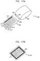
- FIGS. 17A and 17Bare schematic illustrations of apparatus 600 for enabling transdermal transport of a substance, in accordance with a preferred embodiment of the present invention. Except for differences described hereinbelow, apparatus 600 is preferably configured to operate generally in accordance with some or all of the techniques described herein for ablating stratum corneum.
- a handheld unit including at least one high-voltage driving electrode 650 , a return electrode 652 , and a power source (not shown)is passed by the user over a patch 602 , which typically comprises a set of monopolar receiving electrodes 610 and a return strip 614 .
- Electrodes 610 and return strip 614preferably pass through patch 620 from the top surface thereof (FIG. 17A) to the bottom surface thereof (FIG. 17 B), so as to contact skin 22 when the patch is placed on the skin.
- the electrodesare configured by other means to electrically connect the top and bottom surfaces of patch 620 .
- driving electrode 650preferably comes into contact with each of receiving electrodes 610 , and drives current through these electrodes into skin 22 .
- return electrode 652makes contact with return strip 614 on patch 602 , allowing current injected into skin 22 to return to the handheld unit.
- the currentis configured so as to produce local ablation at the contact sites of each of electrodes 610 with skin 22 . There is typically no substantial heating where return strip 614 contacts the skin, because the strip preferably has a significantly larger contact area than the total contact area of each of electrodes 610 .
- each of electrodes 610 on patch 602is arranged such that as the handheld unit is passed over the patch, driving electrode 650 makes simultaneous contact with a desired number of electrodes 612 before contacting a subsequent group of one or more electrodes 613 .
- electrodes 610may be arranged in: (a) a staggered grid (FIGS. 17 A and 17 B), (b) a rectangular grid, with one or more electrodes in each dimension, or (c) a line parallel to return strip 614 , so as to allow only one electrode to be contacted at a time.
- other geometriesare used so as to provide contact, at any given time, between one or more of electrodes 610 and driving electrode 650 .
- the shape of the surface of patch 602is configured in accordance with the desired motion of the handheld unit.
- return strip 614may be recessed into the surface of the patch, in a manner which facilitates desired contact between the handheld unit and the patch.
- the power sourcemay be configured to apply the current such that two or more passes of the handheld unit over the patch produce the desired extent of ablation of the stratum corneum. It is noted that although the handheld unit is shown in FIGS. 17A and 17B as being configured for manual operation, automated means may also be provided for moving driving electrode 650 over each of electrodes 610 on patch 602 .
Landscapes
- Health & Medical Sciences (AREA)
- Engineering & Computer Science (AREA)
- Biomedical Technology (AREA)
- Nuclear Medicine, Radiotherapy & Molecular Imaging (AREA)
- Radiology & Medical Imaging (AREA)
- Life Sciences & Earth Sciences (AREA)
- Animal Behavior & Ethology (AREA)
- General Health & Medical Sciences (AREA)
- Public Health (AREA)
- Veterinary Medicine (AREA)
- Electrotherapy Devices (AREA)
- Media Introduction/Drainage Providing Device (AREA)
- Measurement Of The Respiration, Hearing Ability, Form, And Blood Characteristics Of Living Organisms (AREA)
- External Artificial Organs (AREA)
Abstract
Description
Claims (20)
Priority Applications (12)
| Application Number | Priority Date | Filing Date | Title |
|---|---|---|---|
| US09/840,522US6708060B1 (en) | 1998-11-09 | 2001-04-23 | Handheld apparatus and method for transdermal drug delivery and analyte extraction |
| EP04105508AEP1502622B1 (en) | 2001-04-23 | 2002-04-22 | Handheld apparatus for transdermal drug delivery and analyte extraction |
| AT04105508TATE434464T1 (en) | 2001-04-23 | 2002-04-22 | HAND-HELD DEVICE FOR TRANSDERMAL ADMINISTRATION OF MEDICATIONS AND FOR EXTRACTION OF BODY FLUID |
| DE60232747TDE60232747D1 (en) | 2001-04-23 | 2002-04-22 | Hand device for the transdermal administration of medicaments and for the removal of body fluids |
| CA002445118ACA2445118A1 (en) | 2001-04-23 | 2002-04-22 | Handheld apparatus and method for transdermal drug delivery and analyte extraction |
| EP02764094AEP1397178A2 (en) | 2001-04-23 | 2002-04-22 | Handheld apparatus and method for transdermal drug delivery and analyte extraction |
| AU2002307781AAU2002307781B2 (en) | 2001-04-23 | 2002-04-22 | Handheld apparatus for transdermal drug delivery and analyte extraction |
| JP2002583024AJP4262985B2 (en) | 2001-04-23 | 2002-04-22 | Hand-held device and method for transdermal drug delivery and analyte extraction |
| IL15858202AIL158582A0 (en) | 2001-04-23 | 2002-04-22 | Handheld apparatus and method for transdermal drug delivery and analyte extraction |
| PCT/IL2002/000319WO2002085451A2 (en) | 2001-04-23 | 2002-04-22 | Handheld apparatus for transdermal drug delivery and analyte extraction |
| IL158582AIL158582A (en) | 2001-04-23 | 2003-10-23 | Handheld apparatus for transdermal drug delivery and analyte extraction |
| US10/775,725US7164942B2 (en) | 1998-11-09 | 2004-02-09 | Handheld apparatus and method for transdermal drug delivery and analyte extraction |
Applications Claiming Priority (3)
| Application Number | Priority Date | Filing Date | Title |
|---|---|---|---|
| US09/189,170US6148232A (en) | 1998-11-09 | 1998-11-09 | Transdermal drug delivery and analyte extraction |
| US09/635,892US6615079B1 (en) | 1998-11-09 | 2000-08-10 | Transdermal drug delivery and analyte extraction |
| US09/840,522US6708060B1 (en) | 1998-11-09 | 2001-04-23 | Handheld apparatus and method for transdermal drug delivery and analyte extraction |
Related Parent Applications (1)
| Application Number | Title | Priority Date | Filing Date |
|---|---|---|---|
| US09/635,892Continuation-In-PartUS6615079B1 (en) | 1998-11-09 | 2000-08-10 | Transdermal drug delivery and analyte extraction |
Related Child Applications (1)
| Application Number | Title | Priority Date | Filing Date |
|---|---|---|---|
| US10/775,725ContinuationUS7164942B2 (en) | 1998-11-09 | 2004-02-09 | Handheld apparatus and method for transdermal drug delivery and analyte extraction |
Publications (1)
| Publication Number | Publication Date |
|---|---|
| US6708060B1true US6708060B1 (en) | 2004-03-16 |
Family
ID=25282592
Family Applications (2)
| Application Number | Title | Priority Date | Filing Date |
|---|---|---|---|
| US09/840,522Expired - LifetimeUS6708060B1 (en) | 1998-11-09 | 2001-04-23 | Handheld apparatus and method for transdermal drug delivery and analyte extraction |
| US10/775,725Expired - Fee RelatedUS7164942B2 (en) | 1998-11-09 | 2004-02-09 | Handheld apparatus and method for transdermal drug delivery and analyte extraction |
Family Applications After (1)
| Application Number | Title | Priority Date | Filing Date |
|---|---|---|---|
| US10/775,725Expired - Fee RelatedUS7164942B2 (en) | 1998-11-09 | 2004-02-09 | Handheld apparatus and method for transdermal drug delivery and analyte extraction |
Country Status (9)
| Country | Link |
|---|---|
| US (2) | US6708060B1 (en) |
| EP (2) | EP1502622B1 (en) |
| JP (1) | JP4262985B2 (en) |
| AT (1) | ATE434464T1 (en) |
| AU (1) | AU2002307781B2 (en) |
| CA (1) | CA2445118A1 (en) |
| DE (1) | DE60232747D1 (en) |
| IL (1) | IL158582A0 (en) |
| WO (1) | WO2002085451A2 (en) |
Cited By (78)
| Publication number | Priority date | Publication date | Assignee | Title |
|---|---|---|---|---|
| US20040127962A1 (en)* | 1993-10-04 | 2004-07-01 | Huan-Chen Li | Medical device for treating skin itch and rash |
| US20040258723A1 (en)* | 2001-05-01 | 2004-12-23 | Parminder Singh | Hydrogel compositions demonstrating phase separation on contact with aqueous media |
| US20050038388A1 (en)* | 2001-10-18 | 2005-02-17 | Edgar Hommann | Injection device comprising an energy storage device |
| US20050119605A1 (en)* | 2002-04-19 | 2005-06-02 | Transpharma Medical Ltd. | Handheld transdermal drug delivery and analyte extraction |
| US20050165393A1 (en)* | 1996-12-31 | 2005-07-28 | Eppstein Jonathan A. | Microporation of tissue for delivery of bioactive agents |
| US20050222565A1 (en)* | 2004-04-01 | 2005-10-06 | Dieter Manstein | Method and apparatus for dermatological treatment and tissue reshaping |
| US20060034905A1 (en)* | 2004-08-05 | 2006-02-16 | Parminder Singh | Adhesive composition |
| US20060167403A1 (en)* | 2000-03-10 | 2006-07-27 | Biophoretic Therapeutic Systems, Llc | Electrokinetic delivery system for self-administration of medicaments and methods therefor |
| US20060184093A1 (en)* | 2002-06-28 | 2006-08-17 | Alza Corporation | Methods of electrotransport drug delivery |
| US20060233871A1 (en)* | 2002-10-31 | 2006-10-19 | Meir Stern | Transdermal delivery system for dried particulate or lyophilized medications |
| US20070009542A1 (en)* | 2005-07-05 | 2007-01-11 | Galit Levin | Method and device for transdermal immunization |
| US20070031495A1 (en)* | 2005-06-17 | 2007-02-08 | Jonathan Eppstein | Permeant delivery system and methods for use thereof |
| US20070049998A1 (en)* | 2005-05-18 | 2007-03-01 | Tyrell, Inc. | Treatment device and method for treating skin lesions through application of heat |
| US20070078502A1 (en)* | 2005-10-05 | 2007-04-05 | Thermage, Inc. | Method and apparatus for estimating a local impedance factor |
| US20070082040A1 (en)* | 2002-10-31 | 2007-04-12 | Meir Stern | Transdermal delivery system for dried particulate or lyophilized peptides and polypeptides |
| US20070083247A1 (en)* | 2005-10-11 | 2007-04-12 | Thermage, Inc. | Electrode assembly and handpiece with adjustable system impedance, and methods of operating an energy-based medical system to treat tissue |
| US20070088413A1 (en)* | 2005-10-19 | 2007-04-19 | Thermage, Inc. | Treatment apparatus and methods for delivering energy at multiple selectable depths in tissue |
| WO2007056105A2 (en) | 2005-11-02 | 2007-05-18 | Transpharma Medical Ltd. | Human growth hormone patch formulations |
| WO2007062266A2 (en) | 2005-11-28 | 2007-05-31 | Marinus Pharmaceuticals | Ganaxolone formulations and methods for the making and use thereof |
| US20070128420A1 (en)* | 2005-12-07 | 2007-06-07 | Mariam Maghribi | Hybrid composite for biological tissue interface devices |
| US20070260170A1 (en)* | 2004-11-18 | 2007-11-08 | Galit Levin | Combined micro-channel generation and iontophoresis for transdermal delivery of pharmaceutical agents |
| US20070259316A1 (en)* | 2006-05-08 | 2007-11-08 | Tyrell, Inc. | Treatment device and method for treating or preventing periodontal disease through application of heat |
| US20070270732A1 (en)* | 2003-06-23 | 2007-11-22 | Transpharma Medical Ltd. | Transdermal Delivery System for Cosmetic Agents |
| US20070287949A1 (en)* | 2003-12-09 | 2007-12-13 | Transpharma Medical Ltd. | Transdermal System for Sustained Delivery of Polypeptides |
| US20070292445A1 (en)* | 2004-07-06 | 2007-12-20 | Transpharma Medical Ltd. | Delivery system for transdermal immunization |
| US20080008978A1 (en)* | 2006-05-08 | 2008-01-10 | Tyrell, Inc. | Treatment device and method for treating or preventing periodontal disease through application of heat |
| US20080009923A1 (en)* | 2006-06-14 | 2008-01-10 | Paithankar Dilip Y | Treatment of Skin by Spatial Modulation of Thermal Heating |
| US20080114281A1 (en)* | 2004-01-25 | 2008-05-15 | Transpharma Medical Ltd. | Transdermal Delivery System for Polynucleotides |
| WO2008066899A2 (en) | 2006-11-28 | 2008-06-05 | Marinus Pharmaceuticals | Nanoparticulate formulations and methods for the making and use thereof |
| US20080161492A1 (en)* | 2001-05-01 | 2008-07-03 | Cleary Gary W | Two-phase, water-absorbent bioadhesive composition |
| US20080234626A1 (en)* | 2006-04-26 | 2008-09-25 | Chelak Todd M | Multi-stage microporation device |
| WO2008131072A1 (en)* | 2007-04-17 | 2008-10-30 | Transport Pharmaceuticals, Inc. | Current density detection and control system and method for an electrokinetic delivery of medicaments |
| US20080269735A1 (en)* | 2007-04-26 | 2008-10-30 | Agustina Vila Echague | Optical array for treating biological tissue |
| US20080274166A1 (en)* | 2005-06-10 | 2008-11-06 | Transpharma Medical Ltd. | Patch for Transdermal Drug Delivery |
| US20080287943A1 (en)* | 2007-01-25 | 2008-11-20 | Thermage, Inc. | Treatment apparatus and methods for inducing microburn patterns in tissue |
| US20090018628A1 (en)* | 2007-07-10 | 2009-01-15 | Thermage, Inc. | Treatment apparatus and methods for delivering high frequency energy across large tissue areas |
| US20090137480A1 (en)* | 2002-10-31 | 2009-05-28 | Meir Stern | Transdermal delivery system for dried particulate or lyophilized medications |
| US20090192503A1 (en)* | 2008-01-24 | 2009-07-30 | Haim Epshtein | Device, apparatus, and method of adipose tissue treatment |
| US20100016849A1 (en)* | 2008-07-16 | 2010-01-21 | Avner Rosenberg | Rf electrode for aesthetic and body shaping devices and method of using same |
| US20100016761A1 (en)* | 2008-07-16 | 2010-01-21 | Avner Rosenberg | Applicator for skin treatement with automatic regulation of skin protrusion magnitude |
| US20100185193A1 (en)* | 2004-09-01 | 2010-07-22 | Michael Kreindel | Method and system for invasive skin treatment |
| US20100198134A1 (en)* | 2008-01-17 | 2010-08-05 | Shimon Eckhouse | Hair removal apparatus for personal use and the method of using same |
| WO2010097790A1 (en)* | 2009-02-25 | 2010-09-02 | Transpharma Medical Ltd. | Electrical skin rejuvenation |
| US20100229636A1 (en)* | 2007-10-17 | 2010-09-16 | Galit Levin | Dissolution rate verification |
| US20100278757A1 (en)* | 2001-05-01 | 2010-11-04 | Feldstein Mikhail M | Water-Absorbent Adhesive Compositions and Associated Methods of Manufacture and Use |
| US20100286588A1 (en)* | 2007-10-09 | 2010-11-11 | Transpharma Ltd. | Magnetic patch coupling |
| US20100291186A1 (en)* | 2009-01-14 | 2010-11-18 | Parminder Singh | Transdermal Administration of Tamsulosin |
| US20100293807A1 (en)* | 2007-10-29 | 2010-11-25 | Transpharma Medical, Ltd. | Vertical patch drying |
| US20110009782A1 (en)* | 2009-07-07 | 2011-01-13 | Naya Touch, Inc. | Dermal roller with therapeutic microstructures |
| US20110150976A1 (en)* | 2008-09-10 | 2011-06-23 | Transpharma Medical Ltd. | Transdermal delivery of oligosaccharides |
| US20110166559A1 (en)* | 2008-09-21 | 2011-07-07 | Shimon Eckhouse | Method and apparatus for personal skin treatment |
| US20110190688A1 (en)* | 2008-03-31 | 2011-08-04 | Frank Tagliaferri | Permeant Delivery System and Methods for Use Thereof |
| US20110190655A1 (en)* | 2008-08-27 | 2011-08-04 | Ulrich Moissl | Scanning head including at least two electrodes for impedance measurement, arrangement, and related method |
| US8182475B2 (en) | 2003-05-31 | 2012-05-22 | Lumatherm, Inc. | Methods and devices for the treatment of skin lesions |
| USRE44145E1 (en) | 2000-07-07 | 2013-04-09 | A.V. Topchiev Institute Of Petrochemical Synthesis | Preparation of hydrophilic pressure sensitive adhesives having optimized adhesive properties |
| US8481059B2 (en) | 2001-05-01 | 2013-07-09 | A.V. Topchiev Institute Of Petrochemical Synthesis, Russian Academy Of Sciences | Hydrogel compositions |
| US8481071B2 (en) | 2001-05-01 | 2013-07-09 | Corium International, Inc. | Hydrogel compositions with an erodible backing member |
| US8496654B2 (en) | 2009-07-20 | 2013-07-30 | Syneron Medical Ltd. | Method and apparatus for fractional skin treatment |
| US8517958B2 (en) | 1999-06-08 | 2013-08-27 | Nitto Denko Corporation | Transdermal integrated actuator device, methods of making and using same |
| US8641689B2 (en) | 2002-03-11 | 2014-02-04 | Nitto Denko Corporation | Transdermal porator and patch system and method for using same |
| US8658201B2 (en) | 2004-01-30 | 2014-02-25 | Corium International, Inc. | Rapidly dissolving film for delivery of an active agent |
| US20140194949A1 (en)* | 2013-01-04 | 2014-07-10 | Brian D. Wichner | Multiplex Electrodes for Applying Transcutaneous Interferential Current |
| US8821901B2 (en) | 2001-05-01 | 2014-09-02 | A.V. Topchiev Institute Of Petrochemical Synthesis Russian Academy Of Sciences | Method of preparing polymeric adhesive compositions utilizing the mechanism of interaction between the polymer components |
| US9011419B2 (en) | 2007-12-05 | 2015-04-21 | Syneron Medical Ltd | Disposable electromagnetic energy applicator |
| US9033950B2 (en) | 2003-10-24 | 2015-05-19 | Nitto Denko Corporation | Method for transdermal delivery of permeant substances |
| US20150246227A1 (en)* | 2012-10-05 | 2015-09-03 | Shiseido Company, Ltd. | Cosmetic device, method of applying current, and storage medium |
| US9210985B2 (en) | 2013-06-19 | 2015-12-15 | Gilad Arwatz | Electromechanical system for dispensing deodorant / antiperspirant |
| US9504826B2 (en) | 2009-02-18 | 2016-11-29 | Syneron Medical Ltd | Skin treatment apparatus for personal use and method for using same |
| US9532935B2 (en) | 2001-05-01 | 2017-01-03 | A. V. Topchiev Institute of Petrochemical Synthesis, Russian Academy of Sciences | Hydrogel compositions for tooth whitening |
| US20170239454A1 (en)* | 2014-09-03 | 2017-08-24 | University Of Strathclyde | Apparatus for topical application of material |
| US9770560B2 (en) | 2009-11-12 | 2017-09-26 | Pourang Bral | Means and method to administer injections with little or no pain |
| US9839644B2 (en) | 2014-09-09 | 2017-12-12 | ARKAY Therapeutics, LLC | Formulations and methods for treatment of metabolic syndrome |
| US9908140B2 (en) | 2013-06-19 | 2018-03-06 | Gilad Arwatz | Electromechanical system for dispensing a composition |
| CN108290040A (en)* | 2015-11-06 | 2018-07-17 | Seb公司 | Device for applying the product to be dispensed to the user's skin by iontophoresis |
| US10226586B2 (en) | 2011-05-26 | 2019-03-12 | Pourang Bral | Means and method to painlessly puncture skin |
| EP3677252A1 (en) | 2012-03-19 | 2020-07-08 | Cidara Therapeutics, Inc. | Dosing regimens for echinocandin class compounds |
| US10973994B2 (en) | 2013-09-16 | 2021-04-13 | Pourang Bral | Means and method to invade skin, mucosa, and underlying tissues with little or no pain |
| CN114081499A (en)* | 2021-11-23 | 2022-02-25 | 吉林大学 | A kind of flexible gas permeable surface electromyography electrode with two gradient pores and preparation method thereof |
Families Citing this family (82)
| Publication number | Priority date | Publication date | Assignee | Title |
|---|---|---|---|---|
| IL152575A (en) | 2002-10-31 | 2008-12-29 | Transpharma Medical Ltd | Transdermal delivery system for water insoluble drugs |
| IL152574A (en) | 2002-10-31 | 2009-09-22 | Transpharma Medical Ltd | Transdermal delivery system for dried particulate or lyophilized medications |
| IL152573A (en) | 2002-10-31 | 2009-11-18 | Transpharma Medical Ltd | Transdermal delivery system for anti-emetic medication |
| JP4381705B2 (en)* | 2003-03-26 | 2009-12-09 | シスメックス株式会社 | Transcutaneous analyte extraction system and analysis system, and transcutaneous analyte extraction method and analysis method |
| US8690865B2 (en)* | 2004-05-28 | 2014-04-08 | Georgia Tech Research Corporation | Methods and devices for thermal treatment |
| US20060089637A1 (en) | 2004-10-14 | 2006-04-27 | Werneth Randell L | Ablation catheter |
| US8096303B2 (en) | 2005-02-08 | 2012-01-17 | Koninklijke Philips Electronics N.V | Airway implants and methods and devices for insertion and retrieval |
| US8371307B2 (en) | 2005-02-08 | 2013-02-12 | Koninklijke Philips Electronics N.V. | Methods and devices for the treatment of airway obstruction, sleep apnea and snoring |
| US8836513B2 (en) | 2006-04-28 | 2014-09-16 | Proteus Digital Health, Inc. | Communication system incorporated in an ingestible product |
| US8802183B2 (en) | 2005-04-28 | 2014-08-12 | Proteus Digital Health, Inc. | Communication system with enhanced partial power source and method of manufacturing same |
| US8912908B2 (en) | 2005-04-28 | 2014-12-16 | Proteus Digital Health, Inc. | Communication system with remote activation |
| US9198608B2 (en) | 2005-04-28 | 2015-12-01 | Proteus Digital Health, Inc. | Communication system incorporated in a container |
| US8730031B2 (en) | 2005-04-28 | 2014-05-20 | Proteus Digital Health, Inc. | Communication system using an implantable device |
| EP3827747A1 (en) | 2005-04-28 | 2021-06-02 | Otsuka Pharmaceutical Co., Ltd. | Pharma-informatics system |
| US8547248B2 (en) | 2005-09-01 | 2013-10-01 | Proteus Digital Health, Inc. | Implantable zero-wire communications system |
| US7634314B2 (en)* | 2005-11-30 | 2009-12-15 | Ak Beauty Enterprises, Llc | Powered stimulation device |
| US20070288078A1 (en)* | 2006-03-17 | 2007-12-13 | Steve Livneh | Apparatus and method for skin tightening and corrective forming |
| JP2009544338A (en) | 2006-05-02 | 2009-12-17 | プロテウス バイオメディカル インコーポレイテッド | Treatment regimen customized to the patient |
| EP2087589B1 (en) | 2006-10-17 | 2011-11-23 | Proteus Biomedical, Inc. | Low voltage oscillator for medical devices |
| SG175681A1 (en) | 2006-10-25 | 2011-11-28 | Proteus Biomedical Inc | Controlled activation ingestible identifier |
| US8718193B2 (en)* | 2006-11-20 | 2014-05-06 | Proteus Digital Health, Inc. | Active signal processing personal health signal receivers |
| CN101686800A (en) | 2007-02-01 | 2010-03-31 | 普罗秋斯生物医学公司 | Ingestible Event Marker System |
| US8956288B2 (en) | 2007-02-14 | 2015-02-17 | Proteus Digital Health, Inc. | In-body power source having high surface area electrode |
| EP2063771A1 (en) | 2007-03-09 | 2009-06-03 | Proteus Biomedical, Inc. | In-body device having a deployable antenna |
| EP2124725A1 (en)* | 2007-03-09 | 2009-12-02 | Proteus Biomedical, Inc. | In-body device having a multi-directional transmitter |
| US8115618B2 (en) | 2007-05-24 | 2012-02-14 | Proteus Biomedical, Inc. | RFID antenna for in-body device |
| DK2192946T3 (en) | 2007-09-25 | 2022-11-21 | Otsuka Pharma Co Ltd | In-body device with virtual dipole signal amplification |
| KR101586193B1 (en)* | 2007-11-27 | 2016-01-18 | 프로테우스 디지털 헬스, 인코포레이티드 | Transbody communication systems employing communication channels |
| US20090149930A1 (en)* | 2007-12-07 | 2009-06-11 | Thermage, Inc. | Apparatus and methods for cooling a treatment apparatus configured to non-invasively deliver electromagnetic energy to a patient's tissue |
| CN104376659B (en) | 2008-03-05 | 2019-10-25 | 普罗透斯数字保健公司 | The ingestible event flag of multi-modal communications and system, and the method using it |
| US8515553B2 (en)* | 2008-04-28 | 2013-08-20 | Thermage, Inc. | Methods and apparatus for predictively controlling the temperature of a coolant delivered to a treatment device |
| US8121704B2 (en)* | 2008-06-19 | 2012-02-21 | Thermage, Inc. | Leakage-resistant tissue treatment apparatus and methods of using same |
| US8285392B2 (en)* | 2008-06-19 | 2012-10-09 | Thermage, Inc. | Leakage-resistant tissue treatment apparatus and methods of using such tissue treatment apparatus |
| AU2009268827B2 (en) | 2008-07-08 | 2013-10-24 | Proteus Digital Health, Inc. | Ingestible event marker data framework |
| MY154217A (en) | 2008-08-13 | 2015-05-15 | Proteus Digital Health Inc | Ingestible circuitry |
| WO2010045385A2 (en)* | 2008-10-14 | 2010-04-22 | Proteus Biomedical, Inc. | Method and system for incorporating physiologic data in a gaming environment |
| US8036748B2 (en) | 2008-11-13 | 2011-10-11 | Proteus Biomedical, Inc. | Ingestible therapy activator system and method |
| JP2012509103A (en)* | 2008-11-18 | 2012-04-19 | プロテウス バイオメディカル インコーポレイテッド | Sensing system, device, and method for therapy coordination |
| EP2358270A4 (en) | 2008-12-11 | 2014-08-13 | Proteus Digital Health Inc | Evaluation of gastrointestinal function using portable electroviscerography systems and methods of using the same |
| TWI503101B (en) | 2008-12-15 | 2015-10-11 | Proteus Digital Health Inc | Body-associated receiver and method |
| US9439566B2 (en) | 2008-12-15 | 2016-09-13 | Proteus Digital Health, Inc. | Re-wearable wireless device |
| US9659423B2 (en) | 2008-12-15 | 2017-05-23 | Proteus Digital Health, Inc. | Personal authentication apparatus system and method |
| SG172847A1 (en) | 2009-01-06 | 2011-08-29 | Proteus Biomedical Inc | Pharmaceutical dosages delivery system |
| KR20110103446A (en) | 2009-01-06 | 2011-09-20 | 프로테우스 바이오메디컬, 인코포레이티드 | Intake-Related Biofeedback and Individualized Medical Treatment Methods and Systems |
| WO2010111403A2 (en) | 2009-03-25 | 2010-09-30 | Proteus Biomedical, Inc. | Probablistic pharmacokinetic and pharmacodynamic modeling |
| EP3906845A1 (en)* | 2009-04-28 | 2021-11-10 | Otsuka Pharmaceutical Co., Ltd. | Highly reliable ingestible event markers |
| EP2432458A4 (en) | 2009-05-12 | 2014-02-12 | Proteus Digital Health Inc | Ingestible event markers comprising an ingestible component |
| US8558563B2 (en) | 2009-08-21 | 2013-10-15 | Proteus Digital Health, Inc. | Apparatus and method for measuring biochemical parameters |
| TWI517050B (en) | 2009-11-04 | 2016-01-11 | 普羅托斯數位健康公司 | System for supply chain management |
| UA109424C2 (en) | 2009-12-02 | 2015-08-25 | PHARMACEUTICAL PRODUCT, PHARMACEUTICAL TABLE WITH ELECTRONIC MARKER AND METHOD OF MANUFACTURING PHARMACEUTICAL TABLETS | |
| US20110172659A1 (en)* | 2010-01-13 | 2011-07-14 | Vivant Medical, Inc. | Ablation Device With User Interface at Device Handle, System Including Same, and Method of Ablating Tissue Using Same |
| BR112012019212A2 (en) | 2010-02-01 | 2017-06-13 | Proteus Digital Health Inc | data collection system |
| WO2011127252A2 (en) | 2010-04-07 | 2011-10-13 | Proteus Biomedical, Inc. | Miniature ingestible device |
| TWI557672B (en) | 2010-05-19 | 2016-11-11 | 波提亞斯數位康健公司 | Computer system and computer-implemented method to track medication from manufacturer to a patient, apparatus and method for confirming delivery of medication to a patient, patient interface device |
| JP2014504902A (en) | 2010-11-22 | 2014-02-27 | プロテウス デジタル ヘルス, インコーポレイテッド | Ingestible device with medicinal product |
| WO2012125425A2 (en) | 2011-03-11 | 2012-09-20 | Proteus Biomedical, Inc. | Wearable personal body associated device with various physical configurations |
| US9756874B2 (en) | 2011-07-11 | 2017-09-12 | Proteus Digital Health, Inc. | Masticable ingestible product and communication system therefor |
| WO2015112603A1 (en) | 2014-01-21 | 2015-07-30 | Proteus Digital Health, Inc. | Masticable ingestible product and communication system therefor |
| PH12014500174A1 (en) | 2011-07-21 | 2024-02-12 | Proteus Digital Health Inc | Mobile communication device, system, and method |
| JP5963412B2 (en)* | 2011-09-14 | 2016-08-03 | 日立マクセル株式会社 | Beauty equipment |
| US9235683B2 (en) | 2011-11-09 | 2016-01-12 | Proteus Digital Health, Inc. | Apparatus, system, and method for managing adherence to a regimen |
| US10849784B2 (en) | 2012-05-07 | 2020-12-01 | Koninklijke Philips N.V. | Radio-frequency system for skin treatment including a roller with an electrode and a method for skin treatment |
| DE102012209008B4 (en)* | 2012-05-29 | 2015-02-05 | Wellcomet Gmbh | Apparatus for generating treatment waves |
| EP2874886B1 (en) | 2012-07-23 | 2023-12-20 | Otsuka Pharmaceutical Co., Ltd. | Techniques for manufacturing ingestible event markers comprising an ingestible component |
| AU2013331417B2 (en) | 2012-10-18 | 2016-06-02 | Proteus Digital Health, Inc. | Apparatus, system, and method to adaptively optimize power dissipation and broadcast power in a power source for a communication device |
| US11149123B2 (en) | 2013-01-29 | 2021-10-19 | Otsuka Pharmaceutical Co., Ltd. | Highly-swellable polymeric films and compositions comprising the same |
| JP6498177B2 (en) | 2013-03-15 | 2019-04-10 | プロテウス デジタル ヘルス, インコーポレイテッド | Identity authentication system and method |
| WO2014144738A1 (en) | 2013-03-15 | 2014-09-18 | Proteus Digital Health, Inc. | Metal detector apparatus, system, and method |
| EP3005281A4 (en) | 2013-06-04 | 2017-06-28 | Proteus Digital Health, Inc. | System, apparatus and methods for data collection and assessing outcomes |
| US9796576B2 (en) | 2013-08-30 | 2017-10-24 | Proteus Digital Health, Inc. | Container with electronically controlled interlock |
| CA2965941C (en) | 2013-09-20 | 2020-01-28 | Proteus Digital Health, Inc. | Methods, devices and systems for receiving and decoding a signal in the presence of noise using slices and warping |
| WO2015044722A1 (en) | 2013-09-24 | 2015-04-02 | Proteus Digital Health, Inc. | Method and apparatus for use with received electromagnetic signal at a frequency not known exactly in advance |
| US10084880B2 (en) | 2013-11-04 | 2018-09-25 | Proteus Digital Health, Inc. | Social media networking based on physiologic information |
| RU2699278C2 (en)* | 2014-05-02 | 2019-09-04 | Конинклейке Филипс Н.В. | Bacterial inactivation device |
| US11051543B2 (en) | 2015-07-21 | 2021-07-06 | Otsuka Pharmaceutical Co. Ltd. | Alginate on adhesive bilayer laminate film |
| FR3043333B1 (en)* | 2015-11-06 | 2017-12-22 | Seb Sa | DEVICE FOR APPLYING A PRODUCT TO BE DISTRIBUTED ON THE SKIN OF AN IONTOPHORESIS USER COMPRISING MEANS FOR MEASURING ABSENCE OF PRODUCT AND CORRESPONDING METHOD |
| CN108366751A (en) | 2015-12-15 | 2018-08-03 | 皇家飞利浦有限公司 | Surface processing device and method |
| KR20210018961A (en) | 2016-07-22 | 2021-02-18 | 프로테우스 디지털 헬스, 인코포레이티드 | Electromagnetic sensing and detection of ingestible event markers |
| CN109963499B (en) | 2016-10-26 | 2022-02-25 | 大冢制药株式会社 | Method for manufacturing capsules with ingestible event markers |
| JP6445105B2 (en)* | 2017-08-23 | 2018-12-26 | マクセルホールディングス株式会社 | Beauty system |
| US11420048B2 (en)* | 2017-09-01 | 2022-08-23 | Her Technologies Inc. | Skin rejuvenation device |
| CN117138219A (en)* | 2023-10-12 | 2023-12-01 | 深圳市宗匠科技有限公司 | Beauty instrument, control method thereof, and computer-readable storage medium |
Citations (73)
| Publication number | Priority date | Publication date | Assignee | Title |
|---|---|---|---|---|
| US3964482A (en) | 1971-05-17 | 1976-06-22 | Alza Corporation | Drug delivery device |
| US4175551A (en) | 1977-11-11 | 1979-11-27 | Electromed Incorporated | Electrical massage device |
| US4775361A (en) | 1986-04-10 | 1988-10-04 | The General Hospital Corporation | Controlled removal of human stratum corneum by pulsed laser to enhance percutaneous transport |
| US4943290A (en) | 1987-06-23 | 1990-07-24 | Concept Inc. | Electrolyte purging electrode tip |
| US5019034A (en) | 1988-01-21 | 1991-05-28 | Massachusetts Institute Of Technology | Control of transport of molecules across tissue using electroporation |
| US5135478A (en) | 1989-05-10 | 1992-08-04 | Drug Delivery Systems Inc. | Multi-signal electrical transdermal drug applicator |
| US5165418A (en) | 1992-03-02 | 1992-11-24 | Tankovich Nikola I | Blood sampling device and method using a laser |
| US5196709A (en) | 1991-05-03 | 1993-03-23 | University Of Maryland Systems | Fluorometry method and apparatus using a semiconductor laser diode as a light source |
| WO1993010854A1 (en) | 1991-12-03 | 1993-06-10 | Alza Corporation | Iontophoretic delivery device and power supply therefor |
| EP0547482A1 (en) | 1991-12-17 | 1993-06-23 | Becton, Dickinson and Company | Iontophoresis system having features for reducing skin irritation |
| US5232441A (en) | 1992-05-18 | 1993-08-03 | Physion S.R.L. | Method of treating schistosomal infestations by iontophoresis |
| US5246867A (en) | 1992-01-17 | 1993-09-21 | University Of Maryland At Baltimore | Determination and quantification of saccharides by luminescence lifetimes and energy transfer |
| US5281825A (en) | 1991-09-05 | 1994-01-25 | The University Of Maryland School Of Medicine | Phase fluorometry using a modulated electroluminescent lamp as a light source |
| US5328452A (en) | 1989-05-10 | 1994-07-12 | Drug Delivery Systems Inc. | Multi-signal electrical transdermal drug application |
| WO1994016765A1 (en) | 1993-01-28 | 1994-08-04 | Scientific Innovations Ltd. | Transcutaneous drug delivery applicator |
| WO1994027671A1 (en) | 1993-05-28 | 1994-12-08 | Alza Corporation | Electrotransport agent delivery device |
| US5409835A (en) | 1992-12-30 | 1995-04-25 | The University Of Maryland At Baltimore | Long-wavelength fluorescent probe compounds for calcium ions and their use in ratiometrically measuring calcium ion concentrations |
| US5421817A (en) | 1991-05-21 | 1995-06-06 | E.P., Inc. | Non-intrusive analgesic neuroaugmentive and iontophoretic delivery apparatus and management system |
| US5423803A (en) | 1991-10-29 | 1995-06-13 | Thermotrex Corporation | Skin surface peeling process using laser |
| US5439440A (en) | 1993-04-01 | 1995-08-08 | Genetronics, Inc. | Electroporation system with voltage control feedback for clinical applications |
| US5458140A (en) | 1993-11-15 | 1995-10-17 | Non-Invasive Monitoring Company (Nimco) | Enhancement of transdermal monitoring applications with ultrasound and chemical enhancers |
| US5485530A (en) | 1991-01-24 | 1996-01-16 | Joseph R. Lakowicz | Method and apparatus for multi-dimensional phase fluorescence lifetime imaging |
| US5500437A (en) | 1993-03-04 | 1996-03-19 | Ciba-Geigy, Ag | Microbicides |
| US5571149A (en) | 1991-05-21 | 1996-11-05 | E.P., Inc. | Non-intrusive analgesic neuroaugmentive and iontophoretic delivery apparatus and management system |
| US5582168A (en) | 1991-07-17 | 1996-12-10 | Georgia Tech Research Corp. | Apparatus and methods for measuring characteristics of biological tissues and similar materials |
| WO1997007734A1 (en) | 1995-08-29 | 1997-03-06 | Spectrx, Inc. | Microporation of human skin for drug delivery and monitoring applications |
| US5624847A (en) | 1991-05-03 | 1997-04-29 | Joseph R. Lakowicz | Method for optically measuring chemical analytes |
| US5628310A (en) | 1995-05-19 | 1997-05-13 | Joseph R. Lakowicz | Method and apparatus to perform trans-cutaneous analyte monitoring |
| US5631169A (en) | 1992-01-17 | 1997-05-20 | Joseph R. Lakowicz | Fluorescent energy transfer immunoassay |
| US5648269A (en) | 1991-05-03 | 1997-07-15 | Joseph R. Lakowicz | pH and pCO2 sensing by luminescent lifetimes and energy transfer |
| US5660991A (en) | 1994-10-28 | 1997-08-26 | Lakowicz; Joseph R. | Long lifetime anisotropy (polarization) probes for clinical chemistry, immunoassays, affinity assays and biomedical research |
| US5674267A (en) | 1993-03-30 | 1997-10-07 | Centre National De La Recherche Scientifique | Electric pulse applicator using pairs of needle electrodes for the treatment of biological tissue |
| US5688232A (en) | 1995-09-28 | 1997-11-18 | Becton Dickinson And Company | Iontophoretic drug delivery device having an improved controller |
| US5697896A (en) | 1994-12-08 | 1997-12-16 | Alza Corporation | Electrotransport delivery device |
| US5720772A (en) | 1992-10-20 | 1998-02-24 | Esc Medical Systems Ltd. | Method and apparatus for therapeutic electromagnetic treatment |
| US5759767A (en) | 1996-10-11 | 1998-06-02 | Joseph R. Lakowicz | Two-photon and multi-photon measurement of analytes in animal and human tissues and fluids |
| US5792049A (en) | 1996-01-17 | 1998-08-11 | Spectrx, Inc. | Spectroscopic system with disposable calibration device |
| US5797966A (en) | 1996-03-20 | 1998-08-25 | Seb S.A. | Painless electric stimulation appliance and corresponding process |
| US5860421A (en) | 1996-01-17 | 1999-01-19 | Spectrx, Inc. | Apparatus and method for calibrating measurement systems |
| US5871469A (en) | 1992-01-07 | 1999-02-16 | Arthro Care Corporation | System and method for electrosurgical cutting and ablation |
| US5885211A (en) | 1993-11-15 | 1999-03-23 | Spectrix, Inc. | Microporation of human skin for monitoring the concentration of an analyte |
| US5902272A (en) | 1992-01-07 | 1999-05-11 | Arthrocare Corporation | Planar ablation probe and method for electrosurgical cutting and ablation |
| US5911223A (en) | 1996-08-09 | 1999-06-15 | Massachusetts Institute Of Technology | Introduction of modifying agents into skin by electroporation |
| US5924981A (en) | 1996-01-17 | 1999-07-20 | Spectrx, Inc. | Disposable calibration target |
| US5938657A (en) | 1997-02-05 | 1999-08-17 | Sahar Technologies, Inc. | Apparatus for delivering energy within continuous outline |
| US5964726A (en) | 1994-02-25 | 1999-10-12 | Ramot University Authority For Applied Research And Industrial Development | Apparatus and method for efficient incorporation of molecules into cells |
| US5983130A (en) | 1995-06-07 | 1999-11-09 | Alza Corporation | Electrotransport agent delivery method and apparatus |
| US5983131A (en) | 1995-08-11 | 1999-11-09 | Massachusetts Institute Of Technology | Apparatus and method for electroporation of tissue |
| US6002482A (en) | 1996-01-17 | 1999-12-14 | Spectrx, Inc. | Disposable calibration device |
| US6009344A (en) | 1997-07-25 | 1999-12-28 | Becton, Dickinson And Company | Iontophoretic drug delivery system |
| US6022316A (en) | 1998-03-06 | 2000-02-08 | Spectrx, Inc. | Apparatus and method for electroporation of microporated tissue for enhancing flux rates for monitoring and delivery applications |
| US6024733A (en) | 1995-06-07 | 2000-02-15 | Arthrocare Corporation | System and method for epidermal tissue ablation |
| US6030399A (en) | 1997-06-04 | 2000-02-29 | Spectrx, Inc. | Fluid jet blood sampling device and methods |
| US6041253A (en) | 1995-12-18 | 2000-03-21 | Massachusetts Institute Of Technology | Effect of electric field and ultrasound for transdermal drug delivery |
| US6045502A (en) | 1996-01-17 | 2000-04-04 | Spectrx, Inc. | Analyzing system with disposable calibration device |
| US6050988A (en) | 1997-12-11 | 2000-04-18 | Alza Corporation | Device for enhancing transdermal agent flux |
| US6055451A (en) | 1997-12-12 | 2000-04-25 | Spectrx, Inc. | Apparatus and method for determining tissue characteristics |
| US6076012A (en) | 1996-12-19 | 2000-06-13 | Ep Technologies, Inc. | Structures for supporting porous electrode elements |
| US6083196A (en) | 1997-12-11 | 2000-07-04 | Alza Corporation | Device for enhancing transdermal agent flux |
| US6088606A (en) | 1999-03-22 | 2000-07-11 | Spectrx, Inc. | Method and apparatus for determining a duration of a medical condition |
| US6090106A (en) | 1996-01-09 | 2000-07-18 | Gyrus Medical Limited | Electrosurgical instrument |
| US6104952A (en) | 1998-01-07 | 2000-08-15 | Tu; Lily Chen | Devices for treating canker sores, tissues and methods thereof |
| US6117109A (en) | 1995-11-22 | 2000-09-12 | Arthrocare Corporation | Systems and methods for electrosurgical incisions on external skin surfaces |
| US6142992A (en) | 1993-05-10 | 2000-11-07 | Arthrocare Corporation | Power supply for limiting power in electrosurgery |
| US6148232A (en) | 1998-11-09 | 2000-11-14 | Elecsys Ltd. | Transdermal drug delivery and analyte extraction |
| US6159194A (en) | 1992-01-07 | 2000-12-12 | Arthrocare Corporation | System and method for electrosurgical tissue contraction |
| US6173202B1 (en) | 1998-03-06 | 2001-01-09 | Spectrx, Inc. | Method and apparatus for enhancing flux rates of a fluid in a microporated biological tissue |
| US6183434B1 (en) | 1996-07-03 | 2001-02-06 | Spectrx, Inc. | Multiple mechanical microporation of skin or mucosa |
| WO2001013989A1 (en) | 1999-08-25 | 2001-03-01 | Johnson And Johnson Consumer Companies, Inc. | Tissue electroperforation for drug delivery and diagnostic sampling |
| US6210402B1 (en) | 1995-11-22 | 2001-04-03 | Arthrocare Corporation | Methods for electrosurgical dermatological treatment |
| US6228078B1 (en) | 1995-11-22 | 2001-05-08 | Arthrocare Corporation | Methods for electrosurgical dermatological treatment |
| US6235020B1 (en) | 1993-05-10 | 2001-05-22 | Arthrocare Corporation | Power supply and methods for fluid delivery in electrosurgery |
| US6238391B1 (en) | 1995-06-07 | 2001-05-29 | Arthrocare Corporation | Systems for tissue resection, ablation and aspiration |
Family Cites Families (1)
| Publication number | Priority date | Publication date | Assignee | Title |
|---|---|---|---|---|
| US7133717B2 (en) | 1999-08-25 | 2006-11-07 | Johnson & Johnson Consumer Companies, Inc. | Tissue electroperforation for enhanced drug delivery and diagnostic sampling |
- 2001
- 2001-04-23USUS09/840,522patent/US6708060B1/ennot_activeExpired - Lifetime
- 2002
- 2002-04-22CACA002445118Apatent/CA2445118A1/ennot_activeAbandoned
- 2002-04-22DEDE60232747Tpatent/DE60232747D1/ennot_activeExpired - Lifetime
- 2002-04-22JPJP2002583024Apatent/JP4262985B2/ennot_activeExpired - Fee Related
- 2002-04-22EPEP04105508Apatent/EP1502622B1/ennot_activeExpired - Lifetime
- 2002-04-22ATAT04105508Tpatent/ATE434464T1/ennot_activeIP Right Cessation
- 2002-04-22WOPCT/IL2002/000319patent/WO2002085451A2/ennot_activeApplication Discontinuation
- 2002-04-22EPEP02764094Apatent/EP1397178A2/ennot_activeWithdrawn
- 2002-04-22AUAU2002307781Apatent/AU2002307781B2/ennot_activeCeased
- 2002-04-22ILIL15858202Apatent/IL158582A0/enactiveIP Right Grant
- 2004
- 2004-02-09USUS10/775,725patent/US7164942B2/ennot_activeExpired - Fee Related
Patent Citations (80)
| Publication number | Priority date | Publication date | Assignee | Title |
|---|---|---|---|---|
| US3964482A (en) | 1971-05-17 | 1976-06-22 | Alza Corporation | Drug delivery device |
| US4175551A (en) | 1977-11-11 | 1979-11-27 | Electromed Incorporated | Electrical massage device |
| US4775361A (en) | 1986-04-10 | 1988-10-04 | The General Hospital Corporation | Controlled removal of human stratum corneum by pulsed laser to enhance percutaneous transport |
| US4943290A (en) | 1987-06-23 | 1990-07-24 | Concept Inc. | Electrolyte purging electrode tip |
| US5019034A (en) | 1988-01-21 | 1991-05-28 | Massachusetts Institute Of Technology | Control of transport of molecules across tissue using electroporation |
| US5019034B1 (en) | 1988-01-21 | 1995-08-15 | Massachusetts Inst Technology | Control of transport of molecules across tissue using electroporation |
| US5328452A (en) | 1989-05-10 | 1994-07-12 | Drug Delivery Systems Inc. | Multi-signal electrical transdermal drug application |
| US5135478A (en) | 1989-05-10 | 1992-08-04 | Drug Delivery Systems Inc. | Multi-signal electrical transdermal drug applicator |
| US5485530A (en) | 1991-01-24 | 1996-01-16 | Joseph R. Lakowicz | Method and apparatus for multi-dimensional phase fluorescence lifetime imaging |
| US5196709A (en) | 1991-05-03 | 1993-03-23 | University Of Maryland Systems | Fluorometry method and apparatus using a semiconductor laser diode as a light source |
| US5648269A (en) | 1991-05-03 | 1997-07-15 | Joseph R. Lakowicz | pH and pCO2 sensing by luminescent lifetimes and energy transfer |
| US5624847A (en) | 1991-05-03 | 1997-04-29 | Joseph R. Lakowicz | Method for optically measuring chemical analytes |
| US5571149A (en) | 1991-05-21 | 1996-11-05 | E.P., Inc. | Non-intrusive analgesic neuroaugmentive and iontophoretic delivery apparatus and management system |
| US5421817A (en) | 1991-05-21 | 1995-06-06 | E.P., Inc. | Non-intrusive analgesic neuroaugmentive and iontophoretic delivery apparatus and management system |
| US5582168A (en) | 1991-07-17 | 1996-12-10 | Georgia Tech Research Corp. | Apparatus and methods for measuring characteristics of biological tissues and similar materials |
| US5281825A (en) | 1991-09-05 | 1994-01-25 | The University Of Maryland School Of Medicine | Phase fluorometry using a modulated electroluminescent lamp as a light source |
| US5423803A (en) | 1991-10-29 | 1995-06-13 | Thermotrex Corporation | Skin surface peeling process using laser |
| WO1993010854A1 (en) | 1991-12-03 | 1993-06-10 | Alza Corporation | Iontophoretic delivery device and power supply therefor |
| EP0547482A1 (en) | 1991-12-17 | 1993-06-23 | Becton, Dickinson and Company | Iontophoresis system having features for reducing skin irritation |
| US5902272A (en) | 1992-01-07 | 1999-05-11 | Arthrocare Corporation | Planar ablation probe and method for electrosurgical cutting and ablation |
| US5871469A (en) | 1992-01-07 | 1999-02-16 | Arthro Care Corporation | System and method for electrosurgical cutting and ablation |
| US6159194A (en) | 1992-01-07 | 2000-12-12 | Arthrocare Corporation | System and method for electrosurgical tissue contraction |
| US6066134A (en) | 1992-01-07 | 2000-05-23 | Arthrocare Corporation | Method for electrosurgical cutting and ablation |
| US5631169A (en) | 1992-01-17 | 1997-05-20 | Joseph R. Lakowicz | Fluorescent energy transfer immunoassay |
| US5246867A (en) | 1992-01-17 | 1993-09-21 | University Of Maryland At Baltimore | Determination and quantification of saccharides by luminescence lifetimes and energy transfer |
| US5165418A (en) | 1992-03-02 | 1992-11-24 | Tankovich Nikola I | Blood sampling device and method using a laser |
| US5165418B1 (en) | 1992-03-02 | 1999-12-14 | Nikola I Tankovich | Blood sampling device and method using a laser |
| US5232441A (en) | 1992-05-18 | 1993-08-03 | Physion S.R.L. | Method of treating schistosomal infestations by iontophoresis |
| US5720772A (en) | 1992-10-20 | 1998-02-24 | Esc Medical Systems Ltd. | Method and apparatus for therapeutic electromagnetic treatment |
| US5409835A (en) | 1992-12-30 | 1995-04-25 | The University Of Maryland At Baltimore | Long-wavelength fluorescent probe compounds for calcium ions and their use in ratiometrically measuring calcium ion concentrations |
| WO1994016765A1 (en) | 1993-01-28 | 1994-08-04 | Scientific Innovations Ltd. | Transcutaneous drug delivery applicator |
| US5380272A (en) | 1993-01-28 | 1995-01-10 | Scientific Innovations Ltd. | Transcutaneous drug delivery applicator |
| US5500437A (en) | 1993-03-04 | 1996-03-19 | Ciba-Geigy, Ag | Microbicides |
| US5674267A (en) | 1993-03-30 | 1997-10-07 | Centre National De La Recherche Scientifique | Electric pulse applicator using pairs of needle electrodes for the treatment of biological tissue |
| US5439440A (en) | 1993-04-01 | 1995-08-08 | Genetronics, Inc. | Electroporation system with voltage control feedback for clinical applications |
| US6235020B1 (en) | 1993-05-10 | 2001-05-22 | Arthrocare Corporation | Power supply and methods for fluid delivery in electrosurgery |
| US6142992A (en) | 1993-05-10 | 2000-11-07 | Arthrocare Corporation | Power supply for limiting power in electrosurgery |
| WO1994027671A1 (en) | 1993-05-28 | 1994-12-08 | Alza Corporation | Electrotransport agent delivery device |
| US5885211A (en) | 1993-11-15 | 1999-03-23 | Spectrix, Inc. | Microporation of human skin for monitoring the concentration of an analyte |
| US5722397A (en) | 1993-11-15 | 1998-03-03 | Altea Technologies, Inc. | Enhancement of transdermal monitoring applications with ultrasound and chemical enhancers |
| US5458140A (en) | 1993-11-15 | 1995-10-17 | Non-Invasive Monitoring Company (Nimco) | Enhancement of transdermal monitoring applications with ultrasound and chemical enhancers |
| US6142939A (en) | 1993-11-15 | 2000-11-07 | Spectrx, Inc. | Microporation of human skin for drug delivery and monitoring applications |
| US5964726A (en) | 1994-02-25 | 1999-10-12 | Ramot University Authority For Applied Research And Industrial Development | Apparatus and method for efficient incorporation of molecules into cells |
| US5660991A (en) | 1994-10-28 | 1997-08-26 | Lakowicz; Joseph R. | Long lifetime anisotropy (polarization) probes for clinical chemistry, immunoassays, affinity assays and biomedical research |
| US5697896A (en) | 1994-12-08 | 1997-12-16 | Alza Corporation | Electrotransport delivery device |
| US5628310A (en) | 1995-05-19 | 1997-05-13 | Joseph R. Lakowicz | Method and apparatus to perform trans-cutaneous analyte monitoring |
| US6238391B1 (en) | 1995-06-07 | 2001-05-29 | Arthrocare Corporation | Systems for tissue resection, ablation and aspiration |
| US5983130A (en) | 1995-06-07 | 1999-11-09 | Alza Corporation | Electrotransport agent delivery method and apparatus |
| US6024733A (en) | 1995-06-07 | 2000-02-15 | Arthrocare Corporation | System and method for epidermal tissue ablation |
| US5983131A (en) | 1995-08-11 | 1999-11-09 | Massachusetts Institute Of Technology | Apparatus and method for electroporation of tissue |
| WO1997007734A1 (en) | 1995-08-29 | 1997-03-06 | Spectrx, Inc. | Microporation of human skin for drug delivery and monitoring applications |
| US5688232A (en) | 1995-09-28 | 1997-11-18 | Becton Dickinson And Company | Iontophoretic drug delivery device having an improved controller |
| US6210402B1 (en) | 1995-11-22 | 2001-04-03 | Arthrocare Corporation | Methods for electrosurgical dermatological treatment |
| US6228078B1 (en) | 1995-11-22 | 2001-05-08 | Arthrocare Corporation | Methods for electrosurgical dermatological treatment |
| US6117109A (en) | 1995-11-22 | 2000-09-12 | Arthrocare Corporation | Systems and methods for electrosurgical incisions on external skin surfaces |
| US6041253A (en) | 1995-12-18 | 2000-03-21 | Massachusetts Institute Of Technology | Effect of electric field and ultrasound for transdermal drug delivery |
| US6090106A (en) | 1996-01-09 | 2000-07-18 | Gyrus Medical Limited | Electrosurgical instrument |
| US5860421A (en) | 1996-01-17 | 1999-01-19 | Spectrx, Inc. | Apparatus and method for calibrating measurement systems |
| US6002482A (en) | 1996-01-17 | 1999-12-14 | Spectrx, Inc. | Disposable calibration device |
| US5792049A (en) | 1996-01-17 | 1998-08-11 | Spectrx, Inc. | Spectroscopic system with disposable calibration device |
| US6192734B1 (en) | 1996-01-17 | 2001-02-27 | Spectrx, Inc | Disposable calibration target |
| US6045502A (en) | 1996-01-17 | 2000-04-04 | Spectrx, Inc. | Analyzing system with disposable calibration device |
| US5924981A (en) | 1996-01-17 | 1999-07-20 | Spectrx, Inc. | Disposable calibration target |
| US5797966A (en) | 1996-03-20 | 1998-08-25 | Seb S.A. | Painless electric stimulation appliance and corresponding process |
| US6183434B1 (en) | 1996-07-03 | 2001-02-06 | Spectrx, Inc. | Multiple mechanical microporation of skin or mucosa |
| US5911223A (en) | 1996-08-09 | 1999-06-15 | Massachusetts Institute Of Technology | Introduction of modifying agents into skin by electroporation |
| US5759767A (en) | 1996-10-11 | 1998-06-02 | Joseph R. Lakowicz | Two-photon and multi-photon measurement of analytes in animal and human tissues and fluids |
| US6076012A (en) | 1996-12-19 | 2000-06-13 | Ep Technologies, Inc. | Structures for supporting porous electrode elements |
| US5938657A (en) | 1997-02-05 | 1999-08-17 | Sahar Technologies, Inc. | Apparatus for delivering energy within continuous outline |
| US6030399A (en) | 1997-06-04 | 2000-02-29 | Spectrx, Inc. | Fluid jet blood sampling device and methods |
| US6009344A (en) | 1997-07-25 | 1999-12-28 | Becton, Dickinson And Company | Iontophoretic drug delivery system |
| US6083196A (en) | 1997-12-11 | 2000-07-04 | Alza Corporation | Device for enhancing transdermal agent flux |
| US6050988A (en) | 1997-12-11 | 2000-04-18 | Alza Corporation | Device for enhancing transdermal agent flux |
| US6055451A (en) | 1997-12-12 | 2000-04-25 | Spectrx, Inc. | Apparatus and method for determining tissue characteristics |
| US6104952A (en) | 1998-01-07 | 2000-08-15 | Tu; Lily Chen | Devices for treating canker sores, tissues and methods thereof |
| US6173202B1 (en) | 1998-03-06 | 2001-01-09 | Spectrx, Inc. | Method and apparatus for enhancing flux rates of a fluid in a microporated biological tissue |
| US6022316A (en) | 1998-03-06 | 2000-02-08 | Spectrx, Inc. | Apparatus and method for electroporation of microporated tissue for enhancing flux rates for monitoring and delivery applications |
| US6148232A (en) | 1998-11-09 | 2000-11-14 | Elecsys Ltd. | Transdermal drug delivery and analyte extraction |
| US6088606A (en) | 1999-03-22 | 2000-07-11 | Spectrx, Inc. | Method and apparatus for determining a duration of a medical condition |
| WO2001013989A1 (en) | 1999-08-25 | 2001-03-01 | Johnson And Johnson Consumer Companies, Inc. | Tissue electroperforation for drug delivery and diagnostic sampling |
Non-Patent Citations (5)
| Title |
|---|
| "Instructions Manual for the Force 2 Electrosurgical Generator", Valleylab/TycoHealthcare Group LP, Boulder, Colorado, 1999. |
| Chizmadzhev, et al., "Electrical properties of skin at moderate voltages", Biophysics Journal, Feb. 1998, 74(2), pp. 843-856. |
| Henry et al., "Micromachined needles for the transdermal delivery of drug", IEEE 11<th >Annual International Workshop on Micro-Electro-Mechanical Systems, 1998, pp. 494-498. |
| Henry et al., "Micromachined needles for the transdermal delivery of drug", IEEE 11th Annual International Workshop on Micro-Electro-Mechanical Systems, 1998, pp. 494-498. |
| U.S. patent appln. No. 09/859,646 entitled: Electronic card for transdermal drug delivery and analyte extraction, filed May 17, 2001. |
Cited By (164)
| Publication number | Priority date | Publication date | Assignee | Title |
|---|---|---|---|---|
| US20040127962A1 (en)* | 1993-10-04 | 2004-07-01 | Huan-Chen Li | Medical device for treating skin itch and rash |
| US7637930B2 (en) | 1993-10-04 | 2009-12-29 | Huanchen Li | Medical device and method for treating skin disease |
| US7537605B2 (en) | 1993-10-04 | 2009-05-26 | Huan-Chen Li | Medical device for treating skin itch and rash |
| US20050203596A1 (en)* | 1993-10-04 | 2005-09-15 | Huan-Chen Li | Medical device and method for treating skin disease |
| US20070265688A1 (en)* | 1993-10-04 | 2007-11-15 | Huan-Chen Li | Medical device and method for treating skin disease |
| US9579380B2 (en)* | 1996-12-31 | 2017-02-28 | Ntt Denko Corporation | Microporation of tissue for delivery of bioactive agents |
| US20050165393A1 (en)* | 1996-12-31 | 2005-07-28 | Eppstein Jonathan A. | Microporation of tissue for delivery of bioactive agents |
| US20110208111A1 (en)* | 1999-03-12 | 2011-08-25 | Nitric Biotherapeutics, Inc. | Electrokinetic Delivery System for Self-Administration of Medicaments and Methods Therefor |
| US20110213295A1 (en)* | 1999-03-12 | 2011-09-01 | Nitric Biotherapeutics, Inc. | Methods and Systems for Electrokinetic Delivery of a Substance |
| US8328788B2 (en) | 1999-03-12 | 2012-12-11 | Nitric Biotherapeutics, Inc. | Methods and systems for electrokinetic delivery of a substance |
| US8517958B2 (en) | 1999-06-08 | 2013-08-27 | Nitto Denko Corporation | Transdermal integrated actuator device, methods of making and using same |
| US20060167403A1 (en)* | 2000-03-10 | 2006-07-27 | Biophoretic Therapeutic Systems, Llc | Electrokinetic delivery system for self-administration of medicaments and methods therefor |
| US8352024B2 (en)* | 2000-03-10 | 2013-01-08 | Nitric Biotherapeutics, Inc. | Electrokinetic delivery system for self-administration of medicaments and methods therefor |
| USRE45666E1 (en) | 2000-07-07 | 2015-09-08 | A.V. Topchiev Institute Of Petrochemical Synthesis | Preparation of hydrophilic pressure sensitive adhesives having optimized adhesive properties |
| USRE44145E1 (en) | 2000-07-07 | 2013-04-09 | A.V. Topchiev Institute Of Petrochemical Synthesis | Preparation of hydrophilic pressure sensitive adhesives having optimized adhesive properties |
| US8541021B2 (en) | 2001-05-01 | 2013-09-24 | A.V. Topchiev Institute Of Petrochemical Synthesis | Hydrogel compositions demonstrating phase separation on contact with aqueous media |
| US20080161492A1 (en)* | 2001-05-01 | 2008-07-03 | Cleary Gary W | Two-phase, water-absorbent bioadhesive composition |
| US8481071B2 (en) | 2001-05-01 | 2013-07-09 | Corium International, Inc. | Hydrogel compositions with an erodible backing member |
| US8481059B2 (en) | 2001-05-01 | 2013-07-09 | A.V. Topchiev Institute Of Petrochemical Synthesis, Russian Academy Of Sciences | Hydrogel compositions |
| US9532935B2 (en) | 2001-05-01 | 2017-01-03 | A. V. Topchiev Institute of Petrochemical Synthesis, Russian Academy of Sciences | Hydrogel compositions for tooth whitening |
| US8617647B2 (en) | 2001-05-01 | 2013-12-31 | A.V. Topchiev Institutes of Petrochemical Synthesis, Russian Academy of Sciences | Water-absorbent adhesive compositions and associated methods of manufacture and use |
| US10835454B2 (en) | 2001-05-01 | 2020-11-17 | Corium, Inc. | Hydrogel compositions with an erodible backing member |
| US10869947B2 (en) | 2001-05-01 | 2020-12-22 | Corium, Inc. | Hydrogel compositions |
| US20040258723A1 (en)* | 2001-05-01 | 2004-12-23 | Parminder Singh | Hydrogel compositions demonstrating phase separation on contact with aqueous media |
| US8273405B2 (en) | 2001-05-01 | 2012-09-25 | A.V. Topcheiv Institute of Petrochemical Synthesis, Russian Academy of Sciences | Water-absorbent adhesive compositions and associated methods of manufacture and use |
| US9687428B2 (en) | 2001-05-01 | 2017-06-27 | A. V. Topchiev Institute of Petrochemical Synthesis, Russian Academy of Sciences | Hydrogel compositions for tooth whitening |
| US8741331B2 (en) | 2001-05-01 | 2014-06-03 | A. V. Topchiev Institute of Petrochemicals Synthesis, Russian Academy of Sciences | Hydrogel compositions with an erodible backing member |
| US20100278757A1 (en)* | 2001-05-01 | 2010-11-04 | Feldstein Mikhail M | Water-Absorbent Adhesive Compositions and Associated Methods of Manufacture and Use |
| US9084723B2 (en) | 2001-05-01 | 2015-07-21 | A. V. Topchiev Institute of Petrochemical Synthesis, Russian Academy of Sciences | Hydrogel compositions with an erodible backing member |
| US10179096B2 (en) | 2001-05-01 | 2019-01-15 | Corium International, Inc. | Hydrogel compositions for tooth whitening |
| US9127140B2 (en) | 2001-05-01 | 2015-09-08 | A. V. Topchiev Institute of Petrochemical Synthesis, Russian Academy of Sciences | Water-absorbent adhesive compositions and associated methods of manufacture and use |
| US9259504B2 (en) | 2001-05-01 | 2016-02-16 | A. V. Topchiev Institute of Petrochemical Synthesis, Russian Academy of Sciences | Non-electrically conductive hydrogel composition |
| US8753669B2 (en) | 2001-05-01 | 2014-06-17 | A.V. Topchiev Institute Of Petrochemical Synthesis, Russian Academy Of Sciences | Two-phase, water-absorbent bioadhesive composition |
| US9089481B2 (en) | 2001-05-01 | 2015-07-28 | A. V. Topchiev Institute of Petrochemical Synthesis, Russian Academy of Sciences | Hydrogel compositions demonstrating phase separation on contact with aqueous media |
| US8821901B2 (en) | 2001-05-01 | 2014-09-02 | A.V. Topchiev Institute Of Petrochemical Synthesis Russian Academy Of Sciences | Method of preparing polymeric adhesive compositions utilizing the mechanism of interaction between the polymer components |
| US20050038388A1 (en)* | 2001-10-18 | 2005-02-17 | Edgar Hommann | Injection device comprising an energy storage device |
| US8641689B2 (en) | 2002-03-11 | 2014-02-04 | Nitto Denko Corporation | Transdermal porator and patch system and method for using same |
| US20100174224A1 (en)* | 2002-04-19 | 2010-07-08 | Transpharma Medical Ltd. | Handheld transdermal drug delivery and analyte extraction |
| US20050119605A1 (en)* | 2002-04-19 | 2005-06-02 | Transpharma Medical Ltd. | Handheld transdermal drug delivery and analyte extraction |
| US8337493B2 (en) | 2002-04-19 | 2012-12-25 | Syneron Medical Ltd | Handheld transdermal drug delivery and analyte extraction |
| US20060184093A1 (en)* | 2002-06-28 | 2006-08-17 | Alza Corporation | Methods of electrotransport drug delivery |
| US20060233871A1 (en)* | 2002-10-31 | 2006-10-19 | Meir Stern | Transdermal delivery system for dried particulate or lyophilized medications |
| US7662404B2 (en) | 2002-10-31 | 2010-02-16 | Transpharma Medical Ltd. | Transdermal delivery system for dried particulate or lyophilized peptides and polypeptides |
| US7383084B2 (en) | 2002-10-31 | 2008-06-03 | Transpharma Medical Ltd. | Transdermal delivery system for dried particulate or lyophilized medications |
| US20090137480A1 (en)* | 2002-10-31 | 2009-05-28 | Meir Stern | Transdermal delivery system for dried particulate or lyophilized medications |
| US8133505B2 (en) | 2002-10-31 | 2012-03-13 | Transpharma Medical Ltd. | Transdermal delivery system for dried particulate or lyophilized medications |
| US20070082040A1 (en)* | 2002-10-31 | 2007-04-12 | Meir Stern | Transdermal delivery system for dried particulate or lyophilized peptides and polypeptides |
| US8182475B2 (en) | 2003-05-31 | 2012-05-22 | Lumatherm, Inc. | Methods and devices for the treatment of skin lesions |
| US20070270732A1 (en)* | 2003-06-23 | 2007-11-22 | Transpharma Medical Ltd. | Transdermal Delivery System for Cosmetic Agents |
| US8016810B2 (en) | 2003-06-23 | 2011-09-13 | Transpharma Medical Ltd. | Transdermal delivery system for cosmetic agents |
| US9033950B2 (en) | 2003-10-24 | 2015-05-19 | Nitto Denko Corporation | Method for transdermal delivery of permeant substances |
| US20070287949A1 (en)* | 2003-12-09 | 2007-12-13 | Transpharma Medical Ltd. | Transdermal System for Sustained Delivery of Polypeptides |
| US8041421B2 (en) | 2004-01-25 | 2011-10-18 | Transpharma Medical Ltd. | Transdermal delivery system for polynucleotides |
| US20080114281A1 (en)* | 2004-01-25 | 2008-05-15 | Transpharma Medical Ltd. | Transdermal Delivery System for Polynucleotides |
| US9144552B2 (en) | 2004-01-30 | 2015-09-29 | A.V. Topchiev Institute Of Petrochemical Synthesis, Russian Academy Of Sciences | Rapidly dissolving film for delivery of an active agent |
| US8658201B2 (en) | 2004-01-30 | 2014-02-25 | Corium International, Inc. | Rapidly dissolving film for delivery of an active agent |
| US9877778B2 (en) | 2004-04-01 | 2018-01-30 | The General Hospital Corporation | Method and apparatus for dermatological treatment and tissue reshaping |
| US10575897B2 (en) | 2004-04-01 | 2020-03-03 | The General Hospital Corporation | Method and apparatus for dermatological treatment and tissue reshaping |
| US10912604B2 (en) | 2004-04-01 | 2021-02-09 | The General Hospital Corporation | Method and apparatus for dermatological treatment and tissue reshaping |
| US9510899B2 (en) | 2004-04-01 | 2016-12-06 | The General Hospital Corporation | Method and apparatus for dermatological treatment and tissue reshaping |
| US20050222565A1 (en)* | 2004-04-01 | 2005-10-06 | Dieter Manstein | Method and apparatus for dermatological treatment and tissue reshaping |
| US9095357B2 (en) | 2004-04-01 | 2015-08-04 | The General Hospital Corporation | Method and apparatus for dermatological treatment and tissue reshaping |
| US7824394B2 (en) | 2004-04-01 | 2010-11-02 | The General Hospital Corporation | Method and apparatus for dermatological treatment and tissue reshaping |
| US20110046615A1 (en)* | 2004-04-01 | 2011-02-24 | The General Hospital Corporation | Method and apparatus for dermatological treatment and tissue reshaping |
| US20070292445A1 (en)* | 2004-07-06 | 2007-12-20 | Transpharma Medical Ltd. | Delivery system for transdermal immunization |
| US20060034905A1 (en)* | 2004-08-05 | 2006-02-16 | Parminder Singh | Adhesive composition |
| US9242021B2 (en) | 2004-08-05 | 2016-01-26 | Corium International, Inc. | Adhesive composition |
| US20100185194A1 (en)* | 2004-09-01 | 2010-07-22 | Michael Kreindel | Method and system for invasive skin treatment |
| US8906015B2 (en) | 2004-09-01 | 2014-12-09 | Syneron Medical, Ltd | Method and system for invasive skin treatment |
| US20110137386A1 (en)* | 2004-09-01 | 2011-06-09 | Michael Kreindel | Method and system for invasive skin treatment |
| US20100185193A1 (en)* | 2004-09-01 | 2010-07-22 | Michael Kreindel | Method and system for invasive skin treatment |
| US8900231B2 (en) | 2004-09-01 | 2014-12-02 | Syneron Medical Ltd | Method and system for invasive skin treatment |
| US7558625B2 (en) | 2004-11-18 | 2009-07-07 | Transpharma Medical Ltd. | Combined micro-channel generation and iontophoresis for transdermal delivery of pharmaceutical agents |
| US20070260170A1 (en)* | 2004-11-18 | 2007-11-08 | Galit Levin | Combined micro-channel generation and iontophoresis for transdermal delivery of pharmaceutical agents |
| US20070049998A1 (en)* | 2005-05-18 | 2007-03-01 | Tyrell, Inc. | Treatment device and method for treating skin lesions through application of heat |
| US20080274166A1 (en)* | 2005-06-10 | 2008-11-06 | Transpharma Medical Ltd. | Patch for Transdermal Drug Delivery |
| US20070031495A1 (en)* | 2005-06-17 | 2007-02-08 | Jonathan Eppstein | Permeant delivery system and methods for use thereof |
| EP3311762A1 (en) | 2005-06-17 | 2018-04-25 | Nitto Denko Corporation | Permeant delivery system and methods for use thereof |
| US20070009542A1 (en)* | 2005-07-05 | 2007-01-11 | Galit Levin | Method and device for transdermal immunization |
| US20070078502A1 (en)* | 2005-10-05 | 2007-04-05 | Thermage, Inc. | Method and apparatus for estimating a local impedance factor |
| US20070083247A1 (en)* | 2005-10-11 | 2007-04-12 | Thermage, Inc. | Electrode assembly and handpiece with adjustable system impedance, and methods of operating an energy-based medical system to treat tissue |
| US7957815B2 (en) | 2005-10-11 | 2011-06-07 | Thermage, Inc. | Electrode assembly and handpiece with adjustable system impedance, and methods of operating an energy-based medical system to treat tissue |
| US20070088413A1 (en)* | 2005-10-19 | 2007-04-19 | Thermage, Inc. | Treatment apparatus and methods for delivering energy at multiple selectable depths in tissue |
| US8702691B2 (en) | 2005-10-19 | 2014-04-22 | Thermage, Inc. | Treatment apparatus and methods for delivering energy at multiple selectable depths in tissue |
| WO2007056105A2 (en) | 2005-11-02 | 2007-05-18 | Transpharma Medical Ltd. | Human growth hormone patch formulations |
| US20070141132A1 (en)* | 2005-11-02 | 2007-06-21 | Hagit Sacks | Human growth hormone patch formulations |
| US7947304B2 (en) | 2005-11-02 | 2011-05-24 | Transpharma Medical Ltd. | Human growth hormone patch formulations |
| US20080226703A1 (en)* | 2005-11-02 | 2008-09-18 | Hagit Sacks | Human Growth Hormone Patch Formulations |
| WO2007062266A2 (en) | 2005-11-28 | 2007-05-31 | Marinus Pharmaceuticals | Ganaxolone formulations and methods for the making and use thereof |
| US20070128420A1 (en)* | 2005-12-07 | 2007-06-07 | Mariam Maghribi | Hybrid composite for biological tissue interface devices |
| WO2007077487A2 (en) | 2005-12-30 | 2007-07-12 | Transpharma Medical, Ltd. | Method and device for transdermal immunization |
| US20080234626A1 (en)* | 2006-04-26 | 2008-09-25 | Chelak Todd M | Multi-stage microporation device |
| US20070259316A1 (en)* | 2006-05-08 | 2007-11-08 | Tyrell, Inc. | Treatment device and method for treating or preventing periodontal disease through application of heat |
| US20080008978A1 (en)* | 2006-05-08 | 2008-01-10 | Tyrell, Inc. | Treatment device and method for treating or preventing periodontal disease through application of heat |
| US8246611B2 (en) | 2006-06-14 | 2012-08-21 | Candela Corporation | Treatment of skin by spatial modulation of thermal heating |
| US20080009923A1 (en)* | 2006-06-14 | 2008-01-10 | Paithankar Dilip Y | Treatment of Skin by Spatial Modulation of Thermal Heating |
| US9486285B2 (en) | 2006-06-14 | 2016-11-08 | Candela Corporation | Treatment of skin by spatial modulation of thermal heating |
| WO2008066899A2 (en) | 2006-11-28 | 2008-06-05 | Marinus Pharmaceuticals | Nanoparticulate formulations and methods for the making and use thereof |
| US20080287943A1 (en)* | 2007-01-25 | 2008-11-20 | Thermage, Inc. | Treatment apparatus and methods for inducing microburn patterns in tissue |
| WO2008131072A1 (en)* | 2007-04-17 | 2008-10-30 | Transport Pharmaceuticals, Inc. | Current density detection and control system and method for an electrokinetic delivery of medicaments |
| US20080269735A1 (en)* | 2007-04-26 | 2008-10-30 | Agustina Vila Echague | Optical array for treating biological tissue |
| US20080269734A1 (en)* | 2007-04-26 | 2008-10-30 | Agustina Vila Echague | Optical Array for Treating Biological Tissue |
| US20090018628A1 (en)* | 2007-07-10 | 2009-01-15 | Thermage, Inc. | Treatment apparatus and methods for delivering high frequency energy across large tissue areas |
| US8216218B2 (en) | 2007-07-10 | 2012-07-10 | Thermage, Inc. | Treatment apparatus and methods for delivering high frequency energy across large tissue areas |
| US20100286588A1 (en)* | 2007-10-09 | 2010-11-11 | Transpharma Ltd. | Magnetic patch coupling |
| US9037229B2 (en) | 2007-10-09 | 2015-05-19 | Syneron Medical Ltd | Magnetic patch coupling |
| US20100229636A1 (en)* | 2007-10-17 | 2010-09-16 | Galit Levin | Dissolution rate verification |
| US8281675B2 (en) | 2007-10-17 | 2012-10-09 | Syneron Medical Ltd | Dissolution rate verification |
| US20100293807A1 (en)* | 2007-10-29 | 2010-11-25 | Transpharma Medical, Ltd. | Vertical patch drying |
| US9011419B2 (en) | 2007-12-05 | 2015-04-21 | Syneron Medical Ltd | Disposable electromagnetic energy applicator |
| US20100198134A1 (en)* | 2008-01-17 | 2010-08-05 | Shimon Eckhouse | Hair removal apparatus for personal use and the method of using same |
| US9301588B2 (en) | 2008-01-17 | 2016-04-05 | Syneron Medical Ltd | Hair removal apparatus for personal use and the method of using same |
| US8936593B2 (en) | 2008-01-24 | 2015-01-20 | Syneron Medical Ltd. | Device, apparatus, and method of adipose tissue treatment |
| US20090192503A1 (en)* | 2008-01-24 | 2009-07-30 | Haim Epshtein | Device, apparatus, and method of adipose tissue treatment |
| US8771263B2 (en) | 2008-01-24 | 2014-07-08 | Syneron Medical Ltd | Device, apparatus, and method of adipose tissue treatment |
| EP3395308A1 (en) | 2008-03-31 | 2018-10-31 | Nitto Denko Corporation | Permeant delivery system and methods for use thereof |
| US20110190688A1 (en)* | 2008-03-31 | 2011-08-04 | Frank Tagliaferri | Permeant Delivery System and Methods for Use Thereof |
| US9498609B2 (en) | 2008-03-31 | 2016-11-22 | Nitto Denko Corporation | Permeant delivery system and methods for use thereof |
| US20100016761A1 (en)* | 2008-07-16 | 2010-01-21 | Avner Rosenberg | Applicator for skin treatement with automatic regulation of skin protrusion magnitude |
| US20100016849A1 (en)* | 2008-07-16 | 2010-01-21 | Avner Rosenberg | Rf electrode for aesthetic and body shaping devices and method of using same |
| US9295858B2 (en) | 2008-07-16 | 2016-03-29 | Syneron Medical, Ltd | Applicator for skin treatment with automatic regulation of skin protrusion magnitude |
| US9314293B2 (en) | 2008-07-16 | 2016-04-19 | Syneron Medical Ltd | RF electrode for aesthetic and body shaping devices and method of using same |
| EP2328473B1 (en)* | 2008-08-27 | 2021-03-03 | Fresenius Medical Care Deutschland GmbH | Arrangement comprising a probe having at least two electrodes for impedance measurement, and method therefor |
| US20110190655A1 (en)* | 2008-08-27 | 2011-08-04 | Ulrich Moissl | Scanning head including at least two electrodes for impedance measurement, arrangement, and related method |
| US20110150976A1 (en)* | 2008-09-10 | 2011-06-23 | Transpharma Medical Ltd. | Transdermal delivery of oligosaccharides |
| US20110166559A1 (en)* | 2008-09-21 | 2011-07-07 | Shimon Eckhouse | Method and apparatus for personal skin treatment |
| US9271793B2 (en) | 2008-09-21 | 2016-03-01 | Syneron Medical Ltd. | Method and apparatus for personal skin treatment |
| US8778003B2 (en) | 2008-09-21 | 2014-07-15 | Syneron Medical Ltd | Method and apparatus for personal skin treatment |
| US9108036B2 (en) | 2008-11-28 | 2015-08-18 | Syneron Medical Ltd. | Method and apparatus for fractional skin treatment |
| US9415236B2 (en) | 2008-11-28 | 2016-08-16 | Syneron Medical Ltd. | Method and apparatus for fractional skin treatment |
| US9610253B2 (en) | 2009-01-14 | 2017-04-04 | Corium International, Inc. | Transdermal administration of tamsulosin |
| US10238612B2 (en) | 2009-01-14 | 2019-03-26 | Corium International, Inc. | Transdermal administration of tamsulosin |
| US8784879B2 (en) | 2009-01-14 | 2014-07-22 | Corium International, Inc. | Transdermal administration of tamsulosin |
| US20100291186A1 (en)* | 2009-01-14 | 2010-11-18 | Parminder Singh | Transdermal Administration of Tamsulosin |
| US9504826B2 (en) | 2009-02-18 | 2016-11-29 | Syneron Medical Ltd | Skin treatment apparatus for personal use and method for using same |
| US20120041431A1 (en)* | 2009-02-25 | 2012-02-16 | Transpharma Medical Ltd. | Electrical skin rejuvenation |
| WO2010097790A1 (en)* | 2009-02-25 | 2010-09-02 | Transpharma Medical Ltd. | Electrical skin rejuvenation |
| EP2730313A1 (en) | 2009-02-25 | 2014-05-14 | Syneron Medical Ltd. | Electrical skin rejuvenation |
| US9278230B2 (en)* | 2009-02-25 | 2016-03-08 | Syneron Medical Ltd | Electrical skin rejuvenation |
| US20110009782A1 (en)* | 2009-07-07 | 2011-01-13 | Naya Touch, Inc. | Dermal roller with therapeutic microstructures |
| US9028480B2 (en) | 2009-07-20 | 2015-05-12 | Syneron Medical Ltd. | Method and apparatus for fractional skin treatment |
| US8496654B2 (en) | 2009-07-20 | 2013-07-30 | Syneron Medical Ltd. | Method and apparatus for fractional skin treatment |
| US9072882B2 (en) | 2009-07-20 | 2015-07-07 | Syneron Medical Ltd. | Method and apparatus for fractional skin treatment |
| US10322296B2 (en) | 2009-07-20 | 2019-06-18 | Syneron Medical Ltd. | Method and apparatus for fractional skin treatment |
| US9227081B2 (en) | 2009-07-20 | 2016-01-05 | Syneron Medical Ltd. | Method and apparatus for fractional skin treatment |
| US9770560B2 (en) | 2009-11-12 | 2017-09-26 | Pourang Bral | Means and method to administer injections with little or no pain |
| US10933199B2 (en) | 2009-11-12 | 2021-03-02 | Pourang Bral | Means and method to give injections with little or no pain |
| US10226586B2 (en) | 2011-05-26 | 2019-03-12 | Pourang Bral | Means and method to painlessly puncture skin |
| EP3677252A1 (en) | 2012-03-19 | 2020-07-08 | Cidara Therapeutics, Inc. | Dosing regimens for echinocandin class compounds |
| US9981125B2 (en)* | 2012-10-05 | 2018-05-29 | Shiseido Company, Ltd. | Cosmetic device, method of applying current, and storage medium |
| US20150246227A1 (en)* | 2012-10-05 | 2015-09-03 | Shiseido Company, Ltd. | Cosmetic device, method of applying current, and storage medium |
| US20140194949A1 (en)* | 2013-01-04 | 2014-07-10 | Brian D. Wichner | Multiplex Electrodes for Applying Transcutaneous Interferential Current |
| US9908140B2 (en) | 2013-06-19 | 2018-03-06 | Gilad Arwatz | Electromechanical system for dispensing a composition |
| US9210985B2 (en) | 2013-06-19 | 2015-12-15 | Gilad Arwatz | Electromechanical system for dispensing deodorant / antiperspirant |
| US10973994B2 (en) | 2013-09-16 | 2021-04-13 | Pourang Bral | Means and method to invade skin, mucosa, and underlying tissues with little or no pain |
| US20170239454A1 (en)* | 2014-09-03 | 2017-08-24 | University Of Strathclyde | Apparatus for topical application of material |
| US10780267B2 (en)* | 2014-09-03 | 2020-09-22 | University Of Strathclyde | Apparatus for topical application of material |
| US9839644B2 (en) | 2014-09-09 | 2017-12-12 | ARKAY Therapeutics, LLC | Formulations and methods for treatment of metabolic syndrome |
| US10729899B2 (en)* | 2015-11-06 | 2020-08-04 | Seb S.A. | Device for applying a product to be distributed on the skin of a user by iontophoresis |
| US20180318580A1 (en)* | 2015-11-06 | 2018-11-08 | Seb S.A. | Device for applying a product to be distributed on the skin of a user by iontophoresis |
| CN108290040A (en)* | 2015-11-06 | 2018-07-17 | Seb公司 | Device for applying the product to be dispensed to the user's skin by iontophoresis |
| CN108290040B (en)* | 2015-11-06 | 2021-10-01 | Seb公司 | Device for applying the product to be dispensed to the skin of the user by iontophoresis |
| CN114081499A (en)* | 2021-11-23 | 2022-02-25 | 吉林大学 | A kind of flexible gas permeable surface electromyography electrode with two gradient pores and preparation method thereof |
| CN114081499B (en)* | 2021-11-23 | 2024-01-12 | 吉林大学 | Flexible transparent surface myoelectric electrode with two gradient holes and preparation method thereof |
Also Published As
| Publication number | Publication date |
|---|---|
| EP1502622A3 (en) | 2005-06-08 |
| EP1502622A2 (en) | 2005-02-02 |
| EP1502622B1 (en) | 2009-06-24 |
| WO2002085451A3 (en) | 2003-05-08 |
| US7164942B2 (en) | 2007-01-16 |
| JP4262985B2 (en) | 2009-05-13 |
| EP1397178A2 (en) | 2004-03-17 |
| IL158582A0 (en) | 2004-05-12 |
| CA2445118A1 (en) | 2002-10-31 |
| WO2002085451A2 (en) | 2002-10-31 |
| AU2002307781B2 (en) | 2007-01-25 |
| US20040230227A1 (en) | 2004-11-18 |
| DE60232747D1 (en) | 2009-08-06 |
| JP2004528901A (en) | 2004-09-24 |
| ATE434464T1 (en) | 2009-07-15 |
Similar Documents
| Publication | Publication Date | Title |
|---|---|---|
| US6708060B1 (en) | Handheld apparatus and method for transdermal drug delivery and analyte extraction | |
| US6711435B2 (en) | Transdermal drug delivery and analyte extraction | |
| AU2002307781A1 (en) | Handheld apparatus for transdermal drug delivery and analyte extraction | |
| US6597946B2 (en) | Electronic card for transdermal drug delivery and analyte extraction | |
| US6611706B2 (en) | Monopolar and bipolar current application for transdermal drug delivery and analyte extraction | |
| US8337493B2 (en) | Handheld transdermal drug delivery and analyte extraction | |
| IL158582A (en) | Handheld apparatus for transdermal drug delivery and analyte extraction | |
| IL143014A (en) | Transdermal drug delivery and analyte extraction |
Legal Events
| Date | Code | Title | Description |
|---|---|---|---|
| AS | Assignment | Owner name:TRANSPHARMA LTD., ISRAEL Free format text:ASSIGNMENT OF ASSIGNORS INTEREST;ASSIGNORS:AVRAHAMI, ZOHAR;SOHN, ZE'EV;REEL/FRAME:011734/0009;SIGNING DATES FROM 20010303 TO 20010329 | |
| STCF | Information on status: patent grant | Free format text:PATENTED CASE | |
| FEPP | Fee payment procedure | Free format text:PAYOR NUMBER ASSIGNED (ORIGINAL EVENT CODE: ASPN); ENTITY STATUS OF PATENT OWNER: LARGE ENTITY | |
| FEPP | Fee payment procedure | Free format text:PAYER NUMBER DE-ASSIGNED (ORIGINAL EVENT CODE: RMPN); ENTITY STATUS OF PATENT OWNER: LARGE ENTITY Free format text:PAT HOLDER CLAIMS SMALL ENTITY STATUS, ENTITY STATUS SET TO SMALL (ORIGINAL EVENT CODE: LTOS); ENTITY STATUS OF PATENT OWNER: LARGE ENTITY Free format text:PAYOR NUMBER ASSIGNED (ORIGINAL EVENT CODE: ASPN); ENTITY STATUS OF PATENT OWNER: LARGE ENTITY | |
| FPAY | Fee payment | Year of fee payment:4 | |
| FPAY | Fee payment | Year of fee payment:8 | |
| AS | Assignment | Owner name:TRANSPHARMA MEDICAL LTD, ISRAEL Free format text:CHANGE OF NAME;ASSIGNOR:TRANSPHARMA LTD;REEL/FRAME:028256/0436 Effective date:20020721 Owner name:SYNERON MEDICAL LTD, ISRAEL Free format text:ASSIGNMENT OF ASSIGNORS INTEREST;ASSIGNOR:TRANSPHARMA MEDICAL LTD;REEL/FRAME:028256/0375 Effective date:20120307 | |
| FEPP | Fee payment procedure | Free format text:PAT HOLDER NO LONGER CLAIMS SMALL ENTITY STATUS, ENTITY STATUS SET TO UNDISCOUNTED (ORIGINAL EVENT CODE: STOL); ENTITY STATUS OF PATENT OWNER: LARGE ENTITY | |
| FPAY | Fee payment | Year of fee payment:12 | |
| SULP | Surcharge for late payment | Year of fee payment:11 | |
| AS | Assignment | Owner name:ING CAPITAL LLC, AS COLLATERAL AGENT, NEW YORK Free format text:SECURITY AGREEMENT;ASSIGNORS:SYNERON MEDICAL LTD.;CANDELA CORPORATION;PRIMAEVA CORPORATION;REEL/FRAME:043925/0001 Effective date:20170920 | |
| AS | Assignment | Owner name:PRIMAEVA CORPORATION, MASSACHUSETTS Free format text:RELEASE (REEL 043925 / FRAME 0001);ASSIGNOR:ING CAPITAL LLC;REEL/FRAME:059593/0131 Effective date:20220401 Owner name:CANDELA CORPORATION, MASSACHUSETTS Free format text:RELEASE (REEL 043925 / FRAME 0001);ASSIGNOR:ING CAPITAL LLC;REEL/FRAME:059593/0131 Effective date:20220401 Owner name:SYNERON MEDICAL LTD., ISRAEL Free format text:RELEASE (REEL 043925 / FRAME 0001);ASSIGNOR:ING CAPITAL LLC;REEL/FRAME:059593/0131 Effective date:20220401 |