US6708028B1 - Multi-mode radio telephone - Google Patents
Multi-mode radio telephoneDownload PDFInfo
- Publication number
- US6708028B1 US6708028B1US08/746,746US74674696AUS6708028B1US 6708028 B1US6708028 B1US 6708028B1US 74674696 AUS74674696 AUS 74674696AUS 6708028 B1US6708028 B1US 6708028B1
- Authority
- US
- United States
- Prior art keywords
- radio telephone
- telephone system
- user
- systems
- radio
- Prior art date
- Legal status (The legal status is an assumption and is not a legal conclusion. Google has not performed a legal analysis and makes no representation as to the accuracy of the status listed.)
- Expired - Fee Related, expires
Links
Images


Classifications
- H—ELECTRICITY
- H04—ELECTRIC COMMUNICATION TECHNIQUE
- H04W—WIRELESS COMMUNICATION NETWORKS
- H04W48/00—Access restriction; Network selection; Access point selection
- H04W48/18—Selecting a network or a communication service
- H—ELECTRICITY
- H04—ELECTRIC COMMUNICATION TECHNIQUE
- H04M—TELEPHONIC COMMUNICATION
- H04M1/00—Substation equipment, e.g. for use by subscribers
- H04M1/72—Mobile telephones; Cordless telephones, i.e. devices for establishing wireless links to base stations without route selection
- H04M1/725—Cordless telephones
- H04M1/733—Cordless telephones with a plurality of base stations connected to a plurality of lines
- H—ELECTRICITY
- H04—ELECTRIC COMMUNICATION TECHNIQUE
- H04W—WIRELESS COMMUNICATION NETWORKS
- H04W88/00—Devices specially adapted for wireless communication networks, e.g. terminals, base stations or access point devices
- H04W88/02—Terminal devices
- H04W88/06—Terminal devices adapted for operation in multiple networks or having at least two operational modes, e.g. multi-mode terminals
Definitions
- the present inventionrelates to a radio telephone, and in particular to a radio telephone operable for more than one system.
- radio telephones designed for one systemare generally unable to be used on another system.
- a radio telephonecapable of operating in more than one system.
- Known radio telephones capable of operating in more than one systemtypically consist of little more than 2 separate phones combined in a signal housing. The preference for operating in a particular system is user defined as disclosed in U.S. Pat. No. 4,989,230.
- a particularly useful and appropriate environment for multi-mode radio telephonesis the recently available cellular and cordless telephone systems.
- cordless telephonesare typically used in the home and office to allow the user to place and receive calls at any point throughout the house via an RF link with a home base station located within the house or office.
- Such cordless telephonesare connected via the home base station to the user's telephone landline which in turn is connected to the Public Switched Telephone Network (PSTN).
- PSTNPublic Switched Telephone Network
- CT-2 or DECTwhich are digital systems.
- CT-2 or DECT systemsextend beyond conventional domestic operation of cordless telephones by allowing the user to establish an RF link between a CT-2 or DECT radio telephone and a base station in a more publicly accessible location e.g.
- Such base stationsare known as telepoint base stations and are linked to the PSTN in much the same way as a home base station.
- Some cordless, and in particular DECT radio telephonesare now able to receive calls via telepoint base stations whereas hitherto they were only able to place them. A description of such a system can be found in PCT international patent application WO 92/03006. Thus, placing and receiving calls whilst geographically roaming is possible in cordless telephone systems.
- cordless telephone systemsare low power systems and each base station provides telecommunications within only approximately a 150 meter radius of the base station, dependent upon the terrain and any man-made objects which could interfere with signalling between a cordless telephone and the base station.
- Such systemsare generally only used in areas of high user density and thus tend to be limited to urban areas. This clearly restricts the geographical mobility of a CT-2, DECT or the like cordless telephone user.
- Cellular systemshave advantages over cordless systems since they allow a user to place and receive calls over a large area. Additionally they are suitable for use in moving vehicles. This is because cellular telephone systems have sophisticated handover procedures to facilitate switching between cells as a user's vehicle crosses from one cell to another. Furthermore, the cells are larger than in cordless systems and thus handovers occur less often, even if travelling in a vehicle. This ensures continuity of service and is particularly important during a call.
- cellular cordless telephoneIn order for a user to be able to utilise both cellular and cordless telephone systems via a single radio telephone handset a so-called cellular cordless telephone (CCT) has been proposed in U.S. Pat. No. 4,989,230.
- CCTcellular cordless telephone
- Both the cellular system and the cordless systemare monitored by the CCT for incoming calls and the CCT automatically enters a user defined preferred mode for answering an incoming call if the system corresponding to that mode is available.
- the CCTWhen placing a call the user initiates the call as either cellular or cordless and the CCT connects the call appropriately.
- the available systemscan be displayed on the CCT.
- the userWhen using the CCT, the user has to make the decision as to which telephone system is used.
- 4,989,230requires the user to select transfer of a cordless call to the cellular system should the cordless signals deteriorate (eg the user moves out of range of a cordless base station or the user's velocity increases). Additionally, optimisation of the available systems is likely not to be achieved if the user is left to decide which system is to be used.
- One of the disadvantages of the CCT disclosed in U.S. Pat. No. 4,989,230is that a user might not know if a signal is deteriorating until it is too late and the ongoing call is lost. For example, a visual indication of poor signal shown on the CCT is likely to be missed by a user, since in use the CCT will be placed at the side of the user's head and thus visual indications would not be visible to the user. Other indications such as an audible tone or alarm would interfere with the user's ongoing call, and would be annoying and irritating to the user.
- a first aspect of the present inventionprovides a radio telephone operable in more than one radio telephone system, comprising communication means respectively associated with each of the more than one radio telephone system, monitoring means for monitoring signals of the more than one radio telephone system, and selection means responsive to said monitoring means for automatically selecting and re-selecting respective said communication means in accordance with the signals of one of the more than one radio telephone system fulfilling at least one predetermined criterion
- a second aspect of the inventionprovides a method for operating a radio telephone in more than one radio telephone system, comprising, monitoring signals of the more than one radio telephone system determining whether the signals of the more than one radio telephone system fulfill at least one predetermined criterion, and automatically selecting and re-selecting for which of the more than one radio telephone system the radio telephone is operable in accordance with the signals fulfilling the at least one predetermined criterion.
- the radio telephoneis not only operable for more than one radio telephone system, but that it is able to automatically select and re-select which of the available radio systems to use.
- the selectioncan be based on any predetermined criterion or combination of criteria.
- the radio telephonecan be set to operate on the cheapest system available (e.g. cordless system).
- Such criteriaare likely to be factory set, but optionally could be user programmable.
- the radio telephone usercan know of incoming calls on systems other than the one for which the radio telephone is presently operable, and can manually switch to operate in the appropriate system thereby overriding the automatic selection.
- a radio telephone operable in accordance with the present inventionmay automatically handover to a system having a good service (e.g. cordless to cellular).
- a visual indication of the one of the more than one radio telephone systemThis has the advantage that the user is informed of what radio systems are available. Thus, if the only radio systems available are ones which the user does not wish to use, the radio telephone can be turned off. This would avoid the problem of receiving calls on particularly expensive radio systems, if these radio systems were the only ones available.
- At least one predetermined criterionis a user indicated preference for one of said more than one radio telephone system.
- Thishas the advantage that the user can pre-program the radio telephone to select certain types of radio system, eg the cheapest available.
- the user indicated preferencecould be a manually indicated preference during operation of the radio telephone. Such a manually indicated preference could override any predetermined criteria and would give the user instantaneous control over which system the radio telephone is operable in at a given moment of time.
- At least one predetermined criterioncan be one or a combination of the following requirements that the selected radio system is one for which:
- the radio telephonehas access rights
- the selected radio telephone systemrequests selection
- bit error ratethe bit error rate, frame error rate or the like is the lowest
- the radio telephonecan be set to select only those systems for which it has access rights thereby avoiding possible extra high costs for using a service for which no prior access arrangements have been made.
- the monitoring meansmonitors the signals intermittently.
- less poweris consumed by the radio telephone's monitoring process which results in prolonged battery life.
- signals required to carry out the monitoring processare used less often which allows more time for the radio telephone to process signals for the currently operating radio system, in particular when a call is in progress. Intermittent monitoring is particularly effective during periods when no calls are in progress.
- the radio system in which the radio telephone is operatingwill be a TDMA system and it would be advantageous if the monitoring process were carried out during a period of TDMA inactivity (eg unused slots). Thus, there would be none or at least reduced interference with the TDMA system signals. Additionally there is the benefit that the same components may be utilised for more than one terminal mode and so cost/size savings can be made.
- Both TDMA sharing of receiver functions between the systems and also transmitter functionscan be utilised. By sharing transmitter functions, communications with a second system may start before releasing a first system.
- a radio telephone systemadapted to co-operate with at least one other radio telephone system, comprising user information exchange means respectively associated with each of the at least one other radio telephone system for exchanging user information signals between the radio telephone system and the at least one other radio telephone system, monitoring means for monitoring user information signals of the radio telephone systems and selection means for automatically assigning and re-assigning a user to one of the radio telephone systems in accordance with the user control signals fulfilling at least one predetermined criterion, and in a fourth aspect of the invention there is provided a method for operating a radio telephone system adapted to co-operate with at least one other radio telephone system, comprising, exchanging user information respectively associated with each of the at least one other radio telephone system between the radio telephone system and the at least one other radio telephone system, monitoring user information signals exchanged between the radio telephone systems, determining whether the user information signals fulfill at least one predetermined criterion, and automatically assigning and re-assigning a user to one of the radio telephone systems
- radio telephone systemsare automatically assigned or re-assigned to radio telephone systems dependent upon certain criteria being fulfilled. These criteria can be set by the radio systems themselves, or can be based on instructions from users. Since the radio telephone system exchanges user information between itself and other radio systems, the assigning and re-assigning of users to particular radio telephone systems can be made easily and quickly.
- calls from userscan be routed through different radio telephone systems based on the predetermined criteria and the user information.
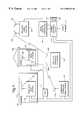
- FIG. 1is a block diagram of a cellular cordless telephone system embodying the present invention
- FIG. 2is a block diagram of a cellular cordless telephone embodying the present invention
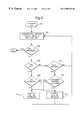
- FIG. 3is a flow diagram showing the operational steps taken under control of the microprocessor to monitor for system availability and connect the CCT to an appropriate system;
- FIG. 4is a flow diagram showing the operational steps taken under control of the microcomputer whilst a call is in progress.
- FIG. 5is a block diagram of a combined DECT/GSM network.
- FIG. 1illustrates a block diagram of a cellular cordless telephone system 100 which embodies the present invention.
- the systemincludes a Public Switched Telephone Network (PSTN) 117 , connected by landlines to cordless base stations 114 , 116 and 118 having respective landline telephone numbers and respectively located in an office building 110 , domestic residence 120 or some other geographical location.
- PSTNPublic Switched Telephone Network
- Cordless base stations 114 , 116 and 118communicate with the cellular cordless telephone (CCT) 200 via antennas 112 , 119 and 122 .
- Antennas 112 , 119 and 122may be implemented as any sort of suitable antenna such as a whip antenna, helical antenna or printed circuit antenna.
- the cordless base stations 114 and 116may be a conventional cordless base station.
- Cordless base station 118is a community cordless base station and such base stations may be located throughout an urban area, or common user area such as a railway station, shopping mall or airport, for providing a shared telephone service to CCTs 200 . In such a case, the cordless base station 118 may include additional equipment not usually found in conventional cordless base stations for billing calls to a telephone number of CCT 200 .
- MSCMobile Switching Centre
- BSCBase Station Controller
- Cellular base station 130comprises both a receive antenna 132 and a transmit antenna 134 for communicating with CCTs 200 .
- the CCT 200may be a mobile unit installed in a vehicle, a so called transportable unit or a hand held portable unit.
- CCT 200comprises an antenna 228 for cordless communication and an antenna 238 for cellular communication.
- the CCT 200may alternatively comprise a single antenna 238 for both cellular and cordless communication and arranged as illustrated in FIG. 2 by the dotted line 272 .
- CT ⁇49 MHz
- CT 2860 MHz
- DECTMHz
- TACS905-915 MHz and 950-960 MHz
- DCS1800 MHz
- FIG. 2illustrates a detailed block diagram of an embodiment of a CCT 200 in accordance with the present invention.
- CCT 200comprises a cellular telephone transceiver 230 , and antenna 238 , a cordless telephone transceiver 220 and antenna 228 , a microprocessor 210 , keypad 201 , display 205 , audio switch 260 , microphone 261 and speaker 262 .
- the microphone 261 , speaker 262 and keypad 201may alternatively be located in a handset separate from the rest of the CCT 200 .
- cordless transceiver 220 and cellular transceiver 230may be coupled to a single antenna 238 by way of band pass filters (BPF) 270 and (BPF) 271 , respectively.
- BPFband pass filters
- Cordless telephone transceiver 220may be any conventional cordless transceiver. However, it would be advantageous if the cordless telephone transceiver 220 conformed to a common air interface for cordless telephones, since this would facilitate roaming of the CCT 200 between different cordless systems. An example of such an interface is the recently introduced common air interface CAI for CT 2 cordless systems.
- the cellular transceiver 230may likewise be any conventional cellular transceiver.
- the keypad 201 , microprocessor 210 , display 205 and the likecan be any available type, connected and arranged to operate in the CCT 200 .
- the microprocessor 210includes a Service Available Register (SAR) 211 for storing which radio systems are currently available to the CCT 200 .
- SARService Available Register
- the microprocessor 210 illustrated in FIG. 2is adapted to operate in accordance with the flow charts illustrated in FIGS. 3-4, for controlling the CCT 200 as a cordless telephone, a cellular telephone or a cellular cordless telephone.
- the CCT 200may operate, as far as a user is concerned, simultaneously as a cellular telephone and a cordless telephone.
- the CCT 200can be so arranged such that both cellular and cordless operations are in progress at the same time.
- cellular and cordless operationscan be performed at different times although this would be done at a speed sufficient for it to be undetectable by the user and therefore appear to be simultaneous operation.
- the microprocessor 210When operating as a cordless telephone control signals from the microprocessor 210 enable cordless receiver 221 and cordless transmitter 222 .
- the microprocessor 210also monitors signals from the cordless receiver 221 indicating received signal strength and for detecting receive data, and from the cordless transmitter 222 for sending transmit data. Additionally, the microprocessor 210 monitors control signals from the cordless transceiver 220 for detecting incoming calls (ringing), security codes and broadcast information relevant to the cordless system, and for sending dialling information.
- the microprocessor 210controls the CCT 200 in a similar way when operating as a cellular telephone, but appropriately modified for the signalling protocols and data encryption used in the cellular system.
- the signalling protocols, data encryption techniques and the like used in respective telephone systemsare well known in the art, and the microprocessor can be arranged to operate in a known manner to effect control of the signals in such systems.
- the audio switch 260is controlled by the microprocessor 210 to link the cordless audio channel 240 or the cellular audio channel 250 to the microphone 261 and loudspeaker 262 as appropriate.
- FIG. 3there is illustrated a flow diagram showing the steps used by microprocessor 210 for operating the CCT 200 to receive and place cellular or cordless telephone calls.
- a cellular serviceis generally available when a cordless service is not, and that a cordless service is the preferred service.
- the useractivates the CCT 200 and the microprocessor 210 monitors both the cellular and cordless system availability. If the cellular and/or cordless system are available the microprocessor 210 updates the display 205 and SAR 211 at step 304 .
- a checkis made to see if a call is in progress or not.
- the YES branch from decision block 306is taken to decision block 308 where it is determined whether or not the incoming call is a cordless call. If so, the YES branch is taken from decision block 308 to block 310 and the incoming call is connected as a cordless call. Additionally, the display 205 can be activated to show that a cordless telephone call is in progress. If the incoming call is not a cordless call, then the NO branch is taken from decision block 308 to block 316 and the call is connected as a cellular call. The display 205 again can be activated, but this time to indicate that a cellular call is in progress.
- the YES branchis taken to decision block 314 to see if the system available register indicates that the cordless system is available. If so, then the YES branch is taken and the call is connected as a cordless call. If not, then the call is connected as a cellular call. Once a call has been connected then the CCT 200 microprocessor 210 returns to block 304 and continues monitoring for cellular and cordless systems.
- the CCT 200continues to monitor for the availability of the cellular and cordless systems.
- a checkis made to see if the cordless system is available. If so, then the YES branch is taken to decision block 328 where it is determined whether the call in progress is a cordless call or not. If it is a cordless call, then the YES branch is taken to block 304 and the CCT 200 continues monitoring for the availability of the cellular and cordless systems. If the call in progress at decision block 328 is not a cordless call then the NO branch is taken to block 330 where handover of the call to the cordless system is initiated.
- the NO branchis taken to decision block 304 where a check is made to see if the cellular system is available. If not, the NO branch is taken and the CCT 200 continues to monitor for cellular and cordless systems. If the cellular system is available then the YES branch is taken from decision block 324 to decision block 325 to check whether the call in progress is a cellular call. If so, then the YES branch is taken to block 304 . If not, then the NO branch is taken to block 326 where handover of the call to the cellular system is initiated. The CCT 200 then continues to monitor the availability of cellular and cordless systems at block 304 .
- the handover of a call from a cordless system to a cellular system and vice versacan be performed manually or preferably automatically. Examples of handover between cellular and cordless systems, and vice versa, are disclosed in co-pending British Patent applications no 9320814.8 and no 9320815.8.
- the criteria for the decision blocks in the flow charts of FIGS. 3 and 4have been correspondingly chosen.
- the criterion, or criteria, at each decision blockmay be far more complex. For example, they may be based on the quality of the signal from the available systems.
- the handover of a call in progresswould typically be preceded by decisions based on the quality of system signals and whether signals from the current system were deteriorating or not. Such criteria would enable a call to be handed over before it was lost due to signal breakdown or the like.
- the criteriamay be based on a user indicated or preprogrammed preference for any particular system, such as a cellular system and not a cordless system as presumed in the foregoing example.
- CCT 200initially receives an incoming call in whatever system the incoming call originated. If the incoming call is from a system which does not fulfil the criteria for the choice of system, then the call may be transferred to the system which does fulfil the aforesaid criteria.
- a systemcould utilise a form of call forwarding as disclosed in U.S. Pat. No. 4,989,230. However, such call forwarding is instructed by CCT 200 and takes place only after the non-preferred part of the CCT 200 has been paged.
- An alternativewould be to have a cellular and cordless system which were interlinked so as to have knowledge of the geographical and/or system location of a particular CCT 200 .
- a call originating in a non-preferred systemwould be automatically redirected by the non-preferred system to the preferred system.
- Such a systemwould also facilitate inter-system handover whilst calls were in progress.
- a radiotelephone suitable for such operationwould be a combined GSM/DECT CCT 200 .
- the cellular base stations 130are connected to Mobile Switching Centres (MSCS) 138 which themselves may be connected to other MSCs, the PSTN 117 (as shown in FIG. 1) comprising the Integrated Services Digital Network (ISDN), or the like.
- the MSC 138is also connected to a Visitor Location Register VLR 137 , which is a data base of GSM subscriber files of GSM subscribers visiting the area of the MSC 138 to which the VLR relates.
- the MSC 138also has a Home Location Register HLR 139 which is a database of all the subscribers having that particular MSC 138 as their home MSC.
- the MSC 138is also connected to other elements of the GSM network such as an Authentication Centre AC and an Equipment Identity Register EIR.
- GSMGlobal System for Mobile communications
- EIREquipment Identity Register
- a cellular telephone or CCT 200 operating in a MSC areacommunicates with the MSC via a base station in order to register its presence in the area assigned to that particular MSC. Such registration may be carried out by a dual system GSM/DECT CCT 200 whilst it monitors the availability of the GSM system.
- the location of a CCT 200 phone within the GSM systemwould be known. Since the MSC 138 is connected to the PSTN 117 , the location of a CCT 200 in the GSM system can also be known to the DECT system since the system is connected to DECT the land line PSTN system.
- DECT phones, in common with CT-2 type phones,are capable of being paged via community base stations as well as domestic base stations.
- a cordless telephonepre-registers with a cordless base station indicating to a network control centre (connected to the PSTN) the location of the cordless telephone.
- a combined GSM/DECT CCT 200may perform the pre-registering during the monitoring for the availability of the GSM and DECT systems.
- both the network control centre and the MSCmay have access to the whereabouts of respective GSM and DECT phone numbers.
- the signalling between the network control centre of the cordless system and the MSCwould need to be very fast, and need to utilise the ISDN of the PSTN.
- FIG. 5An alternative GSM/DECT combined system is shown schematically in FIG. 5 .
- CCFPCentral Control Fixed. Parts
- Each CCFP 505controls a number of cordless base stations., known as Radio Fixed Parts (RFP) 510 in the DECT system, and is connected directly to its local MSC 138 .
- RFPRadio Fixed Parts
- Such direct connections 530may be by land line or preferably by line of sight radio communication.
- the RFPs 510 and CCFP 505may comprise a community DECT system in an airport or the like, or may comprise a private office based DECT system. Access to the PSTN from the DECT system is then via the MSC 138 of the GSM system.
- the MSC 138can also be connected to Base Station Controllers (BSC's) 520 which in turn are connected to and control Base Transceiver stations (BTS) 515 , forming part of the conventional GSM system.
- BSC'sBase Station Controllers
- BTSBase Transceiver stations
- the direct link 530 between the CCFP 505 and MSC 138has an information bandwidth of typically 2 Mbits/s. Such a bandwidth is capable of transmitting the necessary control signals between the MSC 138 and the CCFP 505 to facilitate automatic paging between systems and automatic handover between systems.
- the CCFP 505 of the DECT systemmay have access to the VLR 137 , HLR 139 , AC and EIR of MSC 138 via the direct link 530 .
- each CCFP 505can monitor the whereabouts of other radio telephones and can also use the security checks provided by the GSM system to monitor radio telephones logged onto the DECT system.
- a CCT 200 in accordance with the present invention and operating as a GSM/DECT CCT 200 in either GSM/DECT environment as described above,may register with whichever system fulfils the criteria for operating the CCT 200 in a particular system.
- the CCT 200may register with both systems but preferably operate in only one of them.
- a call originating on any particular systemwill be directed via the MSC, PSTN and network control centre as appropriate to the system on which the paged CCT 200 is registered, or to the system for which the paged CCT 200 has indicated a preference.
- inter system knowledge of the location of CCTs 200will facilitate handover during calls. For example, if a CCT 200 having a call in progress on a non-preferred system enters the service area of a preferred system then the CCT 200 can register with the preferred system, and flag to the system MSC or network control centre that it is a preferred system. Then, the preferred system MSC or network control centre can communicate with the non-preferred system's MSC or network control centre and instruct it to handover the call to the preferred system.
- a multi-system radio telephonecould be operable for more than two radio systems, and not necessarily for a cellular and a cordless system.
- a cellular phonecombined with a satellite communication phone or a micro-cellular (e.g. DCS 1800) and GSM phones.
- a micro-cellular (e.g. DCS 1800) and GSM phonesOther possible combinations could be JDC (PDC)/PHP and CT2/AMPS phones.
Landscapes
- Engineering & Computer Science (AREA)
- Computer Networks & Wireless Communication (AREA)
- Signal Processing (AREA)
- Computer Security & Cryptography (AREA)
- Mobile Radio Communication Systems (AREA)
Abstract
Description
Claims (21)
Priority Applications (1)
| Application Number | Priority Date | Filing Date | Title |
|---|---|---|---|
| US08/746,746US6708028B1 (en) | 1993-12-22 | 1996-11-15 | Multi-mode radio telephone |
Applications Claiming Priority (4)
| Application Number | Priority Date | Filing Date | Title |
|---|---|---|---|
| GB9326189AGB2285555B (en) | 1993-12-22 | 1993-12-22 | Multi-mode radio telephone |
| GB9326189 | 1993-12-22 | ||
| US35991094A | 1994-12-20 | 1994-12-20 | |
| US08/746,746US6708028B1 (en) | 1993-12-22 | 1996-11-15 | Multi-mode radio telephone |
Related Parent Applications (1)
| Application Number | Title | Priority Date | Filing Date |
|---|---|---|---|
| US35991094AContinuation | 1993-12-22 | 1994-12-20 |
Publications (1)
| Publication Number | Publication Date |
|---|---|
| US6708028B1true US6708028B1 (en) | 2004-03-16 |
Family
ID=31948083
Family Applications (1)
| Application Number | Title | Priority Date | Filing Date |
|---|---|---|---|
| US08/746,746Expired - Fee RelatedUS6708028B1 (en) | 1993-12-22 | 1996-11-15 | Multi-mode radio telephone |
Country Status (1)
| Country | Link |
|---|---|
| US (1) | US6708028B1 (en) |
Cited By (47)
| Publication number | Priority date | Publication date | Assignee | Title |
|---|---|---|---|---|
| US20010009845A1 (en)* | 2000-01-24 | 2001-07-26 | Stefan Feuchtinger | Subscriber radiotelephone terminal unit and terminals for such units |
| US20010025526A1 (en)* | 1994-03-04 | 2001-10-04 | Klaus Reymann | Device for measuring the mass of a flowing medium |
| US20020018459A1 (en)* | 2000-05-30 | 2002-02-14 | Alcatel | Method of synchronizing the operation of two or more interfaces |
| US20020147009A1 (en)* | 2001-04-05 | 2002-10-10 | International Business Machines Corporation | Wireless telephone system with both cordless short range communication and long range mobile wireless cellular telephone communication |
| US20020186701A1 (en)* | 1996-10-31 | 2002-12-12 | Kaplan Allen D. | Multi-protocol telecommunications routing optimization |
| US20030092451A1 (en)* | 2001-11-15 | 2003-05-15 | Ibm Corporation | Method of mobile phone consolidation |
| US20030235167A1 (en)* | 2002-06-25 | 2003-12-25 | Stephen Kuffner | Multiple mode RF communication device |
| US20040095945A1 (en)* | 2002-09-09 | 2004-05-20 | Bmd Wireless Ag | Method for integrated communications in a telecommunications network, switching center, integrated communication terminal and telecommunications network |
| US20050054335A1 (en)* | 2003-09-04 | 2005-03-10 | Sbc Knowledge Ventures, L.P. | Call forwarding control device and method of call management |
| US20050064866A1 (en)* | 2001-12-29 | 2005-03-24 | Lenovo (Beijing) Limited | Combined long and short distance wireless communication system and its method |
| US20050064853A1 (en)* | 2003-09-23 | 2005-03-24 | Sbc Knowledge Ventures, L.P. | Unified telephone handset for personal communications based on wireline and wireless network convergence |
| US20050063528A1 (en)* | 2003-09-23 | 2005-03-24 | Sbc Knowledge Ventures, L.P. | Location based call routing for call answering services |
| US20050096024A1 (en)* | 2003-11-05 | 2005-05-05 | Sbc Knowledge Ventures, L.P. | System and method of transitioning between cellular and voice over internet protocol communication |
| US20050153731A1 (en)* | 2004-01-09 | 2005-07-14 | Mckinney John | Communication device and method of operation therefore |
| US20050239496A1 (en)* | 2004-04-14 | 2005-10-27 | Nortel Networks Limited | Mobile terminal with wired and wireless network interfaces |
| US20050286690A1 (en)* | 2004-06-02 | 2005-12-29 | Interdigital Technology Corporation | Method and system for routing calls based on user provided mobile station usage parameters |
| US20060003806A1 (en)* | 2004-07-02 | 2006-01-05 | Sbc Knowledge Ventures, L.P. | Phone synchronization device and method of handling personal information |
| US20060084467A1 (en)* | 2004-10-09 | 2006-04-20 | Lg Electronics Inc. | Apparatus and method for selectively connecting mobile communication terminal to telephone network |
| US20060211405A1 (en)* | 1997-05-21 | 2006-09-21 | Pocketfinder Inc. | Call receiving system apparatus and method having a dedicated switch |
| US20060252423A1 (en)* | 2003-08-05 | 2006-11-09 | Roamware, Inc. | Method and apparatus by which a home network can detect and counteract visited network inbound network traffic redirection |
| EP1725064A1 (en)* | 2005-05-17 | 2006-11-22 | AT&T Corp. | Method and apparatus for routing a call to a dual mode wireless device |
| DE102005027244A1 (en)* | 2005-06-13 | 2006-12-14 | Infineon Technologies Ag | Mobile radio-communication device registration method for e.g. car, involves determining whether registration criterion is fulfilled when device is arranged in supply area, and starting registration procedure when criterion is fulfilled |
| US20070099613A1 (en)* | 2005-10-31 | 2007-05-03 | Motorola, Inc. | Method and system for forwarding calls to a secondary wireless network using a multi-protocol wireless device |
| US20070229350A1 (en)* | 2005-02-01 | 2007-10-04 | Scalisi Joseph F | Apparatus and Method for Providing Location Information on Individuals and Objects using Tracking Devices |
| US20070259660A1 (en)* | 2004-04-01 | 2007-11-08 | Eci Telecom Ltd. | Supporting Mobile Communications Session in a Combined Communications Network |
| US20080051094A1 (en)* | 2006-08-24 | 2008-02-28 | Nokia Corporation | System and method for facilitating communications |
| US20080225832A1 (en)* | 1996-10-31 | 2008-09-18 | Kaplan Allen D | Multi-protocol telecommunications routing optimization |
| US20090103722A1 (en)* | 2007-10-18 | 2009-04-23 | Anderson Roger B | Apparatus and method to provide secure communication over an insecure communication channel for location information using tracking devices |
| US20090111393A1 (en)* | 2007-10-31 | 2009-04-30 | Scalisi Joseph F | Apparatus and Method for Manufacturing an Electronic Package |
| US20090119119A1 (en)* | 2007-11-06 | 2009-05-07 | Scalisi Joseph F | System and method for creating and managing a personalized web interface for monitoring location information on individuals and objects using tracking devices |
| US7551920B1 (en)* | 2003-09-18 | 2009-06-23 | Sprint Spectrum L.P. | Signal strength-based call forwarding for wireless phones |
| US20090163198A1 (en)* | 2007-12-20 | 2009-06-25 | Embarq Holdings Company, Llc | System and method for establishing optimal parameters for performing seamless call transfer between cordless and wireless modes |
| US20090174603A1 (en)* | 2008-01-06 | 2009-07-09 | Scalisi Joseph F | Apparatus and method for determining location and tracking coordinates of a tracking device |
| US7738872B1 (en)* | 1998-12-30 | 2010-06-15 | At&T Intellectual Property Ii, L.P. | Neighborhood cordless service call handoff |
| US20110103354A1 (en)* | 2009-10-29 | 2011-05-05 | Huawei Device Co., Ltd | DECT Base and DECT Terminal |
| US20110103571A1 (en)* | 2005-02-18 | 2011-05-05 | Fabien Astic | Local Area Network System Comprising at Least One Telephone Terminal and Multimedia Terminals |
| US8081072B2 (en) | 2005-02-01 | 2011-12-20 | Location Based Technologies Inc. | Adaptable user interface for monitoring location tracking devices out of GPS monitoring range |
| US8224355B2 (en) | 2007-11-06 | 2012-07-17 | Location Based Technologies Inc. | System and method for improved communication bandwidth utilization when monitoring location information |
| US20130058326A1 (en)* | 2002-05-16 | 2013-03-07 | International Business Machines Corporation | Internet telephony unit and software for enabling internet telephone access from traditional telephone interface |
| US20130137409A1 (en)* | 2003-04-22 | 2013-05-30 | Intellectual Discovery Co., Ltd. | Systems and methods for mobile communications |
| US8497774B2 (en) | 2007-04-05 | 2013-07-30 | Location Based Technologies Inc. | Apparatus and method for adjusting refresh rate of location coordinates of a tracking device |
| EP2663129A1 (en)* | 2012-05-11 | 2013-11-13 | Uros Oy | Selection procedure of wireless network |
| US8774827B2 (en) | 2007-04-05 | 2014-07-08 | Location Based Technologies, Inc. | Apparatus and method for generating position fix of a tracking device in accordance with a subscriber service usage profile to conserve tracking device power |
| US9042371B1 (en) | 2003-04-10 | 2015-05-26 | Rpx Clearinghouse Llc | Integrating telephone lines with packet connections |
| US20160323795A1 (en)* | 2012-01-10 | 2016-11-03 | John Braun | Message injection system and method |
| US20170099097A1 (en)* | 2013-02-11 | 2017-04-06 | Gogo Llc | Multiple antenna system and method for mobile platforms |
| US9730146B2 (en) | 2002-02-26 | 2017-08-08 | Lincoln J. Unruh | System and method for reliable communications over multiple packet RF networks |
Citations (22)
| Publication number | Priority date | Publication date | Assignee | Title |
|---|---|---|---|---|
| GB2225512A (en) | 1988-09-23 | 1990-05-30 | Motorola Inc | Cellular cordless telephone |
| EP0415502A2 (en) | 1989-09-01 | 1991-03-06 | Philips Electronics Uk Limited | Communications system |
| GB2240696A (en) | 1990-01-31 | 1991-08-07 | Nec Corp | Method of controlling handoff in cellular mobile radio communications systems |
| GB2242805A (en) | 1990-04-06 | 1991-10-09 | Stc Plc | Handover techniques in cellular radio |
| WO1992003006A1 (en) | 1990-08-03 | 1992-02-20 | Motorola, Inc. | Two way cordless telephone communication system |
| US5127042A (en)* | 1988-09-23 | 1992-06-30 | Motorola, Inc. | Cellular cordless telephone |
| WO1992012602A1 (en) | 1990-12-27 | 1992-07-23 | British Telecommunications Public Limited Company | Mobile radio handover initiation determination |
| GB2252699A (en) | 1990-11-29 | 1992-08-12 | Matsushita Electric Industrial Co Ltd | Mobile communication system |
| US5159593A (en)* | 1990-07-02 | 1992-10-27 | Motorola, Inc. | Channel acquistion and handoff method and apparatus for a TDMA communication system |
| US5235632A (en)* | 1990-04-10 | 1993-08-10 | Telefonaktiebolaget L M Ericsson | Mobile telephony system intended for indoor and outdoor subscriber use |
| WO1993016560A1 (en)* | 1992-02-06 | 1993-08-19 | Motorola, Inc. | Dual system cellular cordless radiotelephone apparatus and method |
| US5278991A (en)* | 1990-04-06 | 1994-01-11 | Stc Plc | Handover techniques |
| GB2269723A (en) | 1992-07-17 | 1994-02-16 | Sagem | Mobile radiotelephony combining cellular and local cordless systems |
| JPH06252837A (en) | 1993-02-23 | 1994-09-09 | Matsushita Electric Ind Co Ltd | Radio telephone equipment |
| US5367558A (en)* | 1988-09-23 | 1994-11-22 | Motorola, Inc. | Cellular cordless telephone |
| US5384824A (en)* | 1991-07-02 | 1995-01-24 | Nokia Telecommunications Oy | Method for carrying out a location updating from a mobile cellular radiophone system to another cellular radiophone system |
| GB2282731A (en) | 1993-10-08 | 1995-04-12 | Nokia Telecommunications Oy | Dual mode subscriber terminal and a handover procedure of the dual mode subscriber terminal in a mobile telecommunications network |
| GB2282730A (en) | 1993-10-08 | 1995-04-12 | Nokia Telecommunications Oy | Handover procedure in a dual-mode telecommunication network |
| GB2284725A (en) | 1993-11-27 | 1995-06-14 | Motorola Ltd | Method for determining handoff |
| GB2285198A (en) | 1993-12-22 | 1995-06-28 | Nokia Mobile Phones Ltd | Multi-mode radio telephone |
| US5442680A (en)* | 1992-06-23 | 1995-08-15 | Motorola, Inc. | Dual system cellular cordless radiotelephone apparatus with sub-data channel timing monitor |
| US5533099A (en)* | 1994-03-22 | 1996-07-02 | Nokia Mobile Phones Ltd. | Multi-mode radio telephone |
- 1996
- 1996-11-15USUS08/746,746patent/US6708028B1/ennot_activeExpired - Fee Related
Patent Citations (26)
| Publication number | Priority date | Publication date | Assignee | Title |
|---|---|---|---|---|
| US5127042A (en)* | 1988-09-23 | 1992-06-30 | Motorola, Inc. | Cellular cordless telephone |
| US4989230A (en)* | 1988-09-23 | 1991-01-29 | Motorola, Inc. | Cellular cordless telephone |
| US5367558A (en)* | 1988-09-23 | 1994-11-22 | Motorola, Inc. | Cellular cordless telephone |
| GB2225512A (en) | 1988-09-23 | 1990-05-30 | Motorola Inc | Cellular cordless telephone |
| US5463674A (en)* | 1988-09-23 | 1995-10-31 | Motorola, Inc. | Cellular cordless telephone which polls information in a memory to determine a pre-selected preference and a stored availability of call forwarding |
| EP0415502A2 (en) | 1989-09-01 | 1991-03-06 | Philips Electronics Uk Limited | Communications system |
| GB2240696A (en) | 1990-01-31 | 1991-08-07 | Nec Corp | Method of controlling handoff in cellular mobile radio communications systems |
| GB2242805A (en) | 1990-04-06 | 1991-10-09 | Stc Plc | Handover techniques in cellular radio |
| US5278991A (en)* | 1990-04-06 | 1994-01-11 | Stc Plc | Handover techniques |
| US5235632A (en)* | 1990-04-10 | 1993-08-10 | Telefonaktiebolaget L M Ericsson | Mobile telephony system intended for indoor and outdoor subscriber use |
| US5159593A (en)* | 1990-07-02 | 1992-10-27 | Motorola, Inc. | Channel acquistion and handoff method and apparatus for a TDMA communication system |
| WO1992003006A1 (en) | 1990-08-03 | 1992-02-20 | Motorola, Inc. | Two way cordless telephone communication system |
| GB2252699A (en) | 1990-11-29 | 1992-08-12 | Matsushita Electric Industrial Co Ltd | Mobile communication system |
| WO1992012602A1 (en) | 1990-12-27 | 1992-07-23 | British Telecommunications Public Limited Company | Mobile radio handover initiation determination |
| US5384824A (en)* | 1991-07-02 | 1995-01-24 | Nokia Telecommunications Oy | Method for carrying out a location updating from a mobile cellular radiophone system to another cellular radiophone system |
| FR2687874A1 (en) | 1992-02-06 | 1993-08-27 | Motorola Inc | RADIOTELEPHONE APPARATUS OPERATING IN A DUAL, CORDLESS AND CELLULAR SYSTEM, AND ITS OPERATING METHOD. |
| WO1993016560A1 (en)* | 1992-02-06 | 1993-08-19 | Motorola, Inc. | Dual system cellular cordless radiotelephone apparatus and method |
| US5442680A (en)* | 1992-06-23 | 1995-08-15 | Motorola, Inc. | Dual system cellular cordless radiotelephone apparatus with sub-data channel timing monitor |
| GB2269723A (en) | 1992-07-17 | 1994-02-16 | Sagem | Mobile radiotelephony combining cellular and local cordless systems |
| JPH06252837A (en) | 1993-02-23 | 1994-09-09 | Matsushita Electric Ind Co Ltd | Radio telephone equipment |
| GB2282731A (en) | 1993-10-08 | 1995-04-12 | Nokia Telecommunications Oy | Dual mode subscriber terminal and a handover procedure of the dual mode subscriber terminal in a mobile telecommunications network |
| GB2282730A (en) | 1993-10-08 | 1995-04-12 | Nokia Telecommunications Oy | Handover procedure in a dual-mode telecommunication network |
| US5659598A (en)* | 1993-10-08 | 1997-08-19 | Nokia Telecommunications Oy | Dual mode subscriber terminal and a handover procedure of the dual mode subscriber terminal in a mobile telecommunication network |
| GB2284725A (en) | 1993-11-27 | 1995-06-14 | Motorola Ltd | Method for determining handoff |
| GB2285198A (en) | 1993-12-22 | 1995-06-28 | Nokia Mobile Phones Ltd | Multi-mode radio telephone |
| US5533099A (en)* | 1994-03-22 | 1996-07-02 | Nokia Mobile Phones Ltd. | Multi-mode radio telephone |
Non-Patent Citations (3)
| Title |
|---|
| "Provision of Mobility for DECT by Interworking with GSM" by Lundstrom, EPOC and N '93, Eleventh Annual Conference, The Hage, pp 97-99, 1993. |
| "The Universal Mobile Telecommunication System", by Chia, IEEE Communication Magazine, vol. 30, No. 12, Dec. 1992, pp. 54-62. |
| Japanese Abstract Dialog Accession No. 04175818 of Japanese Publication No.: JP 5167518 A (Matsushita), Jul. 2, 1993, one page. |
Cited By (82)
| Publication number | Priority date | Publication date | Assignee | Title |
|---|---|---|---|---|
| US20010025526A1 (en)* | 1994-03-04 | 2001-10-04 | Klaus Reymann | Device for measuring the mass of a flowing medium |
| US20020186701A1 (en)* | 1996-10-31 | 2002-12-12 | Kaplan Allen D. | Multi-protocol telecommunications routing optimization |
| US20080225832A1 (en)* | 1996-10-31 | 2008-09-18 | Kaplan Allen D | Multi-protocol telecommunications routing optimization |
| US20070232351A1 (en)* | 1997-05-21 | 2007-10-04 | Scalisi Joseph F | Communication system and method including dual mode capability |
| US20060211405A1 (en)* | 1997-05-21 | 2006-09-21 | Pocketfinder Inc. | Call receiving system apparatus and method having a dedicated switch |
| US20080090550A1 (en)* | 1997-05-21 | 2008-04-17 | Pocketfinder Inc. | Communication system and method including communication billing options |
| US8098132B2 (en) | 1997-05-21 | 2012-01-17 | Location Based Technologies Inc. | Call receiving system and apparatus for selective reception of caller communication |
| US7738872B1 (en)* | 1998-12-30 | 2010-06-15 | At&T Intellectual Property Ii, L.P. | Neighborhood cordless service call handoff |
| US7805141B1 (en)* | 1998-12-30 | 2010-09-28 | At&T Intellectual Property Ii, L.P. | Neighborhood cordless service call handoff |
| US20010009845A1 (en)* | 2000-01-24 | 2001-07-26 | Stefan Feuchtinger | Subscriber radiotelephone terminal unit and terminals for such units |
| US7376416B2 (en)* | 2000-01-24 | 2008-05-20 | Alcatel | Subscriber radiotelephone terminal unit and terminals for such units |
| US20020018459A1 (en)* | 2000-05-30 | 2002-02-14 | Alcatel | Method of synchronizing the operation of two or more interfaces |
| US7095728B2 (en)* | 2000-05-30 | 2006-08-22 | Alcatel | Synchronized contention resolution and burst timing allocation in the operation of two or more interfaces |
| US20020147009A1 (en)* | 2001-04-05 | 2002-10-10 | International Business Machines Corporation | Wireless telephone system with both cordless short range communication and long range mobile wireless cellular telephone communication |
| US20030092451A1 (en)* | 2001-11-15 | 2003-05-15 | Ibm Corporation | Method of mobile phone consolidation |
| US20050064866A1 (en)* | 2001-12-29 | 2005-03-24 | Lenovo (Beijing) Limited | Combined long and short distance wireless communication system and its method |
| US9743340B2 (en) | 2002-02-26 | 2017-08-22 | Lincoln J Unruh | System and method for reliable communications over multiple packet RF networks |
| US9730146B2 (en) | 2002-02-26 | 2017-08-08 | Lincoln J. Unruh | System and method for reliable communications over multiple packet RF networks |
| US20130058326A1 (en)* | 2002-05-16 | 2013-03-07 | International Business Machines Corporation | Internet telephony unit and software for enabling internet telephone access from traditional telephone interface |
| US9112953B2 (en)* | 2002-05-16 | 2015-08-18 | International Business Machines Corporation | Internet telephony unit and software for enabling internet telephone access from traditional telephone interface |
| US6954446B2 (en)* | 2002-06-25 | 2005-10-11 | Motorola, Inc. | Multiple mode RF communication device |
| US20030235167A1 (en)* | 2002-06-25 | 2003-12-25 | Stephen Kuffner | Multiple mode RF communication device |
| US20040095945A1 (en)* | 2002-09-09 | 2004-05-20 | Bmd Wireless Ag | Method for integrated communications in a telecommunications network, switching center, integrated communication terminal and telecommunications network |
| US9042371B1 (en) | 2003-04-10 | 2015-05-26 | Rpx Clearinghouse Llc | Integrating telephone lines with packet connections |
| US8897761B2 (en)* | 2003-04-22 | 2014-11-25 | Intellectual Discovery Co., Ltd. | Systems and methods for mobile communications |
| US20130137409A1 (en)* | 2003-04-22 | 2013-05-30 | Intellectual Discovery Co., Ltd. | Systems and methods for mobile communications |
| US20060252423A1 (en)* | 2003-08-05 | 2006-11-09 | Roamware, Inc. | Method and apparatus by which a home network can detect and counteract visited network inbound network traffic redirection |
| US7616950B2 (en) | 2003-09-04 | 2009-11-10 | At&T Intellectual Property I, L.P. | Call forwarding control device and method of call management |
| US20050054335A1 (en)* | 2003-09-04 | 2005-03-10 | Sbc Knowledge Ventures, L.P. | Call forwarding control device and method of call management |
| US7551920B1 (en)* | 2003-09-18 | 2009-06-23 | Sprint Spectrum L.P. | Signal strength-based call forwarding for wireless phones |
| US20050064853A1 (en)* | 2003-09-23 | 2005-03-24 | Sbc Knowledge Ventures, L.P. | Unified telephone handset for personal communications based on wireline and wireless network convergence |
| US20050063528A1 (en)* | 2003-09-23 | 2005-03-24 | Sbc Knowledge Ventures, L.P. | Location based call routing for call answering services |
| US7885657B2 (en) | 2003-11-05 | 2011-02-08 | At&T Intellectual Property I, L.P. | System and method of transitioning between cellular and voice over internet protocol communication |
| US20050096024A1 (en)* | 2003-11-05 | 2005-05-05 | Sbc Knowledge Ventures, L.P. | System and method of transitioning between cellular and voice over internet protocol communication |
| US7577427B2 (en) | 2003-11-05 | 2009-08-18 | At&T Intellectual Property I, L.P. | System and method of transitioning between cellular and voice over internet protocol communication |
| US20090238147A1 (en)* | 2003-11-05 | 2009-09-24 | At&T Intellectual Property I, L.P. | System and Method of Transitioning Between Cellular and Voice Over Internet Protocol Communication |
| US20050153731A1 (en)* | 2004-01-09 | 2005-07-14 | Mckinney John | Communication device and method of operation therefore |
| US7113804B2 (en)* | 2004-01-09 | 2006-09-26 | Motorola, Inc. | Communication device and method of operation therefore |
| US7761094B2 (en)* | 2004-04-01 | 2010-07-20 | Eci Telecom Ltd. | Supporting mobile communications session in a combined communications network |
| US20070259660A1 (en)* | 2004-04-01 | 2007-11-08 | Eci Telecom Ltd. | Supporting Mobile Communications Session in a Combined Communications Network |
| US20050239496A1 (en)* | 2004-04-14 | 2005-10-27 | Nortel Networks Limited | Mobile terminal with wired and wireless network interfaces |
| US20050286690A1 (en)* | 2004-06-02 | 2005-12-29 | Interdigital Technology Corporation | Method and system for routing calls based on user provided mobile station usage parameters |
| US7376411B2 (en)* | 2004-06-02 | 2008-05-20 | Interdigital Technology Corporation | Method and system for routing calls as determined by a call cost database of a wireless transmit/receive unit |
| US20060003806A1 (en)* | 2004-07-02 | 2006-01-05 | Sbc Knowledge Ventures, L.P. | Phone synchronization device and method of handling personal information |
| US7801557B2 (en)* | 2004-10-09 | 2010-09-21 | Lg Electronics Inc. | Apparatus and method for selectively connecting mobile communication terminal to telephone network |
| US20060084467A1 (en)* | 2004-10-09 | 2006-04-20 | Lg Electronics Inc. | Apparatus and method for selectively connecting mobile communication terminal to telephone network |
| US8531289B2 (en) | 2005-02-01 | 2013-09-10 | Location Based Technologies Inc. | Adaptable user interface for monitoring location tracking devices out of GPS monitoring range |
| US20070229350A1 (en)* | 2005-02-01 | 2007-10-04 | Scalisi Joseph F | Apparatus and Method for Providing Location Information on Individuals and Objects using Tracking Devices |
| US8081072B2 (en) | 2005-02-01 | 2011-12-20 | Location Based Technologies Inc. | Adaptable user interface for monitoring location tracking devices out of GPS monitoring range |
| US20110103571A1 (en)* | 2005-02-18 | 2011-05-05 | Fabien Astic | Local Area Network System Comprising at Least One Telephone Terminal and Multimedia Terminals |
| EP1725064A1 (en)* | 2005-05-17 | 2006-11-22 | AT&T Corp. | Method and apparatus for routing a call to a dual mode wireless device |
| US8599873B2 (en) | 2005-05-17 | 2013-12-03 | At&T Intellectual Property Ii, L.P. | Method and apparatus for routing a call to a dual mode wireless device |
| US20060268928A1 (en)* | 2005-05-17 | 2006-11-30 | Farhad Barzegar | Method and apparatus for routing a call to a dual mode wireless device |
| US7742498B2 (en)* | 2005-05-17 | 2010-06-22 | At&T Intellectual Property Ii, L.P. | Method and apparatus for routing a call to a dual mode wireless device |
| DE102005027244A1 (en)* | 2005-06-13 | 2006-12-14 | Infineon Technologies Ag | Mobile radio-communication device registration method for e.g. car, involves determining whether registration criterion is fulfilled when device is arranged in supply area, and starting registration procedure when criterion is fulfilled |
| US20070099613A1 (en)* | 2005-10-31 | 2007-05-03 | Motorola, Inc. | Method and system for forwarding calls to a secondary wireless network using a multi-protocol wireless device |
| US20080051094A1 (en)* | 2006-08-24 | 2008-02-28 | Nokia Corporation | System and method for facilitating communications |
| US8774827B2 (en) | 2007-04-05 | 2014-07-08 | Location Based Technologies, Inc. | Apparatus and method for generating position fix of a tracking device in accordance with a subscriber service usage profile to conserve tracking device power |
| US8497774B2 (en) | 2007-04-05 | 2013-07-30 | Location Based Technologies Inc. | Apparatus and method for adjusting refresh rate of location coordinates of a tracking device |
| US8654974B2 (en) | 2007-10-18 | 2014-02-18 | Location Based Technologies, Inc. | Apparatus and method to provide secure communication over an insecure communication channel for location information using tracking devices |
| US20090103722A1 (en)* | 2007-10-18 | 2009-04-23 | Anderson Roger B | Apparatus and method to provide secure communication over an insecure communication channel for location information using tracking devices |
| US9111189B2 (en) | 2007-10-31 | 2015-08-18 | Location Based Technologies, Inc. | Apparatus and method for manufacturing an electronic package |
| US20090111393A1 (en)* | 2007-10-31 | 2009-04-30 | Scalisi Joseph F | Apparatus and Method for Manufacturing an Electronic Package |
| US20090119119A1 (en)* | 2007-11-06 | 2009-05-07 | Scalisi Joseph F | System and method for creating and managing a personalized web interface for monitoring location information on individuals and objects using tracking devices |
| US8244468B2 (en) | 2007-11-06 | 2012-08-14 | Location Based Technology Inc. | System and method for creating and managing a personalized web interface for monitoring location information on individuals and objects using tracking devices |
| US8224355B2 (en) | 2007-11-06 | 2012-07-17 | Location Based Technologies Inc. | System and method for improved communication bandwidth utilization when monitoring location information |
| US20090163198A1 (en)* | 2007-12-20 | 2009-06-25 | Embarq Holdings Company, Llc | System and method for establishing optimal parameters for performing seamless call transfer between cordless and wireless modes |
| US8295827B2 (en)* | 2007-12-20 | 2012-10-23 | Centurylink Intellectual Property Llc | System and method for establishing optimal parameters for performing seamless call transfer between cordless and wireless modes |
| US20090174603A1 (en)* | 2008-01-06 | 2009-07-09 | Scalisi Joseph F | Apparatus and method for determining location and tracking coordinates of a tracking device |
| US8421619B2 (en) | 2008-01-06 | 2013-04-16 | Location Based Technologies, Inc. | Apparatus and method for determining location and tracking coordinates of a tracking device |
| US8421618B2 (en) | 2008-01-06 | 2013-04-16 | Location Based Technologies, Inc. | Apparatus and method for determining location and tracking coordinates of a tracking device |
| US8542113B2 (en) | 2008-01-06 | 2013-09-24 | Location Based Technologies Inc. | Apparatus and method for determining location and tracking coordinates of a tracking device |
| US8102256B2 (en) | 2008-01-06 | 2012-01-24 | Location Based Technologies Inc. | Apparatus and method for determining location and tracking coordinates of a tracking device |
| US20110103354A1 (en)* | 2009-10-29 | 2011-05-05 | Huawei Device Co., Ltd | DECT Base and DECT Terminal |
| US20160323795A1 (en)* | 2012-01-10 | 2016-11-03 | John Braun | Message injection system and method |
| EP2663129A1 (en)* | 2012-05-11 | 2013-11-13 | Uros Oy | Selection procedure of wireless network |
| US20170099097A1 (en)* | 2013-02-11 | 2017-04-06 | Gogo Llc | Multiple antenna system and method for mobile platforms |
| CN109787680A (en)* | 2013-02-11 | 2019-05-21 | Gogo有限责任公司 | Multiaerial system and method for mobile platform |
| US10680315B2 (en)* | 2013-02-11 | 2020-06-09 | Gogo Llc | Multiple antenna system and method for mobile platforms |
| US11075448B2 (en) | 2013-02-11 | 2021-07-27 | Gogo Business Aviation Llc | Multiple antenna system and method for mobile platforms |
| US11545737B2 (en) | 2013-02-11 | 2023-01-03 | Gogo Business Aviation Llc | Multiple antenna system and method for mobile platforms |
| US12183967B2 (en) | 2013-02-11 | 2024-12-31 | Gogo Business Aviation Llc | Mobile communicator and method of communicating data with a mobile communicator |
Similar Documents
| Publication | Publication Date | Title |
|---|---|---|
| US6708028B1 (en) | Multi-mode radio telephone | |
| EP0660626B1 (en) | Handover between different radio telephone systems | |
| US5737703A (en) | Multi-mode radio telephone which executes handover between different system | |
| US5809419A (en) | Method for reducing channel scanning time | |
| JP3995105B2 (en) | Mobile communication network | |
| EP0660627B1 (en) | Multi-mode radio telephone | |
| CN105744578B (en) | Handover from unrestricted global access point back to restricted local access point in wireless network | |
| US5384824A (en) | Method for carrying out a location updating from a mobile cellular radiophone system to another cellular radiophone system | |
| US5613208A (en) | Channel scan in cellular telephone system | |
| MXPA95005307A (en) | Method for the exploration of ca | |
| EP0700227A2 (en) | Multi-mode radio telephone | |
| JP2002525938A (en) | Improved method and apparatus for replacing cells | |
| JP2000092541A (en) | Wireless communication system, base station device, and wireless portable device | |
| EP1209941A2 (en) | Improved cell handover | |
| US7551934B2 (en) | Cell selection in a communications system | |
| US7136641B2 (en) | Alternative network selection for a communication device | |
| JP2003513536A (en) | System and method for selecting voice service options | |
| JP2003102059A (en) | Access control method for mobile communication system | |
| EP1142422A1 (en) | Configurable communication system having ip-based capabilities | |
| JPH0638266A (en) | Channel changeover information system |
Legal Events
| Date | Code | Title | Description |
|---|---|---|---|
| AS | Assignment | Owner name:NOKIA CORPORATION, FINLAND Free format text:MERGER;ASSIGNOR:NOKIA MOBILE PHONES LTD.;REEL/FRAME:019131/0822 Effective date:20011001 | |
| FPAY | Fee payment | Year of fee payment:4 | |
| FEPP | Fee payment procedure | Free format text:PAYOR NUMBER ASSIGNED (ORIGINAL EVENT CODE: ASPN); ENTITY STATUS OF PATENT OWNER: LARGE ENTITY | |
| AS | Assignment | Owner name:NOKIA MOBILE PHONES LIMITED, FINLAND Free format text:ASSIGNMENT OF ASSIGNORS INTEREST;ASSIGNOR:BYRNE, JOHN DANIEL;REEL/FRAME:026128/0224 Effective date:19941104 | |
| FPAY | Fee payment | Year of fee payment:8 | |
| AS | Assignment | Owner name:MICROSOFT CORPORATION, WASHINGTON Free format text:SHORT FORM PATENT SECURITY AGREEMENT;ASSIGNOR:CORE WIRELESS LICENSING S.A.R.L.;REEL/FRAME:026894/0665 Effective date:20110901 Owner name:NOKIA CORPORATION, FINLAND Free format text:SHORT FORM PATENT SECURITY AGREEMENT;ASSIGNOR:CORE WIRELESS LICENSING S.A.R.L.;REEL/FRAME:026894/0665 Effective date:20110901 | |
| AS | Assignment | Owner name:NOKIA 2011 PATENT TRUST, DELAWARE Free format text:ASSIGNMENT OF ASSIGNORS INTEREST;ASSIGNOR:NOKIA CORPORATION;REEL/FRAME:027120/0608 Effective date:20110531 Owner name:2011 INTELLECTUAL PROPERTY ASSET TRUST, DELAWARE Free format text:CHANGE OF NAME;ASSIGNOR:NOKIA 2011 PATENT TRUST;REEL/FRAME:027121/0353 Effective date:20110901 | |
| AS | Assignment | Owner name:CORE WIRELESS LICENSING S.A.R.L., LUXEMBOURG Free format text:ASSIGNMENT OF ASSIGNORS INTEREST;ASSIGNOR:2011 INTELLECTUAL PROPERTY ASSET TRUST;REEL/FRAME:027392/0239 Effective date:20110831 | |
| REMI | Maintenance fee reminder mailed | ||
| LAPS | Lapse for failure to pay maintenance fees | ||
| STCH | Information on status: patent discontinuation | Free format text:PATENT EXPIRED DUE TO NONPAYMENT OF MAINTENANCE FEES UNDER 37 CFR 1.362 | |
| FP | Lapsed due to failure to pay maintenance fee | Effective date:20160316 | |
| AS | Assignment | Owner name:MICROSOFT CORPORATION, WASHINGTON Free format text:UCC FINANCING STATEMENT AMENDMENT - DELETION OF SECURED PARTY;ASSIGNOR:NOKIA CORPORATION;REEL/FRAME:039872/0112 Effective date:20150327 |