US6707867B2 - Wireless local area network apparatus - Google Patents
Wireless local area network apparatusDownload PDFInfo
- Publication number
- US6707867B2 US6707867B2US10/092,295US9229502AUS6707867B2US 6707867 B2US6707867 B2US 6707867B2US 9229502 AUS9229502 AUS 9229502AUS 6707867 B2US6707867 B2US 6707867B2
- Authority
- US
- United States
- Prior art keywords
- receiver
- timestamp
- transmitter
- transmission signal
- timer
- Prior art date
- Legal status (The legal status is an assumption and is not a legal conclusion. Google has not performed a legal analysis and makes no representation as to the accuracy of the status listed.)
- Expired - Fee Related, expires
Links
- 230000000737periodic effectEffects0.000claimsabstractdescription9
- 230000005540biological transmissionEffects0.000claimsdescription112
- 238000000034methodMethods0.000claimsdescription52
- 230000001934delayEffects0.000claimsdescription16
- 230000008569processEffects0.000claimsdescription15
- 230000008859changeEffects0.000claimsdescription4
- 230000002618waking effectEffects0.000claimsdescription4
- 230000001360synchronised effectEffects0.000abstractdescription8
- 238000004891communicationMethods0.000description9
- 238000010586diagramMethods0.000description6
- 101100172132Mus musculus Eif3a geneProteins0.000description5
- 239000013078crystalSubstances0.000description3
- 230000009467reductionEffects0.000description3
- 238000012549trainingMethods0.000description3
- 230000008901benefitEffects0.000description2
- 125000004122cyclic groupChemical group0.000description2
- 230000000694effectsEffects0.000description2
- 238000012986modificationMethods0.000description2
- 230000004048modificationEffects0.000description2
- 235000008694Humulus lupulusNutrition0.000description1
- 230000001447compensatory effectEffects0.000description1
- 230000003111delayed effectEffects0.000description1
- 230000010354integrationEffects0.000description1
- 238000012545processingMethods0.000description1
- 230000001960triggered effectEffects0.000description1
Images


Classifications
- H—ELECTRICITY
- H04—ELECTRIC COMMUNICATION TECHNIQUE
- H04W—WIRELESS COMMUNICATION NETWORKS
- H04W52/00—Power management, e.g. Transmission Power Control [TPC] or power classes
- H04W52/02—Power saving arrangements
- H04W52/0209—Power saving arrangements in terminal devices
- H04W52/0212—Power saving arrangements in terminal devices managed by the network, e.g. network or access point is leader and terminal is follower
- H04W52/0216—Power saving arrangements in terminal devices managed by the network, e.g. network or access point is leader and terminal is follower using a pre-established activity schedule, e.g. traffic indication frame
- H—ELECTRICITY
- H04—ELECTRIC COMMUNICATION TECHNIQUE
- H04L—TRANSMISSION OF DIGITAL INFORMATION, e.g. TELEGRAPHIC COMMUNICATION
- H04L27/00—Modulated-carrier systems
- H04L27/02—Amplitude-modulated carrier systems, e.g. using on-off keying; Single sideband or vestigial sideband modulation
- H04L27/04—Modulator circuits; Transmitter circuits
- H—ELECTRICITY
- H04—ELECTRIC COMMUNICATION TECHNIQUE
- H04L—TRANSMISSION OF DIGITAL INFORMATION, e.g. TELEGRAPHIC COMMUNICATION
- H04L7/00—Arrangements for synchronising receiver with transmitter
- H04L7/04—Speed or phase control by synchronisation signals
- H—ELECTRICITY
- H04—ELECTRIC COMMUNICATION TECHNIQUE
- H04W—WIRELESS COMMUNICATION NETWORKS
- H04W56/00—Synchronisation arrangements
- H04W56/0055—Synchronisation arrangements determining timing error of reception due to propagation delay
- H04W56/0065—Synchronisation arrangements determining timing error of reception due to propagation delay using measurement of signal travel time
- H04W56/009—Closed loop measurements
- H—ELECTRICITY
- H04—ELECTRIC COMMUNICATION TECHNIQUE
- H04W—WIRELESS COMMUNICATION NETWORKS
- H04W76/00—Connection management
- H04W76/20—Manipulation of established connections
- H04W76/27—Transitions between radio resource control [RRC] states
- H—ELECTRICITY
- H04—ELECTRIC COMMUNICATION TECHNIQUE
- H04W—WIRELESS COMMUNICATION NETWORKS
- H04W84/00—Network topologies
- H04W84/02—Hierarchically pre-organised networks, e.g. paging networks, cellular networks, WLAN [Wireless Local Area Network] or WLL [Wireless Local Loop]
- H04W84/10—Small scale networks; Flat hierarchical networks
- H04W84/12—WLAN [Wireless Local Area Networks]
- H—ELECTRICITY
- H04—ELECTRIC COMMUNICATION TECHNIQUE
- H04W—WIRELESS COMMUNICATION NETWORKS
- H04W88/00—Devices specially adapted for wireless communication networks, e.g. terminals, base stations or access point devices
- H04W88/02—Terminal devices
- H—ELECTRICITY
- H04—ELECTRIC COMMUNICATION TECHNIQUE
- H04W—WIRELESS COMMUNICATION NETWORKS
- H04W88/00—Devices specially adapted for wireless communication networks, e.g. terminals, base stations or access point devices
- H04W88/02—Terminal devices
- H04W88/022—Selective call receivers
- Y—GENERAL TAGGING OF NEW TECHNOLOGICAL DEVELOPMENTS; GENERAL TAGGING OF CROSS-SECTIONAL TECHNOLOGIES SPANNING OVER SEVERAL SECTIONS OF THE IPC; TECHNICAL SUBJECTS COVERED BY FORMER USPC CROSS-REFERENCE ART COLLECTIONS [XRACs] AND DIGESTS
- Y02—TECHNOLOGIES OR APPLICATIONS FOR MITIGATION OR ADAPTATION AGAINST CLIMATE CHANGE
- Y02D—CLIMATE CHANGE MITIGATION TECHNOLOGIES IN INFORMATION AND COMMUNICATION TECHNOLOGIES [ICT], I.E. INFORMATION AND COMMUNICATION TECHNOLOGIES AIMING AT THE REDUCTION OF THEIR OWN ENERGY USE
- Y02D30/00—Reducing energy consumption in communication networks
- Y02D30/70—Reducing energy consumption in communication networks in wireless communication networks
Definitions
- the present inventionrelates to wireless local area network apparatus.
- a wireless local area networkcommonly comprises a plurality of communication stations located in a Basic Service Area (BSA).
- the stationscan send and receive communication signals via a base station and, in this manner, the base station receives the signals from a station in the BSA and re-transmits the signals to the intended recipient station.
- BSABasic Service Area
- the BSAcan be provided as one of a plurality of BSAs which together form an Extended Service Area.
- the base station of each BSAmay comprise an access point for a backbone infrastructure for connecting the BSAs for allowing communication between stations in different BSAs within the Extended Service Area.
- wireless local area network apparatuscomprising transmitter means and receiver means, characterized in that said transmitter means includes transmitter timer means for controlling periodic generation of transmission signals, said receiver means includes receiver timer means, and said transmitter means has means for including transmitter timer data in said signals for synchronizing said receiver timer means with said transmitter timer means, said transmitter timer data representing the state of said transmitter timer means at the time of transmission of the signal in which it is included.
- the wireless local area network apparatus of the present inventionis particularly advantageous for power management applications in which low power portable wireless stations are employed in the BSA.
- the stationsperiodically switch between a low power consumption state, in which their transceivers are de-energized, and a high power consumption state, in which their transceivers are energized, and can thereby receive periodic signals transmitted from some other station.
- the synchronization between the signals transmitted from some other station and the switching of the power-consumption state of the receiver stationsis advantageously achieved by the apparatus of the present invention.
- the improved synchronization of the present inventionallows for operation of the stations in a wireless local area network with reduced power-consumption, which is particularly important for stations having an on-board power supply.
- the apparatus of the present inventioncan be advantageously employed to control other timing relationships between a transmitter and a receiver in a wireless local area network.
- a transmitterfor example, in so-called frequency-hopping devices, the transmission frequency employed by a transmitter is periodically changed and so a receiver has to adapt to this change in communication-signal frequency.
- the apparatus of the present inventionallows for accurate synchronization between the operational changes in the transmitter and receiver during such frequency hopping.
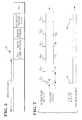
- FIG. 1shows a wireless local area network which forms part of an extended service area
- FIG. 2is a block diagram of a transmitter for use in apparatus embodying the present invention
- FIG. 3shows the structure of a Traffic Indication Message constructed in the transmitter of FIG. 2;
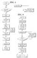
- FIG. 4is a flow diagram of the operation of the transmitter of FIG. 2;
- FIG. 5is a block diagram of a receiver for use in apparatus embodying the present invention.
- FIG. 6is a flow diagram of the operation of the receiver of FIG. 5.
- FIG. 7is a timing diagram illustrating operation of the transmitter of FIG. 2 and the receiver of FIG. 5 .
- the apparatus of the present inventioncan be used in a power management system for a wireless local area network.
- FIG. 1Such a local area network is shown in FIG. 1 and comprises a basic service area (BSA) 10 having six mobile stations 12 . 1 - 12 . 6 located therein.
- BSAbasic service area
- each of the stations 12 . 1 - 12 . 6is powered by an on-board d.c. supply (not shown) although some of the stations could be supplied by connection to an a.c. source.
- An access point 14is also located in the BSA 10 and is typically connected to an a.c. power supply (not shown) and is connected to a backbone structure 18 linking the access point 14 to access points of other BSAs (not shown).
- the stations 12 . 1 - 12 . 6communicate with each other via the access point 14 .
- a communication signal from one station 12 . 1 to another station 12 . 2will not be received directly by the station 12 . 2 but will first be received by the access point 14 and then transmitted to the station 12 . 2 .
- the stations 12 . 1 - 12 . 6are operated in a power-save-mode in which their transceivers are periodically de-energized and the station is then in a so-called doze state. In order to operate the station 12 . 1 - 12 .
- a data packet that is intended for a station that is in a doze stateis buffered in the access point 14 until such time as the station wakes-up from its doze state into a so-called awake state and energizes its transceiver to receive the buffered data.
- Traffic Indication Message (TIM) packetsare transmitted at regular intervals from the access point 14 and indicate for which stations 12 . 1 - 12 . 6 in the BSA 10 data packets are buffered in the access point 14 .
- the transceivers in the stations 12 . 1 - 12 . 6are periodically energized at regular intervals such that the stations 12 . 1 - 12 . 6 wake up from a doze state to receive the TIM packets transmitted by the access point 14 . If a TIM packet received indicates that a data packet is buffered in the access point 14 for one of the stations 12 . 1 - 12 .
- the transceiver of that stationeither waits to receive the data packet which is arranged to automatically follow the TIM packet, or the station transmits a poll packet to the access point 14 to request that the data packet be transmitted.
- the transceiver in the stationremains in an energized state once it has received a TIM packet indicating that data is buffered for that station. Once the data packet has been received, the station returns to a doze state until it awakes to receive another TIM packet.
- a station 12 . 1 - 12 . 6remains in a power saving doze state unless a TIM packet indicates a data packet is buffered for that station.
- the power consumption of each station 12 . 1 - 12 . 6is reduced and the operational life-time, i.e. the time before recharging or replacement of the d.c. power source is necessary, of the station is increased.
- the improved synchronization provided by the present inventionprovides for improved synchronization between the access point 14 and the stations 12 . 1 - 12 . 6 operating in a power-save mode so as to achieve advantageously reduced power consumption in the stations 12 . 1 - 12 . 6 .
- the improved synchronization provided by the present inventionadvantageously supports operation of the stations 12 . 1 - 12 . 6 in the extended-power-save mode.
- the access point 14may have a data packet buffered therein to transmit to a station operating in an extended-power-save mode, the data packet remains buffered in the access point 14 until the station 12 wakes up upon receipt of the xth TIM packet after which the station will poll the access point 14 to transmit the buffered packet and so data is not lost.
- the energization of the transceivers in the stations 12 . 1 - 12 . 6 and in the access point 14can be controlled by timers which include crystal oscillators. Synchronization between the timers in the stations 12 . 1 - 12 . 6 and the access point 14 is achieved by apparatus embodying the present invention and an indication of the reduced power consumption of a station having such a timer and operating in an extended-power-save mode is given below in which:
- the time interval between successive TIM packets transmitted from the access point 14is 200 msec; the station's transceiver has a power-up delay of 1 msec; the timing drift of the oscillator in the station is 100 micro sec/sec; the timing drift of the oscillator in the access point 14 is 100 micro sec/sec; the TIM packet medium access delay is between 0 and 5 msec; and the station is required to wake up to receive every 150th TIM packet from the access point 14 .
- the stationshould wake up 7 msec before the expected TIM packet to compensate for the oscillator drift and the power-up delay.
- the stationwill be in an awake state, i.e., with its transceiver energized, for, on average, only 7 msec every 30 sec which provides for a particularly advantageous power consumption reduction.
- FIG. 2illustrates a transmitter 20 for use in the access point 14 .
- the transmitter 20includes a modulo n counter 22 which, in operation, is free running and synchronized with a similar modulo n counter 58 in a station's receiver (see FIG. 5 ).
- the modulo n counter 22functions as a timer and when the count value reaches n, a TIM function generator 24 is triggered by way of an interrupt signal 25 indicating that the next TIM packet should be constructed, and transmitted by way of a radio modem 26 .
- the TIM packet 28is constructed in a transmitter buffer 30 and an example of a TIM packet is illustrated in FIG. 3 .
- the TIM packetcomprises a wireless medium access (WMAC) header and a data field format.
- WMACwireless medium access
- the WMAC headerincludes, amongst other fields, a Type field that identifies the packet as a TIM packet.
- a TIME STAMP FIELDin which is loaded a so-called time stamp of the value of the modulo n counter in the transmitter 20 at the time of transmission of the TIM;
- a TIMER INTERVAL FIELDwhich indicates the value of n of the modulo n counter in the transmitter 20 ;
- a TRAFFIC PENDING FIELDwhich indicates for which stations data packets are buffered
- a TRAFFIC BROADCAST PENDING FIELDwhich indicates the number of outstanding broadcast data packets buffered for the stations.
- TIM packet 28is delivered to a multiplexer 32 where the time stamp, and cyclic redundancy check (CRC) data from a CRC generator 34 , are loaded into the TIM packet 28 .
- CRCcyclic redundancy check
- a WMAC control 36controls access to the medium via the modem 26 so that the TIM packet 28 is not transmitted from the access point 14 immediately upon generation of the interrupt signal 25 .
- the WMAC control 36follows a medium access protocol such as Carrier Sense Multiple Access with Collision Avoidance (CSMA/CA).
- CSMA/CACarrier Sense Multiple Access with Collision Avoidance
- the energy level on the wireless mediumis sensed by the modem 26 to determine if there is any existing network activity, and if the sensed energy level is above a threshold value, a medium busy signal 40 is delivered from the modem 26 to the WMAC Control 36 . If no medium busy is issued, so the medium is sensed “free”, the WMAC control 36 turns on the transmitter of the modem 26 by issuing a request to send (RTS) signal. The modem 26 will then start to send a training sequence and will issue a clear-to-send signal (CTS) once the training sequence is complete. The modem 26 then sends the serialized data that arrives from the buffer via the multiplexer 32 and a shift register 44 .
- RTSrequest to send
- the WMAC control 36waits until the medium becomes free and then generates a random backoff delay after which the medium is again sensed. If the medium is sensed as “free” at this point then the control 36 follows the RTS, CTS procedure above.
- the modem 26When accessing the medium and once the training sequence has ended, the modem 26 provides the CTS 42 and the TIM packet stored in the buffer 30 is loaded into the shift register 44 via the multiplexer 32 .
- the time stampis loaded from the timer 22 into the shift register 44 via the multiplexer 32 and under the control of a transmit control circuit 43 in the WMAC control 36 .
- the transmit control circuit 43also controls the start of the transmission of the header.
- the modulo n counter 22 in the access point 14 of transmitter 20is free running and so by the time the CSMA/CA protocol has been completed, and particularly if a medium busy signal 40 was received by the WMAC control 36 , the counter 22 is already into its next count sequence, i.e.
- the so-called “time stamp”i.e. the value of the modulo n counter 22 at that predetermined time, will be loaded in the TIM packet 28 stored in the buffer 30 .
- the TIM packet 28is loaded into a shift register 44 upon generation of a load signal 46 from the WMAC control 36 , and then transmitted by way of the modem 26 .
- FIG. 4further illustrates the operation of the transmitter 20 outlined above.
- FIG. 5illustrates a receiver 48 of one of the stations 12 . 1 - 12 . 6 in the BSA which is arranged to receive a TIM packet 28 and a data packet (not shown) from the access point 14 .
- the operation of the receiver 48is outlined below and further illustrated in FIG. 6 .
- Energization of the receiver 48is controlled by a modulo n counter 58 which functions as a timer to wake up the station 12 . 1 from a doze state to receive the TIM packet 28 transmitted from the access point 14 .
- the TIM packet 28is received by a receiver modem 50 and its time stamp value retrieved from the TIM TIME STAMP FIELD (FIG. 3 ).
- the retrieved time stampis delivered by way of a shift register 52 to a counter register 54 which commences a modulo n count starting from the point between 0 and n which corresponds to the time stamp value.
- the counter register 54continues its modulo n count with the same clock signal 56 that controls the modulo n counter 58 . This modulo n count is stored in the counter register 54 until the TIM packet 28 is completely received and the CRC data checked. If the CRC is correct, the modulo n count is loaded from the counter register 54 into the modulo n counter 58 .
- the use of the counter register 54is particularly advantageous in that it allows TIM packets of different lengths to be received. This arises since the modulo n count sequence, that commences at the time stamp value, is buffered in the register 54 while the TIM packet 28 is processed completely.
- the counter register 54maintains the cyclic modulo n count for as long as is necessary to process the TIM packet.
- a TIM-packet-processing compensation factorcould be applied to the time stamp value to allow for the known time taken to process the TIM packet of known length.
- the compensated time stamp valuewould then be loaded directly into the modulo n counter 58 and so the intermediate counter register 54 would not be required.
- a delay compensation value 60is added to the modulo n count by an adder 62 as the count is transferred from the counter register 54 to the modulo n counter 58 .
- the compensation value 60compensates for the propagation delay of the receiver 48 and the transmitter 20 .
- the counter 58is then accurately synchronized with the modulo n counter 22 in the transmitter (FIG. 2 ).
- the counter 58provides the station 12 . 1 with an accurate indication of the time at which the counter 22 in the access point 14 reaches its n value and generates a TIM packet for transmission. Since the counter 22 in the access point 14 remains free-running, and the counter 58 in the station 12 . 1 is accurately synchronized with the counter 22 , the station 12 . 1 can be controlled to accurately wake up in time to receive only every xth TIM packet without requiring the station 12 . 1 to wake up unnecessarily early as would be required to assure receipt of the TIM packet if accurate synchronization between the counters 22 , 58 was not available.
- the reduction in the need for early wake up of the station 12 . 1advantageously reduces the power consumption of the station 12 . 1 .
- each station 12 . 1 - 12 . 6 in the BSA 10can operate with different doze intervals.
- one of the stations 12 . 1can be controlled to wake up every 150 TIM packets while another station 12 . 2 wakes up every 200 TIM packets.
- the modulo n counter 58is reset by the time stamp retrieved from the TIM packet so that continued accurate synchronization can be achieved.
- FIG. 7is a timing diagram that further illustrates the improved synchronization of the present invention as provided in a power management application.
- the access point 14 activityindicates the transmission of the first five TIM packets 64 - 72 , and the last TIM packet 73 , of a one hundred and fifty TIM packet series and the first five TIM generation signals 74 - 82 generated each time the modulo n counter 22 in the access point 14 reaches its value n.
- the transmission of the first TIM packet 64is delayed due to a medium busy signal obtained from the CSMA/CA protocol.
- the first TIM packet 64is therefore actually transmitted m counts of modulo n counter 22 into the first count sequence 74 - 76 .
- the station 12.
- the station 12 . 1has previously been synchronized to wake up at 84 to receive the first TIM packet 64 .
- the TIM packet 64carries a time stamp value m representing the value of the modulo n counter 22 in the access point 14 at the actual time of transmission of the TIM packet 64 .
- the station 12 . 1retrieves the time stamp from the TIM packet 64 and loads it into its own modulo n counter 58 which then commences its count sequence at value m.
- the two modulo n counters 22 , 58remain in syncnronization as they cyclically count up to value n. This synchronization readily allows the station 12 .
- the station counter 58has therefore just recorded a TIM interval of n+m counts and if the station is then controlled to remain in a doze state until 150 TIM packets have been transmitted, i.e.
- the stationerroneously dozes for 150 ⁇ (m+n) intervals instead of 150 ⁇ n intervals and further power consuming compensatory steps are necessary which disadvantageously reduces the power saved by energizing the station receiver only every 150 TIM packets.
- the power saving benefit of energizing the station only every 150 TIM packetscan be increased.
- the apparatus of the present inventioncan be employed to provide synchronization of frequency channel selection in frequency-hopping devices.
- the base stationfor example the access point
- the access pointdoes not need to transmit a separate frequency-hop signal each time the communication operating frequency is required to change but can include a timing signal for two or more successive frequency-hops which can therefore be delivered to the stations at intervals that are longer than the intervals between the required frequency-hops.
- each xth TIM packet that is receivedalso includes timing information indicating when the station should switch its communication operating frequency.
- the required frequency hop, or hopscan occur during the sleep period so that when the station next wakes up, it is still operating with the same communication frequency as the access point.
- the synchronized timing control of a frequency hopping devicecan be combined with the power management function of such a device so that the frequency-change logic 86 and a station wake-up control 88 are controlled by the same timing source 58 .
Landscapes
- Engineering & Computer Science (AREA)
- Computer Networks & Wireless Communication (AREA)
- Signal Processing (AREA)
- Mobile Radio Communication Systems (AREA)
- Small-Scale Networks (AREA)
Abstract
Description


Claims (74)
Priority Applications (5)
| Application Number | Priority Date | Filing Date | Title |
|---|---|---|---|
| US10/092,295US6707867B2 (en) | 1993-03-06 | 2002-03-07 | Wireless local area network apparatus |
| US10/681,267US7010058B2 (en) | 1993-03-06 | 2003-10-09 | Wireless local area network apparatus |
| US11/331,919US7289578B2 (en) | 1993-03-06 | 2006-01-13 | Wireless local area network apparatus |
| US11/726,840US7421038B2 (en) | 1993-03-06 | 2007-03-23 | Wireless local area network apparatus |
| US11/776,220US20080037467A1 (en) | 1993-03-06 | 2007-07-11 | Wireless local area network apparatus |
Applications Claiming Priority (5)
| Application Number | Priority Date | Filing Date | Title |
|---|---|---|---|
| GB9304622 | 1993-03-06 | ||
| GB939304622AGB9304622D0 (en) | 1993-03-06 | 1993-03-06 | Wireless local area network apparatus |
| US15566193A | 1993-11-22 | 1993-11-22 | |
| US10/092,295US6707867B2 (en) | 1993-03-06 | 2002-03-07 | Wireless local area network apparatus |
| GB9304622.5 | 2003-03-06 |
Related Parent Applications (1)
| Application Number | Title | Priority Date | Filing Date |
|---|---|---|---|
| US15566193AContinuation | 1993-03-06 | 1993-11-22 |
Related Child Applications (2)
| Application Number | Title | Priority Date | Filing Date |
|---|---|---|---|
| US10/681,267DivisionUS7010058B2 (en) | 1993-03-06 | 2003-10-09 | Wireless local area network apparatus |
| US10/681,267ContinuationUS7010058B2 (en) | 1993-03-06 | 2003-10-09 | Wireless local area network apparatus |
Publications (2)
| Publication Number | Publication Date |
|---|---|
| US20020131484A1 US20020131484A1 (en) | 2002-09-19 |
| US6707867B2true US6707867B2 (en) | 2004-03-16 |
Family
ID=10731609
Family Applications (5)
| Application Number | Title | Priority Date | Filing Date |
|---|---|---|---|
| US10/092,295Expired - Fee RelatedUS6707867B2 (en) | 1993-03-06 | 2002-03-07 | Wireless local area network apparatus |
| US10/681,267Expired - Fee RelatedUS7010058B2 (en) | 1993-03-06 | 2003-10-09 | Wireless local area network apparatus |
| US11/331,919Expired - Fee RelatedUS7289578B2 (en) | 1993-03-06 | 2006-01-13 | Wireless local area network apparatus |
| US11/726,840Expired - Fee RelatedUS7421038B2 (en) | 1993-03-06 | 2007-03-23 | Wireless local area network apparatus |
| US11/776,220AbandonedUS20080037467A1 (en) | 1993-03-06 | 2007-07-11 | Wireless local area network apparatus |
Family Applications After (4)
| Application Number | Title | Priority Date | Filing Date |
|---|---|---|---|
| US10/681,267Expired - Fee RelatedUS7010058B2 (en) | 1993-03-06 | 2003-10-09 | Wireless local area network apparatus |
| US11/331,919Expired - Fee RelatedUS7289578B2 (en) | 1993-03-06 | 2006-01-13 | Wireless local area network apparatus |
| US11/726,840Expired - Fee RelatedUS7421038B2 (en) | 1993-03-06 | 2007-03-23 | Wireless local area network apparatus |
| US11/776,220AbandonedUS20080037467A1 (en) | 1993-03-06 | 2007-07-11 | Wireless local area network apparatus |
Country Status (4)
| Country | Link |
|---|---|
| US (5) | US6707867B2 (en) |
| EP (1) | EP0615363B1 (en) |
| DE (1) | DE69425685T2 (en) |
| GB (1) | GB9304622D0 (en) |
Cited By (26)
| Publication number | Priority date | Publication date | Assignee | Title |
|---|---|---|---|---|
| US20030056131A1 (en)* | 2001-09-19 | 2003-03-20 | International Business Machines Corporation | Low power access to a computing unit from an external source |
| US20030101303A1 (en)* | 2001-11-23 | 2003-05-29 | Shao-Tsu Kung | Add-on card for wireless communication with power-managing circuit |
| US20040071246A1 (en)* | 1993-03-06 | 2004-04-15 | Diepstraten Wilhelmus J. M. | Wireless local area network apparatus |
| US20040081133A1 (en)* | 2002-10-25 | 2004-04-29 | Nattavut Smavatkul | Method of communication device initiated frame exchange |
| US20040190467A1 (en)* | 2003-03-25 | 2004-09-30 | Yonghe Liu | Power saving mechanism for wireless LANs via schedule information vector |
| US20050009512A1 (en)* | 2003-06-30 | 2005-01-13 | Seon-Soo Rue | Method and system for performing data transmission process of an access point (AP) supporting power management of wireless local area network (WLAN) clients, and AP for performing the same |
| US20050159152A1 (en)* | 2003-12-16 | 2005-07-21 | Honeywell International, Inc. | Synchronized wireless communications system |
| US20050190710A1 (en)* | 2004-02-10 | 2005-09-01 | Interdigital Technology Corporation | Method and system for reducing battery consumption in wireless transmit/receive units (WTRUs) employed in a wireless local area network/wireless wide area network (WLAN/WWAN) |
| US7020791B1 (en)* | 2002-09-19 | 2006-03-28 | Nortel Networks Limited | Clock recovery using a double-exponential smoothing process |
| WO2006031673A3 (en)* | 2004-09-10 | 2006-07-27 | Motorola Inc | Method for updating a timer function in a mobile station in a wireless local area network |
| US20060176862A1 (en)* | 2003-06-09 | 2006-08-10 | Matsushita Electric Industrial Co., Ltd. | Packet communication apparatus |
| US20070263709A1 (en)* | 2006-05-11 | 2007-11-15 | Mika Kasslin | Multiradio control interface |
| US20070263710A1 (en)* | 2006-05-11 | 2007-11-15 | Mika Kasslin | Distributed multiradio controller |
| US20080052548A1 (en)* | 2003-04-21 | 2008-02-28 | International Business Machines Corporation | System for low power operation of wireless lan interfaces |
| US20080096662A1 (en)* | 2006-10-19 | 2008-04-24 | Masato Kuwahara | Game apparatus, wireless module and game system |
| US20080118014A1 (en)* | 2006-11-16 | 2008-05-22 | Nokia Corporation | Utilizing wake-up signals for synchronizing multiradio timing |
| US20080225768A1 (en)* | 2007-03-13 | 2008-09-18 | Conexant Systems, Inc. | Systems and Methods for Indicating Buffered Data at an Access Point Using a Traffic Indication Map Broadcast |
| US20080225811A1 (en)* | 2007-03-12 | 2008-09-18 | Conexant Systems Inc. | Systems and Methods For Reliable Broadcast and Multicast Transmission Over Wireless Local Area Network |
| US20080294926A1 (en)* | 2007-05-21 | 2008-11-27 | Hamed Eshraghian | Globally synchronized timestamp value counter |
| US20080298290A1 (en)* | 2007-05-31 | 2008-12-04 | Conexant Systems, Inc. | Systems and Methods for Indicating Buffered Data at an Access Point with Efficient Beacon Handling |
| US20090010191A1 (en)* | 2007-07-05 | 2009-01-08 | Conexant Systems, Inc. | Systems and Methods for Indicating Buffered Data at an Access Point Using an Embedded Traffic Indication Map |
| US20100111108A1 (en)* | 2008-11-03 | 2010-05-06 | Tankut Akgul | Systems and Methods of Reducing Delay in Decoding |
| US20100238908A1 (en)* | 2009-03-17 | 2010-09-23 | Chih-Hsiang Wu | Method of Managing Timing Alignment Functionality for Multiple Component Carriers and Related Communication Device |
| US20100306442A1 (en)* | 2009-06-02 | 2010-12-02 | International Business Machines Corporation | Detecting lost and out of order posted write packets in a peripheral component interconnect (pci) express network |
| KR101602497B1 (en) | 2009-02-13 | 2016-03-21 | 삼성전자주식회사 | Method for providing mac protocol for data communication security in wireless network communication |
| US9814007B2 (en) | 2015-09-25 | 2017-11-07 | Intel Corporation | Synchronizing time among two or more devices |
Families Citing this family (29)
| Publication number | Priority date | Publication date | Assignee | Title |
|---|---|---|---|---|
| DE19618079C2 (en)* | 1996-05-06 | 1999-04-15 | Wietmarscher Ambulanz Und Sond | Device for transmitting data between a plurality of stations equipped with transmitters |
| US5856786A (en)* | 1997-03-05 | 1999-01-05 | Northrop Grumman Corporation | Adaptive sleep circuit using network timing feedback |
| US20020194343A1 (en)* | 2001-02-28 | 2002-12-19 | Kishan Shenoi | Measurement of time-delay, time-delay-variation, and cell transfer rate in ATM networks |
| US7421257B1 (en)* | 2001-11-30 | 2008-09-02 | Stragent, Llc | Receiver scheduling in ad hoc wireless networks |
| US6836820B1 (en) | 2002-02-25 | 2004-12-28 | Network Appliance, Inc. | Flexible disabling of disk sets |
| US7433336B1 (en) | 2002-08-27 | 2008-10-07 | Broadcom Corporation | Method and apparatus for distributing data to a mobile device using plural access points |
| JP2004312452A (en)* | 2003-04-08 | 2004-11-04 | Sony Corp | Radio communication system and terminal device |
| US7532639B2 (en)* | 2003-09-10 | 2009-05-12 | Broadcom Corporation | System and method for message queue management in a power-save network |
| US7324468B2 (en)* | 2003-09-10 | 2008-01-29 | Broadcom Corporation | System and method for medium access control in a power-save network |
| US20050165909A1 (en)* | 2003-12-19 | 2005-07-28 | Cromer Daryl C. | Data processing system and method for permitting a server to remotely access asset information of a mobile client |
| KR100617715B1 (en)* | 2004-02-27 | 2006-08-28 | 삼성전자주식회사 | Method of FAT transmission in mobile ad hoc network and medium access control protocol layer module for same |
| US7839775B2 (en)* | 2005-03-15 | 2010-11-23 | Cornell Research Foundation, Inc. | Methods and systems for channel sensing multiple access communications with multipacket reception |
| JP4551814B2 (en)* | 2005-05-16 | 2010-09-29 | Okiセミコンダクタ株式会社 | Wireless communication device |
| US20080159195A1 (en)* | 2006-12-29 | 2008-07-03 | Kappler Elizabeth M | Integration of wired and wireless network connections |
| WO2008135975A2 (en) | 2007-05-02 | 2008-11-13 | Visonic Ltd. | Wireless communication system |
| US8625471B2 (en)* | 2008-02-13 | 2014-01-07 | Broadcom Corporation | System and method for carrier deferral for full duplex energy efficient ethernet PHYs |
| JP5045558B2 (en)* | 2008-05-30 | 2012-10-10 | 沖電気工業株式会社 | Communication apparatus and communication program |
| EP2483875A4 (en)* | 2009-09-29 | 2013-12-11 | Savi Techn Inc | Apparatus and method for advanced communication in low-power wireless applications |
| US20110257964A1 (en)* | 2010-04-16 | 2011-10-20 | Rathonyi Bela | Minimizing Speech Delay in Communication Devices |
| EP2395404B2 (en) | 2010-06-09 | 2021-02-24 | ABB Power Grids Switzerland AG | Secure clock synchronization |
| GB2489002A (en)* | 2011-03-14 | 2012-09-19 | Nujira Ltd | Delay adjustment to reduce distortion in an envelope tracking transmitter |
| WO2013012263A1 (en)* | 2011-07-19 | 2013-01-24 | Lg Electronics Inc. | Communication method in wireless local area network system |
| JP5789053B2 (en) | 2011-08-11 | 2015-10-07 | インテル コーポレイション | System, method and apparatus for short beacon in low rate Wi-Fi communication |
| US20130077641A1 (en)* | 2011-09-22 | 2013-03-28 | Harley F. Burger, Jr. | Systems, Circuits and Methods for Time Stamp Based One-Way Communications |
| US9210720B2 (en)* | 2012-02-13 | 2015-12-08 | Qualcomm Incorporated | Systems and methods for access point triggered transmissions after traffic indication map paging |
| WO2014074070A1 (en)* | 2012-11-09 | 2014-05-15 | Agency For Science, Technology And Research | Access points, radio communication devices, methods for controlling an access point, and methods for controlling a radio communication device |
| KR102341543B1 (en)* | 2015-10-21 | 2021-12-21 | 삼성전자 주식회사 | Method for protecting interferance between frequencies and electronic device implementing the same |
| US10380060B2 (en)* | 2016-06-17 | 2019-08-13 | Etron Technology, Inc. | Low-pincount high-bandwidth memory and memory bus |
| WO2022158015A1 (en)* | 2021-01-25 | 2022-07-28 | Smc株式会社 | Industrial wireless communication system |
Citations (14)
| Publication number | Priority date | Publication date | Assignee | Title |
|---|---|---|---|---|
| US4403212A (en)* | 1979-10-09 | 1983-09-06 | Nippon Electric Co., Ltd. | Digital radio paging communication system |
| US4449249A (en) | 1982-09-27 | 1984-05-15 | Price Robert T | Televison programming information system |
| US4631496A (en) | 1981-04-06 | 1986-12-23 | Motorola, Inc. | Battery saving system for a frequency synthesizer |
| US4745408A (en) | 1983-04-09 | 1988-05-17 | Nec Corporation | Radio paging system and receiver therefor |
| US4897835A (en) | 1985-11-27 | 1990-01-30 | At&E Corporation | High capacity protocol with multistation capability |
| WO1991007030A1 (en) | 1989-10-24 | 1991-05-16 | Motorola, Inc. | Distributed synchronization method for a wireless fast packet communication system |
| EP0452124A2 (en) | 1990-04-11 | 1991-10-16 | NCR International, Inc. | Wireless information transmission system |
| US5150361A (en) | 1989-01-23 | 1992-09-22 | Motorola, Inc. | Energy saving protocol for a TDM radio |
| US5187471A (en) | 1988-06-24 | 1993-02-16 | Kabushiki Kaisha Toshiba | Radio telecommunication apparatus |
| US5230084A (en)* | 1990-12-06 | 1993-07-20 | Motorola, Inc. | Selective call receiver having extended battery saving capability |
| US5251325A (en)* | 1990-06-04 | 1993-10-05 | Motorola, Inc. | Battery saving method and apparatus for providing selective receiver power switching |
| US5252963A (en)* | 1990-01-04 | 1993-10-12 | Motorola, Inc. | "Selective call receiver" |
| US5278892A (en) | 1991-07-09 | 1994-01-11 | At&T Bell Laboratories | Mobile telephone system call processing arrangement |
| US5305308A (en) | 1991-07-09 | 1994-04-19 | At&T Bell Laboratories | Wireless access telephone-to-telephone network interface architecture |
Family Cites Families (15)
| Publication number | Priority date | Publication date | Assignee | Title |
|---|---|---|---|---|
| US449249A (en)* | 1891-03-31 | nelson | ||
| US4569042A (en)* | 1983-12-23 | 1986-02-04 | At&T Bell Laboratories | Time measurements in a transmission path |
| US4713808A (en) | 1985-11-27 | 1987-12-15 | A T & E Corporation | Watch pager system and communication protocol |
| US4920534A (en)* | 1986-02-28 | 1990-04-24 | At&T Bell Laboratories | System for controllably eliminating bits from packet information field based on indicator in header and amount of data in packet buffer |
| US4731768A (en)* | 1986-09-15 | 1988-03-15 | Tektronix | Autoranging time stamp circuit |
| US5255291A (en)* | 1988-11-14 | 1993-10-19 | Stratacom, Inc. | Microprocessor based packet isochronous clocking transmission system and method |
| US5495482A (en)* | 1989-09-29 | 1996-02-27 | Motorola Inc. | Packet transmission system and method utilizing both a data bus and dedicated control lines |
| GB9006919D0 (en) | 1990-03-28 | 1990-05-23 | Panther Giles | Paging receiver |
| US5052029A (en)* | 1990-04-05 | 1991-09-24 | Apple Computer, Inc. | Self-correcting synchronization signal method and apparatus |
| US5280629A (en)* | 1991-12-06 | 1994-01-18 | Motorola, Inc. | Technique for measuring channel delay |
| US5485632A (en)* | 1993-02-26 | 1996-01-16 | Motorola, Inc. | Method for initiating and determining simulcast transmission of a message |
| US5530915A (en)* | 1993-02-26 | 1996-06-25 | Motorola, Inc. | Method for determining and utilizing simulcast transmit times by master transceiver |
| US5371733A (en)* | 1993-03-04 | 1994-12-06 | International Business Machines Corporation | Method and apparatus for centralized determination of virtual transmission delays in networks of counter-synchronized communication devices |
| GB9304622D0 (en)* | 1993-03-06 | 1993-04-21 | Ncr Int Inc | Wireless local area network apparatus |
| US6167268A (en)* | 1999-02-16 | 2000-12-26 | Motorola, Inc. | Method and apparatus for controlling scanning of a subscriber unit |
- 1993
- 1993-03-06GBGB939304622Apatent/GB9304622D0/enactivePending
- 1994
- 1994-02-25DEDE69425685Tpatent/DE69425685T2/ennot_activeExpired - Lifetime
- 1994-02-25EPEP94301354Apatent/EP0615363B1/ennot_activeExpired - Lifetime
- 2002
- 2002-03-07USUS10/092,295patent/US6707867B2/ennot_activeExpired - Fee Related
- 2003
- 2003-10-09USUS10/681,267patent/US7010058B2/ennot_activeExpired - Fee Related
- 2006
- 2006-01-13USUS11/331,919patent/US7289578B2/ennot_activeExpired - Fee Related
- 2007
- 2007-03-23USUS11/726,840patent/US7421038B2/ennot_activeExpired - Fee Related
- 2007-07-11USUS11/776,220patent/US20080037467A1/ennot_activeAbandoned
Patent Citations (15)
| Publication number | Priority date | Publication date | Assignee | Title |
|---|---|---|---|---|
| US4403212A (en)* | 1979-10-09 | 1983-09-06 | Nippon Electric Co., Ltd. | Digital radio paging communication system |
| US4631496A (en) | 1981-04-06 | 1986-12-23 | Motorola, Inc. | Battery saving system for a frequency synthesizer |
| US4449249A (en) | 1982-09-27 | 1984-05-15 | Price Robert T | Televison programming information system |
| US4745408A (en) | 1983-04-09 | 1988-05-17 | Nec Corporation | Radio paging system and receiver therefor |
| US4897835A (en) | 1985-11-27 | 1990-01-30 | At&E Corporation | High capacity protocol with multistation capability |
| US5187471A (en) | 1988-06-24 | 1993-02-16 | Kabushiki Kaisha Toshiba | Radio telecommunication apparatus |
| US5150361A (en) | 1989-01-23 | 1992-09-22 | Motorola, Inc. | Energy saving protocol for a TDM radio |
| WO1991007030A1 (en) | 1989-10-24 | 1991-05-16 | Motorola, Inc. | Distributed synchronization method for a wireless fast packet communication system |
| US5252963A (en)* | 1990-01-04 | 1993-10-12 | Motorola, Inc. | "Selective call receiver" |
| EP0452124A2 (en) | 1990-04-11 | 1991-10-16 | NCR International, Inc. | Wireless information transmission system |
| US5251325A (en)* | 1990-06-04 | 1993-10-05 | Motorola, Inc. | Battery saving method and apparatus for providing selective receiver power switching |
| US5392457A (en)* | 1990-06-04 | 1995-02-21 | Motorola, Inc. | Battery saving method and apparatus for providing selective receiver power switching |
| US5230084A (en)* | 1990-12-06 | 1993-07-20 | Motorola, Inc. | Selective call receiver having extended battery saving capability |
| US5278892A (en) | 1991-07-09 | 1994-01-11 | At&T Bell Laboratories | Mobile telephone system call processing arrangement |
| US5305308A (en) | 1991-07-09 | 1994-04-19 | At&T Bell Laboratories | Wireless access telephone-to-telephone network interface architecture |
Cited By (51)
| Publication number | Priority date | Publication date | Assignee | Title |
|---|---|---|---|---|
| US7010058B2 (en)* | 1993-03-06 | 2006-03-07 | Agere Systems Inc. | Wireless local area network apparatus |
| US20040071246A1 (en)* | 1993-03-06 | 2004-04-15 | Diepstraten Wilhelmus J. M. | Wireless local area network apparatus |
| US7421038B2 (en) | 1993-03-06 | 2008-09-02 | Agere Systems Inc. | Wireless local area network apparatus |
| US20080037467A1 (en)* | 1993-03-06 | 2008-02-14 | Agere Systems Inc. | Wireless local area network apparatus |
| US7289578B2 (en) | 1993-03-06 | 2007-10-30 | Agere Systems Inc. | Wireless local area network apparatus |
| US20070237257A1 (en)* | 1993-03-06 | 2007-10-11 | Diepstraten Wilhelmus J M | Wireless local area network apparatus |
| US20060121861A1 (en)* | 1993-03-06 | 2006-06-08 | Diepstraten Wilhelmus J M | Wireless local area network apparatus |
| US20030056131A1 (en)* | 2001-09-19 | 2003-03-20 | International Business Machines Corporation | Low power access to a computing unit from an external source |
| US6922788B2 (en)* | 2001-09-19 | 2005-07-26 | International Business Machines Corporation | Low power access to a computing unit from an external source |
| US6931554B2 (en)* | 2001-11-23 | 2005-08-16 | Compal Electronics, Inc. | Add-on card for wireless communication with power-managing circuit |
| US20030101303A1 (en)* | 2001-11-23 | 2003-05-29 | Shao-Tsu Kung | Add-on card for wireless communication with power-managing circuit |
| US7020791B1 (en)* | 2002-09-19 | 2006-03-28 | Nortel Networks Limited | Clock recovery using a double-exponential smoothing process |
| US7590079B2 (en)* | 2002-10-25 | 2009-09-15 | Motorola, Inc. | Method of communication device initiated frame exchange |
| US20040081133A1 (en)* | 2002-10-25 | 2004-04-29 | Nattavut Smavatkul | Method of communication device initiated frame exchange |
| US20040190467A1 (en)* | 2003-03-25 | 2004-09-30 | Yonghe Liu | Power saving mechanism for wireless LANs via schedule information vector |
| US7508781B2 (en)* | 2003-03-25 | 2009-03-24 | Texas Instruments Incorporated | Power saving mechanism for wireless LANs via schedule information vector |
| US20080052548A1 (en)* | 2003-04-21 | 2008-02-28 | International Business Machines Corporation | System for low power operation of wireless lan interfaces |
| US20060176862A1 (en)* | 2003-06-09 | 2006-08-10 | Matsushita Electric Industrial Co., Ltd. | Packet communication apparatus |
| US7433669B2 (en) | 2003-06-30 | 2008-10-07 | Samsung Electronics Co., Ltd. | Method and system for performing data transmission process of an access point (AP) supporting power management of wireless local area network (WLAN) clients, and AP for performing the same |
| US20050009512A1 (en)* | 2003-06-30 | 2005-01-13 | Seon-Soo Rue | Method and system for performing data transmission process of an access point (AP) supporting power management of wireless local area network (WLAN) clients, and AP for performing the same |
| US20050159152A1 (en)* | 2003-12-16 | 2005-07-21 | Honeywell International, Inc. | Synchronized wireless communications system |
| US7814188B2 (en)* | 2003-12-16 | 2010-10-12 | Honeywell International Inc. | Synchronized wireless communications system |
| US20050190710A1 (en)* | 2004-02-10 | 2005-09-01 | Interdigital Technology Corporation | Method and system for reducing battery consumption in wireless transmit/receive units (WTRUs) employed in a wireless local area network/wireless wide area network (WLAN/WWAN) |
| US7474887B2 (en)* | 2004-02-10 | 2009-01-06 | Interdigital Technology Corporation | Method and system for reducing battery consumption in wireless transmit/receive units (WTRUs) employed in a wireless local area network/wireless wide area network (WLAN/WWAN) |
| US20090109887A1 (en)* | 2004-02-10 | 2009-04-30 | Interdigital Technology Corporation | METHOD AND SYSTEM FOR REDUCING BATTERY CONSUMPTION IN WIRELESS TRANSMIT/RECEIVE UNITs (WTRUs) EMPLOYED IN A WIRELESS LOCAL AREA NETWORK/WIRELESS WIDE AREA NETWORK (WLAN/WWAN) |
| WO2006031673A3 (en)* | 2004-09-10 | 2006-07-27 | Motorola Inc | Method for updating a timer function in a mobile station in a wireless local area network |
| US20070263709A1 (en)* | 2006-05-11 | 2007-11-15 | Mika Kasslin | Multiradio control interface |
| US20070263710A1 (en)* | 2006-05-11 | 2007-11-15 | Mika Kasslin | Distributed multiradio controller |
| US7711373B2 (en) | 2006-05-11 | 2010-05-04 | Nokia Corporation | Multiradio control interface |
| US7693486B2 (en) | 2006-05-11 | 2010-04-06 | Nokia Corporation | Distributed multiradio controller |
| US20080096662A1 (en)* | 2006-10-19 | 2008-04-24 | Masato Kuwahara | Game apparatus, wireless module and game system |
| US20080118014A1 (en)* | 2006-11-16 | 2008-05-22 | Nokia Corporation | Utilizing wake-up signals for synchronizing multiradio timing |
| US20080225811A1 (en)* | 2007-03-12 | 2008-09-18 | Conexant Systems Inc. | Systems and Methods For Reliable Broadcast and Multicast Transmission Over Wireless Local Area Network |
| US8165154B2 (en) | 2007-03-12 | 2012-04-24 | Conexant Systems, Inc. | Systems and methods for reliable broadcast and multicast transmission over wireless local area network |
| US20080225768A1 (en)* | 2007-03-13 | 2008-09-18 | Conexant Systems, Inc. | Systems and Methods for Indicating Buffered Data at an Access Point Using a Traffic Indication Map Broadcast |
| US8089908B2 (en)* | 2007-03-13 | 2012-01-03 | Conexant Systems, Inc. | Systems and methods for indicating buffered data at an access point using a traffic indication map broadcast |
| US8266466B2 (en) | 2007-05-21 | 2012-09-11 | Cisco Technology, Inc. | Globally synchronized timestamp value counter |
| US20080294926A1 (en)* | 2007-05-21 | 2008-11-27 | Hamed Eshraghian | Globally synchronized timestamp value counter |
| US20080298290A1 (en)* | 2007-05-31 | 2008-12-04 | Conexant Systems, Inc. | Systems and Methods for Indicating Buffered Data at an Access Point with Efficient Beacon Handling |
| US8170002B2 (en) | 2007-05-31 | 2012-05-01 | Conexant Systems, Inc. | Systems and methods for indicating buffered data at an access point with efficient beacon handling |
| US20090010191A1 (en)* | 2007-07-05 | 2009-01-08 | Conexant Systems, Inc. | Systems and Methods for Indicating Buffered Data at an Access Point Using an Embedded Traffic Indication Map |
| US8233414B2 (en) | 2007-07-05 | 2012-07-31 | Conexant Systems, Inc. | Systems and methods for indicating buffered data at an access point using an embedded traffic indication map |
| US20100111108A1 (en)* | 2008-11-03 | 2010-05-06 | Tankut Akgul | Systems and Methods of Reducing Delay in Decoding |
| US7830908B2 (en)* | 2008-11-03 | 2010-11-09 | Cisco Technologies, Inc. | Systems and methods of reducing delay in decoding |
| KR101602497B1 (en) | 2009-02-13 | 2016-03-21 | 삼성전자주식회사 | Method for providing mac protocol for data communication security in wireless network communication |
| US9137764B2 (en)* | 2009-03-17 | 2015-09-15 | Htc Corporation | Method of managing timing alignment functionality for multiple component carriers and related communication device |
| US20100238908A1 (en)* | 2009-03-17 | 2010-09-23 | Chih-Hsiang Wu | Method of Managing Timing Alignment Functionality for Multiple Component Carriers and Related Communication Device |
| US9655070B2 (en) | 2009-03-17 | 2017-05-16 | Htc Corporation | Method of managing timing alignment functionality for multiple component carriers and related communication device |
| US20100306442A1 (en)* | 2009-06-02 | 2010-12-02 | International Business Machines Corporation | Detecting lost and out of order posted write packets in a peripheral component interconnect (pci) express network |
| US9814007B2 (en) | 2015-09-25 | 2017-11-07 | Intel Corporation | Synchronizing time among two or more devices |
| US10334545B2 (en) | 2015-09-25 | 2019-06-25 | Intel Corporation | Synchronizing time among two or more devices |
Also Published As
| Publication number | Publication date |
|---|---|
| US7421038B2 (en) | 2008-09-02 |
| US20060121861A1 (en) | 2006-06-08 |
| US7010058B2 (en) | 2006-03-07 |
| US20080037467A1 (en) | 2008-02-14 |
| GB9304622D0 (en) | 1993-04-21 |
| EP0615363B1 (en) | 2000-08-30 |
| DE69425685D1 (en) | 2000-10-05 |
| US20040071246A1 (en) | 2004-04-15 |
| DE69425685T2 (en) | 2001-04-12 |
| US20020131484A1 (en) | 2002-09-19 |
| US20070237257A1 (en) | 2007-10-11 |
| US7289578B2 (en) | 2007-10-30 |
| EP0615363A1 (en) | 1994-09-14 |
Similar Documents
| Publication | Publication Date | Title |
|---|---|---|
| US6707867B2 (en) | Wireless local area network apparatus | |
| US5584048A (en) | Beacon based packet radio standby energy saver | |
| USRE40032E1 (en) | Wireless data communication system having power saving function | |
| KR100514569B1 (en) | Methods and apparatus for generating timing signals in a radiocommunication unit | |
| US6192230B1 (en) | Wireless data communication system having power saving function | |
| US7321788B2 (en) | Synchronizing RF system | |
| US7747273B2 (en) | Asynchronous power management methods and systems for wireless networks | |
| US7693117B2 (en) | Power-saving mechanism for periodic traffic streams in wireless local-area networks | |
| US6671525B2 (en) | Beacon assisted hybrid asynchronous wireless communications protocol | |
| CN101444130B (en) | method of scanning for beacon transmissions in a WLAN | |
| US7573865B2 (en) | Method of synchronizing a wireless device using an external clock | |
| US6571111B1 (en) | Method and apparatus for reducing battery power consumption of transceivers in a communications network using an external generated timing signal | |
| WO2013184889A1 (en) | Method and apparatus for restricting channel access to a wireless station operating in accordance with a power saving scheme | |
| JP4919204B2 (en) | Sensor network system and media access control method | |
| US7167732B2 (en) | Method for enhanced power saving on DCF based wireless networks | |
| US7522685B2 (en) | Resynchronizing timing sync pulses in a synchronizing RF system | |
| US20050036473A1 (en) | Method and apparatus for transmitting a beacon and communicating a frame | |
| EP2818008B1 (en) | System and method for scheduling communications | |
| JP4880212B2 (en) | Wireless communication system | |
| JPH0767164A (en) | Intermittent reception type communication equipment | |
| JP3001644B2 (en) | Mobile communication system | |
| JPH0226432A (en) | Data radio communication system |
Legal Events
| Date | Code | Title | Description |
|---|---|---|---|
| FEPP | Fee payment procedure | Free format text:PAYOR NUMBER ASSIGNED (ORIGINAL EVENT CODE: ASPN); ENTITY STATUS OF PATENT OWNER: LARGE ENTITY Free format text:PAYER NUMBER DE-ASSIGNED (ORIGINAL EVENT CODE: RMPN); ENTITY STATUS OF PATENT OWNER: LARGE ENTITY | |
| AS | Assignment | Owner name:AT&T CORP., NEW YORK Free format text:ASSIGNMENT OF ASSIGNORS INTEREST;ASSIGNOR:NCR CORPORATION;REEL/FRAME:018942/0796 Effective date:19960329 | |
| AS | Assignment | Owner name:NCR CORPORATION, OHIO Free format text:RE-RECORD TO CORRECT A DOCUMENT PREVIOUSLY RECORDED AT REEL 6789, FRAME 0829. (ASSIGNMENT OF ASSIGNOR'S INTEREST);ASSIGNORS:DIEPSTRATEN, WILHEJMUS J.M.;VAN BOKHORST, HENDRIK;VAN DRIEST, HANS;REEL/FRAME:018951/0026 Effective date:19931104 Owner name:AGERE SYSTEMS, INC., PENNSYLVANIA Free format text:ASSIGNMENT OF ASSIGNORS INTEREST;ASSIGNOR:LUCENT TECHNOLOGIES, INC.;REEL/FRAME:018942/0877 Effective date:20010130 Owner name:LUCENT TECHNOLOGIES INC., NEW JERSEY Free format text:ASSIGNMENT OF ASSIGNORS INTEREST;ASSIGNOR:AT&T CORP.;REEL/FRAME:018942/0803 Effective date:19960329 | |
| FPAY | Fee payment | Year of fee payment:4 | |
| FPAY | Fee payment | Year of fee payment:8 | |
| AS | Assignment | Owner name:AGERE SYSTEMS LLC, DELAWARE Free format text:CERTIFICATE OF FORMATION /CERTIFICATE OF CONVERSION;ASSIGNOR:AGERE SYSTEMS INC.;REEL/FRAME:028754/0332 Effective date:20120723 | |
| REMI | Maintenance fee reminder mailed | ||
| LAPS | Lapse for failure to pay maintenance fees | ||
| STCH | Information on status: patent discontinuation | Free format text:PATENT EXPIRED DUE TO NONPAYMENT OF MAINTENANCE FEES UNDER 37 CFR 1.362 | |
| FP | Lapsed due to failure to pay maintenance fee | Effective date:20160316 |