US6706538B1 - Microvolume liquid dispensing array - Google Patents
Microvolume liquid dispensing arrayDownload PDFInfo
- Publication number
- US6706538B1 US6706538B1US09/591,807US59180700AUS6706538B1US 6706538 B1US6706538 B1US 6706538B1US 59180700 AUS59180700 AUS 59180700AUS 6706538 B1US6706538 B1US 6706538B1
- Authority
- US
- United States
- Prior art keywords
- tube
- reservoir
- liquid
- tap
- piston
- Prior art date
- Legal status (The legal status is an assumption and is not a legal conclusion. Google has not performed a legal analysis and makes no representation as to the accuracy of the status listed.)
- Expired - Fee Related
Links
Images


Classifications
- B—PERFORMING OPERATIONS; TRANSPORTING
- B01—PHYSICAL OR CHEMICAL PROCESSES OR APPARATUS IN GENERAL
- B01L—CHEMICAL OR PHYSICAL LABORATORY APPARATUS FOR GENERAL USE
- B01L3/00—Containers or dishes for laboratory use, e.g. laboratory glassware; Droppers
- B01L3/02—Burettes; Pipettes
- B01L3/0289—Apparatus for withdrawing or distributing predetermined quantities of fluid
- B01L3/0293—Apparatus for withdrawing or distributing predetermined quantities of fluid for liquids
- B—PERFORMING OPERATIONS; TRANSPORTING
- B01—PHYSICAL OR CHEMICAL PROCESSES OR APPARATUS IN GENERAL
- B01J—CHEMICAL OR PHYSICAL PROCESSES, e.g. CATALYSIS OR COLLOID CHEMISTRY; THEIR RELEVANT APPARATUS
- B01J19/00—Chemical, physical or physico-chemical processes in general; Their relevant apparatus
- B01J19/0046—Sequential or parallel reactions, e.g. for the synthesis of polypeptides or polynucleotides; Apparatus and devices for combinatorial chemistry or for making molecular arrays
- B—PERFORMING OPERATIONS; TRANSPORTING
- B01—PHYSICAL OR CHEMICAL PROCESSES OR APPARATUS IN GENERAL
- B01L—CHEMICAL OR PHYSICAL LABORATORY APPARATUS FOR GENERAL USE
- B01L3/00—Containers or dishes for laboratory use, e.g. laboratory glassware; Droppers
- B01L3/02—Burettes; Pipettes
- B01L3/0241—Drop counters; Drop formers
- B01L3/0265—Drop counters; Drop formers using valves to interrupt or meter fluid flow, e.g. using solenoids or metering valves
- G—PHYSICS
- G01—MEASURING; TESTING
- G01N—INVESTIGATING OR ANALYSING MATERIALS BY DETERMINING THEIR CHEMICAL OR PHYSICAL PROPERTIES
- G01N35/00—Automatic analysis not limited to methods or materials provided for in any single one of groups G01N1/00 - G01N33/00; Handling materials therefor
- G01N35/10—Devices for transferring samples or any liquids to, in, or from, the analysis apparatus, e.g. suction devices, injection devices
- G01N35/1002—Reagent dispensers
- G—PHYSICS
- G01—MEASURING; TESTING
- G01N—INVESTIGATING OR ANALYSING MATERIALS BY DETERMINING THEIR CHEMICAL OR PHYSICAL PROPERTIES
- G01N35/00—Automatic analysis not limited to methods or materials provided for in any single one of groups G01N1/00 - G01N33/00; Handling materials therefor
- G01N35/10—Devices for transferring samples or any liquids to, in, or from, the analysis apparatus, e.g. suction devices, injection devices
- G01N35/1065—Multiple transfer devices
- G01N35/1074—Multiple transfer devices arranged in a two-dimensional array
- B—PERFORMING OPERATIONS; TRANSPORTING
- B01—PHYSICAL OR CHEMICAL PROCESSES OR APPARATUS IN GENERAL
- B01J—CHEMICAL OR PHYSICAL PROCESSES, e.g. CATALYSIS OR COLLOID CHEMISTRY; THEIR RELEVANT APPARATUS
- B01J2219/00—Chemical, physical or physico-chemical processes in general; Their relevant apparatus
- B01J2219/00274—Sequential or parallel reactions; Apparatus and devices for combinatorial chemistry or for making arrays; Chemical library technology
- B01J2219/00277—Apparatus
- B01J2219/00279—Features relating to reactor vessels
- B01J2219/00306—Reactor vessels in a multiple arrangement
- B01J2219/00313—Reactor vessels in a multiple arrangement the reactor vessels being formed by arrays of wells in blocks
- B01J2219/00315—Microtiter plates
- B01J2219/00317—Microwell devices, i.e. having large numbers of wells
- B—PERFORMING OPERATIONS; TRANSPORTING
- B01—PHYSICAL OR CHEMICAL PROCESSES OR APPARATUS IN GENERAL
- B01J—CHEMICAL OR PHYSICAL PROCESSES, e.g. CATALYSIS OR COLLOID CHEMISTRY; THEIR RELEVANT APPARATUS
- B01J2219/00—Chemical, physical or physico-chemical processes in general; Their relevant apparatus
- B01J2219/00274—Sequential or parallel reactions; Apparatus and devices for combinatorial chemistry or for making arrays; Chemical library technology
- B01J2219/00277—Apparatus
- B01J2219/00351—Means for dispensing and evacuation of reagents
- B01J2219/00353—Pumps
- B—PERFORMING OPERATIONS; TRANSPORTING
- B01—PHYSICAL OR CHEMICAL PROCESSES OR APPARATUS IN GENERAL
- B01J—CHEMICAL OR PHYSICAL PROCESSES, e.g. CATALYSIS OR COLLOID CHEMISTRY; THEIR RELEVANT APPARATUS
- B01J2219/00—Chemical, physical or physico-chemical processes in general; Their relevant apparatus
- B01J2219/00274—Sequential or parallel reactions; Apparatus and devices for combinatorial chemistry or for making arrays; Chemical library technology
- B01J2219/00277—Apparatus
- B01J2219/00351—Means for dispensing and evacuation of reagents
- B01J2219/00364—Pipettes
- B—PERFORMING OPERATIONS; TRANSPORTING
- B01—PHYSICAL OR CHEMICAL PROCESSES OR APPARATUS IN GENERAL
- B01L—CHEMICAL OR PHYSICAL LABORATORY APPARATUS FOR GENERAL USE
- B01L2200/00—Solutions for specific problems relating to chemical or physical laboratory apparatus
- B01L2200/06—Fluid handling related problems
- B01L2200/0605—Metering of fluids
- C—CHEMISTRY; METALLURGY
- C40—COMBINATORIAL TECHNOLOGY
- C40B—COMBINATORIAL CHEMISTRY; LIBRARIES, e.g. CHEMICAL LIBRARIES
- C40B60/00—Apparatus specially adapted for use in combinatorial chemistry or with libraries
- C40B60/14—Apparatus specially adapted for use in combinatorial chemistry or with libraries for creating libraries
- Y—GENERAL TAGGING OF NEW TECHNOLOGICAL DEVELOPMENTS; GENERAL TAGGING OF CROSS-SECTIONAL TECHNOLOGIES SPANNING OVER SEVERAL SECTIONS OF THE IPC; TECHNICAL SUBJECTS COVERED BY FORMER USPC CROSS-REFERENCE ART COLLECTIONS [XRACs] AND DIGESTS
- Y10—TECHNICAL SUBJECTS COVERED BY FORMER USPC
- Y10T—TECHNICAL SUBJECTS COVERED BY FORMER US CLASSIFICATION
- Y10T436/00—Chemistry: analytical and immunological testing
- Y10T436/25—Chemistry: analytical and immunological testing including sample preparation
- Y10T436/2575—Volumetric liquid transfer
Definitions
- This inventionrelates to microfluidics and laboratory automation.
- the inventionfeatures a method of packaging a multiplicity of liquids for shipment, storage and metered dispensing.
- the methodincludes: (a) providing an integrated array of isolated reservoir units alignable with an array of liquid-receiving units (LRUs); (b) dispensing the liquids into the array of reservoir units; and (c) incorporating a dispensing tap into each reservoir unit to form a reservoir/tap unit sealed against spillage or leakage of the liquids.
- the reservoir unitsare also sealed against air and light.
- the array of LRUscan be a multiwell container such as a 96-well microtiter plate, a 384-well microtiter plate, or a 1536-well microtiter plate.
- each tapincludes a translatable metering tube, which contains a tube end closure, a port, and a translatable piston.
- the liquidis a solution of one or more chemical compounds.
- liquid-contacting surfaces of the reservoir and tapare resistant to damage by acids, bases, salts and organic solvents.
- the inventionalso features a method for independently dispensing a metered amount of a plurality of liquids into an array of LRUs.
- the methodincludes: (a) providing an array of isolated, sealed, tapped reservoir units, the array of reservoir units including a reservoir for each LRU, each reservoir unit containing an integrated metering tap; (b) aligning the array of reservoir/tap units with the array of LRUs so that each tap is aligned with one LRU; and (c) actuating one or more taps in the array of reservoir units so that each actuated tap dispenses a metered amount of liquid into the LRU aligned with that tap.
- the metered amount dispensed into any particular unit in the arraycan be from zero nanoliters to 20 microliters, preferably from 20 nanoliters to 2 microliters, e.g., 50 nanoliters to 500 nanoliters.
- each tapcan be actuated independently.
- each tapcontains minimal (or substantially zero) dead volume.
- suitable LRUsare multi-well containers such as a 96-well microtiter plate, a 384-well microliter plate and a 1536-well microtiter plate.
- each tapincludes a translatable metering tube, which can contain a tube end closure, a port and a translatable piston.
- Actuating the tapcan include translating the tube so that the port is inside the reservoir; drawing liquid from the reservoir through the port and into the tube; translating the tube so that the port is outside the reservoir; and expelling liquid from the tube through the port and into a fluid output channel.
- the liquidcan be drawn into the tube and expelled from the tube by translating the piston.
- Some embodimentsinclude propelling the expelled liquid away from the port. Propelling the expelled liquid can be achieved by applying a propelling fluid to the expelled liquid.
- the propelling fluidcan be a propelling liquid, e.g., an aqueous liquid or an organic solvent; or a propelling gas, e.g., air, nitrogen or argon.
- a propelling liquide.g., an aqueous liquid or an organic solvent
- a propelling gase.g., air, nitrogen or argon.
- the inventionalso features devices for storing, shipping and dispensing metered, nanoliter or microliter amounts of liquid into a liquid receiving unit.
- An offset nozzle-type deviceincludes: an array of isolated, sealed, reservoir/tap units, each unit containing an integrated metering tap, each tap including: (a) a metering tube translatable between a fill position inside the reservoir and an expel position outside the reservoir.
- the metering tubeincludes (1) a tube end closure, e.g., a plug, in a lower portion of the tube, (2) a port above the tube end closure, and (3) a piston in an upper portion of the tube.
- the pistonis movable between a down position that seals the port and an up position above the port; and (b) a fluid output channel having an upper portion in fluid communication with the port when the tube is in the expel position and a lower portion terminating in a fluid output tip.
- a compressed gas path in fluid communication with the fluid output channel at a point upstream of the port when the tube is in the expel positioncan be used to apply a gas stream to propel the expelled liquid through the fluid output channel.
- Some embodimentsinclude a compressed gas path terminating in an annular opening surrounding the fluid output tip.
- An in-line nozzle embodiment of the deviceincludes an array of isolated, sealed reservoir/tap units, each unit containing an integrated metering tap, each tap including: (a) a metering tube translatable between a fill position inside the reservoir and an expel position outside the reservoir.
- the metering tubecontains (1) a tube end closure in a lower portion of the tube, (2) a port above the tube end closure, and (3) a piston in an upper portion of the tube.
- the pistonis movable between a down position that seals the port and an up position above the port; and (b) a nozzle containing a fluid output channel through which the tube extends when in the down position, the fluid output channel having an upper end in fluid communication with a compressed gas path, and a lower end terminating in a nozzle tip.
- a nozzleless-type deviceincludes an array of isolated, sealed reservoir/tap units, each unit containing an integrated metering tap.
- Each metering tapincluding a metering tube translatable between a fill position inside the reservoir and an expel position outside the reservoir.
- the metering tubecontains (1) a tube end closure in a lower portion of the tube, (2) a port above the tube end closure, and (3) a piston in an upper portion of the tube.
- the pistonis movable between a down position that seals the port and an up position above the port.
- Each unitcontains a compressed gas path, which includes one or more compressed gas outlets located above the port so that it can deliver a downward gas stream across the port, when the metering tube is in the expel position.
- movement of the piston from the up position to the down positioncan displace, for example, 10 nanoliters to 20 microliters, preferably from 20 nanoliters to 2 microliters, e.g., 50 nanoliters to 500 nanoliters.
- the array of reservoir unitscan be arranged so that each tap aligns with one well of a multi-well container such as a 96-well microtiter plate, a 384-well microtiter plate or a 1536-well microtiter plate.
- any particular tapcan be positioned to dispense into any chosen well.
- liquid-receiving unitmeans: (a) a defined or addressable area on a flat liquid-receiving surface, e.g., a glass slide; (b) a depression or well in a liquid-receiving container, e.g., a microtiter plate, or (c) a receptacle, e.g., a test tube, vial or bottle.
- reservoir/tap unitmeans a single tapped reservoir.
- FIG. 1is a perspective view of a device for integrated storage and single-channel dispensing of small volumes of liquids.
- the depicted devicecontains a 96-unit array of integrated reservoir/tap units.
- the 96 unitsare arranged so that each of the 96 tips aligns with one well of a conventional 96-well microtiter plate.
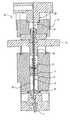
- FIG. 2is a sectional view of a single reservoir/tap unit.
- the unithas a metering tube which is in the up position.
- FIG. 2depicts an offset nozzle embodiment.
- FIG. 3is a sectional view of the reservoir/tap unit shown in FIG. 2, but with the metering tube in the down position.
- FIG. 4is a detail from FIG. 2 .
- the enlarged detail viewshows the tube in the up position, and a piston in the tube.
- the pistonis in the down position, where it rests against a tube plug.
- FIG. 5is the same as FIG. 4, except that the piston is raised into an up position.
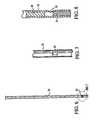
- FIG. 6is an enlarged, front view of a metering tube.
- a tube port, through which liquid enters and leaves the tubeis visible near the lower end of the tube.
- FIG. 7is a detail enlarged from FIG. 6, showing the tube port.
- FIG. 8is an enlarged sectional view (rotated 90° relative to FIG. 6) showing a lower portion of the tube, the tube plug, and a lower portion of the piston.
- FIG. 9is a sectional view (detail) of a reservoir/tap unit in which the metering tube is in the down position, and the piston is in an up position.
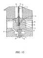
- FIG. 10is a sectional view (detail) of a reservoir/tap unit in which the metering tube is in the down position, and the piston is in a down position.
- FIG. 11is the same as FIG. 10, except that it shows a metered amount of liquid in an upper region of a fluid flow path, and arrows indicating flow of compressed gas through a compressed gas path.
- FIG. 12is the same as FIG. 11, except that it shows the metered amount of liquid in a middle region of the fluid flow path, and arrows indicating flow of compressed gas sweeping the liquid down the fluid flow path.
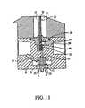
- FIG. 13is the same as FIG. 12, except that it shows the liquid in the lowermost portion of the fluid flow path, where the liquid is exiting from a flow path tip.
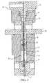
- FIG. 14is a sectional view of a single reservoir/tap unit. The unit has a metering tube in the up position. FIG. 14 depicts an in-line nozzle embodiment.
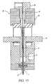
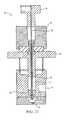
- FIG. 15is a sectional view of the reservoir/tap unit shown in FIG. 14, but with the metering tube in the down position.
- FIG. 16is a detail from FIG. 14 .
- the enlarged detail viewshows the tube in the up position, and a piston in the tube.
- the pistonis in the down position, where it rests against a tube plug.
- FIG. 17is the same as FIG. 16, except that the piston is raised into an up position.
- FIG. 18is a sectional view (detail) of a reservoir/tap unit in which the metering tube is in the down position, and the piston is in an up position.
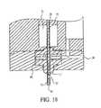
- FIG. 19is a sectional view (detail) of a reservoir/tap unit in which the metering tube is in the down position, and the piston is in the down position.
- FIG. 19shows a bolus of expelled liquid emerging from a port in the side of the tube.
- FIG. 20is a sectional view (detail) of a reservoir/tap unit (in-line nozzle) in which the metering tube has been withdrawn from the down position to the up position, after expulsion of a bolus of liquid. The liquid has been drawn into the fluid output channel in the nozzle.
- FIG. 21is a sectional view of a single nozzleless tapped reservoir unit with the metering tube in the up position.
- FIG. 22is a sectional view of a nozzleless reservoir/tap unit with the metering tube in the down position. A bolus of expelled liquid is shown at the port.
- FIG. 23is a sectional view of a nozzleless reservoir/tap unit with the metering tube in the down position. A bolus of expelled liquid is shown in flight after being propelled from the tip of the metering tube.
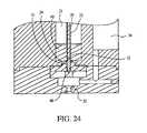
- FIG. 24is a detail from FIG. 21 .
- the enlarged detail viewshows the metering tube in the up position and the piston in the down position.
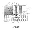
- FIG. 25is the same as FIG. 24, except that the metering tube is in the up position and the piston is in the up position.
- FIG. 26is the same as FIG. 24, except that the metering tube is in the down position and the piston is in the up position.
- FIG. 27is the same as FIG. 24, except that the metering tube is in the down position and the piston is in the down position.
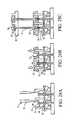
- FIGS. 28A-28Fare sectional views depicting a device and sequence of events in a preferred packaging method.
- the inventionprovides methods and devices for integrated packaging, shipping, storage, and dispensing of extremely small volumes of liquids, e.g., aqueous solutions and compounds dissolved in organic solvents, in an automated, multi-well format of the type used in high throughput screening (HTS) or ultra-high throughput screening (UHTS).
- HTShigh throughput screening
- UHTSultra-high throughput screening
- the inventionadvantageously avoids the use of conventional sip and spit technology. Consequently, multi-well plate assays can be performed without reformatting, i.e., transferring aliquots of concentrated samples from storage plates to working plates, diluting on working plates, transferring diluted samples from working plates to assay plates, etc. This maximizes speed and efficiency.
- Entire sets of samples, e.g., compounds for screening,can be stored and/or shipped conveniently in a single cassette, which can be plugged into an HTS or UHTS system, where nanoliter volumes of concentrated sample can be dispensed directly onto assay plates without reformatting. Because the reservoir/tap units in an array are isolated from each other, single-channel dispensing is achieved, and each reservoir/tap unit is individually addressable. Because each reservoir/tap unit in an array (cassette) can be sealed against air, moisture and light, labile compounds can be stored and handled under favorable conditions.
- FIG. 1is a perspective view of a device 10 according to the invention for storing and dispensing liquid into a conventional 96-well microtiter plate 12 .
- Protruding from lower surface 13 of device 10are 96 flow tips 11 arranged so that when device 10 is aligned above 96-well microtiter plate 12 , each tip 11 is above a different one of the 96 wells 14 in plate 12 .
- On the upper surface 15 of device 10are 96 mechanical interfaces 16 for tap actuation. Operation of each interface 16 actuates a tap whose flow path tip 11 is located beneath that interface 16 .
- FIG. 2is a sectional view of a single reservoir/tap unit 20 .
- the unit 20contains a reservoir 21 formed by a cylinder wall 22 , sliding seal 23 and lower seal 24 .
- the unit 20also contains a metering tube 25 , tube handle 26 , tube handle spring 27 , piston handle 28 , piston 29 , and piston handle stop 30 .
- the embodiment depicted in FIG. 2is an example of an offset nozzle embodiment, because nozzle tip 11 is not directly in line with metering tube 25 .
- FIG. 2shows the tube 25 and tube handle 26 in the up position. Tube handle 26 and piston handle 28 are included in each mechanical interface 16 shown in FIG. 1 .
- FIG. 3is a sectional view of a single unit 20 in which the tube 25 is in the down position.
- FIG. 4is a detail from FIG. 2, in which tube 25 is in the up position and piston 29 is in the down position. In the down position, piston 29 rests against tube plug (tube end closure) 31 so that piston 29 closes and seals tube port 32 , thereby blocking entry of liquid from reservoir 21 into tube 25 .
- FIG. 5is the same as FIG. 4, except that piston 29 is raised into an up position. Raising piston 29 opens tube port 32 and draws a metered amount of liquid from reservoir 21 into tube 25 , with the metered amount depending on the height to which piston 29 is raised.
- FIG. 6is an enlarged, front view of metering tube 25 , showing tube port 32 .
- FIG. 7is a detail from FIG. 6, showing tube port 32 .
- FIG. 8is an enlarged sectional view (rotated 90° relative to FIG. 6) showing a lower portion of tube 25 , tube plug 31 , and a lower portion of piston 29 .
- FIG. 9is sequential, following FIG. 5 .
- metering tube 25has been translated downward into the down position, with piston 29 remaining in the up position, i.e., same position relative to tube 25 .
- downward translation of tube 25 through lower seal 24has taken port 32 out of reservoir 21 and placed port 32 in fluid communication with fluid output channel 33 .
- the next sequential stepis lowering of piston 29 into the down position, in which piston 29 rests against tube plug 31 . This lowering of pistion 29 expels liquid (not shown) from tube 25 and into fluid output path 33 .
- FIG. 11is the same as FIG. 10, except that it shows the expelled liquid 40 in an upper region of fluid output channel 33 , and arrows A indicating flow of compressed air through a compressed gas path 34 , and exit of the compressed air from an annular compressed gas outlet 35 surrounding nozzle tip 11 .
- the exiting airforms an annular curtain of air moving downward and surrounding a droplet of liquid that will exit from nozzle tip 11 .
- the annular curtain of airfacilitates controlled movement of the droplet into the correct well, and effectively isolates all droplets and corresponding wells from each other.
- FIG. 12is the same as FIG. 10, except that it shows a metered amount of expelled liquid 40 (bolus), in a middle region of fluid output channel 33 , and arrows B indicating flow of compressed air in fluid output channel 33 .
- Air flowing from compressed gas inlet 59 through fluid output channel 33sweeps liquid 40 down fluid output channel 33 .
- FIG. 13shows liquid 40 in the lowermost portion of fluid output channel 33 , where it is exiting nozzle tip 11 .
- FIG. 14is a sectional view of a single reservoir/tap unit 20 .
- the unit 20contains a reservoir 21 formed by a cylinder wall 22 , and lower seal 24 .
- the unit 20also contains a metering tube 25 , tube handle 26 , piston handle 28 , piston 29 , and piston handle stop 30 .
- the embodiment depicted in FIG. 14is an example of an in-line nozzle embodiment, because nozzle tip 11 is directly in line with metering tube 25 .
- FIG. 14shows the tube 25 and tube handle 26 in the up position. Tube handle 26 and piston handle 28 are included in each mechanical interface 16 shown in FIG. 1 .
- FIG. 15is a sectional view corresponding to FIG. 14, except that tube 25 is in the down position.
- FIG. 16is a detail from FIG. 14, in which tube 25 is in the up position and piston 29 is in the down position. In the down position, piston 29 rests against tube plug 31 so that piston 29 closes and seals tube port 32 , thereby blocking entry of liquid from reservoir 21 into tube 25 .
- FIG. 17is the same as FIG. 16, except that piston 29 is raised into an up position. Raising piston 29 opens tube port 32 and draws a metered amount of liquid from reservoir 21 into tube 25 , with the metered amount depending on the height to which piston 29 is raised.
- metering tube 25has been translated downward into the down position, with piston 29 remaining in the up position, i.e., same position relative to tube 25 .
- tube 25passes through fluid output channel 33 as it translates between the up position and the down position.
- port 32is beneath nozzle tip 11 .
- the next sequential stepis lowering of piston 29 into the down position, in which piston 29 rests against tube plug 31 , as shown in FIG. 19 . This lowering of piston 29 expels liquid from tube 25 through port 32 .
- a bolus of expelled liquid 40is shown in FIG. 19 .
- Expelled liquid 40clings to the side of tube 25 as a result of surface tension and adhesion.
- nozzle tip 11forces expelled liquid 40 to slide down the outside of tube 25 .
- expelled liquid 40migrates to bottom end 42 of tube 25 and clings there.
- expelled liquid 40follows bottom end 42 of tube 25 upward through fluid output channel 33 (FIG. 20 ).
- expelled liquid 40detaches from bottom end 42 of tube 25 and remains in upper portion of fluid output channel 33 .
- compressed airenters compressed gas path 34 and pushes expelled liquid 40 downward, so that it exits nozzle tip 11 and falls into a well in a microtiter plate (not shown).
- nozzle 45preferably is made of an elastomeric material, with fluid output channel 33 having an inside diameter slightly smaller than the outside diameter of tube 25 . Fluid output channel 33 expands slightly to accommodate tube 25 , as the tube passes through the fluid output channel. This promotes an airtight seal between tube 25 and fluid output channel 33 , when the tube is in the channel. Selection of a suitable elastomer is within ordinary skill in the art.
- FIGS. 21-27depict a nozzleless tapped reservoir.
- reservoir/tap unit 20has metering tube 25 in the up position and piston 29 in the down position.
- FIG. 24is a detail from FIG. 21 in which tube 25 is in the up position and piston 29 is in the down position. In the down position, piston 29 rests against tube plug (tube end closure) 31 so that piston 29 closes and seals tube port 32 , thereby blocking entry of liquid 40 from reservoir 21 .
- FIG. 25is the same as FIG. 24, except that piston 29 is raised into an up position. Raising piston 29 opens tube port 32 and draws a metered amount of liquid from reservoir 21 into tube 25 , with the metered amount depending on the height to which piston 29 is raised.
- FIG. 24is a detail from FIG. 21 in which tube 25 is in the up position and piston 29 is in the down position.
- piston 29rests against tube plug (tube end closure) 31 so that piston 29 closes and seals tube port 32 , thereby blocking entry of liquid 40 from reservoir 21 .
- metering tube 25has been translated downward into the down position, with piston 29 remaining in the up position.
- no fluid output channel or nozzleis necessary, and port 32 and fine point 46 are exposed (FIG. 22 ).
- the next sequential stepis lowering of piston 29 into the down position, where it rests against tube plug 31 , (FIG. 27 ).
- Expelled liquid 40is then swept downward by a downward flow of air from compressed gas outlet 35 .
- FIG. 23shows expelled liquid 40 dropping from bottom end 42 of metering tube 25 , which is tapered to a fine point 46 .
- Fine point 46facilitates release of expelled liquid 40 from bottom end 42 of metering tube 25 in a controlled manner.
- a shroud 57surrounds or partially shields lower end 48 of metering tube 25 , which extends downward when tube 25 is in the expel position.
- FIGS. 28A-28Fdepict a device and sequence of events in a preferred packaging method according to the invention.
- Two reservoir/tap units in an arrayare depicted.
- fill pin 51which has an outside diameter equal to that of metering tube 25 , extends upward through lower seal 24 . This permits dispensing of liquid 40 into reservoir 21 from reservoir filling device 52 positioned above the reservoir.
- cap seal 53is installed on top of reservoir 21 .
- metering tube 25is aligned directly above fill pin 51 , so that tube bottom end 42 contacts upper end 54 of fill pin 51 .
- metering tube 25is lowered so as to push fill pin 51 downward.
- metering tube 25replaces fill pin 51 without allowing leakage of liquid 40 from reservoir 21 .
- metering tube 25is seated against lower seal 24 .
- protective cover 55is installed on bottom of device 20 for storage.
- the lower portion of the deviceserves as a shroud 49 around lower end 48 of metering tube 25 .
- Devices according to the inventioncan be designed for compatibility with various liquids, including aqueous buffers, organic solvents, e.g., dimethylsulfoxide, acids and bases. Compatibility is achieved by selection of suitable materials for fabrication of components that contact the liquid. Exemplary materials for fabrication of components are stainless steel, nylon, polyethylene, polypropylene, EPD rubber and polytetrafluoroethylene (PTFE; Teflon®). Selection of suitable materials and fabrication of components is within ordinary skill in the art.
- sliding seal 23 and lower seal 24can be replaced with an expandable bladder. Accordingly, other embodiments of the invention are within the scope of the following claims.
Landscapes
- Chemical & Material Sciences (AREA)
- Health & Medical Sciences (AREA)
- Physics & Mathematics (AREA)
- Chemical Kinetics & Catalysis (AREA)
- Analytical Chemistry (AREA)
- General Health & Medical Sciences (AREA)
- Biochemistry (AREA)
- General Physics & Mathematics (AREA)
- Immunology (AREA)
- Pathology (AREA)
- Clinical Laboratory Science (AREA)
- Life Sciences & Earth Sciences (AREA)
- Organic Chemistry (AREA)
- Fluid Mechanics (AREA)
- Feeding, Discharge, Calcimining, Fusing, And Gas-Generation Devices (AREA)
Abstract
Description
Claims (6)
Priority Applications (4)
| Application Number | Priority Date | Filing Date | Title |
|---|---|---|---|
| US09/591,807US6706538B1 (en) | 2000-02-29 | 2000-06-12 | Microvolume liquid dispensing array |
| EP01913075AEP1261430A2 (en) | 2000-02-29 | 2001-02-27 | Microvolume liquid dispensing |
| PCT/US2001/006174WO2001064345A2 (en) | 2000-02-29 | 2001-02-27 | Microvolume liquid dispensing |
| AU2001241780AAU2001241780A1 (en) | 2000-02-29 | 2001-02-27 | Microvolume liquid dispensing |
Applications Claiming Priority (2)
| Application Number | Priority Date | Filing Date | Title |
|---|---|---|---|
| US18581000P | 2000-02-29 | 2000-02-29 | |
| US09/591,807US6706538B1 (en) | 2000-02-29 | 2000-06-12 | Microvolume liquid dispensing array |
Publications (1)
| Publication Number | Publication Date |
|---|---|
| US6706538B1true US6706538B1 (en) | 2004-03-16 |
Family
ID=31949758
Family Applications (1)
| Application Number | Title | Priority Date | Filing Date |
|---|---|---|---|
| US09/591,807Expired - Fee RelatedUS6706538B1 (en) | 2000-02-29 | 2000-06-12 | Microvolume liquid dispensing array |
Country Status (1)
| Country | Link |
|---|---|
| US (1) | US6706538B1 (en) |
Cited By (22)
| Publication number | Priority date | Publication date | Assignee | Title |
|---|---|---|---|---|
| US20020192716A1 (en)* | 1999-03-19 | 2002-12-19 | Volker Schellenberger | Multi-through hole testing plate for high throughput screening |
| US20030039585A1 (en)* | 2001-08-24 | 2003-02-27 | Freeman Alex Reddy | Novel micro array for high throughput screening |
| US20040037748A1 (en)* | 2002-08-23 | 2004-02-26 | Leila Hasan | Voltage-aided transfer pins |
| US20040191924A1 (en)* | 1998-01-12 | 2004-09-30 | Massachusetts Institute Of Technology | Reformatted through-hole arrays |
| US20040208792A1 (en)* | 2002-12-20 | 2004-10-21 | John Linton | Assay apparatus and method using microfluidic arrays |
| US20040208794A1 (en)* | 2002-08-13 | 2004-10-21 | Karg Jeffrey A. | Microfluidic mixing and dispensing |
| US20050181519A1 (en)* | 2004-02-17 | 2005-08-18 | Karg Jeffrey A. | Metering doses of sample liquids |
| US20060051250A1 (en)* | 2004-09-07 | 2006-03-09 | Gonzalez Jose M | Microtray for handling biosubstances |
| US20070280855A1 (en)* | 2006-06-01 | 2007-12-06 | Disc Dynamics, Inc. | Modular And Reconfigurable Multi-Stage Microreactor Cartridge Apparatus |
| US20080181829A1 (en)* | 2006-08-23 | 2008-07-31 | Matteo Joseph C | Modular and reconfigurable multi-stage high temperature microreactor cartridge apparatus and system for using same |
| US7427379B1 (en)* | 1999-03-19 | 2008-09-23 | Biotage Ab | Liquid dispensing apparatus |
| US20090104078A1 (en)* | 2007-10-18 | 2009-04-23 | Matrix Technologies Corporation | Apparatus and method for dispensing small volume liquid samples |
| US7604983B2 (en) | 2000-02-18 | 2009-10-20 | Board Of Trustees Of The Leland Stanford Junior University | Apparatus and methods for parallel processing of micro-volume liquid reactions |
| US7797988B2 (en) | 2007-03-23 | 2010-09-21 | Advion Biosystems, Inc. | Liquid chromatography-mass spectrometry |
| US20110003699A1 (en)* | 2002-12-20 | 2011-01-06 | Biotrove, Inc. | Thermal Cycler for Microfluidic Array Assays |
| US20110056439A1 (en)* | 2009-09-07 | 2011-03-10 | Takashi Tobita | Automatic water supply nozzle for animals and automatic water supply cap for animals |
| US7998418B1 (en) | 2006-06-01 | 2011-08-16 | Nanotek, Llc | Evaporator and concentrator in reactor and loading system |
| US8105554B2 (en) | 2004-03-12 | 2012-01-31 | Life Technologies Corporation | Nanoliter array loading |
| WO2014144201A1 (en)* | 2013-03-15 | 2014-09-18 | Douglas Scientific | Wash through pipettor |
| US9399216B2 (en) | 2013-12-30 | 2016-07-26 | General Electric Company | Fluid transport in microfluidic applications with sensors for detecting fluid presence and pressure |
| US10076751B2 (en) | 2013-12-30 | 2018-09-18 | General Electric Company | Systems and methods for reagent storage |
| US10363399B2 (en) | 2014-09-30 | 2019-07-30 | Boston Scientific Scimed, Inc. | Dual-layer balloon design and method of making the same |
Citations (40)
| Publication number | Priority date | Publication date | Assignee | Title |
|---|---|---|---|---|
| US3167398A (en)* | 1961-06-23 | 1965-01-26 | Phillips Petroleum Co | Metering apparatus |
| US3568735A (en)* | 1968-06-26 | 1971-03-09 | Cooke Eng Co | Laboratory microtitration dispensing apparatus |
| US3650306A (en)* | 1970-09-18 | 1972-03-21 | Cooke Eng Co | Laboratory dispensing apparatus |
| US4120205A (en) | 1976-07-22 | 1978-10-17 | Merck Patent Gesellschaft Mit Beschrankter Haftung | Device for the repeated reproducible delivery of definite variable amounts by volume |
| US4180239A (en) | 1977-06-13 | 1979-12-25 | Electron Fusion Devices Inc. | Metering valves |
| US4487081A (en)* | 1982-08-27 | 1984-12-11 | Donald H. De Vaughn | Pipetting techniques using replaceable tips |
| US4565100A (en)* | 1981-10-02 | 1986-01-21 | Culture-Tek | Pipette device |
| US4806313A (en)* | 1985-04-12 | 1989-02-21 | E. I. Du Pont De Nemours And Company | Rapid assay processor |
| US4844868A (en) | 1985-06-18 | 1989-07-04 | Kabushiki Kaisha Toshiba | Automatic chemical analysis reagent distribution and analysis apparatus |
| US4875605A (en)* | 1986-12-17 | 1989-10-24 | Microvol Limited | Pressurized metering dispenser |
| WO1990008075A1 (en)* | 1989-01-12 | 1990-07-26 | Microvol Limited | Pressurised metering dispenser |
| US4973450A (en)* | 1987-06-10 | 1990-11-27 | Hoyer Gmbh And Company | Device for urinalysis |
| US5055263A (en)* | 1988-01-14 | 1991-10-08 | Cyberlab, Inc. | Automated pipetting system |
| US5226462A (en)* | 1991-07-26 | 1993-07-13 | Carl Richard A | Introducing measured amounts of liquid into receptacles |
| US5272926A (en)* | 1991-11-13 | 1993-12-28 | Wilkins Judd R | Microbial retrieval and sampling pipette with a removable cover |
| US5421492A (en)* | 1993-11-02 | 1995-06-06 | Glaxo Inc. | Metered aerosol dispensing apparatus and method of use thereof |
| US5440940A (en)* | 1994-03-18 | 1995-08-15 | Wilkins; Judd R. | Pipette-syringe-tubular microbial retrieval and sampler |
| WO1998004358A1 (en)* | 1996-07-26 | 1998-02-05 | Bio-Dot, Inc. | Dispensing apparatus having improved dynamic range |
| US5741554A (en) | 1996-07-26 | 1998-04-21 | Bio Dot, Inc. | Method of dispensing a liquid reagent |
| US5743960A (en) | 1996-07-26 | 1998-04-28 | Bio-Dot, Inc. | Precision metered solenoid valve dispenser |
| US5756050A (en) | 1993-08-11 | 1998-05-26 | University Of Chicago | Device of dispensing micro doses of aqueous solutions of substances onto a carrier and device for carrying out said method |
| US5770158A (en)* | 1996-06-13 | 1998-06-23 | Diametrics Medical, Inc. | Capillary syringe |
| US5876675A (en) | 1997-08-05 | 1999-03-02 | Caliper Technologies Corp. | Microfluidic devices and systems |
| WO1999010099A1 (en) | 1997-08-26 | 1999-03-04 | Eppendorf-Netheler-Hinz Gmbh | Micrometering system |
| WO1999015876A1 (en) | 1997-09-19 | 1999-04-01 | Aclara Biosciences, Inc. | Apparatus and method for transferring liquids |
| WO1999017749A1 (en) | 1997-10-02 | 1999-04-15 | Iep Group, Inc. | A micromachined valve for fluid applications |
| WO1999042752A1 (en) | 1998-02-20 | 1999-08-26 | Bio Dot, Inc. | Reagent dispensing valve |
| WO1999043432A1 (en) | 1998-02-24 | 1999-09-02 | Caliper Technologies Corporation | Microfluidic devices and systems incorporating cover layers |
| US5957167A (en)* | 1997-12-18 | 1999-09-28 | Pharmacopeia, Inc. | Article for dispensing small volumes of liquid |
| US5988435A (en)* | 1997-07-09 | 1999-11-23 | Barnstead/Thermolyne Corporation | Fluid dispensing system |
| WO1999061881A2 (en) | 1998-05-27 | 1999-12-02 | MAX-PLANCK-Gesellschaft zur Förderung der Wissenschaften e.V. | Method and device for processing extremely small substance quantities |
| US6024925A (en) | 1997-01-23 | 2000-02-15 | Sequenom, Inc. | Systems and methods for preparing low volume analyte array elements |
| WO2000024511A1 (en) | 1998-10-26 | 2000-05-04 | The Regents Of The University Of California | An integrated titer plate-injector head for microdrop array preparation, storage and transfer |
| US6063339A (en)* | 1998-01-09 | 2000-05-16 | Cartesian Technologies, Inc. | Method and apparatus for high-speed dot array dispensing |
| US6093574A (en)* | 1997-08-11 | 2000-07-25 | Ventana Medical Systems | Method and apparatus for rinsing a microscope slide |
| US6109717A (en) | 1997-05-13 | 2000-08-29 | Sarnoff Corporation | Multi-element fluid delivery apparatus and methods |
| US6182719B1 (en)* | 1998-05-08 | 2001-02-06 | Matsushita Electric Industrial Co., Ltd. | Distribution apparatus, distribution method and method of fitting distribution tips |
| US6228659B1 (en)* | 1997-10-31 | 2001-05-08 | PE Corporation (“NY”) | Method and apparatus for making arrays |
| US20010019845A1 (en)* | 1998-08-07 | 2001-09-06 | Klaus Bienert | Metering head for parallel processing of a plurality of fluid samples |
| US6309891B1 (en)* | 1998-09-09 | 2001-10-30 | Incyte Genomics, Inc. | Capillary printing systems |
- 2000
- 2000-06-12USUS09/591,807patent/US6706538B1/ennot_activeExpired - Fee Related
Patent Citations (41)
| Publication number | Priority date | Publication date | Assignee | Title |
|---|---|---|---|---|
| US3167398A (en)* | 1961-06-23 | 1965-01-26 | Phillips Petroleum Co | Metering apparatus |
| US3568735A (en)* | 1968-06-26 | 1971-03-09 | Cooke Eng Co | Laboratory microtitration dispensing apparatus |
| US3650306A (en)* | 1970-09-18 | 1972-03-21 | Cooke Eng Co | Laboratory dispensing apparatus |
| US4120205A (en) | 1976-07-22 | 1978-10-17 | Merck Patent Gesellschaft Mit Beschrankter Haftung | Device for the repeated reproducible delivery of definite variable amounts by volume |
| US4180239A (en) | 1977-06-13 | 1979-12-25 | Electron Fusion Devices Inc. | Metering valves |
| US4565100A (en)* | 1981-10-02 | 1986-01-21 | Culture-Tek | Pipette device |
| US4487081A (en)* | 1982-08-27 | 1984-12-11 | Donald H. De Vaughn | Pipetting techniques using replaceable tips |
| US4806313A (en)* | 1985-04-12 | 1989-02-21 | E. I. Du Pont De Nemours And Company | Rapid assay processor |
| US4844868A (en) | 1985-06-18 | 1989-07-04 | Kabushiki Kaisha Toshiba | Automatic chemical analysis reagent distribution and analysis apparatus |
| US4875605A (en)* | 1986-12-17 | 1989-10-24 | Microvol Limited | Pressurized metering dispenser |
| US4973450A (en)* | 1987-06-10 | 1990-11-27 | Hoyer Gmbh And Company | Device for urinalysis |
| US5055263A (en)* | 1988-01-14 | 1991-10-08 | Cyberlab, Inc. | Automated pipetting system |
| WO1990008075A1 (en)* | 1989-01-12 | 1990-07-26 | Microvol Limited | Pressurised metering dispenser |
| US5226462A (en)* | 1991-07-26 | 1993-07-13 | Carl Richard A | Introducing measured amounts of liquid into receptacles |
| US5272926A (en)* | 1991-11-13 | 1993-12-28 | Wilkins Judd R | Microbial retrieval and sampling pipette with a removable cover |
| US5756050A (en) | 1993-08-11 | 1998-05-26 | University Of Chicago | Device of dispensing micro doses of aqueous solutions of substances onto a carrier and device for carrying out said method |
| US5962329A (en) | 1993-08-11 | 1999-10-05 | University Of Chicago | Method of dispensing microdoses of aqueous solutions of substances onto a carrier and a device for carrying out said method |
| US5421492A (en)* | 1993-11-02 | 1995-06-06 | Glaxo Inc. | Metered aerosol dispensing apparatus and method of use thereof |
| US5440940A (en)* | 1994-03-18 | 1995-08-15 | Wilkins; Judd R. | Pipette-syringe-tubular microbial retrieval and sampler |
| US5770158A (en)* | 1996-06-13 | 1998-06-23 | Diametrics Medical, Inc. | Capillary syringe |
| US5741554A (en) | 1996-07-26 | 1998-04-21 | Bio Dot, Inc. | Method of dispensing a liquid reagent |
| US5743960A (en) | 1996-07-26 | 1998-04-28 | Bio-Dot, Inc. | Precision metered solenoid valve dispenser |
| WO1998004358A1 (en)* | 1996-07-26 | 1998-02-05 | Bio-Dot, Inc. | Dispensing apparatus having improved dynamic range |
| US6024925A (en) | 1997-01-23 | 2000-02-15 | Sequenom, Inc. | Systems and methods for preparing low volume analyte array elements |
| US6109717A (en) | 1997-05-13 | 2000-08-29 | Sarnoff Corporation | Multi-element fluid delivery apparatus and methods |
| US5988435A (en)* | 1997-07-09 | 1999-11-23 | Barnstead/Thermolyne Corporation | Fluid dispensing system |
| US5876675A (en) | 1997-08-05 | 1999-03-02 | Caliper Technologies Corp. | Microfluidic devices and systems |
| US6093574A (en)* | 1997-08-11 | 2000-07-25 | Ventana Medical Systems | Method and apparatus for rinsing a microscope slide |
| WO1999010099A1 (en) | 1997-08-26 | 1999-03-04 | Eppendorf-Netheler-Hinz Gmbh | Micrometering system |
| WO1999015876A1 (en) | 1997-09-19 | 1999-04-01 | Aclara Biosciences, Inc. | Apparatus and method for transferring liquids |
| WO1999017749A1 (en) | 1997-10-02 | 1999-04-15 | Iep Group, Inc. | A micromachined valve for fluid applications |
| US6228659B1 (en)* | 1997-10-31 | 2001-05-08 | PE Corporation (“NY”) | Method and apparatus for making arrays |
| US5957167A (en)* | 1997-12-18 | 1999-09-28 | Pharmacopeia, Inc. | Article for dispensing small volumes of liquid |
| US6063339A (en)* | 1998-01-09 | 2000-05-16 | Cartesian Technologies, Inc. | Method and apparatus for high-speed dot array dispensing |
| WO1999042752A1 (en) | 1998-02-20 | 1999-08-26 | Bio Dot, Inc. | Reagent dispensing valve |
| WO1999043432A1 (en) | 1998-02-24 | 1999-09-02 | Caliper Technologies Corporation | Microfluidic devices and systems incorporating cover layers |
| US6182719B1 (en)* | 1998-05-08 | 2001-02-06 | Matsushita Electric Industrial Co., Ltd. | Distribution apparatus, distribution method and method of fitting distribution tips |
| WO1999061881A2 (en) | 1998-05-27 | 1999-12-02 | MAX-PLANCK-Gesellschaft zur Förderung der Wissenschaften e.V. | Method and device for processing extremely small substance quantities |
| US20010019845A1 (en)* | 1998-08-07 | 2001-09-06 | Klaus Bienert | Metering head for parallel processing of a plurality of fluid samples |
| US6309891B1 (en)* | 1998-09-09 | 2001-10-30 | Incyte Genomics, Inc. | Capillary printing systems |
| WO2000024511A1 (en) | 1998-10-26 | 2000-05-04 | The Regents Of The University Of California | An integrated titer plate-injector head for microdrop array preparation, storage and transfer |
Cited By (59)
| Publication number | Priority date | Publication date | Assignee | Title |
|---|---|---|---|---|
| US8029745B2 (en) | 1998-01-12 | 2011-10-04 | Massachusetts Institute Of Technology | Systems for filling a sample array by droplet dragging |
| US7547556B2 (en) | 1998-01-12 | 2009-06-16 | Massachusetts Institute Of Technology | Methods for filing a sample array by droplet dragging |
| US20040191924A1 (en)* | 1998-01-12 | 2004-09-30 | Massachusetts Institute Of Technology | Reformatted through-hole arrays |
| US20050079105A1 (en)* | 1998-01-12 | 2005-04-14 | Massachusetts Institute Of Technology | Methods for filing a sample array by droplet dragging |
| US10195579B2 (en) | 1999-03-19 | 2019-02-05 | Life Technologies Corporation | Multi-through hole testing plate for high throughput screening |
| US20020192716A1 (en)* | 1999-03-19 | 2002-12-19 | Volker Schellenberger | Multi-through hole testing plate for high throughput screening |
| US7427379B1 (en)* | 1999-03-19 | 2008-09-23 | Biotage Ab | Liquid dispensing apparatus |
| US7666360B2 (en) | 1999-03-19 | 2010-02-23 | Biotrove, Inc. | Multi-through hole testing plate for high throughput screening |
| US9518299B2 (en) | 2000-02-18 | 2016-12-13 | The Board Of Trustees Of The Leland Stanford Junior University | Apparatus and methods for parallel processing of micro-volume liquid reactions |
| US10227644B2 (en) | 2000-02-18 | 2019-03-12 | The Board Of Trustees Of The Leland Stanford Junior University | Apparatus and methods for parallel processing of microvolume liquid reactions |
| US8906618B2 (en) | 2000-02-18 | 2014-12-09 | The Board Of Trustees Of The Leland Stanford Junior University | Apparatus and methods for parallel processing of micro-volume liquid reactions |
| US10378049B2 (en) | 2000-02-18 | 2019-08-13 | The Board Of Trustees Of The Leland Stanford Junior University | Apparatus and methods for parallel processing of microvolume liquid reactions |
| US7604983B2 (en) | 2000-02-18 | 2009-10-20 | Board Of Trustees Of The Leland Stanford Junior University | Apparatus and methods for parallel processing of micro-volume liquid reactions |
| US6969489B2 (en)* | 2001-08-24 | 2005-11-29 | Cytoplex Biosciences | Micro array for high throughout screening |
| US20030039585A1 (en)* | 2001-08-24 | 2003-02-27 | Freeman Alex Reddy | Novel micro array for high throughput screening |
| US20040208794A1 (en)* | 2002-08-13 | 2004-10-21 | Karg Jeffrey A. | Microfluidic mixing and dispensing |
| US7459128B2 (en) | 2002-08-13 | 2008-12-02 | Molecular Bioproducts, Inc. | Microfluidic mixing and dispensing |
| US20090054266A1 (en)* | 2002-08-23 | 2009-02-26 | Biotrove, Inc. | Microfluidic transfer pin |
| US8685340B2 (en) | 2002-08-23 | 2014-04-01 | Life Technologies Corporation | Microfluidic transfer pin |
| US8277753B2 (en) | 2002-08-23 | 2012-10-02 | Life Technologies Corporation | Microfluidic transfer pin |
| US20040037748A1 (en)* | 2002-08-23 | 2004-02-26 | Leila Hasan | Voltage-aided transfer pins |
| US8697452B2 (en) | 2002-12-20 | 2014-04-15 | Life Technologies Corporation | Thermal cycling assay apparatus and method |
| US20110003699A1 (en)* | 2002-12-20 | 2011-01-06 | Biotrove, Inc. | Thermal Cycler for Microfluidic Array Assays |
| US20090062152A1 (en)* | 2002-12-20 | 2009-03-05 | Biotrove, Inc. | Thermal cycling apparatus and method |
| US9428800B2 (en) | 2002-12-20 | 2016-08-30 | Life Technologies Corporation | Thermal cycling apparatus and method |
| US7682565B2 (en) | 2002-12-20 | 2010-03-23 | Biotrove, Inc. | Assay apparatus and method using microfluidic arrays |
| US20040208792A1 (en)* | 2002-12-20 | 2004-10-21 | John Linton | Assay apparatus and method using microfluidic arrays |
| US20090062134A1 (en)* | 2002-12-20 | 2009-03-05 | Biotrove, Inc. | Assay imaging apparatus and methods |
| US20110027906A1 (en)* | 2004-02-17 | 2011-02-03 | MOLECULAR BIOPRODUCTS, INC., a California corporation | Metering doses of sample liquids |
| US20050181519A1 (en)* | 2004-02-17 | 2005-08-18 | Karg Jeffrey A. | Metering doses of sample liquids |
| US20100008827A1 (en)* | 2004-02-17 | 2010-01-14 | Molecular BioProducts, Inc. a Delaware corporation | Metering doses of sample liquids |
| US7592185B2 (en) | 2004-02-17 | 2009-09-22 | Molecular Bioproducts, Inc. | Metering doses of sample liquids |
| US8043865B2 (en) | 2004-02-17 | 2011-10-25 | Molecular Bioproducts, Inc. | Metering doses of sample liquids |
| US8080218B2 (en) | 2004-02-17 | 2011-12-20 | Molecular Bio-Products, Inc. | Metering doses of sample liquids |
| US10065189B2 (en) | 2004-03-12 | 2018-09-04 | Life Technologies Corporation | Nanoliter array loading |
| US8105554B2 (en) | 2004-03-12 | 2012-01-31 | Life Technologies Corporation | Nanoliter array loading |
| US10974247B2 (en) | 2004-03-12 | 2021-04-13 | Life Technologies Corporation | Nanoliter array loading |
| US9266108B2 (en) | 2004-03-12 | 2016-02-23 | Life Technologies Corporation | Nanoliter array loading |
| US8545772B2 (en) | 2004-03-12 | 2013-10-01 | Life Technologies Corporation | Nanoliter array loading |
| US20060051250A1 (en)* | 2004-09-07 | 2006-03-09 | Gonzalez Jose M | Microtray for handling biosubstances |
| US7651665B2 (en) | 2004-09-07 | 2010-01-26 | Hewlett-Packard Development Company, L.P. | Microtray for handling biosubstances |
| US20070280855A1 (en)* | 2006-06-01 | 2007-12-06 | Disc Dynamics, Inc. | Modular And Reconfigurable Multi-Stage Microreactor Cartridge Apparatus |
| US7998418B1 (en) | 2006-06-01 | 2011-08-16 | Nanotek, Llc | Evaporator and concentrator in reactor and loading system |
| US7790124B2 (en) | 2006-06-01 | 2010-09-07 | Nanotek, Llc | Modular and reconfigurable multi-stage microreactor cartridge apparatus |
| US7641860B2 (en) | 2006-06-01 | 2010-01-05 | Nanotek, Llc | Modular and reconfigurable multi-stage microreactor cartridge apparatus |
| US20080181829A1 (en)* | 2006-08-23 | 2008-07-31 | Matteo Joseph C | Modular and reconfigurable multi-stage high temperature microreactor cartridge apparatus and system for using same |
| US7854902B2 (en) | 2006-08-23 | 2010-12-21 | Nanotek, Llc | Modular and reconfigurable multi-stage high temperature microreactor cartridge apparatus and system for using same |
| US7797988B2 (en) | 2007-03-23 | 2010-09-21 | Advion Biosystems, Inc. | Liquid chromatography-mass spectrometry |
| US20090104078A1 (en)* | 2007-10-18 | 2009-04-23 | Matrix Technologies Corporation | Apparatus and method for dispensing small volume liquid samples |
| US8136482B2 (en)* | 2009-09-07 | 2012-03-20 | Takashi Tobita | Automatic water supply nozzle for animals and automatic water supply cap for animals |
| US20110056439A1 (en)* | 2009-09-07 | 2011-03-10 | Takashi Tobita | Automatic water supply nozzle for animals and automatic water supply cap for animals |
| US12005433B2 (en) | 2013-03-15 | 2024-06-11 | LGC Genomics, LLC | Wash through pipettor |
| US9415386B2 (en) | 2013-03-15 | 2016-08-16 | Douglas Scientific, LLC | Wash through pipettor |
| WO2014144201A1 (en)* | 2013-03-15 | 2014-09-18 | Douglas Scientific | Wash through pipettor |
| US11045801B2 (en) | 2013-03-15 | 2021-06-29 | Douglas Scientific, LLC | Wash through pipettor |
| CN105209922A (en)* | 2013-03-15 | 2015-12-30 | 道格拉斯科学有限责任公司 | Pass-Through Cleaning Pipettes |
| US9399216B2 (en) | 2013-12-30 | 2016-07-26 | General Electric Company | Fluid transport in microfluidic applications with sensors for detecting fluid presence and pressure |
| US10076751B2 (en) | 2013-12-30 | 2018-09-18 | General Electric Company | Systems and methods for reagent storage |
| US10363399B2 (en) | 2014-09-30 | 2019-07-30 | Boston Scientific Scimed, Inc. | Dual-layer balloon design and method of making the same |
Similar Documents
| Publication | Publication Date | Title |
|---|---|---|
| US6706538B1 (en) | Microvolume liquid dispensing array | |
| US7459128B2 (en) | Microfluidic mixing and dispensing | |
| US7185551B2 (en) | Pipetting module | |
| US6911181B1 (en) | Self-dispensing storage device | |
| US6488894B1 (en) | Device for sequential discharge of flowable reagents | |
| US6824024B2 (en) | Device for the take-up and/or release of liquid samples | |
| US5260030A (en) | Calibrated pipette tip and method | |
| EP1155742B1 (en) | Liquid dispensing apparatus and method | |
| US6374683B1 (en) | Pipetter | |
| US8273307B2 (en) | Microdispenser and associated operating method | |
| US6694197B1 (en) | Single channel reformatter | |
| US9091670B2 (en) | Cleaning of system for dispensing of liquid droplets | |
| AU2001294769A1 (en) | Self-dispensing storage device | |
| US6620383B1 (en) | Microvolume liquid dispensing device | |
| US6709872B1 (en) | Method and apparatus for dispensing low nanoliter volumes of liquid while minimizing waste | |
| US20040013572A1 (en) | Device for fully automated solid phase extraction | |
| WO2001064345A2 (en) | Microvolume liquid dispensing | |
| US7563410B2 (en) | Solid phase extraction apparatus and method | |
| WO2003016832A2 (en) | Microfluidic mixing and dispensing | |
| US20020164821A1 (en) | Liquid dispensing device | |
| US4991610A (en) | Rinsing liquid apparatus for analytical instruments | |
| US3203251A (en) | Pipette apparatus | |
| US12305625B2 (en) | Liquid dispenser | |
| US11820140B2 (en) | Dispense modes for multi-mode capable device | |
| US20070008387A1 (en) | Apparatus for dispensing and printing fluids |
Legal Events
| Date | Code | Title | Description |
|---|---|---|---|
| AS | Assignment | Owner name:BOSTON INNOVATION INC., MASSACHUSETTS Free format text:ASSIGNMENT OF ASSIGNORS INTEREST;ASSIGNORS:KRONCKE, DOUGLAS W.;KARG, JEFFREY A.;REEL/FRAME:011206/0148 Effective date:20001019 | |
| AS | Assignment | Owner name:BOSTON INNOVATION, INC., MASSACHUSETTS Free format text:ASSIGNMENT OF ASSIGNORS INTEREST;ASSIGNOR:JOBIN, MICHAEL J.;REEL/FRAME:011532/0596 Effective date:20010209 | |
| AS | Assignment | Owner name:NASCENT BIOSCIENCES, INC., MASSACHUSETTS Free format text:ASSIGNMENT OF ASSIGNORS INTEREST;ASSIGNOR:BOSTON INNOVATION, INC.;REEL/FRAME:015509/0980 Effective date:20041229 | |
| FEPP | Fee payment procedure | Free format text:PAYOR NUMBER ASSIGNED (ORIGINAL EVENT CODE: ASPN); ENTITY STATUS OF PATENT OWNER: SMALL ENTITY | |
| FPAY | Fee payment | Year of fee payment:4 | |
| REMI | Maintenance fee reminder mailed | ||
| AS | Assignment | Owner name:APOGENT HOLDING COMPANY, NEW HAMPSHIRE Free format text:NUNC PRO TUNC ASSIGNMENT;ASSIGNOR:NASCENT BIOSCIENCES INC.;REEL/FRAME:021387/0693 Effective date:20080414 Owner name:MOLECULAR BIOPRODUCTS, INC., CALIFORNIA Free format text:NUNC PRO TUNC ASSIGNMENT;ASSIGNOR:APOGENT HOLDING COMPANY;REEL/FRAME:021387/0709 Effective date:20080724 | |
| REMI | Maintenance fee reminder mailed | ||
| FEPP | Fee payment procedure | Free format text:PAYER NUMBER DE-ASSIGNED (ORIGINAL EVENT CODE: RMPN); ENTITY STATUS OF PATENT OWNER: SMALL ENTITY Free format text:PAYOR NUMBER ASSIGNED (ORIGINAL EVENT CODE: ASPN); ENTITY STATUS OF PATENT OWNER: SMALL ENTITY | |
| LAPS | Lapse for failure to pay maintenance fees | ||
| STCH | Information on status: patent discontinuation | Free format text:PATENT EXPIRED DUE TO NONPAYMENT OF MAINTENANCE FEES UNDER 37 CFR 1.362 | |
| FP | Lapsed due to failure to pay maintenance fee | Effective date:20120316 |