US6706070B1 - Multi-variable-height fusion device - Google Patents
Multi-variable-height fusion deviceDownload PDFInfo
- Publication number
- US6706070B1 US6706070B1US09/070,116US7011698AUS6706070B1US 6706070 B1US6706070 B1US 6706070B1US 7011698 AUS7011698 AUS 7011698AUS 6706070 B1US6706070 B1US 6706070B1
- Authority
- US
- United States
- Prior art keywords
- engaging plates
- screw
- turnbuckle
- spinal implant
- fusion device
- Prior art date
- Legal status (The legal status is an assumption and is not a legal conclusion. Google has not performed a legal analysis and makes no representation as to the accuracy of the status listed.)
- Expired - Lifetime
Links
Images


Classifications
- A—HUMAN NECESSITIES
- A61—MEDICAL OR VETERINARY SCIENCE; HYGIENE
- A61F—FILTERS IMPLANTABLE INTO BLOOD VESSELS; PROSTHESES; DEVICES PROVIDING PATENCY TO, OR PREVENTING COLLAPSING OF, TUBULAR STRUCTURES OF THE BODY, e.g. STENTS; ORTHOPAEDIC, NURSING OR CONTRACEPTIVE DEVICES; FOMENTATION; TREATMENT OR PROTECTION OF EYES OR EARS; BANDAGES, DRESSINGS OR ABSORBENT PADS; FIRST-AID KITS
- A61F2/00—Filters implantable into blood vessels; Prostheses, i.e. artificial substitutes or replacements for parts of the body; Appliances for connecting them with the body; Devices providing patency to, or preventing collapsing of, tubular structures of the body, e.g. stents
- A61F2/02—Prostheses implantable into the body
- A61F2/30—Joints
- A61F2/44—Joints for the spine, e.g. vertebrae, spinal discs
- A61F2/4455—Joints for the spine, e.g. vertebrae, spinal discs for the fusion of spinal bodies, e.g. intervertebral fusion of adjacent spinal bodies, e.g. fusion cages
- A—HUMAN NECESSITIES
- A61—MEDICAL OR VETERINARY SCIENCE; HYGIENE
- A61F—FILTERS IMPLANTABLE INTO BLOOD VESSELS; PROSTHESES; DEVICES PROVIDING PATENCY TO, OR PREVENTING COLLAPSING OF, TUBULAR STRUCTURES OF THE BODY, e.g. STENTS; ORTHOPAEDIC, NURSING OR CONTRACEPTIVE DEVICES; FOMENTATION; TREATMENT OR PROTECTION OF EYES OR EARS; BANDAGES, DRESSINGS OR ABSORBENT PADS; FIRST-AID KITS
- A61F2/00—Filters implantable into blood vessels; Prostheses, i.e. artificial substitutes or replacements for parts of the body; Appliances for connecting them with the body; Devices providing patency to, or preventing collapsing of, tubular structures of the body, e.g. stents
- A61F2/02—Prostheses implantable into the body
- A61F2/30—Joints
- A61F2/44—Joints for the spine, e.g. vertebrae, spinal discs
- A—HUMAN NECESSITIES
- A61—MEDICAL OR VETERINARY SCIENCE; HYGIENE
- A61B—DIAGNOSIS; SURGERY; IDENTIFICATION
- A61B17/00—Surgical instruments, devices or methods
- A61B17/56—Surgical instruments or methods for treatment of bones or joints; Devices specially adapted therefor
- A61B17/58—Surgical instruments or methods for treatment of bones or joints; Devices specially adapted therefor for osteosynthesis, e.g. bone plates, screws or setting implements
- A61B17/88—Osteosynthesis instruments; Methods or means for implanting or extracting internal or external fixation devices
- A61B17/8875—Screwdrivers, spanners or wrenches
- A—HUMAN NECESSITIES
- A61—MEDICAL OR VETERINARY SCIENCE; HYGIENE
- A61F—FILTERS IMPLANTABLE INTO BLOOD VESSELS; PROSTHESES; DEVICES PROVIDING PATENCY TO, OR PREVENTING COLLAPSING OF, TUBULAR STRUCTURES OF THE BODY, e.g. STENTS; ORTHOPAEDIC, NURSING OR CONTRACEPTIVE DEVICES; FOMENTATION; TREATMENT OR PROTECTION OF EYES OR EARS; BANDAGES, DRESSINGS OR ABSORBENT PADS; FIRST-AID KITS
- A61F2/00—Filters implantable into blood vessels; Prostheses, i.e. artificial substitutes or replacements for parts of the body; Appliances for connecting them with the body; Devices providing patency to, or preventing collapsing of, tubular structures of the body, e.g. stents
- A61F2/02—Prostheses implantable into the body
- A61F2/30—Joints
- A61F2/30721—Accessories
- A61F2/30724—Spacers for centering an implant in a bone cavity, e.g. in a cement-receiving cavity
- A—HUMAN NECESSITIES
- A61—MEDICAL OR VETERINARY SCIENCE; HYGIENE
- A61F—FILTERS IMPLANTABLE INTO BLOOD VESSELS; PROSTHESES; DEVICES PROVIDING PATENCY TO, OR PREVENTING COLLAPSING OF, TUBULAR STRUCTURES OF THE BODY, e.g. STENTS; ORTHOPAEDIC, NURSING OR CONTRACEPTIVE DEVICES; FOMENTATION; TREATMENT OR PROTECTION OF EYES OR EARS; BANDAGES, DRESSINGS OR ABSORBENT PADS; FIRST-AID KITS
- A61F2/00—Filters implantable into blood vessels; Prostheses, i.e. artificial substitutes or replacements for parts of the body; Appliances for connecting them with the body; Devices providing patency to, or preventing collapsing of, tubular structures of the body, e.g. stents
- A61F2/02—Prostheses implantable into the body
- A61F2/30—Joints
- A61F2/30721—Accessories
- A61F2/30744—End caps, e.g. for closing an endoprosthetic cavity
- A—HUMAN NECESSITIES
- A61—MEDICAL OR VETERINARY SCIENCE; HYGIENE
- A61F—FILTERS IMPLANTABLE INTO BLOOD VESSELS; PROSTHESES; DEVICES PROVIDING PATENCY TO, OR PREVENTING COLLAPSING OF, TUBULAR STRUCTURES OF THE BODY, e.g. STENTS; ORTHOPAEDIC, NURSING OR CONTRACEPTIVE DEVICES; FOMENTATION; TREATMENT OR PROTECTION OF EYES OR EARS; BANDAGES, DRESSINGS OR ABSORBENT PADS; FIRST-AID KITS
- A61F2/00—Filters implantable into blood vessels; Prostheses, i.e. artificial substitutes or replacements for parts of the body; Appliances for connecting them with the body; Devices providing patency to, or preventing collapsing of, tubular structures of the body, e.g. stents
- A61F2/02—Prostheses implantable into the body
- A61F2/30—Joints
- A61F2/3094—Designing or manufacturing processes
- A61F2/30965—Reinforcing the prosthesis by embedding particles or fibres during moulding or dipping
- A—HUMAN NECESSITIES
- A61—MEDICAL OR VETERINARY SCIENCE; HYGIENE
- A61F—FILTERS IMPLANTABLE INTO BLOOD VESSELS; PROSTHESES; DEVICES PROVIDING PATENCY TO, OR PREVENTING COLLAPSING OF, TUBULAR STRUCTURES OF THE BODY, e.g. STENTS; ORTHOPAEDIC, NURSING OR CONTRACEPTIVE DEVICES; FOMENTATION; TREATMENT OR PROTECTION OF EYES OR EARS; BANDAGES, DRESSINGS OR ABSORBENT PADS; FIRST-AID KITS
- A61F2/00—Filters implantable into blood vessels; Prostheses, i.e. artificial substitutes or replacements for parts of the body; Appliances for connecting them with the body; Devices providing patency to, or preventing collapsing of, tubular structures of the body, e.g. stents
- A61F2/02—Prostheses implantable into the body
- A61F2/30—Joints
- A61F2/44—Joints for the spine, e.g. vertebrae, spinal discs
- A61F2/442—Intervertebral or spinal discs, e.g. resilient
- A—HUMAN NECESSITIES
- A61—MEDICAL OR VETERINARY SCIENCE; HYGIENE
- A61F—FILTERS IMPLANTABLE INTO BLOOD VESSELS; PROSTHESES; DEVICES PROVIDING PATENCY TO, OR PREVENTING COLLAPSING OF, TUBULAR STRUCTURES OF THE BODY, e.g. STENTS; ORTHOPAEDIC, NURSING OR CONTRACEPTIVE DEVICES; FOMENTATION; TREATMENT OR PROTECTION OF EYES OR EARS; BANDAGES, DRESSINGS OR ABSORBENT PADS; FIRST-AID KITS
- A61F2/00—Filters implantable into blood vessels; Prostheses, i.e. artificial substitutes or replacements for parts of the body; Appliances for connecting them with the body; Devices providing patency to, or preventing collapsing of, tubular structures of the body, e.g. stents
- A61F2/02—Prostheses implantable into the body
- A61F2/30—Joints
- A61F2/46—Special tools for implanting artificial joints
- A61F2/4603—Special tools for implanting artificial joints for insertion or extraction of endoprosthetic joints or of accessories thereof
- A61F2/4611—Special tools for implanting artificial joints for insertion or extraction of endoprosthetic joints or of accessories thereof of spinal prostheses
- A—HUMAN NECESSITIES
- A61—MEDICAL OR VETERINARY SCIENCE; HYGIENE
- A61F—FILTERS IMPLANTABLE INTO BLOOD VESSELS; PROSTHESES; DEVICES PROVIDING PATENCY TO, OR PREVENTING COLLAPSING OF, TUBULAR STRUCTURES OF THE BODY, e.g. STENTS; ORTHOPAEDIC, NURSING OR CONTRACEPTIVE DEVICES; FOMENTATION; TREATMENT OR PROTECTION OF EYES OR EARS; BANDAGES, DRESSINGS OR ABSORBENT PADS; FIRST-AID KITS
- A61F2/00—Filters implantable into blood vessels; Prostheses, i.e. artificial substitutes or replacements for parts of the body; Appliances for connecting them with the body; Devices providing patency to, or preventing collapsing of, tubular structures of the body, e.g. stents
- A61F2/02—Prostheses implantable into the body
- A61F2/28—Bones
- A61F2002/2835—Bone graft implants for filling a bony defect or an endoprosthesis cavity, e.g. by synthetic material or biological material
- A—HUMAN NECESSITIES
- A61—MEDICAL OR VETERINARY SCIENCE; HYGIENE
- A61F—FILTERS IMPLANTABLE INTO BLOOD VESSELS; PROSTHESES; DEVICES PROVIDING PATENCY TO, OR PREVENTING COLLAPSING OF, TUBULAR STRUCTURES OF THE BODY, e.g. STENTS; ORTHOPAEDIC, NURSING OR CONTRACEPTIVE DEVICES; FOMENTATION; TREATMENT OR PROTECTION OF EYES OR EARS; BANDAGES, DRESSINGS OR ABSORBENT PADS; FIRST-AID KITS
- A61F2/00—Filters implantable into blood vessels; Prostheses, i.e. artificial substitutes or replacements for parts of the body; Appliances for connecting them with the body; Devices providing patency to, or preventing collapsing of, tubular structures of the body, e.g. stents
- A61F2/02—Prostheses implantable into the body
- A61F2/30—Joints
- A61F2002/30001—Additional features of subject-matter classified in A61F2/28, A61F2/30 and subgroups thereof
- A61F2002/30108—Shapes
- A61F2002/3011—Cross-sections or two-dimensional shapes
- A61F2002/30112—Rounded shapes, e.g. with rounded corners
- A61F2002/30131—Rounded shapes, e.g. with rounded corners horseshoe- or crescent- or C-shaped or U-shaped
- A—HUMAN NECESSITIES
- A61—MEDICAL OR VETERINARY SCIENCE; HYGIENE
- A61F—FILTERS IMPLANTABLE INTO BLOOD VESSELS; PROSTHESES; DEVICES PROVIDING PATENCY TO, OR PREVENTING COLLAPSING OF, TUBULAR STRUCTURES OF THE BODY, e.g. STENTS; ORTHOPAEDIC, NURSING OR CONTRACEPTIVE DEVICES; FOMENTATION; TREATMENT OR PROTECTION OF EYES OR EARS; BANDAGES, DRESSINGS OR ABSORBENT PADS; FIRST-AID KITS
- A61F2/00—Filters implantable into blood vessels; Prostheses, i.e. artificial substitutes or replacements for parts of the body; Appliances for connecting them with the body; Devices providing patency to, or preventing collapsing of, tubular structures of the body, e.g. stents
- A61F2/02—Prostheses implantable into the body
- A61F2/30—Joints
- A61F2002/30001—Additional features of subject-matter classified in A61F2/28, A61F2/30 and subgroups thereof
- A61F2002/30108—Shapes
- A61F2002/3011—Cross-sections or two-dimensional shapes
- A61F2002/30138—Convex polygonal shapes
- A61F2002/30143—Convex polygonal shapes hexagonal
- A—HUMAN NECESSITIES
- A61—MEDICAL OR VETERINARY SCIENCE; HYGIENE
- A61F—FILTERS IMPLANTABLE INTO BLOOD VESSELS; PROSTHESES; DEVICES PROVIDING PATENCY TO, OR PREVENTING COLLAPSING OF, TUBULAR STRUCTURES OF THE BODY, e.g. STENTS; ORTHOPAEDIC, NURSING OR CONTRACEPTIVE DEVICES; FOMENTATION; TREATMENT OR PROTECTION OF EYES OR EARS; BANDAGES, DRESSINGS OR ABSORBENT PADS; FIRST-AID KITS
- A61F2/00—Filters implantable into blood vessels; Prostheses, i.e. artificial substitutes or replacements for parts of the body; Appliances for connecting them with the body; Devices providing patency to, or preventing collapsing of, tubular structures of the body, e.g. stents
- A61F2/02—Prostheses implantable into the body
- A61F2/30—Joints
- A61F2002/30001—Additional features of subject-matter classified in A61F2/28, A61F2/30 and subgroups thereof
- A61F2002/30108—Shapes
- A61F2002/3011—Cross-sections or two-dimensional shapes
- A61F2002/30138—Convex polygonal shapes
- A61F2002/30158—Convex polygonal shapes trapezoidal
- A—HUMAN NECESSITIES
- A61—MEDICAL OR VETERINARY SCIENCE; HYGIENE
- A61F—FILTERS IMPLANTABLE INTO BLOOD VESSELS; PROSTHESES; DEVICES PROVIDING PATENCY TO, OR PREVENTING COLLAPSING OF, TUBULAR STRUCTURES OF THE BODY, e.g. STENTS; ORTHOPAEDIC, NURSING OR CONTRACEPTIVE DEVICES; FOMENTATION; TREATMENT OR PROTECTION OF EYES OR EARS; BANDAGES, DRESSINGS OR ABSORBENT PADS; FIRST-AID KITS
- A61F2/00—Filters implantable into blood vessels; Prostheses, i.e. artificial substitutes or replacements for parts of the body; Appliances for connecting them with the body; Devices providing patency to, or preventing collapsing of, tubular structures of the body, e.g. stents
- A61F2/02—Prostheses implantable into the body
- A61F2/30—Joints
- A61F2002/30001—Additional features of subject-matter classified in A61F2/28, A61F2/30 and subgroups thereof
- A61F2002/30108—Shapes
- A61F2002/3011—Cross-sections or two-dimensional shapes
- A61F2002/30159—Concave polygonal shapes
- A61F2002/30166—H-shaped or I-shaped
- A—HUMAN NECESSITIES
- A61—MEDICAL OR VETERINARY SCIENCE; HYGIENE
- A61F—FILTERS IMPLANTABLE INTO BLOOD VESSELS; PROSTHESES; DEVICES PROVIDING PATENCY TO, OR PREVENTING COLLAPSING OF, TUBULAR STRUCTURES OF THE BODY, e.g. STENTS; ORTHOPAEDIC, NURSING OR CONTRACEPTIVE DEVICES; FOMENTATION; TREATMENT OR PROTECTION OF EYES OR EARS; BANDAGES, DRESSINGS OR ABSORBENT PADS; FIRST-AID KITS
- A61F2/00—Filters implantable into blood vessels; Prostheses, i.e. artificial substitutes or replacements for parts of the body; Appliances for connecting them with the body; Devices providing patency to, or preventing collapsing of, tubular structures of the body, e.g. stents
- A61F2/02—Prostheses implantable into the body
- A61F2/30—Joints
- A61F2002/30001—Additional features of subject-matter classified in A61F2/28, A61F2/30 and subgroups thereof
- A61F2002/30108—Shapes
- A61F2002/30199—Three-dimensional shapes
- A61F2002/30224—Three-dimensional shapes cylindrical
- A—HUMAN NECESSITIES
- A61—MEDICAL OR VETERINARY SCIENCE; HYGIENE
- A61F—FILTERS IMPLANTABLE INTO BLOOD VESSELS; PROSTHESES; DEVICES PROVIDING PATENCY TO, OR PREVENTING COLLAPSING OF, TUBULAR STRUCTURES OF THE BODY, e.g. STENTS; ORTHOPAEDIC, NURSING OR CONTRACEPTIVE DEVICES; FOMENTATION; TREATMENT OR PROTECTION OF EYES OR EARS; BANDAGES, DRESSINGS OR ABSORBENT PADS; FIRST-AID KITS
- A61F2/00—Filters implantable into blood vessels; Prostheses, i.e. artificial substitutes or replacements for parts of the body; Appliances for connecting them with the body; Devices providing patency to, or preventing collapsing of, tubular structures of the body, e.g. stents
- A61F2/02—Prostheses implantable into the body
- A61F2/30—Joints
- A61F2002/30001—Additional features of subject-matter classified in A61F2/28, A61F2/30 and subgroups thereof
- A61F2002/30108—Shapes
- A61F2002/30199—Three-dimensional shapes
- A61F2002/30261—Three-dimensional shapes parallelepipedal
- A—HUMAN NECESSITIES
- A61—MEDICAL OR VETERINARY SCIENCE; HYGIENE
- A61F—FILTERS IMPLANTABLE INTO BLOOD VESSELS; PROSTHESES; DEVICES PROVIDING PATENCY TO, OR PREVENTING COLLAPSING OF, TUBULAR STRUCTURES OF THE BODY, e.g. STENTS; ORTHOPAEDIC, NURSING OR CONTRACEPTIVE DEVICES; FOMENTATION; TREATMENT OR PROTECTION OF EYES OR EARS; BANDAGES, DRESSINGS OR ABSORBENT PADS; FIRST-AID KITS
- A61F2/00—Filters implantable into blood vessels; Prostheses, i.e. artificial substitutes or replacements for parts of the body; Appliances for connecting them with the body; Devices providing patency to, or preventing collapsing of, tubular structures of the body, e.g. stents
- A61F2/02—Prostheses implantable into the body
- A61F2/30—Joints
- A61F2002/30001—Additional features of subject-matter classified in A61F2/28, A61F2/30 and subgroups thereof
- A61F2002/30316—The prosthesis having different structural features at different locations within the same prosthesis; Connections between prosthetic parts; Special structural features of bone or joint prostheses not otherwise provided for
- A61F2002/30317—The prosthesis having different structural features at different locations within the same prosthesis
- A61F2002/30324—The prosthesis having different structural features at different locations within the same prosthesis differing in thickness
- A—HUMAN NECESSITIES
- A61—MEDICAL OR VETERINARY SCIENCE; HYGIENE
- A61F—FILTERS IMPLANTABLE INTO BLOOD VESSELS; PROSTHESES; DEVICES PROVIDING PATENCY TO, OR PREVENTING COLLAPSING OF, TUBULAR STRUCTURES OF THE BODY, e.g. STENTS; ORTHOPAEDIC, NURSING OR CONTRACEPTIVE DEVICES; FOMENTATION; TREATMENT OR PROTECTION OF EYES OR EARS; BANDAGES, DRESSINGS OR ABSORBENT PADS; FIRST-AID KITS
- A61F2/00—Filters implantable into blood vessels; Prostheses, i.e. artificial substitutes or replacements for parts of the body; Appliances for connecting them with the body; Devices providing patency to, or preventing collapsing of, tubular structures of the body, e.g. stents
- A61F2/02—Prostheses implantable into the body
- A61F2/30—Joints
- A61F2002/30001—Additional features of subject-matter classified in A61F2/28, A61F2/30 and subgroups thereof
- A61F2002/30316—The prosthesis having different structural features at different locations within the same prosthesis; Connections between prosthetic parts; Special structural features of bone or joint prostheses not otherwise provided for
- A61F2002/30317—The prosthesis having different structural features at different locations within the same prosthesis
- A61F2002/30326—The prosthesis having different structural features at different locations within the same prosthesis differing in height or in length
- A—HUMAN NECESSITIES
- A61—MEDICAL OR VETERINARY SCIENCE; HYGIENE
- A61F—FILTERS IMPLANTABLE INTO BLOOD VESSELS; PROSTHESES; DEVICES PROVIDING PATENCY TO, OR PREVENTING COLLAPSING OF, TUBULAR STRUCTURES OF THE BODY, e.g. STENTS; ORTHOPAEDIC, NURSING OR CONTRACEPTIVE DEVICES; FOMENTATION; TREATMENT OR PROTECTION OF EYES OR EARS; BANDAGES, DRESSINGS OR ABSORBENT PADS; FIRST-AID KITS
- A61F2/00—Filters implantable into blood vessels; Prostheses, i.e. artificial substitutes or replacements for parts of the body; Appliances for connecting them with the body; Devices providing patency to, or preventing collapsing of, tubular structures of the body, e.g. stents
- A61F2/02—Prostheses implantable into the body
- A61F2/30—Joints
- A61F2002/30001—Additional features of subject-matter classified in A61F2/28, A61F2/30 and subgroups thereof
- A61F2002/30316—The prosthesis having different structural features at different locations within the same prosthesis; Connections between prosthetic parts; Special structural features of bone or joint prostheses not otherwise provided for
- A61F2002/30329—Connections or couplings between prosthetic parts, e.g. between modular parts; Connecting elements
- A61F2002/30331—Connections or couplings between prosthetic parts, e.g. between modular parts; Connecting elements made by longitudinally pushing a protrusion into a complementarily-shaped recess, e.g. held by friction fit
- A61F2002/30354—Cylindrically-shaped protrusion and recess, e.g. cylinder of circular basis
- A—HUMAN NECESSITIES
- A61—MEDICAL OR VETERINARY SCIENCE; HYGIENE
- A61F—FILTERS IMPLANTABLE INTO BLOOD VESSELS; PROSTHESES; DEVICES PROVIDING PATENCY TO, OR PREVENTING COLLAPSING OF, TUBULAR STRUCTURES OF THE BODY, e.g. STENTS; ORTHOPAEDIC, NURSING OR CONTRACEPTIVE DEVICES; FOMENTATION; TREATMENT OR PROTECTION OF EYES OR EARS; BANDAGES, DRESSINGS OR ABSORBENT PADS; FIRST-AID KITS
- A61F2/00—Filters implantable into blood vessels; Prostheses, i.e. artificial substitutes or replacements for parts of the body; Appliances for connecting them with the body; Devices providing patency to, or preventing collapsing of, tubular structures of the body, e.g. stents
- A61F2/02—Prostheses implantable into the body
- A61F2/30—Joints
- A61F2002/30001—Additional features of subject-matter classified in A61F2/28, A61F2/30 and subgroups thereof
- A61F2002/30316—The prosthesis having different structural features at different locations within the same prosthesis; Connections between prosthetic parts; Special structural features of bone or joint prostheses not otherwise provided for
- A61F2002/30329—Connections or couplings between prosthetic parts, e.g. between modular parts; Connecting elements
- A61F2002/30331—Connections or couplings between prosthetic parts, e.g. between modular parts; Connecting elements made by longitudinally pushing a protrusion into a complementarily-shaped recess, e.g. held by friction fit
- A61F2002/30362—Connections or couplings between prosthetic parts, e.g. between modular parts; Connecting elements made by longitudinally pushing a protrusion into a complementarily-shaped recess, e.g. held by friction fit with possibility of relative movement between the protrusion and the recess
- A61F2002/3037—Translation along the common longitudinal axis, e.g. piston
- A—HUMAN NECESSITIES
- A61—MEDICAL OR VETERINARY SCIENCE; HYGIENE
- A61F—FILTERS IMPLANTABLE INTO BLOOD VESSELS; PROSTHESES; DEVICES PROVIDING PATENCY TO, OR PREVENTING COLLAPSING OF, TUBULAR STRUCTURES OF THE BODY, e.g. STENTS; ORTHOPAEDIC, NURSING OR CONTRACEPTIVE DEVICES; FOMENTATION; TREATMENT OR PROTECTION OF EYES OR EARS; BANDAGES, DRESSINGS OR ABSORBENT PADS; FIRST-AID KITS
- A61F2/00—Filters implantable into blood vessels; Prostheses, i.e. artificial substitutes or replacements for parts of the body; Appliances for connecting them with the body; Devices providing patency to, or preventing collapsing of, tubular structures of the body, e.g. stents
- A61F2/02—Prostheses implantable into the body
- A61F2/30—Joints
- A61F2002/30001—Additional features of subject-matter classified in A61F2/28, A61F2/30 and subgroups thereof
- A61F2002/30316—The prosthesis having different structural features at different locations within the same prosthesis; Connections between prosthetic parts; Special structural features of bone or joint prostheses not otherwise provided for
- A61F2002/30329—Connections or couplings between prosthetic parts, e.g. between modular parts; Connecting elements
- A61F2002/30383—Connections or couplings between prosthetic parts, e.g. between modular parts; Connecting elements made by laterally inserting a protrusion, e.g. a rib into a complementarily-shaped groove
- A61F2002/30387—Dovetail connection
- A—HUMAN NECESSITIES
- A61—MEDICAL OR VETERINARY SCIENCE; HYGIENE
- A61F—FILTERS IMPLANTABLE INTO BLOOD VESSELS; PROSTHESES; DEVICES PROVIDING PATENCY TO, OR PREVENTING COLLAPSING OF, TUBULAR STRUCTURES OF THE BODY, e.g. STENTS; ORTHOPAEDIC, NURSING OR CONTRACEPTIVE DEVICES; FOMENTATION; TREATMENT OR PROTECTION OF EYES OR EARS; BANDAGES, DRESSINGS OR ABSORBENT PADS; FIRST-AID KITS
- A61F2/00—Filters implantable into blood vessels; Prostheses, i.e. artificial substitutes or replacements for parts of the body; Appliances for connecting them with the body; Devices providing patency to, or preventing collapsing of, tubular structures of the body, e.g. stents
- A61F2/02—Prostheses implantable into the body
- A61F2/30—Joints
- A61F2002/30001—Additional features of subject-matter classified in A61F2/28, A61F2/30 and subgroups thereof
- A61F2002/30316—The prosthesis having different structural features at different locations within the same prosthesis; Connections between prosthetic parts; Special structural features of bone or joint prostheses not otherwise provided for
- A61F2002/30329—Connections or couplings between prosthetic parts, e.g. between modular parts; Connecting elements
- A61F2002/30405—Connections or couplings between prosthetic parts, e.g. between modular parts; Connecting elements made by screwing complementary threads machined on the parts themselves
- A61F2002/30411—Connections or couplings between prosthetic parts, e.g. between modular parts; Connecting elements made by screwing complementary threads machined on the parts themselves having two threaded end parts connected by a threaded central part with opposite threads at its opposite ends, i.e. for adjusting the distance between both end parts by rotating the central part
- A—HUMAN NECESSITIES
- A61—MEDICAL OR VETERINARY SCIENCE; HYGIENE
- A61F—FILTERS IMPLANTABLE INTO BLOOD VESSELS; PROSTHESES; DEVICES PROVIDING PATENCY TO, OR PREVENTING COLLAPSING OF, TUBULAR STRUCTURES OF THE BODY, e.g. STENTS; ORTHOPAEDIC, NURSING OR CONTRACEPTIVE DEVICES; FOMENTATION; TREATMENT OR PROTECTION OF EYES OR EARS; BANDAGES, DRESSINGS OR ABSORBENT PADS; FIRST-AID KITS
- A61F2/00—Filters implantable into blood vessels; Prostheses, i.e. artificial substitutes or replacements for parts of the body; Appliances for connecting them with the body; Devices providing patency to, or preventing collapsing of, tubular structures of the body, e.g. stents
- A61F2/02—Prostheses implantable into the body
- A61F2/30—Joints
- A61F2002/30001—Additional features of subject-matter classified in A61F2/28, A61F2/30 and subgroups thereof
- A61F2002/30316—The prosthesis having different structural features at different locations within the same prosthesis; Connections between prosthetic parts; Special structural features of bone or joint prostheses not otherwise provided for
- A61F2002/30329—Connections or couplings between prosthetic parts, e.g. between modular parts; Connecting elements
- A61F2002/30476—Connections or couplings between prosthetic parts, e.g. between modular parts; Connecting elements locked by an additional locking mechanism
- A61F2002/30495—Connections or couplings between prosthetic parts, e.g. between modular parts; Connecting elements locked by an additional locking mechanism using a locking ring
- A—HUMAN NECESSITIES
- A61—MEDICAL OR VETERINARY SCIENCE; HYGIENE
- A61F—FILTERS IMPLANTABLE INTO BLOOD VESSELS; PROSTHESES; DEVICES PROVIDING PATENCY TO, OR PREVENTING COLLAPSING OF, TUBULAR STRUCTURES OF THE BODY, e.g. STENTS; ORTHOPAEDIC, NURSING OR CONTRACEPTIVE DEVICES; FOMENTATION; TREATMENT OR PROTECTION OF EYES OR EARS; BANDAGES, DRESSINGS OR ABSORBENT PADS; FIRST-AID KITS
- A61F2/00—Filters implantable into blood vessels; Prostheses, i.e. artificial substitutes or replacements for parts of the body; Appliances for connecting them with the body; Devices providing patency to, or preventing collapsing of, tubular structures of the body, e.g. stents
- A61F2/02—Prostheses implantable into the body
- A61F2/30—Joints
- A61F2002/30001—Additional features of subject-matter classified in A61F2/28, A61F2/30 and subgroups thereof
- A61F2002/30316—The prosthesis having different structural features at different locations within the same prosthesis; Connections between prosthetic parts; Special structural features of bone or joint prostheses not otherwise provided for
- A61F2002/30329—Connections or couplings between prosthetic parts, e.g. between modular parts; Connecting elements
- A61F2002/30476—Connections or couplings between prosthetic parts, e.g. between modular parts; Connecting elements locked by an additional locking mechanism
- A61F2002/30507—Connections or couplings between prosthetic parts, e.g. between modular parts; Connecting elements locked by an additional locking mechanism using a threaded locking member, e.g. a locking screw or a set screw
- A—HUMAN NECESSITIES
- A61—MEDICAL OR VETERINARY SCIENCE; HYGIENE
- A61F—FILTERS IMPLANTABLE INTO BLOOD VESSELS; PROSTHESES; DEVICES PROVIDING PATENCY TO, OR PREVENTING COLLAPSING OF, TUBULAR STRUCTURES OF THE BODY, e.g. STENTS; ORTHOPAEDIC, NURSING OR CONTRACEPTIVE DEVICES; FOMENTATION; TREATMENT OR PROTECTION OF EYES OR EARS; BANDAGES, DRESSINGS OR ABSORBENT PADS; FIRST-AID KITS
- A61F2/00—Filters implantable into blood vessels; Prostheses, i.e. artificial substitutes or replacements for parts of the body; Appliances for connecting them with the body; Devices providing patency to, or preventing collapsing of, tubular structures of the body, e.g. stents
- A61F2/02—Prostheses implantable into the body
- A61F2/30—Joints
- A61F2002/30001—Additional features of subject-matter classified in A61F2/28, A61F2/30 and subgroups thereof
- A61F2002/30316—The prosthesis having different structural features at different locations within the same prosthesis; Connections between prosthetic parts; Special structural features of bone or joint prostheses not otherwise provided for
- A61F2002/30329—Connections or couplings between prosthetic parts, e.g. between modular parts; Connecting elements
- A61F2002/30476—Connections or couplings between prosthetic parts, e.g. between modular parts; Connecting elements locked by an additional locking mechanism
- A61F2002/30515—Connections or couplings between prosthetic parts, e.g. between modular parts; Connecting elements locked by an additional locking mechanism using a locking wedge or block
- A—HUMAN NECESSITIES
- A61—MEDICAL OR VETERINARY SCIENCE; HYGIENE
- A61F—FILTERS IMPLANTABLE INTO BLOOD VESSELS; PROSTHESES; DEVICES PROVIDING PATENCY TO, OR PREVENTING COLLAPSING OF, TUBULAR STRUCTURES OF THE BODY, e.g. STENTS; ORTHOPAEDIC, NURSING OR CONTRACEPTIVE DEVICES; FOMENTATION; TREATMENT OR PROTECTION OF EYES OR EARS; BANDAGES, DRESSINGS OR ABSORBENT PADS; FIRST-AID KITS
- A61F2/00—Filters implantable into blood vessels; Prostheses, i.e. artificial substitutes or replacements for parts of the body; Appliances for connecting them with the body; Devices providing patency to, or preventing collapsing of, tubular structures of the body, e.g. stents
- A61F2/02—Prostheses implantable into the body
- A61F2/30—Joints
- A61F2002/30001—Additional features of subject-matter classified in A61F2/28, A61F2/30 and subgroups thereof
- A61F2002/30316—The prosthesis having different structural features at different locations within the same prosthesis; Connections between prosthetic parts; Special structural features of bone or joint prostheses not otherwise provided for
- A61F2002/30535—Special structural features of bone or joint prostheses not otherwise provided for
- A61F2002/30537—Special structural features of bone or joint prostheses not otherwise provided for adjustable
- A61F2002/30538—Special structural features of bone or joint prostheses not otherwise provided for adjustable for adjusting angular orientation
- A—HUMAN NECESSITIES
- A61—MEDICAL OR VETERINARY SCIENCE; HYGIENE
- A61F—FILTERS IMPLANTABLE INTO BLOOD VESSELS; PROSTHESES; DEVICES PROVIDING PATENCY TO, OR PREVENTING COLLAPSING OF, TUBULAR STRUCTURES OF THE BODY, e.g. STENTS; ORTHOPAEDIC, NURSING OR CONTRACEPTIVE DEVICES; FOMENTATION; TREATMENT OR PROTECTION OF EYES OR EARS; BANDAGES, DRESSINGS OR ABSORBENT PADS; FIRST-AID KITS
- A61F2/00—Filters implantable into blood vessels; Prostheses, i.e. artificial substitutes or replacements for parts of the body; Appliances for connecting them with the body; Devices providing patency to, or preventing collapsing of, tubular structures of the body, e.g. stents
- A61F2/02—Prostheses implantable into the body
- A61F2/30—Joints
- A61F2002/30001—Additional features of subject-matter classified in A61F2/28, A61F2/30 and subgroups thereof
- A61F2002/30316—The prosthesis having different structural features at different locations within the same prosthesis; Connections between prosthetic parts; Special structural features of bone or joint prostheses not otherwise provided for
- A61F2002/30535—Special structural features of bone or joint prostheses not otherwise provided for
- A61F2002/30537—Special structural features of bone or joint prostheses not otherwise provided for adjustable
- A61F2002/3055—Special structural features of bone or joint prostheses not otherwise provided for adjustable for adjusting length
- A—HUMAN NECESSITIES
- A61—MEDICAL OR VETERINARY SCIENCE; HYGIENE
- A61F—FILTERS IMPLANTABLE INTO BLOOD VESSELS; PROSTHESES; DEVICES PROVIDING PATENCY TO, OR PREVENTING COLLAPSING OF, TUBULAR STRUCTURES OF THE BODY, e.g. STENTS; ORTHOPAEDIC, NURSING OR CONTRACEPTIVE DEVICES; FOMENTATION; TREATMENT OR PROTECTION OF EYES OR EARS; BANDAGES, DRESSINGS OR ABSORBENT PADS; FIRST-AID KITS
- A61F2/00—Filters implantable into blood vessels; Prostheses, i.e. artificial substitutes or replacements for parts of the body; Appliances for connecting them with the body; Devices providing patency to, or preventing collapsing of, tubular structures of the body, e.g. stents
- A61F2/02—Prostheses implantable into the body
- A61F2/30—Joints
- A61F2002/30001—Additional features of subject-matter classified in A61F2/28, A61F2/30 and subgroups thereof
- A61F2002/30316—The prosthesis having different structural features at different locations within the same prosthesis; Connections between prosthetic parts; Special structural features of bone or joint prostheses not otherwise provided for
- A61F2002/30535—Special structural features of bone or joint prostheses not otherwise provided for
- A61F2002/30537—Special structural features of bone or joint prostheses not otherwise provided for adjustable
- A61F2002/30556—Special structural features of bone or joint prostheses not otherwise provided for adjustable for adjusting thickness
- A—HUMAN NECESSITIES
- A61—MEDICAL OR VETERINARY SCIENCE; HYGIENE
- A61F—FILTERS IMPLANTABLE INTO BLOOD VESSELS; PROSTHESES; DEVICES PROVIDING PATENCY TO, OR PREVENTING COLLAPSING OF, TUBULAR STRUCTURES OF THE BODY, e.g. STENTS; ORTHOPAEDIC, NURSING OR CONTRACEPTIVE DEVICES; FOMENTATION; TREATMENT OR PROTECTION OF EYES OR EARS; BANDAGES, DRESSINGS OR ABSORBENT PADS; FIRST-AID KITS
- A61F2/00—Filters implantable into blood vessels; Prostheses, i.e. artificial substitutes or replacements for parts of the body; Appliances for connecting them with the body; Devices providing patency to, or preventing collapsing of, tubular structures of the body, e.g. stents
- A61F2/02—Prostheses implantable into the body
- A61F2/30—Joints
- A61F2002/30001—Additional features of subject-matter classified in A61F2/28, A61F2/30 and subgroups thereof
- A61F2002/30316—The prosthesis having different structural features at different locations within the same prosthesis; Connections between prosthetic parts; Special structural features of bone or joint prostheses not otherwise provided for
- A61F2002/30535—Special structural features of bone or joint prostheses not otherwise provided for
- A61F2002/30579—Special structural features of bone or joint prostheses not otherwise provided for with mechanically expandable devices, e.g. fixation devices
- A—HUMAN NECESSITIES
- A61—MEDICAL OR VETERINARY SCIENCE; HYGIENE
- A61F—FILTERS IMPLANTABLE INTO BLOOD VESSELS; PROSTHESES; DEVICES PROVIDING PATENCY TO, OR PREVENTING COLLAPSING OF, TUBULAR STRUCTURES OF THE BODY, e.g. STENTS; ORTHOPAEDIC, NURSING OR CONTRACEPTIVE DEVICES; FOMENTATION; TREATMENT OR PROTECTION OF EYES OR EARS; BANDAGES, DRESSINGS OR ABSORBENT PADS; FIRST-AID KITS
- A61F2/00—Filters implantable into blood vessels; Prostheses, i.e. artificial substitutes or replacements for parts of the body; Appliances for connecting them with the body; Devices providing patency to, or preventing collapsing of, tubular structures of the body, e.g. stents
- A61F2/02—Prostheses implantable into the body
- A61F2/30—Joints
- A61F2002/30001—Additional features of subject-matter classified in A61F2/28, A61F2/30 and subgroups thereof
- A61F2002/30316—The prosthesis having different structural features at different locations within the same prosthesis; Connections between prosthetic parts; Special structural features of bone or joint prostheses not otherwise provided for
- A61F2002/30535—Special structural features of bone or joint prostheses not otherwise provided for
- A61F2002/30593—Special structural features of bone or joint prostheses not otherwise provided for hollow
- A—HUMAN NECESSITIES
- A61—MEDICAL OR VETERINARY SCIENCE; HYGIENE
- A61F—FILTERS IMPLANTABLE INTO BLOOD VESSELS; PROSTHESES; DEVICES PROVIDING PATENCY TO, OR PREVENTING COLLAPSING OF, TUBULAR STRUCTURES OF THE BODY, e.g. STENTS; ORTHOPAEDIC, NURSING OR CONTRACEPTIVE DEVICES; FOMENTATION; TREATMENT OR PROTECTION OF EYES OR EARS; BANDAGES, DRESSINGS OR ABSORBENT PADS; FIRST-AID KITS
- A61F2/00—Filters implantable into blood vessels; Prostheses, i.e. artificial substitutes or replacements for parts of the body; Appliances for connecting them with the body; Devices providing patency to, or preventing collapsing of, tubular structures of the body, e.g. stents
- A61F2/02—Prostheses implantable into the body
- A61F2/30—Joints
- A61F2002/30001—Additional features of subject-matter classified in A61F2/28, A61F2/30 and subgroups thereof
- A61F2002/30316—The prosthesis having different structural features at different locations within the same prosthesis; Connections between prosthetic parts; Special structural features of bone or joint prostheses not otherwise provided for
- A61F2002/30535—Special structural features of bone or joint prostheses not otherwise provided for
- A61F2002/30594—Special structural features of bone or joint prostheses not otherwise provided for slotted, e.g. radial or meridian slot ending in a polar aperture, non-polar slots, horizontal or arcuate slots
- A—HUMAN NECESSITIES
- A61—MEDICAL OR VETERINARY SCIENCE; HYGIENE
- A61F—FILTERS IMPLANTABLE INTO BLOOD VESSELS; PROSTHESES; DEVICES PROVIDING PATENCY TO, OR PREVENTING COLLAPSING OF, TUBULAR STRUCTURES OF THE BODY, e.g. STENTS; ORTHOPAEDIC, NURSING OR CONTRACEPTIVE DEVICES; FOMENTATION; TREATMENT OR PROTECTION OF EYES OR EARS; BANDAGES, DRESSINGS OR ABSORBENT PADS; FIRST-AID KITS
- A61F2/00—Filters implantable into blood vessels; Prostheses, i.e. artificial substitutes or replacements for parts of the body; Appliances for connecting them with the body; Devices providing patency to, or preventing collapsing of, tubular structures of the body, e.g. stents
- A61F2/02—Prostheses implantable into the body
- A61F2/30—Joints
- A61F2002/30001—Additional features of subject-matter classified in A61F2/28, A61F2/30 and subgroups thereof
- A61F2002/30316—The prosthesis having different structural features at different locations within the same prosthesis; Connections between prosthetic parts; Special structural features of bone or joint prostheses not otherwise provided for
- A61F2002/30535—Special structural features of bone or joint prostheses not otherwise provided for
- A61F2002/30604—Special structural features of bone or joint prostheses not otherwise provided for modular
- A61F2002/30616—Sets comprising a plurality of prosthetic parts of different sizes or orientations
- A—HUMAN NECESSITIES
- A61—MEDICAL OR VETERINARY SCIENCE; HYGIENE
- A61F—FILTERS IMPLANTABLE INTO BLOOD VESSELS; PROSTHESES; DEVICES PROVIDING PATENCY TO, OR PREVENTING COLLAPSING OF, TUBULAR STRUCTURES OF THE BODY, e.g. STENTS; ORTHOPAEDIC, NURSING OR CONTRACEPTIVE DEVICES; FOMENTATION; TREATMENT OR PROTECTION OF EYES OR EARS; BANDAGES, DRESSINGS OR ABSORBENT PADS; FIRST-AID KITS
- A61F2/00—Filters implantable into blood vessels; Prostheses, i.e. artificial substitutes or replacements for parts of the body; Appliances for connecting them with the body; Devices providing patency to, or preventing collapsing of, tubular structures of the body, e.g. stents
- A61F2/02—Prostheses implantable into the body
- A61F2/30—Joints
- A61F2002/30001—Additional features of subject-matter classified in A61F2/28, A61F2/30 and subgroups thereof
- A61F2002/30621—Features concerning the anatomical functioning or articulation of the prosthetic joint
- A61F2002/30624—Hinged joint, e.g. with transverse axle restricting the movement
- A—HUMAN NECESSITIES
- A61—MEDICAL OR VETERINARY SCIENCE; HYGIENE
- A61F—FILTERS IMPLANTABLE INTO BLOOD VESSELS; PROSTHESES; DEVICES PROVIDING PATENCY TO, OR PREVENTING COLLAPSING OF, TUBULAR STRUCTURES OF THE BODY, e.g. STENTS; ORTHOPAEDIC, NURSING OR CONTRACEPTIVE DEVICES; FOMENTATION; TREATMENT OR PROTECTION OF EYES OR EARS; BANDAGES, DRESSINGS OR ABSORBENT PADS; FIRST-AID KITS
- A61F2/00—Filters implantable into blood vessels; Prostheses, i.e. artificial substitutes or replacements for parts of the body; Appliances for connecting them with the body; Devices providing patency to, or preventing collapsing of, tubular structures of the body, e.g. stents
- A61F2/02—Prostheses implantable into the body
- A61F2/30—Joints
- A61F2/30767—Special external or bone-contacting surface, e.g. coating for improving bone ingrowth
- A61F2/30771—Special external or bone-contacting surface, e.g. coating for improving bone ingrowth applied in original prostheses, e.g. holes or grooves
- A61F2002/30772—Apertures or holes, e.g. of circular cross section
- A61F2002/30774—Apertures or holes, e.g. of circular cross section internally-threaded
- A—HUMAN NECESSITIES
- A61—MEDICAL OR VETERINARY SCIENCE; HYGIENE
- A61F—FILTERS IMPLANTABLE INTO BLOOD VESSELS; PROSTHESES; DEVICES PROVIDING PATENCY TO, OR PREVENTING COLLAPSING OF, TUBULAR STRUCTURES OF THE BODY, e.g. STENTS; ORTHOPAEDIC, NURSING OR CONTRACEPTIVE DEVICES; FOMENTATION; TREATMENT OR PROTECTION OF EYES OR EARS; BANDAGES, DRESSINGS OR ABSORBENT PADS; FIRST-AID KITS
- A61F2/00—Filters implantable into blood vessels; Prostheses, i.e. artificial substitutes or replacements for parts of the body; Appliances for connecting them with the body; Devices providing patency to, or preventing collapsing of, tubular structures of the body, e.g. stents
- A61F2/02—Prostheses implantable into the body
- A61F2/30—Joints
- A61F2/30767—Special external or bone-contacting surface, e.g. coating for improving bone ingrowth
- A61F2/30771—Special external or bone-contacting surface, e.g. coating for improving bone ingrowth applied in original prostheses, e.g. holes or grooves
- A61F2002/30772—Apertures or holes, e.g. of circular cross section
- A61F2002/30777—Oblong apertures
- A—HUMAN NECESSITIES
- A61—MEDICAL OR VETERINARY SCIENCE; HYGIENE
- A61F—FILTERS IMPLANTABLE INTO BLOOD VESSELS; PROSTHESES; DEVICES PROVIDING PATENCY TO, OR PREVENTING COLLAPSING OF, TUBULAR STRUCTURES OF THE BODY, e.g. STENTS; ORTHOPAEDIC, NURSING OR CONTRACEPTIVE DEVICES; FOMENTATION; TREATMENT OR PROTECTION OF EYES OR EARS; BANDAGES, DRESSINGS OR ABSORBENT PADS; FIRST-AID KITS
- A61F2/00—Filters implantable into blood vessels; Prostheses, i.e. artificial substitutes or replacements for parts of the body; Appliances for connecting them with the body; Devices providing patency to, or preventing collapsing of, tubular structures of the body, e.g. stents
- A61F2/02—Prostheses implantable into the body
- A61F2/30—Joints
- A61F2/30767—Special external or bone-contacting surface, e.g. coating for improving bone ingrowth
- A61F2/30771—Special external or bone-contacting surface, e.g. coating for improving bone ingrowth applied in original prostheses, e.g. holes or grooves
- A61F2002/30772—Apertures or holes, e.g. of circular cross section
- A61F2002/30784—Plurality of holes
- A61F2002/30785—Plurality of holes parallel
- A—HUMAN NECESSITIES
- A61—MEDICAL OR VETERINARY SCIENCE; HYGIENE
- A61F—FILTERS IMPLANTABLE INTO BLOOD VESSELS; PROSTHESES; DEVICES PROVIDING PATENCY TO, OR PREVENTING COLLAPSING OF, TUBULAR STRUCTURES OF THE BODY, e.g. STENTS; ORTHOPAEDIC, NURSING OR CONTRACEPTIVE DEVICES; FOMENTATION; TREATMENT OR PROTECTION OF EYES OR EARS; BANDAGES, DRESSINGS OR ABSORBENT PADS; FIRST-AID KITS
- A61F2/00—Filters implantable into blood vessels; Prostheses, i.e. artificial substitutes or replacements for parts of the body; Appliances for connecting them with the body; Devices providing patency to, or preventing collapsing of, tubular structures of the body, e.g. stents
- A61F2/02—Prostheses implantable into the body
- A61F2/30—Joints
- A61F2/30767—Special external or bone-contacting surface, e.g. coating for improving bone ingrowth
- A61F2/30771—Special external or bone-contacting surface, e.g. coating for improving bone ingrowth applied in original prostheses, e.g. holes or grooves
- A61F2002/30841—Sharp anchoring protrusions for impaction into the bone, e.g. sharp pins, spikes
- A—HUMAN NECESSITIES
- A61—MEDICAL OR VETERINARY SCIENCE; HYGIENE
- A61F—FILTERS IMPLANTABLE INTO BLOOD VESSELS; PROSTHESES; DEVICES PROVIDING PATENCY TO, OR PREVENTING COLLAPSING OF, TUBULAR STRUCTURES OF THE BODY, e.g. STENTS; ORTHOPAEDIC, NURSING OR CONTRACEPTIVE DEVICES; FOMENTATION; TREATMENT OR PROTECTION OF EYES OR EARS; BANDAGES, DRESSINGS OR ABSORBENT PADS; FIRST-AID KITS
- A61F2/00—Filters implantable into blood vessels; Prostheses, i.e. artificial substitutes or replacements for parts of the body; Appliances for connecting them with the body; Devices providing patency to, or preventing collapsing of, tubular structures of the body, e.g. stents
- A61F2/02—Prostheses implantable into the body
- A61F2/30—Joints
- A61F2/44—Joints for the spine, e.g. vertebrae, spinal discs
- A61F2002/448—Joints for the spine, e.g. vertebrae, spinal discs comprising multiple adjacent spinal implants within the same intervertebral space or within the same vertebra, e.g. comprising two adjacent spinal implants
- A—HUMAN NECESSITIES
- A61—MEDICAL OR VETERINARY SCIENCE; HYGIENE
- A61F—FILTERS IMPLANTABLE INTO BLOOD VESSELS; PROSTHESES; DEVICES PROVIDING PATENCY TO, OR PREVENTING COLLAPSING OF, TUBULAR STRUCTURES OF THE BODY, e.g. STENTS; ORTHOPAEDIC, NURSING OR CONTRACEPTIVE DEVICES; FOMENTATION; TREATMENT OR PROTECTION OF EYES OR EARS; BANDAGES, DRESSINGS OR ABSORBENT PADS; FIRST-AID KITS
- A61F2220/00—Fixations or connections for prostheses classified in groups A61F2/00 - A61F2/26 or A61F2/82 or A61F9/00 or A61F11/00 or subgroups thereof
- A61F2220/0025—Connections or couplings between prosthetic parts, e.g. between modular parts; Connecting elements
- A61F2220/0033—Connections or couplings between prosthetic parts, e.g. between modular parts; Connecting elements made by longitudinally pushing a protrusion into a complementary-shaped recess, e.g. held by friction fit
- A—HUMAN NECESSITIES
- A61—MEDICAL OR VETERINARY SCIENCE; HYGIENE
- A61F—FILTERS IMPLANTABLE INTO BLOOD VESSELS; PROSTHESES; DEVICES PROVIDING PATENCY TO, OR PREVENTING COLLAPSING OF, TUBULAR STRUCTURES OF THE BODY, e.g. STENTS; ORTHOPAEDIC, NURSING OR CONTRACEPTIVE DEVICES; FOMENTATION; TREATMENT OR PROTECTION OF EYES OR EARS; BANDAGES, DRESSINGS OR ABSORBENT PADS; FIRST-AID KITS
- A61F2230/00—Geometry of prostheses classified in groups A61F2/00 - A61F2/26 or A61F2/82 or A61F9/00 or A61F11/00 or subgroups thereof
- A61F2230/0002—Two-dimensional shapes, e.g. cross-sections
- A61F2230/0004—Rounded shapes, e.g. with rounded corners
- A61F2230/0013—Horseshoe-shaped, e.g. crescent-shaped, C-shaped, U-shaped
- A—HUMAN NECESSITIES
- A61—MEDICAL OR VETERINARY SCIENCE; HYGIENE
- A61F—FILTERS IMPLANTABLE INTO BLOOD VESSELS; PROSTHESES; DEVICES PROVIDING PATENCY TO, OR PREVENTING COLLAPSING OF, TUBULAR STRUCTURES OF THE BODY, e.g. STENTS; ORTHOPAEDIC, NURSING OR CONTRACEPTIVE DEVICES; FOMENTATION; TREATMENT OR PROTECTION OF EYES OR EARS; BANDAGES, DRESSINGS OR ABSORBENT PADS; FIRST-AID KITS
- A61F2230/00—Geometry of prostheses classified in groups A61F2/00 - A61F2/26 or A61F2/82 or A61F9/00 or A61F11/00 or subgroups thereof
- A61F2230/0002—Two-dimensional shapes, e.g. cross-sections
- A61F2230/0017—Angular shapes
- A61F2230/0026—Angular shapes trapezoidal
- A—HUMAN NECESSITIES
- A61—MEDICAL OR VETERINARY SCIENCE; HYGIENE
- A61F—FILTERS IMPLANTABLE INTO BLOOD VESSELS; PROSTHESES; DEVICES PROVIDING PATENCY TO, OR PREVENTING COLLAPSING OF, TUBULAR STRUCTURES OF THE BODY, e.g. STENTS; ORTHOPAEDIC, NURSING OR CONTRACEPTIVE DEVICES; FOMENTATION; TREATMENT OR PROTECTION OF EYES OR EARS; BANDAGES, DRESSINGS OR ABSORBENT PADS; FIRST-AID KITS
- A61F2230/00—Geometry of prostheses classified in groups A61F2/00 - A61F2/26 or A61F2/82 or A61F9/00 or A61F11/00 or subgroups thereof
- A61F2230/0002—Two-dimensional shapes, e.g. cross-sections
- A61F2230/0028—Shapes in the form of latin or greek characters
- A—HUMAN NECESSITIES
- A61—MEDICAL OR VETERINARY SCIENCE; HYGIENE
- A61F—FILTERS IMPLANTABLE INTO BLOOD VESSELS; PROSTHESES; DEVICES PROVIDING PATENCY TO, OR PREVENTING COLLAPSING OF, TUBULAR STRUCTURES OF THE BODY, e.g. STENTS; ORTHOPAEDIC, NURSING OR CONTRACEPTIVE DEVICES; FOMENTATION; TREATMENT OR PROTECTION OF EYES OR EARS; BANDAGES, DRESSINGS OR ABSORBENT PADS; FIRST-AID KITS
- A61F2230/00—Geometry of prostheses classified in groups A61F2/00 - A61F2/26 or A61F2/82 or A61F9/00 or A61F11/00 or subgroups thereof
- A61F2230/0063—Three-dimensional shapes
- A61F2230/0069—Three-dimensional shapes cylindrical
- A—HUMAN NECESSITIES
- A61—MEDICAL OR VETERINARY SCIENCE; HYGIENE
- A61F—FILTERS IMPLANTABLE INTO BLOOD VESSELS; PROSTHESES; DEVICES PROVIDING PATENCY TO, OR PREVENTING COLLAPSING OF, TUBULAR STRUCTURES OF THE BODY, e.g. STENTS; ORTHOPAEDIC, NURSING OR CONTRACEPTIVE DEVICES; FOMENTATION; TREATMENT OR PROTECTION OF EYES OR EARS; BANDAGES, DRESSINGS OR ABSORBENT PADS; FIRST-AID KITS
- A61F2230/00—Geometry of prostheses classified in groups A61F2/00 - A61F2/26 or A61F2/82 or A61F9/00 or A61F11/00 or subgroups thereof
- A61F2230/0063—Three-dimensional shapes
- A61F2230/0082—Three-dimensional shapes parallelepipedal
- A—HUMAN NECESSITIES
- A61—MEDICAL OR VETERINARY SCIENCE; HYGIENE
- A61F—FILTERS IMPLANTABLE INTO BLOOD VESSELS; PROSTHESES; DEVICES PROVIDING PATENCY TO, OR PREVENTING COLLAPSING OF, TUBULAR STRUCTURES OF THE BODY, e.g. STENTS; ORTHOPAEDIC, NURSING OR CONTRACEPTIVE DEVICES; FOMENTATION; TREATMENT OR PROTECTION OF EYES OR EARS; BANDAGES, DRESSINGS OR ABSORBENT PADS; FIRST-AID KITS
- A61F2250/00—Special features of prostheses classified in groups A61F2/00 - A61F2/26 or A61F2/82 or A61F9/00 or A61F11/00 or subgroups thereof
- A61F2250/0004—Special features of prostheses classified in groups A61F2/00 - A61F2/26 or A61F2/82 or A61F9/00 or A61F11/00 or subgroups thereof adjustable
- A61F2250/0006—Special features of prostheses classified in groups A61F2/00 - A61F2/26 or A61F2/82 or A61F9/00 or A61F11/00 or subgroups thereof adjustable for adjusting angular orientation
- A—HUMAN NECESSITIES
- A61—MEDICAL OR VETERINARY SCIENCE; HYGIENE
- A61F—FILTERS IMPLANTABLE INTO BLOOD VESSELS; PROSTHESES; DEVICES PROVIDING PATENCY TO, OR PREVENTING COLLAPSING OF, TUBULAR STRUCTURES OF THE BODY, e.g. STENTS; ORTHOPAEDIC, NURSING OR CONTRACEPTIVE DEVICES; FOMENTATION; TREATMENT OR PROTECTION OF EYES OR EARS; BANDAGES, DRESSINGS OR ABSORBENT PADS; FIRST-AID KITS
- A61F2250/00—Special features of prostheses classified in groups A61F2/00 - A61F2/26 or A61F2/82 or A61F9/00 or A61F11/00 or subgroups thereof
- A61F2250/0004—Special features of prostheses classified in groups A61F2/00 - A61F2/26 or A61F2/82 or A61F9/00 or A61F11/00 or subgroups thereof adjustable
- A61F2250/0009—Special features of prostheses classified in groups A61F2/00 - A61F2/26 or A61F2/82 or A61F9/00 or A61F11/00 or subgroups thereof adjustable for adjusting thickness
- A—HUMAN NECESSITIES
- A61—MEDICAL OR VETERINARY SCIENCE; HYGIENE
- A61F—FILTERS IMPLANTABLE INTO BLOOD VESSELS; PROSTHESES; DEVICES PROVIDING PATENCY TO, OR PREVENTING COLLAPSING OF, TUBULAR STRUCTURES OF THE BODY, e.g. STENTS; ORTHOPAEDIC, NURSING OR CONTRACEPTIVE DEVICES; FOMENTATION; TREATMENT OR PROTECTION OF EYES OR EARS; BANDAGES, DRESSINGS OR ABSORBENT PADS; FIRST-AID KITS
- A61F2250/00—Special features of prostheses classified in groups A61F2/00 - A61F2/26 or A61F2/82 or A61F9/00 or A61F11/00 or subgroups thereof
- A61F2250/0014—Special features of prostheses classified in groups A61F2/00 - A61F2/26 or A61F2/82 or A61F9/00 or A61F11/00 or subgroups thereof having different values of a given property or geometrical feature, e.g. mechanical property or material property, at different locations within the same prosthesis
- A61F2250/0036—Special features of prostheses classified in groups A61F2/00 - A61F2/26 or A61F2/82 or A61F9/00 or A61F11/00 or subgroups thereof having different values of a given property or geometrical feature, e.g. mechanical property or material property, at different locations within the same prosthesis differing in thickness
- A—HUMAN NECESSITIES
- A61—MEDICAL OR VETERINARY SCIENCE; HYGIENE
- A61F—FILTERS IMPLANTABLE INTO BLOOD VESSELS; PROSTHESES; DEVICES PROVIDING PATENCY TO, OR PREVENTING COLLAPSING OF, TUBULAR STRUCTURES OF THE BODY, e.g. STENTS; ORTHOPAEDIC, NURSING OR CONTRACEPTIVE DEVICES; FOMENTATION; TREATMENT OR PROTECTION OF EYES OR EARS; BANDAGES, DRESSINGS OR ABSORBENT PADS; FIRST-AID KITS
- A61F2250/00—Special features of prostheses classified in groups A61F2/00 - A61F2/26 or A61F2/82 or A61F9/00 or A61F11/00 or subgroups thereof
- A61F2250/0014—Special features of prostheses classified in groups A61F2/00 - A61F2/26 or A61F2/82 or A61F9/00 or A61F11/00 or subgroups thereof having different values of a given property or geometrical feature, e.g. mechanical property or material property, at different locations within the same prosthesis
- A61F2250/0037—Special features of prostheses classified in groups A61F2/00 - A61F2/26 or A61F2/82 or A61F9/00 or A61F11/00 or subgroups thereof having different values of a given property or geometrical feature, e.g. mechanical property or material property, at different locations within the same prosthesis differing in height or in length
- A—HUMAN NECESSITIES
- A61—MEDICAL OR VETERINARY SCIENCE; HYGIENE
- A61F—FILTERS IMPLANTABLE INTO BLOOD VESSELS; PROSTHESES; DEVICES PROVIDING PATENCY TO, OR PREVENTING COLLAPSING OF, TUBULAR STRUCTURES OF THE BODY, e.g. STENTS; ORTHOPAEDIC, NURSING OR CONTRACEPTIVE DEVICES; FOMENTATION; TREATMENT OR PROTECTION OF EYES OR EARS; BANDAGES, DRESSINGS OR ABSORBENT PADS; FIRST-AID KITS
- A61F2310/00—Prostheses classified in A61F2/28 or A61F2/30 - A61F2/44 being constructed from or coated with a particular material
- A61F2310/00005—The prosthesis being constructed from a particular material
- A61F2310/00011—Metals or alloys
- A61F2310/00017—Iron- or Fe-based alloys, e.g. stainless steel
- A—HUMAN NECESSITIES
- A61—MEDICAL OR VETERINARY SCIENCE; HYGIENE
- A61F—FILTERS IMPLANTABLE INTO BLOOD VESSELS; PROSTHESES; DEVICES PROVIDING PATENCY TO, OR PREVENTING COLLAPSING OF, TUBULAR STRUCTURES OF THE BODY, e.g. STENTS; ORTHOPAEDIC, NURSING OR CONTRACEPTIVE DEVICES; FOMENTATION; TREATMENT OR PROTECTION OF EYES OR EARS; BANDAGES, DRESSINGS OR ABSORBENT PADS; FIRST-AID KITS
- A61F2310/00—Prostheses classified in A61F2/28 or A61F2/30 - A61F2/44 being constructed from or coated with a particular material
- A61F2310/00005—The prosthesis being constructed from a particular material
- A61F2310/00011—Metals or alloys
- A61F2310/00023—Titanium or titanium-based alloys, e.g. Ti-Ni alloys
- A—HUMAN NECESSITIES
- A61—MEDICAL OR VETERINARY SCIENCE; HYGIENE
- A61F—FILTERS IMPLANTABLE INTO BLOOD VESSELS; PROSTHESES; DEVICES PROVIDING PATENCY TO, OR PREVENTING COLLAPSING OF, TUBULAR STRUCTURES OF THE BODY, e.g. STENTS; ORTHOPAEDIC, NURSING OR CONTRACEPTIVE DEVICES; FOMENTATION; TREATMENT OR PROTECTION OF EYES OR EARS; BANDAGES, DRESSINGS OR ABSORBENT PADS; FIRST-AID KITS
- A61F2310/00—Prostheses classified in A61F2/28 or A61F2/30 - A61F2/44 being constructed from or coated with a particular material
- A61F2310/00005—The prosthesis being constructed from a particular material
- A61F2310/00179—Ceramics or ceramic-like structures
Definitions
- the present inventiongenerally relates to methods and apparatus for promoting an intervertebral fusion, and more particularly to an apparatus for insertion into a space between adjacent vertebrae to facilitate an intervertebral fusion while maintaining a substantially natural lordosis of the human spine.
- Intervertebral discs that become degenerated due to various factors such as trauma or agingtypically have to be partially or fully removed. Removal of an intervertebral disc can destabilize the spine, making it necessary to replace the vertebral disc to maintain the height of the spine and to restore stability. Spinal implants are often used to prevent collapse of the spine and promote fusion.
- U.S. Ser. No. 08/740,123 filed Oct. 24, 1996relates to methods and apparatus for facilitating a spinal fusion and is incorporated by reference as if fully set forth herein.
- an implant deviceis typically inserted between neighboring vertebrae to maintain normal disc spacing and restore spinal stability, thereby facilitating an intervertebral fusion.
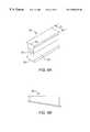
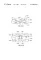
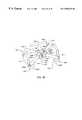
- a conventional implant device disposed between neighboring vertebraeis depicted in FIGS. 1 and 2.
- the implant devicecontains a pair of engaging elements 20 that typically contain threading 10 to engage the vertebrae.
- a vertebral drillis typically inserted within the surgical wound to drill into the cortical endplate and remove fibrous and nuclear material.
- a vertebral tapmay then be used to cut threads into the ends of the neighboring vertebrae.
- the engaging elementstend to be relatively inflexible and substantially undeflectable.
- the engaging elementsare typically packed with bone graft to facilitate a spinal fusion.
- the implant devicetend to not maintain the “lordosis” or natural curvature of the lower lumbar spine.
- the implant devicecontains parallel engaging sides 12 and 13 to contact vertebra 15 . It is typically required that the engaging sides be parallel to prevent the fusion cage from slipping from the intervertebral space.
- the parallel configuration of the fusion cagetends to alter the lordosis of the spine. Such a loss of lordosis may result in an increased risk to other intervertebral discs located adjacent to the fusion level that may degenerate due to the altered force transmission in the spine.
- FIG. 2depicts a front view of the engaging elements 20 of the implant device.
- the engaging elementsare substantially cylindrical and the region of contact between an engaging element and a vertebra is defined by arcuate portion 22 .
- the cylindrical geometry of the engaging elementstends to provide a relatively small area of contact between the fusion cage and the vertebrae.
- the weight of the spinecreates pressure on the vertebrae that is concentrated proximate the arcuate portions. Subsidence or deformation of the cortical layer of the vertebrae tends to result.
- U.S. Pat. No. 5,522,899 to Michelsonrelates to a spinal implant for placement into the spinal disc space to stabilize the spine and participate in a vertebra to vertebra bony fusion.
- U.S. Pat. No. 5,489,308 to Kuslich et al.relates to an implant for use in spinal stabilization that includes a cylindrical body having external threading and radially disposed openings positioned to chip bone into an interior portion of the body when the implant is installed.
- a spinal implantis provided that largely eliminates or reduces the aforementioned disadvantages of conventional implant devices.
- An embodiment of the inventionrelates to a fusion device for facilitating an interbody fusion between neighboring vertebrae of a human spine.
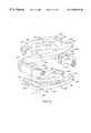
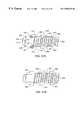
- the fusion devicepreferably includes a pair of sides or engaging plates for engaging the vertebrae and an alignment device disposed between the engaging plates for separating the engaging plates to maintain the engaging plates in lordotic alignment.
- the alignment deviceis preferably adapted to adjust the height between the engaging plates to customize the fusion device to a particular patient.
- the height of the fusion devicepreferably varies along the length of the device such that the height proximate an anterior end of the device differs from the height proximate a posterior end of the device.
- the engaging platesare preferably substantially planar so as to inhibit subsidence of the vertebrae.
- the engaging platesmay contain protrusions extending from their outer faces for enhancing an engagement between the vertebra and the engaging plate.
- the protrusionsmay be adapted to extend into the vertebra.
- the engaging platespreferably include a plurality of openings to allow bone growth to occur through the engaging plates.
- the openings in the face of the engaging platespreferably have a total area that is between about 60 percent and about 80 percent of a total surface area of the face (including the area of the openings).
- the fusion devicemay include a retaining plate proximate the posterior end that serves as a backing against which bone graft may be packed between the engaging plates.
- the fusion devicemay also include a removable end cap proximate the anterior end for maintaining bone graft between the engaging plates.
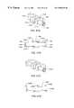
- the alignment deviceincludes a first strut and a second strut that each extend between the engaging plates to define the height therebetween.
- the fusion devicepreferably includes a first side and a second side opposite the first side.
- the first strutpreferably runs from the anterior end to the posterior end along a location proximate the first side
- the second strutpreferably runs from the anterior end to the posterior end along a location proximate the second side.
- the engaging platespreferably include a pair of slots sized to receive ends of the struts.
- the slotsmay have a substantially dovetail-shaped cross-section that is conformed to the shape of the ends.
- Each slotis preferably tapered such that its width narrows in a direction from the anterior end to the posterior end whereby the width of the slot proximate the posterior end is less than the width of the end of the strut.
- the ends of the strutspreferably have a lateral width that tapers in substantially the same manner as the slots such that a locking taper engagement is formable between the slots and the ends of the struts.
- each strutpreferably varies along the length of the strut such that the height between the engaging plates differs between the anterior end and the posterior end to allow the lordosis of the spine to be maintained.
- the first and second strutsmay have differing heights to cause the height of the fusion device to vary along the device from the first side to the second side to correct for a lateral deviation in the spinal column.
- Each of the strutsmay include a hinge to allow an upper member of the strut to pivot with respect to a lower member of the strut.
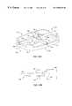
- the engaging platesinclude slots and the fusion device further includes a pair of pins disposed within the slots.
- Each engaging platepreferably includes a rib extending in a substantially perpendicular direction from its face.
- the slot for receiving the pinsis preferably disposed on the rib.
- the pinsare preferably substantially elongated and may extend in a direction from the first side to the second side.
- the fusion devicepreferably further includes a rotatable connector engaging the pins. Rotation of the connector preferably causes movement of the pins relative to one another to alter the height of the fusion device to create a desired lordotic alignment.
- the connectoris preferably adapted to move axially between the engaging plates and may contain a retaining ring for contacting an engaging plate to limit movement of the connector through the fusion device.
- the connectorpreferably moves axially between the engaging plates in a direction from the anterior end to the posterior end, thereby moving the first pin toward the anterior end and the second pin toward the posterior end to increase the height between the engaging plates.
- the connectormay be a screw having a threaded portion.
- the first pinmay include a threaded opening for receiving a threaded portion of the connector.
- the second pinmay be connected to an unthreaded portion of the connector.
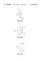
- the pinspreferably include a receiving section and an end.
- the ends of the pinsare preferably sized to fit within the slots in the ribs of the engaging plates.
- the receiving sectionmay have a width greater than that of the ends of the pins and preferably contains an opening for receiving the connector.
- One engaging platepreferably includes a first slot that may terminate in an end that extends in a diverging direction from an end of another slot contained on the other engaging plate. Movement of one of the pins preferably draws the ends of the slots together to alter the amount of separation between the engaging plates. The movement of the pins relative to one another preferably alters the height proximate the anterior end at a faster rate than the height proximate the posterior end is altered to achieve a desired lordotic alignment.
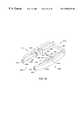
- the fusion devicecontains a load-sharing member to promote a spinal fusion.
- the load-sharing membermay be axially disposed within the struts.
- the load-sharing memberis preferably substantially deflectable to allow movement of one of the engaging plates when a compressive force is exerted on the engaging plates.
- a predetermined spacingpreferably exists between the upper and lower members.
- Application of a compressive force onto the engaging platespreferably deflects the load-sharing member and decreases the predetermined spacing between the members, thereby decreasing the height of the strut.
- the deflection of the load-sharing memberpreferably imparts stress to bone graft proximate the engaging plates to promote the development and growth of bone in accordance with Wolff's law.
- the load-sharing membermay be a pin having a circular cross-section and preferably is disposed in a bore extending axially through the strut.
- the borepreferably has a greater width than that of the load-sharing member to provide space for deflection of the load-sharing member.
- the load-sharing membermay serve as a hinge-pin about which the upper member of the strut pivots with respect to the lower member of the strut.
- the fusion devicepreferably further includes a connector for engaging the load-sharing member to impart force to the load-sharing member to cause it to deflect.
- the strutmay include a threaded opening in its end for receiving the connector.
- the predetermined spacing between the upper and lower membersmay be set to a desired length by altering the position of the connector in the opening in the end of the strut.
- the load-sharing membermay include an indention having a substantially planar surface to provide a site for engagement with the connector.
- the connectorpreferably engages the load-sharing member at a fulcrum point located at a predetermined horizontal distance from a support location where the lower member of the strut contacts the load-sharing member.
- the material properties of the load-sharing member and the distance between the fulcrum point and the support locationare preferably controlled such that the modulus of elasticity across the strut is substantially equal to the modulus of elasticity of bone.
- the fusion devicemay include a bracket assembly separating the engaging plates and supporting the alignment device.
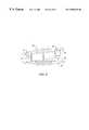
- the alignment devicemay include at least one screw coupled to at least one cam block.
- screwrefers generally to any elongated member having external threading.
- the cam blockmay include an opening through which the cam block is coupled to the screw. An inner surface of the opening may include threading that is complementary to the threading at an end of the screw.
- the threading of the screw and the threading of the cam blockmay form an engagement such that rotation of the screw in a first angular direction causes the cam block to move in a first lateral direction and such that rotation of the screw in an angular direction opposite the first angular direction causes the cam block to move in a lateral direction opposite the first lateral direction.
- the inner face of each of the engaging platesmay include sloped tracks.
- the cam blockmay include an upper surface and a lower surface.
- the surfaces of the cam blockmay be beveled or sloped to correspond to the slope of the tracks, such that the cam block fits into the tracks in the inner surfaces of the engaging plates.
- the surfaces of the cam block and the tracks in the inner faces of the engaging platesmay be configured such that movement of the cam block toward the exterior of the fusion device increases the height between the engaging plates and such that movement of the cam block toward the interior of the fusion device decreases the height between the engaging plates.
- the surfaces of the cam block and the tracks in the inner faces of the engaging platesmay be configured such that movement of the cam block toward the exterior of the fusion device decreases the height between the engaging plates and such that movement of the cam block toward the interior of the fusion device increases the height between the engaging plates.
- the fusion devicemay include cam blocks and tracks in the engaging plates incorporating each of the above mentioned design elements.
- the alignment devicemay include a single screw coupled to a single cam block.
- the alignment devicemay include a pair of screws, each of which is coupled to a single cam block.
- the screwsmay be situated such that a first screw is substantially parallel to and substantially adjacent a first edge of the fusion device.
- a second screwmay be situated substantially parallel to and substantially adjacent a second edge of the fusion device opposite the first edge.
- the first screwmay be substantially parallel to and substantially adjacent a first edge of the fusion device
- the second screwmay be substantially parallel to and substantially adjacent a second edge of the fusion device adjacent to the first edge.
- the alignment devicemay include three screws, each of which is coupled to a single cam block, such that a first screw is substantially parallel to and substantially adjacent a first edge of the fusion device.
- a second screwmay then be situated substantially parallel to and substantially adjacent a second edge of the fusion device opposite the first edge, and a third screw may be situated substantially parallel to and substantially adjacent a third edge located substantially perpendicular to and substantially adjacent the first edge and the second edge.
- the first screwmay be substantially parallel to and substantially adjacent a first edge of the fusion device
- the second screwmay be substantially parallel to and substantially adjacent a second edge of the fusion device
- the third screwmay be substantially parallel to and substantially between the first and the second screws.
- the alignment devicemay include at least one screw coupled to a cam block as previously described, and the inner face of each of the engaging plates may include sloped tracks as previously described. A tip of each of the screws may be substantially unthreaded.
- the alignment devicemay further include a stationary block positioned between the engaging plates. The stationary block may include openings into which the unthreaded tip of each of the screws may be inserted. The stationary block may support each of the screws and preserve the engagement between the screws and the cam blocks during use.
- the alignment devicemay include two screws, each of which is coupled to a cam block.
- the screwsmay be aligned such that the screws are positioned at an angle with respect to one another.
- the screwsmay be aligned such that the screws share a common axis of rotation.
- Two screwsare said to share a “common axis of rotation” if the spatial relation of the longitudinal axes of rotation of the two screws is such that the longitudinal axis about which a first screw may be rotated and the longitudinal axis about which a second screw may be rotated are defined by the same line, irrespective of the physical dimensions (e.g., the diameters) of the screws or the longitudinal separation between the screws.
- the alignment devicemay include three screws, each of which is coupled to a cam block.
- a first screwmay share a common axis of rotation with a second screw, and a third screw may be aligned substantially perpendicular to the first screw and the second screw.
- the first screwmay be oriented substantially perpendicular to the second screw, and the third screw may be oriented substantially at a first obtuse angle to the first screw and substantially at a second obtuse angle to the second screw.
- the first screwmay be oriented substantially at a first non-perpendicular angle to the second screw and substantially at a second non-perpendicular angle to the third screw.
- the first screwmay be oriented substantially parallel to the second screw, with the third screw situated between and substantially parallel to the first screw and the second screw.
- the alignment devicemay include four screws, each of which is coupled to a cam block.
- a first screwmay share a first common axis of rotation with a second screw, and a third screw may share a second common axis of rotation with a fourth screw.
- the first screw and the second screwmay be situated substantially parallel to and substantially adjacent a first edge of the fusion device.
- the third screw and the fourth screwmay be aligned substantially parallel to the first screw and the second screw and substantially adjacent an edge of the fusion device opposite the first edge.
- the first screwmay share a common axis of rotation with the second screw
- the third screwmay share a common axis of rotation with the fourth screw.
- the third screw and the fourth screwmay be aligned substantially perpendicular to the first screw and the second screw.
- the first screwmay share a common axis of rotation with the second screw and the third screw may share a common axis of rotation with the fourth screw.
- the third screw and the fourth screwmay be aligned at a substantially non-perpendicular angle to the first screw and the second screw.
- the fusion devicemay be configured such that its cross-section is substantially rectangular. The first screw and the second screw may then be aligned substantially along a first diagonal of the rectangle, and third screw and the fourth screw may then be aligned substantially along a second diagonal of the rectangle intersecting the first diagonal.
- the alignment devicemay include at least one screw configured to be coupled to a pair of cam blocks configured as described above.
- the inner face of each of the engaging platesmay include sloped tracks as previously described.
- the screwmay include a substantially unthreaded portion having a first diameter and a substantially threaded portion having a second diameter greater than the first diameter.
- the screwmay include a substantially unthreaded portion having a first diameter and a substantially threaded portion having a second diameter substantially equal to the first diameter.
- Each of the cam blocksmay include an opening through which the cam block is coupled to the screw.
- the inner surface of the opening in a first cam blockmay be substantially unthreaded.
- the inner surface of the opening in a second cam blockmay include threading that is complementary to the threading of the screw.
- the bracket assemblymay include projections into the interior of the fusion device and having inner surfaces having threading that is complementary to the threading of the screw. Rotation of the screw in a first angular direction may thus cause the screw to move in a first lateral direction with respect to the bracket assembly, and rotation of the screw in an angular direction opposite the first angular direction may thus cause the screw to move in a lateral direction opposite the first lateral direction.
- the unthreaded opening in the first cam blockmay be substantially similar in diameter to the diameter of the unthreaded portion of the screw.
- the unthreaded portion of the screwmay pass through the opening in the first cam block such that the screw is free to rotate within the opening in the first cam block.
- the screwmay further include a flange coupled to the screw at a first end of the screw adjacent the unthreaded portion of the screw.
- the first end of the screwmay include an indentation sized and shaped such that a tip of an adjusting tool may be inserted into the indentation.
- the adjusting toolmay be a screwdriver.
- the adjusting toolis an allen wrench. The adjusting tool may be used to rotate the screw.
- the diameter of the threaded portion of the screw and the diameter of the flangemay be sufficiently larger than the diameter of the opening in the first cam block such that coupling is maintained between the first cam block and the screw as the screw is rotated (i.e., the screw remains inserted in the opening through the first cam block) and such that the first cam block is constrained to move laterally in the same direction as the screw when the screw is rotated.
- the threading of the screw and the threading of the second cam blockmay form an engagement between the second cam block and the screw such that rotation of the screw causes the second cam block to move in a lateral direction opposite the direction of lateral motion of the screw.
- the alignment devicemay include a single screw coupled to a pair of cam blocks and situated substantially parallel to and substantially adjacent an edge of the fusion device.
- the alignment devicemay include a pair of screws that are each coupled to a pair of cam blocks.
- the screwsmay be situated such that a first screw is substantially parallel to and substantially adjacent a first edge of the fusion device.
- a second screwmay be situated substantially parallel to and substantially adjacent a second edge of the fusion device opposite the first edge.
- the first screwmay be situated substantially parallel to and substantially adjacent a first edge of the fusion device and the second screw may be situated substantially parallel to and substantially adjacent a second edge of the fusion device adjacent to the first edge.
- the alignment devicemay include three screws, each of the screws being coupled to a pair of cam blocks, such that a first screw is substantially parallel to and substantially adjacent a first edge of the fusion device.
- a second screwmay then be situated e substantially parallel to and substantially adjacent a second edge of the fusion device opposite the first edge, and a third screw may be situated substantially parallel to and substantially adjacent a third edge of the fusion device located substantially perpendicular to the first edge and the second edge.
- the screw in the alignment devicemay be a turnbuckle.
- turnbucklerefers to a screw having external threading in a first direction at a first end and external threading in a direction opposite the first direction at a second end opposite the first end.
- the turnbucklemay be coupled to a pair of cam blocks via threaded openings in the cam blocks.
- An inner surface of each of the openingsmay include threading that is complementary to the threading at one of the ends of the turnbuckle.
- the threading of the turnbuckle and the threading of the cam blocksmay form an engagement such that rotation of the turnbuckle in a first direction causes the cam blocks to move away from each other and such that rotation of the turnbuckle in a direction opposite the first direction causes the cam blocks to move toward each other.
- the inner face of each of the engaging platesmay include sloped tracks as previously described.
- At least one end of the turnbucklemay include an indentation sized and shaped such that a tip of an adjusting tool may be inserted into the indentation.
- the adjusting toolmay be a screwdriver.
- the adjusting toolis an allen wrench. The adjusting tool may be used to rotate the turnbuckle.
- the turnbucklemay include a middle portion disposed between the first end and the second end and having a thickness greater than a thickness of the first end and a thickness of the second end.
- the bracket assemblymay include lateral projections into the interior of the fusion device.
- the middle portion of the turnbucklemay be configured to fit between the lateral projections from the bracket assembly.
- the lateral projectionsmay include openings of a size sufficient to allow the ends of the turnbuckle to pass through without allowing the middle portion to pass through, thus maintaining the turnbuckle in the bracket assembly.
- the alignment devicemay include a single turnbuckle coupled to a pair of cam blocks and situated substantially parallel to and substantially adjacent an edge,of the fusion device.
- the alignment devicemay include a pair of turnbuckles that are each coupled to a pair of cam blocks.
- the turnbucklesmay be situated such that a first turnbuckle is substantially parallel to and substantially adjacent a first edge of the fusion device.
- a second turnbucklemay be situated substantially parallel to and substantially adjacent a second edge of the fusion device opposite the first edge.
- the first turnbucklemay be substantially parallel to and substantially adjacent a first edge of the fusion device
- the second turnbucklemay be substantially parallel to and substantially adjacent a second edge of the fusion device adjacent to the first edge.
- the alignment devicemay include three turnbuckles that are each coupled to a pair of cam blocks, such that a first turnbuckle is substantially parallel to and substantially adjacent a first edge of the fusion device.
- a second turnbucklemay then be situated substantially parallel to and substantially adjacent a second edge of the fusion device opposite the first edge, and a third turnbuckle may be situated substantially parallel to and substantially adjacent a third edge of the fusion device located substantially perpendicular to the first edge and the second edge.
- An advantage of the inventionrelates to an intervertebral body fusion device that substantially maintains the natural lordosis of the human spine.
- Another advantage of the inventionrelates to an intervertebral body fusion device adapted to correct a lateral deviation in the spinal column.
- Anther advantage of the inventionrelates to an intervertebral body fusion device that substantially maintains the natural lordosis of the human spine while simultaneously being adapted to correct a lateral deviation in the spinal column.
- FIG. 1depicts a conventional intervertebral body fusion implant positioned between neighboring vertebrae
- FIG. 2depicts another conventional intervertebral body fusion implant that includes a pair of cylindrical members positioned between neighboring vertebrae;
- FIG. 3depicts a top view of a fusion device located on a vertebral body
- FIG. 4 adepicts a cross-sectional view of the fusion device of FIG. 3 taken along plane I;
- FIG. 4 bdepicts a cross-sectional view of the fusion of FIG. 3 device taken along plane I wherein the fusion device contains bone graft and has been adjusted to maintain a substantially natural lordosis;
- FIG. 5depicts a front view of a fusion device
- FIG. 6 adepicts a perspective view of a strut
- FIG. 6 bdepicts a side view of a tapered strut
- FIG. 7depicts a top view of a fusion device
- FIG. 8depicts a front view of a pair of engaging plates
- FIG. 9depicts a front view of a fusion device having pivotable struts
- FIG. 10depicts a top view of a fusion device containing a connector
- FIG. 11depicts an anterior view of a fusion device having a connector and cam pins
- FIG. 12depicts a cross-sectional view taken along plane III of FIG. 11 of the fusion device in a lowered position
- FIG. 13depicts a cross-sectional view taken along plane III of FIG. 11 of the fusion device in a raised position
- FIG. 14depicts a cross-sectional view taken along plane IV of FIG. 11 of the fusion device in a lowered position
- FIG. 15depicts a cross-sectional view taken along plane IV of FIG. 11 of the fusion device in a raised position
- FIG. 16depicts a side view of a fusion device disposed between vertebrae
- FIG. 17depicts a top view of a strut having a tapered end
- FIG. 18depicts a cross-sectional view taken along plane V of FIG. 17 of the strut in an unloaded position
- FIG. 19depicts a cross-sectional view taken along plane V of FIG. 17 of the strut in a loaded position
- FIG. 20depicts a top view of a fusion device located on a vertebral body
- FIG. 21depicts a cross-sectional view of the fusion device taken along plane VI of FIG. 3;
- FIG. 22depicts a top view of a conventional fusion cage having a pair of cylindrical elements disposed on a vertebra
- FIG. 23depicts a side view of one of the cylindrical elements in FIG. 22 disposed between neighboring vertebrae;
- FIG. 24depicts a front view of the cylindrical element in FIG. 23;
- FIG. 25depicts a perspective view of a fusion device in the lowered position, the fusion device including a pair of turnbuckles oriented perpendicular to the anterior and posterior edges of the fusion device;
- FIG. 26depicts a perspective view of the fusion device of FIG. 25 in the raised position
- FIG. 27depicts an exploded view of the fusion device of FIG. 25;
- FIG. 28depicts a perspective view of a bracket assembly of the fusion device of FIG. 25;
- FIG. 29 adepicts a perspective view of the end of the bracket assembly of FIG. 25;
- FIG. 29 bdepicts a perspective view of a cam block of the fusion device of FIG. 25;
- FIG. 29 cdepicts a side view of the cam block of FIG. 29 b;
- FIG. 30 adepicts a cutaway view of the fusion device of FIG. 25 in a lowered position
- FIG. 30 bdepicts a cutaway view of the fusion device of FIG. 25 in a raised position
- FIG. 31 adepicts a cutaway view of an alternative configuration of the fusion device of FIG. 25 in a lowered position
- FIG. 31 bdepicts a cutaway view of an alternative configuration of the fusion device of FIG. 25 in a raised position
- FIG. 32 adepicts a top view of the alignment device of FIG. 25 in use
- FIG. 32 adepicts a front view of the alignment device of FIG. 25 in use in a lowered position
- FIG. 32 cdepicts a front view of the alignment device of FIG. 25 in use in a raised position
- FIG. 33depicts an exploded view of a fusion device including a pair of turnbuckles oriented parallel to the anterior and posterior edges of the fusion device;
- FIG. 34depicts a perspective view of the bracket assembly of the fusion device of FIG. 32;
- FIG. 35depicts an exploded view of a fusion device including a pair of screws, each of which is threaded through a pair of cam blocks,
- FIG. 36depicts a perspective view of the alternative bracket assembly of the fusion device of FIG. 34;
- FIG. 37 adepicts a cross-sectional view of the screws and cam blocks of FIGS. 35-36 in use in a first position
- FIG. 37 bdepicts a cross-sectional view of the screws and cam blocks of FIGS. 35-36 in use in a second position
- FIG. 38depicts an exploded view of a fusion device including three turnbuckles
- FIG. 39depicts a perspective view of the bracket assembly of the fusion device of FIG. 38;
- FIG. 40depicts an exploded view of a fusion device including three substantially parallel screws
- FIG. 41depicts a perspective view of the bracket assembly of the fusion device of FIG. 40;
- FIG. 42depicts an exploded view of a fusion device including three non-parallel screws
- FIG. 43 adepicts a perspective view of the bracket assembly of the fusion device of FIG. 42;
- FIG. 43 bdepicts a cross-sectional view of a screw, a cam block, and the stationary block of FIG. 42;
- FIG. 44depicts an exploded view of a fusion device including four screws oriented as two parallel pairs
- FIG. 45depicts a perspective view of the bracket assembly of the fusion device of FIG. 42;
- FIG. 46depicts an exploded view of a fusion device including four screws oriented in a “+” configuration
- FIG. 47depicts a perspective view of the bracket assembly of the fusion device of FIG. 46;
- FIG. 48depicts an exploded view of a fusion device including four screws oriented in an “x” configuration
- FIG. 49depicts a perspective view of the bracket assembly of the fusion device of FIG. 48;
- FIG. 50 adepicts a perspective view of a fusion device including one screw and at least one cam block in a lowered position
- FIG. 50 bdepicts a perspective view of the fusion device of FIG. 50 a in a raised position
- FIG. 50 cdepicts an exploded view of the fusion device of FIG. 50 a;
- FIG. 51 adepicts a cutaway view of an embodiment of a bracket assembly of the fusion device FIG. 50 a;
- FIG. 51 bdepicts a cross-sectional view of a turnbuckle of the bracket assembly of FIG. 51 a;
- FIG. 51 cdepicts a cutaway view of an alternative embodiment of a bracket assembly of the fusion device of FIG. 50 a;
- FIG. 51 ddepicts a cross-sectional view of a turnbuckle of the bracket assembly of FIG. 51 c;
- FIG. 52 adepicts a top view of the fusion device of FIG. 50 a in use
- FIG. 52 bdepicts a side view of a pair of the fusion devices of FIG. 50 a in use.
- FIGS. 3-5A preferred embodiment of an interbody fusion implant device 10 for facilitating the formation of a spinal fusion is depicted in FIGS. 3-5.
- a top view of the fusion deviceis depicted in FIG. 3 .
- Fusion device 10preferably includes a pair of sides or engaging plates 12 and 14 for engaging vertebral bodies 16 and 18 .
- the engaging platesmay contain curved edges such that the outer face 15 of the plates conforms to the shape of the cross-section of the vertebral bodies as shown in FIG. 3 .
- the fusion devicehas a height 20 defined by the vertical distance between the outer faces 15 of the engaging plates 12 and 14 .
- the height 20 of the fusion deviceis preferably adjustable and may vary along the fusion device between anterior end 22 and posterior end 24 to maintain the natural lordosis of the spine.
- Height 20may also vary along device 10 from first side 26 to second side 28 to correct for a lateral deviation in the spine as may occur in scoliosis.
- Fusion device 10preferably further includes an alignment device for adjusting the height 20 so that the natural lordosis of the spine is substantially maintained after the fusion device is implanted.
- the alignment devicemay be used to adjust the height between the engaging plates proximate the anterior end and independently adjust the height between the engaging plates proximate the posterior end.
- a spinal fusionis typically employed to eliminate pain caused by the motion of degenerative disk material.
- fusion device 10becomes permanently fixed within the disc space.
- the fusion deviceis preferably packed with bone graft 40 to promote the growth of bone through and around the fusion device.
- bone graftmay be packed between engaging plates 12 and 14 prior to, subsequent to, or during implantation of the fusion device.
- Bone substitute materialthat is well known to those skilled in the art may be used instead of bone graft.
- a bone harvester kitcommercially available from Spine-Tech, Inc. located in Minneapolis, Minn., may be used to inject bone graft between the engaging plates.
- the pamphlet entitled “Bone Harvester: Minimally Invasive Bone Harvesting Kit”(available from Spine-Tech, Inc.) details the use of the bone harvesting kit.
- the faces 15 of engaging plates 12 and 14contain a plurality of openings 34 disposed therein to allow bone development and growth through the engaging plates 12 and 14 and between fusion device 10 and neighboring vertebrae 16 and 18 .
- the openings 34have a combined area that is greater than about 50 percent of the area of face 15 (including the area of the openings 34 ), more preferably between about 60 percent and about 80 percent of the area of face 15 , and more preferably still about 70 percent or more of the area of face 15 .
- the fusion devicemay contain a retaining plate 36 proximate posterior end 24 to provide a backing against which bone graft may be packed and to maintain the bone graft between the engaging plates.
- Retaining plate 36may be substantially planar and may contain openings to allow bone ingrowth therethrough.
- a removable endcap 25may be positioned proximate anterior end 22 to contain bone graft within the fusion device and to prevent the migration of bone graft outside the engaging plates.
- the endcap 25may contain one or more openings for allowing bone ingrowth between a vertebral body and bone graft contained between the engaging plates.
- Endcap 25is preferably made of a plastic material such as polyethylene that tends to be non-irritating and non-abrasive to the surrounding tissues.
- FIG. 4 ashows the relative position of engaging plates 12 and 14 before height 20 has been adjusted with an alignment device to achieve a substantially natural lordosis.
- FIG. 4 bshows the relative position of the plates after height 20 has been adjusted and bone graft 40 has been packed between the engaging plates.
- FIG. 4 bshows that height 20 is greater in the vicinity of anterior end 22 as compared to posterior end 24 to maintain the natural lordosis of the spinal column.
- the faces 15 of the engaging plates 12 and 14are preferably planar to provide a relatively large contact area between the engaging plates and the neighboring vertebrae.
- the engaging platesmay be non-planar.
- the engaging platesalso preferably contain a plurality of spikes or protrusions 38 extending from the face 15 for enhancing an engagement between the vertebra and the engaging plate.
- the protrusionsmay extend into the vertebra to prevent the fusion device from moving out of the disc space.
- the engaging platesare preferably constructed of titanium or a titanium alloy, although it is to be understood that other materials (e.g., ceramics, metals, carbon composites) may be used.
- the alignment deviceincludes a first strut 30 and a second strut 32 that each extend between engaging plates 12 and 13 along the length of the fusion device from anterior end 22 to posterior end 24 .
- a “strut”is taken to mean any support member disposed between the engaging plates to separate the engaging plates.
- Strut 30preferably extends along the fusion device proximate first side 26 .
- Strut 32is preferably substantially parallel to strut 30 and may extend along the fusion device proximate second side 28 .
- the struts 30 and 32serve to create a predetermined spacing between the engaging plates. The predetermined spacing is preferably such that the height 20 is approximately equal to the height of the disc material that formerly occupied the disc space between the vertebral bodies.
- the strutmay have an “I-beam” shape and preferably includes a pair of ends 50 .
- the ends 50may have a lateral width 51 that is greater than that of the sides 53 .
- the endspreferably have a “dovetail” shaped cross-section as shown in FIG. 6 a .
- the engaging platespreferably contain elongated slots 60 (shown in FIGS. 7 and 8) sized to receive ends 50 of the first and second struts.
- the slots 60preferably have a complementary dovetail shape as depicted in FIG. 8 that conforms to the shape of the end 50 .
- the strutsmay be connected to the engaging plates by sliding ends 50 into the slots 60 in a direction from anterior end 22 to posterior end 24 or vice versa.
- the slotsare tapered such that their width narrows in a direction from the anterior end to the posterior end as shown in FIG. 7 .
- the ends 50may be tapered (as shown in FIG. 17) such that the lateral width 51 narrows along the length of the strut.
- the taper of the lateral width of the strutpreferably matches that of slot 60 .
- the width of the slot proximate the anterior endis preferably sized to allow the strut end to be slid into the slot.
- the width of the slot proximate the posterior endis preferably less than the lateral width 51 of the narrowest portion of end 50 .
- the tapering of the slotspreferably allows a “locking taper engagement” of the strut ends within the slots.
- a “locking taper engagement”is taken to mean a fixable interference fit formed between end 50 and slot 60 whereby the strut resists dislodgment when force is imparted to the fusion device from the adjacent vertebrae.
- the slotsmay be tapered such that the width of the slots narrows in a direction from the posterior end to the anterior end.
- the first and second strutspreferably each have a predetermined height that defines the height of the fusion device.
- the engaging plates 12 and 14are preferably adapted to receive struts of various heights to allow height 20 to be varied to fit the needs of the patient.
- a side view of a tapered strutis depicted in FIG. 6 b .
- the tapered strutpreferably has a height that varies along its length. In this manner, the tapered strut is positionable between the engaging plates 12 and 14 to cause height 20 to decrease in a direction from anterior end 22 to posterior end 24 whereby the natural lordosis of the human spine is maintained by the fusion device.
- the degree of taper of the strutcorresponds to a desired lordosis and may vary depending upon the size of the patient.
- the first and second strutshave differing heights to cause height 20 to vary between first end 14 and second end 16 .
- the fusion devicemay be used to correct a lateral deviation in the spinal column as may occur in scoliosis.
- a front view of a fusion device containing struts having different heightsis depicted in FIG. 9 .
- Each of the strutspreferably contains a hinge pin 70 to allow an upper member 72 of the strut to pivot with respect to a lower member 74 of the strut. In this manner, the struts may be pivoted as shown in FIG. 9 such that the ends of the struts are properly aligned with the slots of the engaging plates when a height difference exists between the first and second struts.
- a discectomyis preferably performed from an anterior approach. All cartilage and soft tissue are preferably removed from the vertebral endplate as would normally be done for placement of a femoral strut graft. Such a procedure is well within the knowledge of a skilled practitioner of the art.
- the engaging platesmay be deployed in the disc space between the adjacent vertebrae.
- a distraction forcemay be applied to the engaging plates using a laminae spreader or similar device to force the vertebrae to a selected height and lordotic alignment.
- the use of a laminae spreaderis well known to those skilled in the art.
- the proper heights for the first and second strutsmay be determined beforehand using x-ray techniques in which the posterior and anterior portions of the intervertebral disc space are examined.
- each strutmay be pivoted about hinge pin 70 prior to insertion so that ends 50 are properly aligned for placement into grooves 60 .
- Bone graft materialis preferably inserted through the anterior end and packed between the engaging plates. Retaining plate 36 preferably prevents the bone graft material from passing through the fusion device during packing. Endcap 25 may then be placed onto the anterior end.
- the alignment deviceincludes a connector 80 for adjusting the height 20 of the plates to achieve a desired lordotic alignment.
- FIG. 10depicts a top view of the fusion device.
- Connector 80is preferably a drive screw that is rotatable to adjust height 20 .
- Connector 80preferably extends between engaging plates 12 and 14 and may be adapted to move axially through the fusion device in a direction from anterior end 22 to posterior end 24 .
- the engaging platesmay contain elongated openings 82 for allowing bone growth through the faces 15 of the plates.
- FIG. 11depicts a front (anterior) view of the fusion device in a raised position.
- the engaging platesinclude ribs 84 and 85 that may extend substantially perpendicularly from face 15 .
- a cross-sectional view taken along plane III of FIG. 11is depicted in each of FIG. 12 and FIG. 13 .
- FIG. 12depicts rib 84 and cam pins 86 and 88 in section with the fusion device in a “lowered position” (i.e., unadjusted for lordotic alignment).
- FIG. 13depicts the rib and cam pins in section with the fusion device in the “raised position” (i.e., adjusted for lordotic alignment).
- “cam pin”is taken to mean any connecting element capable of extending from the connector into the slots 90 and 92 .
- Each of the cam pinsmay be intersected by an imaginary longitudinal axis 91 axially extending through the fusion device.
- Rib 84preferably contains a slot 90 having a first end and a second end. The ends of slot 90 preferably terminate in a direction below axis 91 . The first end of slot 90 preferably extends downwardly substantially toward either the face of engaging plate 14 or the anterior end. The second end of slot 90 preferably extends downwardly substantially toward either the face of engaging plate 14 or the posterior end. Rib 85 preferably contains a slot 92 having a pair of ends that extend in diverging directions from the slot ends of rib 84 . The ends of slot 92 preferably terminate in a direction above axis 91 . The first end of slot 92 preferably extends upwardly substantially toward either the face of engaging plate 12 or the anterior end.
- the second end of slot 90preferably extends upwardly substantially toward either the face of engaging plate 12 or the posterior end.
- the engaging platesare preferably connected together with cam pins 86 and 88 , which preferably have ends sized to fit within slots 90 and 92 .
- the cam pinspreferably are disposed through the fusion device in a direction from the first side to the second side.
- Pins 86 and 88preferably contain a receiving section 87 having an opening for receiving connector 80 .
- Receiving section 87may have a greater width (e.g., diameter) than the ends of pins 86 and 88 disposed in slots 90 and 92 .
- FIG. 14 and FIG. 15each depict a cross-sectional view of the fusion device taken along plane IV of FIG. 11 .
- FIG. 14depicts the connector and cam pins in section with the fusion device in the lowered position.
- FIG. 15depicts the connector and the cam pins in section with the fusion device in the raised position.
- connector 80contains a threaded portion 94 and an unthreaded portion 96 .
- Pin 86is preferably connected to the threaded portion and pin 88 is preferably connected to the unthreaded portion.
- a torque delivered to the connectoris converted into a separation force between the cam pins.
- Rotating the connector in a counterclockwise directionpreferably moves the connector in a direction from the anterior end to the posterior end.
- Pin 88is preferably attached to the connector and preferably moves in the same manner as the connector.
- Pin 86preferably contains an opening having complementary threading to that of the connector.
- Pin 86preferably moves toward the anterior end in a direction opposite the motion of the connector to increase the separation between pin 88 and pin 86 .
- the ends of the pinspreferably move along the angled portions of the slots 90 and 92 , causing the ends of the slots to be drawn together. In this manner, the separation between the engaging plates is increased.
- the connectormay be rotated in a counterclockwise direction to move the connector in a direction from the posterior end to the anterior end, thereby decreasing height 20 .
- Connector 80is preferably operable to separate the engaging plates (hence the vertebrae) and create a desired lordotic alignment.
- the distance that the engaging plates are separated per unit torque applied to the connectorwill tend to depend upon the angle of the slots 90 and 92 .
- the slotsare preferably angled such that the height 20 proximate the anterior end changes at a greater rate than the i height 20 proximate the posterior end when the connector is adjusted to alter the distance between the plates. In this manner, a desired lordotic alignment may be achieved.
- the fusion deviceis operable in a semi-raised position that is intermediate the raised and lowered positions depicted in FIGS. 12-15.
- the connectoris preferably rotated to a selected degree to achieve a preferred height 20 proximate the anterior and posterior ends to suit the particular patient.
- the angle of the slots 90 and 92may vary among patients and is preferably selected to achieve a desired lordotic alignment.
- the connectormay include a retaining ring 98 for contacting one or both of the engaging plates to limit the degree to which the connector can move through the fusion device.
- FIG. 16depicts a side view of an alternate embodiment of the fusion device installed between neighboring vertebrae.
- Pin 86may be located on the unthreaded portion of the shank adjacent to the head of connector 80 .
- Pin 88may be located on threaded portion 94 of the shank of connector 80 .
- Rib 84preferably includes a first slot 100 that is angled diagonally upward from axis 91 in a direction substantially toward either the face of engaging plate 12 or the anterior end 22 .
- Rib 84preferably also includes a second slot 102 that is angled diagonally upward from axis 91 in a direction substantially toward either the face of engaging plate 12 or the posterior end 24 .
- Rib 85preferably includes a first slot 104 that is angled diagonally downward from axis 91 in a direction substantially toward either the face of engaging plate 14 or the anterior end 22 . Rib 85 preferably also includes a second slot 106 that is angled diagonally downward from axis 91 in a direction substantially toward either the face of engaging plate 14 or the posterior end 24 .
- the connectormay be rotated to cause the cam pins to be moved in a direction toward one another.
- Pin 86preferably moves with the connector in a direction from the anterior end to the posterior end to increase the separation between the engaging plates proximate the anterior end.
- Pin 88preferably contains a threaded opening for receiving the connector and may move in a direction toward the posterior end to increase the separation between the engaging plates proximate the posterior end.
- each of the pins 86 and 88contains a threaded opening for receiving the connector 80 .
- the connectormay be a “double-threaded” screw having two threaded portions for complementing the threaded openings of the pins 86 and 88 .
- Rotation of the screw in a first directionpreferably causes the pins to move toward one another to increase the separation between the engaging plates.
- Rotation of the screw in an opposite directionpreferably causes the pins to move away from one another to reduce the separation between the engaging plates.
- the alignment deviceincludes a load-sharing member to allow the engaging plates to move in response to a compressive force of predetermined magnitude.
- a compressive forceof predetermined magnitude.
- the load-sharing memberpreferably enables the fusion device to “share” compressive forces exerted onto the spinal column with the bone graft in the vicinity of the fusion device.
- the load-sharing memberpreferably is deflected upon receiving a predetermined force to cause the engaging plates to move, thereby shifting load from the fusion device to the bone graft proximate the fusion device. It is believed that providing a selected amount of stress to the bone graft in a such a manner will tend to result in a higher fusion rate as well as a stronger fusion mass.
- FIGS. 17-19An embodiment of the load-sharing fusion device is depicted in FIGS. 17-19.
- a top view of a strut 30 containing a load-sharing memberis depicted in FIG. 17 .
- FIGS. 18 and 19depict cross-sectional views of the strut taken along plane V of FIG. 17 .
- Load-sharing member 110is preferably disposed axially through the strut.
- the load-sharing membermay be contained in a bore extending into the strut.
- the borepreferably has a width (e.g., diameter) that is greater than that of the load-sharing member to allow sufficient space for the load-sharing member to be deflected.
- the boreis preferably disposed within lower member 74 .
- Portion 118 of the upper membermay substantially surround the bore and the load-sharing member, thereby allowing attachment of the upper and lower members.
- the load-sharing memberis a pin having a substantially circular cross-section. The pin preferably fits loosely within the bore such that its rotational freedom is maintained.
- the pinmay be hinge pin 70 about which the upper member 72 pivots with respect to the lower member 74 .
- the load-sharing memberpreferably contains an indention 114 forming a substantially planar surface about which the load-sharing member may be deflected.
- a connector 112preferably extends through an opening 116 in the end 50 of the strut.
- the connectorpreferably fixes the load-sharing member to the upper member 72 and may contact the load-sharing member at fulcrum point 126 , which is preferably located on the planar surface formed by indention 114 .
- Connector 122is preferably a set screw, and opening 116 preferably contains threading for engaging the set screw.
- FIG. 18depicts the strut in an “unloaded” position whereby a predetermined spacing 122 exists between upper member 72 and portion 120 of lower member 74 .
- the predetermined spacing 122may be adjusted by altering the location of connector 112 within opening 116 . For instance, the screw may be rotated through opening 116 to increase spacing 122 .
- the load-sharing memberpreferably remains substantially undeflected in the unloaded position.
- forceis preferably imparted from connector 112 to the load-sharing member at fulcrum point 126 .
- the compressive forceis preferably sufficient to cause deflection of the load-sharing member and movement of upper member 72 toward portion 120 of the lower member such that predetermined spacing 122 is decreased.
- the deflection of the load-sharing membermay force portion 118 of the upper member into a cavity 115 formed within the axial bore.
- the load-sharing memberis preferably deflected in a three point bending arrangement as shown in FIG. 19 .
- FIG. 19depicts the strut in the “loaded” position with the load-sharing member deflected.
- the predetermined spacing 22is preferably adjustable and may be adjusted to set the maximum strain that can be imparted to the load-sharing member.
- the upper member 72contacts portion 120 , thereby inhibiting further strain on the load-sharing member. In this manner, the maximum amount of strain on the load-sharing member can be limited to reduce the possibility that the member will experience fatigue failure.
- the load-sharing membermay be constructed of any of a variety of metals or alloys.
- the load-sharing memberis constructed of titanium or a titanium alloy.
- the material properties and cross-sectional area of the load-sharing memberare preferably controlled to allow a predetermined amount of stress to occur across the fusion device.
- the horizontal distance 124 or moment arm between fulcrum point 126 and support point 128 on the lower memberis preferably selected such that the fusion device has an “effective” modulus of elasticity in the vicinity of the modulus of elasticity of bone to facilitate bone development.
- the a“effective” modulus of elasticity of the fusion deviceis taken to mean the ratio of stress to strain across the fusion device in a direction along height 20 as the device moves from the unloaded position to the loaded position upon receiving a compressive force.
- “in the vicinity of the modulus of elasticity of bone”is taken to mean a Young's modulus between about 3 GPa and about 25 GPa.
- the effective modulus of the fusion deviceis between about 16 GPa and about 20 GPa.
- the stresses exerted onto the spinal columnare preferably shared by the fusion device and surrounding bone graft. As the spinal fusion develops, the proportion of stress experienced by the surrounding bone material preferably increases and the required load on the fusion device preferably decreases. After completion of the fusion, the fusion device preferably remains in the unloaded position during normal daily activity of the patient.
- FIG. 20depicts a top view of an embodiment of a fusion device of the present invention.
- FIG. 21depict a cross-sectional view of the fusion device taken along plane VI of FIG. 20 .
- Depicted in FIGS. 22-24is a conventional fusion cage such as that described in U.S. Pat. No. 4,961,740 to Ray et al. This patent is incorporated by reference as if fully set forth herein.
- the devices in FIGS. 20-24are sized for use in the L3-L4 disc space of an average size middle-aged female. Dimensions of the fusion devices are indicated in millimeters.
- the “effective contact area” between an engaging plate and a vertebral bodymay be calculated by subtracting the fenestration area, a (i.e., the combined area of the openings 34 intended for bone ingrowth), from the total contact area, A (the area of the face 15 including the area of the openings 34 ).
- the total contact area and the fenestration area of the fusion device in FIGS. 20 and 21is 581 mm 2 and 96 mm 2 , respectively. Therefore, the effective contact area between the engaging plate and the vertebra is 485 mm 2 .
- each of the cylindrical elements of the fusion cagehas a total contact area of 283.5 mm 2 and a fenestration area of 198.5 mm 2 . Therefore, the combined effective contact area of both of the cylindrical elements is 170 mm 2 . If the threads of the fusion cage penetrate into the vertebra a distance less than 3 mm per side, the contact area will be less than that calculated above.
- the maximum axial compressive forces in the lumbar spine resulting from everyday activitywere estimated to be 3200 N in a paper entitled “The BAKTM Interbody Fusion: An Alternative Solution” by Bagby et al. and available from Spine Tech, Inc. in Minneapolis Minn. (see page 3, bottom paragraph).
- the stress per unit areais calculated to be 18.8 N/mm 2 for the fusion cage depicted in FIGS. 22-24 as compared to 6.6 N/mm 2 for the fusion device depicted in FIG. 20 and FIG. 21 . It is believed that such a reduction in stress per unit area will result in a significant reduction in post surgical subsidence at the interface of the fusion device and vertebral body.
- the loss of disc heightis estimated to be about 1-3 mm at one month follow-up when conventional devices such as that depicted in FIGS. 22-24 are employed.
- FIGS. 25-27An alternate embodiment of an interbody fusion device is depicted in FIGS. 25-27.
- FIG. 25is a perspective view of the fusion device in a lowered position.
- FIG. 26is a perspective view of the fusion device in a raised position.
- FIG. 27is an exploded view of the fusion device.
- Fusion device 200includes a pair of engaging plates 202 and 204 for engaging adjacent vertebrae. Engaging plates 202 and 204 are preferably separated by bracket assembly 206 .
- Engaging plates 202 and 204 and bracket assembly 206may be formed of titanium, stainless steel, polymer, ceramic, composite material, or any other biocompatible material.
- “biocompatible material”is material not rejected by the body and/or not causing infection following implantation.
- engaging plates 202 and 204may contain a plurality of protrusions 216 from outer surfaces 203 for enhancing an engagement between the vertebrae and the engaging plates. In this manner, subsidence of the vertebrae may be substantially prevented as previously described.
- Outer surfaces 203are preferably substantially planar to provide a large contact area between the engaging plates and the vertebrae; alternately, outer surfaces 203 may be non-planar.
- Protrusions 216may extend into the vertebrae to prevent the fusion device from moving out of the disc space.
- Engaging plates 202 and 204may include a plurality of openings 218 to allow bone development and growth through the engaging plates and between fusion device 200 and the neighboring vertebrae.
- openings 218have a combined area that is greater than about 50% of the total area of outer surfaces 203 (including the area of openings 218 ). More preferably, openings 218 have a total area between 60% and 80% of the total area of outer surfaces 203 . More preferably still, openings 218 have a total area of 70% or more of the total area of outer surfaces 203 .
- Bracket assembly 206(depicted in perspective view in FIG. 28) preferably includes an alignment device for changing a height between engaging plates 202 and 204 .
- the alignment deviceincludes first turnbuckle 250 and second turnbuckle 270 positioned substantially parallel to and substantially adjacent first side edge 212 and second side edge 214 , respectively, and extending between anterior edge 208 and posterior edge 210 .
- Bracket assembly 206includes lateral projections 244 and 246 extending into the interior of the bracket assembly and supporting turnbuckles 250 and 270 , respectively.
- the turnbucklesinclude middle portions (e.g., middle portion 256 of turnbuckle 250 ) disposed between the ends of the turnbuckles and having a diameter greater than a diameter of the threaded portions.
- Lateral projection 244is sized such that middle portion 256 is retained within lateral projection 244 while turnbuckle 250 is free to rotate within lateral projection 244 .
- Ends 296 of bracket assembly 206may include arcuate grooves 297 which correspond to the curvature of turnbuckles 250 and 270 .
- Inner surface 209 (FIG. 27) of engaging plate 204 and the inner surface of engaging plate 202also may include arcuate grooves 228 and 240 (FIG. 27 ), respectively, which correspond to the curvature of turnbuckles 270 and 250 .
- first threaded portion 252 of first turnbuckle 250is preferably threaded in a first direction and second threaded portion 254 of first turnbuckle 250 is preferably threaded in a direction opposite the first direction.
- First threaded portion 272 of second turnbuckle 270is preferably threaded in a second direction and second threaded portion 274 of second turnbuckle 270 is preferably threaded in a direction opposite the second direction.
- First threaded portions 252 and 272may be threaded in the same direction or in opposite directions.
- First turnbuckle 250is preferably configured to be coupled to cam blocks 260 and 261 ;
- second turnbuckle 270is preferably configured to be coupled to cam blocks 280 and 281 .
- Cam block 260is preferably coupled to first turnbuckle 250 through opening 266 (FIG. 29 B). Opening 266 is preferably threaded complementarily to first portion 252 of first turnbuckle 250 .
- Cam blocks 261 , 280 , and 281are preferably similarly configured for coupling to turnbuckle portions 254 , 272 , and 274 , respectively.
- Cam block 260preferably includes upper surface 262 having a first slope and lower surface 264 having a second slope (FIG. 29 C); cam blocks 261 , 280 , and 281 are preferably similarly configured.
- the slopes of corresponding features on paired cam blockse.g., the slopes of upper surface 262 of cam block 260 and upper surface 263 of cam block 261 ) are preferably equivalent.
- the slopes of corresponding features on paired cam blocksmay differ.
- the slope of upper surface 262 of cam block 260need not be equivalent to the slope of lower surface 264 of cam block 260 .
- slope of upper surface 262 of cam block 260need not be equivalent to the slope of upper surface 282 of cam block 280 , to the slope of upper surface 283 of cam block 281 , or to the slopes of the lower surfaces of cam blocks 280 and 281 (not visible in FIG. 28 ).
- inner surface 209 of engaging plate 204preferably includes sloped tracks 220 , 222 , 224 , and 226 .
- Sloped tracks 220 , 222 , 224 , and 226are preferably constructed such that the slopes of sloped tracks 220 , 222 , 224 , and 226 are substantially equivalent to the slopes of lower surface 264 of cam block 260 and to the lower surfaces of cam blocks 261 , 280 , and 281 , respectively.
- the inner surface of engaging plate 202also preferably includes sloped tracks 230 , 232 , 234 , and 236 (the ends of which are visible in FIG. 27 ).
- Sloped tracks 230 , 232 , 234 , and 236are preferably constructed such that the slopes of sloped tracks 230 , 232 , 234 , and 236 are substantially equivalent to the slopes of upper surfaces 262 , 263 , 282 , and 283 (FIG. 28 ), respectively, of cam blocks 260 , 261 , 280 , and 281 .
- turnbuckles 250 and 270may still further include indentations 258 and 278 .
- Indentations 258 and 278may be configured to receive the tip of an adjusting tool (not shown).
- the adjusting toolmay be a screwdriver.
- the adjusting toolis an allen wrench.
- the adjusting toolmay be used to rotate the turnbuckles. Rotation of first turnbuckle 250 in a first angular direction (e.g., clockwise or counterclockwise) may cause cam blocks 260 and 261 to move away from each other; rotation of first turnbuckle 250 in an angular direction opposite the first angular direction may cause cam blocks 260 and 261 to move toward each other.
- Rotation of second turnbuckle 270 in a second angular directionmay cause cam blocks 280 and 281 to move away from each other; rotation of second turnbuckle 270 in an angular direction opposite the second angular direction may cause cam blocks 280 and 281 to move toward each other.
- the second angular directionmay be the same as the first angular direction; alternatively, the second angular direction may be opposite the first angular direction.
- Lateral motion of the turnbucklesis preferably inhibited with respect to the bracket assembly. As shown in FIGS. 25-28, rotation of a turnbuckle in a first direction will cause cam blocks coupled to the turnbuckle and having threading complementary to the threading of the turnbuckle to move. Because the ends of the turnbuckle are threaded in opposite directions, the cam blocks will move laterally in opposite directions.
- FIGS. 30A and 30Bdepict a cutaway view of interbody fusion device 200 in a lowered position and a raised position, respectively. Sloped tracks 230 , 232 , 220 , and 222 correspond to the slopes of cam block surfaces 262 , 263 , 264 , and 265 , respectively.
- the interior separation between engaging plates 202 and 204must be increased to accommodate the height of the cam blocks.
- Increasing the interior separationin turn increases the exterior height 290 between exterior surfaces 203 of the engaging plates.
- Rotation of turnbuckle 250 in a first directioncauses lateral motion of cam blocks 260 and 261 toward the exterior of interbody fusion device 200 . Because the slopes of surfaces 262 , 263 , 264 , and 265 of the cam blocks match the slopes of sloped tracks 230 , 232 , 220 , and 222 , the lateral motion of the cam blocks forces engaging plates 202 and 204 apart and increases height 290 .
- Rotation of turnbuckle 250 in a direction opposite the first directionwill cause the cam blocks to move toward the interior of the fusion device, decreasing height 290 .
- cam blocks and sloped tracksmay be constructed such that motion of the cam blocks away from the edges of the engaging plates causes the height between the engaging plates to increase, as depicted in FIGS. 31A and 31B.
- FIGS. 31A and 31BFeatures of the interbody fusion device are labeled with the suffix “A” in FIGS. 31A and 31B to denote the alternate configuration (e.g., cam block 260 A is similar to cam block 260 except for the orientation).
- rotation of turnbuckle 250 A in a first directioncauses lateral motion of cam blocks 260 A and 261 A toward the interior of interbody fusion device 200 A.
- FIG. 32Ais a top view of fusion device 200 as inserted between two vertebrae (shown in phantom). Anterior edge 208 , posterior edge 210 , first side edge 212 , and second side edge 214 are indicated in FIG. 32 A.
- FIG. 32Bis a front (anterior) view of alignment device 200 in a lowered position. Height 290 (the separation between the outer surfaces of engaging plates 202 and 204 at a location lying on first side edge 212 a specified distance from anterior edge 208 ) and height 292 (the separation between the outer surfaces of engaging plates 202 and 204 at a location lying on second side edge 214 the same specified distance from anterior edge 208 ) are substantially equivalent when alignment device 200 is in the lowered position as pictured.
- First turnbuckle 250 and second turnbuckle 270may be rotated independently of one another to independently adjust heights 290 and 292 to correct a lateral deviation of the spine, as depicted in FIG. 32 C.
- Heights 290 and 292may be substantially uniform between anterior edge 208 and posterior edge 210 [e.g., when the slopes of upper surfaces 262 and 263 of cam blocks 260 and 261 (FIG. 28) are substantially equivalent].
- heights 290 and 292may be substantially different proximate anterior edge 208 than proximate posterior edge 210 to maintain a substantially natural lordosis of the spine (e.g., when the slope of surface 262 is substantially different from the slope of surface 263 ).
- bone graft material 294may be packed between engaging plates 202 and 204 .
- a removable endcap(not shown) similar to endcap 25 (FIG. 4B) may be positioned proximate anterior edge 208 to contain bone graft material 294 within the fusion device and to prevent migration of the bone graft outside the engaging plates.
- the removable endcapmay contain one or more openings for allowing bone ingrowth between a vertebral body and bone graft contained between the engaging plates.
- the removable endcapis preferably made of a plastic material such as polyethylene that tends to be non-irritating and non-abrasive to the surrounding tissues.
- a discectomyis preferably performed from an anterior approach. All cartilage, and soft tissue are preferably removed from the vertebral endplate as would normally be done for placement of a femoral strut graft. Such a procedure is well within the knowledge of a skilled practitioner of the art.
- the engaging platesmay be deployed in the disc space between the adjacent vertebrae.
- Turnbuckles 250 and 270may be rotated to achieve the desired heights 290 and 292 between outer surfaces 203 of engaging plates 202 and 204 at first side edge 212 and second side edge 214 .
- the proper heightsmay be determined beforehand using x-ray techniques in which the side portions of the intervertebral disc space are examined.
- FIG. 33is an exploded view of an alternate embodiment of an interbody fusion device.
- Interbody fusion device 300preferably includes engaging plates 302 and 304 and bracket assembly 306 .
- Engaging plates 302 and 304 and bracket assembly 306may be formed of titanium, stainless steel, polymer, ceramic, composite material, or any other biocompatible material.
- Engaging plates 302 and 304may include protrusions 316 and openings 318 .
- Bracket assembly 306is depicted in perspective view in FIG. 34 .
- First turnbuckle 350 and second turnbuckle 370are preferably positioned substantially parallel to and substantially adjacent anterior edge 308 and posterior edge 310 , respectively, of interbody fusion device 300 and extend between first side edge 312 and second side edge 314 .
- Interbody fusion device 300 as depictedis similar to interbody fusion device 200 depicted in FIGS. 25-28 except for the orientation of the adjusting mechanism.
- first turnbuckle 350is preferably coupled to cam blocks 360 and 361 at first and second threaded portions 352 and 354 , respectively;
- second turnbuckle 370is preferably coupled to cam blocks 380 and 381 at first and second threaded portions 372 and 374 , respectively (FIG. 34 ).
- Cam blocks 360 and 361may contact engaging plate 302 in sloped tracks 330 and 332 , respectively (the ends of which are visible in FIG. 33 ); cam blocks 360 and 361 may contact engaging plate 304 in sloped track 320 and in a sloped track (not visible) similar to sloped track 320 , respectively.
- Cam blocks 380 and 381may contact engaging plate 302 in sloped tracks 334 and 336 , respectively (the ends of which are visible in FIG. 33 ); cam blocks 380 and 381 may contact engaging plate 304 in sloped tracks 324 and 326 , respectively.
- Inner surface 309 (FIG. 33) of engaging plate 304 and the inner surface of engaging plate 302 (not readily visible in FIG. 33)also may include arcuate grooves 328 and 340 , respectively, which correspond to the curvature of turnbuckles 370 and 350 .
- First turnbuckle 350may contact bracket assembly 306 at lateral projection 342 and second turnbuckle 370 may contact bracket assembly 306 at lateral projection 344 (FIG. 34 ).
- the turnbucklesmay contact bracket assembly 306 in arcuate grooves (similar to arcuate grooves 297 in FIG. 29A) in ends 396 .
- Adjustment of the height between engaging plates 302 and 304 by rotation of turnbuckles 350 and 370is preferably similar to the adjustment process by rotation of turnbuckles 250 and 270 as previously described for interbody fusion device 200 .
- Heights between engaging plates 302 and 304 along anterior edge 308 and along posterior edge 310may be varied substantially independently to maintain a substantially natural lordosis.
- slopes of upper and lower surfaces of the cam blocksmay be unequal such that heights between engaging plates 302 and 304 along first side edge 312 and second side edge 314 may vary between anterior edge 308 and posterior edge 310 to maintain a substantially natural lateral alignment.
- FIG. 35is an exploded view of interbody fusion device 400 , which includes engaging plates 202 and 204 (see FIGS. 25-27) and bracket assembly 406 .
- Engaging plates 202 and 204 and bracket assembly 406may be formed of titanium, stainless steel, polymer, ceramic, composite material, or any other biocompatible material.
- FIG. 36is a perspective view of alternative bracket assembly 406 which may be placed between engaging plates 202 and 204 .
- Lateral projections 442 and 444 of bracket assembly 406may support screws 450 and 470 , respectively.
- FIG. 37Adepicts a cross-sectional view of screw 450 .
- Screw 450preferably includes threaded portion 452 and unthreaded portion 454 .
- a diameter of threaded portion 452may be greater than a diameter of unthreaded portion 454 .
- Cam block 460may include an opening such that inner surface 461 of the opening is substantially unthreaded. Unthreaded portion 454 of screw 450 may then be free to rotate within cam block 460 .
- Cam block 468may include an opening such that inner surface 469 of the opening is threaded complementarily to threaded portion 452 of screw 450 .
- Projection 442 of bracket assembly 406may also include openings with inner surfaces 443 threaded complementarily to threaded portion 452 of screw 450 .
- Screw 450may further include flange 456 .
- a diameter of flange 456may be substantially greater than a diameter of unthreaded portion 454 .
- Flange 456may maintain coupling between cam block 460 and unthreaded portion 454 of screw 450 .
- Screw 450may still further include indentation 458 .
- Indentation 458may be configured to receive the tip of an adjusting tool (not shown).
- the adjusting toolmay be a screwdriver.
- the adjusting toolis an allen wrench.
- Ends 498 of bracket assembly 406may include arcuate grooves 499 to allow access of the adjusting tool to indentations 458 and 478 (shown in FIG. 36) of screws 450 and 470 , respectively.
- Rotation of screw 450 in a first angular directionmay cause cam blocks 460 and 468 to move away from each other, as depicted in FIG. 37 B.
- Rotation of screw 450 in an angular direction opposite the first angular directionmay cause cam blocks 460 and 468 to move toward one another, as depicted in FIG. 37 A.
- rotation of screw 450 in a first angular directionmay cause cam blocks 460 and 468 to move toward each other
- rotation of screw 450 in an angular direction opposite the first angular directionmay cause cam blocks 460 and 468 to move away from one another.
- Screw 470 , cam blocks 480 and 488 , and lateral projection 444(FIG. 36) may possess features similar to those of screw 450 , cam blocks 460 and 468 , and lateral projection 442 , respectively.
- Heights between engaging plates 402 and 404 along first side edge 412 and along second side edge 414may be varied substantially independently to maintain a substantially natural lateral alignment.
- slopes of upper and lower surfaces of the cam blocksmay be unequal such that heights between engaging plates 402 and 404 along anterior edge 408 and posterior edge 410 may vary between first side edge 412 and second side edge 414 to maintain a substantially natural lordosis.
- Interbody fusion device 500preferably includes engaging plates 502 and 504 and bracket assembly 506 .
- Engaging plates 502 and 504 and bracket assembly 506may be formed of titanium, stainless steel, polymer, ceramic, composite material, or any other biocompatible material.
- Engaging plates 502 and 504may include protrusions 516 and openings 518 .
- Bracket assembly 506(depicted in perspective view in FIG. 39) may include an alignment device for changing a height between engaging plates 502 and 504 .
- the alignment deviceincludes first turnbuckle 540 positioned substantially parallel to and substantially adjacent second side edge 514 , second turnbuckle 550 positioned substantially parallel to and substantially adjacent anterior edge 508 , and third turnbuckle 560 positioned substantially parallel to and substantially adjacent first side edge 512 .
- Bracket assembly 506may include lateral projections 584 , 586 , and 588 extending into the interior of the bracket assembly and supporting turnbuckles 540 , 550 , and 560 , respectively.
- the turnbucklesmay include middle portions (e.g., middle portions 543 and 553 of turnbuckles 540 and 550 , respectively) disposed between the ends of the turnbuckles and having a diameter greater than a diameter of the threaded portions.
- Lateral projections 584 , 586 , and 588are preferably sized such that the middle portions are retained within the lateral projections while the turnbuckles are free to rotate within the lateral projections.
- Inner surface 509 of engaging plate 504 (FIG. 38) and the inner surface of engaging plate 502 (not readily visible in FIG. 38)may include arcuate grooves 534 and 532 , respectively, which correspond to the curvature of turnbuckles 540 , 550 , and 560 .
- first threaded portion 541 of first turnbuckle 540may be threaded in a first direction and second threaded portion 542 of first turnbuckle 540 may be threaded in a direction opposite the first direction.
- First threaded portion 551 of second turnbuckle 550may be threaded in a second direction and second threaded portion 552 of second turnbuckle 550 may be threaded in a direction opposite the second direction.
- First threaded portion 561 of third turnbuckle 560may be threaded in a third direction and second threaded portion 562 of third turnbuckle 560 may be threaded in a direction opposite the third direction.
- First threaded portions 541 , 551 , and 561may be threaded in the same direction; alternatively, one of the first threaded portions may be threaded in a direction opposite the direction of the other two first threaded portions.
- First turnbuckle 540is preferably configured to be coupled to cam blocks 544 and 545 .
- Second turnbuckle 550is preferably configured to be coupled to cam blocks 554 and 555 .
- Third turnbuckle 560is preferably configured to be coupled to cam blocks 564 and 565 .
- the cam blocksare preferably coupled to the turnbuckles as depicted for cam block 260 and turnbuckle 250 (FIG. 29 B).
- the surfaces of cam blocks 544 , 545 , 554 , 555 , 564 , and 565are preferably sloped as previously described for cam block 260 (FIG. 29 C).
- Inner surface 509 of engaging plate 504preferably includes sloped tracks (e.g., 520 , 521 , 522 , 524 , and 525 visible in FIG. 38) configured to correspond to the lower surfaces of cam blocks 544 , 545 , 554 , 555 , 564 , and 565 , respectively.
- the inner surface of engaging plate 502preferably also includes sloped tracks 526 , 527 , 528 , 529 , 530 , and 531 (the ends of which are visible in FIG. 38) configured to correspond to the upper surfaces of cam blocks 544 , 545 , 554 , 555 , 564 , and 565 , respectively.
- Turnbuckles 540 , 550 , and 560may still further include indentations (indentation 558 of second turnbuckle 550 is visible in FIG. 39 ).
- the indentationsmay be configured to receive the tip of an adjusting tool (not shown).
- the adjusting toolmay be a screwdriver.
- the adjusting toolis an allen wrench.
- Bracket assembly 506preferably contains fenestrations 590 and 592 to facilitate access of the adjusting tool to the indentations.
- the adjusting toolmay be used to rotate the turnbuckles.
- Rotation of first turnbuckle 540 in a first angular directionmay cause cam blocks 544 and 545 to move away from each other; rotation of first turnbuckle 540 in an angular direction opposite the first angular direction may cause cam blocks 544 and 545 to move toward each other.
- Rotation of second turnbuckle 550 in a second angular directionmay cause cam blocks 554 and 555 to move away from each other; rotation of second turnbuckle 550 in an angular direction opposite the second angular direction may cause cam blocks 554 and 555 to move toward each other.
- Rotation of third turnbuckle 560 in a third angular directionmay cause cam blocks 564 and 565 to move away from each other; rotation of third turnbuckle 560 in an angular direction opposite the third angular direction may cause cam blocks 564 and 565 to move toward each other.
- the first, second, and third angular directionsmay be the same; alternatively, one of the angular directions may be opposite the other two angular directions.
- cam blocks 544 , 545 , 554 , 555 , 564 and 565 and sloped tracks 520 - 531may be configured such that motion of the cam blocks toward the edges of the engaging plates causes the height between the engaging plates to increase.
- the cam blocks and sloped tracksmay be configured such that motion of the cam blocks away from the edges of the engaging plates causes the height between the engaging plates to increase.
- the turnbuckles in fusion device 500may be positioned such that heights between engaging plates 502 and 504 along first side edge 512 and along second side edge 514 may be varied substantially independently to maintain a substantially natural lateral alignment.
- the turnbuckles in fusion device 500may also be positioned such that heights between engaging plates 502 and 504 along anterior edge 508 and posterior edge 510 be varied substantially independently to maintain a substantially natural lordosis.
- slopes of upper and lower surfaces of the cam blocksmay be unequal such that heights between engaging plates 502 and 504 along first side edge 512 and second side edge 514 may vary between anterior edge 508 and posterior edge 510 to maintain a substantially natural lateral alignment and such that heights between engaging plates 502 and 504 along anterior edge 508 and posterior edge 510 may vary between first side edge 512 and second side edge 514 to maintain a substantially natural lordosis.
- Interbody fusion device 600preferably includes engaging plates 602 and 604 and bracket assembly 606 .
- Engaging plates 602 and 604 and bracket assembly 606may be formed of titanium, stainless steel, polymer, ceramic, composite material, or any other biocompatible material.
- Engaging plates 602 and 604may include protrusions 616 and openings 618 .
- Bracket assembly 606(depicted in perspective view in FIG. 41) preferably includes an alignment device for changing a height between engaging plates 602 and 604 .
- the alignment deviceincludes first screw 640 positioned substantially parallel to and substantially adjacent second side edge 614 ; second screw 650 positioned substantially parallel to and substantially centered between first side edge 612 and second side edge 614 ; and third screw 660 positioned substantially parallel to and substantially adjacent first side edge 612 .
- Inner surfaces 609 of engaging plate 604 (FIG. 40) and the inner surface of engaging plate 602 (not readily visible in FIG. 40)include arcuate grooves 634 and 632 , respectively, which correspond to the curvature of screws 640 , 650 , and 660 .
- Bracket assembly 606may include support portion 607 (FIG. 41) to support the ends of the screws. Support portion 607 may include arcuate grooves (not readily visible) corresponding to the curvature of screws 640 , 650 , and 660 .
- Threaded portion 641 of first screw 640is preferably threaded in a first direction.
- Threaded portion 651 of second screw 650is preferably threaded in a second direction.
- Threaded portion 661 of third screw 660is preferably threaded in a third direction.
- Threaded portions 641 , 651 , and 661may be threaded in the same direction; alternatively, one of the threaded portions may be threaded in a direction opposite the direction of the other two threaded portions.
- First screw 640is preferably coupled to cam block 644 .
- Second screw 650is preferably coupled to cam block 654 .
- Third screw 660is preferably coupled to cam block 664 .
- Cam blocks 644 , 654 , and 664preferably differ from the cam blocks of previously described embodiments substantially only in shape.
- cam blocks 644 , 654 , and 664are preferably coupled to screws 640 , 650 , and 6600 in a manner similar to that depicted for cam block 260 and turnbuckle 250 (FIG. 29 B).
- Cam blocks 644 , 654 , and 664preferably include sloped upper and lower surfaces similar to the sloped upper and lower surfaces as previously described for cam blocks in other embodiments.
- Inner surface 609 of engaging plate 604preferably includes sloped tracks 620 and 621 corresponding to the slopes of the lower surfaces of cam block 644 , sloped tracks 622 and 623 corresponding to the slopes of the lower surfaces of cam block 654 , and sloped tracks 624 and 625 corresponding to the slopes of the lower surfaces of cam block 664 .
- the inner surface of engaging plate 602also preferably includes sloped tracks (the ends of which are visible in FIG. 40 ). Sloped tracks 626 and 627 preferably correspond to the slope of the upper surfaces of cam block 644 .
- Sloped tracks 628 and 629preferably correspond to the slope of the upper surfaces of cam block 654 .
- Sloped tracks 630 and 631preferably correspond to the slope of the upper surfaces of cam block 664 .
- Screws 640 , 650 , and 660may still further include indentations 648 , 658 , and 668 (FIG. 41 ).
- the indentationsmay be configured to receive the tip of an adjusting tool (not shown).
- the adjusting toolmay be a screwdriver.
- the adjusting toolis an allen wrench. Rotation of first screw 640 in a first angular direction may cause can block 644 to move toward anterior edge 608 ; rotation of first screw 640 in an angular direction opposite the first angular direction may cause cam block 644 to move toward posterior edge 610 .
- Rotation of second screw 650 in a second angular directionmay cause cam block 654 to move toward anterior edge 608 ; rotation of second screw 650 in an angular direction opposite the second angular direction may cause cam block 654 to move toward posterior edge 610 .
- Rotation of third screw 660 in a third angular directionmay cause cam block 664 to move toward anterior edge 608 ; rotation of third screw 660 in an angular direction opposite the third angular direction may cause cam block 664 to move toward posterior edge 610 .
- the first, second, and third angular directionsmay be the same; alternatively, one of the first, second, and third angular directions may be opposite the other two of the first, second, and third angular directions.
- the cam blocks and sloped tracksare preferably configured such that motion of the cam blocks toward the edges of the engaging plates causes the height between the engaging plates to increase.
- the cam blocks and sloped tracksmay be configured such that motion of the cam blocks away from the edges of the engaging plates causes the height between the engaging plates to increase.
- the screws in fusion device 600may be positioned such that heights between engaging plates 602 and 604 along first side edge 612 and along second side edge 614 may be varied substantially independently to maintain a substantially natural lateral alignment.
- the screws in fusion device 600may also be positioned such that heights between engaging plates 602 and 604 along anterior edge 608 and posterior edge 610 may be varied substantially independently to maintain a substantially natural lordosis.
- slopes of upper and lower surfaces of the cam blocksmay be unequal such that heights between engaging plates 602 and 604 along first side edge 612 and second side edge 614 may vary between anterior edge 608 and posterior edge 610 to maintain a substantially natural lateral alignment and such that heights between engaging plates 602 and 604 along anterior edge 608 and posterior edge 610 may vary between first side edge 612 and second side edge 614 to maintain a substantially natural lordosis.
- Interbody fusion device 700preferably includes engaging plates 702 and 704 and bracket assembly 706 .
- Engaging plates 702 and 704 and bracket assembly 706may be formed of titanium, stainless steel, polymer, ceramic, composite material, or any other biocompatible material.
- Engaging plates 702 and 704may include protrusions 716 and openings 718 .
- Bracket assembly 706(depicted in perspective view in FIG. 43A) preferably includes an alignment device for changing a height between engaging plates 702 and 704 .
- the alignment deviceincludes first screw 740 , positioned substantially parallel to and substantially centered between first side edge 712 and second side edge 714 ; second screw 750 positioned at a first angle ⁇ (FIG. 42) with respect to first screw 740 ; and third screw 760 positioned at a second angle ⁇ to first screw 740 .
- the alignment devicefurther includes stationary block 790 to maintain the spatial relationship between screws 740 , 750 , and 760 .
- ⁇90° and ⁇ >90°.
- ⁇ >90° and ⁇90°.
- first screw 740may be positioned other than parallel to and centered between opposite edges of the fusion device, screws 750 and 760 being positioned at angles ⁇ and ⁇ , respectively, with respect to first screw 740 .
- the inner surfaces of engaging plates 702 and 704preferably include arcuate grooves 732 and 734 (FIG. 42 ), respectively, which correspond to the curvature of screws 740 , 750 , and 760 .
- Bracket assembly 706preferably includes support portions 707 (FIG. 43A) to support the ends of the screws.
- Support portions 707preferably include arcuate grooves (not readily visible in FIGS. 42 and 43A) corresponding to the curvature of screws 740 , 750 , and 760 .
- Threaded portion 741 of first screw 740preferably is threaded in a first direction.
- Threaded portion 751 of second screw 750preferably is threaded in a second direction.
- Threaded portion 761 of third screw 760preferably is threaded in a third direction.
- Threaded portions 741 , 751 , and 761may be threaded in the same direction; alternatively, one of the threaded portions may be threaded in a direction opposite the direction of the threading of the other two threaded portions.
- Screws 740 , 750 , and 760may also include unthreaded portions (e.g., unthreaded portion 762 visible in FIG. 43 A).
- FIG. 43Bshows a detail of screw 740 including unthreaded portion 742 .
- Unthreaded portion 742may be inserted into cavity 792 (shown in phantom) in stationary block 790 .
- Screw 740thus may be free to rotate within stationary block 790 .
- Stationary block 790may be configured to be similarly coupled to screws 750 and 760 . Engagement between stationary block 790 and screws 740 , 750 , and 760 preferably maintains coupling between screws 740 , 750 , and 760 and cam blocks 744 , 754 , and 764 , respectively (that is, stationary block 790 preferably serves to stop motion of the cam blocks toward the interior of the fusion device such that the cam blocks are not separated from the screws).
- Stationary block 790is pictured as a cube; however, stationary block 790 be of virtually any shape (e.g., cylinder, sphere, “T” shape similar to the positioning of screws 740 , 750 , and 760 ) that will maintain coupling between the screws and the cam blocks.
- Cam blocks 744 , 754 , and 764are preferably coupled to screws 740 , 750 , and 760 in a manner similar to that depicted for cam block 236 and turnbuckle 226 (FIG. 29 B).
- Cam blocks 744 , 754 , and 764preferably include sloped upper and lower surfaces similar to the sloped upper and lower surfaces as previously described for cam blocks in other embodiments.
- inner surface 709 of engaging plate 704preferably includes sloped tracks 720 , 722 , and 724 configured to correspond to the lower surfaces of cam blocks 744 , 754 , and 764 , respectively.
- the inner surface of engaging plate 702also preferably includes sloped tracks 726 , 728 and 730 (the ends of which are visible in FIG. 42 ). Sloped tracks 726 , 728 , and 730 are preferably configured to correspond to the upper surfaces of cam blocks 744 , 754 , and 764 , respectively.
- Screws 740 , 750 , and 760may still further include indentations (e.g., indentations 748 and 758 , visible in FIG. 43 A).
- the indentationsmay be configured to receive the tip of an adjusting tool (not shown).
- the adjusting toolmay be a screwdriver.
- the adjusting toolis an allen wrench. Rotation of first screw 740 in a first angular direction may cause cam block 744 to move toward anterior edge 708 ; rotation of first screw 740 in an angular direction opposite the first angular direction may cause cam block 744 to move away from anterior edge 708 .
- Rotation of second screw 750 in a second angular directionmay cause cam block 754 to move toward second side edge 714 ; rotation of second screw 750 in an angular direction opposite the second angular direction may cause cam block 754 to move away from second side edge 714 .
- Rotation of third screw 760 in a third angular directionmay cause cam block 764 to move toward first side edge 712 ; rotation of third screw 760 in an angular direction opposite the third angular direction may cause cam block 764 to move away from first side edge 712 .
- the first, second, and third angular directionsmay be the same; alternatively, one of the first, second, and third angular directions may be opposite the other two angular directions.
- Sloped tracks 720 , 722 , and 724 in lower engaging plate 704 and sloped tracks 726 , 728 , and 730 in upper engaging plate 702are preferably configured to guide the motion of the cam blocks as the screws are rotated.
- the cam blocks and sloped tracksmay be configured such that motion of the cam blocks toward the edges of the engaging plates causes the height between the engaging plates to increase.
- the cam blocks and sloped tracksmay be configured such that motion of the cam blocks away from the edges of the engaging plates causes the height between the engaging plates to increase.
- the screws in fusion device 700may be positioned such that heights between engaging plates 702 and 704 along first side edge 712 and along second side edge 714 may be varied substantially independently to maintain a substantially natural lateral alignment.
- the screws in fusion device 700may also be positioned such that heights between engaging plates 702 and 704 along anterior edge 708 and posterior edge 710 be varied substantially independently to maintain a substantially natural lordosis.
- slopes of upper and lower surfaces of the cam blocksmay be unequal such that heights between engaging plates 702 and 704 along first side edge 712 and second side edge 714 may vary between anterior edge 708 and posterior edge 710 to maintain a substantially natural lateral alignment and such that heights between engaging plates 702 and 704 along anterior edge 708 and posterior edge 710 may vary between first side edge 712 and second side edge 714 to maintain a substantially natural lordosis.
- Interbody fusion device 800preferably includes engaging plates 802 and 804 and bracket assembly 806 .
- Engaging plates 802 and 804 and bracket assembly 806may be formed of titanium, stainless steel, polymer, ceramic, composite material, or any other biocompatible material.
- Engaging plates 802 and 804may include protrusions 816 and openings 818 .
- Bracket assembly 806(depicted in perspective view in FIG. 45) preferably includes an alignment device for changing a height between engaging plates 802 and 804 .
- the alignment deviceincludes first screw 850 and second screw 860 having a common axis of rotation and positioned substantially parallel to and substantially adjacent posterior edge 810 and third screw 870 and fourth screw 880 having a common axis of rotation and positioned substantially parallel to and substantially adjacent anterior edge 808 .
- the inner surfaces of engaging plates 802 and 804preferably include arcuate grooves 840 and 842 (FIG. 44 ), respectively, which correspond to the curvature of screws 850 , 860 , 870 , and 880 .
- Bracket assembly 806may include support portion 807 to support the ends of screws 860 and 880 . Support portion 807 may include arcuate grooves corresponding to the curvature of screws 860 and 880 (not readily visible in FIGS. 44 and 45 ).
- Bracket assembly 806preferably further includes ends 898 including arcuate grooves (not readily visible) corresponding to the curvature of screws 850 and 870 .
- Threaded portion 851 of first screw 850may be threaded in a first direction.
- Threaded portion 861 of second screw 860may be threaded in a second direction.
- Threaded portion 871 of third screw 870may be threaded in a third direction.
- Threaded portion 881 of fourth screw 880may be threaded in a fourth direction.
- Threaded portions 851 , 861 , 871 , and 881may be threaded in the same direction.
- one of the threaded portionsmay be threaded in a direction opposite the direction of the other three threaded portions.
- two of the threaded portionsmay be threaded in a direction opposite the direction of the other two threaded portions.
- Screws 850 , 860 , 870 , and 880may include unthreaded portions (e.g., unthreaded portion 862 visible in FIG. 45) similar to unthreaded portion 742 of screw 740 (FIG. 43 A).
- Lateral projections 894 and 896may include substantially unthreaded openings, similar to unthreaded openings 792 of stationary block 790 (FIG. 43 B), adapted to receive the unthreaded portions of the screws and in which the unthreaded portions of the screws are free to rotate.
- First screw 851is preferably configured to be coupled to cam block 854 .
- Second screw 860is preferably configured to be coupled to cam block 864 .
- Third screw 870is preferably configured to be coupled to cam block 874 .
- Fourth screw 880is preferably configured to be coupled to cam block 884 .
- Cam blocks 854 , 864 , 874 , and 884are preferably coupled to screws 850 , 860 , 870 and 880 in a manner similar to that depicted for cam block 744 and turnbuckle 740 (FIG. 43 B).
- Cam blocks 850 , 860 , 870 , and 880preferably include sloped upper and lower surfaces similar to the sloped upper and lower surfaces as previously described for cam blocks in other embodiments.
- inner surface 809 of engaging plate 804preferably includes sloped track 820 configured to correspond to the lower surface of cam block 850 ; a sloped track (not visible) configured to correspond to the lower surface of cam block 860 ; sloped track 824 configured to correspond to the lower surface of cam block 870 ; and sloped track 826 configured to correspond to the lower surface of cam block 880 .
- the inner surface of engaging plate 802preferably includes sloped tracks 830 , 832 , 834 , and 836 (the ends of which are visible in FIG. 44 ). Sloped tracks 830 , 832 , 834 , and 836 are preferably configured to correspond to the upper surfaces of cam blocks 850 , 860 , 870 , and 880 , respectively.
- Screws 850 , 860 , 870 , and 880may still further include indentations (e.g., indentations 858 and 878 , visible in FIG. 45 ).
- the indentationsmay be configured to receive the tip of an adjusting tool (not shown).
- the adjusting toolmay be a screwdriver.
- the adjusting toolis an allen wrench. Rotation of first screw 850 in a first angular direction may cause cam block 854 to move toward second side edge 814 ; rotation of first screw 850 in an angular direction opposite the first angular direction may cause cam block 854 to move toward first side edge 812 .
- Rotation of second screw 860 in a second angular directionmay cause cam block 864 to move toward first side edge 812 ; rotation of second screw 860 in an angular direction opposite the second angular direction may cause cam block 864 to move toward second side edge 814 .
- Rotation of third screw 870 in a third angular directionmay cause cam block 874 to move toward second side edge 814 ; rotation of first screw 870 in an angular direction opposite the third angular direction may cause cam block 874 to move toward first side edge 812 .
- Rotation of fourth screw 880 in a fourth angular directionmay cause cam block 884 to move toward first side edge 812 ; rotation of fourth screw 880 in an angular direction opposite the fourth angular direction may cause cam block 884 to move toward second side edge 814 .
- the first, second, third, and fourth angular directionsmay be the same.
- one of the first, second, third, and fourth angular directionsmay be opposite the other three of the first, second, third, and fourth angular directions.
- two of the first, second, third, and fourth angular directionsmay be opposite the other two of the first, second, third, and fourth angular directions.
- the cam blocks and sloped tracksare preferably configured such that motion of the cam blocks toward the edges of the engaging plates causes the height between the engaging plates to increase.
- the cam blocks and sloped tracksmay be configured such that motion of the cam blocks away from the edges of the engaging plates causes the height between the engaging plates to increase.
- the screws in fusion device 800may be positioned such that heights between engaging plates 802 and 804 along first side edge 812 and along second side edge 814 may be varied substantially independently to maintain a substantially natural lateral alignment.
- the screws in fusion device 800may also be positioned such that heights between engaging plates 802 and 804 along anterior edge 808 and posterior edge 810 be varied substantially independently to maintain a substantially natural lordosis.
- slopes of upper and lower surfaces of the cam blocksmay be unequal such that heights between engaging plates 802 and 804 along first side edge 812 and second side edge 814 may vary between anterior edge 808 and posterior edge 810 to maintain a substantially natural lateral alignment and such that heights between engaging plates 802 and 804 along anterior edge 808 and posterior edge 810 may vary between first side edge 812 and second side edge 814 to maintain a substantially natural lordosis.
- Interbody fusion device 900preferably includes engaging plates 902 and 904 and bracket assembly 906 .
- Engaging plates 902 and 904 and bracket assembly 906may be formed of titanium, stainless steel, polymer, ceramic, composite material, or any other biocompatible material.
- Engaging plates 902 and 904may include protrusions 916 and openings 918 .
- Bracket assembly 906(depicted in perspective view in FIG. 47) preferably includes an alignment device for changing a height between engaging plates 902 and 904 .
- the alignment deviceincludes first screw 950 and second screw 960 having a common axis of rotation and positioned substantially parallel to and substantially centered between anterior edge 908 and posterior edge 910 and third screw 970 and fourth screw 980 having a common axis of rotation and positioned substantially parallel to and substantially centered between first side edge 912 and second side edge 914 .
- the inner surfaces of engaging plates 902 and 904preferably include arcuate grooves 940 and 942 (FIG. 46 ), respectively, which correspond to the curvature of screws 950 , 960 , 970 , and 980 .
- Bracket assembly 906preferably includes support portions 907 to support the ends of screws 950 , 960 , 970 , and 980 . Support portions 907 may include arcuate grooves (not readily visible in FIGS. 46-47) corresponding to the curvature of screws 950 , 960 , 970 , and 980 .
- threaded portion 951 of first screw 950preferably is threaded in a first direction.
- Threaded portion 961 of second screw 960preferably is threaded in a second direction.
- Threaded portion 971 of third screw 970preferably is threaded in a third direction.
- Threaded portion 981 of fourth screw 980preferably is threaded in a fourth direction.
- Threaded portions 951 , 961 , 971 , and 981may be threaded in the same direction.
- one of the threaded portionsmay be threaded in a direction opposite the direction of the other three threaded portions.
- two of the threaded portionsmay be threaded in a direction opposite the direction of the other two threaded portions.
- Screws 950 , 960 , 970 , and 980may include unthreaded portions 952 , 962 , 972 , and 982 , similar to unthreaded portion 730 of screw 728 (FIG. 43 A).
- Stationary block 990may include substantially unthreaded openings, similar to unthreaded openings 792 of stationary block 790 (FIG. 43 A), adapted to receive the unthreaded portions of the screws and in which the unthreaded portions of the screws are free to rotate.
- First screw 951preferably is configured to be coupled to cam block 954 .
- Second screw 960preferably is configured to be coupled to cam block 964 .
- Third screw 970preferably is configured to be coupled to cam block 974 .
- Fourth screw 980preferably is configured to be coupled to cam block 984 .
- Cam blocks 954 , 964 , 974 , and 984may be coupled to screws 950 , 960 , 970 and 980 in a manner similar to that depicted for cam block 744 and turnbuckle 740 (FIG. 43 B).
- Cam blocks 950 , 960 , 970 , and 980preferably include sloped upper and lower surfaces similar to the sloped upper and lower surfaces as previously described for cam blocks in other embodiments.
- Inner surface 909 of engaging plate 904preferably includes sloped tracks 920 , 922 , 924 , and 926 configured to correspond to the lower surface of cam blocks 950 , 960 , 970 , and 980 , respectively.
- the inner surface of engaging plate 902preferably includes sloped tracks 930 , 932 , 934 , and 936 (the ends of which are visible in FIG. 46) configured to correspond to the upper surfaces of cam blocks 950 , 960 , 970 , and 980 , respectively.
- Screws 950 , 960 , 970 , and 980may still further include indentations (e.g., indentations 958 and 978 , visible in FIG. 47 ).
- the indentationsmay be configured to receive the tip of an adjusting tool (not shown).
- the adjusting toolmay be a screwdriver.
- the adjusting toolis an allen wrench. Rotation of first screw 950 in a first angular direction may cause cam block 954 to move away from stationary block 990 ; rotation of first screw 950 in an angular direction opposite the first angular direction may cause cam block 954 to move toward stationary block 990 .
- Rotation of second screw 960 in a second angular directionmay cause cam block 964 to move away from stationary block 990 ; rotation of second screw 960 in an angular direction opposite the second angular direction may cause cam block 964 to move toward stationary block 990 .
- Rotation of third screw 970 in a third angular directionmay cause cam block 974 to move away from stationary block 990 ; rotation of third screw 970 in an angular direction opposite the third angular direction may cause cam block 974 to move toward stationary block 990 .
- Rotation of fourth screw 980 in a fourth angular directionmay cause cam block 984 to move away from stationary block 990 ; rotation of second screw 980 in an angular direction opposite the fourth angular direction may cause cam block 984 to move toward stationary block 990 .
- the first, second, third, and fourth angular directionsmay be the same.
- one of the first, second, third, and fourth angular directionsmay be opposite the other three of the first, second, third, and fourth angular directions.
- two of the first, second, third, and fourth angular directionsmay be opposite the other two of the first, second, third, and fourth angular directions.
- the cam blocks and sloped tracksare preferably configured such that motion of the cam blocks toward the edges of the engaging plates causes the height between the engaging plates to increase.
- the cam blocks and sloped tracksmay be configured such that motion of the cam blocks away from the edges of the engaging plates causes the height between the engaging plates to increase.
- the screws in fusion device 900may be positioned such that heights between engaging plates 902 and 904 along first side edge 912 and along second side edge 914 may be varied substantially independently to maintain a substantially natural lateral alignment.
- the screws in fusion device 900may also be positioned such that heights between engaging plates 902 and 904 along anterior edge 908 and posterior edge 910 be varied substantially independently to maintain a substantially natural lordosis.
- slopes of upper and lower surfaces of the cam blocksmay be unequal such that heights between engaging plates 902 and 904 along first side edge 912 and second side edge 914 may vary between anterior edge 908 and posterior edge 910 to maintain a substantially natural lateral alignment and such that heights between engaging plates 902 and 904 along anterior edge 908 and posterior edge 910 may vary between first side edge 912 and second side edge 914 to maintain a substantially natural lordosis.
- Interbody fusion device 1000preferably includes engaging plates 1002 and 1004 and bracket assembly 1006 .
- Engaging plates 1002 and 1004 and bracket assembly 1006may be formed of titanium, stainless steel, polymer, ceramic, composite material, or any other biocompatible material.
- Engaging plates 1002 and 1004may include protrusions 1016 and openings 1018 .
- Bracket assembly 1006(depicted in perspective view in FIG. 49) preferably includes an alignment device for changing a height between engaging plates 1002 and 1004 .
- the alignment deviceincludes first screw 1050 and second screw 1060 having a common axis of rotation and positioned substantially along a diagonal connecting corner 1001 and corner 1005 of bracket assembly 1006 .
- bracket assembly 1006further includes third screw 1070 and fourth screw 1080 having a common axis of rotation and positioned substantially along a diagonal connecting corner 1003 and corner 1007 of bracket assembly 1006 .
- Inner surface 1009 of engaging plate 1004 (FIG. 48) and the inner surface of engaging plate 1002preferably include arcuate grooves 1042 and 1040 , respectively, which correspond to the curvature of screws 1050 , 1060 , 1070 , and 1080 .
- Bracket assembly 1006preferably includes support portions 1098 (FIG. 49) to support the ends of screws 1050 , 1060 , 1070 , and 1080 .
- Support portions 1098preferably include arcuate grooves (not readily visible) corresponding to the curvature of screws 1050 , 1060 , 1070 , and 1080 .
- Threaded portion 1051 of first screw 1050preferably is threaded in a first direction.
- Threaded portion 106 1 of second screw 1060preferably is threaded in a second direction.
- Threaded portion 1071 of third screw 1070preferably is threaded in a third direction.
- Threaded portion 1081 of fourth screw 1080preferably is threaded in a fourth direction.
- Threaded portions 1051 , 1061 , 1071 , and 1081may be threaded in the same direction.
- one of the threaded portionsmay be threaded in a direction opposite the direction of the other three threaded portions.
- two of the threaded portionsmay be threaded in a direction opposite the direction of the other two threaded portions.
- Screws 1050 , 1060 , 1070 , and 1080may include unthreaded portions 1052 , 1062 , 1072 , and 1082 , similar to unthreaded portion 730 of screw 728 (FIG. 43 A).
- Stationary block 1090may include substantially unthreaded openings, similar to unthreaded openings 792 of stationary block 790 (FIG. 43 B), adapted to receive the unthreaded portions of the screws and in which the unthreaded portions of the screws are free to rotate.
- First screw 1051is preferably configured to be coupled to cam block 1054 .
- Second screw 1060is preferably configured to be coupled to cam block 1064 .
- Third screw 1070is preferably configured to be coupled to cam block 1074 .
- Fourth screw 1080is preferably configured to be coupled to cam block 1084 .
- Cam blocks 1054 , 1064 , 1074 , and 1084are preferably coupled to screws 1050 , 1060 , 1070 and 1080 in a manner similar to that depicted for cam block 744 and turnbuckle 740 (FIG. 43 B).
- Cam blocks 1050 , 1060 , 1070 , and 1080preferably include sloped upper and lower surfaces similar to the sloped upper and lower surfaces as previously described for cam blocks in other embodiments.
- inner surface 1011 of engaging plate 1004preferably includes sloped track 1020 configured to correspond to the lower surface of cam block 1050 ; sloped track 1022 configured to correspond to the lower surface of cam block 1060 ; sloped track 1024 configured to correspond to the lower surface of cam block 1070 ; and sloped track 1026 configured to correspond to the lower surface of cam block 1080 .
- the inner surface (not readily visible) of engaging plate 1002preferably includes sloped tracks 1030 , 1032 , 1034 , and 1036 (the ends of which are visible in FIG. 48) configured to correspond to the upper surfaces of cam blocks 1050 , 1060 , 1070 , and 1080 , respectively.
- Screws 1050 , 1060 , 1070 , and 1080may still further include indentations (e.g., indentation 1058 , visible in FIG. 49 ).
- the indentationsmay be configured to receive the tip of an adjusting tool (not shown).
- the adjusting toolmay be a screwdriver.
- the adjusting toolis an allen wrench. Rotation of first screw 1050 in a first angular direction may cause cam block 1054 to move away from stationary block 1090 ; rotation of first screw 1050 in an angular direction opposite the first angular direction may cause cam block 1054 to move toward stationary block 1090 .
- Rotation of second screw 1060 in a second angular directionmay cause cam block 1064 to move away from stationary block 1090 ; rotation of second screw 1060 in an angular direction opposite the second angular direction may cause cam block 1064 to move toward stationary block 1090 .
- Rotation of third screw 1070 in a third angular directionmay cause cam block 1074 to move away from stationary block 1090 ; rotation of third screw 1070 in an angular direction opposite the third angular direction may cause cam block 1074 to move toward stationary block 1090 .
- Rotation of fourth screw 1080 in a fourth angular directionmay cause cam block 1084 to move away from stationary block 1090 ; rotation of second screw 1080 in an angular direction opposite the fourth angular direction may cause cam block 1084 to move toward stationary block 1090 .
- the first, second, third, and fourth angular directionsmay be the same.
- one of the first, second, third, and fourth angular directionsmay be opposite the other three of the first, second, third, and fourth angular directions.
- two of the first, second, third, and fourth angular directionsmay be opposite the other two of the first, second, third, and fourth angular directions.
- the cam blocks and sloped tracksmay be configured such that motion of the cam blocks toward the edges of the engaging plates causes the height between the engaging plates to increase.
- the cam blocks and sloped tracksmay be configured such that motion of the cam blocks away from the edges of the engaging plates causes the height between the engaging plates to increase.
- the screws in fusion device 1000may be positioned such that heights between engaging plates 1002 and 1004 along first side edge 1012 and along second side edge 1014 may be varied substantially independently to maintain a substantially natural lateral alignment.
- the screws in fusion device 1000may also be positioned such that heights between engaging plates 1002 and 1004 along anterior edge 1008 and posterior edge 1010 be varied substantially independently to maintain a substantially natural lordosis.
- slopes of upper and lower surfaces of the cam blocksmay be unequal such that heights between engaging plates 1002 and 1004 along first side edge 1012 and second side edge 1014 may vary between anterior edge 1008 and posterior edge 1010 to maintain a substantially natural lateral alignment and such that heights between engaging plates 1002 and 1004 along anterior edge 1008 and posterior edge 1010 may vary between first side edge 1012 and second side edge 1014 to maintain a substantially natural lordosis.
- FIGS. 50-52An alternate embodiment of an interbody fusion device is depicted in FIGS. 50-52.
- FIG. 50Adepicts interbody fusion device 1100 in a lowered position.
- FIG. 50Bdepicts interbody fusion device 1100 in a raised position.
- FIG. 50Cdepicts interbody fusion device 1100 in an exploded view.
- Interbody fusion device 1100preferably includes engaging plates 1102 and 1104 supported by bracket assembly 1106 (FIGS. 50 A- 50 C).
- Engaging plates 1102 and 1104 and bracket assembly 1106may be formed of titanium, stainless steel, polymer, ceramic, composite material, or any other biocompatible material.
- Engaging plates 1102 and 1104may include protrusions 1116 .
- Bracket assembly 1106may include an alignment device for changing a height between engaging plates 1102 and 1104 .
- the alignment deviceincludes turnbuckle 1140 positioned between and substantially parallel to first elongated edge 1112 and second elongated edge 1114 .
- Bracket assembly 1106may include lateral projection 1124 extending into the interior of the bracket assembly and supporting turnbuckle 1140 .
- Turnbuckle 1140may include middle portion 1146 (FIG. 51 A), similar to middle portion 543 of turnbuckle 540 (FIG. 38 ), disposed between the ends of the turnbuckle and having a diameter greater than a diameter of the threaded portions.
- Lateral projection 1124(FIG.
- Inner surface 1109 of engaging plate 1104 (FIG. 50C) and the inner surface of engaging plate 1102 (not readily visible in FIG. 50C)may include arcuate grooves 1128 and 1126 , respectively, which correspond to the curvature of turnbuckle 1140 .
- first threaded portion 1142 of turnbuckle 1140may be threaded in a first direction and second threaded portion 1144 may be threaded in a direction opposite the first direction.
- Turnbuckle 1140is preferably configured to be coupled to cam blocks 1150 and 1160 .
- Cam blocks 1150 and 1160are preferably similar to cam block 260 in FIG. 29 B.
- the cam blocksare preferably coupled to the turnbuckle as depicted for cam block 260 and turnbuckle 250 (FIG. 29 B).
- the slopes of corresponding features (e.g., upper surfaces) on the cam blocksmay be substantially equivalent.
- the slopes of corresponding features on the paired cam blocksmay be different.
- the slopes of the upper and lower surfaces on an individual cam blockmay differ.
- bracket assembly 1106may include a turnbuckle and cam blocks similar to turnbuckle 450 and cam blocks 460 and 468 of interbody fusion device 400 (FIGS. 36 - 37 ).
- bracket assembly 1106may include a screw and a cam block similar to screw 650 and cam block of 654 interbody fusion device 600 (FIG. 40 ).
- bracket assembly 1106may include a screw similar to screw 650 threaded through a cam block similar to cam block 460 .
- inner surface 1109 of engaging plate 1104preferably includes sloped tracks 1130 and 1132 constructed such that the slopes of the sloped tracks are substantially equivalent to the slopes of the lower surfaces of cam blocks 1150 and 1160 , respectively.
- the inner surface of engaging plate 1102preferably includes sloped tracks 1134 and 1136 , the ends of which are visible in FIG. 50C, constructed such that the slopes of the sloped tracks are substantially equivalent to the slopes of the upper surfaces of cam blocks 1150 and 1160 , respectively.
- bracket assembly 1106encloses openings at first narrow edge 1108 and second narrow edge 1110 .
- FIG. 51Ais a cut-away perspective view of bracket assembly 1106 ;
- FIG. 51Bis a cross-sectional view of bracket assembly 1106 .
- Openings 1120 and 1122may be sized such that bracket assembly 1106 substantially surrounds the ends of turnbuckle 1140 and such that turnbuckle 1140 is free to rotate within the openings.
- bracket assembly 1106 Aencloses openings only at one of the narrow edges.
- Opening 1120 Amay be sized such that bracket assembly 1106 A substantially surrounds the end of turnbuckle 1140 A and such that turnbuckle 1140 A is free to rotate within opening 1120 A.
- At least one end of turnbuckle 1140may still further include an indentation.
- each end of turnbuckle 1140includes an indentation.
- Indentation 1148is visible in FIG. 51A; indentations 1148 and 1149 are visible in FIG. 51 B.
- the indentationsmay be configured to receive the tip of an adjusting tool.
- the adjusting toolmay be a screwdriver. In a preferred embodiment, the adjusting tool is an allen wrench.
- the adjusting toolmay be used to rotate the turnbuckle. Rotation of turnbuckle 1140 in a first direction may cause the cam blocks to move away from each other; rotation of turnbuckle 1140 in a direction opposite the first direction may cause the cam blocks to move toward each other.
- cam blocks 1150 and 1160 and sloped tracks 1130 , 1132 , 1134 , and 1136may be configured such that motion of the cam blocks toward first narrow edge 1108 and second narrow edge 1110 causes the height between the engaging plates to increase.
- the cam blocks and sloped tracksmay be configured such that motion of the cam blocks toward the first and second narrow edges causes the height between the engaging plates to decrease.
- FIG. 52Ais a top view of fusion devices 1100 L and 1100 R inserted between two vertebrae (shown in phantom). Anterior edge 1190 , posterior edge 1192 , first side edge 1194 , and second side edge 1196 of the vertebrae are as indicated. As pictured, the first narrow edge of alignment device 1100 L is oriented toward anterior edge 1190 of the vertebrae, and the second narrow edge of alignment device 1100 R is oriented toward anterior edge 1190 .
- first narrow edge of each alignment devicemay be oriented toward anterior edge 1190 ; the second narrow edge of each alignment device may be oriented toward anterior edge 1190 ; or the first narrow edge of alignment device 1100 R and the second narrow edge of alignment device 1100 L may be oriented toward anterior edge 1190 .
- FIG. 52Bis a front (anterior) view of alignment devices 1100 L and 1100 R installed in the intervertebral disc space.
- Turnbuckles 1140 L and 1140 Rmay be rotated to achieve the desired heights 1180 L and 1180 R between outer surfaces of the engaging plates. The proper heights may be determined beforehand using x-ray techniques in which the side portions of the intervertebral disc space are examined.
- Bone graft material 1188may be packed between alignment devices 1100 L and 1100 R to facilitate fusion of the vertebrae.
Landscapes
- Health & Medical Sciences (AREA)
- Engineering & Computer Science (AREA)
- Biomedical Technology (AREA)
- Orthopedic Medicine & Surgery (AREA)
- Neurology (AREA)
- Heart & Thoracic Surgery (AREA)
- Oral & Maxillofacial Surgery (AREA)
- Transplantation (AREA)
- Cardiology (AREA)
- Vascular Medicine (AREA)
- Life Sciences & Earth Sciences (AREA)
- Animal Behavior & Ethology (AREA)
- General Health & Medical Sciences (AREA)
- Public Health (AREA)
- Veterinary Medicine (AREA)
- Prostheses (AREA)
- Surgical Instruments (AREA)
- Lining Or Joining Of Plastics Or The Like (AREA)
Abstract
Description
This application is a continuation-in-part of Ser. No. 09/046,759 filed on Mar. 24, 1998 which is a continuation-in-part of Ser. No. 08/847,172 filed on May 1, 1997, now U.S. Pat. No. 6,045,579.
1. Field of the Invention
The present invention generally relates to methods and apparatus for promoting an intervertebral fusion, and more particularly to an apparatus for insertion into a space between adjacent vertebrae to facilitate an intervertebral fusion while maintaining a substantially natural lordosis of the human spine.
2. Description of the Related Art
Intervertebral discs that become degenerated due to various factors such as trauma or aging typically have to be partially or fully removed. Removal of an intervertebral disc can destabilize the spine, making it necessary to replace the vertebral disc to maintain the height of the spine and to restore stability. Spinal implants are often used to prevent collapse of the spine and promote fusion. U.S. Ser. No. 08/740,123 filed Oct. 24, 1996 relates to methods and apparatus for facilitating a spinal fusion and is incorporated by reference as if fully set forth herein.
After an intervertebral disc is removed, an implant device is typically inserted between neighboring vertebrae to maintain normal disc spacing and restore spinal stability, thereby facilitating an intervertebral fusion. A conventional implant device disposed between neighboring vertebrae is depicted in FIGS. 1 and 2. The implant device contains a pair ofengaging elements 20 that typically containthreading 10 to engage the vertebrae. Prior to inserting the engaging elements, a vertebral drill is typically inserted within the surgical wound to drill into the cortical endplate and remove fibrous and nuclear material. A vertebral tap may then be used to cut threads into the ends of the neighboring vertebrae. The engaging elements tend to be relatively inflexible and substantially undeflectable. The engaging elements are typically packed with bone graft to facilitate a spinal fusion.
Conventional implant devices tend to not maintain the “lordosis” or natural curvature of the lower lumbar spine. As shown in FIG. 1, the implant device contains parallelengaging sides vertebra 15. It is typically required that the engaging sides be parallel to prevent the fusion cage from slipping from the intervertebral space. The parallel configuration of the fusion cage tends to alter the lordosis of the spine. Such a loss of lordosis may result in an increased risk to other intervertebral discs located adjacent to the fusion level that may degenerate due to the altered force transmission in the spine.
FIG. 2 depicts a front view of theengaging elements 20 of the implant device. The engaging elements are substantially cylindrical and the region of contact between an engaging element and a vertebra is defined byarcuate portion 22. The cylindrical geometry of the engaging elements tends to provide a relatively small area of contact between the fusion cage and the vertebrae. The weight of the spine creates pressure on the vertebrae that is concentrated proximate the arcuate portions. Subsidence or deformation of the cortical layer of the vertebrae tends to result.
U.S. Pat. No. 5,522,899 to Michelson relates to a spinal implant for placement into the spinal disc space to stabilize the spine and participate in a vertebra to vertebra bony fusion. U.S. Pat. No. 5,489,308 to Kuslich et al. relates to an implant for use in spinal stabilization that includes a cylindrical body having external threading and radially disposed openings positioned to chip bone into an interior portion of the body when the implant is installed. The above-mentioned patents are incorporated by reference as if fully set forth herein.
The above-mentioned prior methods and systems inadequately address, among other things, the need to maintain the natural lordosis of the spine. It is therefore desirable that an improved spinal implant be derived for facilitating an intervertebral body fusion.
In accordance with the present invention, a spinal implant is provided that largely eliminates or reduces the aforementioned disadvantages of conventional implant devices. An embodiment of the invention relates to a fusion device for facilitating an interbody fusion between neighboring vertebrae of a human spine. The fusion device preferably includes a pair of sides or engaging plates for engaging the vertebrae and an alignment device disposed between the engaging plates for separating the engaging plates to maintain the engaging plates in lordotic alignment. The alignment device is preferably adapted to adjust the height between the engaging plates to customize the fusion device to a particular patient. The height of the fusion device preferably varies along the length of the device such that the height proximate an anterior end of the device differs from the height proximate a posterior end of the device.
The engaging plates are preferably substantially planar so as to inhibit subsidence of the vertebrae. The engaging plates may contain protrusions extending from their outer faces for enhancing an engagement between the vertebra and the engaging plate. The protrusions may be adapted to extend into the vertebra. The engaging plates preferably include a plurality of openings to allow bone growth to occur through the engaging plates. The openings in the face of the engaging plates preferably have a total area that is between about 60 percent and about 80 percent of a total surface area of the face (including the area of the openings).
The fusion device may include a retaining plate proximate the posterior end that serves as a backing against which bone graft may be packed between the engaging plates. The fusion device may also include a removable end cap proximate the anterior end for maintaining bone graft between the engaging plates.
In an embodiment, the alignment device includes a first strut and a second strut that each extend between the engaging plates to define the height therebetween. The fusion device preferably includes a first side and a second side opposite the first side. The first strut preferably runs from the anterior end to the posterior end along a location proximate the first side, and the second strut preferably runs from the anterior end to the posterior end along a location proximate the second side. The engaging plates preferably include a pair of slots sized to receive ends of the struts. The slots may have a substantially dovetail-shaped cross-section that is conformed to the shape of the ends. Each slot is preferably tapered such that its width narrows in a direction from the anterior end to the posterior end whereby the width of the slot proximate the posterior end is less than the width of the end of the strut. The ends of the struts preferably have a lateral width that tapers in substantially the same manner as the slots such that a locking taper engagement is formable between the slots and the ends of the struts.
The height of each strut preferably varies along the length of the strut such that the height between the engaging plates differs between the anterior end and the posterior end to allow the lordosis of the spine to be maintained. The first and second struts may have differing heights to cause the height of the fusion device to vary along the device from the first side to the second side to correct for a lateral deviation in the spinal column. Each of the struts may include a hinge to allow an upper member of the strut to pivot with respect to a lower member of the strut.
In an alternate embodiment, the engaging plates include slots and the fusion device further includes a pair of pins disposed within the slots. Each engaging plate preferably includes a rib extending in a substantially perpendicular direction from its face. The slot for receiving the pins is preferably disposed on the rib. The pins are preferably substantially elongated and may extend in a direction from the first side to the second side. The fusion device preferably further includes a rotatable connector engaging the pins. Rotation of the connector preferably causes movement of the pins relative to one another to alter the height of the fusion device to create a desired lordotic alignment.
The connector is preferably adapted to move axially between the engaging plates and may contain a retaining ring for contacting an engaging plate to limit movement of the connector through the fusion device. The connector preferably moves axially between the engaging plates in a direction from the anterior end to the posterior end, thereby moving the first pin toward the anterior end and the second pin toward the posterior end to increase the height between the engaging plates. The connector may be a screw having a threaded portion. The first pin may include a threaded opening for receiving a threaded portion of the connector. The second pin may be connected to an unthreaded portion of the connector.
The pins preferably include a receiving section and an end. The ends of the pins are preferably sized to fit within the slots in the ribs of the engaging plates. The receiving section may have a width greater than that of the ends of the pins and preferably contains an opening for receiving the connector.
One engaging plate preferably includes a first slot that may terminate in an end that extends in a diverging direction from an end of another slot contained on the other engaging plate. Movement of one of the pins preferably draws the ends of the slots together to alter the amount of separation between the engaging plates. The movement of the pins relative to one another preferably alters the height proximate the anterior end at a faster rate than the height proximate the posterior end is altered to achieve a desired lordotic alignment.
In an alternate embodiment, the fusion device contains a load-sharing member to promote a spinal fusion. The load-sharing member may be axially disposed within the struts. The load-sharing member is preferably substantially deflectable to allow movement of one of the engaging plates when a compressive force is exerted on the engaging plates. A predetermined spacing preferably exists between the upper and lower members. Application of a compressive force onto the engaging plates preferably deflects the load-sharing member and decreases the predetermined spacing between the members, thereby decreasing the height of the strut. The deflection of the load-sharing member preferably imparts stress to bone graft proximate the engaging plates to promote the development and growth of bone in accordance with Wolff's law.
The load-sharing member may be a pin having a circular cross-section and preferably is disposed in a bore extending axially through the strut. The bore preferably has a greater width than that of the load-sharing member to provide space for deflection of the load-sharing member. The load-sharing member may serve as a hinge-pin about which the upper member of the strut pivots with respect to the lower member of the strut.
The fusion device preferably further includes a connector for engaging the load-sharing member to impart force to the load-sharing member to cause it to deflect. The strut may include a threaded opening in its end for receiving the connector. The predetermined spacing between the upper and lower members may be set to a desired length by altering the position of the connector in the opening in the end of the strut. The load-sharing member may include an indention having a substantially planar surface to provide a site for engagement with the connector. The connector preferably engages the load-sharing member at a fulcrum point located at a predetermined horizontal distance from a support location where the lower member of the strut contacts the load-sharing member. The material properties of the load-sharing member and the distance between the fulcrum point and the support location are preferably controlled such that the modulus of elasticity across the strut is substantially equal to the modulus of elasticity of bone.
In an alternate embodiment, the fusion device may include a bracket assembly separating the engaging plates and supporting the alignment device. The alignment device may include at least one screw coupled to at least one cam block. In the context of this description, “screw” refers generally to any elongated member having external threading. The cam block may include an opening through which the cam block is coupled to the screw. An inner surface of the opening may include threading that is complementary to the threading at an end of the screw. The threading of the screw and the threading of the cam block may form an engagement such that rotation of the screw in a first angular direction causes the cam block to move in a first lateral direction and such that rotation of the screw in an angular direction opposite the first angular direction causes the cam block to move in a lateral direction opposite the first lateral direction.
The inner face of each of the engaging plates may include sloped tracks. The cam block may include an upper surface and a lower surface. The surfaces of the cam block may be beveled or sloped to correspond to the slope of the tracks, such that the cam block fits into the tracks in the inner surfaces of the engaging plates. The surfaces of the cam block and the tracks in the inner faces of the engaging plates may be configured such that movement of the cam block toward the exterior of the fusion device increases the height between the engaging plates and such that movement of the cam block toward the interior of the fusion device decreases the height between the engaging plates. Alternatively, the surfaces of the cam block and the tracks in the inner faces of the engaging plates may be configured such that movement of the cam block toward the exterior of the fusion device decreases the height between the engaging plates and such that movement of the cam block toward the interior of the fusion device increases the height between the engaging plates. Alternatively, in embodiments in which the fusion device includes more than one screw, the fusion device may include cam blocks and tracks in the engaging plates incorporating each of the above mentioned design elements.
The alignment device may include a single screw coupled to a single cam block. Alternatively, the alignment device may include a pair of screws, each of which is coupled to a single cam block. The screws may be situated such that a first screw is substantially parallel to and substantially adjacent a first edge of the fusion device. A second screw may be situated substantially parallel to and substantially adjacent a second edge of the fusion device opposite the first edge. Alternatively, the first screw may be substantially parallel to and substantially adjacent a first edge of the fusion device, and the second screw may be substantially parallel to and substantially adjacent a second edge of the fusion device adjacent to the first edge. Alternatively, the alignment device may include three screws, each of which is coupled to a single cam block, such that a first screw is substantially parallel to and substantially adjacent a first edge of the fusion device. A second screw may then be situated substantially parallel to and substantially adjacent a second edge of the fusion device opposite the first edge, and a third screw may be situated substantially parallel to and substantially adjacent a third edge located substantially perpendicular to and substantially adjacent the first edge and the second edge. Alternatively, the first screw may be substantially parallel to and substantially adjacent a first edge of the fusion device, the second screw may be substantially parallel to and substantially adjacent a second edge of the fusion device, and the third screw may be substantially parallel to and substantially between the first and the second screws.
In an alternate embodiment, the alignment device may include at least one screw coupled to a cam block as previously described, and the inner face of each of the engaging plates may include sloped tracks as previously described. A tip of each of the screws may be substantially unthreaded. The alignment device may further include a stationary block positioned between the engaging plates. The stationary block may include openings into which the unthreaded tip of each of the screws may be inserted. The stationary block may support each of the screws and preserve the engagement between the screws and the cam blocks during use.
The alignment device may include two screws, each of which is coupled to a cam block. The screws may be aligned such that the screws are positioned at an angle with respect to one another. Alternatively, the screws may be aligned such that the screws share a common axis of rotation. Two screws are said to share a “common axis of rotation” if the spatial relation of the longitudinal axes of rotation of the two screws is such that the longitudinal axis about which a first screw may be rotated and the longitudinal axis about which a second screw may be rotated are defined by the same line, irrespective of the physical dimensions (e.g., the diameters) of the screws or the longitudinal separation between the screws.
Alternatively, the alignment device may include three screws, each of which is coupled to a cam block. A first screw may share a common axis of rotation with a second screw, and a third screw may be aligned substantially perpendicular to the first screw and the second screw. Alternatively, the first screw may be oriented substantially perpendicular to the second screw, and the third screw may be oriented substantially at a first obtuse angle to the first screw and substantially at a second obtuse angle to the second screw. Alternatively, the first screw may be oriented substantially at a first non-perpendicular angle to the second screw and substantially at a second non-perpendicular angle to the third screw. Alternatively, the first screw may be oriented substantially parallel to the second screw, with the third screw situated between and substantially parallel to the first screw and the second screw.
Alternatively, the alignment device may include four screws, each of which is coupled to a cam block. A first screw may share a first common axis of rotation with a second screw, and a third screw may share a second common axis of rotation with a fourth screw. The first screw and the second screw may be situated substantially parallel to and substantially adjacent a first edge of the fusion device. The third screw and the fourth screw may be aligned substantially parallel to the first screw and the second screw and substantially adjacent an edge of the fusion device opposite the first edge. Alternatively, the first screw may share a common axis of rotation with the second screw, and the third screw may share a common axis of rotation with the fourth screw. The third screw and the fourth screw may be aligned substantially perpendicular to the first screw and the second screw. Alternatively, the first screw may share a common axis of rotation with the second screw and the third screw may share a common axis of rotation with the fourth screw. The third screw and the fourth screw may be aligned at a substantially non-perpendicular angle to the first screw and the second screw. The fusion device may be configured such that its cross-section is substantially rectangular. The first screw and the second screw may then be aligned substantially along a first diagonal of the rectangle, and third screw and the fourth screw may then be aligned substantially along a second diagonal of the rectangle intersecting the first diagonal.
In an alternate embodiment, the alignment device may include at least one screw configured to be coupled to a pair of cam blocks configured as described above. The inner face of each of the engaging plates may include sloped tracks as previously described. The screw may include a substantially unthreaded portion having a first diameter and a substantially threaded portion having a second diameter greater than the first diameter. Alternatively, the screw may include a substantially unthreaded portion having a first diameter and a substantially threaded portion having a second diameter substantially equal to the first diameter. Each of the cam blocks may include an opening through which the cam block is coupled to the screw. The inner surface of the opening in a first cam block may be substantially unthreaded. The inner surface of the opening in a second cam block may include threading that is complementary to the threading of the screw. The bracket assembly may include projections into the interior of the fusion device and having inner surfaces having threading that is complementary to the threading of the screw. Rotation of the screw in a first angular direction may thus cause the screw to move in a first lateral direction with respect to the bracket assembly, and rotation of the screw in an angular direction opposite the first angular direction may thus cause the screw to move in a lateral direction opposite the first lateral direction.
The unthreaded opening in the first cam block may be substantially similar in diameter to the diameter of the unthreaded portion of the screw. The unthreaded portion of the screw may pass through the opening in the first cam block such that the screw is free to rotate within the opening in the first cam block. The screw may further include a flange coupled to the screw at a first end of the screw adjacent the unthreaded portion of the screw. The first end of the screw may include an indentation sized and shaped such that a tip of an adjusting tool may be inserted into the indentation. The adjusting tool may be a screwdriver. Preferably, the adjusting tool is an allen wrench. The adjusting tool may be used to rotate the screw. The diameter of the threaded portion of the screw and the diameter of the flange may be sufficiently larger than the diameter of the opening in the first cam block such that coupling is maintained between the first cam block and the screw as the screw is rotated (i.e., the screw remains inserted in the opening through the first cam block) and such that the first cam block is constrained to move laterally in the same direction as the screw when the screw is rotated. The threading of the screw and the threading of the second cam block may form an engagement between the second cam block and the screw such that rotation of the screw causes the second cam block to move in a lateral direction opposite the direction of lateral motion of the screw.
The alignment device may include a single screw coupled to a pair of cam blocks and situated substantially parallel to and substantially adjacent an edge of the fusion device. Alternatively, the alignment device may include a pair of screws that are each coupled to a pair of cam blocks. The screws may be situated such that a first screw is substantially parallel to and substantially adjacent a first edge of the fusion device. A second screw may be situated substantially parallel to and substantially adjacent a second edge of the fusion device opposite the first edge. Alternatively, the first screw may be situated substantially parallel to and substantially adjacent a first edge of the fusion device and the second screw may be situated substantially parallel to and substantially adjacent a second edge of the fusion device adjacent to the first edge. Alternatively, the alignment device may include three screws, each of the screws being coupled to a pair of cam blocks, such that a first screw is substantially parallel to and substantially adjacent a first edge of the fusion device. A second screw may then be situated e substantially parallel to and substantially adjacent a second edge of the fusion device opposite the first edge, and a third screw may be situated substantially parallel to and substantially adjacent a third edge of the fusion device located substantially perpendicular to the first edge and the second edge.
In an alternate embodiment, the screw in the alignment device may be a turnbuckle. In the context of this description, “turnbuckle” refers to a screw having external threading in a first direction at a first end and external threading in a direction opposite the first direction at a second end opposite the first end. The turnbuckle may be coupled to a pair of cam blocks via threaded openings in the cam blocks. An inner surface of each of the openings may include threading that is complementary to the threading at one of the ends of the turnbuckle. The threading of the turnbuckle and the threading of the cam blocks may form an engagement such that rotation of the turnbuckle in a first direction causes the cam blocks to move away from each other and such that rotation of the turnbuckle in a direction opposite the first direction causes the cam blocks to move toward each other. The inner face of each of the engaging plates may include sloped tracks as previously described. At least one end of the turnbuckle may include an indentation sized and shaped such that a tip of an adjusting tool may be inserted into the indentation. The adjusting tool may be a screwdriver. Preferably, the adjusting tool is an allen wrench. The adjusting tool may be used to rotate the turnbuckle.
The turnbuckle may include a middle portion disposed between the first end and the second end and having a thickness greater than a thickness of the first end and a thickness of the second end. The bracket assembly may include lateral projections into the interior of the fusion device. The middle portion of the turnbuckle may be configured to fit between the lateral projections from the bracket assembly. The lateral projections may include openings of a size sufficient to allow the ends of the turnbuckle to pass through without allowing the middle portion to pass through, thus maintaining the turnbuckle in the bracket assembly.
The alignment device may include a single turnbuckle coupled to a pair of cam blocks and situated substantially parallel to and substantially adjacent an edge,of the fusion device. Alternatively, the alignment device may include a pair of turnbuckles that are each coupled to a pair of cam blocks. The turnbuckles may be situated such that a first turnbuckle is substantially parallel to and substantially adjacent a first edge of the fusion device. A second turnbuckle may be situated substantially parallel to and substantially adjacent a second edge of the fusion device opposite the first edge. Alternatively, the first turnbuckle may be substantially parallel to and substantially adjacent a first edge of the fusion device, and the second turnbuckle may be substantially parallel to and substantially adjacent a second edge of the fusion device adjacent to the first edge. Alternatively, the alignment device may include three turnbuckles that are each coupled to a pair of cam blocks, such that a first turnbuckle is substantially parallel to and substantially adjacent a first edge of the fusion device. A second turnbuckle may then be situated substantially parallel to and substantially adjacent a second edge of the fusion device opposite the first edge, and a third turnbuckle may be situated substantially parallel to and substantially adjacent a third edge of the fusion device located substantially perpendicular to the first edge and the second edge.
The above embodiments may be used independently or in combination.
An advantage of the invention relates to an intervertebral body fusion device that substantially maintains the natural lordosis of the human spine.
Another advantage of the invention relates to an intervertebral body fusion device adapted to correct a lateral deviation in the spinal column.
Anther advantage of the invention relates to an intervertebral body fusion device that substantially maintains the natural lordosis of the human spine while simultaneously being adapted to correct a lateral deviation in the spinal column.
Further advantages of the present invention will become apparent to those skilled in the art with the benefit of the following detailed description of the preferred embodiments and upon reference to the accompanying drawings in which:
FIG. 1 depicts a conventional intervertebral body fusion implant positioned between neighboring vertebrae;
FIG. 2 depicts another conventional intervertebral body fusion implant that includes a pair of cylindrical members positioned between neighboring vertebrae;
FIG. 3 depicts a top view of a fusion device located on a vertebral body;
FIG. 4adepicts a cross-sectional view of the fusion device of FIG. 3 taken along plane I;
FIG. 4bdepicts a cross-sectional view of the fusion of FIG. 3 device taken along plane I wherein the fusion device contains bone graft and has been adjusted to maintain a substantially natural lordosis;
FIG. 5 depicts a front view of a fusion device;
FIG. 6adepicts a perspective view of a strut;
FIG. 6bdepicts a side view of a tapered strut;
FIG. 7 depicts a top view of a fusion device;
FIG. 8 depicts a front view of a pair of engaging plates;
FIG. 9 depicts a front view of a fusion device having pivotable struts;
FIG. 10 depicts a top view of a fusion device containing a connector;
FIG. 11 depicts an anterior view of a fusion device having a connector and cam pins;
FIG. 12 depicts a cross-sectional view taken along plane III of FIG. 11 of the fusion device in a lowered position;
FIG. 13 depicts a cross-sectional view taken along plane III of FIG. 11 of the fusion device in a raised position;
FIG. 14 depicts a cross-sectional view taken along plane IV of FIG. 11 of the fusion device in a lowered position;
FIG. 15 depicts a cross-sectional view taken along plane IV of FIG. 11 of the fusion device in a raised position;
FIG. 16 depicts a side view of a fusion device disposed between vertebrae;
FIG. 17 depicts a top view of a strut having a tapered end;
FIG. 18 depicts a cross-sectional view taken along plane V of FIG. 17 of the strut in an unloaded position,
FIG. 19 depicts a cross-sectional view taken along plane V of FIG. 17 of the strut in a loaded position;
FIG. 20 depicts a top view of a fusion device located on a vertebral body;
FIG. 21 depicts a cross-sectional view of the fusion device taken along plane VI of FIG. 3;
FIG. 22 depicts a top view of a conventional fusion cage having a pair of cylindrical elements disposed on a vertebra;
FIG. 23 depicts a side view of one of the cylindrical elements in FIG. 22 disposed between neighboring vertebrae;
FIG. 24 depicts a front view of the cylindrical element in FIG. 23;
FIG. 25 depicts a perspective view of a fusion device in the lowered position, the fusion device including a pair of turnbuckles oriented perpendicular to the anterior and posterior edges of the fusion device;
FIG. 26 depicts a perspective view of the fusion device of FIG. 25 in the raised position;
FIG. 27 depicts an exploded view of the fusion device of FIG. 25;
FIG. 28 depicts a perspective view of a bracket assembly of the fusion device of FIG. 25;
FIG. 29adepicts a perspective view of the end of the bracket assembly of FIG. 25;
FIG. 29bdepicts a perspective view of a cam block of the fusion device of FIG. 25;
FIG. 29cdepicts a side view of the cam block of FIG. 29b;
FIG. 30adepicts a cutaway view of the fusion device of FIG. 25 in a lowered position;
FIG. 30bdepicts a cutaway view of the fusion device of FIG. 25 in a raised position;
FIG. 31adepicts a cutaway view of an alternative configuration of the fusion device of FIG. 25 in a lowered position;
FIG. 31bdepicts a cutaway view of an alternative configuration of the fusion device of FIG. 25 in a raised position;
FIG. 32adepicts a top view of the alignment device of FIG. 25 in use;
FIG. 32adepicts a front view of the alignment device of FIG. 25 in use in a lowered position;
FIG. 32cdepicts a front view of the alignment device of FIG. 25 in use in a raised position;
FIG. 33 depicts an exploded view of a fusion device including a pair of turnbuckles oriented parallel to the anterior and posterior edges of the fusion device;
FIG. 34 depicts a perspective view of the bracket assembly of the fusion device of FIG. 32;
FIG. 35 depicts an exploded view of a fusion device including a pair of screws, each of which is threaded through a pair of cam blocks,
FIG. 36 depicts a perspective view of the alternative bracket assembly of the fusion device of FIG. 34;
FIG. 37adepicts a cross-sectional view of the screws and cam blocks of FIGS. 35-36 in use in a first position;
FIG. 37bdepicts a cross-sectional view of the screws and cam blocks of FIGS. 35-36 in use in a second position;
FIG. 38 depicts an exploded view of a fusion device including three turnbuckles;
FIG. 39 depicts a perspective view of the bracket assembly of the fusion device of FIG. 38;
FIG. 40 depicts an exploded view of a fusion device including three substantially parallel screws;
FIG. 41 depicts a perspective view of the bracket assembly of the fusion device of FIG. 40;
FIG. 42 depicts an exploded view of a fusion device including three non-parallel screws;
FIG. 43adepicts a perspective view of the bracket assembly of the fusion device of FIG. 42;
FIG. 43bdepicts a cross-sectional view of a screw, a cam block, and the stationary block of FIG. 42;
FIG. 44 depicts an exploded view of a fusion device including four screws oriented as two parallel pairs;
FIG. 45 depicts a perspective view of the bracket assembly of the fusion device of FIG. 42;
FIG. 46 depicts an exploded view of a fusion device including four screws oriented in a “+” configuration;
FIG. 47 depicts a perspective view of the bracket assembly of the fusion device of FIG. 46;
FIG. 48 depicts an exploded view of a fusion device including four screws oriented in an “x” configuration;
FIG. 49 depicts a perspective view of the bracket assembly of the fusion device of FIG. 48;
FIG. 50adepicts a perspective view of a fusion device including one screw and at least one cam block in a lowered position;
FIG. 50bdepicts a perspective view of the fusion device of FIG. 50ain a raised position;
FIG. 50cdepicts an exploded view of the fusion device of FIG. 50a;
FIG. 51adepicts a cutaway view of an embodiment of a bracket assembly of the fusion device FIG. 50a;
FIG. 51bdepicts a cross-sectional view of a turnbuckle of the bracket assembly of FIG. 51a;
FIG. 51cdepicts a cutaway view of an alternative embodiment of a bracket assembly of the fusion device of FIG. 50a;
FIG. 51ddepicts a cross-sectional view of a turnbuckle of the bracket assembly of FIG. 51c;
FIG. 52adepicts a top view of the fusion device of FIG. 50ain use, and
FIG. 52bdepicts a side view of a pair of the fusion devices of FIG. 50ain use.
While the invention is susceptible to various modifications and alternative forms, specific embodiments thereof are shown by way of example in the drawings and will herein be described in detail. It should be understood, however, that the drawings and detailed description thereto are not intended to limit the invention to the particular form disclosed, but on the contrary, the intention is to cover all modifications, equivalents and alternatives falling within the spirit and scope of the present invention as defined by the appended claims.
A preferred embodiment of an interbodyfusion implant device 10 for facilitating the formation of a spinal fusion is depicted in FIGS. 3-5. A top view of the fusion device is depicted in FIG.3.Fusion device 10 preferably includes a pair of sides or engagingplates vertebral bodies outer face 15 of the plates conforms to the shape of the cross-section of the vertebral bodies as shown in FIG.3. The fusion device has aheight 20 defined by the vertical distance between the outer faces15 of the engagingplates height 20 of the fusion device is preferably adjustable and may vary along the fusion device betweenanterior end 22 andposterior end 24 to maintain the natural lordosis of the spine.Height 20 may also vary alongdevice 10 fromfirst side 26 tosecond side 28 to correct for a lateral deviation in the spine as may occur in scoliosis.Fusion device 10 preferably further includes an alignment device for adjusting theheight 20 so that the natural lordosis of the spine is substantially maintained after the fusion device is implanted. The alignment device may be used to adjust the height between the engaging plates proximate the anterior end and independently adjust the height between the engaging plates proximate the posterior end.
A spinal fusion is typically employed to eliminate pain caused by the motion of degenerative disk material. Upon successful fusion,fusion device 10 becomes permanently fixed within the disc space. The fusion device is preferably packed withbone graft 40 to promote the growth of bone through and around the fusion device. Such bone graft may be packed between engagingplates
In an embodiment of the invention, thefaces 15 of engagingplates openings 34 disposed therein to allow bone development and growth through the engagingplates fusion device 10 and neighboringvertebrae openings 34 have a combined area that is greater than about 50 percent of the area of face15 (including the area of the openings34), more preferably between about 60 percent and about 80 percent of the area offace 15, and more preferably still about 70 percent or more of the area offace 15.
The fusion device may contain a retainingplate 36 proximateposterior end 24 to provide a backing against which bone graft may be packed and to maintain the bone graft between the engaging plates. Retainingplate 36 may be substantially planar and may contain openings to allow bone ingrowth therethrough. Aremovable endcap 25 may be positioned proximateanterior end 22 to contain bone graft within the fusion device and to prevent the migration of bone graft outside the engaging plates. Theendcap 25 may contain one or more openings for allowing bone ingrowth between a vertebral body and bone graft contained between the engaging plates.Endcap 25 is preferably made of a plastic material such as polyethylene that tends to be non-irritating and non-abrasive to the surrounding tissues.
A cross section of the fusion device taken through plane I of FIG. 3 is depicted in FIG. 4aand FIG. 4b. FIG. 4ashows the relative position of engagingplates height 20 has been adjusted with an alignment device to achieve a substantially natural lordosis. FIG. 4bshows the relative position of the plates afterheight 20 has been adjusted andbone graft 40 has been packed between the engaging plates. FIG. 4bshows thatheight 20 is greater in the vicinity ofanterior end 22 as compared toposterior end 24 to maintain the natural lordosis of the spinal column. The faces15 of the engagingplates protrusions 38 extending from theface 15 for enhancing an engagement between the vertebra and the engaging plate. The protrusions may extend into the vertebra to prevent the fusion device from moving out of the disc space. The engaging plates are preferably constructed of titanium or a titanium alloy, although it is to be understood that other materials (e.g., ceramics, metals, carbon composites) may be used.
A front view of the fusion implant device is depicted in FIG.5. In an embodiment of the invention, the alignment device includes afirst strut 30 and asecond strut 32 that each extend between engagingplates anterior end 22 toposterior end 24. As described herein, a “strut” is taken to mean any support member disposed between the engaging plates to separate the engaging plates.Strut 30 preferably extends along the fusion device proximatefirst side 26.Strut 32 is preferably substantially parallel to strut30 and may extend along the fusion device proximatesecond side 28. Thestruts height 20 is approximately equal to the height of the disc material that formerly occupied the disc space between the vertebral bodies.
A perspective view of an embodiment of the strut is depicted in FIG. 6a. The strut may have an “I-beam” shape and preferably includes a pair of ends50. The ends50 may have alateral width 51 that is greater than that of thesides 53. The ends preferably have a “dovetail” shaped cross-section as shown in FIG. 6a. The engaging plates preferably contain elongated slots60 (shown in FIGS. 7 and 8) sized to receive ends50 of the first and second struts. Theslots 60 preferably have a complementary dovetail shape as depicted in FIG. 8 that conforms to the shape of theend 50. The struts may be connected to the engaging plates by slidingends 50 into theslots 60 in a direction fromanterior end 22 toposterior end 24 or vice versa.
In an embodiment, the slots are tapered such that their width narrows in a direction from the anterior end to the posterior end as shown in FIG.7. The ends50 may be tapered (as shown in FIG. 17) such that thelateral width 51 narrows along the length of the strut. The taper of the lateral width of the strut preferably matches that ofslot 60. The width of the slot proximate the anterior end is preferably sized to allow the strut end to be slid into the slot. The width of the slot proximate the posterior end is preferably less than thelateral width 51 of the narrowest portion ofend 50. The tapering of the slots preferably allows a “locking taper engagement” of the strut ends within the slots. A “locking taper engagement” is taken to mean a fixable interference fit formed betweenend 50 andslot 60 whereby the strut resists dislodgment when force is imparted to the fusion device from the adjacent vertebrae. In an alternate embodiment, the slots may be tapered such that the width of the slots narrows in a direction from the posterior end to the anterior end.
The first and second struts preferably each have a predetermined height that defines the height of the fusion device. The engagingplates height 20 to be varied to fit the needs of the patient. A side view of a tapered strut is depicted in FIG. 6b. The tapered strut preferably has a height that varies along its length. In this manner, the tapered strut is positionable between the engagingplates height 20 to decrease in a direction fromanterior end 22 toposterior end 24 whereby the natural lordosis of the human spine is maintained by the fusion device. The degree of taper of the strut corresponds to a desired lordosis and may vary depending upon the size of the patient.
In an embodiment, the first and second struts have differing heights to causeheight 20 to vary betweenfirst end 14 andsecond end 16. In this manner, the fusion device may be used to correct a lateral deviation in the spinal column as may occur in scoliosis. A front view of a fusion device containing struts having different heights is depicted in FIG.9. Each of the struts preferably contains ahinge pin 70 to allow anupper member 72 of the strut to pivot with respect to alower member 74 of the strut. In this manner, the struts may be pivoted as shown in FIG. 9 such that the ends of the struts are properly aligned with the slots of the engaging plates when a height difference exists between the first and second struts.
To install the fusion device, a discectomy is preferably performed from an anterior approach. All cartilage and soft tissue are preferably removed from the vertebral endplate as would normally be done for placement of a femoral strut graft. Such a procedure is well within the knowledge of a skilled practitioner of the art. The engaging plates may be deployed in the disc space between the adjacent vertebrae. A distraction force may be applied to the engaging plates using a laminae spreader or similar device to force the vertebrae to a selected height and lordotic alignment. The use of a laminae spreader is well known to those skilled in the art. The proper heights for the first and second struts may be determined beforehand using x-ray techniques in which the posterior and anterior portions of the intervertebral disc space are examined.
Appropriately sized and tapered struts are preferably slipped intoslots 60 and tapped until a locking taper engagement is achieved between the strut ends and the slots. If struts of differing heights are used to correct for a lateral deviation in the spinal column, each strut may be pivoted abouthinge pin 70 prior to insertion so that ends50 are properly aligned for placement intogrooves 60. Bone graft material is preferably inserted through the anterior end and packed between the engaging plates. Retainingplate 36 preferably prevents the bone graft material from passing through the fusion device during packing.Endcap 25 may then be placed onto the anterior end.
In an alternate embodiment depicted in FIGS. 10-16, the alignment device includes aconnector 80 for adjusting theheight 20 of the plates to achieve a desired lordotic alignment. FIG. 10 depicts a top view of the fusion device.Connector 80 is preferably a drive screw that is rotatable to adjustheight 20.Connector 80 preferably extends between engagingplates anterior end 22 toposterior end 24. The engaging plates may containelongated openings 82 for allowing bone growth through thefaces 15 of the plates.
FIG. 11 depicts a front (anterior) view of the fusion device in a raised position. In an embodiment, the engaging plates includeribs face 15. A cross-sectional view taken along plane III of FIG. 11 is depicted in each of FIG.12 and FIG.13. FIG. 12 depictsrib 84 and cam pins86 and88 in section with the fusion device in a “lowered position” (i.e., unadjusted for lordotic alignment). FIG. 13 depicts the rib and cam pins in section with the fusion device in the “raised position” (i.e., adjusted for lordotic alignment). As described herein, “cam pin” is taken to mean any connecting element capable of extending from the connector into theslots longitudinal axis 91 axially extending through the fusion device.
FIG.14 and FIG. 15 each depict a cross-sectional view of the fusion device taken along plane IV of FIG.11. FIG. 14 depicts the connector and cam pins in section with the fusion device in the lowered position. FIG. 15 depicts the connector and the cam pins in section with the fusion device in the raised position. In an embodiment,connector 80 contains a threadedportion 94 and an unthreadedportion 96.Pin 86 is preferably connected to the threaded portion andpin 88 is preferably connected to the unthreaded portion.
In an embodiment, a torque delivered to the connector is converted into a separation force between the cam pins. Rotating the connector in a counterclockwise direction preferably moves the connector in a direction from the anterior end to the posterior end.Pin 88 is preferably attached to the connector and preferably moves in the same manner as the connector.Pin 86 preferably contains an opening having complementary threading to that of the connector.Pin 86 preferably moves toward the anterior end in a direction opposite the motion of the connector to increase the separation betweenpin 88 andpin 86. The ends of the pins preferably move along the angled portions of theslots height 20.
Conventional methods of surgically implanting fusion devices tend to require that distraction instruments be inserted between the vertebrae to separate them and allow insertion of the fusion device therebetween. The surgical incision typically must be widened to accommodate the distraction instruments. In an embodiment, the fusion device in the lowered position has a height that is less than the disc space between the vertebrae. In this manner, the fusion device may be inserted between the vertebrae with minimal distraction.Connector 80 is preferably operable to separate the engaging plates (hence the vertebrae) and create a desired lordotic alignment.
The distance that the engaging plates are separated per unit torque applied to the connector will tend to depend upon the angle of theslots height 20 proximate the anterior end changes at a greater rate than thei height 20 proximate the posterior end when the connector is adjusted to alter the distance between the plates. In this manner, a desired lordotic alignment may be achieved. It is to be understood that the fusion device is operable in a semi-raised position that is intermediate the raised and lowered positions depicted in FIGS. 12-15. The connector is preferably rotated to a selected degree to achieve apreferred height 20 proximate the anterior and posterior ends to suit the particular patient. The angle of theslots ring 98 for contacting one or both of the engaging plates to limit the degree to which the connector can move through the fusion device.
FIG. 16 depicts a side view of an alternate embodiment of the fusion device installed between neighboring vertebrae.Pin 86 may be located on the unthreaded portion of the shank adjacent to the head ofconnector 80.Pin 88 may be located on threadedportion 94 of the shank ofconnector 80.Rib 84 preferably includes afirst slot 100 that is angled diagonally upward fromaxis 91 in a direction substantially toward either the face of engagingplate 12 or theanterior end 22.Rib 84 preferably also includes asecond slot 102 that is angled diagonally upward fromaxis 91 in a direction substantially toward either the face of engagingplate 12 or theposterior end 24.Rib 85 preferably includes afirst slot 104 that is angled diagonally downward fromaxis 91 in a direction substantially toward either the face of engagingplate 14 or theanterior end 22.Rib 85 preferably also includes asecond slot 106 that is angled diagonally downward fromaxis 91 in a direction substantially toward either the face of engagingplate 14 or theposterior end 24. To adjust the fusion device into the raised position, the connector may be rotated to cause the cam pins to be moved in a direction toward one another.Pin 86 preferably moves with the connector in a direction from the anterior end to the posterior end to increase the separation between the engaging plates proximate the anterior end.Pin 88 preferably contains a threaded opening for receiving the connector and may move in a direction toward the posterior end to increase the separation between the engaging plates proximate the posterior end.
In an alternate embodiment, each of thepins connector 80. The connector may be a “double-threaded” screw having two threaded portions for complementing the threaded openings of thepins
In an alternate embodiment, the alignment device includes a load-sharing member to allow the engaging plates to move in response to a compressive force of predetermined magnitude. In accordance with Wolff's law, bone growth tends to occur in the presence of stress (e.g., load), and bone tends to be absorbed in the absence of stress. The load-sharing member preferably enables the fusion device to “share” compressive forces exerted onto the spinal column with the bone graft in the vicinity of the fusion device. The load-sharing member preferably is deflected upon receiving a predetermined force to cause the engaging plates to move, thereby shifting load from the fusion device to the bone graft proximate the fusion device. It is believed that providing a selected amount of stress to the bone graft in a such a manner will tend to result in a higher fusion rate as well as a stronger fusion mass.
An embodiment of the load-sharing fusion device is depicted in FIGS. 17-19. A top view of astrut 30 containing a load-sharing member is depicted in FIG.17. FIGS. 18 and 19 depict cross-sectional views of the strut taken along plane V of FIG.17. Load-sharingmember 110 is preferably disposed axially through the strut. The load-sharing member may be contained in a bore extending into the strut. The bore preferably has a width (e.g., diameter) that is greater than that of the load-sharing member to allow sufficient space for the load-sharing member to be deflected. The bore is preferably disposed withinlower member 74.Portion 118 of the upper member may substantially surround the bore and the load-sharing member, thereby allowing attachment of the upper and lower members. In an embodiment, the load-sharing member is a pin having a substantially circular cross-section. The pin preferably fits loosely within the bore such that its rotational freedom is maintained. The pin may behinge pin 70 about which theupper member 72 pivots with respect to thelower member 74. The load-sharing member preferably contains anindention 114 forming a substantially planar surface about which the load-sharing member may be deflected.
Aconnector 112 preferably extends through anopening 116 in theend 50 of the strut. The connector preferably fixes the load-sharing member to theupper member 72 and may contact the load-sharing member atfulcrum point 126, which is preferably located on the planar surface formed byindention 114.Connector 122 is preferably a set screw, andopening 116 preferably contains threading for engaging the set screw. FIG. 18 depicts the strut in an “unloaded” position whereby apredetermined spacing 122 exists betweenupper member 72 andportion 120 oflower member 74. Thepredetermined spacing 122 may be adjusted by altering the location ofconnector 112 withinopening 116. For instance, the screw may be rotated throughopening 116 to increasespacing 122. The load-sharing member preferably remains substantially undeflected in the unloaded position.
Upon application of a compressive force onto theend 50 of theupper member 72, force is preferably imparted fromconnector 112 to the load-sharing member atfulcrum point 126. The compressive force is preferably sufficient to cause deflection of the load-sharing member and movement ofupper member 72 towardportion 120 of the lower member such thatpredetermined spacing 122 is decreased. The deflection of the load-sharing member may forceportion 118 of the upper member into acavity 115 formed within the axial bore. The load-sharing member is preferably deflected in a three point bending arrangement as shown in FIG.19.
FIG. 19 depicts the strut in the “loaded” position with the load-sharing member deflected. Thepredetermined spacing 22 is preferably adjustable and may be adjusted to set the maximum strain that can be imparted to the load-sharing member. When the load-sharing member has been deflected a vertical distance equal topredetermined spacing 22, theupper member 72contacts portion 120, thereby inhibiting further strain on the load-sharing member. In this manner, the maximum amount of strain on the load-sharing member can be limited to reduce the possibility that the member will experience fatigue failure.
The load-sharing member may be constructed of any of a variety of metals or alloys. In a preferred embodiment, the load-sharing member is constructed of titanium or a titanium alloy. The material properties and cross-sectional area of the load-sharing member are preferably controlled to allow a predetermined amount of stress to occur across the fusion device. Thehorizontal distance 124 or moment arm betweenfulcrum point 126 andsupport point 128 on the lower member is preferably selected such that the fusion device has an “effective” modulus of elasticity in the vicinity of the modulus of elasticity of bone to facilitate bone development. The a“effective” modulus of elasticity of the fusion device is taken to mean the ratio of stress to strain across the fusion device in a direction alongheight 20 as the device moves from the unloaded position to the loaded position upon receiving a compressive force. As described herein, “in the vicinity of the modulus of elasticity of bone” is taken to mean a Young's modulus between about 3 GPa and about 25 GPa. In an embodiment, the effective modulus of the fusion device is between about 16 GPa and about 20 GPa. The paper entitled “Variation of Young's Modulus and Hardness in Human Lumbar Vertebrae Measured by Nanoindentation” by Marcel Roy and Jae-Young Rho (Department of Biomedical Engineering, University of Memphis, Memphis, TN), and Ting Y. Tsui and George M. Pharr (Department of Materials Science, Rice University, Houston, Tex.) relates to the mechanical properties of bone and is incorporated by reference as if fully set forth herein.
The stresses exerted onto the spinal column are preferably shared by the fusion device and surrounding bone graft. As the spinal fusion develops, the proportion of stress experienced by the surrounding bone material preferably increases and the required load on the fusion device preferably decreases. After completion of the fusion, the fusion device preferably remains in the unloaded position during normal daily activity of the patient.
The “effective contact area” between an engaging plate and a vertebral body may be calculated by subtracting the fenestration area, a (i.e., the combined area of theopenings 34 intended for bone ingrowth), from the total contact area, A (the area of theface 15 including the area of the openings34). The total contact area and the fenestration area of the fusion device in FIGS. 20 and 21 is 581 mm2and 96 mm2, respectively. Therefore, the effective contact area between the engaging plate and the vertebra is 485 mm2.
For the fusion cage depicted in FIGS. 22-24, it is assumed that threads on the outer surface of the fusion cage penetrate into the vertebra a total of 3 mm per side as recommended by the manufacturer. It should be noted that such penetration is often difficult to achieve. In addition, the cortical layer of a vertebral body is often only 1-2 mm thick. Each of the cylindrical elements of the fusion cage has a total contact area of 283.5 mm2and a fenestration area of 198.5 mm2. Therefore, the combined effective contact area of both of the cylindrical elements is 170 mm2. If the threads of the fusion cage penetrate into the vertebra a distance less than 3 mm per side, the contact area will be less than that calculated above.
The maximum axial compressive forces in the lumbar spine resulting from everyday activity were estimated to be 3200 N in a paper entitled “The BAK™ Interbody Fusion: An Innovative Solution” by Bagby et al. and available from Spine Tech, Inc. in Minneapolis Minn. (see page 3, bottom paragraph). For a 3200 N compressive force, the stress per unit area is calculated to be 18.8 N/mm2for the fusion cage depicted in FIGS. 22-24 as compared to 6.6 N/mm2for the fusion device depicted in FIG.20 and FIG.21. It is believed that such a reduction in stress per unit area will result in a significant reduction in post surgical subsidence at the interface of the fusion device and vertebral body. Typically, the loss of disc height is estimated to be about 1-3 mm at one month follow-up when conventional devices such as that depicted in FIGS. 22-24 are employed.
An alternate embodiment of an interbody fusion device is depicted in FIGS. 25-27. FIG. 25 is a perspective view of the fusion device in a lowered position. FIG. 26 is a perspective view of the fusion device in a raised position. FIG. 27 is an exploded view of the fusion device.Fusion device 200 includes a pair of engagingplates plates bracket assembly 206. Engagingplates bracket assembly 206 may be formed of titanium, stainless steel, polymer, ceramic, composite material, or any other biocompatible material. For purposes of this description, “biocompatible material” is material not rejected by the body and/or not causing infection following implantation.
As depicted in FIG. 27, engagingplates protrusions 216 fromouter surfaces 203 for enhancing an engagement between the vertebrae and the engaging plates. In this manner, subsidence of the vertebrae may be substantially prevented as previously described.Outer surfaces 203 are preferably substantially planar to provide a large contact area between the engaging plates and the vertebrae; alternately,outer surfaces 203 may be non-planar.Protrusions 216 may extend into the vertebrae to prevent the fusion device from moving out of the disc space. Engagingplates openings 218 to allow bone development and growth through the engaging plates and betweenfusion device 200 and the neighboring vertebrae. In an embodiment,openings 218 have a combined area that is greater than about 50% of the total area of outer surfaces203 (including the area of openings218). More preferably,openings 218 have a total area between 60% and 80% of the total area ofouter surfaces 203. More preferably still,openings 218 have a total area of 70% or more of the total area ofouter surfaces 203.
Bracket assembly206 (depicted in perspective view in FIG. 28) preferably includes an alignment device for changing a height between engagingplates first turnbuckle 250 andsecond turnbuckle 270 positioned substantially parallel to and substantially adjacentfirst side edge 212 andsecond side edge 214, respectively, and extending betweenanterior edge 208 andposterior edge 210.Bracket assembly 206 includeslateral projections turnbuckles middle portion 256 of turnbuckle250) disposed between the ends of the turnbuckles and having a diameter greater than a diameter of the threaded portions.Lateral projection 244 is sized such thatmiddle portion 256 is retained withinlateral projection 244 whileturnbuckle 250 is free to rotate withinlateral projection 244.Ends 296 of bracket assembly206 (shown in detail in FIG. 29A) may includearcuate grooves 297 which correspond to the curvature ofturnbuckles plate 204 and the inner surface of engaging plate202 (not readily visible in FIG. 27) also may includearcuate grooves 228 and240 (FIG.27), respectively, which correspond to the curvature ofturnbuckles
Returning to FIG. 28, first threadedportion 252 offirst turnbuckle 250 is preferably threaded in a first direction and second threadedportion 254 offirst turnbuckle 250 is preferably threaded in a direction opposite the first direction. First threadedportion 272 ofsecond turnbuckle 270 is preferably threaded in a second direction and second threadedportion 274 ofsecond turnbuckle 270 is preferably threaded in a direction opposite the second direction. First threadedportions First turnbuckle 250 is preferably configured to be coupled to cam blocks260 and261;second turnbuckle 270 is preferably configured to be coupled to cam blocks280 and281.Cam block 260 is preferably coupled tofirst turnbuckle 250 through opening266 (FIG.29B).Opening 266 is preferably threaded complementarily tofirst portion 252 offirst turnbuckle 250. Cam blocks261,280, and281 are preferably similarly configured for coupling to turnbuckleportions
Cam block260 preferably includesupper surface 262 having a first slope andlower surface 264 having a second slope (FIG.29C); cam blocks261,280, and281 are preferably similarly configured. The slopes of corresponding features on paired cam blocks (e.g., the slopes ofupper surface 262 ofcam block 260 andupper surface 263 of cam block261) are preferably equivalent. Alternatively, the slopes of corresponding features on paired cam blocks may differ. In addition, the slope ofupper surface 262 ofcam block 260 need not be equivalent to the slope oflower surface 264 ofcam block 260. Further, the slope ofupper surface 262 ofcam block 260 need not be equivalent to the slope ofupper surface 282 ofcam block 280, to the slope ofupper surface 283 ofcam block 281, or to the slopes of the lower surfaces of cam blocks280 and281 (not visible in FIG.28).
Referring to FIG. 27,inner surface 209 of engagingplate 204 preferably includes slopedtracks tracks lower surface 264 ofcam block 260 and to the lower surfaces of cam blocks261,280, and281, respectively. The inner surface of engagingplate 202 also preferably includes slopedtracks tracks upper surfaces
Referring to FIG. 28,turnbuckles indentations Indentations first turnbuckle 250 in a first angular direction (e.g., clockwise or counterclockwise) may cause cam blocks260 and261 to move away from each other; rotation offirst turnbuckle 250 in an angular direction opposite the first angular direction may cause cam blocks260 and261 to move toward each other. Rotation ofsecond turnbuckle 270 in a second angular direction may cause cam blocks280 and281 to move away from each other; rotation ofsecond turnbuckle 270 in an angular direction opposite the second angular direction may cause cam blocks280 and281 to move toward each other. The second angular direction may be the same as the first angular direction; alternatively, the second angular direction may be opposite the first angular direction. Lateral motion of the turnbuckles is preferably inhibited with respect to the bracket assembly. As shown in FIGS. 25-28, rotation of a turnbuckle in a first direction will cause cam blocks coupled to the turnbuckle and having threading complementary to the threading of the turnbuckle to move. Because the ends of the turnbuckle are threaded in opposite directions, the cam blocks will move laterally in opposite directions.
As depicted in FIGS. 25-28, the cam blocks and sloped tracks are preferably constructed such that motion of the cam blocks toward the edges of the engaging plates causes the height between the engaging plates to increase. FIGS. 30A and 30B depict a cutaway view ofinterbody fusion device 200 in a lowered position and a raised position, respectively. Sloped tracks230,232,220, and222 correspond to the slopes of cam block surfaces262,263,264, and265, respectively. In order for the cam blocks to move laterally toward the exterior of the fusion device, as shown in FIGS. 30A and 30B, the interior separation between engagingplates exterior height 290 betweenexterior surfaces 203 of the engaging plates. Rotation ofturnbuckle 250 in a first direction causes lateral motion of cam blocks260 and261 toward the exterior ofinterbody fusion device 200. Because the slopes ofsurfaces tracks forces engaging plates height 290. Rotation ofturnbuckle 250 in a direction opposite the first direction will cause the cam blocks to move toward the interior of the fusion device, decreasingheight 290.
The cam blocks and sloped tracks, however, may be constructed such that motion of the cam blocks away from the edges of the engaging plates causes the height between the engaging plates to increase, as depicted in FIGS. 31A and 31B. Features of the interbody fusion device are labeled with the suffix “A” in FIGS. 31A and 31B to denote the alternate configuration (e.g.,cam block 260A is similar to cam block260 except for the orientation). As depicted in FIGS. 31A and 31B, rotation ofturnbuckle 250A in a first direction causes lateral motion ofcam blocks surfaces sloped tracks forces engaging plates surfaces 203A of the engaging plates. Rotation ofturnbuckle 250A in a direction opposite the first direction will cause the cam blocks to move toward the exterior of the fusion device, decreasing height290A.
FIG. 32A is a top view offusion device 200 as inserted between two vertebrae (shown in phantom).Anterior edge 208,posterior edge 210,first side edge 212, andsecond side edge 214 are indicated in FIG.32A. FIG. 32B is a front (anterior) view ofalignment device 200 in a lowered position. Height290 (the separation between the outer surfaces of engagingplates plates second side edge 214 the same specified distance from anterior edge208) are substantially equivalent whenalignment device 200 is in the lowered position as pictured.First turnbuckle 250 andsecond turnbuckle 270 may be rotated independently of one another to independently adjustheights Heights anterior edge 208 and posterior edge210 [e.g., when the slopes ofupper surfaces heights anterior edge 208 than proximateposterior edge 210 to maintain a substantially natural lordosis of the spine (e.g., when the slope ofsurface 262 is substantially different from the slope of surface263).
Referring to FIG. 32C,bone graft material 294 may be packed between engagingplates anterior edge 208 to containbone graft material 294 within the fusion device and to prevent migration of the bone graft outside the engaging plates. The removable endcap may contain one or more openings for allowing bone ingrowth between a vertebral body and bone graft contained between the engaging plates. The removable endcap is preferably made of a plastic material such as polyethylene that tends to be non-irritating and non-abrasive to the surrounding tissues.
To install the fusion device, a discectomy is preferably performed from an anterior approach. All cartilage, and soft tissue are preferably removed from the vertebral endplate as would normally be done for placement of a femoral strut graft. Such a procedure is well within the knowledge of a skilled practitioner of the art. The engaging plates may be deployed in the disc space between the adjacent vertebrae.Turnbuckles heights outer surfaces 203 of engagingplates first side edge 212 andsecond side edge 214. The proper heights may be determined beforehand using x-ray techniques in which the side portions of the intervertebral disc space are examined.
FIG. 33 is an exploded view of an alternate embodiment of an interbody fusion device.Interbody fusion device 300 preferably includes engagingplates bracket assembly 306. Engagingplates bracket assembly 306 may be formed of titanium, stainless steel, polymer, ceramic, composite material, or any other biocompatible material. Engagingplates protrusions 316 andopenings 318.Bracket assembly 306 is depicted in perspective view in FIG.34.First turnbuckle 350 andsecond turnbuckle 370 are preferably positioned substantially parallel to and substantially adjacentanterior edge 308 andposterior edge 310, respectively, ofinterbody fusion device 300 and extend betweenfirst side edge 312 andsecond side edge 314.
Adjustment of the height between engagingplates turnbuckles turnbuckles interbody fusion device 200. Heights between engagingplates anterior edge 308 and alongposterior edge 310 may be varied substantially independently to maintain a substantially natural lordosis. In addition, slopes of upper and lower surfaces of the cam blocks may be unequal such that heights between engagingplates first side edge 312 andsecond side edge 314 may vary betweenanterior edge 308 andposterior edge 310 to maintain a substantially natural lateral alignment.
FIG. 35 is an exploded view ofinterbody fusion device 400, which includes engagingplates 202 and204 (see FIGS. 25-27) andbracket assembly 406. Engagingplates bracket assembly 406 may be formed of titanium, stainless steel, polymer, ceramic, composite material, or any other biocompatible material. FIG. 36 is a perspective view ofalternative bracket assembly 406 which may be placed between engagingplates Lateral projections bracket assembly 406 may supportscrews screw 450.Screw 450 preferably includes threadedportion 452 and unthreadedportion 454. A diameter of threadedportion 452 may be greater than a diameter of unthreadedportion 454. Cam block460 may include an opening such thatinner surface 461 of the opening is substantially unthreaded.Unthreaded portion 454 ofscrew 450 may then be free to rotate withincam block 460. Cam block468 may include an opening such thatinner surface 469 of the opening is threaded complementarily to threadedportion 452 ofscrew 450.Projection 442 ofbracket assembly 406 may also include openings withinner surfaces 443 threaded complementarily to threadedportion 452 ofscrew 450.
Rotation ofscrew 450 in a first angular direction may cause cam blocks460 and468 to move away from each other, as depicted in FIG.37B. Rotation ofscrew 450 in an angular direction opposite the first angular direction may cause cam blocks460 and468 to move toward one another, as depicted in FIG.37A. Alternatively, rotation ofscrew 450 in a first angular direction may cause cam blocks460 and468 to move toward each other, and rotation ofscrew 450 in an angular direction opposite the first angular direction may cause cam blocks460 and468 to move away from one another.Screw 470, cam blocks480 and488, and lateral projection444 (FIG. 36) may possess features similar to those ofscrew 450, cam blocks460 and468, andlateral projection 442, respectively.
Heights between engaging plates402 and404 along first side edge412 and along second side edge414 may be varied substantially independently to maintain a substantially natural lateral alignment. In addition, slopes of upper and lower surfaces of the cam blocks may be unequal such that heights between engaging plates402 and404 along anterior edge408 and posterior edge410 may vary between first side edge412 and second side edge414 to maintain a substantially natural lordosis.
An alternate embodiment of an interbody fusion device is depicted in an exploded view in FIG.38.Interbody fusion device 500 preferably includes engagingplates bracket assembly 506. Engagingplates bracket assembly 506 may be formed of titanium, stainless steel, polymer, ceramic, composite material, or any other biocompatible material. Engagingplates protrusions 516 andopenings 518. Bracket assembly506 (depicted in perspective view in FIG. 39) may include an alignment device for changing a height between engagingplates first turnbuckle 540 positioned substantially parallel to and substantially adjacentsecond side edge 514,second turnbuckle 550 positioned substantially parallel to and substantially adjacentanterior edge 508, andthird turnbuckle 560 positioned substantially parallel to and substantially adjacentfirst side edge 512.Bracket assembly 506 may includelateral projections turnbuckles middle portions turnbuckles Lateral projections Inner surface 509 of engaging plate504 (FIG. 38) and the inner surface of engaging plate502 (not readily visible in FIG. 38) may includearcuate grooves turnbuckles
Returning to FIG. 39, first threadedportion 541 offirst turnbuckle 540 may be threaded in a first direction and second threadedportion 542 offirst turnbuckle 540 may be threaded in a direction opposite the first direction. First threadedportion 551 ofsecond turnbuckle 550 may be threaded in a second direction and second threadedportion 552 ofsecond turnbuckle 550 may be threaded in a direction opposite the second direction. First threadedportion 561 ofthird turnbuckle 560 may be threaded in a third direction and second threadedportion 562 ofthird turnbuckle 560 may be threaded in a direction opposite the third direction. First threadedportions
As depicted in FIGS. 38-39, cam blocks544,545,554,555,564 and565 and sloped tracks520-531 may be configured such that motion of the cam blocks toward the edges of the engaging plates causes the height between the engaging plates to increase. The cam blocks and sloped tracks, however, may be configured such that motion of the cam blocks away from the edges of the engaging plates causes the height between the engaging plates to increase.
The turnbuckles infusion device 500 may be positioned such that heights between engagingplates first side edge 512 and alongsecond side edge 514 may be varied substantially independently to maintain a substantially natural lateral alignment. The turnbuckles infusion device 500 may also be positioned such that heights between engagingplates anterior edge 508 andposterior edge 510 be varied substantially independently to maintain a substantially natural lordosis. In addition, slopes of upper and lower surfaces of the cam blocks may be unequal such that heights between engagingplates first side edge 512 andsecond side edge 514 may vary betweenanterior edge 508 andposterior edge 510 to maintain a substantially natural lateral alignment and such that heights between engagingplates anterior edge 508 andposterior edge 510 may vary betweenfirst side edge 512 andsecond side edge 514 to maintain a substantially natural lordosis.
An alternate embodiment of an interbody fusion device is depicted in an exploded view in FIG.40.Interbody fusion device 600 preferably includes engagingplates bracket assembly 606. Engagingplates bracket assembly 606 may be formed of titanium, stainless steel, polymer, ceramic, composite material, or any other biocompatible material. Engagingplates protrusions 616 andopenings 618. Bracket assembly606 (depicted in perspective view in FIG. 41) preferably includes an alignment device for changing a height between engagingplates first screw 640 positioned substantially parallel to and substantially adjacentsecond side edge 614;second screw 650 positioned substantially parallel to and substantially centered betweenfirst side edge 612 andsecond side edge 614; andthird screw 660 positioned substantially parallel to and substantially adjacentfirst side edge 612.Inner surfaces 609 of engaging plate604 (FIG. 40) and the inner surface of engaging plate602 (not readily visible in FIG. 40) includearcuate grooves screws Bracket assembly 606 may include support portion607 (FIG. 41) to support the ends of the screws.Support portion 607 may include arcuate grooves (not readily visible) corresponding to the curvature ofscrews
Threadedportion 641 offirst screw 640 is preferably threaded in a first direction. Threadedportion 651 ofsecond screw 650 is preferably threaded in a second direction. Threadedportion 661 ofthird screw 660 is preferably threaded in a third direction. Threadedportions
As depicted in FIGS. 40-41, the cam blocks and sloped tracks are preferably configured such that motion of the cam blocks toward the edges of the engaging plates causes the height between the engaging plates to increase. The cam blocks and sloped tracks, however, may be configured such that motion of the cam blocks away from the edges of the engaging plates causes the height between the engaging plates to increase.
The screws infusion device 600 may be positioned such that heights between engagingplates first side edge 612 and alongsecond side edge 614 may be varied substantially independently to maintain a substantially natural lateral alignment. The screws infusion device 600 may also be positioned such that heights between engagingplates anterior edge 608 andposterior edge 610 may be varied substantially independently to maintain a substantially natural lordosis. In addition, slopes of upper and lower surfaces of the cam blocks may be unequal such that heights between engagingplates first side edge 612 andsecond side edge 614 may vary betweenanterior edge 608 andposterior edge 610 to maintain a substantially natural lateral alignment and such that heights between engagingplates anterior edge 608 andposterior edge 610 may vary betweenfirst side edge 612 andsecond side edge 614 to maintain a substantially natural lordosis.
An alternate embodiment of an interbody fusion device is depicted in an exploded view in FIG.42.Interbody fusion device 700 preferably includes engagingplates bracket assembly 706. Engagingplates bracket assembly 706 may be formed of titanium, stainless steel, polymer, ceramic, composite material, or any other biocompatible material. Engagingplates protrusions 716 andopenings 718. Bracket assembly706 (depicted in perspective view in FIG. 43A) preferably includes an alignment device for changing a height between engagingplates first screw 740, positioned substantially parallel to and substantially centered betweenfirst side edge 712 andsecond side edge 714;second screw 750 positioned at a first angle Φ (FIG. 42) with respect tofirst screw 740; andthird screw 760 positioned at a second angle Θ tofirst screw 740. In the embodiment pictured in FIGS. 42 and 43A, Φ=90° and Θ=90°, such thatsecond screw 750 andthird screw 760 are preferably positioned substantially parallel to and substantially centered betweenanterior edge 708 and posterior edge710 (FIG. 43A) and such thatsecond screw 750 andthird screw 760 preferably share a common axis of rotation. The alignment device further includesstationary block 790 to maintain the spatial relationship betweenscrews first screw 740 may be positioned other than parallel to and centered between opposite edges of the fusion device, screws750 and760 being positioned at angles Φ and Θ, respectively, with respect tofirst screw 740.
The inner surfaces of engagingplates arcuate grooves 732 and734 (FIG.42), respectively, which correspond to the curvature ofscrews Bracket assembly 706 preferably includes support portions707 (FIG. 43A) to support the ends of the screws.Support portions 707 preferably include arcuate grooves (not readily visible in FIGS. 42 and 43A) corresponding to the curvature ofscrews
Threadedportion 741 offirst screw 740 preferably is threaded in a first direction. Threadedportion 751 ofsecond screw 750 preferably is threaded in a second direction. Threadedportion 761 ofthird screw 760 preferably is threaded in a third direction. Threadedportions Screws portion 762 visible in FIG.43A). FIG. 43B shows a detail ofscrew 740 including unthreadedportion 742.Unthreaded portion 742 may be inserted into cavity792 (shown in phantom) instationary block 790.Screw 740 thus may be free to rotate withinstationary block 790.Stationary block 790 may be configured to be similarly coupled toscrews stationary block 790 and screws740,750, and760 preferably maintains coupling betweenscrews stationary block 790 preferably serves to stop motion of the cam blocks toward the interior of the fusion device such that the cam blocks are not separated from the screws).Stationary block 790 is pictured as a cube; however,stationary block 790 be of virtually any shape (e.g., cylinder, sphere, “T” shape similar to the positioning ofscrews screws cam block 236 and turnbuckle226 (FIG.29B). Cam blocks744,754, and764 preferably include sloped upper and lower surfaces similar to the sloped upper and lower surfaces as previously described for cam blocks in other embodiments.
Returning to FIG. 42,inner surface 709 of engagingplate 704 preferably includes slopedtracks tracks
Sloped tracks720,722, and724 in lowerengaging plate 704 andsloped tracks engaging plate 702 are preferably configured to guide the motion of the cam blocks as the screws are rotated. As depicted in FIGS. 42 and 43A, the cam blocks and sloped tracks may be configured such that motion of the cam blocks toward the edges of the engaging plates causes the height between the engaging plates to increase. The cam blocks and sloped tracks, however, may be configured such that motion of the cam blocks away from the edges of the engaging plates causes the height between the engaging plates to increase.
The screws infusion device 700 may be positioned such that heights between engagingplates first side edge 712 and alongsecond side edge 714 may be varied substantially independently to maintain a substantially natural lateral alignment. The screws infusion device 700 may also be positioned such that heights between engagingplates anterior edge 708 andposterior edge 710 be varied substantially independently to maintain a substantially natural lordosis. In addition, slopes of upper and lower surfaces of the cam blocks may be unequal such that heights between engagingplates first side edge 712 andsecond side edge 714 may vary betweenanterior edge 708 andposterior edge 710 to maintain a substantially natural lateral alignment and such that heights between engagingplates anterior edge 708 andposterior edge 710 may vary betweenfirst side edge 712 andsecond side edge 714 to maintain a substantially natural lordosis.
An alternate embodiment of an interbody fusion device including two parallel pairs of screws is depicted in an exploded view in FIG.44.Interbody fusion device 800 preferably includes engagingplates bracket assembly 806. Engagingplates bracket assembly 806 may be formed of titanium, stainless steel, polymer, ceramic, composite material, or any other biocompatible material. Engagingplates protrusions 816 andopenings 818. Bracket assembly806 (depicted in perspective view in FIG. 45) preferably includes an alignment device for changing a height between engagingplates first screw 850 andsecond screw 860 having a common axis of rotation and positioned substantially parallel to and substantially adjacentposterior edge 810 andthird screw 870 andfourth screw 880 having a common axis of rotation and positioned substantially parallel to and substantially adjacentanterior edge 808. The inner surfaces of engagingplates arcuate grooves 840 and842 (FIG.44), respectively, which correspond to the curvature ofscrews Bracket assembly 806 may includesupport portion 807 to support the ends ofscrews Support portion 807 may include arcuate grooves corresponding to the curvature ofscrews 860 and880 (not readily visible in FIGS.44 and45).Bracket assembly 806 preferably further includes ends898 including arcuate grooves (not readily visible) corresponding to the curvature ofscrews
Threadedportion 851 offirst screw 850 may be threaded in a first direction. Threadedportion 861 ofsecond screw 860 may be threaded in a second direction. Threadedportion 871 ofthird screw 870 may be threaded in a third direction. Threadedportion 881 offourth screw 880 may be threaded in a fourth direction. Threadedportions
Returning to FIG. 42,inner surface 809 of engagingplate 804 preferably includes slopedtrack 820 configured to correspond to the lower surface ofcam block 850; a sloped track (not visible) configured to correspond to the lower surface ofcam block 860; slopedtrack 824 configured to correspond to the lower surface ofcam block 870; and slopedtrack 826 configured to correspond to the lower surface ofcam block 880. The inner surface of engagingplate 802 preferably includes slopedtracks
As depicted in FIGS. 44-45, the cam blocks and sloped tracks are preferably configured such that motion of the cam blocks toward the edges of the engaging plates causes the height between the engaging plates to increase. The cam blocks and sloped tracks, however, may be configured such that motion of the cam blocks away from the edges of the engaging plates causes the height between the engaging plates to increase.
The screws infusion device 800 may be positioned such that heights between engagingplates first side edge 812 and alongsecond side edge 814 may be varied substantially independently to maintain a substantially natural lateral alignment. The screws infusion device 800 may also be positioned such that heights between engagingplates anterior edge 808 andposterior edge 810 be varied substantially independently to maintain a substantially natural lordosis. In addition, slopes of upper and lower surfaces of the cam blocks may be unequal such that heights between engagingplates first side edge 812 andsecond side edge 814 may vary betweenanterior edge 808 andposterior edge 810 to maintain a substantially natural lateral alignment and such that heights between engagingplates anterior edge 808 andposterior edge 810 may vary betweenfirst side edge 812 andsecond side edge 814 to maintain a substantially natural lordosis.
An alternate embodiment of an interbody fusion device including four screws oriented in a “+” configuration is depicted in an exploded view in FIG.46.Interbody fusion device 900 preferably includes engagingplates bracket assembly 906. Engagingplates bracket assembly 906 may be formed of titanium, stainless steel, polymer, ceramic, composite material, or any other biocompatible material. Engagingplates protrusions 916 andopenings 918. Bracket assembly906 (depicted in perspective view in FIG. 47) preferably includes an alignment device for changing a height between engagingplates first screw 950 andsecond screw 960 having a common axis of rotation and positioned substantially parallel to and substantially centered between anterior edge908 and posterior edge910 andthird screw 970 andfourth screw 980 having a common axis of rotation and positioned substantially parallel to and substantially centered between first side edge912 and second side edge914. The inner surfaces of engagingplates arcuate grooves 940 and942 (FIG.46), respectively, which correspond to the curvature ofscrews Bracket assembly 906 preferably includessupport portions 907 to support the ends ofscrews Support portions 907 may include arcuate grooves (not readily visible in FIGS. 46-47) corresponding to the curvature ofscrews
Returning to FIG. 47, threadedportion 951 offirst screw 950 preferably is threaded in a first direction. Threadedportion 961 ofsecond screw 960 preferably is threaded in a second direction. Threadedportion 971 ofthird screw 970 preferably is threaded in a third direction. Threadedportion 981 offourth screw 980 preferably is threaded in a fourth direction. Threadedportions
As depicted in FIGS. 46-47, the cam blocks and sloped tracks are preferably configured such that motion of the cam blocks toward the edges of the engaging plates causes the height between the engaging plates to increase. The cam blocks and sloped tracks, however, may be configured such that motion of the cam blocks away from the edges of the engaging plates causes the height between the engaging plates to increase.
The screws infusion device 900 may be positioned such that heights between engagingplates fusion device 900 may also be positioned such that heights between engagingplates plates plates
An alternate embodiment of an interbody fusion device including four screws oriented in an “x” configuration is depicted in an exploded view in FIG.48.Interbody fusion device 1000 preferably includes engagingplates bracket assembly 1006. Engagingplates bracket assembly 1006 may be formed of titanium, stainless steel, polymer, ceramic, composite material, or any other biocompatible material. Engagingplates protrusions 1016 andopenings 1018. Bracket assembly1006 (depicted in perspective view in FIG. 49) preferably includes an alignment device for changing a height between engagingplates first screw 1050 andsecond screw 1060 having a common axis of rotation and positioned substantially along a diagonal connectingcorner 1001 andcorner 1005 ofbracket assembly 1006. Preferably,bracket assembly 1006 further includesthird screw 1070 andfourth screw 1080 having a common axis of rotation and positioned substantially along a diagonal connectingcorner 1003 andcorner 1007 ofbracket assembly 1006. Inner surface1009 of engaging plate1004 (FIG. 48) and the inner surface of engaging plate1002 (not readily visible in FIG. 48) preferably includearcuate grooves screws Bracket assembly 1006 preferably includes support portions1098(FIG. 49) to support the ends ofscrews Support portions 1098 preferably include arcuate grooves (not readily visible) corresponding to the curvature ofscrews
Threadedportion 1051 offirst screw 1050 preferably is threaded in a first direction. Threadedportion 1061 ofsecond screw 1060 preferably is threaded in a second direction. Threadedportion 1071 ofthird screw 1070 preferably is threaded in a third direction. Threadedportion 1081 offourth screw 1080 preferably is threaded in a fourth direction. Threadedportions
Returning to FIG. 48,inner surface 1011 of engagingplate 1004 preferably includes slopedtrack 1020 configured to correspond to the lower surface ofcam block 1050; slopedtrack 1022 configured to correspond to the lower surface ofcam block 1060; slopedtrack 1024 configured to correspond to the lower surface ofcam block 1070; and slopedtrack 1026 configured to correspond to the lower surface ofcam block 1080. The inner surface (not readily visible) of engagingplate 1002 preferably includes slopedtracks cam blocks
As depicted in FIGS. 48-49, the cam blocks and sloped tracks may be configured such that motion of the cam blocks toward the edges of the engaging plates causes the height between the engaging plates to increase. The cam blocks and sloped tracks, however, may be configured such that motion of the cam blocks away from the edges of the engaging plates causes the height between the engaging plates to increase.
The screws infusion device 1000 may be positioned such that heights between engagingplates fusion device 1000 may also be positioned such that heights between engagingplates plates plates
An alternate embodiment of an interbody fusion device is depicted in FIGS. 50-52. FIG. 50A depictsinterbody fusion device 1100 in a lowered position. FIG. 50B depictsinterbody fusion device 1100 in a raised position. FIG. 50C depictsinterbody fusion device 1100 in an exploded view.Interbody fusion device 1100 preferably includes engagingplates plates bracket assembly 1106 may be formed of titanium, stainless steel, polymer, ceramic, composite material, or any other biocompatible material. Engagingplates Bracket assembly 1106 may include an alignment device for changing a height between engagingplates elongated edge 1112 and secondelongated edge 1114.Bracket assembly 1106 may includelateral projection 1124 extending into the interior of the bracket assembly and supportingturnbuckle 1140.Turnbuckle 1140 may include middle portion1146 (FIG.51A), similar tomiddle portion 543 of turnbuckle540 (FIG.38), disposed between the ends of the turnbuckle and having a diameter greater than a diameter of the threaded portions. Lateral projection1124 (FIG. 50C) is preferably sized such thatmiddle portion 1146 ofturnbuckle 1140 is retained within the lateral projection while the turnbuckle is free to rotate within the lateral projection.Inner surface 1109 of engaging plate1104 (FIG. 50C) and the inner surface of engaging plate1102 (not readily visible in FIG. 50C) may includearcuate grooves turnbuckle 1140.
Turning to FIG. 51A, first threadedportion 1142 ofturnbuckle 1140 may be threaded in a first direction and second threadedportion 1144 may be threaded in a direction opposite the first direction.Turnbuckle 1140 is preferably configured to be coupled tocam blocks cam block 260 and turnbuckle250 (FIG.29B). The slopes of corresponding features (e.g., upper surfaces) on the cam blocks may be substantially equivalent. Alternatively, the slopes of corresponding features on the paired cam blocks may be different. Further, the slopes of the upper and lower surfaces on an individual cam block may differ.
In another embodiment (not shown),bracket assembly 1106 may include a turnbuckle and cam blocks similar toturnbuckle 450 and cam blocks460 and468 of interbody fusion device400 (FIGS.36-37). In still another embodiment (not shown),bracket assembly 1106 may include a screw and a cam block similar to screw650 and cam block of654 interbody fusion device600 (FIG.40). In yet another embodiment (not shown),bracket assembly 1106 may include a screw similar to screw650 threaded through a cam block similar tocam block 460.
Referring to FIG. 50C,inner surface 1109 of engagingplate 1104 preferably includes slopedtracks cam blocks plate 1102 preferably includes slopedtracks cam blocks
As depicted in FIGS. 50A-50C,bracket assembly 1106 encloses openings at firstnarrow edge 1108 and secondnarrow edge 1110. FIG. 51A is a cut-away perspective view ofbracket assembly 1106; FIG. 51B is a cross-sectional view ofbracket assembly 1106.Openings 1120 and1122 (FIG. 51B) may be sized such thatbracket assembly 1106 substantially surrounds the ends ofturnbuckle 1140 and such thatturnbuckle 1140 is free to rotate within the openings. In an alternate embodiment (FIGS.51C and51D),bracket assembly 1106A encloses openings only at one of the narrow edges.Opening 1120A may be sized such thatbracket assembly 1106A substantially surrounds the end ofturnbuckle 1140A and such thatturnbuckle 1140A is free to rotate withinopening 1120A.
At least one end ofturnbuckle 1140 may still further include an indentation. In an embodiment, each end ofturnbuckle 1140 includes an indentation.Indentation 1148 is visible in FIG. 51A;indentations
As depicted in FIGS. 50A-50C, cam blocks1150 and1160 and slopedtracks narrow edge 1108 and secondnarrow edge 1110 causes the height between the engaging plates to increase. The cam blocks and sloped tracks, however, may be configured such that motion of the cam blocks toward the first and second narrow edges causes the height between the engaging plates to decrease.
FIG. 52A is a top view offusion devices Anterior edge 1190,posterior edge 1192,first side edge 1194, andsecond side edge 1196 of the vertebrae are as indicated. As pictured, the first narrow edge ofalignment device 1100L is oriented towardanterior edge 1190 of the vertebrae, and the second narrow edge ofalignment device 1100R is oriented towardanterior edge 1190. Alternatively, the first narrow edge of each alignment device may be oriented towardanterior edge 1190; the second narrow edge of each alignment device may be oriented towardanterior edge 1190; or the first narrow edge ofalignment device 1100R and the second narrow edge ofalignment device 1100L may be oriented towardanterior edge 1190.
To install the fusion devices, a discectomy is preferably performed from an anterior approach. All cartilage and soft tissue are preferably removed from the vertebral endplate as would normally be done for placement for a femoral strut graft. Such a procedure is well within the knowledge of a skilled practitioner of the art. The engaging plates may be deployed in the disc space between adjacent vertebrae. FIG. 52B is a front (anterior) view ofalignment devices Turnbuckles heights Bone graft material 1188 may be packed betweenalignment devices
Further modifications and alternative embodiments of various aspects of the invention will be apparent to those skilled in the art in view of this description. Accordingly, this description is to be construed as illustrative only and is for the purpose of teaching those skilled in the art the general manner of carrying out the invention. It is to be understood that the forms of the invention shown and described herein are to be taken as the presently preferred embodiments. Elements and materials may be substituted for those illustrated and described herein, parts and processes may be reversed, and certain features of the invention may be utilized independently, all as would be apparent to one skilled in the art after having the benefit of this description of the invention. Changes may be made in the elements described herein without departing from the spirit and scope of the invention as described in the following claims.
Claims (26)
1. A spinal implant for facilitating fusion between neighboring vertebrae of a spine, comprising:
a pair of engaging plates configured to fit between and engage the vertebrae to maintain a disk space between the vertebrae during use;
two cam blocks configured to be coupled to inner surfaces of the engaging plates during use;
a single substantially elongated member configured to be coupled to the two cam blocks during use, wherein the substantially elongated member is configured such that rotation of the substantially elongated member in a first angular direction moves the two cam blocks such that a height between the engaging plates is substantially increased during use, and wherein the substantially elongated member is configured such that rotation of the substantially elongated member in a second angular direction moves the two cam blocks such that the height between the engaging plates is substantially decreased during use; and
wherein the two cam blocks are configured to be positioned on the elongated member such that an anterior height and a posterior height of the engaging plates are configured to be adjusted, and wherein an anterior height of the engaging plates is different than a posterior height of the engaging plates when the engaging plates contact the vertebrae.
2. The spinal implant ofclaim 1 wherein the substantially elongated member comprises an exterior surface having threading disposed thereon.
3. The spinal implant ofclaim 1 wherein the spinal implant comprises a biocompatible material.
4. The spinal implant ofclaim 1 , wherein the engaging plates comprise surfaces substantially planar so as to inhibit subsidence of the vertebrae during use.
5. The spinal implant ofclaim 1 , further comprising protrusions extending from at least one of the engaging plates for enhancing an engagement between the spine and the spinal implant during use.
6. The spinal implant ofclaim 1 , further comprising protrusions extending from at least one of the engaging plates for enhancing an engagement between the spine and the spinal implant during use, the protrusions being adapted to extend into the spine.
7. The spinal implant ofclaim 1 wherein at least one end of the substantially elongated member includes an indentation and wherein a tip of an adjusting tool may be inserted into the indentation such that movement of the adjusting tool causes the substantially elongated member to move.
8. The spinal implant ofclaim 7 wherein the adjusting tool comprises a tool selected from the group consisting of screwdrivers and allen wrenches.
9. The spinal implant ofclaim 1 , wherein the substantially elongated member comprises a turnbuckle comprising (a) a first end having first threading in a first direction disposed thereon and (b) a second end opposite the first end, the second end having second threading in a second direction opposite the first direction disposed thereon.
10. The spinal implant ofclaim 9 wherein an inner surface of each of the engaging plates includes arcuate grooves configured to correspond to a shape of the turnbuckle.
11. The spinal implant ofclaim 9 , further comprising a bracket assembly configured to separate the engaging plates during use, and wherein the bracket assembly supports the turnbuckle.
12. The spinal implant ofclaim 11 wherein the bracket assembly includes an arcuate opening supporting only one of the first end and the second end of the turnbuckle during use and wherein the end of the turnbuckle supported by the bracket assembly includes an indentation and wherein a tip of an adjusting tool may be inserted into the indentation such that movement of the adjusting tool causes the turnbuckle to move during use.
13. The spinal implant ofclaim 11 wherein the bracket assembly includes a pair of arcuate opening supporting the ends of the turnbuckle during use and wherein each of the ends of the turnbuckle includes an indentation and wherein a tip of an adjusting tool may be inserted into either of the indentations such that movement of the adjusting tool causes the turnbuckle to rotate during use.
14. The spinal implant ofclaim 11 wherein the bracket assembly includes a pair of arcuate openings supporting the first and second ends of the turnbuckle during use and wherein at least one of the ends of the turnbuckle includes an indentation and wherein a tip of an adjusting tool may be inserted into the indentation in at least one of the first and second ends such that movement of the adjusting tool causes the turnbuckle to rotate during use.
15. The spinal implant ofclaim 1 wherein an inner surface of each of the engaging plates includes sloped tracks formed therein, the sloped tracks being configured such that motion of the two cam blocks during use causes the height to vary, and wherein each of the two cam blocks comprises an upper surface and a lower surface, the upper surface and the lower surface being sloped to conform to the sloped tracks in the inner surfaces of the engaging plates.
16. The spinal implant ofclaim 15 wherein the surfaces of the two cam blocks and the sloped tracks in the inner surfaces of the engaging plates are configured such that movement of the two cam blocks toward the ends of the turnbuckle increases the height during use and such that movement of the two cam blocks away from the ends of the turnbuckle decreases the height during use.
17. The spinal implant ofclaim 15 wherein the surfaces of the two cam blocks and the sloped tracks in the inner surfaces of the engaging plates are configured such that movement of the two cam blocks toward the ends of the turnbuckle decreases the height and such that movement of the two cam blocks away from the ends of the turnbuckle increases the height during use.
18. The spinal implant ofclaim 1 wherein the substantially elongated member is oriented substantially parallel to and substantially adjacent an edge of the spinal implant.
19. A spinal implant for facilitating a fusion between neighboring vertebrae of a spine, comprising:
an anterior edge located opposite a posterior edge;
a first side edge located opposite a second side edge;
a first engaging plate configured to engage a portion of a first vertebra of the neighboring vertebrae, the first engaging plate comprising a track having a first sloped surface and a second sloped surface, wherein the slope of the first sloped surface is not equal to the slope of the second sloped surface;
a second engaging plate configured to engage a portion of a second vertebra of the neighboring vertebrae, the second engaging plate comprising a track having a first sloped surface and a second sloped surface, wherein the slope of the first sloped surface is not equal to the slope of the second sloped surface; and
a single alignment device positionable between the first engaging plate and the second engaging plate and capable of maintaining a selected height between the engaging plates along a direction from a first location adjacent one of the edges to a second location adjacent the edge opposite the one of the edges during use, the alignment device comprising:
a cam block sized to fit within the tracks; and
a substantially elongated member configured to rotate during use to cause movement of the cam block within the tracks such that the selected height between the engaging plates is altered during user;
wherein the alignment device and the sloped surfaces of the tracks are configured to maintain an anterior height of the engaging plates adjacent to the anterior edge that is different from a posterior height of the engaging plates adjacent to the posterior edge to provide lordotic alignment to the vertebrae.
20. The implant ofclaim 9 wherein the elongated member comprises a screw having threading disposed thereon, and wherein the cam block comprises an opening having internal threading complementary to the threading of the screw.
21. The implant ofclaim 14 wherein the cam block comprises sloped outer surfaces, and wherein the sloped outer surfaces are configured to engage the sloped surfaces of the tracks during use.
22. The spinal implant ofclaim 19 , further comprising a bracket assembly configured to support the single alignment device during use.
23. The spinal implant ofclaim 3 wherein the biocompatible material comprises ceramic.
24. The spinal implant ofclaim 3 wherein the biocompatible material comprises metal.
25. The spinal implant ofclaim 3 wherein the biocompatible material comprises a polymer.
26. The spinal implant ofclaim 3 wherein the biocompatible material comprises a composite material.
Priority Applications (1)
| Application Number | Priority Date | Filing Date | Title |
|---|---|---|---|
| US09/070,116US6706070B1 (en) | 1997-05-01 | 1998-04-30 | Multi-variable-height fusion device |
Applications Claiming Priority (3)
| Application Number | Priority Date | Filing Date | Title |
|---|---|---|---|
| US08/847,172US6045579A (en) | 1997-05-01 | 1997-05-01 | Adjustable height fusion device |
| US09/046,759US6641614B1 (en) | 1997-05-01 | 1998-03-24 | Multi-variable-height fusion device |
| US09/070,116US6706070B1 (en) | 1997-05-01 | 1998-04-30 | Multi-variable-height fusion device |
Related Parent Applications (1)
| Application Number | Title | Priority Date | Filing Date |
|---|---|---|---|
| US09/046,759Continuation-In-PartUS6641614B1 (en) | 1997-05-01 | 1998-03-24 | Multi-variable-height fusion device |
Publications (1)
| Publication Number | Publication Date |
|---|---|
| US6706070B1true US6706070B1 (en) | 2004-03-16 |
Family
ID=26724269
Family Applications (2)
| Application Number | Title | Priority Date | Filing Date |
|---|---|---|---|
| US09/046,759Expired - LifetimeUS6641614B1 (en) | 1997-05-01 | 1998-03-24 | Multi-variable-height fusion device |
| US09/070,116Expired - LifetimeUS6706070B1 (en) | 1997-05-01 | 1998-04-30 | Multi-variable-height fusion device |
Family Applications Before (1)
| Application Number | Title | Priority Date | Filing Date |
|---|---|---|---|
| US09/046,759Expired - LifetimeUS6641614B1 (en) | 1997-05-01 | 1998-03-24 | Multi-variable-height fusion device |
Country Status (9)
| Country | Link |
|---|---|
| US (2) | US6641614B1 (en) |
| EP (1) | EP0977526B1 (en) |
| JP (1) | JP4166288B2 (en) |
| KR (1) | KR20010012139A (en) |
| AT (1) | ATE249795T1 (en) |
| AU (1) | AU745978B2 (en) |
| CA (1) | CA2287899A1 (en) |
| DE (1) | DE69818246T2 (en) |
| WO (1) | WO1998048739A1 (en) |
Cited By (300)
| Publication number | Priority date | Publication date | Assignee | Title |
|---|---|---|---|---|
| US20030130739A1 (en)* | 2001-10-17 | 2003-07-10 | Medicinelodge, Inc. | Adjustable bone fusion implant and method |
| US20030233145A1 (en)* | 2002-03-11 | 2003-12-18 | Landry Michael E. | Instrumentation and procedure for implanting spinal implant devices |
| US20040010316A1 (en)* | 2002-03-30 | 2004-01-15 | Lytton William | Intervertebral device and method of use |
| US20040138750A1 (en)* | 2002-10-29 | 2004-07-15 | St. Francis Medical Technologies, Inc. | Artificial vertebral disk replacement implant with a spacer and method |
| US20040143270A1 (en)* | 2002-10-29 | 2004-07-22 | St. Francis Medical Technologies, Inc. | Tools for implanting artificial vertebral disk and method |
| US20040153065A1 (en)* | 2003-02-03 | 2004-08-05 | Lim Roy K. | Expanding interbody implant and articulating inserter and method |
| US20040172135A1 (en)* | 2002-10-29 | 2004-09-02 | St. Francis Medical Technologies, Inc. | Artificial vertebral disk replacement implant with crossbar spacer and method |
| US20050015149A1 (en)* | 2001-02-04 | 2005-01-20 | Michelson Gary K. | Instrumentation with inwardly moveable extensions for inserting an expandable interbody spinal fusion implant |
| US20050027362A1 (en)* | 1999-02-26 | 2005-02-03 | Williams Lytton A. | Method and apparatus for intervertebral implant anchorage |
| US20050033432A1 (en)* | 2003-08-05 | 2005-02-10 | Charles Gordon | Artificial spinal unit assemblies |
| US20050033431A1 (en)* | 2003-08-05 | 2005-02-10 | Charles Gordon | Artificial functional spinal unit assemblies |
| US20050033439A1 (en)* | 2003-08-05 | 2005-02-10 | Charles Gordon | Artificial functional spinal unit assemblies |
| US20050060037A1 (en)* | 2000-07-07 | 2005-03-17 | Michelson Gary Karlin | Expandable implant with interlocking walls and method for use thereof |
| US20050065608A1 (en)* | 2000-02-04 | 2005-03-24 | Michelson Gary K. | Expandable threaded arcuate interbody spinal fusion implant with lordotic configuration during insertion |
| US20050113926A1 (en)* | 2003-11-21 | 2005-05-26 | St. Francis Medical Technologies, Inc. | Method of laterally inserting an artificial vertebral disk replacement implant with curved spacer |
| US20050143826A1 (en)* | 2003-12-11 | 2005-06-30 | St. Francis Medical Technologies, Inc. | Disk repair structures with anchors |
| US20050149192A1 (en)* | 2003-11-20 | 2005-07-07 | St. Francis Medical Technologies, Inc. | Intervertebral body fusion cage with keels and implantation method |
| US20050149193A1 (en)* | 2003-11-20 | 2005-07-07 | St. Francis Medical Technology, Inc. | Intervertebral body fusion cage with keels and implantation methods |
| US20050154462A1 (en)* | 2003-12-02 | 2005-07-14 | St. Francis Medical Technologies, Inc. | Laterally insertable artificial vertebral disk replacement implant with translating pivot point |
| US20050177235A1 (en)* | 2004-02-10 | 2005-08-11 | Baynham Bret O. | Spinal fusion device |
| US20050196420A1 (en)* | 2003-12-02 | 2005-09-08 | St. Francis Medical Technologies, Inc. | Bioresorbable interspinous process implant for use with intervertebral disk remediation or replacement implants and procedures |
| US20050242101A1 (en)* | 2004-04-29 | 2005-11-03 | Skalitzky Michael J | Seal-coated plastic container for dispensing a pressurized product |
| US20050273174A1 (en)* | 2003-08-05 | 2005-12-08 | Gordon Charles R | Expandable articulating intervertebral implant with spacer |
| US20050283237A1 (en)* | 2003-11-24 | 2005-12-22 | St. Francis Medical Technologies, Inc. | Artificial spinal disk replacement device with staggered vertebral body attachments |
| US20050283243A1 (en)* | 2003-11-05 | 2005-12-22 | St. Francis Medical Technologies, Inc. | Method of laterally inserting an artificial vertebral disk replacement implant with crossbar spacer |
| US20060069442A1 (en)* | 2000-02-04 | 2006-03-30 | Michelson Gary K | Expandable push-in orthopedic implant |
| US20060069438A1 (en)* | 2004-09-29 | 2006-03-30 | Zucherman James F | Multi-piece artificial spinal disk replacement device with multi-segmented support plates |
| US20060069439A1 (en)* | 2004-09-29 | 2006-03-30 | St. Francis Medical Technologies, Inc. | Artificial vertebral disk replacement implant with translating articulation contact surface and method |
| US20060069440A1 (en)* | 2004-09-29 | 2006-03-30 | Zucherman James F | Multi-piece artificial spinal disk replacement device with selectably positioning articulating element |
| US20060079962A1 (en)* | 2000-04-19 | 2006-04-13 | Michelson Gary K | Expandable implant with expander |
| US20060167547A1 (en)* | 2005-01-21 | 2006-07-27 | Loubert Suddaby | Expandable intervertebral fusion implants having hinged sidewalls |
| US7083649B2 (en) | 2002-10-29 | 2006-08-01 | St. Francis Medical Technologies, Inc. | Artificial vertebral disk replacement implant with translating pivot point |
| US20060241769A1 (en)* | 2003-08-05 | 2006-10-26 | Southwest Research Institute | Artificial functional spinal implant unit system and method for use |
| US20070028710A1 (en)* | 2003-05-14 | 2007-02-08 | Kilian Kraus | Height-adjustable implant to be inserted between vertebral bodies and corresponding handling tool |
| US20070072475A1 (en)* | 2005-09-26 | 2007-03-29 | Justin Daniel F | Universal spinal disc implant system |
| US20070255414A1 (en)* | 2006-05-01 | 2007-11-01 | Sdgi Holdings, Inc. | Intervertebral implants with one or more covers and methods of use |
| US20070255416A1 (en)* | 2006-05-01 | 2007-11-01 | Sdgi Holdings, Inc. | Intervertebral implants with covered inner chamber and methods of use |
| US20070270968A1 (en)* | 2004-02-10 | 2007-11-22 | Baynham Bret O | Plif opposing wedge ramp |
| US20080125865A1 (en)* | 2006-09-21 | 2008-05-29 | Abdelgany Mahmoud F | Articulating interbody spacer, vertebral body replacement |
| US20080234741A1 (en)* | 2007-01-19 | 2008-09-25 | Landry Michael E | Artificial functional spinal unit system and method for use |
| US20080294260A1 (en)* | 2007-05-22 | 2008-11-27 | Wayne Gray | Spinal implant system and method |
| US20090265007A1 (en)* | 2007-11-12 | 2009-10-22 | Dennis Colleran | Vertebral interbody compression implant |
| US7666227B2 (en) | 2005-08-16 | 2010-02-23 | Benvenue Medical, Inc. | Devices for limiting the movement of material introduced between layers of spinal tissue |
| US20100064045A1 (en)* | 2007-05-10 | 2010-03-11 | Teliasonera Ab | Handing a request relating to a service |
| US20100100101A1 (en)* | 2003-12-11 | 2010-04-22 | Tpl - Kilian Kraus | Operating Instrument for a Height-Adjustable Spinal Implant |
| US20100228296A1 (en)* | 2009-03-04 | 2010-09-09 | Robert Tod Vraney | Implant for mammalian bony segment stabilization |
| US7799081B2 (en) | 2004-09-14 | 2010-09-21 | Aeolin, Llc | System and method for spinal fusion |
| USD626233S1 (en) | 2008-02-28 | 2010-10-26 | Stryker Spine | Expandable intervertebral implant |
| US20100286779A1 (en)* | 2009-05-06 | 2010-11-11 | Thibodeau Lee L | Expandable spinal implant apparatus and method of use |
| US20110015747A1 (en)* | 2008-03-07 | 2011-01-20 | Mcmanus Joshua | Expandable interbody spacer device |
| US20110093074A1 (en)* | 2009-10-15 | 2011-04-21 | Chad Glerum | Expandable Fusion Device and Method of Installation Thereof |
| US20110144755A1 (en)* | 2004-02-10 | 2011-06-16 | Baynham Bret O | PLIF opposing wedge ramp |
| US20110172774A1 (en)* | 2010-01-11 | 2011-07-14 | Armando Varela | Expandable intervertebral implant and associated surgical method |
| US8100972B1 (en) | 2007-07-02 | 2012-01-24 | Theken Spine, Llc | Spinal cage having deployable member |
| US8114088B2 (en) | 2008-09-19 | 2012-02-14 | Zimmer Spine, Inc. | Geared spinal implant inserter-distractor |
| US8118869B2 (en) | 2006-03-08 | 2012-02-21 | Flexuspine, Inc. | Dynamic interbody device |
| US8157844B2 (en) | 2007-10-22 | 2012-04-17 | Flexuspine, Inc. | Dampener system for a posterior stabilization system with a variable length elongated member |
| US8162994B2 (en) | 2007-10-22 | 2012-04-24 | Flexuspine, Inc. | Posterior stabilization system with isolated, dual dampener systems |
| US8182514B2 (en) | 2007-10-22 | 2012-05-22 | Flexuspine, Inc. | Dampener system for a posterior stabilization system with a fixed length elongated member |
| US8187330B2 (en) | 2007-10-22 | 2012-05-29 | Flexuspine, Inc. | Dampener system for a posterior stabilization system with a variable length elongated member |
| US8267965B2 (en) | 2007-10-22 | 2012-09-18 | Flexuspine, Inc. | Spinal stabilization systems with dynamic interbody devices |
| US8292958B1 (en) | 2007-07-02 | 2012-10-23 | Theken Spine, Llc | Spinal cage having deployable member |
| US8366773B2 (en) | 2005-08-16 | 2013-02-05 | Benvenue Medical, Inc. | Apparatus and method for treating bone |
| WO2013023096A1 (en)* | 2011-08-09 | 2013-02-14 | Neuropro Technologies, Inc. | Bone fusion device, system and method |
| US8398713B2 (en) | 2010-09-03 | 2013-03-19 | Globus Medical, Inc. | Expandable fusion device and method of installation thereof |
| US8435298B2 (en) | 2010-09-03 | 2013-05-07 | Globus Medical, Inc. | Expandable fusion device and method of installation thereof |
| US8454617B2 (en) | 2005-08-16 | 2013-06-04 | Benvenue Medical, Inc. | Devices for treating the spine |
| US20130158669A1 (en)* | 2012-02-13 | 2013-06-20 | Arno Sungarian | Expandable Self-Anchoring Interbody Cage for Orthopedic Applications |
| US8491659B2 (en) | 2010-09-03 | 2013-07-23 | Globus Medical, Inc. | Expandable fusion device and method of installation thereof |
| US8518120B2 (en) | 2009-10-15 | 2013-08-27 | Globus Medical, Inc. | Expandable fusion device and method of installation thereof |
| US8523912B2 (en) | 2007-10-22 | 2013-09-03 | Flexuspine, Inc. | Posterior stabilization systems with shared, dual dampener systems |
| US8535327B2 (en) | 2009-03-17 | 2013-09-17 | Benvenue Medical, Inc. | Delivery apparatus for use with implantable medical devices |
| US8535380B2 (en) | 2010-05-13 | 2013-09-17 | Stout Medical Group, L.P. | Fixation device and method |
| US8545562B1 (en) | 2007-07-02 | 2013-10-01 | Theken Spine, Llc | Deployable member for use with an intervertebral cage |
| US8556979B2 (en) | 2009-10-15 | 2013-10-15 | Globus Medical, Inc. | Expandable fusion device and method of installation thereof |
| WO2013155418A1 (en)* | 2012-04-13 | 2013-10-17 | Neuropro Technologies, Inc. | Bone fusion device |
| US8591583B2 (en) | 2005-08-16 | 2013-11-26 | Benvenue Medical, Inc. | Devices for treating the spine |
| US8597360B2 (en) | 2004-11-03 | 2013-12-03 | Neuropro Technologies, Inc. | Bone fusion device |
| US8623088B1 (en) | 2005-07-15 | 2014-01-07 | Nuvasive, Inc. | Spinal fusion implant and related methods |
| US8632595B2 (en) | 2010-09-03 | 2014-01-21 | Globus Medical, Inc. | Expandable fusion device and method of installation thereof |
| US8685098B2 (en) | 2010-06-25 | 2014-04-01 | Globus Medical, Inc. | Expandable fusion device and method of installation thereof |
| US8709086B2 (en) | 2009-10-15 | 2014-04-29 | Globus Medical, Inc. | Expandable fusion device and method of installation thereof |
| US8709042B2 (en) | 2004-09-21 | 2014-04-29 | Stout Medical Group, LP | Expandable support device and method of use |
| US8771277B2 (en) | 2012-05-08 | 2014-07-08 | Globus Medical, Inc | Device and a method for implanting a spinous process fixation device |
| US8814873B2 (en) | 2011-06-24 | 2014-08-26 | Benvenue Medical, Inc. | Devices and methods for treating bone tissue |
| US8845728B1 (en) | 2011-09-23 | 2014-09-30 | Samy Abdou | Spinal fixation devices and methods of use |
| US8845731B2 (en) | 2010-09-03 | 2014-09-30 | Globus Medical, Inc. | Expandable fusion device and method of installation thereof |
| US8845734B2 (en) | 2010-09-03 | 2014-09-30 | Globus Medical, Inc. | Expandable fusion device and method of installation thereof |
| US8852279B2 (en) | 2010-09-03 | 2014-10-07 | Globus Medical, Inc. | Expandable fusion device and method of installation thereof |
| US20140309740A1 (en)* | 2005-12-08 | 2014-10-16 | FBC Device ApS | Method of Spinal Treatment |
| US8864829B1 (en) | 2007-07-02 | 2014-10-21 | Theken Spine, Llc | Spinal cage having deployable member |
| US8864833B2 (en) | 2011-09-30 | 2014-10-21 | Globus Medical, Inc. | Expandable fusion device and method of installation thereof |
| US8876866B2 (en) | 2010-12-13 | 2014-11-04 | Globus Medical, Inc. | Spinous process fusion devices and methods thereof |
| US8894712B2 (en) | 2010-01-11 | 2014-11-25 | Innova Spinal Technologies, Llc | Expandable intervertebral implant and associated surgical method |
| US8894711B2 (en) | 2010-01-11 | 2014-11-25 | Innova Spinal Technologies, Llc | Expandable intervertebral implant and associated surgical method |
| US8940051B2 (en) | 2011-03-25 | 2015-01-27 | Flexuspine, Inc. | Interbody device insertion systems and methods |
| US8956415B2 (en) | 2010-08-15 | 2015-02-17 | Warsaw Orthopedic, Inc. | Vertebral implant |
| US8998992B2 (en) | 2008-08-29 | 2015-04-07 | Globus Medical, Inc. | Devices and methods for treating bone |
| US9005291B2 (en) | 2013-07-09 | 2015-04-14 | Nlt Spine Ltd. | Orthopedic implant with adjustable angle between tissue contact surfaces |
| US9011493B2 (en) | 2012-12-31 | 2015-04-21 | Globus Medical, Inc. | Spinous process fixation system and methods thereof |
| US9023108B2 (en) | 2005-04-21 | 2015-05-05 | Globus Medical Inc | Expandable vertebral prosthesis |
| US9034045B2 (en) | 2013-03-15 | 2015-05-19 | Globus Medical, Inc | Expandable intervertebral implant |
| USD731063S1 (en) | 2009-10-13 | 2015-06-02 | Nuvasive, Inc. | Spinal fusion implant |
| US9050112B2 (en) | 2011-08-23 | 2015-06-09 | Flexmedex, LLC | Tissue removal device and method |
| US9149286B1 (en) | 2010-11-12 | 2015-10-06 | Flexmedex, LLC | Guidance tool and method for use |
| US9149367B2 (en) | 2013-03-15 | 2015-10-06 | Globus Medical Inc | Expandable intervertebral implant |
| US9155628B2 (en) | 2009-10-15 | 2015-10-13 | Globus Medical, Inc. | Expandable fusion device and method of installation thereof |
| USD741488S1 (en) | 2006-07-17 | 2015-10-20 | Nuvasive, Inc. | Spinal fusion implant |
| US9186258B2 (en) | 2013-03-15 | 2015-11-17 | Globus Medical, Inc. | Expandable intervertebral implant |
| US9198697B2 (en) | 2013-03-13 | 2015-12-01 | Globus Medical, Inc. | Spinous process fixation system and methods thereof |
| US9198772B2 (en) | 2013-03-01 | 2015-12-01 | Globus Medical, Inc. | Articulating expandable intervertebral implant |
| US9204972B2 (en) | 2013-03-01 | 2015-12-08 | Globus Medical, Inc. | Articulating expandable intervertebral implant |
| WO2015187123A1 (en)* | 2014-06-02 | 2015-12-10 | Albany Medical College | Dynamic decompressive craniotomy fixation devices and related methods |
| US9216095B2 (en) | 2009-10-15 | 2015-12-22 | Globus Medical, Inc. | Expandable fusion device and method of installation thereof |
| US9233009B2 (en) | 2013-03-15 | 2016-01-12 | Globus Medical, Inc. | Expandable intervertebral implant |
| US9283092B2 (en) | 2010-07-15 | 2016-03-15 | Nlt Spine Ltd. | Laterally deflectable implant |
| US9295562B2 (en) | 2008-01-17 | 2016-03-29 | DePuy Synthes Products, Inc. | Expandable intervertebral implant and associated method of manufacturing the same |
| US9320610B2 (en) | 2011-08-16 | 2016-04-26 | Stryker European Holdings I, Llc | Expandable implant |
| US9320617B2 (en) | 2012-10-22 | 2016-04-26 | Cogent Spine, LLC | Devices and methods for spinal stabilization and instrumentation |
| US9320615B2 (en) | 2010-06-29 | 2016-04-26 | DePuy Synthes Products, Inc. | Distractible intervertebral implant |
| US9351848B2 (en) | 2010-09-03 | 2016-05-31 | Globus Medical, Inc. | Expandable fusion device and method of installation thereof |
| US9358123B2 (en) | 2011-08-09 | 2016-06-07 | Neuropro Spinal Jaxx, Inc. | Bone fusion device, apparatus and method |
| US9402738B2 (en) | 2013-02-14 | 2016-08-02 | Globus Medical, Inc. | Devices and methods for correcting vertebral misalignment |
| US9402737B2 (en) | 2007-06-26 | 2016-08-02 | DePuy Synthes Products, Inc. | Highly lordosed fusion cage |
| US9402739B2 (en) | 2014-02-07 | 2016-08-02 | Globus Medical, Inc. | Variable lordosis spacer and related methods of use |
| US9408712B2 (en) | 2010-07-15 | 2016-08-09 | NLT-Spine Ltd. | Surgical systems and methods for implanting deflectable implants |
| US9414934B2 (en) | 2008-04-05 | 2016-08-16 | DePuy Synthes Products, Inc. | Expandable intervertebral implant |
| US9456906B2 (en) | 2013-03-15 | 2016-10-04 | Globus Medical, Inc. | Expandable intervertebral implant |
| US9474625B2 (en) | 2010-09-03 | 2016-10-25 | Globus Medical, Inc | Expandable fusion device and method of installation thereof |
| US20160317314A1 (en)* | 2009-11-10 | 2016-11-03 | Medivest, Llc | Tissue spacer implant, implant tool, and methods of use thereof |
| US9486251B2 (en) | 2012-12-31 | 2016-11-08 | Globus Medical, Inc. | Spinous process fixation system and methods thereof |
| US9492288B2 (en) | 2013-02-20 | 2016-11-15 | Flexuspine, Inc. | Expandable fusion device for positioning between adjacent vertebral bodies |
| US9492283B2 (en) | 2010-01-12 | 2016-11-15 | Globus Medical, Inc. | Expandable spacer and method of use thereof |
| US9517144B2 (en) | 2014-04-24 | 2016-12-13 | Exactech, Inc. | Limited profile intervertebral implant with incorporated fastening mechanism |
| US9526627B2 (en) | 2011-11-17 | 2016-12-27 | Exactech, Inc. | Expandable interbody device system and method |
| US9526620B2 (en) | 2009-03-30 | 2016-12-27 | DePuy Synthes Products, Inc. | Zero profile spinal fusion cage |
| US9526525B2 (en) | 2006-08-22 | 2016-12-27 | Neuropro Technologies, Inc. | Percutaneous system for dynamic spinal stabilization |
| US9554918B2 (en) | 2013-03-01 | 2017-01-31 | Globus Medical, Inc. | Articulating expandable intervertebral implant |
| US9561117B2 (en) | 2012-07-26 | 2017-02-07 | DePuy Synthes Products, Inc. | Expandable implant |
| US9566168B2 (en) | 2010-09-03 | 2017-02-14 | Globus Medical, Inc. | Expandable fusion device and method of installation thereof |
| US9585765B2 (en) | 2013-02-14 | 2017-03-07 | Globus Medical, Inc | Devices and methods for correcting vertebral misalignment |
| US9597200B2 (en) | 2010-06-25 | 2017-03-21 | Globus Medical, Inc | Expandable fusion device and method of installation thereof |
| US9615933B2 (en) | 2009-09-15 | 2017-04-11 | DePuy Synthes Products, Inc. | Expandable ring intervertebral fusion device |
| US9622876B1 (en) | 2012-04-25 | 2017-04-18 | Theken Spine, Llc | Expandable support device and method of use |
| US9662224B2 (en) | 2014-02-07 | 2017-05-30 | Globus Medical, Inc. | Variable lordosis spacer and related methods of use |
| US9717601B2 (en) | 2013-02-28 | 2017-08-01 | DePuy Synthes Products, Inc. | Expandable intervertebral implant, system, kit and method |
| US9724207B2 (en) | 2003-02-14 | 2017-08-08 | DePuy Synthes Products, Inc. | In-situ formed intervertebral fusion device and method |
| US9724133B2 (en) | 2007-06-29 | 2017-08-08 | DePuy Synthes Products, Inc. | Spinous process spacer hammock |
| US9737411B2 (en) | 2013-12-11 | 2017-08-22 | Nlt Spine Ltd. | Worm-gear actuated orthopedic implants and methods |
| US9744054B2 (en) | 2009-09-11 | 2017-08-29 | DePuy Synthes Products, Inc. | Minimally invasive intervertebral staple distraction devices |
| US9750552B2 (en) | 2009-07-06 | 2017-09-05 | DePuy Synthes Products, Inc. | Expandable fixation assemblies |
| US9770343B2 (en) | 2013-03-01 | 2017-09-26 | Globus Medical Inc. | Articulating expandable intervertebral implant |
| US9770339B2 (en) | 2005-07-14 | 2017-09-26 | Stout Medical Group, L.P. | Expandable support device and method of use |
| US9782265B2 (en) | 2013-02-15 | 2017-10-10 | Globus Medical, Inc | Articulating and expandable vertebral implant |
| US9788971B1 (en) | 2013-05-22 | 2017-10-17 | Nuvasive, Inc. | Expandable fusion implant and related methods |
| US9801734B1 (en) | 2013-08-09 | 2017-10-31 | Nuvasive, Inc. | Lordotic expandable interbody implant |
| US9820865B2 (en) | 2013-10-31 | 2017-11-21 | Nlt Spine Ltd. | Adjustable implant |
| US9833334B2 (en) | 2010-06-24 | 2017-12-05 | DePuy Synthes Products, Inc. | Enhanced cage insertion assembly |
| US9839528B2 (en) | 2014-02-07 | 2017-12-12 | Globus Medical, Inc. | Variable lordosis spacer and related methods of use |
| US9848996B2 (en) | 2015-06-17 | 2017-12-26 | Globus Medical, Inc. | Variable lordotic interbody spacer |
| US9855151B2 (en) | 2010-09-03 | 2018-01-02 | Globus Medical, Inc | Expandable fusion device and method of installation thereof |
| US9901459B2 (en) | 2014-12-16 | 2018-02-27 | Globus Medical, Inc. | Expandable fusion devices and methods of installation thereof |
| US9907673B2 (en) | 2010-09-03 | 2018-03-06 | Globus Medical, Inc. | Expandable fusion device and method of installation thereof |
| US9913726B2 (en) | 2010-02-24 | 2018-03-13 | Globus Medical, Inc. | Expandable intervertebral spacer and method of posterior insertion thereof |
| US9913735B2 (en) | 2010-04-12 | 2018-03-13 | Globus Medical, Inc. | Angling inserter tool for expandable vertebral implant |
| US9913727B2 (en) | 2015-07-02 | 2018-03-13 | Medos International Sarl | Expandable implant |
| US9949769B2 (en) | 2004-03-06 | 2018-04-24 | DePuy Synthes Products, Inc. | Dynamized interspinal implant |
| US9974662B2 (en) | 2016-06-29 | 2018-05-22 | Globus Medical, Inc. | Expandable fusion device and method of installation thereof |
| US9993349B2 (en) | 2002-06-27 | 2018-06-12 | DePuy Synthes Products, Inc. | Intervertebral disc |
| US10034769B2 (en) | 2014-08-26 | 2018-07-31 | Atlas Spine, Inc. | Spinal implant device |
| US10052215B2 (en) | 2016-06-29 | 2018-08-21 | Globus Medical, Inc. | Expandable fusion device and method of installation thereof |
| US10070968B2 (en) | 2010-08-24 | 2018-09-11 | Flexmedex, LLC | Support device and method for use |
| US10085783B2 (en) | 2013-03-14 | 2018-10-02 | Izi Medical Products, Llc | Devices and methods for treating bone tissue |
| US10085849B2 (en) | 2010-09-03 | 2018-10-02 | Globus Medical, Inc. | Expandable fusion device and method of installation thereof |
| US10098758B2 (en) | 2009-10-15 | 2018-10-16 | Globus Medical, Inc. | Expandable fusion device and method of installation thereof |
| US10098757B2 (en) | 2013-03-15 | 2018-10-16 | Neuropro Technologies Inc. | Bodiless bone fusion device, apparatus and method |
| US10105239B2 (en) | 2013-02-14 | 2018-10-23 | Globus Medical, Inc. | Devices and methods for correcting vertebral misalignment |
| US10105238B2 (en) | 2015-08-25 | 2018-10-23 | Imds Llc | Expandable intervertebral implants |
| US10111755B2 (en) | 2017-02-24 | 2018-10-30 | Warsaw, Orthopedic, Inc. | Expanding interbody implant and articulating inserter and methods of use |
| US10111760B2 (en) | 2017-01-18 | 2018-10-30 | Neuropro Technologies, Inc. | Bone fusion system, device and method including a measuring mechanism |
| US10117754B2 (en) | 2013-02-25 | 2018-11-06 | Globus Medical, Inc. | Expandable intervertebral implant |
| US10130489B2 (en) | 2010-04-12 | 2018-11-20 | Globus Medical, Inc. | Expandable vertebral implant |
| US10137001B2 (en) | 2010-09-03 | 2018-11-27 | Globus Medical, Inc. | Expandable fusion device and method of installation thereof |
| US10159582B2 (en) | 2011-09-16 | 2018-12-25 | DePuy Synthes Products, Inc. | Removable, bone-securing cover plate for intervertebral fusion cage |
| US10159583B2 (en) | 2012-04-13 | 2018-12-25 | Neuropro Technologies, Inc. | Bone fusion device |
| US10195053B2 (en) | 2009-09-18 | 2019-02-05 | Spinal Surgical Strategies, Llc | Bone graft delivery system and method for using same |
| US10201431B2 (en) | 2011-02-14 | 2019-02-12 | Imds Llc | Expandable intervertebral implants and instruments |
| US10213321B2 (en) | 2017-01-18 | 2019-02-26 | Neuropro Technologies, Inc. | Bone fusion system, device and method including delivery apparatus |
| US10219914B2 (en) | 2015-11-10 | 2019-03-05 | Globus Medical, Inc. | Stabilized expandable intervertebral spacer |
| US10245159B1 (en) | 2009-09-18 | 2019-04-02 | Spinal Surgical Strategies, Llc | Bone graft delivery system and method for using same |
| US10285820B2 (en) | 2008-11-12 | 2019-05-14 | Stout Medical Group, L.P. | Fixation device and method |
| US10299934B2 (en) | 2012-12-11 | 2019-05-28 | Globus Medical, Inc | Expandable vertebral implant |
| US10307268B2 (en) | 2005-04-12 | 2019-06-04 | Moskowitz Family Llc | Intervertebral expandable implant |
| US10327917B2 (en) | 2009-10-15 | 2019-06-25 | Globus Medical, Inc. | Expandable fusion device and method of installation thereof |
| US10342674B2 (en) | 2007-07-02 | 2019-07-09 | Theken Spine, Llc | Spinal cage having deployable member |
| US10342675B2 (en) | 2013-03-11 | 2019-07-09 | Stryker European Holdings I, Llc | Expandable implant |
| TWI667018B (en)* | 2013-08-29 | 2019-08-01 | 美商脊柱專家公司 | Spinal implant device for placement between vertebral bodies |
| US10369015B2 (en) | 2010-09-23 | 2019-08-06 | DePuy Synthes Products, Inc. | Implant inserter having a laterally-extending dovetail engagement feature |
| US10390963B2 (en) | 2006-12-07 | 2019-08-27 | DePuy Synthes Products, Inc. | Intervertebral implant |
| US10398565B2 (en) | 2014-04-24 | 2019-09-03 | Choice Spine, Llc | Limited profile intervertebral implant with incorporated fastening and locking mechanism |
| US10398563B2 (en) | 2017-05-08 | 2019-09-03 | Medos International Sarl | Expandable cage |
| US10420654B2 (en) | 2011-08-09 | 2019-09-24 | Neuropro Technologies, Inc. | Bone fusion device, system and method |
| US10433974B2 (en) | 2003-06-30 | 2019-10-08 | DePuy Synthes Products, Inc. | Intervertebral implant with conformable endplate |
| US10470894B2 (en) | 2017-04-06 | 2019-11-12 | Warsaw Orthopedic, Inc. | Expanding interbody implant and articulating inserter and methods of use |
| US10492923B2 (en) | 2014-06-25 | 2019-12-03 | Seaspine, Inc. | Expanding implant with hinged arms |
| US10500062B2 (en) | 2009-12-10 | 2019-12-10 | DePuy Synthes Products, Inc. | Bellows-like expandable interbody fusion cage |
| US10512550B2 (en) | 2010-09-03 | 2019-12-24 | Globus Medical, Inc. | Expandable interspinous process fixation device |
| US10537436B2 (en) | 2016-11-01 | 2020-01-21 | DePuy Synthes Products, Inc. | Curved expandable cage |
| US10543107B2 (en) | 2009-12-07 | 2020-01-28 | Samy Abdou | Devices and methods for minimally invasive spinal stabilization and instrumentation |
| US10548740B1 (en) | 2016-10-25 | 2020-02-04 | Samy Abdou | Devices and methods for vertebral bone realignment |
| US10695105B2 (en) | 2012-08-28 | 2020-06-30 | Samy Abdou | Spinal fixation devices and methods of use |
| US10709573B2 (en) | 2010-09-03 | 2020-07-14 | Globus Medical Inc. | Expandable fusion device and method of installation thereof |
| US10729560B2 (en) | 2017-01-18 | 2020-08-04 | Neuropro Technologies, Inc. | Bone fusion system, device and method including an insertion instrument |
| US10758367B2 (en) | 2010-09-03 | 2020-09-01 | Globus Medical Inc. | Expandable fusion device and method of installation thereof |
| US10758289B2 (en) | 2006-05-01 | 2020-09-01 | Stout Medical Group, L.P. | Expandable support device and method of use |
| US10779957B2 (en) | 2010-09-03 | 2020-09-22 | Globus Medical, Inc. | Expandable fusion device and method of installation thereof |
| US10806596B2 (en) | 2009-10-15 | 2020-10-20 | Globus Medical, Inc. | Expandable fusion device and method installation thereof |
| US10835387B2 (en) | 2010-09-03 | 2020-11-17 | Globus Medical Inc. | Expandable fusion device and method of installation thereof |
| US10842644B2 (en) | 2010-09-03 | 2020-11-24 | Globus Medical, Inc. | Expandable fusion device and method of installation thereof |
| US10857003B1 (en) | 2015-10-14 | 2020-12-08 | Samy Abdou | Devices and methods for vertebral stabilization |
| US10869768B2 (en) | 2010-09-03 | 2020-12-22 | Globus Medical Inc. | Expandable fusion device and method of installation thereof |
| US10888433B2 (en) | 2016-12-14 | 2021-01-12 | DePuy Synthes Products, Inc. | Intervertebral implant inserter and related methods |
| US10918498B2 (en) | 2004-11-24 | 2021-02-16 | Samy Abdou | Devices and methods for inter-vertebral orthopedic device placement |
| US10940016B2 (en) | 2017-07-05 | 2021-03-09 | Medos International Sarl | Expandable intervertebral fusion cage |
| US10940014B2 (en) | 2008-11-12 | 2021-03-09 | Stout Medical Group, L.P. | Fixation device and method |
| US10945859B2 (en) | 2018-01-29 | 2021-03-16 | Amplify Surgical, Inc. | Expanding fusion cages |
| US10945858B2 (en) | 2010-09-03 | 2021-03-16 | Globus Medical, Inc. | Expandable interspinous process fixation device |
| US10973648B1 (en) | 2016-10-25 | 2021-04-13 | Samy Abdou | Devices and methods for vertebral bone realignment |
| US10973657B2 (en) | 2017-01-18 | 2021-04-13 | Neuropro Technologies, Inc. | Bone fusion surgical system and method |
| US10973656B2 (en) | 2009-09-18 | 2021-04-13 | Spinal Surgical Strategies, Inc. | Bone graft delivery system and method for using same |
| US10993815B2 (en) | 2016-10-25 | 2021-05-04 | Imds Llc | Methods and instrumentation for intervertebral cage expansion |
| US11006982B2 (en) | 2012-02-22 | 2021-05-18 | Samy Abdou | Spinous process fixation devices and methods of use |
| US11026802B2 (en) | 2003-04-21 | 2021-06-08 | Rsb Spine Llc | Bone plate stabilization system and method for its use |
| US11103366B2 (en) | 2009-10-15 | 2021-08-31 | Globus Medical, Inc. | Expandable fusion device and method of installation thereof |
| US11179248B2 (en) | 2018-10-02 | 2021-11-23 | Samy Abdou | Devices and methods for spinal implantation |
| US11191650B2 (en) | 2020-02-03 | 2021-12-07 | Globus Medical Inc. | Expandable fusions devices, instruments, and methods thereof |
| US11298240B2 (en) | 2020-06-16 | 2022-04-12 | Globus Medical, Inc. | Expanding intervertebral implants |
| US11344424B2 (en) | 2017-06-14 | 2022-05-31 | Medos International Sarl | Expandable intervertebral implant and related methods |
| US11357640B2 (en) | 2020-07-08 | 2022-06-14 | Globus Medical Inc. | Expandable interbody fusions devices |
| US11426290B2 (en) | 2015-03-06 | 2022-08-30 | DePuy Synthes Products, Inc. | Expandable intervertebral implant, system, kit and method |
| US11426286B2 (en) | 2020-03-06 | 2022-08-30 | Eit Emerging Implant Technologies Gmbh | Expandable intervertebral implant |
| US11446162B2 (en) | 2010-09-03 | 2022-09-20 | Globus Medical, Inc. | Expandable fusion device and method of installation thereof |
| US11446156B2 (en)* | 2018-10-25 | 2022-09-20 | Medos International Sarl | Expandable intervertebral implant, inserter instrument, and related methods |
| US11452607B2 (en) | 2010-10-11 | 2022-09-27 | DePuy Synthes Products, Inc. | Expandable interspinous process spacer implant |
| US11491020B2 (en) | 2020-07-09 | 2022-11-08 | Globus Medical, Inc. | Articulating and expandable interbody fusions devices |
| US11497619B2 (en) | 2013-03-07 | 2022-11-15 | DePuy Synthes Products, Inc. | Intervertebral implant |
| US11510788B2 (en) | 2016-06-28 | 2022-11-29 | Eit Emerging Implant Technologies Gmbh | Expandable, angularly adjustable intervertebral cages |
| US11554020B2 (en) | 2020-09-08 | 2023-01-17 | Life Spine, Inc. | Expandable implant with pivoting control assembly |
| US11564807B2 (en) | 2009-10-15 | 2023-01-31 | Globus Medical, Inc. | Expandable fusion device and method of installation thereof |
| US11596522B2 (en) | 2016-06-28 | 2023-03-07 | Eit Emerging Implant Technologies Gmbh | Expandable and angularly adjustable intervertebral cages with articulating joint |
| US11602439B2 (en) | 2020-04-16 | 2023-03-14 | Life Spine, Inc. | Expandable implant assembly |
| US11602440B2 (en) | 2020-06-25 | 2023-03-14 | Life Spine, Inc. | Expandable implant assembly |
| US11723780B2 (en) | 2015-07-17 | 2023-08-15 | Globus Medical, Inc. | Intervertebral spacer and plate |
| US11744714B2 (en) | 2015-05-21 | 2023-09-05 | Globus Medical Inc. | Device and method for deployment of an anchoring device for intervertebral spinal fusion |
| US11752009B2 (en) | 2021-04-06 | 2023-09-12 | Medos International Sarl | Expandable intervertebral fusion cage |
| US11759328B2 (en) | 2019-09-06 | 2023-09-19 | Globus Medical Inc. | Expandable motion preservation spacer |
| US11766340B2 (en) | 2013-03-01 | 2023-09-26 | Globus Medical, Inc. | Articulating expandable intervertebral implant |
| US11793654B2 (en) | 2010-09-03 | 2023-10-24 | Globus Medical, Inc. | Expandable fusion device and method of installation thereof |
| US11850160B2 (en) | 2021-03-26 | 2023-12-26 | Medos International Sarl | Expandable lordotic intervertebral fusion cage |
| US11857432B2 (en) | 2020-04-13 | 2024-01-02 | Life Spine, Inc. | Expandable implant assembly |
| US11883080B1 (en) | 2022-07-13 | 2024-01-30 | Globus Medical, Inc | Reverse dynamization implants |
| US11890203B2 (en) | 2009-10-15 | 2024-02-06 | Globus Medical, Inc | Expandable fusion device and method of installation thereof |
| US11896493B2 (en) | 2015-12-16 | 2024-02-13 | Globus Medical, Inc | Expandable intervertebral spacer |
| US11896494B2 (en) | 2017-07-10 | 2024-02-13 | Life Spine, Inc. | Expandable implant assembly |
| US11896496B2 (en) | 2015-05-21 | 2024-02-13 | Globus Medical, Inc. | Device and method for deployment of an anchoring device for intervertebral spinal fusion |
| US11896499B2 (en) | 2021-12-02 | 2024-02-13 | Globus Medical, Inc | Expandable fusion device with integrated deployable retention spikes |
| US11903849B2 (en) | 2005-04-12 | 2024-02-20 | Moskowitz Family Llc | Intervertebral implant and tool assembly |
| US11903844B2 (en) | 2015-05-21 | 2024-02-20 | Globus Medical, Inc. | Device and method for deployment of an anchoring device for intervertebral spinal fusion |
| US11911287B2 (en) | 2010-06-24 | 2024-02-27 | DePuy Synthes Products, Inc. | Lateral spondylolisthesis reduction cage |
| US11911291B2 (en) | 2015-09-02 | 2024-02-27 | Globus Medical, Inc. | Implantable systems, devices and related methods |
| US11944551B2 (en) | 2012-12-11 | 2024-04-02 | Globus Medical, Inc. | Expandable vertebral implant |
| US11986398B2 (en) | 2013-03-13 | 2024-05-21 | Life Spine, Inc. | Expandable implant assembly |
| US11998455B2 (en) | 2016-09-14 | 2024-06-04 | Globus Medical, Inc. | Systems and methods for expandable corpectomy spacer implantation |
| US12011368B2 (en) | 2015-05-14 | 2024-06-18 | Globus Medical, Inc | Expandable inter vertebral implants and methods of installation thereof |
| US12011364B2 (en) | 2022-06-15 | 2024-06-18 | Globus Medical, Inc | Expandable footprint implant |
| US12016785B2 (en) | 2015-09-02 | 2024-06-25 | Globus Medical Inc | Expandable intervertebral fusion devices and methods of installation thereof |
| US12029659B2 (en) | 2015-12-15 | 2024-07-09 | Globus Medical, Inc. | Stabilized intervertebral spacer |
| US12029658B2 (en) | 2020-07-09 | 2024-07-09 | Globus Medical, Inc. | Intradiscal fixation systems |
| US12042395B2 (en) | 2019-06-11 | 2024-07-23 | Life Spine, Inc. | Expandable implant assembly |
| US12059358B2 (en) | 2010-09-03 | 2024-08-13 | Globus Medical Inc. | Expandable fusion device and method of installation thereof |
| US12059179B2 (en) | 2016-02-02 | 2024-08-13 | Globus Medical, Inc. | Expandable spinal fixation system |
| US12090064B2 (en) | 2022-03-01 | 2024-09-17 | Medos International Sarl | Stabilization members for expandable intervertebral implants, and related systems and methods |
| US12138179B2 (en) | 2019-06-10 | 2024-11-12 | Life Spine, Inc. | Expandable implant assembly with compression features |
| US12138177B2 (en) | 2017-11-09 | 2024-11-12 | Globus Medical Inc. | Expandable intervertebral implant |
| US12161563B2 (en) | 2016-09-14 | 2024-12-10 | Globus Medical, Inc. | Systems and methods for expandable corpectomy spacer implantation |
| US12186201B2 (en) | 2007-07-02 | 2025-01-07 | Theken Spine, Llc | Spinal cage having deployable member |
| US12193948B2 (en) | 2013-03-13 | 2025-01-14 | Life Spine, Inc. | Expandable implant assembly |
| US12213890B2 (en) | 2015-07-17 | 2025-02-04 | Globus Medical, Inc. | Intervertebral spacer and plate |
| US12220323B2 (en) | 2019-07-18 | 2025-02-11 | Globus Medical, Inc. | Expanding intervertebral implants |
| US12251317B2 (en) | 2010-09-03 | 2025-03-18 | Globus Medical, Inc. | Expandable fusion device and method of installation thereof |
| US12263092B2 (en) | 2019-12-20 | 2025-04-01 | Globus Medical Inc. | Stabilizing vertebrae with articulating implants |
| US12324748B2 (en) | 2021-12-02 | 2025-06-10 | Globus Medical, Inc. | Expandable fusion device with integrated deployable retention spikes |
| US12324745B2 (en) | 2020-01-23 | 2025-06-10 | Globus Medical Inc. | Articulating expandable interbody fusions devices |
| US12336917B2 (en) | 2020-05-15 | 2025-06-24 | Life Spine, Inc. | Steerable implant assembly |
| US12350170B2 (en) | 2013-03-15 | 2025-07-08 | Globus Medical, Inc. | Expandable intervertebral implant |
| US12390339B2 (en) | 2012-05-30 | 2025-08-19 | Globus Medical Inc. | Expandable interbody spacer |
| US12396866B2 (en) | 2023-09-27 | 2025-08-26 | Globus Medical, Inc. | Expandable anterior lumbar implants |
| US12396867B2 (en) | 2023-03-21 | 2025-08-26 | Globus Medical, Inc. | Expandable footprint implant |
| US12427038B2 (en) | 2023-06-27 | 2025-09-30 | Globus Medical Inc. | Expandable intervertebral interbody implants |
| US12440348B2 (en) | 2024-05-10 | 2025-10-14 | Globus Medical Inc. | Expandable fusion device and method of installation thereof |
Families Citing this family (197)
| Publication number | Priority date | Publication date | Assignee | Title |
|---|---|---|---|---|
| DE19807236C2 (en)* | 1998-02-20 | 2000-06-21 | Biedermann Motech Gmbh | Intervertebral implant |
| FR2794968B1 (en)* | 1999-06-17 | 2002-09-06 | Dimso Sa | INTERSOMATIC RACHIDIAN IMPLANT WITH HIGHLIGHTS |
| US6193757B1 (en) | 1998-10-29 | 2001-02-27 | Sdgi Holdings, Inc. | Expandable intervertebral spacers |
| US6206923B1 (en) | 1999-01-08 | 2001-03-27 | Sdgi Holdings, Inc. | Flexible implant using partially demineralized bone |
| FR2790945B1 (en)* | 1999-03-19 | 2001-08-03 | Von Bunau Frederic Hansen | INTERSOMATIC VERTEBRAL IMPLANT |
| AU770261B2 (en)* | 1999-06-04 | 2004-02-19 | Warsaw Orthopedic, Inc. | Artificial disc implant |
| US6936071B1 (en) | 1999-07-02 | 2005-08-30 | Spine Solutions, Inc. | Intervertebral implant |
| US6261291B1 (en) | 1999-07-08 | 2001-07-17 | David J. Talaber | Orthopedic implant assembly |
| CN1180751C (en)* | 1999-08-27 | 2004-12-22 | 库尔斯恩蒂斯股份公司 | Intervertebral implant |
| US6716247B2 (en) | 2000-02-04 | 2004-04-06 | Gary K. Michelson | Expandable push-in interbody spinal fusion implant |
| US6709458B2 (en) | 2000-02-04 | 2004-03-23 | Gary Karlin Michelson | Expandable push-in arcuate interbody spinal fusion implant with tapered configuration during insertion |
| US6673113B2 (en) | 2001-10-18 | 2004-01-06 | Spinecore, Inc. | Intervertebral spacer device having arch shaped spring elements |
| US7169182B2 (en) | 2001-07-16 | 2007-01-30 | Spinecore, Inc. | Implanting an artificial intervertebral disc |
| US6863689B2 (en)* | 2001-07-16 | 2005-03-08 | Spinecore, Inc. | Intervertebral spacer having a flexible wire mesh vertebral body contact element |
| US7223291B2 (en)* | 2001-07-16 | 2007-05-29 | Spinecore, Inc. | Intervertebral spacer device having engagement hole pairs for manipulation using a surgical tool |
| US8940047B2 (en)* | 2001-02-15 | 2015-01-27 | Spinecore, Inc. | Intervertebral spacer device having recessed notch pairs for manipulation using a surgical tool |
| US7128760B2 (en) | 2001-03-27 | 2006-10-31 | Warsaw Orthopedic, Inc. | Radially expanding interbody spinal fusion implants, instrumentation, and methods of insertion |
| FR2824261B1 (en) | 2001-05-04 | 2004-05-28 | Ldr Medical | INTERVERTEBRAL DISC PROSTHESIS AND IMPLEMENTATION METHOD AND TOOLS |
| US7635368B2 (en)* | 2001-07-16 | 2009-12-22 | Spinecore, Inc. | Intervertebral spacer device having simultaneously engageable angled perimeters for manipulation using a surgical tool |
| US20070198092A1 (en)* | 2001-07-16 | 2007-08-23 | Spinecore, Inc. | System for inserting artificial intervertebral discs |
| US7771477B2 (en) | 2001-10-01 | 2010-08-10 | Spinecore, Inc. | Intervertebral spacer device utilizing a belleville washer having radially spaced concentric grooves |
| US7713302B2 (en) | 2001-10-01 | 2010-05-11 | Spinecore, Inc. | Intervertebral spacer device utilizing a spirally slotted belleville washer having radially spaced concentric grooves |
| US20080027548A9 (en) | 2002-04-12 | 2008-01-31 | Ferree Bret A | Spacerless artificial disc replacements |
| US8038713B2 (en) | 2002-04-23 | 2011-10-18 | Spinecore, Inc. | Two-component artificial disc replacements |
| GB0223327D0 (en)* | 2002-10-08 | 2002-11-13 | Ranier Ltd | Artificial spinal disc |
| US7833246B2 (en) | 2002-10-29 | 2010-11-16 | Kyphon SÀRL | Interspinous process and sacrum implant and method |
| FR2846550B1 (en) | 2002-11-05 | 2006-01-13 | Ldr Medical | INTERVERTEBRAL DISC PROSTHESIS |
| US20040158254A1 (en)* | 2003-02-12 | 2004-08-12 | Sdgi Holdings, Inc. | Instrument and method for milling a path into bone |
| US6908484B2 (en) | 2003-03-06 | 2005-06-21 | Spinecore, Inc. | Cervical disc replacement |
| US7491204B2 (en) | 2003-04-28 | 2009-02-17 | Spine Solutions, Inc. | Instruments and method for preparing an intervertebral space for receiving an artificial disc implant |
| US7803162B2 (en) | 2003-07-21 | 2010-09-28 | Spine Solutions, Inc. | Instruments and method for inserting an intervertebral implant |
| ME00391B (en) | 2003-08-08 | 2011-10-10 | Biovail Laboratories Int Srl | Modified-release tablet of bupropion hydrochloride |
| US7794465B2 (en)* | 2003-09-10 | 2010-09-14 | Warsaw Orthopedic, Inc. | Artificial spinal discs and associated implantation instruments and methods |
| DE20314708U1 (en)* | 2003-09-16 | 2003-11-20 | Aesculap AG & Co. KG, 78532 Tuttlingen | spinal implant |
| US20050171608A1 (en) | 2004-01-09 | 2005-08-04 | Sdgi Holdings, Inc. | Centrally articulating spinal device and method |
| US7771479B2 (en) | 2004-01-09 | 2010-08-10 | Warsaw Orthopedic, Inc. | Dual articulating spinal device and method |
| EP2113227B1 (en) | 2004-02-04 | 2015-07-29 | LDR Medical | Intervertebral disc prosthesis |
| FR2865629B1 (en) | 2004-02-04 | 2007-01-26 | Ldr Medical | INTERVERTEBRAL DISC PROSTHESIS |
| US7846183B2 (en) | 2004-02-06 | 2010-12-07 | Spinal Elements, Inc. | Vertebral facet joint prosthesis and method of fixation |
| FI20040294A0 (en)* | 2004-02-25 | 2004-02-25 | Nokia Corp | Method for selecting transmission channel parameters, radio systems, controls, terminal and base station |
| FR2869528B1 (en) | 2004-04-28 | 2007-02-02 | Ldr Medical | INTERVERTEBRAL DISC PROSTHESIS |
| US20050251261A1 (en)* | 2004-05-05 | 2005-11-10 | Sdgi Holdings, Inc. | Artificial intervertebral disc for lateral insertion |
| US7338527B2 (en)* | 2004-05-11 | 2008-03-04 | Geoffrey Blatt | Artificial spinal disc, insertion tool, and method of insertion |
| US20050256576A1 (en)* | 2004-05-13 | 2005-11-17 | Moskowitz Nathan C | Artificial expansile total lumbar and thoracic discs for posterior placement without supplemental instrumentation and its adaptation for anterior placement of artificial cervical, thoracic and lumbar discs |
| US7854766B2 (en) | 2004-05-13 | 2010-12-21 | Moskowitz Nathan C | Artificial total lumbar disc for unilateral safe and simple posterior placement in the lumbar spine, and removable bifunctional screw which drives vertical sliding expansile plate expansion, and interplate widening, and angled traction spikes |
| US11806244B2 (en) | 2004-05-13 | 2023-11-07 | Moskowitz Family Llc | Artificial cervical and lumbar disc system |
| US8535379B2 (en) | 2006-04-04 | 2013-09-17 | Nathan C. Moskowitz | Artificial cervical and lumbar discs, disc plate insertion gun for performing sequential single plate intervertebral implantation enabling symmetric bi-disc plate alignment for interplate mobile core placement |
| US8251891B2 (en) | 2004-05-14 | 2012-08-28 | Nathan Moskowitz | Totally wireless electronically embedded action-ended endoscope utilizing differential directional illumination with digitally controlled mirrors and/or prisms |
| US7344564B2 (en) | 2004-06-08 | 2008-03-18 | Spinal Generations, Llc | Expandable spinal stabilization device |
| US9504583B2 (en) | 2004-06-10 | 2016-11-29 | Spinal Elements, Inc. | Implant and method for facet immobilization |
| US7776045B2 (en)* | 2004-08-20 | 2010-08-17 | Warsaw Orthopedic, Inc. | Instrumentation and methods for vertebral distraction |
| US7309363B2 (en) | 2004-11-24 | 2007-12-18 | Depuy Products, Inc. | Adjustable knee tibial trial insert |
| FR2879436B1 (en) | 2004-12-22 | 2007-03-09 | Ldr Medical | INTERVERTEBRAL DISC PROSTHESIS |
| ATE531346T1 (en) | 2005-02-24 | 2011-11-15 | Morphogeny Llc | CONNECTED, SLIDING AND MATCHABLE ROTATABLE COMPONENTS |
| US7780732B2 (en)* | 2005-03-16 | 2010-08-24 | Dennis Lee Abernathie | Spinal fusion cage and method of use |
| US8057548B2 (en)* | 2005-03-16 | 2011-11-15 | Dennis Lee Abernathie | Spinal fusion cage, method of design, and method of use |
| US9456907B1 (en) | 2005-03-24 | 2016-10-04 | Igip, Llc | Extendable spinal implant |
| US7435261B1 (en)* | 2005-03-24 | 2008-10-14 | Frank Castro | Spinal implant and method of using spinal implant |
| US8673006B2 (en)* | 2005-03-24 | 2014-03-18 | Igip, Llc | Spinal implant |
| US8361149B2 (en) | 2005-03-24 | 2013-01-29 | Cardinal Spine, Llc | Wedge-like spinal implant |
| US8226718B2 (en)* | 2005-03-24 | 2012-07-24 | Cardinal Spine, Llc | Spinal implant and method of using spinal implant |
| US8246683B2 (en)* | 2005-03-24 | 2012-08-21 | Cardinal Spine, Llc | Spinal implant |
| US8986383B2 (en) | 2005-03-24 | 2015-03-24 | Igip, Llc | End cap and connector for a spinal implant |
| US9532821B2 (en) | 2005-04-12 | 2017-01-03 | Nathan C. Moskowitz | Bi-directional fixating/locking transvertebral body screw/intervertebral cage stand-alone constructs with vertical hemi-bracket screw locking mechanism |
| US7846188B2 (en) | 2005-04-12 | 2010-12-07 | Moskowitz Nathan C | Bi-directional fixating transvertebral body screws, zero-profile horizontal intervertebral miniplates, total intervertebral body fusion devices, and posterior motion-calibrating interarticulating joint stapling device for spinal fusion |
| US9848993B2 (en) | 2005-04-12 | 2017-12-26 | Nathan C. Moskowitz | Zero-profile expandable intervertebral spacer devices for distraction and spinal fusion and a universal tool for their placement and expansion |
| US9675385B2 (en) | 2005-04-12 | 2017-06-13 | Nathan C. Moskowitz | Spinous process staple with interdigitating-interlocking hemi-spacers for adjacent spinous process separation and distraction |
| US9814601B2 (en) | 2005-04-12 | 2017-11-14 | Nathan C. Moskowitz | Bi-directional fixating/locking transvertebral body screw/intervertebral cage stand-alone constructs |
| US7972363B2 (en) | 2005-04-12 | 2011-07-05 | Moskowitz Ahmnon D | Bi-directional fixating/locking transvertebral body screw/intervertebral cage stand-alone constructs and posterior cervical and lumbar interarticulating joint stapling guns and devices for spinal fusion |
| US8257370B2 (en)* | 2005-04-12 | 2012-09-04 | Moskowitz Ahmnon D | Posterior cervical and lumbar interarticulating joint staples, stapling guns, and devices for spinal fusion |
| US7704279B2 (en) | 2005-04-12 | 2010-04-27 | Moskowitz Mosheh T | Bi-directional fixating transvertebral body screws, zero-profile horizontal intervertebral miniplates, expansile intervertebral body fusion devices, and posterior motion-calibrating interarticulating joint stapling device for spinal fusion |
| US9744052B2 (en) | 2005-04-12 | 2017-08-29 | Nathan C. Moskowitz | Bi-directional fixating/locking transvertebral body screw/intervertebral cage stand-alone constructs |
| US9888918B2 (en)* | 2005-04-12 | 2018-02-13 | Nathan C. Moskowitz | Horizontal-transvertebral curvilinear nail-screws with inter-locking rigid or jointed flexible rods for spinal fusion |
| US8070749B2 (en) | 2005-05-12 | 2011-12-06 | Stern Joseph D | Revisable anterior cervical plating system |
| WO2006124273A2 (en)* | 2005-05-12 | 2006-11-23 | Stern Joseph D | Revisable anterior cervical plating system |
| FR2887762B1 (en) | 2005-06-29 | 2007-10-12 | Ldr Medical Soc Par Actions Si | INTERVERTEBRAL DISC PROSTHESIS INSERTION INSTRUMENTATION BETWEEN VERTEBRATES |
| FR2891135B1 (en) | 2005-09-23 | 2008-09-12 | Ldr Medical Sarl | INTERVERTEBRAL DISC PROSTHESIS |
| US20080243194A1 (en)* | 2005-09-26 | 2008-10-02 | The Regents Of The University Of California | Articulating instrumentation for dynamic spinal stabilization |
| US8070813B2 (en)* | 2005-09-26 | 2011-12-06 | Coalign Innovations, Inc. | Selectively expanding spine cage, hydraulically controllable in three dimensions for vertebral body replacement |
| FR2893838B1 (en) | 2005-11-30 | 2008-08-08 | Ldr Medical Soc Par Actions Si | PROSTHESIS OF INTERVERTEBRAL DISC AND INSTRUMENTATION OF INSERTION OF THE PROSTHESIS BETWEEN VERTEBRATES |
| US7811326B2 (en) | 2006-01-30 | 2010-10-12 | Warsaw Orthopedic Inc. | Posterior joint replacement device |
| US7635389B2 (en) | 2006-01-30 | 2009-12-22 | Warsaw Orthopedic, Inc. | Posterior joint replacement device |
| US8066774B2 (en) | 2006-04-07 | 2011-11-29 | Warsaw Orthopedic, Inc. | Artificial disc implants and associated methods and instrumentation |
| EP3628244A1 (en) | 2006-07-24 | 2020-04-01 | Centinel Spine Schweiz GmbH | Intervertebral implant with keel |
| BRPI0714955A2 (en) | 2006-07-31 | 2013-07-23 | Systhes Gmbh | instrument system and method for preparing an intervertebral space to receive an implant, and milling guide for use with an instrument system |
| WO2008033457A2 (en)* | 2006-09-14 | 2008-03-20 | The University Of Toledo | Variable height vertebral body replacement implant |
| US8465546B2 (en) | 2007-02-16 | 2013-06-18 | Ldr Medical | Intervertebral disc prosthesis insertion assemblies |
| EP2813190B1 (en) | 2007-02-22 | 2017-04-26 | Spinal Elements, Inc. | Vertebral facet joint drill |
| US8992533B2 (en) | 2007-02-22 | 2015-03-31 | Spinal Elements, Inc. | Vertebral facet joint drill and method of use |
| US20080228276A1 (en)* | 2007-03-14 | 2008-09-18 | Warsaw Orthopedic, Inc. | Intervertebral Prosthesis, Instruments, and Methods of Implanting |
| US8864832B2 (en) | 2007-06-20 | 2014-10-21 | Hh Spinal Llc | Posterior total joint replacement |
| FR2916956B1 (en) | 2007-06-08 | 2012-12-14 | Ldr Medical | INTERSOMATIC CAGE, INTERVERTEBRAL PROSTHESIS, ANCHORING DEVICE AND IMPLANTATION INSTRUMENTATION |
| US10821003B2 (en) | 2007-06-20 | 2020-11-03 | 3Spline Sezc | Spinal osteotomy |
| MX2010001246A (en)* | 2007-08-02 | 2010-04-09 | Refocus Group Inc | Scleral prosthesis having crossbars for treating presbyopia and other eye disorders. |
| US8758439B2 (en) | 2007-11-19 | 2014-06-24 | Linares Medical Devices, Llc | Spine support implant including inter vertebral insertable fluid ballastable insert and inter-vertebral web retaining harnesses |
| US20090131984A1 (en)* | 2007-11-19 | 2009-05-21 | Linares Miguel A | Spine support implant including inter vertebral insertable fluid ballastable insert and inter-vertebral web retaining harnesses |
| US8888850B2 (en)* | 2007-11-19 | 2014-11-18 | Linares Medical Devices, Llc | Combination spacer insert and support for providing inter-cervical vertebral support |
| US8147499B2 (en)* | 2008-04-24 | 2012-04-03 | Spinecore, Inc. | Dynamic distractor |
| US9526628B2 (en) | 2008-11-14 | 2016-12-27 | David Krueger | Spinal fusion device |
| EP2355751A4 (en)* | 2008-11-14 | 2013-07-10 | David Krueger | Spinal fusion device |
| WO2010075195A1 (en) | 2008-12-22 | 2010-07-01 | Synthes Usa, Llc | Orthopedic implant with flexible keel |
| BRPI0921108A2 (en)* | 2008-12-22 | 2016-02-16 | Synthes Gmbh | expandable vertebral body replacement method and system |
| US8523944B2 (en) | 2008-12-31 | 2013-09-03 | Spinex Tec, Llc | Methods and apparatus for vertebral body distraction and fusion employing flexure members |
| US8628577B1 (en) | 2009-03-19 | 2014-01-14 | Ex Technology, Llc | Stable device for intervertebral distraction and fusion |
| WO2011011626A2 (en) | 2009-07-22 | 2011-01-27 | Spinex Tec, Llc | Coaxial screw gear sleeve mechanism |
| US20140163682A1 (en)* | 2012-12-11 | 2014-06-12 | Expandable Vertebral Implant | Expandable Vertebral Implant |
| US8636746B2 (en) | 2009-12-31 | 2014-01-28 | Spinex Tec, Llc | Methods and apparatus for insertion of vertebral body distraction and fusion devices |
| US9421109B2 (en) | 2010-01-13 | 2016-08-23 | Jcbd, Llc | Systems and methods of fusing a sacroiliac joint |
| US9333090B2 (en)* | 2010-01-13 | 2016-05-10 | Jcbd, Llc | Systems for and methods of fusing a sacroiliac joint |
| CA3002234C (en) | 2010-01-13 | 2020-07-28 | Jcbd, Llc | Sacroiliac joint fixation fusion system |
| US9381045B2 (en) | 2010-01-13 | 2016-07-05 | Jcbd, Llc | Sacroiliac joint implant and sacroiliac joint instrument for fusing a sacroiliac joint |
| WO2014015309A1 (en) | 2012-07-20 | 2014-01-23 | Jcbd, Llc | Orthopedic anchoring system and methods |
| EP2547292B1 (en) | 2010-03-16 | 2019-04-24 | Pinnacle Spine Group, LLC | Ntervertebral implants and graft delivery systems |
| GB201006716D0 (en)* | 2010-04-22 | 2010-06-09 | Depuy Ireland | A composite trial prosthesis |
| US9402734B2 (en) | 2010-07-30 | 2016-08-02 | Igip, Llc | Spacer for spinal implant |
| US8740949B2 (en) | 2011-02-24 | 2014-06-03 | Spinal Elements, Inc. | Methods and apparatus for stabilizing bone |
| USD724733S1 (en) | 2011-02-24 | 2015-03-17 | Spinal Elements, Inc. | Interbody bone implant |
| US9271765B2 (en)* | 2011-02-24 | 2016-03-01 | Spinal Elements, Inc. | Vertebral facet joint fusion implant and method for fusion |
| US8992579B1 (en) | 2011-03-08 | 2015-03-31 | Nuvasive, Inc. | Lateral fixation constructs and related methods |
| JP5663674B2 (en) | 2011-03-11 | 2015-02-04 | エフビーシー デバイス エーピーエス | Spine implant, pretreatment instrument and method of use |
| US9861372B2 (en) | 2011-05-27 | 2018-01-09 | Howmedica Osteonics Corp. | Prosthetic implant and associated instruments |
| EP2720628B1 (en) | 2011-06-17 | 2021-08-11 | Jcbd, Llc | Sacroiliac joint implant system |
| US8968412B2 (en) | 2011-06-30 | 2015-03-03 | Depuy (Ireland) | Trialing system for a knee prosthesis and method of use |
| US8454700B2 (en)* | 2011-10-04 | 2013-06-04 | Zimmer Spine, Inc. | Interbody vertebral spacer |
| USD739935S1 (en) | 2011-10-26 | 2015-09-29 | Spinal Elements, Inc. | Interbody bone implant |
| US9380932B1 (en) | 2011-11-02 | 2016-07-05 | Pinnacle Spine Group, Llc | Retractor devices for minimally invasive access to the spine |
| US9060815B1 (en) | 2012-03-08 | 2015-06-23 | Nuvasive, Inc. | Systems and methods for performing spine surgery |
| CN104955409B (en) | 2012-08-08 | 2018-03-30 | 詹姆斯·C·罗宾逊 | Expandable intervertebral cage assembly and method |
| US10154914B2 (en) | 2012-08-08 | 2018-12-18 | Spectrum Spine Ip Holdings, Llc | Expandable intervertebral cage assemblies |
| US20160022434A1 (en) | 2012-08-08 | 2016-01-28 | James C. Robinson | Expandable intervertebral cage assemblies |
| US9820784B2 (en) | 2013-03-14 | 2017-11-21 | Spinal Elements, Inc. | Apparatus for spinal fixation and methods of use |
| USD765853S1 (en) | 2013-03-14 | 2016-09-06 | Spinal Elements, Inc. | Flexible elongate member with a portion configured to receive a bone anchor |
| WO2014159739A1 (en) | 2013-03-14 | 2014-10-02 | Pinnacle Spine Group, Llc | Interbody implants and graft delivery systems |
| US9421044B2 (en) | 2013-03-14 | 2016-08-23 | Spinal Elements, Inc. | Apparatus for bone stabilization and distraction and methods of use |
| US9700356B2 (en) | 2013-07-30 | 2017-07-11 | Jcbd, Llc | Systems for and methods of fusing a sacroiliac joint |
| US10245087B2 (en) | 2013-03-15 | 2019-04-02 | Jcbd, Llc | Systems and methods for fusing a sacroiliac joint and anchoring an orthopedic appliance |
| US9700430B2 (en)* | 2013-03-15 | 2017-07-11 | Pioneer Surgical Technology, Inc. | Systems and methods for inserting an expandable intervertebral device |
| US9987143B2 (en) | 2013-03-15 | 2018-06-05 | Spectrum Spine Ip Holdings, Llc | Expandable inter-body fusion devices and methods |
| US9826986B2 (en) | 2013-07-30 | 2017-11-28 | Jcbd, Llc | Systems for and methods of preparing a sacroiliac joint for fusion |
| US9717539B2 (en) | 2013-07-30 | 2017-08-01 | Jcbd, Llc | Implants, systems, and methods for fusing a sacroiliac joint |
| US9795493B1 (en)* | 2013-03-15 | 2017-10-24 | Nuvasive, Inc. | Expandable intervertebral implant and methods of use thereof |
| WO2014146018A1 (en) | 2013-03-15 | 2014-09-18 | Jcbd, Llc | Systems and methods for fusing a sacroiliac joint and anchoring an orthopedic appliance |
| AU2014268740B2 (en) | 2013-05-20 | 2018-04-26 | K2M, Inc. | Adjustable implant and insertion tool |
| US9427325B2 (en)* | 2013-07-26 | 2016-08-30 | Warsaw Orthopedic, Inc. | Interbody implant and method |
| US11452614B2 (en)* | 2013-08-29 | 2022-09-27 | Adcura, Inc. | Expandable and adjustable lordosis interbody fusion system |
| US9839450B2 (en) | 2013-09-27 | 2017-12-12 | Spinal Elements, Inc. | Device and method for reinforcement of a facet |
| US9456855B2 (en) | 2013-09-27 | 2016-10-04 | Spinal Elements, Inc. | Method of placing an implant between bone portions |
| US9517089B1 (en) | 2013-10-08 | 2016-12-13 | Nuvasive, Inc. | Bone anchor with offset rod connector |
| US9668876B2 (en) | 2013-12-05 | 2017-06-06 | Spinal Elements, Inc. | Expandable interbody device |
| US9486328B2 (en) | 2014-04-01 | 2016-11-08 | Ex Technology, Llc | Expandable intervertebral cage |
| US8940049B1 (en)* | 2014-04-01 | 2015-01-27 | Ex Technology, Llc | Expandable intervertebral cage |
| US9861491B2 (en) | 2014-04-30 | 2018-01-09 | Depuy Ireland Unlimited Company | Tibial trial system for a knee prosthesis |
| US9801546B2 (en) | 2014-05-27 | 2017-10-31 | Jcbd, Llc | Systems for and methods of diagnosing and treating a sacroiliac joint disorder |
| US11478275B2 (en) | 2014-09-17 | 2022-10-25 | Spinal Elements, Inc. | Flexible fastening band connector |
| FR3026294A1 (en)* | 2014-09-30 | 2016-04-01 | Yellowsteps | INTERSOMATIC CAGE WITH ADJUSTABLE COVER AND METHOD OF MANUFACTURING THE SAME |
| US9585762B2 (en) | 2014-10-09 | 2017-03-07 | K2M, Inc. | Expandable spinal interbody spacer and method of use |
| WO2016069796A1 (en)* | 2014-10-28 | 2016-05-06 | Spectrum Spine Ip Holdings, Llc | Expandable, adjustable inter-body fusion devices and methods |
| US10575964B2 (en) | 2014-10-28 | 2020-03-03 | Spectrum Spine Ip Holdings, Llc | Expandable, adjustable inter-body fusion devices and methods |
| WO2016077610A1 (en) | 2014-11-12 | 2016-05-19 | Grotz Robert Thomas | Universally expanding cage |
| US10363142B2 (en) | 2014-12-11 | 2019-07-30 | K2M, Inc. | Expandable spinal implants |
| KR20160084873A (en) | 2015-01-06 | 2016-07-15 | 김현성 | Vertebral body posterior approaching artificial disc replacement for making lordosis |
| AU2016212009C1 (en) | 2015-01-27 | 2021-02-25 | Spinal Elements, Inc. | Facet joint implant |
| US9713536B2 (en)* | 2015-08-12 | 2017-07-25 | Warsaw Orthopedic, Inc. | Expandable spinal implant and method of implanting same |
| US10195056B2 (en) | 2015-10-19 | 2019-02-05 | Depuy Ireland Unlimited Company | Method for preparing a patient's tibia to receive an implant |
| US10537445B2 (en) | 2015-10-19 | 2020-01-21 | Depuy Ireland Unlimited Company | Surgical instruments for preparing a patient's tibia to receive an implant |
| US10004608B2 (en) | 2016-02-26 | 2018-06-26 | K2M, Inc. | Insertion instrument for expandable spinal implants |
| RU2715750C1 (en)* | 2016-03-30 | 2020-03-03 | Апификс Лтд. | Adjustable cage for vertebral column |
| US9827107B1 (en)* | 2016-05-19 | 2017-11-28 | Apifix Ltd. | Adjustable spinal cage |
| US20220370207A1 (en)* | 2016-06-29 | 2022-11-24 | Globus Medical, Inc. | Expandable fusion device and method of installation thereof |
| US9750618B1 (en) | 2016-11-29 | 2017-09-05 | Amendia, Inc. | Intervertebral implant device with independent distal-proximal expansion |
| US10441430B2 (en) | 2017-07-24 | 2019-10-15 | K2M, Inc. | Expandable spinal implants |
| WO2019051260A1 (en) | 2017-09-08 | 2019-03-14 | Pioneer Surgical Technology, Inc. | Intervertebral implants, instruments, and methods |
| US10603055B2 (en) | 2017-09-15 | 2020-03-31 | Jcbd, Llc | Systems for and methods of preparing and fusing a sacroiliac joint |
| USD907771S1 (en) | 2017-10-09 | 2021-01-12 | Pioneer Surgical Technology, Inc. | Intervertebral implant |
| US11234835B2 (en) | 2019-03-05 | 2022-02-01 | Octagon Spine Llc | Transversely expandable minimally invasive intervertebral cage |
| US11497622B2 (en) | 2019-03-05 | 2022-11-15 | Ex Technology, Llc | Transversely expandable minimally invasive intervertebral cage and insertion and extraction device |
| US11253372B2 (en) | 2019-03-09 | 2022-02-22 | Iorthopedics, Inc. | Universally expanding cages |
| US10905567B2 (en)* | 2019-04-26 | 2021-02-02 | Warsaw Orthopedic, Inc. | Spinal implant system and method |
| BR112021022695A2 (en) | 2019-05-22 | 2021-12-28 | Spinal Elements Inc | Bone tethering and bone tethering inserter |
| US11457959B2 (en) | 2019-05-22 | 2022-10-04 | Spinal Elements, Inc. | Bone tie and bone tie inserter |
| EP4013357B1 (en)* | 2019-08-15 | 2025-04-23 | Adcura, Inc. | Dual-axis adjustable spinal systems and interbody fusion devices with fixation |
| WO2021030644A1 (en) | 2019-08-15 | 2021-02-18 | Spineex, Inc. | Translating dual axis adjustable interbody fusion spinal system |
| US11464648B2 (en) | 2019-09-09 | 2022-10-11 | Amplify Surgical, Inc. | Multi-portal surgical systems |
| US11678906B2 (en) | 2019-09-09 | 2023-06-20 | Amplify Surgical, Inc. | Multi-portal surgical systems, cannulas, and related technologies |
| US11648132B2 (en)* | 2019-09-24 | 2023-05-16 | Adcura, Inc | Surgical instrument for operating spinal implant system with dual axis adjustability and method of operating same |
| WO2021163313A1 (en) | 2020-02-14 | 2021-08-19 | Spinal Elements, Inc. | Bone tie methods |
| KR20210144539A (en)* | 2020-05-22 | 2021-11-30 | 힐로 이노베이션 | Lumbar Intervertebral expandable cage and the method of the Lumbar Intervertebral expandable cage insertion |
| US20240307192A1 (en)* | 2020-08-07 | 2024-09-19 | Alphatec Spine, Inc. | Expandable Interbodies and Related Methods |
| US11185421B1 (en)* | 2020-09-10 | 2021-11-30 | Warsaw Orthopedic, Inc. | Spinal implant with features facilitating independent expansion of portions thereof and method for use thereof |
| CN112274302B (en)* | 2020-11-24 | 2021-07-13 | 四川大学华西医院 | A multi-unit adjustable intelligent interbody cage |
| WO2023055783A1 (en) | 2021-09-29 | 2023-04-06 | Ex Technology, Llc | Expandable intervertebral cage |
| US12369952B2 (en) | 2021-12-10 | 2025-07-29 | Spinal Elements, Inc. | Bone tie and portal |
| US12409046B2 (en) | 2022-04-12 | 2025-09-09 | 3Spine, Inc. | Total spinal joint systems with motion moderators |
| US20250041074A1 (en)* | 2022-04-26 | 2025-02-06 | Statera Medical Inc. | Medical implant device |
| GB202209948D0 (en)* | 2022-07-06 | 2022-08-17 | Axis Spine Tech Ltd | Intervertebral devices |
| US12011365B2 (en) | 2022-07-18 | 2024-06-18 | Octagon Spine Llc | Transversely expandable minimally invasive inter vertebral cage |
| US11950770B1 (en) | 2022-12-01 | 2024-04-09 | Amplify Surgical, Inc. | Multi-portal split cannulas, endoscopic hemostatic dispensers and surgical tools |
Citations (23)
| Publication number | Priority date | Publication date | Assignee | Title |
|---|---|---|---|---|
| US4388921A (en) | 1980-05-28 | 1983-06-21 | Institut Straumann Ag | Device comprising a plate and screws for fastening a plate to a bone |
| WO1988003781A1 (en) | 1986-11-25 | 1988-06-02 | Synthes Ag | Osteosynthetic device |
| US4863476A (en)* | 1986-08-29 | 1989-09-05 | Shepperd John A N | Spinal implant |
| US5443514A (en) | 1993-10-01 | 1995-08-22 | Acromed Corporation | Method for using spinal implants |
| US5554191A (en)* | 1994-01-26 | 1996-09-10 | Biomat | Intersomatic vertebral cage |
| US5578034A (en) | 1995-06-07 | 1996-11-26 | Danek Medical, Inc. | Apparatus for preventing screw backout in a bone plate fixation system |
| WO1997000054A1 (en) | 1995-06-19 | 1997-01-03 | Sven Olerud | An adjustable spacing device and a method of adjusting the distance between two vertebrae with the aid of said spacing device in spinal surgical operations |
| US5607428A (en) | 1995-05-01 | 1997-03-04 | Lin; Kwan C. | Orthopedic fixation device having a double-threaded screw |
| US5653763A (en)* | 1996-03-29 | 1997-08-05 | Fastenetix, L.L.C. | Intervertebral space shape conforming cage device |
| US5658335A (en)* | 1995-03-09 | 1997-08-19 | Cohort Medical Products Group, Inc. | Spinal fixator |
| US5665122A (en)* | 1995-01-31 | 1997-09-09 | Kambin; Parviz | Expandable intervertebral cage and surgical method |
| US5749916A (en) | 1997-01-21 | 1998-05-12 | Spinal Innovations | Fusion implant |
| US5776199A (en) | 1988-06-28 | 1998-07-07 | Sofamor Danek Properties | Artificial spinal fusion implants |
| US5782919A (en) | 1995-03-27 | 1998-07-21 | Sdgi Holdings, Inc. | Interbody fusion device and method for restoration of normal spinal anatomy |
| US5782832A (en) | 1996-10-01 | 1998-07-21 | Surgical Dynamics, Inc. | Spinal fusion implant and method of insertion thereof |
| US5785710A (en) | 1988-06-13 | 1998-07-28 | Sofamor Danek Group, Inc. | Interbody spinal fusion implants |
| US5800550A (en)* | 1996-03-13 | 1998-09-01 | Sertich; Mario M. | Interbody fusion cage |
| US5888227A (en) | 1995-10-20 | 1999-03-30 | Synthes (U.S.A.) | Inter-vertebral implant |
| US5980522A (en)* | 1994-07-22 | 1999-11-09 | Koros; Tibor | Expandable spinal implants |
| US6045579A (en) | 1997-05-01 | 2000-04-04 | Spinal Concepts, Inc. | Adjustable height fusion device |
| US6176882B1 (en)* | 1998-02-20 | 2001-01-23 | Biedermann Motech Gmbh | Intervertebral implant |
| US6190414B1 (en) | 1996-10-31 | 2001-02-20 | Surgical Dynamics Inc. | Apparatus for fusion of adjacent bone structures |
| US6302914B1 (en) | 1995-06-07 | 2001-10-16 | Gary Karlin Michelson | Lordotic interbody spinal fusion implants |
Family Cites Families (13)
| Publication number | Priority date | Publication date | Assignee | Title |
|---|---|---|---|---|
| SU1424826A1 (en) | 1986-05-22 | 1988-09-23 | Белорусский научно-исследовательский институт травматологии и ортопедии | Fixative for spinal column |
| JPH07121265B2 (en)* | 1986-12-26 | 1995-12-25 | 京セラ株式会社 | Cervical artificial disc |
| US4961740B1 (en) | 1988-10-17 | 1997-01-14 | Surgical Dynamics Inc | V-thread fusion cage and method of fusing a bone joint |
| US5458638A (en) | 1989-07-06 | 1995-10-17 | Spine-Tech, Inc. | Non-threaded spinal implant |
| EP0566810B1 (en)* | 1992-04-21 | 1996-08-14 | SULZER Medizinaltechnik AG | Artificial spinal disc |
| US5312405A (en) | 1992-07-06 | 1994-05-17 | Zimmer, Inc. | Spinal rod coupler |
| DE4323956C1 (en)* | 1993-07-19 | 1994-10-27 | Eska Medical Gmbh & Co | Fusion dowel for vertebrae |
| US5397364A (en)* | 1993-10-12 | 1995-03-14 | Danek Medical, Inc. | Anterior interbody fusion device |
| FR2717068B1 (en) | 1994-03-14 | 1996-04-26 | Biomat | Vertebral interbody fusion cage. |
| FR2732887B1 (en) | 1995-04-12 | 1997-07-04 | Euros Sa | DEVICE FOR THE CROSS-LINKAGE OF A SPINAL HOLDING SYSTEM |
| FR2736535B3 (en) | 1995-07-10 | 1997-08-14 | Martin Jean Jacques | SPINAL OSTEOSYNTHESIS DEVICE |
| DE19529605C2 (en) | 1995-08-11 | 1997-10-09 | Bernhard Zientek | Intervertebral implant |
| FR2742040B1 (en) | 1995-12-07 | 1998-01-23 | Groupe Lepine | ASSEMBLY DEVICE FOR EXTENDED PARTS OF OSTEOSYNTHESIS MATERIAL, ESPECIALLY SPINAL |
- 1998
- 1998-03-24USUS09/046,759patent/US6641614B1/ennot_activeExpired - Lifetime
- 1998-04-30USUS09/070,116patent/US6706070B1/ennot_activeExpired - Lifetime
- 1998-04-30DEDE69818246Tpatent/DE69818246T2/ennot_activeExpired - Lifetime
- 1998-04-30WOPCT/US1998/008832patent/WO1998048739A1/ennot_activeApplication Discontinuation
- 1998-04-30ATAT98920096Tpatent/ATE249795T1/ennot_activeIP Right Cessation
- 1998-04-30CACA002287899Apatent/CA2287899A1/ennot_activeAbandoned
- 1998-04-30AUAU72742/98Apatent/AU745978B2/ennot_activeCeased
- 1998-04-30KRKR19997010084Apatent/KR20010012139A/ennot_activeCeased
- 1998-04-30JPJP54742898Apatent/JP4166288B2/ennot_activeExpired - Fee Related
- 1998-04-30EPEP98920096Apatent/EP0977526B1/ennot_activeExpired - Lifetime
Patent Citations (27)
| Publication number | Priority date | Publication date | Assignee | Title |
|---|---|---|---|---|
| US4388921A (en) | 1980-05-28 | 1983-06-21 | Institut Straumann Ag | Device comprising a plate and screws for fastening a plate to a bone |
| US4863476A (en)* | 1986-08-29 | 1989-09-05 | Shepperd John A N | Spinal implant |
| WO1988003781A1 (en) | 1986-11-25 | 1988-06-02 | Synthes Ag | Osteosynthetic device |
| US5785710A (en) | 1988-06-13 | 1998-07-28 | Sofamor Danek Group, Inc. | Interbody spinal fusion implants |
| US5776199A (en) | 1988-06-28 | 1998-07-07 | Sofamor Danek Properties | Artificial spinal fusion implants |
| US6478823B1 (en) | 1988-06-28 | 2002-11-12 | Sofamor Danek Holdings, Inc. | Artificial spinal fusion implants |
| US6447547B1 (en) | 1988-06-28 | 2002-09-10 | Sofamor Danek Group, Inc. | Artificial spinal fusion implants |
| US5443514A (en) | 1993-10-01 | 1995-08-22 | Acromed Corporation | Method for using spinal implants |
| US5554191A (en)* | 1994-01-26 | 1996-09-10 | Biomat | Intersomatic vertebral cage |
| US5980522A (en)* | 1994-07-22 | 1999-11-09 | Koros; Tibor | Expandable spinal implants |
| US5665122A (en)* | 1995-01-31 | 1997-09-09 | Kambin; Parviz | Expandable intervertebral cage and surgical method |
| US5658335A (en)* | 1995-03-09 | 1997-08-19 | Cohort Medical Products Group, Inc. | Spinal fixator |
| US5782919A (en) | 1995-03-27 | 1998-07-21 | Sdgi Holdings, Inc. | Interbody fusion device and method for restoration of normal spinal anatomy |
| US5607428A (en) | 1995-05-01 | 1997-03-04 | Lin; Kwan C. | Orthopedic fixation device having a double-threaded screw |
| US6302914B1 (en) | 1995-06-07 | 2001-10-16 | Gary Karlin Michelson | Lordotic interbody spinal fusion implants |
| US5578034A (en) | 1995-06-07 | 1996-11-26 | Danek Medical, Inc. | Apparatus for preventing screw backout in a bone plate fixation system |
| US6447544B1 (en) | 1995-06-07 | 2002-09-10 | Gary Karlin Michelson | Lordotic interbody spinal fusion implants |
| WO1997000054A1 (en) | 1995-06-19 | 1997-01-03 | Sven Olerud | An adjustable spacing device and a method of adjusting the distance between two vertebrae with the aid of said spacing device in spinal surgical operations |
| US5888227A (en) | 1995-10-20 | 1999-03-30 | Synthes (U.S.A.) | Inter-vertebral implant |
| US5800550A (en)* | 1996-03-13 | 1998-09-01 | Sertich; Mario M. | Interbody fusion cage |
| US5653763A (en)* | 1996-03-29 | 1997-08-05 | Fastenetix, L.L.C. | Intervertebral space shape conforming cage device |
| US5782832A (en) | 1996-10-01 | 1998-07-21 | Surgical Dynamics, Inc. | Spinal fusion implant and method of insertion thereof |
| US6190414B1 (en) | 1996-10-31 | 2001-02-20 | Surgical Dynamics Inc. | Apparatus for fusion of adjacent bone structures |
| US5749916A (en) | 1997-01-21 | 1998-05-12 | Spinal Innovations | Fusion implant |
| US6080193A (en) | 1997-05-01 | 2000-06-27 | Spinal Concepts, Inc. | Adjustable height fusion device |
| US6045579A (en) | 1997-05-01 | 2000-04-04 | Spinal Concepts, Inc. | Adjustable height fusion device |
| US6176882B1 (en)* | 1998-02-20 | 2001-01-23 | Biedermann Motech Gmbh | Intervertebral implant |
Cited By (744)
| Publication number | Priority date | Publication date | Assignee | Title |
|---|---|---|---|---|
| US20050027362A1 (en)* | 1999-02-26 | 2005-02-03 | Williams Lytton A. | Method and apparatus for intervertebral implant anchorage |
| US20060069442A1 (en)* | 2000-02-04 | 2006-03-30 | Michelson Gary K | Expandable push-in orthopedic implant |
| US20110137420A1 (en)* | 2000-02-04 | 2011-06-09 | Gary Karlin Michelson | Expandable push-in orthopedic implant |
| US8097034B2 (en) | 2000-02-04 | 2012-01-17 | Warsaw Orthopedic, Inc. | Expandable arcuate interbody spinal fusion implant with two expanders |
| US7892286B2 (en) | 2000-02-04 | 2011-02-22 | Warsaw Orthopedic, Inc. | Expandable push-in orthopedic implant |
| US20070032871A1 (en)* | 2000-02-04 | 2007-02-08 | Michelson Gary K | Expandable push-in arcuate orthopedic implant |
| US8771358B2 (en)* | 2000-02-04 | 2014-07-08 | Warsaw Orthopedic, Inc. | Expandable push-in arcuate orthopedic implant |
| US9345584B2 (en) | 2000-02-04 | 2016-05-24 | Warsaw Orthopedic, Inc. | Expandable push-in orthopedic implant |
| US20050065608A1 (en)* | 2000-02-04 | 2005-03-24 | Michelson Gary K. | Expandable threaded arcuate interbody spinal fusion implant with lordotic configuration during insertion |
| US8007534B2 (en) | 2000-04-19 | 2011-08-30 | Warsaw Orthopedic, Inc. | Expandable implant with expander |
| US20060079962A1 (en)* | 2000-04-19 | 2006-04-13 | Michelson Gary K | Expandable implant with expander |
| US7608107B2 (en) | 2000-07-07 | 2009-10-27 | Warsaw Orthopedic, Inc. | Expandable implant with interlocking walls and method for use thereof |
| US20050060037A1 (en)* | 2000-07-07 | 2005-03-17 | Michelson Gary Karlin | Expandable implant with interlocking walls and method for use thereof |
| US20050015149A1 (en)* | 2001-02-04 | 2005-01-20 | Michelson Gary K. | Instrumentation with inwardly moveable extensions for inserting an expandable interbody spinal fusion implant |
| US8444692B2 (en) | 2001-02-04 | 2013-05-21 | Warsaw Orthopedic, Inc. | Instrumentation with inwardly moveable extensions for inserting an expandable interbody spinal fusion implant |
| US8771321B2 (en) | 2001-02-04 | 2014-07-08 | Warsaw Orthopedic, Inc. | Method for loading a spinal implant |
| US20030130739A1 (en)* | 2001-10-17 | 2003-07-10 | Medicinelodge, Inc. | Adjustable bone fusion implant and method |
| US6863673B2 (en)* | 2001-10-17 | 2005-03-08 | Movdice Holding, Inc. | Methods for adjustable bone fusion implants |
| US20040054412A1 (en)* | 2001-10-17 | 2004-03-18 | Movdice Holding, Inc. | Methods for adjustable bone fusion implants |
| US6852129B2 (en) | 2001-10-17 | 2005-02-08 | Movdice Holding, Inc. | Adjustable bone fusion implant and method |
| US20030233145A1 (en)* | 2002-03-11 | 2003-12-18 | Landry Michael E. | Instrumentation and procedure for implanting spinal implant devices |
| US7637952B2 (en) | 2002-03-11 | 2009-12-29 | Zimmer Spine, Inc. | Instrumentation and procedure for implanting spinal implant devices |
| US20040002758A1 (en)* | 2002-03-11 | 2004-01-01 | Landry Michael E. | Spinal implant including a compressible connector |
| US7717959B2 (en) | 2002-03-30 | 2010-05-18 | Lytton William | Intervertebral device and method of use |
| US20070010887A1 (en)* | 2002-03-30 | 2007-01-11 | Williams Lytton A | Intervertebral Device and Method of Use |
| US20040010316A1 (en)* | 2002-03-30 | 2004-01-15 | Lytton William | Intervertebral device and method of use |
| US8632594B2 (en) | 2002-03-30 | 2014-01-21 | Infinity Orthopaedics Company, Ltd | Intervertebral device and method of use |
| US9993349B2 (en) | 2002-06-27 | 2018-06-12 | DePuy Synthes Products, Inc. | Intervertebral disc |
| US10238500B2 (en) | 2002-06-27 | 2019-03-26 | DePuy Synthes Products, Inc. | Intervertebral disc |
| US7273496B2 (en)* | 2002-10-29 | 2007-09-25 | St. Francis Medical Technologies, Inc. | Artificial vertebral disk replacement implant with crossbar spacer and method |
| US6966929B2 (en) | 2002-10-29 | 2005-11-22 | St. Francis Medical Technologies, Inc. | Artificial vertebral disk replacement implant with a spacer |
| US7497859B2 (en) | 2002-10-29 | 2009-03-03 | Kyphon Sarl | Tools for implanting an artificial vertebral disk |
| US20040172135A1 (en)* | 2002-10-29 | 2004-09-02 | St. Francis Medical Technologies, Inc. | Artificial vertebral disk replacement implant with crossbar spacer and method |
| US20040143270A1 (en)* | 2002-10-29 | 2004-07-22 | St. Francis Medical Technologies, Inc. | Tools for implanting artificial vertebral disk and method |
| US7083649B2 (en) | 2002-10-29 | 2006-08-01 | St. Francis Medical Technologies, Inc. | Artificial vertebral disk replacement implant with translating pivot point |
| US20040138750A1 (en)* | 2002-10-29 | 2004-07-15 | St. Francis Medical Technologies, Inc. | Artificial vertebral disk replacement implant with a spacer and method |
| US20050010296A1 (en)* | 2002-10-29 | 2005-01-13 | St. Francis Medical Technologies, Inc. | Artificial vertebral disk replacement implant with crossbar spacer and method |
| US7452379B2 (en) | 2002-10-29 | 2008-11-18 | Kyphon Sarl | Artificial vertebral disk replacement implant with crossbar spacer and method |
| US7828849B2 (en) | 2003-02-03 | 2010-11-09 | Warsaw Orthopedic, Inc. | Expanding interbody implant and articulating inserter and method |
| US8579981B2 (en) | 2003-02-03 | 2013-11-12 | Warsaw Orthopedic, Inc. | Expanding interbody implant and articulating inserter and method |
| US20040153065A1 (en)* | 2003-02-03 | 2004-08-05 | Lim Roy K. | Expanding interbody implant and articulating inserter and method |
| US9750617B2 (en) | 2003-02-03 | 2017-09-05 | Warsaw Orthopedic, Inc. | Expanding interbody implant and articulating inserter and method |
| US9271846B2 (en) | 2003-02-03 | 2016-03-01 | Warsaw Orthopedic, Inc. | Expanding interbody implant and articulating inserter and method |
| US10265191B2 (en) | 2003-02-03 | 2019-04-23 | Warsaw Orthopedic, Inc. | Expanding interbody implant and articulating inserter and method |
| US8986389B2 (en) | 2003-02-03 | 2015-03-24 | Warsaw, Orthopedic, Inc. | Expanding interbody implant and articulating inserter and method |
| US20110054621A1 (en)* | 2003-02-03 | 2011-03-03 | Warsaw Orthopedic, Inc. | Expanding interbody implant and articulating inserter and method |
| US9788963B2 (en) | 2003-02-14 | 2017-10-17 | DePuy Synthes Products, Inc. | In-situ formed intervertebral fusion device and method |
| US9814589B2 (en) | 2003-02-14 | 2017-11-14 | DePuy Synthes Products, Inc. | In-situ formed intervertebral fusion device and method |
| US10583013B2 (en) | 2003-02-14 | 2020-03-10 | DePuy Synthes Products, Inc. | In-situ formed intervertebral fusion device and method |
| US10575959B2 (en) | 2003-02-14 | 2020-03-03 | DePuy Synthes Products, Inc. | In-situ formed intervertebral fusion device and method |
| US9925060B2 (en) | 2003-02-14 | 2018-03-27 | DePuy Synthes Products, Inc. | In-situ formed intervertebral fusion device and method |
| US10555817B2 (en) | 2003-02-14 | 2020-02-11 | DePuy Synthes Products, Inc. | In-situ formed intervertebral fusion device and method |
| US9808351B2 (en) | 2003-02-14 | 2017-11-07 | DePuy Synthes Products, Inc. | In-situ formed intervertebral fusion device and method |
| US10786361B2 (en) | 2003-02-14 | 2020-09-29 | DePuy Synthes Products, Inc. | In-situ formed intervertebral fusion device and method |
| US11207187B2 (en) | 2003-02-14 | 2021-12-28 | DePuy Synthes Products, Inc. | In-situ formed intervertebral fusion device and method |
| US10376372B2 (en) | 2003-02-14 | 2019-08-13 | DePuy Synthes Products, Inc. | In-situ formed intervertebral fusion device and method |
| US11432938B2 (en) | 2003-02-14 | 2022-09-06 | DePuy Synthes Products, Inc. | In-situ intervertebral fusion device and method |
| US10492918B2 (en) | 2003-02-14 | 2019-12-03 | DePuy Synthes Products, Inc. | In-situ formed intervertebral fusion device and method |
| US9814590B2 (en) | 2003-02-14 | 2017-11-14 | DePuy Synthes Products, Inc. | In-situ formed intervertebral fusion device and method |
| US9724207B2 (en) | 2003-02-14 | 2017-08-08 | DePuy Synthes Products, Inc. | In-situ formed intervertebral fusion device and method |
| US10639164B2 (en) | 2003-02-14 | 2020-05-05 | DePuy Synthes Products, Inc. | In-situ formed intervertebral fusion device and method |
| US9801729B2 (en) | 2003-02-14 | 2017-10-31 | DePuy Synthes Products, Inc. | In-situ formed intervertebral fusion device and method |
| US10433971B2 (en) | 2003-02-14 | 2019-10-08 | DePuy Synthes Products, Inc. | In-situ formed intervertebral fusion device and method |
| US10085843B2 (en) | 2003-02-14 | 2018-10-02 | DePuy Synthes Products, Inc. | In-situ formed intervertebral fusion device and method |
| US11096794B2 (en) | 2003-02-14 | 2021-08-24 | DePuy Synthes Products, Inc. | In-situ formed intervertebral fusion device and method |
| US10405986B2 (en) | 2003-02-14 | 2019-09-10 | DePuy Synthes Products, Inc. | In-situ formed intervertebral fusion device and method |
| US10420651B2 (en) | 2003-02-14 | 2019-09-24 | DePuy Synthes Products, Inc. | In-situ formed intervertebral fusion device and method |
| US11026802B2 (en) | 2003-04-21 | 2021-06-08 | Rsb Spine Llc | Bone plate stabilization system and method for its use |
| US8568482B2 (en) | 2003-05-14 | 2013-10-29 | Kilian Kraus | Height-adjustable implant to be inserted between vertebral bodies and corresponding handling tool |
| US20070028710A1 (en)* | 2003-05-14 | 2007-02-08 | Kilian Kraus | Height-adjustable implant to be inserted between vertebral bodies and corresponding handling tool |
| US10433974B2 (en) | 2003-06-30 | 2019-10-08 | DePuy Synthes Products, Inc. | Intervertebral implant with conformable endplate |
| US11612493B2 (en) | 2003-06-30 | 2023-03-28 | DePuy Synthes Products, Inc. | Intervertebral implant with conformable endplate |
| US20050283245A1 (en)* | 2003-08-05 | 2005-12-22 | Gordon Charles R | Method of insertion of an expandable intervertebral implant using a tool |
| US20050273175A1 (en)* | 2003-08-05 | 2005-12-08 | Gordon Charles R | Expandable articulating intervertebral implant |
| US20050033432A1 (en)* | 2003-08-05 | 2005-02-10 | Charles Gordon | Artificial spinal unit assemblies |
| US20050033431A1 (en)* | 2003-08-05 | 2005-02-10 | Charles Gordon | Artificial functional spinal unit assemblies |
| US20050033439A1 (en)* | 2003-08-05 | 2005-02-10 | Charles Gordon | Artificial functional spinal unit assemblies |
| US9579124B2 (en) | 2003-08-05 | 2017-02-28 | Flexuspine, Inc. | Expandable articulating intervertebral implant with limited articulation |
| US20050273174A1 (en)* | 2003-08-05 | 2005-12-08 | Gordon Charles R | Expandable articulating intervertebral implant with spacer |
| US20050273173A1 (en)* | 2003-08-05 | 2005-12-08 | Gordon Charles R | Expandable articulating intervertebral implant with cam |
| US8257440B2 (en) | 2003-08-05 | 2012-09-04 | Gordon Charles R | Method of insertion of an expandable intervertebral implant |
| US20050273171A1 (en)* | 2003-08-05 | 2005-12-08 | Gordon Charles R | Method of inserting an expandable intervertebral implant without overdistraction |
| US8172903B2 (en) | 2003-08-05 | 2012-05-08 | Gordon Charles R | Expandable intervertebral implant with spacer |
| US7316714B2 (en) | 2003-08-05 | 2008-01-08 | Flexuspine, Inc. | Artificial functional spinal unit assemblies |
| US8147550B2 (en) | 2003-08-05 | 2012-04-03 | Flexuspine, Inc. | Expandable articulating intervertebral implant with limited articulation |
| US20050278026A1 (en)* | 2003-08-05 | 2005-12-15 | Gordon Charles R | Expandable intervertebral implant with wedged expansion member |
| US20070270972A1 (en)* | 2003-08-05 | 2007-11-22 | Southwest Research Institute | Artificial functional spinal unit system and method for use |
| US8123810B2 (en) | 2003-08-05 | 2012-02-28 | Gordon Charles R | Expandable intervertebral implant with wedged expansion member |
| US8118870B2 (en) | 2003-08-05 | 2012-02-21 | Flexuspine, Inc. | Expandable articulating intervertebral implant with spacer |
| US7708778B2 (en) | 2003-08-05 | 2010-05-04 | Flexuspine, Inc. | Expandable articulating intervertebral implant with cam |
| US8118871B2 (en) | 2003-08-05 | 2012-02-21 | Flexuspine, Inc. | Expandable articulating intervertebral implant |
| US7753958B2 (en) | 2003-08-05 | 2010-07-13 | Gordon Charles R | Expandable intervertebral implant |
| US8753398B2 (en) | 2003-08-05 | 2014-06-17 | Charles R. Gordon | Method of inserting an expandable intervertebral implant without overdistraction |
| US7785351B2 (en) | 2003-08-05 | 2010-08-31 | Flexuspine, Inc. | Artificial functional spinal implant unit system and method for use |
| US8603168B2 (en) | 2003-08-05 | 2013-12-10 | Flexuspine, Inc. | Artificial functional spinal unit system and method for use |
| US7794480B2 (en) | 2003-08-05 | 2010-09-14 | Flexuspine, Inc. | Artificial functional spinal unit system and method for use |
| US7799082B2 (en) | 2003-08-05 | 2010-09-21 | Flexuspine, Inc. | Artificial functional spinal unit system and method for use |
| US20050283244A1 (en)* | 2003-08-05 | 2005-12-22 | Gordon Charles R | Method of insertion of an expandable intervertebral implant |
| US8052723B2 (en) | 2003-08-05 | 2011-11-08 | Flexuspine Inc. | Dynamic posterior stabilization systems and methods of use |
| US20050283247A1 (en)* | 2003-08-05 | 2005-12-22 | Gordon Charles R | Expandable articulating intervertebral implant with limited articulation |
| US7204853B2 (en) | 2003-08-05 | 2007-04-17 | Flexuspine, Inc. | Artificial functional spinal unit assemblies |
| US8647386B2 (en) | 2003-08-05 | 2014-02-11 | Charles R. Gordon | Expandable intervertebral implant system and method |
| US7909869B2 (en) | 2003-08-05 | 2011-03-22 | Flexuspine, Inc. | Artificial spinal unit assemblies |
| US20060195192A1 (en)* | 2003-08-05 | 2006-08-31 | Flexuspine, Inc. | Artificial functional spinal unit assemblies |
| US20070073406A1 (en)* | 2003-08-05 | 2007-03-29 | Charles Gordon | Artificial functional spinal unit assemblies |
| US20060241769A1 (en)* | 2003-08-05 | 2006-10-26 | Southwest Research Institute | Artificial functional spinal implant unit system and method for use |
| US7520899B2 (en) | 2003-11-05 | 2009-04-21 | Kyphon Sarl | Laterally insertable artificial vertebral disk replacement implant with crossbar spacer |
| US20050283243A1 (en)* | 2003-11-05 | 2005-12-22 | St. Francis Medical Technologies, Inc. | Method of laterally inserting an artificial vertebral disk replacement implant with crossbar spacer |
| US7320707B2 (en) | 2003-11-05 | 2008-01-22 | St. Francis Medical Technologies, Inc. | Method of laterally inserting an artificial vertebral disk replacement implant with crossbar spacer |
| US20050149193A1 (en)* | 2003-11-20 | 2005-07-07 | St. Francis Medical Technology, Inc. | Intervertebral body fusion cage with keels and implantation methods |
| US8491653B2 (en) | 2003-11-20 | 2013-07-23 | Warsaw Orthopedic, Inc. | Intervertebral body fusion cage with keels and implantation methods |
| US7837732B2 (en) | 2003-11-20 | 2010-11-23 | Warsaw Orthopedic, Inc. | Intervertebral body fusion cage with keels and implantation methods |
| US20110022176A1 (en)* | 2003-11-20 | 2011-01-27 | Zucherman James F | Intervertebral body fusion cage with keels and implantation methods |
| US20050149192A1 (en)* | 2003-11-20 | 2005-07-07 | St. Francis Medical Technologies, Inc. | Intervertebral body fusion cage with keels and implantation method |
| US7670377B2 (en) | 2003-11-21 | 2010-03-02 | Kyphon Sarl | Laterally insertable artifical vertebral disk replacement implant with curved spacer |
| US20050283242A1 (en)* | 2003-11-21 | 2005-12-22 | St. Francis Medical Technologies, Inc. | Laterally insertable artificial vertebral disk replacement implant with curved spacer |
| US20050113926A1 (en)* | 2003-11-21 | 2005-05-26 | St. Francis Medical Technologies, Inc. | Method of laterally inserting an artificial vertebral disk replacement implant with curved spacer |
| US7691146B2 (en) | 2003-11-21 | 2010-04-06 | Kyphon Sarl | Method of laterally inserting an artificial vertebral disk replacement implant with curved spacer |
| US20050283237A1 (en)* | 2003-11-24 | 2005-12-22 | St. Francis Medical Technologies, Inc. | Artificial spinal disk replacement device with staggered vertebral body attachments |
| US20050196420A1 (en)* | 2003-12-02 | 2005-09-08 | St. Francis Medical Technologies, Inc. | Bioresorbable interspinous process implant for use with intervertebral disk remediation or replacement implants and procedures |
| US7481839B2 (en) | 2003-12-02 | 2009-01-27 | Kyphon Sarl | Bioresorbable interspinous process implant for use with intervertebral disk remediation or replacement implants and procedures |
| US20050209603A1 (en)* | 2003-12-02 | 2005-09-22 | St. Francis Medical Technologies, Inc. | Method for remediation of intervertebral disks |
| US20050154462A1 (en)* | 2003-12-02 | 2005-07-14 | St. Francis Medical Technologies, Inc. | Laterally insertable artificial vertebral disk replacement implant with translating pivot point |
| US7503935B2 (en) | 2003-12-02 | 2009-03-17 | Kyphon Sarl | Method of laterally inserting an artificial vertebral disk replacement with translating pivot point |
| US8267998B2 (en) | 2003-12-11 | 2012-09-18 | Kilian Kraus | Operating instrument for a height-adjustable spinal implant |
| US20100100101A1 (en)* | 2003-12-11 | 2010-04-22 | Tpl - Kilian Kraus | Operating Instrument for a Height-Adjustable Spinal Implant |
| US20050143826A1 (en)* | 2003-12-11 | 2005-06-30 | St. Francis Medical Technologies, Inc. | Disk repair structures with anchors |
| US7909870B2 (en) | 2003-12-11 | 2011-03-22 | Tpl - Kilian Kraus | Height-adjustable spinal implant and operating instrument for the implant |
| US20070270968A1 (en)* | 2004-02-10 | 2007-11-22 | Baynham Bret O | Plif opposing wedge ramp |
| US8273129B2 (en) | 2004-02-10 | 2012-09-25 | Atlas Spine, Inc. | PLIF opposing wedge ramp |
| US7850733B2 (en) | 2004-02-10 | 2010-12-14 | Atlas Spine, Inc. | PLIF opposing wedge ramp |
| US7211112B2 (en) | 2004-02-10 | 2007-05-01 | Atlas Spine | Spinal fusion device |
| US20110144755A1 (en)* | 2004-02-10 | 2011-06-16 | Baynham Bret O | PLIF opposing wedge ramp |
| US20050177235A1 (en)* | 2004-02-10 | 2005-08-11 | Baynham Bret O. | Spinal fusion device |
| US9949769B2 (en) | 2004-03-06 | 2018-04-24 | DePuy Synthes Products, Inc. | Dynamized interspinal implant |
| US10433881B2 (en) | 2004-03-06 | 2019-10-08 | DePuy Synthes Products, Inc. | Dynamized interspinal implant |
| US10512489B2 (en) | 2004-03-06 | 2019-12-24 | DePuy Synthes Products, Inc. | Dynamized interspinal implant |
| US20050242101A1 (en)* | 2004-04-29 | 2005-11-03 | Skalitzky Michael J | Seal-coated plastic container for dispensing a pressurized product |
| US7799081B2 (en) | 2004-09-14 | 2010-09-21 | Aeolin, Llc | System and method for spinal fusion |
| US20100280622A1 (en)* | 2004-09-14 | 2010-11-04 | Aeolin, Llc | System and method for spinal fusion |
| US8562683B2 (en) | 2004-09-14 | 2013-10-22 | Aeolin Llc | System and method for spinal fusion |
| US11051954B2 (en) | 2004-09-21 | 2021-07-06 | Stout Medical Group, L.P. | Expandable support device and method of use |
| US9259329B2 (en) | 2004-09-21 | 2016-02-16 | Stout Medical Group, L.P. | Expandable support device and method of use |
| US9314349B2 (en) | 2004-09-21 | 2016-04-19 | Stout Medical Group, L.P. | Expandable support device and method of use |
| US8709042B2 (en) | 2004-09-21 | 2014-04-29 | Stout Medical Group, LP | Expandable support device and method of use |
| US20060069440A1 (en)* | 2004-09-29 | 2006-03-30 | Zucherman James F | Multi-piece artificial spinal disk replacement device with selectably positioning articulating element |
| US7481840B2 (en) | 2004-09-29 | 2009-01-27 | Kyphon Sarl | Multi-piece artificial spinal disk replacement device with selectably positioning articulating element |
| US7575600B2 (en) | 2004-09-29 | 2009-08-18 | Kyphon Sarl | Artificial vertebral disk replacement implant with translating articulation contact surface and method |
| US20060069438A1 (en)* | 2004-09-29 | 2006-03-30 | Zucherman James F | Multi-piece artificial spinal disk replacement device with multi-segmented support plates |
| US20060069439A1 (en)* | 2004-09-29 | 2006-03-30 | St. Francis Medical Technologies, Inc. | Artificial vertebral disk replacement implant with translating articulation contact surface and method |
| US10682240B2 (en) | 2004-11-03 | 2020-06-16 | Neuropro Technologies, Inc. | Bone fusion device |
| US9186262B2 (en) | 2004-11-03 | 2015-11-17 | Neuropro Technologies, Inc. | Bone fusion device |
| US9974665B2 (en) | 2004-11-03 | 2018-05-22 | Neuropro Technologies, Inc. | Bone fusion device |
| US11583414B2 (en) | 2004-11-03 | 2023-02-21 | Neuropro Technologies, Inc. | Bone fusion device |
| US8597360B2 (en) | 2004-11-03 | 2013-12-03 | Neuropro Technologies, Inc. | Bone fusion device |
| US10918498B2 (en) | 2004-11-24 | 2021-02-16 | Samy Abdou | Devices and methods for inter-vertebral orthopedic device placement |
| US11992423B2 (en) | 2004-11-24 | 2024-05-28 | Samy Abdou | Devices and methods for inter-vertebral orthopedic device placement |
| US11096799B2 (en) | 2004-11-24 | 2021-08-24 | Samy Abdou | Devices and methods for inter-vertebral orthopedic device placement |
| US20060167547A1 (en)* | 2005-01-21 | 2006-07-27 | Loubert Suddaby | Expandable intervertebral fusion implants having hinged sidewalls |
| US10307268B2 (en) | 2005-04-12 | 2019-06-04 | Moskowitz Family Llc | Intervertebral expandable implant |
| US10537442B2 (en) | 2005-04-12 | 2020-01-21 | Moskowitz Family Llc | Bidirectional fixating intervertebral implant system |
| US10376386B2 (en) | 2005-04-12 | 2019-08-13 | Moskowitz Family Llc | Spinal staple |
| US11903849B2 (en) | 2005-04-12 | 2024-02-20 | Moskowitz Family Llc | Intervertebral implant and tool assembly |
| US11376136B2 (en) | 2005-04-12 | 2022-07-05 | Moskowitz Family Llc | Expandable spinal implant and tool system |
| US10478319B2 (en) | 2005-04-12 | 2019-11-19 | Moskowitz Family Llc | System with tool assembly and expandable spinal implant |
| US9023108B2 (en) | 2005-04-21 | 2015-05-05 | Globus Medical Inc | Expandable vertebral prosthesis |
| US9393128B2 (en) | 2005-04-21 | 2016-07-19 | Globus Medical, Inc. | Expandable vertebral prosthesis |
| US9770339B2 (en) | 2005-07-14 | 2017-09-26 | Stout Medical Group, L.P. | Expandable support device and method of use |
| US8623088B1 (en) | 2005-07-15 | 2014-01-07 | Nuvasive, Inc. | Spinal fusion implant and related methods |
| US9326866B2 (en) | 2005-08-16 | 2016-05-03 | Benvenue Medical, Inc. | Devices for treating the spine |
| US7666226B2 (en) | 2005-08-16 | 2010-02-23 | Benvenue Medical, Inc. | Spinal tissue distraction devices |
| US9044338B2 (en) | 2005-08-16 | 2015-06-02 | Benvenue Medical, Inc. | Spinal tissue distraction devices |
| US9066808B2 (en) | 2005-08-16 | 2015-06-30 | Benvenue Medical, Inc. | Method of interdigitating flowable material with bone tissue |
| US8979929B2 (en) | 2005-08-16 | 2015-03-17 | Benvenue Medical, Inc. | Spinal tissue distraction devices |
| US8057544B2 (en) | 2005-08-16 | 2011-11-15 | Benvenue Medical, Inc. | Methods of distracting tissue layers of the human spine |
| US8366773B2 (en) | 2005-08-16 | 2013-02-05 | Benvenue Medical, Inc. | Apparatus and method for treating bone |
| US8961609B2 (en) | 2005-08-16 | 2015-02-24 | Benvenue Medical, Inc. | Devices for distracting tissue layers of the human spine |
| US7967865B2 (en) | 2005-08-16 | 2011-06-28 | Benvenue Medical, Inc. | Devices for limiting the movement of material introduced between layers of spinal tissue |
| US7967864B2 (en) | 2005-08-16 | 2011-06-28 | Benvenue Medical, Inc. | Spinal tissue distraction devices |
| US7963993B2 (en) | 2005-08-16 | 2011-06-21 | Benvenue Medical, Inc. | Methods of distracting tissue layers of the human spine |
| US7955391B2 (en) | 2005-08-16 | 2011-06-07 | Benvenue Medical, Inc. | Methods for limiting the movement of material introduced between layers of spinal tissue |
| US9259326B2 (en) | 2005-08-16 | 2016-02-16 | Benvenue Medical, Inc. | Spinal tissue distraction devices |
| US8882836B2 (en) | 2005-08-16 | 2014-11-11 | Benvenue Medical, Inc. | Apparatus and method for treating bone |
| US7785368B2 (en) | 2005-08-16 | 2010-08-31 | Benvenue Medical, Inc. | Spinal tissue distraction devices |
| US8454617B2 (en) | 2005-08-16 | 2013-06-04 | Benvenue Medical, Inc. | Devices for treating the spine |
| US7670374B2 (en) | 2005-08-16 | 2010-03-02 | Benvenue Medical, Inc. | Methods of distracting tissue layers of the human spine |
| US7670375B2 (en) | 2005-08-16 | 2010-03-02 | Benvenue Medical, Inc. | Methods for limiting the movement of material introduced between layers of spinal tissue |
| US9788974B2 (en) | 2005-08-16 | 2017-10-17 | Benvenue Medical, Inc. | Spinal tissue distraction devices |
| US8801787B2 (en) | 2005-08-16 | 2014-08-12 | Benvenue Medical, Inc. | Methods of distracting tissue layers of the human spine |
| US8808376B2 (en) | 2005-08-16 | 2014-08-19 | Benvenue Medical, Inc. | Intravertebral implants |
| US8591583B2 (en) | 2005-08-16 | 2013-11-26 | Benvenue Medical, Inc. | Devices for treating the spine |
| US10028840B2 (en) | 2005-08-16 | 2018-07-24 | Izi Medical Products, Llc | Spinal tissue distraction devices |
| US7666227B2 (en) | 2005-08-16 | 2010-02-23 | Benvenue Medical, Inc. | Devices for limiting the movement of material introduced between layers of spinal tissue |
| US8556978B2 (en) | 2005-08-16 | 2013-10-15 | Benvenue Medical, Inc. | Devices and methods for treating the vertebral body |
| US7618459B2 (en) | 2005-09-26 | 2009-11-17 | Infinity Orthopedics Ltd. | Universal spinal disc implant system |
| US20070072475A1 (en)* | 2005-09-26 | 2007-03-29 | Justin Daniel F | Universal spinal disc implant system |
| US20100057205A1 (en)* | 2005-09-26 | 2010-03-04 | Infinity Orthopaedics | Universal Spinal Disc Implant System |
| US8435295B2 (en) | 2005-09-26 | 2013-05-07 | Infinity Orthopaedics Company | System and method for intervertebral implant delivery and removal |
| US20070073311A1 (en)* | 2005-09-26 | 2007-03-29 | Williams Lytton A | System and method for intervertebral implant delivery and removal |
| US20140309740A1 (en)* | 2005-12-08 | 2014-10-16 | FBC Device ApS | Method of Spinal Treatment |
| US10357375B2 (en)* | 2005-12-08 | 2019-07-23 | FBC Device ApS | Method of spinal treatment |
| US8118869B2 (en) | 2006-03-08 | 2012-02-21 | Flexuspine, Inc. | Dynamic interbody device |
| US20070255416A1 (en)* | 2006-05-01 | 2007-11-01 | Sdgi Holdings, Inc. | Intervertebral implants with covered inner chamber and methods of use |
| US11141208B2 (en) | 2006-05-01 | 2021-10-12 | Stout Medical Group, L.P. | Expandable support device and method of use |
| US20070255414A1 (en)* | 2006-05-01 | 2007-11-01 | Sdgi Holdings, Inc. | Intervertebral implants with one or more covers and methods of use |
| US10813677B2 (en) | 2006-05-01 | 2020-10-27 | Stout Medical Group, L.P. | Expandable support device and method of use |
| US7658766B2 (en) | 2006-05-01 | 2010-02-09 | Warsaw Orthopedic, Inc. | Intervertebral implants with covered inner chamber and methods of use |
| US10758289B2 (en) | 2006-05-01 | 2020-09-01 | Stout Medical Group, L.P. | Expandable support device and method of use |
| USD741488S1 (en) | 2006-07-17 | 2015-10-20 | Nuvasive, Inc. | Spinal fusion implant |
| US9526525B2 (en) | 2006-08-22 | 2016-12-27 | Neuropro Technologies, Inc. | Percutaneous system for dynamic spinal stabilization |
| US20080125865A1 (en)* | 2006-09-21 | 2008-05-29 | Abdelgany Mahmoud F | Articulating interbody spacer, vertebral body replacement |
| US8025697B2 (en) | 2006-09-21 | 2011-09-27 | Custom Spine, Inc. | Articulating interbody spacer, vertebral body replacement |
| US9138327B1 (en) | 2006-09-21 | 2015-09-22 | John W. McClellan, III | Pivoting interbody vertebral spacer |
| US11432942B2 (en) | 2006-12-07 | 2022-09-06 | DePuy Synthes Products, Inc. | Intervertebral implant |
| US11712345B2 (en) | 2006-12-07 | 2023-08-01 | DePuy Synthes Products, Inc. | Intervertebral implant |
| US10390963B2 (en) | 2006-12-07 | 2019-08-27 | DePuy Synthes Products, Inc. | Intervertebral implant |
| US11273050B2 (en) | 2006-12-07 | 2022-03-15 | DePuy Synthes Products, Inc. | Intervertebral implant |
| US10583015B2 (en) | 2006-12-07 | 2020-03-10 | DePuy Synthes Products, Inc. | Intervertebral implant |
| US11642229B2 (en) | 2006-12-07 | 2023-05-09 | DePuy Synthes Products, Inc. | Intervertebral implant |
| US11660206B2 (en) | 2006-12-07 | 2023-05-30 | DePuy Synthes Products, Inc. | Intervertebral implant |
| US10398566B2 (en) | 2006-12-07 | 2019-09-03 | DePuy Synthes Products, Inc. | Intervertebral implant |
| US11497618B2 (en) | 2006-12-07 | 2022-11-15 | DePuy Synthes Products, Inc. | Intervertebral implant |
| US7959677B2 (en) | 2007-01-19 | 2011-06-14 | Flexuspine, Inc. | Artificial functional spinal unit system and method for use |
| US20080234741A1 (en)* | 2007-01-19 | 2008-09-25 | Landry Michael E | Artificial functional spinal unit system and method for use |
| US20080234732A1 (en)* | 2007-01-19 | 2008-09-25 | Landry Michael E | Dynamic interbody devices |
| US9066811B2 (en) | 2007-01-19 | 2015-06-30 | Flexuspine, Inc. | Artificial functional spinal unit system and method for use |
| US8597358B2 (en) | 2007-01-19 | 2013-12-03 | Flexuspine, Inc. | Dynamic interbody devices |
| US8377098B2 (en) | 2007-01-19 | 2013-02-19 | Flexuspine, Inc. | Artificial functional spinal unit system and method for use |
| US8940022B2 (en) | 2007-01-19 | 2015-01-27 | Flexuspine, Inc. | Artificial functional spinal unit system and method for use |
| US9642712B2 (en) | 2007-02-21 | 2017-05-09 | Benvenue Medical, Inc. | Methods for treating the spine |
| US10285821B2 (en) | 2007-02-21 | 2019-05-14 | Benvenue Medical, Inc. | Devices for treating the spine |
| US10426629B2 (en) | 2007-02-21 | 2019-10-01 | Benvenue Medical, Inc. | Devices for treating the spine |
| US10575963B2 (en) | 2007-02-21 | 2020-03-03 | Benvenue Medical, Inc. | Devices for treating the spine |
| US8968408B2 (en) | 2007-02-21 | 2015-03-03 | Benvenue Medical, Inc. | Devices for treating the spine |
| US20100064045A1 (en)* | 2007-05-10 | 2010-03-11 | Teliasonera Ab | Handing a request relating to a service |
| US8480715B2 (en) | 2007-05-22 | 2013-07-09 | Zimmer Spine, Inc. | Spinal implant system and method |
| US20080294260A1 (en)* | 2007-05-22 | 2008-11-27 | Wayne Gray | Spinal implant system and method |
| US10973652B2 (en) | 2007-06-26 | 2021-04-13 | DePuy Synthes Products, Inc. | Highly lordosed fusion cage |
| US11622868B2 (en) | 2007-06-26 | 2023-04-11 | DePuy Synthes Products, Inc. | Highly lordosed fusion cage |
| US9402737B2 (en) | 2007-06-26 | 2016-08-02 | DePuy Synthes Products, Inc. | Highly lordosed fusion cage |
| US9839530B2 (en) | 2007-06-26 | 2017-12-12 | DePuy Synthes Products, Inc. | Highly lordosed fusion cage |
| US9724133B2 (en) | 2007-06-29 | 2017-08-08 | DePuy Synthes Products, Inc. | Spinous process spacer hammock |
| US10736670B2 (en) | 2007-06-29 | 2020-08-11 | DePuy Synthes Products, Inc. | Spinous process spacer hammock |
| US10342674B2 (en) | 2007-07-02 | 2019-07-09 | Theken Spine, Llc | Spinal cage having deployable member |
| US8545562B1 (en) | 2007-07-02 | 2013-10-01 | Theken Spine, Llc | Deployable member for use with an intervertebral cage |
| US8292958B1 (en) | 2007-07-02 | 2012-10-23 | Theken Spine, Llc | Spinal cage having deployable member |
| US9522069B1 (en) | 2007-07-02 | 2016-12-20 | Theken Spine, Llc | Spinal cage having deployable member |
| US8100972B1 (en) | 2007-07-02 | 2012-01-24 | Theken Spine, Llc | Spinal cage having deployable member |
| US8864829B1 (en) | 2007-07-02 | 2014-10-21 | Theken Spine, Llc | Spinal cage having deployable member |
| US12186201B2 (en) | 2007-07-02 | 2025-01-07 | Theken Spine, Llc | Spinal cage having deployable member |
| US8366774B1 (en) | 2007-07-02 | 2013-02-05 | Theken Spine, Llc | Spinal cage having deployable member |
| US8142508B1 (en) | 2007-07-02 | 2012-03-27 | Theken Spine, Llc | Spinal cage having deployable member which is removable |
| US11090169B2 (en) | 2007-07-02 | 2021-08-17 | Theken Spine, Llc | Spinal cage having deployable member |
| US11065045B2 (en) | 2007-08-31 | 2021-07-20 | Globus Medical, Inc. | Devices and methods for treating bone |
| US10238443B2 (en) | 2007-08-31 | 2019-03-26 | Globus Medical, Inc. | Devices and methods for treating bone |
| US9034040B2 (en) | 2007-08-31 | 2015-05-19 | Globus Medical Inc. | Devices and methods for treating bone |
| US8182514B2 (en) | 2007-10-22 | 2012-05-22 | Flexuspine, Inc. | Dampener system for a posterior stabilization system with a fixed length elongated member |
| US8162994B2 (en) | 2007-10-22 | 2012-04-24 | Flexuspine, Inc. | Posterior stabilization system with isolated, dual dampener systems |
| US8523912B2 (en) | 2007-10-22 | 2013-09-03 | Flexuspine, Inc. | Posterior stabilization systems with shared, dual dampener systems |
| US8187330B2 (en) | 2007-10-22 | 2012-05-29 | Flexuspine, Inc. | Dampener system for a posterior stabilization system with a variable length elongated member |
| US8267965B2 (en) | 2007-10-22 | 2012-09-18 | Flexuspine, Inc. | Spinal stabilization systems with dynamic interbody devices |
| US8157844B2 (en) | 2007-10-22 | 2012-04-17 | Flexuspine, Inc. | Dampener system for a posterior stabilization system with a variable length elongated member |
| US20090265007A1 (en)* | 2007-11-12 | 2009-10-22 | Dennis Colleran | Vertebral interbody compression implant |
| US8267997B2 (en) | 2007-11-12 | 2012-09-18 | Theken Spine, Llc | Vertebral interbody compression implant |
| US10433977B2 (en) | 2008-01-17 | 2019-10-08 | DePuy Synthes Products, Inc. | Expandable intervertebral implant and associated method of manufacturing the same |
| US9433510B2 (en) | 2008-01-17 | 2016-09-06 | DePuy Synthes Products, Inc. | Expandable intervertebral implant and associated method of manufacturing the same |
| US11737881B2 (en) | 2008-01-17 | 2023-08-29 | DePuy Synthes Products, Inc. | Expandable intervertebral implant and associated method of manufacturing the same |
| US9295562B2 (en) | 2008-01-17 | 2016-03-29 | DePuy Synthes Products, Inc. | Expandable intervertebral implant and associated method of manufacturing the same |
| US10449058B2 (en) | 2008-01-17 | 2019-10-22 | DePuy Synthes Products, Inc. | Expandable intervertebral implant and associated method of manufacturing the same |
| US9782271B2 (en) | 2008-02-28 | 2017-10-10 | Stryker European Holdings I, Llc | Expandable intervertebral implant |
| US8603170B2 (en) | 2008-02-28 | 2013-12-10 | Stryker Spine | Expandable intervertebral implant |
| USD626233S1 (en) | 2008-02-28 | 2010-10-26 | Stryker Spine | Expandable intervertebral implant |
| US8267939B2 (en) | 2008-02-28 | 2012-09-18 | Stryker Spine | Tool for implanting expandable intervertebral implant |
| US8574300B2 (en) | 2008-03-07 | 2013-11-05 | DePuy Synthes Products, LLC | Expandable interbody spacer device |
| US20110015747A1 (en)* | 2008-03-07 | 2011-01-20 | Mcmanus Joshua | Expandable interbody spacer device |
| US9149364B2 (en) | 2008-03-07 | 2015-10-06 | DePuy Synthes Products, Inc. | Expandable interbody spacer device |
| US9844445B2 (en) | 2008-03-07 | 2017-12-19 | DePuy Synthes Products, Inc. | Expandable interbody spacer device |
| US11707359B2 (en) | 2008-04-05 | 2023-07-25 | DePuy Synthes Products, Inc. | Expandable intervertebral implant |
| US9597195B2 (en) | 2008-04-05 | 2017-03-21 | DePuy Synthes Products, Inc. | Expandable intervertebral implant |
| US9931223B2 (en) | 2008-04-05 | 2018-04-03 | DePuy Synthes Products, Inc. | Expandable intervertebral implant |
| US11602438B2 (en) | 2008-04-05 | 2023-03-14 | DePuy Synthes Products, Inc. | Expandable intervertebral implant |
| US10449056B2 (en) | 2008-04-05 | 2019-10-22 | DePuy Synthes Products, Inc. | Expandable intervertebral implant |
| US9474623B2 (en) | 2008-04-05 | 2016-10-25 | DePuy Synthes Products, Inc. | Expandable intervertebral implant |
| US9993350B2 (en) | 2008-04-05 | 2018-06-12 | DePuy Synthes Products, Inc. | Expandable intervertebral implant |
| US11617655B2 (en) | 2008-04-05 | 2023-04-04 | DePuy Synthes Products, Inc. | Expandable intervertebral implant |
| US9526625B2 (en) | 2008-04-05 | 2016-12-27 | DePuy Synthes Products, Inc. | Expandable intervertebral implant |
| US9414934B2 (en) | 2008-04-05 | 2016-08-16 | DePuy Synthes Products, Inc. | Expandable intervertebral implant |
| US12023255B2 (en) | 2008-04-05 | 2024-07-02 | DePuy Synthes Products, Inc. | Expandable inter vertebral implant |
| US12011361B2 (en) | 2008-04-05 | 2024-06-18 | DePuy Synthes Products, Inc. | Expandable intervertebral implant |
| US11701234B2 (en) | 2008-04-05 | 2023-07-18 | DePuy Synthes Products, Inc. | Expandable intervertebral implant |
| US11712341B2 (en) | 2008-04-05 | 2023-08-01 | DePuy Synthes Products, Inc. | Expandable intervertebral implant |
| US9545314B2 (en) | 2008-04-05 | 2017-01-17 | DePuy Synthes Products, Inc. | Expandable intervertebral implant |
| US11712342B2 (en) | 2008-04-05 | 2023-08-01 | DePuy Synthes Products, Inc. | Expandable intervertebral implant |
| US9445856B2 (en) | 2008-08-29 | 2016-09-20 | Globus Medical, Inc. | Devices and methods for treating bone |
| US8998992B2 (en) | 2008-08-29 | 2015-04-07 | Globus Medical, Inc. | Devices and methods for treating bone |
| US8114088B2 (en) | 2008-09-19 | 2012-02-14 | Zimmer Spine, Inc. | Geared spinal implant inserter-distractor |
| US10285820B2 (en) | 2008-11-12 | 2019-05-14 | Stout Medical Group, L.P. | Fixation device and method |
| US10940014B2 (en) | 2008-11-12 | 2021-03-09 | Stout Medical Group, L.P. | Fixation device and method |
| US10292828B2 (en) | 2008-11-12 | 2019-05-21 | Stout Medical Group, L.P. | Fixation device and method |
| US10285819B2 (en) | 2008-11-12 | 2019-05-14 | Stout Medical Group, L.P. | Fixation device and method |
| US8870957B2 (en) | 2009-03-04 | 2014-10-28 | Amendia, Inc. | Implant for mammalian bony segment stabilization |
| US20100228296A1 (en)* | 2009-03-04 | 2010-09-09 | Robert Tod Vraney | Implant for mammalian bony segment stabilization |
| US8535327B2 (en) | 2009-03-17 | 2013-09-17 | Benvenue Medical, Inc. | Delivery apparatus for use with implantable medical devices |
| US10624758B2 (en) | 2009-03-30 | 2020-04-21 | DePuy Synthes Products, Inc. | Zero profile spinal fusion cage |
| US12097124B2 (en) | 2009-03-30 | 2024-09-24 | DePuy Synthes Products, Inc. | Zero profile spinal fusion cage |
| US9526620B2 (en) | 2009-03-30 | 2016-12-27 | DePuy Synthes Products, Inc. | Zero profile spinal fusion cage |
| US9592129B2 (en) | 2009-03-30 | 2017-03-14 | DePuy Synthes Products, Inc. | Zero profile spinal fusion cage |
| US11612491B2 (en) | 2009-03-30 | 2023-03-28 | DePuy Synthes Products, Inc. | Zero profile spinal fusion cage |
| US10413419B2 (en) | 2009-05-06 | 2019-09-17 | Stryker European Holdings I, Llc | Expandable spinal implant apparatus and method of use |
| US9603715B2 (en) | 2009-05-06 | 2017-03-28 | Stryker European Holdings I, Llc | Expandable spinal implant apparatus and method of use |
| US11464646B2 (en) | 2009-05-06 | 2022-10-11 | Stryker European Operations Holdings Llc | Expandable spinal implant apparatus and method of use |
| US9050194B2 (en)* | 2009-05-06 | 2015-06-09 | Stryker Spine | Expandable spinal implant apparatus and method of use |
| US20100286779A1 (en)* | 2009-05-06 | 2010-11-11 | Thibodeau Lee L | Expandable spinal implant apparatus and method of use |
| US9750552B2 (en) | 2009-07-06 | 2017-09-05 | DePuy Synthes Products, Inc. | Expandable fixation assemblies |
| US9744054B2 (en) | 2009-09-11 | 2017-08-29 | DePuy Synthes Products, Inc. | Minimally invasive intervertebral staple distraction devices |
| US9615933B2 (en) | 2009-09-15 | 2017-04-11 | DePuy Synthes Products, Inc. | Expandable ring intervertebral fusion device |
| US12053393B2 (en) | 2009-09-18 | 2024-08-06 | Spinal Surgical Strategies, Inc. | Bone graft delivery system and method for use |
| US10195053B2 (en) | 2009-09-18 | 2019-02-05 | Spinal Surgical Strategies, Llc | Bone graft delivery system and method for using same |
| US10973656B2 (en) | 2009-09-18 | 2021-04-13 | Spinal Surgical Strategies, Inc. | Bone graft delivery system and method for using same |
| US10245159B1 (en) | 2009-09-18 | 2019-04-02 | Spinal Surgical Strategies, Llc | Bone graft delivery system and method for using same |
| US11660208B2 (en) | 2009-09-18 | 2023-05-30 | Spinal Surgical Strategies, Inc. | Bone graft delivery system and method for using same |
| USD731063S1 (en) | 2009-10-13 | 2015-06-02 | Nuvasive, Inc. | Spinal fusion implant |
| US9949841B2 (en) | 2009-10-15 | 2018-04-24 | Globus Medical, Inc. | Expandable fusion device and method of installation thereof |
| US12023260B2 (en) | 2009-10-15 | 2024-07-02 | Globus Medical, Inc | Expandable fusion device and method of installation thereof |
| US10806596B2 (en) | 2009-10-15 | 2020-10-20 | Globus Medical, Inc. | Expandable fusion device and method installation thereof |
| US8709086B2 (en) | 2009-10-15 | 2014-04-29 | Globus Medical, Inc. | Expandable fusion device and method of installation thereof |
| US9216095B2 (en) | 2009-10-15 | 2015-12-22 | Globus Medical, Inc. | Expandable fusion device and method of installation thereof |
| US9211196B2 (en) | 2009-10-15 | 2015-12-15 | Globus Medical, Inc. | Expandable fusion device and method of installation thereof |
| US9226836B2 (en) | 2009-10-15 | 2016-01-05 | Globus Medical, Inc. | Expandable fusion device and method of installation thereof |
| US10098758B2 (en) | 2009-10-15 | 2018-10-16 | Globus Medical, Inc. | Expandable fusion device and method of installation thereof |
| US11890203B2 (en) | 2009-10-15 | 2024-02-06 | Globus Medical, Inc | Expandable fusion device and method of installation thereof |
| US8556979B2 (en) | 2009-10-15 | 2013-10-15 | Globus Medical, Inc. | Expandable fusion device and method of installation thereof |
| US11957603B2 (en) | 2009-10-15 | 2024-04-16 | Globus Medical Inc. | Expandable fusion device and method of installation thereof |
| US9119730B2 (en) | 2009-10-15 | 2015-09-01 | Globus Medical, Inc. | Expandable fusion device and method of installation thereof |
| US12310860B2 (en) | 2009-10-15 | 2025-05-27 | Globus Medical, Inc. | Expandable fusion device and method of installation thereof |
| US10744002B2 (en) | 2009-10-15 | 2020-08-18 | Globus Medical, Inc. | Expandable fusion device and method of installation thereof |
| US9358126B2 (en) | 2009-10-15 | 2016-06-07 | Globus Medical, Inc. | Expandable fusion device and method of installation thereof |
| US10226359B2 (en) | 2009-10-15 | 2019-03-12 | Globus Medical, Inc. | Expandable fusion device and method of installation thereof |
| US8518120B2 (en) | 2009-10-15 | 2013-08-27 | Globus Medical, Inc. | Expandable fusion device and method of installation thereof |
| US9204974B2 (en) | 2009-10-15 | 2015-12-08 | Globus Medical, Inc. | Expandable fusion device and method of installation thereof |
| US11666457B2 (en) | 2009-10-15 | 2023-06-06 | Globus Medical Inc. | Expandable fusion device and method of installation thereof |
| US10154912B2 (en) | 2009-10-15 | 2018-12-18 | Globus Medical, Inc. | Expandable fusion device and method of installation thereof |
| US11690733B2 (en) | 2009-10-15 | 2023-07-04 | Globus Medical Inc. | Expandable fusion device and method of installation thereof |
| US10219913B2 (en) | 2009-10-15 | 2019-03-05 | Globus Medical, Inc. | Expandable fusion device and method of installation thereof |
| US9452063B2 (en) | 2009-10-15 | 2016-09-27 | Globus Medical, Inc. | Expandable fusion device and method of installation thereof |
| US9358128B2 (en) | 2009-10-15 | 2016-06-07 | Globus Medical, Inc. | Expandable fusion device and method of installation thereof |
| US9492287B2 (en) | 2009-10-15 | 2016-11-15 | Globus Medical, Inc. | Expandable fusion device and method of installation thereof |
| US8062375B2 (en) | 2009-10-15 | 2011-11-22 | Globus Medical, Inc. | Expandable fusion device and method of installation thereof |
| US9510954B2 (en) | 2009-10-15 | 2016-12-06 | Globus Medical, Inc. | Expandable fusion device and method of installation thereof |
| US11191649B2 (en) | 2009-10-15 | 2021-12-07 | Globus Medical Inc. | Expandable fusion device and method of installation thereof |
| US11103366B2 (en) | 2009-10-15 | 2021-08-31 | Globus Medical, Inc. | Expandable fusion device and method of installation thereof |
| US11564807B2 (en) | 2009-10-15 | 2023-01-31 | Globus Medical, Inc. | Expandable fusion device and method of installation thereof |
| US9155628B2 (en) | 2009-10-15 | 2015-10-13 | Globus Medical, Inc. | Expandable fusion device and method of installation thereof |
| US9039771B2 (en) | 2009-10-15 | 2015-05-26 | Globus Medical, Inc | Expandable fusion device and method of installation thereof |
| US10327917B2 (en) | 2009-10-15 | 2019-06-25 | Globus Medical, Inc. | Expandable fusion device and method of installation thereof |
| US20110093074A1 (en)* | 2009-10-15 | 2011-04-21 | Chad Glerum | Expandable Fusion Device and Method of Installation Thereof |
| US20160317314A1 (en)* | 2009-11-10 | 2016-11-03 | Medivest, Llc | Tissue spacer implant, implant tool, and methods of use thereof |
| US10092410B2 (en)* | 2009-11-10 | 2018-10-09 | Medivest, Llc | Methods of using a vertebral body replacement device |
| US11918486B2 (en) | 2009-12-07 | 2024-03-05 | Samy Abdou | Devices and methods for minimally invasive spinal stabilization and instrumentation |
| US10857004B2 (en) | 2009-12-07 | 2020-12-08 | Samy Abdou | Devices and methods for minimally invasive spinal stabilization and instrumentation |
| US10610380B2 (en) | 2009-12-07 | 2020-04-07 | Samy Abdou | Devices and methods for minimally invasive spinal stabilization and instrumentation |
| US10945861B2 (en) | 2009-12-07 | 2021-03-16 | Samy Abdou | Devices and methods for minimally invasive spinal stabilization and instrumentation |
| US10543107B2 (en) | 2009-12-07 | 2020-01-28 | Samy Abdou | Devices and methods for minimally invasive spinal stabilization and instrumentation |
| US11607321B2 (en) | 2009-12-10 | 2023-03-21 | DePuy Synthes Products, Inc. | Bellows-like expandable interbody fusion cage |
| US10500062B2 (en) | 2009-12-10 | 2019-12-10 | DePuy Synthes Products, Inc. | Bellows-like expandable interbody fusion cage |
| US8795366B2 (en) | 2010-01-11 | 2014-08-05 | Innova Spinal Technologies, Llc | Expandable intervertebral implant and associated surgical method |
| US8894711B2 (en) | 2010-01-11 | 2014-11-25 | Innova Spinal Technologies, Llc | Expandable intervertebral implant and associated surgical method |
| US8894712B2 (en) | 2010-01-11 | 2014-11-25 | Innova Spinal Technologies, Llc | Expandable intervertebral implant and associated surgical method |
| US20110172774A1 (en)* | 2010-01-11 | 2011-07-14 | Armando Varela | Expandable intervertebral implant and associated surgical method |
| US10226358B2 (en) | 2010-01-12 | 2019-03-12 | Globus Medical, Inc. | Expandable spacer and method of use thereof |
| US9956088B2 (en) | 2010-01-12 | 2018-05-01 | Globus Medical, Inc. | Expandable spacer and method of use thereof |
| US9492283B2 (en) | 2010-01-12 | 2016-11-15 | Globus Medical, Inc. | Expandable spacer and method of use thereof |
| US10864086B2 (en) | 2010-02-24 | 2020-12-15 | Globus Medical, Inc. | Expandable intervertebral spacer and method of posterior insertion thereof |
| US9913726B2 (en) | 2010-02-24 | 2018-03-13 | Globus Medical, Inc. | Expandable intervertebral spacer and method of posterior insertion thereof |
| US9913735B2 (en) | 2010-04-12 | 2018-03-13 | Globus Medical, Inc. | Angling inserter tool for expandable vertebral implant |
| US10130489B2 (en) | 2010-04-12 | 2018-11-20 | Globus Medical, Inc. | Expandable vertebral implant |
| US10492928B2 (en) | 2010-04-12 | 2019-12-03 | Globus Medical, Inc. | Angling inserter tool for expandable vertebral implant |
| US12279971B2 (en) | 2010-04-12 | 2025-04-22 | Globus Medical, Inc. | Angling inserter tool for expandable vertebral implant |
| US11298243B2 (en) | 2010-04-12 | 2022-04-12 | Globus Medical, Inc. | Angling inserter tool for expandable vertebral implant |
| US8535380B2 (en) | 2010-05-13 | 2013-09-17 | Stout Medical Group, L.P. | Fixation device and method |
| US9895236B2 (en) | 2010-06-24 | 2018-02-20 | DePuy Synthes Products, Inc. | Enhanced cage insertion assembly |
| US10966840B2 (en) | 2010-06-24 | 2021-04-06 | DePuy Synthes Products, Inc. | Enhanced cage insertion assembly |
| US11872139B2 (en) | 2010-06-24 | 2024-01-16 | DePuy Synthes Products, Inc. | Enhanced cage insertion assembly |
| US9833334B2 (en) | 2010-06-24 | 2017-12-05 | DePuy Synthes Products, Inc. | Enhanced cage insertion assembly |
| US12318304B2 (en) | 2010-06-24 | 2025-06-03 | DePuy Synthes Products, Inc. | Lateral spondylolisthesis reduction cage |
| US10327911B2 (en) | 2010-06-24 | 2019-06-25 | DePuy Synthes Products, Inc. | Enhanced cage insertion assembly |
| US11911287B2 (en) | 2010-06-24 | 2024-02-27 | DePuy Synthes Products, Inc. | Lateral spondylolisthesis reduction cage |
| US11844703B2 (en) | 2010-06-25 | 2023-12-19 | Globus Medical Inc. | Expandable fusion device and method of installation thereof |
| US10799368B2 (en) | 2010-06-25 | 2020-10-13 | Globus Medical, Inc. | Expandable fusion device and method of installation thereof |
| US8685098B2 (en) | 2010-06-25 | 2014-04-01 | Globus Medical, Inc. | Expandable fusion device and method of installation thereof |
| US8679183B2 (en) | 2010-06-25 | 2014-03-25 | Globus Medical | Expandable fusion device and method of installation thereof |
| US10052213B2 (en) | 2010-06-25 | 2018-08-21 | Globus Medical, Inc. | Expandable fusion device and method of installation thereof |
| US11801148B2 (en) | 2010-06-25 | 2023-10-31 | Globus Medical, Inc. | Expandable fusion device and method of installation thereof |
| US9597200B2 (en) | 2010-06-25 | 2017-03-21 | Globus Medical, Inc | Expandable fusion device and method of installation thereof |
| US12070396B2 (en) | 2010-06-25 | 2024-08-27 | Globus Medical Inc. | Expandable fusion device and method of installation thereof |
| US11399958B2 (en) | 2010-06-25 | 2022-08-02 | Globus Medical Inc. | Expandable fusion device and method of installation thereof |
| US11654033B2 (en) | 2010-06-29 | 2023-05-23 | DePuy Synthes Products, Inc. | Distractible intervertebral implant |
| US10548741B2 (en) | 2010-06-29 | 2020-02-04 | DePuy Synthes Products, Inc. | Distractible intervertebral implant |
| US9579215B2 (en) | 2010-06-29 | 2017-02-28 | DePuy Synthes Products, Inc. | Distractible intervertebral implant |
| US9320615B2 (en) | 2010-06-29 | 2016-04-26 | DePuy Synthes Products, Inc. | Distractible intervertebral implant |
| US9408712B2 (en) | 2010-07-15 | 2016-08-09 | NLT-Spine Ltd. | Surgical systems and methods for implanting deflectable implants |
| US9283092B2 (en) | 2010-07-15 | 2016-03-15 | Nlt Spine Ltd. | Laterally deflectable implant |
| US8956415B2 (en) | 2010-08-15 | 2015-02-17 | Warsaw Orthopedic, Inc. | Vertebral implant |
| US10070968B2 (en) | 2010-08-24 | 2018-09-11 | Flexmedex, LLC | Support device and method for use |
| US11273052B2 (en) | 2010-09-03 | 2022-03-15 | Globus Medical, Inc. | Expandable fusion device and method of installation thereof |
| US10010430B2 (en) | 2010-09-03 | 2018-07-03 | Globus Medical, Inc. | Expandable fusion device and method of installation thereof |
| US12427037B2 (en) | 2010-09-03 | 2025-09-30 | Globus Medical, Inc. | Expandable fusion device and method of installation thereof |
| US11642230B2 (en) | 2010-09-03 | 2023-05-09 | Globus Medical, Inc. | Expandable interspinous process fixation device |
| US12376967B2 (en) | 2010-09-03 | 2025-08-05 | Globus Medical, Inc. | Expandable fusion device and method of installation thereof |
| US9370434B2 (en) | 2010-09-03 | 2016-06-21 | Globus Medical, Inc. | Expandable fusion device and method of installation thereof |
| US8845734B2 (en) | 2010-09-03 | 2014-09-30 | Globus Medical, Inc. | Expandable fusion device and method of installation thereof |
| US10835387B2 (en) | 2010-09-03 | 2020-11-17 | Globus Medical Inc. | Expandable fusion device and method of installation thereof |
| US10779957B2 (en) | 2010-09-03 | 2020-09-22 | Globus Medical, Inc. | Expandable fusion device and method of installation thereof |
| US8852279B2 (en) | 2010-09-03 | 2014-10-07 | Globus Medical, Inc. | Expandable fusion device and method of installation thereof |
| US10842644B2 (en) | 2010-09-03 | 2020-11-24 | Globus Medical, Inc. | Expandable fusion device and method of installation thereof |
| US9566168B2 (en) | 2010-09-03 | 2017-02-14 | Globus Medical, Inc. | Expandable fusion device and method of installation thereof |
| US12370057B2 (en) | 2010-09-03 | 2025-07-29 | Globus Medical, Inc. | Expandable fusion device and method of installation thereof |
| US12343265B2 (en) | 2010-09-03 | 2025-07-01 | Globus Medical, Inc. | Expandable fusion device and method of installation thereof |
| US11793654B2 (en) | 2010-09-03 | 2023-10-24 | Globus Medical, Inc. | Expandable fusion device and method of installation thereof |
| US8491659B2 (en) | 2010-09-03 | 2013-07-23 | Globus Medical, Inc. | Expandable fusion device and method of installation thereof |
| US10137001B2 (en) | 2010-09-03 | 2018-11-27 | Globus Medical, Inc. | Expandable fusion device and method of installation thereof |
| US10758367B2 (en) | 2010-09-03 | 2020-09-01 | Globus Medical Inc. | Expandable fusion device and method of installation thereof |
| US10390962B2 (en) | 2010-09-03 | 2019-08-27 | Globus Medical, Inc. | Expandable fusion device and method of installation thereof |
| US9855151B2 (en) | 2010-09-03 | 2018-01-02 | Globus Medical, Inc | Expandable fusion device and method of installation thereof |
| US11446162B2 (en) | 2010-09-03 | 2022-09-20 | Globus Medical, Inc. | Expandable fusion device and method of installation thereof |
| US9561116B2 (en) | 2010-09-03 | 2017-02-07 | Globus Medical, Inc. | Expandable fusion device and method of installation thereof |
| US11826263B2 (en) | 2010-09-03 | 2023-11-28 | Globus Medical, Inc. | Expandable fusion device and method of installation thereof |
| US10869768B2 (en) | 2010-09-03 | 2020-12-22 | Globus Medical Inc. | Expandable fusion device and method of installation thereof |
| US10925752B2 (en) | 2010-09-03 | 2021-02-23 | Globus Medical, Inc. | Expandable fusion device and method of installation thereof |
| US10709573B2 (en) | 2010-09-03 | 2020-07-14 | Globus Medical Inc. | Expandable fusion device and method of installation thereof |
| US11857437B2 (en) | 2010-09-03 | 2024-01-02 | Globus Medical, Inc. | Expandable fusion device and method of installation thereof |
| US8435298B2 (en) | 2010-09-03 | 2013-05-07 | Globus Medical, Inc. | Expandable fusion device and method of installation thereof |
| US8398713B2 (en) | 2010-09-03 | 2013-03-19 | Globus Medical, Inc. | Expandable fusion device and method of installation thereof |
| US9358129B2 (en) | 2010-09-03 | 2016-06-07 | Globus Medical, Inc. | Expandable fusion device and method of installation thereof |
| US10945858B2 (en) | 2010-09-03 | 2021-03-16 | Globus Medical, Inc. | Expandable interspinous process fixation device |
| US9125757B2 (en) | 2010-09-03 | 2015-09-08 | Globus Medical, Inc. | Expandable fusion device and method of installation thereof |
| US9907673B2 (en) | 2010-09-03 | 2018-03-06 | Globus Medical, Inc. | Expandable fusion device and method of installation thereof |
| US10682241B2 (en) | 2010-09-03 | 2020-06-16 | Globus Medical, Inc. | Expandable fusion device and method of installation thereof |
| US12251317B2 (en) | 2010-09-03 | 2025-03-18 | Globus Medical, Inc. | Expandable fusion device and method of installation thereof |
| US10085849B2 (en) | 2010-09-03 | 2018-10-02 | Globus Medical, Inc. | Expandable fusion device and method of installation thereof |
| US12011369B2 (en) | 2010-09-03 | 2024-06-18 | Globus Medical Inc. | Expandable interspinous process fixation device |
| US10973649B2 (en) | 2010-09-03 | 2021-04-13 | Globus Medical, Inc. | Expandable fusion device and method of installation thereof |
| US9925062B2 (en) | 2010-09-03 | 2018-03-27 | Globus Medical, Inc. | Expandable fusion device and method of installation thereof |
| US8632595B2 (en) | 2010-09-03 | 2014-01-21 | Globus Medical, Inc. | Expandable fusion device and method of installation thereof |
| US10512550B2 (en) | 2010-09-03 | 2019-12-24 | Globus Medical, Inc. | Expandable interspinous process fixation device |
| US9474625B2 (en) | 2010-09-03 | 2016-10-25 | Globus Medical, Inc | Expandable fusion device and method of installation thereof |
| US12232976B2 (en) | 2010-09-03 | 2025-02-25 | Globus Medical, Inc. | Expandable fusion device and method of installation thereof |
| US12059358B2 (en) | 2010-09-03 | 2024-08-13 | Globus Medical Inc. | Expandable fusion device and method of installation thereof |
| US9351848B2 (en) | 2010-09-03 | 2016-05-31 | Globus Medical, Inc. | Expandable fusion device and method of installation thereof |
| US12059359B2 (en) | 2010-09-03 | 2024-08-13 | Globus Medical Inc. | Expandable fusion device and method of installation thereof |
| US8845731B2 (en) | 2010-09-03 | 2014-09-30 | Globus Medical, Inc. | Expandable fusion device and method of installation thereof |
| US10369015B2 (en) | 2010-09-23 | 2019-08-06 | DePuy Synthes Products, Inc. | Implant inserter having a laterally-extending dovetail engagement feature |
| US12109127B2 (en) | 2010-09-23 | 2024-10-08 | DePuy Synthes Products, Inc. | Implant inserter having a laterally-extending dovetail engagement feature |
| US11452607B2 (en) | 2010-10-11 | 2022-09-27 | DePuy Synthes Products, Inc. | Expandable interspinous process spacer implant |
| US9149286B1 (en) | 2010-11-12 | 2015-10-06 | Flexmedex, LLC | Guidance tool and method for use |
| US8876866B2 (en) | 2010-12-13 | 2014-11-04 | Globus Medical, Inc. | Spinous process fusion devices and methods thereof |
| US11399875B2 (en) | 2010-12-13 | 2022-08-02 | Globus Medical, Inc. | Spinous process fusion devices and methods thereof |
| US10201431B2 (en) | 2011-02-14 | 2019-02-12 | Imds Llc | Expandable intervertebral implants and instruments |
| US8940051B2 (en) | 2011-03-25 | 2015-01-27 | Flexuspine, Inc. | Interbody device insertion systems and methods |
| US8814873B2 (en) | 2011-06-24 | 2014-08-26 | Benvenue Medical, Inc. | Devices and methods for treating bone tissue |
| US9314252B2 (en) | 2011-06-24 | 2016-04-19 | Benvenue Medical, Inc. | Devices and methods for treating bone tissue |
| US12029655B2 (en) | 2011-07-14 | 2024-07-09 | Seaspine, Inc. | Laterally deflectable implant |
| US10617530B2 (en) | 2011-07-14 | 2020-04-14 | Seaspine, Inc. | Laterally deflectable implant |
| US10092422B2 (en) | 2011-08-09 | 2018-10-09 | Neuropro Spinal Jaxx, Inc. | Bone fusion device, apparatus and method |
| US10420654B2 (en) | 2011-08-09 | 2019-09-24 | Neuropro Technologies, Inc. | Bone fusion device, system and method |
| US10292830B2 (en) | 2011-08-09 | 2019-05-21 | Neuropro Technologies, Inc. | Bone fusion device, system and method |
| US9358123B2 (en) | 2011-08-09 | 2016-06-07 | Neuropro Spinal Jaxx, Inc. | Bone fusion device, apparatus and method |
| WO2013023096A1 (en)* | 2011-08-09 | 2013-02-14 | Neuropro Technologies, Inc. | Bone fusion device, system and method |
| US11452616B2 (en) | 2011-08-09 | 2022-09-27 | Neuropro Spinal Jaxx, Inc. | Bone fusion device, apparatus and method |
| US10736754B2 (en) | 2011-08-09 | 2020-08-11 | Neuropro Spinal Jaxx, Inc. | Bone fusion device, apparatus and method |
| US11432940B2 (en) | 2011-08-09 | 2022-09-06 | Neuropro Technologies, Inc. | Bone fusion device, system and method |
| US20180303625A1 (en)* | 2011-08-16 | 2018-10-25 | Stryker European Holdings I, Llc | Expandable implant |
| US9320610B2 (en) | 2011-08-16 | 2016-04-26 | Stryker European Holdings I, Llc | Expandable implant |
| US20210106434A1 (en)* | 2011-08-16 | 2021-04-15 | Stryker European Operations Holdings Llc | Expandable Implant |
| US11648131B2 (en)* | 2011-08-16 | 2023-05-16 | Stryker European Operations Holdings Llc | Expandable implant |
| US10898344B2 (en)* | 2011-08-16 | 2021-01-26 | Stryker European Operations Holdings Llc | Expandable implant |
| US9962270B2 (en) | 2011-08-16 | 2018-05-08 | Stryker European Holdings I, Llc | Expandable implant |
| US9050112B2 (en) | 2011-08-23 | 2015-06-09 | Flexmedex, LLC | Tissue removal device and method |
| US10813773B2 (en) | 2011-09-16 | 2020-10-27 | DePuy Synthes Products, Inc. | Removable, bone-securing cover plate for intervertebral fusion cage |
| US10159582B2 (en) | 2011-09-16 | 2018-12-25 | DePuy Synthes Products, Inc. | Removable, bone-securing cover plate for intervertebral fusion cage |
| US10575961B1 (en) | 2011-09-23 | 2020-03-03 | Samy Abdou | Spinal fixation devices and methods of use |
| US8845728B1 (en) | 2011-09-23 | 2014-09-30 | Samy Abdou | Spinal fixation devices and methods of use |
| US11324608B2 (en) | 2011-09-23 | 2022-05-10 | Samy Abdou | Spinal fixation devices and methods of use |
| US11517449B2 (en) | 2011-09-23 | 2022-12-06 | Samy Abdou | Spinal fixation devices and methods of use |
| US9610176B1 (en) | 2011-09-23 | 2017-04-04 | Samy Abdou | Spinal fixation devices and methods of use |
| US9314350B1 (en) | 2011-09-23 | 2016-04-19 | Samy Abdou | Spinal fixation devices and methods of use |
| US12167973B2 (en) | 2011-09-23 | 2024-12-17 | Samy Abdou | Spinal fixation devices and methods of use |
| US9867714B1 (en) | 2011-09-23 | 2018-01-16 | Samy Abdou | Spinal fixation devices and methods of use |
| US9901458B1 (en) | 2011-09-23 | 2018-02-27 | Samy Abdou | Spinal fixation devices and methods of use |
| US9539108B2 (en) | 2011-09-30 | 2017-01-10 | Globus Medical, Inc. | Expandable fusion device and method of installation thereof |
| US10034772B2 (en) | 2011-09-30 | 2018-07-31 | Globus Medical, Inc | Expandable fusion device and method of installation thereof |
| US8864833B2 (en) | 2011-09-30 | 2014-10-21 | Globus Medical, Inc. | Expandable fusion device and method of installation thereof |
| US10980642B2 (en) | 2011-09-30 | 2021-04-20 | Globus Medical, Inc. | Expandable fusion device and method of installation thereof |
| US11717420B2 (en) | 2011-09-30 | 2023-08-08 | Globus Medical, Inc. | Expandable fusion device and method of installation thereof |
| US12171671B2 (en) | 2011-09-30 | 2024-12-24 | Globus Medical Inc. | Expandable fusion device and method of installation thereof |
| US9526627B2 (en) | 2011-11-17 | 2016-12-27 | Exactech, Inc. | Expandable interbody device system and method |
| US20130158669A1 (en)* | 2012-02-13 | 2013-06-20 | Arno Sungarian | Expandable Self-Anchoring Interbody Cage for Orthopedic Applications |
| US9233007B2 (en)* | 2012-02-13 | 2016-01-12 | Blue Tip Biologics, Llc | Expandable self-anchoring interbody cage for orthopedic applications |
| US11839413B2 (en) | 2012-02-22 | 2023-12-12 | Samy Abdou | Spinous process fixation devices and methods of use |
| US11006982B2 (en) | 2012-02-22 | 2021-05-18 | Samy Abdou | Spinous process fixation devices and methods of use |
| US10159583B2 (en) | 2012-04-13 | 2018-12-25 | Neuropro Technologies, Inc. | Bone fusion device |
| US11439517B2 (en) | 2012-04-13 | 2022-09-13 | Neuropro Technologies, Inc. | Bone fusion device |
| US9532883B2 (en) | 2012-04-13 | 2017-01-03 | Neuropro Technologies, Inc. | Bone fusion device |
| US10016283B2 (en) | 2012-04-13 | 2018-07-10 | Neuropro Technologies, Inc. | Bone fusion device |
| WO2013155418A1 (en)* | 2012-04-13 | 2013-10-17 | Neuropro Technologies, Inc. | Bone fusion device |
| US10709574B2 (en) | 2012-04-13 | 2020-07-14 | Neuropro Technologies, Inc. | Bone fusion device |
| US9622876B1 (en) | 2012-04-25 | 2017-04-18 | Theken Spine, Llc | Expandable support device and method of use |
| US11534312B2 (en) | 2012-04-25 | 2022-12-27 | Theken Spine, Llc | Expandable support device and method of use |
| US12419759B2 (en) | 2012-04-25 | 2025-09-23 | Seaspine Orthopedics Corporation | Expandable support device and method of use |
| US10702392B2 (en) | 2012-04-25 | 2020-07-07 | Theken Spine, Llc | Expandable support device and method of use |
| US9980756B2 (en) | 2012-05-08 | 2018-05-29 | Globus Medical, Inc. | Device and a method for implanting a spinous process fixation device |
| US10682165B2 (en) | 2012-05-08 | 2020-06-16 | Globus Medical Inc. | Device and a method for implanting a spinous process fixation device |
| US8771277B2 (en) | 2012-05-08 | 2014-07-08 | Globus Medical, Inc | Device and a method for implanting a spinous process fixation device |
| US9486254B2 (en) | 2012-05-08 | 2016-11-08 | Globus Medical, Inc. | Device and method for implanting a spinous process fixation device |
| US12390339B2 (en) | 2012-05-30 | 2025-08-19 | Globus Medical Inc. | Expandable interbody spacer |
| US9561117B2 (en) | 2012-07-26 | 2017-02-07 | DePuy Synthes Products, Inc. | Expandable implant |
| US10058433B2 (en) | 2012-07-26 | 2018-08-28 | DePuy Synthes Products, Inc. | Expandable implant |
| US11559336B2 (en) | 2012-08-28 | 2023-01-24 | Samy Abdou | Spinal fixation devices and methods of use |
| US10695105B2 (en) | 2012-08-28 | 2020-06-30 | Samy Abdou | Spinal fixation devices and methods of use |
| US11918483B2 (en) | 2012-10-22 | 2024-03-05 | Cogent Spine Llc | Devices and methods for spinal stabilization and instrumentation |
| US11173040B2 (en) | 2012-10-22 | 2021-11-16 | Cogent Spine, LLC | Devices and methods for spinal stabilization and instrumentation |
| US9320617B2 (en) | 2012-10-22 | 2016-04-26 | Cogent Spine, LLC | Devices and methods for spinal stabilization and instrumentation |
| US10111757B2 (en) | 2012-10-22 | 2018-10-30 | Cogent Spine, LLC | Devices and methods for spinal stabilization and instrumentation |
| US10299934B2 (en) | 2012-12-11 | 2019-05-28 | Globus Medical, Inc | Expandable vertebral implant |
| US11944551B2 (en) | 2012-12-11 | 2024-04-02 | Globus Medical, Inc. | Expandable vertebral implant |
| US9011493B2 (en) | 2012-12-31 | 2015-04-21 | Globus Medical, Inc. | Spinous process fixation system and methods thereof |
| US11723695B2 (en) | 2012-12-31 | 2023-08-15 | Globus Medical, Inc. | Spinous process fixation system and methods thereof |
| US10226283B2 (en) | 2012-12-31 | 2019-03-12 | Globus Medical, Inc. | Spinous process fixation system and methods thereof |
| US12396763B2 (en) | 2012-12-31 | 2025-08-26 | Globus Medical, Inc. | Spinous process fixation system and methods thereof |
| US11065040B2 (en) | 2012-12-31 | 2021-07-20 | Globus Medical, Inc. | Spinous process fixation system and methods thereof |
| US9486251B2 (en) | 2012-12-31 | 2016-11-08 | Globus Medical, Inc. | Spinous process fixation system and methods thereof |
| US11813175B2 (en) | 2012-12-31 | 2023-11-14 | Globus Medical, Inc. | Spinous process fixation system and methods thereof |
| US9585765B2 (en) | 2013-02-14 | 2017-03-07 | Globus Medical, Inc | Devices and methods for correcting vertebral misalignment |
| US10105239B2 (en) | 2013-02-14 | 2018-10-23 | Globus Medical, Inc. | Devices and methods for correcting vertebral misalignment |
| US9402738B2 (en) | 2013-02-14 | 2016-08-02 | Globus Medical, Inc. | Devices and methods for correcting vertebral misalignment |
| US11547577B2 (en) | 2013-02-14 | 2023-01-10 | Globus Medical Inc. | Devices and methods for correcting vertebral misalignment |
| US12127953B2 (en) | 2013-02-14 | 2024-10-29 | Globus Medical, Inc. | Devices and methods for correcting vertebral misalignment |
| US10842640B2 (en) | 2013-02-15 | 2020-11-24 | Globus Medical Inc. | Articulating and expandable vertebral implant |
| US9782265B2 (en) | 2013-02-15 | 2017-10-10 | Globus Medical, Inc | Articulating and expandable vertebral implant |
| US11771564B2 (en) | 2013-02-15 | 2023-10-03 | Globus Medical Inc. | Articulating and expandable vertebral implant |
| US11766341B2 (en) | 2013-02-20 | 2023-09-26 | Tyler Fusion Technologies, Llc | Expandable fusion device for positioning between adjacent vertebral bodies |
| US9492288B2 (en) | 2013-02-20 | 2016-11-15 | Flexuspine, Inc. | Expandable fusion device for positioning between adjacent vertebral bodies |
| US12433764B2 (en) | 2013-02-20 | 2025-10-07 | Tyler Fusion Technologies, Llc | Expandable fusion device for positioning between adjacent vertebral bodies |
| US11369484B2 (en) | 2013-02-20 | 2022-06-28 | Flexuspine Inc. | Expandable fusion device for positioning between adjacent vertebral bodies |
| US10117754B2 (en) | 2013-02-25 | 2018-11-06 | Globus Medical, Inc. | Expandable intervertebral implant |
| US10786364B2 (en) | 2013-02-25 | 2020-09-29 | Globus Medical, Inc. | Expandable intervertebral implant |
| US11612495B2 (en) | 2013-02-25 | 2023-03-28 | Globus Medical Inc. | Expandable intervertebral implant |
| US12251321B2 (en) | 2013-02-25 | 2025-03-18 | Globus Medical, Inc. | Expandable intervertebral implant |
| US9717601B2 (en) | 2013-02-28 | 2017-08-01 | DePuy Synthes Products, Inc. | Expandable intervertebral implant, system, kit and method |
| USRE49973E1 (en) | 2013-02-28 | 2024-05-21 | DePuy Synthes Products, Inc. | Expandable intervertebral implant, system, kit and method |
| US9204972B2 (en) | 2013-03-01 | 2015-12-08 | Globus Medical, Inc. | Articulating expandable intervertebral implant |
| US11766340B2 (en) | 2013-03-01 | 2023-09-26 | Globus Medical, Inc. | Articulating expandable intervertebral implant |
| US11701236B2 (en) | 2013-03-01 | 2023-07-18 | Globus Medical, Inc. | Articulating expandable intervertebral implant |
| US9770343B2 (en) | 2013-03-01 | 2017-09-26 | Globus Medical Inc. | Articulating expandable intervertebral implant |
| US9968462B2 (en) | 2013-03-01 | 2018-05-15 | Globus Medical, Inc. | Articulating expandable intervertebral implant |
| US9198772B2 (en) | 2013-03-01 | 2015-12-01 | Globus Medical, Inc. | Articulating expandable intervertebral implant |
| US9554918B2 (en) | 2013-03-01 | 2017-01-31 | Globus Medical, Inc. | Articulating expandable intervertebral implant |
| US11850164B2 (en) | 2013-03-07 | 2023-12-26 | DePuy Synthes Products, Inc. | Intervertebral implant |
| US11497619B2 (en) | 2013-03-07 | 2022-11-15 | DePuy Synthes Products, Inc. | Intervertebral implant |
| US10342675B2 (en) | 2013-03-11 | 2019-07-09 | Stryker European Holdings I, Llc | Expandable implant |
| US9198697B2 (en) | 2013-03-13 | 2015-12-01 | Globus Medical, Inc. | Spinous process fixation system and methods thereof |
| US12285194B2 (en) | 2013-03-13 | 2025-04-29 | Globus Medical, Inc. | Spinous process fixation system and methods thereof |
| US11653958B2 (en) | 2013-03-13 | 2023-05-23 | Globus Medical, Inc. | Spinous process fixation system and mehtods thereof |
| US11660127B2 (en) | 2013-03-13 | 2023-05-30 | Globus Medical Inc. | Spinous process fixation system and methods thereof |
| US10251680B2 (en) | 2013-03-13 | 2019-04-09 | Globus Medical, Inc. | Spinous process fixation system and methods thereof |
| US11172963B2 (en) | 2013-03-13 | 2021-11-16 | Globus Medical, Inc. | Spinous process fixation system and methods thereof |
| US12193948B2 (en) | 2013-03-13 | 2025-01-14 | Life Spine, Inc. | Expandable implant assembly |
| US11986398B2 (en) | 2013-03-13 | 2024-05-21 | Life Spine, Inc. | Expandable implant assembly |
| US12364518B2 (en) | 2013-03-13 | 2025-07-22 | Globus Medical, Inc. | Spinous process fixation system and methods thereof |
| US10085783B2 (en) | 2013-03-14 | 2018-10-02 | Izi Medical Products, Llc | Devices and methods for treating bone tissue |
| US10702393B2 (en) | 2013-03-15 | 2020-07-07 | Globus Medical Inc. | Expandable intervertebral implant |
| US9034045B2 (en) | 2013-03-15 | 2015-05-19 | Globus Medical, Inc | Expandable intervertebral implant |
| US9480579B2 (en) | 2013-03-15 | 2016-11-01 | Globus Medical, Inc. | Expandable intervertebral implant |
| US12268612B2 (en) | 2013-03-15 | 2025-04-08 | Globus Medical Inc. | Expandable intervertebral implant |
| US11399957B2 (en) | 2013-03-15 | 2022-08-02 | Globus Medical Inc. | Expandable intervertebral implant |
| US10575966B2 (en) | 2013-03-15 | 2020-03-03 | Neuropro Technologies, Inc. | Bodiless bone fusion device, apparatus and method |
| US9833336B2 (en) | 2013-03-15 | 2017-12-05 | Globus Medical, Inc. | Expandable intervertebral implant |
| US10028842B2 (en) | 2013-03-15 | 2018-07-24 | Globus Medical, Inc. | Expandable intervertebral implant |
| US12350170B2 (en) | 2013-03-15 | 2025-07-08 | Globus Medical, Inc. | Expandable intervertebral implant |
| US11399956B2 (en) | 2013-03-15 | 2022-08-02 | Neuropro Technologies, Inc. | Bodiless bone fusion device, apparatus and method |
| US9233009B2 (en) | 2013-03-15 | 2016-01-12 | Globus Medical, Inc. | Expandable intervertebral implant |
| US11896492B2 (en) | 2013-03-15 | 2024-02-13 | Globus Medical, Inc. | Expandable intervertebral implant |
| US9486325B2 (en) | 2013-03-15 | 2016-11-08 | Globus Medical, Inc. | Expandable intervertebral implant |
| US12409050B2 (en) | 2013-03-15 | 2025-09-09 | Neuropro Technologies, Inc. | Bone fusion device, apparatus and method |
| US10524924B2 (en) | 2013-03-15 | 2020-01-07 | Globus Medical, Inc. | Expandable intervertebral implant |
| US9149367B2 (en) | 2013-03-15 | 2015-10-06 | Globus Medical Inc | Expandable intervertebral implant |
| US11963884B2 (en) | 2013-03-15 | 2024-04-23 | Neuropro Technologies, Inc. | Bodiless bone fusion device, apparatus and method |
| US10098757B2 (en) | 2013-03-15 | 2018-10-16 | Neuropro Technologies Inc. | Bodiless bone fusion device, apparatus and method |
| US9456906B2 (en) | 2013-03-15 | 2016-10-04 | Globus Medical, Inc. | Expandable intervertebral implant |
| US12167970B2 (en) | 2013-03-15 | 2024-12-17 | Globus Medical, Inc. | Expandable inter vertebral implant |
| US9186258B2 (en) | 2013-03-15 | 2015-11-17 | Globus Medical, Inc. | Expandable intervertebral implant |
| US10772737B2 (en) | 2013-03-15 | 2020-09-15 | Globus Medical, Inc. | Expandable intervertebral implant |
| US11285012B2 (en) | 2013-03-15 | 2022-03-29 | Globus Medical Inc. | Expandable intervertebral implant |
| US11628068B2 (en) | 2013-03-15 | 2023-04-18 | Globus Medical, Inc. | Expandable intervertebral implant |
| US12178718B2 (en) | 2013-03-15 | 2024-12-31 | Globus Medical, Inc. | Expandable inter vertebral implant |
| US9707092B2 (en) | 2013-03-15 | 2017-07-18 | Globus Medical, Inc. | Expandable intervertebral implant |
| US10219915B1 (en) | 2013-05-22 | 2019-03-05 | Nuvasive, Inc. | Expandable fusion implant and related methods |
| US9788971B1 (en) | 2013-05-22 | 2017-10-17 | Nuvasive, Inc. | Expandable fusion implant and related methods |
| US10149770B2 (en) | 2013-07-09 | 2018-12-11 | Seaspine, Inc. | Orthopedic implant with adjustable angle between tissue contact surfaces |
| US9005291B2 (en) | 2013-07-09 | 2015-04-14 | Nlt Spine Ltd. | Orthopedic implant with adjustable angle between tissue contact surfaces |
| US10492924B2 (en) | 2013-08-09 | 2019-12-03 | Nuvasive, Inc. | Lordotic expandable interbody implant |
| US12213893B2 (en) | 2013-08-09 | 2025-02-04 | Nuvasive, Inc. | Lordotic expandable interbody implant and method of using same |
| US9801734B1 (en) | 2013-08-09 | 2017-10-31 | Nuvasive, Inc. | Lordotic expandable interbody implant |
| US11696836B2 (en) | 2013-08-09 | 2023-07-11 | Nuvasive, Inc. | Lordotic expandable interbody implant |
| TWI667018B (en)* | 2013-08-29 | 2019-08-01 | 美商脊柱專家公司 | Spinal implant device for placement between vertebral bodies |
| US9820865B2 (en) | 2013-10-31 | 2017-11-21 | Nlt Spine Ltd. | Adjustable implant |
| US9737411B2 (en) | 2013-12-11 | 2017-08-22 | Nlt Spine Ltd. | Worm-gear actuated orthopedic implants and methods |
| US11191648B2 (en) | 2014-02-07 | 2021-12-07 | Globus Medical Inc. | Variable lordosis spacer and related methods of use |
| US10092417B2 (en) | 2014-02-07 | 2018-10-09 | Globus Medical, Inc. | Variable lordosis spacer and related methods of use |
| US10143569B2 (en) | 2014-02-07 | 2018-12-04 | Globus Medical, Inc. | Variable lordosis spacer and related methods of use |
| US9662224B2 (en) | 2014-02-07 | 2017-05-30 | Globus Medical, Inc. | Variable lordosis spacer and related methods of use |
| US9839528B2 (en) | 2014-02-07 | 2017-12-12 | Globus Medical, Inc. | Variable lordosis spacer and related methods of use |
| US11925565B2 (en) | 2014-02-07 | 2024-03-12 | Globus Medical Inc. | Variable lordosis spacer and related methods of use |
| US10639166B2 (en) | 2014-02-07 | 2020-05-05 | Globus Medical In. | Variable lordosis spacer and related methods of use |
| US9402739B2 (en) | 2014-02-07 | 2016-08-02 | Globus Medical, Inc. | Variable lordosis spacer and related methods of use |
| US12390341B2 (en) | 2014-02-07 | 2025-08-19 | Globus Medical, Inc. | Variable lordosis spacer and related methods of use |
| US11406510B2 (en) | 2014-02-07 | 2022-08-09 | Globus Medical, Inc. | Variable lordosis spacer and related methods of use |
| US12350171B2 (en) | 2014-02-07 | 2025-07-08 | Globus Medical, Inc. | Variable lordosis spacer and related methods of use |
| US10398565B2 (en) | 2014-04-24 | 2019-09-03 | Choice Spine, Llc | Limited profile intervertebral implant with incorporated fastening and locking mechanism |
| US11253373B2 (en) | 2014-04-24 | 2022-02-22 | Choice Spine, Llc | Limited profile intervertebral implant with incorporated fastening and locking mechanism |
| US9517144B2 (en) | 2014-04-24 | 2016-12-13 | Exactech, Inc. | Limited profile intervertebral implant with incorporated fastening mechanism |
| US10675059B2 (en) | 2014-06-02 | 2020-06-09 | Albany Medical College | Dynamic decompressive craniotomy fixation devices and related methods |
| WO2015187123A1 (en)* | 2014-06-02 | 2015-12-10 | Albany Medical College | Dynamic decompressive craniotomy fixation devices and related methods |
| US10492923B2 (en) | 2014-06-25 | 2019-12-03 | Seaspine, Inc. | Expanding implant with hinged arms |
| US11622866B2 (en) | 2014-06-25 | 2023-04-11 | Seaspine, Inc. | Expanding implant with hinged arms |
| US10034769B2 (en) | 2014-08-26 | 2018-07-31 | Atlas Spine, Inc. | Spinal implant device |
| US10548743B2 (en) | 2014-12-16 | 2020-02-04 | Globus Medical, Inc. | Expandable fusion devices and methods of installation thereof |
| US11484414B2 (en) | 2014-12-16 | 2022-11-01 | Globus Medical Inc. | Expandable fusion devices and methods of installation thereof |
| US12178715B2 (en) | 2014-12-16 | 2024-12-31 | Globus Medical, Inc. | Expandable fusion devices and methods of installation thereof |
| US9901459B2 (en) | 2014-12-16 | 2018-02-27 | Globus Medical, Inc. | Expandable fusion devices and methods of installation thereof |
| US11426290B2 (en) | 2015-03-06 | 2022-08-30 | DePuy Synthes Products, Inc. | Expandable intervertebral implant, system, kit and method |
| US12011368B2 (en) | 2015-05-14 | 2024-06-18 | Globus Medical, Inc | Expandable inter vertebral implants and methods of installation thereof |
| US11744714B2 (en) | 2015-05-21 | 2023-09-05 | Globus Medical Inc. | Device and method for deployment of an anchoring device for intervertebral spinal fusion |
| US11903844B2 (en) | 2015-05-21 | 2024-02-20 | Globus Medical, Inc. | Device and method for deployment of an anchoring device for intervertebral spinal fusion |
| US12004965B2 (en) | 2015-05-21 | 2024-06-11 | Globus Medical, Inc | Device and method for deployment of an anchoring device for intervertebral spinal fusion |
| US11896496B2 (en) | 2015-05-21 | 2024-02-13 | Globus Medical, Inc. | Device and method for deployment of an anchoring device for intervertebral spinal fusion |
| US12016784B2 (en) | 2015-06-17 | 2024-06-25 | Globus Medical, Inc. | Variable lordotic interbody spacer |
| US9848996B2 (en) | 2015-06-17 | 2017-12-26 | Globus Medical, Inc. | Variable lordotic interbody spacer |
| US11123200B2 (en) | 2015-06-17 | 2021-09-21 | Globus Medical, Inc. | Variable lordotic interbody spacer |
| US10390964B2 (en) | 2015-06-17 | 2019-08-27 | Globus Medical, Inc. | Variable lordotic interbody spacer |
| US9913727B2 (en) | 2015-07-02 | 2018-03-13 | Medos International Sarl | Expandable implant |
| US11723780B2 (en) | 2015-07-17 | 2023-08-15 | Globus Medical, Inc. | Intervertebral spacer and plate |
| US12295863B2 (en) | 2015-07-17 | 2025-05-13 | Globus Medical, Inc. | Intervertebral spacer and plate |
| US12213890B2 (en) | 2015-07-17 | 2025-02-04 | Globus Medical, Inc. | Intervertebral spacer and plate |
| US12232977B2 (en) | 2015-07-17 | 2025-02-25 | Globus Medical, Inc. | Intervertebral spacer and plate |
| US10105238B2 (en) | 2015-08-25 | 2018-10-23 | Imds Llc | Expandable intervertebral implants |
| US11813174B2 (en) | 2015-08-25 | 2023-11-14 | Amplify Surgical, Inc. | Expandable intervertebral implants |
| US12279966B2 (en) | 2015-08-25 | 2025-04-22 | Amplify Surgical, Inc. | Expandable intervertebral implants |
| US12016785B2 (en) | 2015-09-02 | 2024-06-25 | Globus Medical Inc | Expandable intervertebral fusion devices and methods of installation thereof |
| US11911291B2 (en) | 2015-09-02 | 2024-02-27 | Globus Medical, Inc. | Implantable systems, devices and related methods |
| US10857003B1 (en) | 2015-10-14 | 2020-12-08 | Samy Abdou | Devices and methods for vertebral stabilization |
| US11246718B2 (en) | 2015-10-14 | 2022-02-15 | Samy Abdou | Devices and methods for vertebral stabilization |
| US10219914B2 (en) | 2015-11-10 | 2019-03-05 | Globus Medical, Inc. | Stabilized expandable intervertebral spacer |
| US11759331B2 (en) | 2015-11-10 | 2023-09-19 | Globus Medical, Inc. | Stabilized expandable intervertebral spacer |
| US12029659B2 (en) | 2015-12-15 | 2024-07-09 | Globus Medical, Inc. | Stabilized intervertebral spacer |
| US11896493B2 (en) | 2015-12-16 | 2024-02-13 | Globus Medical, Inc | Expandable intervertebral spacer |
| US12433759B2 (en) | 2015-12-16 | 2025-10-07 | Globus Medical Inc. | Expandable intervertebral spacer |
| US12059179B2 (en) | 2016-02-02 | 2024-08-13 | Globus Medical, Inc. | Expandable spinal fixation system |
| US11510788B2 (en) | 2016-06-28 | 2022-11-29 | Eit Emerging Implant Technologies Gmbh | Expandable, angularly adjustable intervertebral cages |
| US12433757B2 (en) | 2016-06-28 | 2025-10-07 | Eit Emerging Implant Technologies Gmbh | Expandable, angularly adjustable and articulating intervertebral cages |
| US11596523B2 (en) | 2016-06-28 | 2023-03-07 | Eit Emerging Implant Technologies Gmbh | Expandable and angularly adjustable articulating intervertebral cages |
| US12390343B2 (en) | 2016-06-28 | 2025-08-19 | Eit Emerging Implant Technologies Gmbh | Expandable, angularly adjustable intervertebral cages |
| US11596522B2 (en) | 2016-06-28 | 2023-03-07 | Eit Emerging Implant Technologies Gmbh | Expandable and angularly adjustable intervertebral cages with articulating joint |
| US10314719B2 (en) | 2016-06-29 | 2019-06-11 | Globus Medical Inc. | Expandable fusion device and method of installation thereof |
| US9974662B2 (en) | 2016-06-29 | 2018-05-22 | Globus Medical, Inc. | Expandable fusion device and method of installation thereof |
| US10758371B2 (en) | 2016-06-29 | 2020-09-01 | Globus Medical, Inc. | Expandable fusion device and method of installation thereof |
| US10052215B2 (en) | 2016-06-29 | 2018-08-21 | Globus Medical, Inc. | Expandable fusion device and method of installation thereof |
| US12161563B2 (en) | 2016-09-14 | 2024-12-10 | Globus Medical, Inc. | Systems and methods for expandable corpectomy spacer implantation |
| US11998455B2 (en) | 2016-09-14 | 2024-06-04 | Globus Medical, Inc. | Systems and methods for expandable corpectomy spacer implantation |
| US10993815B2 (en) | 2016-10-25 | 2021-05-04 | Imds Llc | Methods and instrumentation for intervertebral cage expansion |
| US11259935B1 (en) | 2016-10-25 | 2022-03-01 | Samy Abdou | Devices and methods for vertebral bone realignment |
| US10548740B1 (en) | 2016-10-25 | 2020-02-04 | Samy Abdou | Devices and methods for vertebral bone realignment |
| US11752008B1 (en) | 2016-10-25 | 2023-09-12 | Samy Abdou | Devices and methods for vertebral bone realignment |
| US10973648B1 (en) | 2016-10-25 | 2021-04-13 | Samy Abdou | Devices and methods for vertebral bone realignment |
| US11058548B1 (en) | 2016-10-25 | 2021-07-13 | Samy Abdou | Devices and methods for vertebral bone realignment |
| US10744000B1 (en) | 2016-10-25 | 2020-08-18 | Samy Abdou | Devices and methods for vertebral bone realignment |
| US10537436B2 (en) | 2016-11-01 | 2020-01-21 | DePuy Synthes Products, Inc. | Curved expandable cage |
| US10888433B2 (en) | 2016-12-14 | 2021-01-12 | DePuy Synthes Products, Inc. | Intervertebral implant inserter and related methods |
| US10729560B2 (en) | 2017-01-18 | 2020-08-04 | Neuropro Technologies, Inc. | Bone fusion system, device and method including an insertion instrument |
| US10729562B2 (en) | 2017-01-18 | 2020-08-04 | Neuropro Technologies, Inc. | Bone fusion system, device and method including a measuring mechanism |
| US11141289B2 (en) | 2017-01-18 | 2021-10-12 | Neuropro Technologies, Inc. | Bone fusion system, device and method including delivery apparatus |
| US11458029B2 (en) | 2017-01-18 | 2022-10-04 | Neuropro Technologies, Inc. | Bone fusion system, device and method including a measuring mechanism |
| US10973657B2 (en) | 2017-01-18 | 2021-04-13 | Neuropro Technologies, Inc. | Bone fusion surgical system and method |
| US11497623B2 (en) | 2017-01-18 | 2022-11-15 | Neuropro Technologies, Inc. | Bone fusion system, device and method including an insertion instrument |
| US10111760B2 (en) | 2017-01-18 | 2018-10-30 | Neuropro Technologies, Inc. | Bone fusion system, device and method including a measuring mechanism |
| US12357472B2 (en) | 2017-01-18 | 2025-07-15 | Neuropro Technologies, Inc. | Bone fusion system, device and method including an insertion instrument |
| US12350173B2 (en) | 2017-01-18 | 2025-07-08 | Neuropro Technologies, Inc. | Bone fusion surgical system and method |
| US10213321B2 (en) | 2017-01-18 | 2019-02-26 | Neuropro Technologies, Inc. | Bone fusion system, device and method including delivery apparatus |
| US10111755B2 (en) | 2017-02-24 | 2018-10-30 | Warsaw, Orthopedic, Inc. | Expanding interbody implant and articulating inserter and methods of use |
| US11213404B2 (en) | 2017-04-06 | 2022-01-04 | Warsaw Orthopedic, Inc. | Expanding interbody implant and articulating inserter and methods of use |
| US10470894B2 (en) | 2017-04-06 | 2019-11-12 | Warsaw Orthopedic, Inc. | Expanding interbody implant and articulating inserter and methods of use |
| US11446155B2 (en) | 2017-05-08 | 2022-09-20 | Medos International Sarl | Expandable cage |
| US12427031B2 (en) | 2017-05-08 | 2025-09-30 | Medos International Sarl | Expandable cage |
| US10398563B2 (en) | 2017-05-08 | 2019-09-03 | Medos International Sarl | Expandable cage |
| US11344424B2 (en) | 2017-06-14 | 2022-05-31 | Medos International Sarl | Expandable intervertebral implant and related methods |
| US10940016B2 (en) | 2017-07-05 | 2021-03-09 | Medos International Sarl | Expandable intervertebral fusion cage |
| US11896494B2 (en) | 2017-07-10 | 2024-02-13 | Life Spine, Inc. | Expandable implant assembly |
| US12138177B2 (en) | 2017-11-09 | 2024-11-12 | Globus Medical Inc. | Expandable intervertebral implant |
| US10945859B2 (en) | 2018-01-29 | 2021-03-16 | Amplify Surgical, Inc. | Expanding fusion cages |
| US11179248B2 (en) | 2018-10-02 | 2021-11-23 | Samy Abdou | Devices and methods for spinal implantation |
| US11446156B2 (en)* | 2018-10-25 | 2022-09-20 | Medos International Sarl | Expandable intervertebral implant, inserter instrument, and related methods |
| US12138179B2 (en) | 2019-06-10 | 2024-11-12 | Life Spine, Inc. | Expandable implant assembly with compression features |
| US12042395B2 (en) | 2019-06-11 | 2024-07-23 | Life Spine, Inc. | Expandable implant assembly |
| US12220323B2 (en) | 2019-07-18 | 2025-02-11 | Globus Medical, Inc. | Expanding intervertebral implants |
| US12144740B2 (en) | 2019-09-06 | 2024-11-19 | Globus Medical Inc. | Expandable motion preservation spacer |
| US11759328B2 (en) | 2019-09-06 | 2023-09-19 | Globus Medical Inc. | Expandable motion preservation spacer |
| US12263092B2 (en) | 2019-12-20 | 2025-04-01 | Globus Medical Inc. | Stabilizing vertebrae with articulating implants |
| US12324745B2 (en) | 2020-01-23 | 2025-06-10 | Globus Medical Inc. | Articulating expandable interbody fusions devices |
| US11737891B2 (en) | 2020-02-03 | 2023-08-29 | Globus Medical, Inc. | Expandable fusions devices, instruments, and methods thereof |
| US12295862B2 (en) | 2020-02-03 | 2025-05-13 | Globus Medical Inc. | Expandable fusions devices, instruments, and methods thereof |
| US11191650B2 (en) | 2020-02-03 | 2021-12-07 | Globus Medical Inc. | Expandable fusions devices, instruments, and methods thereof |
| US11426286B2 (en) | 2020-03-06 | 2022-08-30 | Eit Emerging Implant Technologies Gmbh | Expandable intervertebral implant |
| US11806245B2 (en) | 2020-03-06 | 2023-11-07 | Eit Emerging Implant Technologies Gmbh | Expandable intervertebral implant |
| US11857432B2 (en) | 2020-04-13 | 2024-01-02 | Life Spine, Inc. | Expandable implant assembly |
| US12138178B2 (en) | 2020-04-16 | 2024-11-12 | Life Spine, Inc. | Expandable implant assembly |
| US11602439B2 (en) | 2020-04-16 | 2023-03-14 | Life Spine, Inc. | Expandable implant assembly |
| US12336917B2 (en) | 2020-05-15 | 2025-06-24 | Life Spine, Inc. | Steerable implant assembly |
| US12076250B2 (en) | 2020-06-16 | 2024-09-03 | Globus Medical, Inc. | Expanding intervertebral implants |
| US11850161B2 (en) | 2020-06-16 | 2023-12-26 | Globus Medical, Inc. | Expanding intervertebral implants |
| US11298240B2 (en) | 2020-06-16 | 2022-04-12 | Globus Medical, Inc. | Expanding intervertebral implants |
| US12427033B2 (en) | 2020-06-25 | 2025-09-30 | Life Spine, Inc. | Expandable implant assembly |
| US11602440B2 (en) | 2020-06-25 | 2023-03-14 | Life Spine, Inc. | Expandable implant assembly |
| US12178713B2 (en) | 2020-07-08 | 2024-12-31 | Globus Medical, Inc. | Expandable interbody fusions devices |
| US12083022B2 (en) | 2020-07-08 | 2024-09-10 | Globus Medical Inc. | Expandable interbody fusions devices |
| US11357640B2 (en) | 2020-07-08 | 2022-06-14 | Globus Medical Inc. | Expandable interbody fusions devices |
| US12029658B2 (en) | 2020-07-09 | 2024-07-09 | Globus Medical, Inc. | Intradiscal fixation systems |
| US12343263B2 (en) | 2020-07-09 | 2025-07-01 | Globus Medical, Inc. | Articulating and expandable interbody fusions devices |
| US11491020B2 (en) | 2020-07-09 | 2022-11-08 | Globus Medical, Inc. | Articulating and expandable interbody fusions devices |
| US12364610B2 (en) | 2020-09-08 | 2025-07-22 | Life Spine, Inc. | Expandable implant with pivoting control assembly |
| US11554020B2 (en) | 2020-09-08 | 2023-01-17 | Life Spine, Inc. | Expandable implant with pivoting control assembly |
| US11850160B2 (en) | 2021-03-26 | 2023-12-26 | Medos International Sarl | Expandable lordotic intervertebral fusion cage |
| US11752009B2 (en) | 2021-04-06 | 2023-09-12 | Medos International Sarl | Expandable intervertebral fusion cage |
| US12023258B2 (en) | 2021-04-06 | 2024-07-02 | Medos International Sarl | Expandable intervertebral fusion cage |
| US11896499B2 (en) | 2021-12-02 | 2024-02-13 | Globus Medical, Inc | Expandable fusion device with integrated deployable retention spikes |
| US12324748B2 (en) | 2021-12-02 | 2025-06-10 | Globus Medical, Inc. | Expandable fusion device with integrated deployable retention spikes |
| US12090064B2 (en) | 2022-03-01 | 2024-09-17 | Medos International Sarl | Stabilization members for expandable intervertebral implants, and related systems and methods |
| US12011364B2 (en) | 2022-06-15 | 2024-06-18 | Globus Medical, Inc | Expandable footprint implant |
| US11883080B1 (en) | 2022-07-13 | 2024-01-30 | Globus Medical, Inc | Reverse dynamization implants |
| US12403017B2 (en) | 2023-03-21 | 2025-09-02 | Globus Medical, Inc. | Expandable footprint implant |
| US12396867B2 (en) | 2023-03-21 | 2025-08-26 | Globus Medical, Inc. | Expandable footprint implant |
| US12440346B2 (en) | 2023-03-31 | 2025-10-14 | DePuy Synthes Products, Inc. | Expandable intervertebral implant |
| US12427038B2 (en) | 2023-06-27 | 2025-09-30 | Globus Medical Inc. | Expandable intervertebral interbody implants |
| US12396866B2 (en) | 2023-09-27 | 2025-08-26 | Globus Medical, Inc. | Expandable anterior lumbar implants |
| US12440348B2 (en) | 2024-05-10 | 2025-10-14 | Globus Medical Inc. | Expandable fusion device and method of installation thereof |
Also Published As
| Publication number | Publication date |
|---|---|
| WO1998048739A1 (en) | 1998-11-05 |
| JP2001522291A (en) | 2001-11-13 |
| DE69818246T2 (en) | 2004-07-01 |
| US6641614B1 (en) | 2003-11-04 |
| AU745978B2 (en) | 2002-04-11 |
| EP0977526A1 (en) | 2000-02-09 |
| DE69818246D1 (en) | 2003-10-23 |
| CA2287899A1 (en) | 1998-11-05 |
| KR20010012139A (en) | 2001-02-15 |
| JP4166288B2 (en) | 2008-10-15 |
| AU7274298A (en) | 1998-11-24 |
| EP0977526B1 (en) | 2003-09-17 |
| ATE249795T1 (en) | 2003-10-15 |
Similar Documents
| Publication | Publication Date | Title |
|---|---|---|
| US6706070B1 (en) | Multi-variable-height fusion device | |
| US6080193A (en) | Adjustable height fusion device | |
| US9987141B2 (en) | Intervertebral fusion implant | |
| US9364343B2 (en) | Intervertebral fusion implant | |
| US6090143A (en) | Box cage for intervertebral body fusion | |
| AU680309B2 (en) | Anterior interbody fusion device | |
| AU765774B2 (en) | Multi-variable height fusion device | |
| AU1558302A (en) | Multi-variable height fusion device |
Legal Events
| Date | Code | Title | Description |
|---|---|---|---|
| AS | Assignment | Owner name:SPINAL CONCEPTS, INC., TEXAS Free format text:ASSIGNMENT OF ASSIGNORS INTEREST;ASSIGNORS:WAGNER, ERIK J.;DINSDALE, MICHAEL C.;REEL/FRAME:009422/0983 Effective date:19980713 | |
| STCF | Information on status: patent grant | Free format text:PATENTED CASE | |
| FPAY | Fee payment | Year of fee payment:4 | |
| AS | Assignment | Owner name:ABBOTT SPINE, INC., TEXAS Free format text:CHANGE OF NAME;ASSIGNOR:SPINAL CONCEPTS, INC.;REEL/FRAME:021824/0852 Effective date:20050420 | |
| AS | Assignment | Owner name:ZIMMER SPINE AUSTIN, INC., TEXAS Free format text:CHANGE OF NAME;ASSIGNOR:ABBOTT SPINE INC.;REEL/FRAME:023282/0057 Effective date:20081215 | |
| AS | Assignment | Owner name:ZIMMER SPINE, INC., MINNESOTA Free format text:MERGER;ASSIGNOR:ZIMMER SPINE AUSTIN, INC.;REEL/FRAME:023292/0835 Effective date:20090828 | |
| FPAY | Fee payment | Year of fee payment:8 | |
| FPAY | Fee payment | Year of fee payment:12 |