US6705994B2 - Tissue inhomogeneity correction in ultrasound imaging - Google Patents
Tissue inhomogeneity correction in ultrasound imagingDownload PDFInfo
- Publication number
- US6705994B2 US6705994B2US10/190,787US19078702AUS6705994B2US 6705994 B2US6705994 B2US 6705994B2US 19078702 AUS19078702 AUS 19078702AUS 6705994 B2US6705994 B2US 6705994B2
- Authority
- US
- United States
- Prior art keywords
- ultrasound
- tissue region
- sound
- speed
- selected tissue
- Prior art date
- Legal status (The legal status is an assumption and is not a legal conclusion. Google has not performed a legal analysis and makes no representation as to the accuracy of the status listed.)
- Expired - Lifetime
Links
- 238000012285ultrasound imagingMethods0.000titleclaimsabstractdescription69
- 238000012937correctionMethods0.000titledescription33
- 210000001519tissueAnatomy0.000claimsabstractdescription284
- 238000002604ultrasonographyMethods0.000claimsabstractdescription229
- 238000000034methodMethods0.000claimsabstractdescription71
- 239000000523sampleSubstances0.000claimsabstractdescription49
- 210000000988bone and boneAnatomy0.000claimsabstractdescription28
- 238000003384imaging methodMethods0.000claimsabstractdescription28
- 230000001934delayEffects0.000claimsdescription67
- 230000005540biological transmissionEffects0.000claimsdescription55
- 210000003205muscleAnatomy0.000claimsdescription23
- 230000010363phase shiftEffects0.000claimsdescription15
- 210000004872soft tissueAnatomy0.000claimsdescription15
- 238000004364calculation methodMethods0.000claimsdescription13
- 230000008569processEffects0.000claimsdescription13
- 210000000056organAnatomy0.000claimsdescription12
- 238000001514detection methodMethods0.000claimsdescription6
- 238000006073displacement reactionMethods0.000claimsdescription2
- 238000004590computer programMethods0.000claims1
- 230000011218segmentationEffects0.000abstractdescription15
- 230000004075alterationEffects0.000description11
- 210000005013brain tissueAnatomy0.000description9
- 230000006872improvementEffects0.000description9
- 238000012545processingMethods0.000description7
- 210000003625skullAnatomy0.000description7
- 230000008878couplingEffects0.000description6
- 238000010168coupling processMethods0.000description6
- 238000005859coupling reactionMethods0.000description6
- 230000003247decreasing effectEffects0.000description6
- 210000005228liver tissueAnatomy0.000description6
- 230000008859changeEffects0.000description5
- 239000000463materialSubstances0.000description5
- 210000005084renal tissueAnatomy0.000description5
- 230000000694effectsEffects0.000description4
- 230000006870functionEffects0.000description4
- 239000011159matrix materialSubstances0.000description4
- 230000002441reversible effectEffects0.000description4
- 210000003484anatomyAnatomy0.000description3
- 210000004556brainAnatomy0.000description3
- 230000001276controlling effectEffects0.000description3
- 230000000875corresponding effectEffects0.000description3
- 230000000593degrading effectEffects0.000description3
- 238000013188needle biopsyMethods0.000description3
- 230000001054cortical effectEffects0.000description2
- 230000001419dependent effectEffects0.000description2
- 230000001627detrimental effectEffects0.000description2
- 238000010586diagramMethods0.000description2
- 210000004185liverAnatomy0.000description2
- 208000032544CicatrixDiseases0.000description1
- 238000004458analytical methodMethods0.000description1
- 230000009286beneficial effectEffects0.000description1
- 238000001574biopsyMethods0.000description1
- 239000000919ceramicSubstances0.000description1
- 230000001010compromised effectEffects0.000description1
- 238000010276constructionMethods0.000description1
- 230000002596correlated effectEffects0.000description1
- 238000013016dampingMethods0.000description1
- 238000013461designMethods0.000description1
- 230000001066destructive effectEffects0.000description1
- 238000003745diagnosisMethods0.000description1
- 238000002592echocardiographyMethods0.000description1
- 238000005516engineering processMethods0.000description1
- 238000011156evaluationMethods0.000description1
- 244000144992flockSpecies0.000description1
- 210000003734kidneyAnatomy0.000description1
- 230000003287optical effectEffects0.000description1
- 230000036961partial effectEffects0.000description1
- 230000001902propagating effectEffects0.000description1
- 231100000241scarToxicity0.000description1
- 230000037387scarsEffects0.000description1
- 239000004065semiconductorSubstances0.000description1
- 238000000926separation methodMethods0.000description1
- 229920002379silicone rubberPolymers0.000description1
- 239000004945silicone rubberSubstances0.000description1
- 230000003068static effectEffects0.000description1
- 230000000007visual effectEffects0.000description1
Images


Classifications
- A—HUMAN NECESSITIES
- A61—MEDICAL OR VETERINARY SCIENCE; HYGIENE
- A61B—DIAGNOSIS; SURGERY; IDENTIFICATION
- A61B8/00—Diagnosis using ultrasonic, sonic or infrasonic waves
- A61B8/52—Devices using data or image processing specially adapted for diagnosis using ultrasonic, sonic or infrasonic waves
- A61B8/5269—Devices using data or image processing specially adapted for diagnosis using ultrasonic, sonic or infrasonic waves involving detection or reduction of artifacts
- A61B8/5276—Devices using data or image processing specially adapted for diagnosis using ultrasonic, sonic or infrasonic waves involving detection or reduction of artifacts due to motion
- A—HUMAN NECESSITIES
- A61—MEDICAL OR VETERINARY SCIENCE; HYGIENE
- A61B—DIAGNOSIS; SURGERY; IDENTIFICATION
- A61B8/00—Diagnosis using ultrasonic, sonic or infrasonic waves
- A61B8/08—Clinical applications
- A61B8/0808—Clinical applications for diagnosis of the brain
- A61B8/0816—Clinical applications for diagnosis of the brain using echo-encephalography
- G—PHYSICS
- G01—MEASURING; TESTING
- G01S—RADIO DIRECTION-FINDING; RADIO NAVIGATION; DETERMINING DISTANCE OR VELOCITY BY USE OF RADIO WAVES; LOCATING OR PRESENCE-DETECTING BY USE OF THE REFLECTION OR RERADIATION OF RADIO WAVES; ANALOGOUS ARRANGEMENTS USING OTHER WAVES
- G01S15/00—Systems using the reflection or reradiation of acoustic waves, e.g. sonar systems
- G01S15/88—Sonar systems specially adapted for specific applications
- G01S15/89—Sonar systems specially adapted for specific applications for mapping or imaging
- G01S15/8906—Short-range imaging systems; Acoustic microscope systems using pulse-echo techniques
- G01S15/8909—Short-range imaging systems; Acoustic microscope systems using pulse-echo techniques using a static transducer configuration
- G01S15/8915—Short-range imaging systems; Acoustic microscope systems using pulse-echo techniques using a static transducer configuration using a transducer array
- G01S15/8927—Short-range imaging systems; Acoustic microscope systems using pulse-echo techniques using a static transducer configuration using a transducer array using simultaneously or sequentially two or more subarrays or subapertures
- G—PHYSICS
- G01—MEASURING; TESTING
- G01S—RADIO DIRECTION-FINDING; RADIO NAVIGATION; DETERMINING DISTANCE OR VELOCITY BY USE OF RADIO WAVES; LOCATING OR PRESENCE-DETECTING BY USE OF THE REFLECTION OR RERADIATION OF RADIO WAVES; ANALOGOUS ARRANGEMENTS USING OTHER WAVES
- G01S7/00—Details of systems according to groups G01S13/00, G01S15/00, G01S17/00
- G01S7/52—Details of systems according to groups G01S13/00, G01S15/00, G01S17/00 of systems according to group G01S15/00
- G01S7/52017—Details of systems according to groups G01S13/00, G01S15/00, G01S17/00 of systems according to group G01S15/00 particularly adapted to short-range imaging
- G01S7/52046—Techniques for image enhancement involving transmitter or receiver
- G01S7/52049—Techniques for image enhancement involving transmitter or receiver using correction of medium-induced phase aberration
- A—HUMAN NECESSITIES
- A61—MEDICAL OR VETERINARY SCIENCE; HYGIENE
- A61B—DIAGNOSIS; SURGERY; IDENTIFICATION
- A61B8/00—Diagnosis using ultrasonic, sonic or infrasonic waves
- A61B8/13—Tomography
- A61B8/14—Echo-tomography
- G—PHYSICS
- G01—MEASURING; TESTING
- G01S—RADIO DIRECTION-FINDING; RADIO NAVIGATION; DETERMINING DISTANCE OR VELOCITY BY USE OF RADIO WAVES; LOCATING OR PRESENCE-DETECTING BY USE OF THE REFLECTION OR RERADIATION OF RADIO WAVES; ANALOGOUS ARRANGEMENTS USING OTHER WAVES
- G01S15/00—Systems using the reflection or reradiation of acoustic waves, e.g. sonar systems
- G01S15/88—Sonar systems specially adapted for specific applications
- G01S15/89—Sonar systems specially adapted for specific applications for mapping or imaging
- G01S15/8906—Short-range imaging systems; Acoustic microscope systems using pulse-echo techniques
- G01S15/8909—Short-range imaging systems; Acoustic microscope systems using pulse-echo techniques using a static transducer configuration
- G01S15/8915—Short-range imaging systems; Acoustic microscope systems using pulse-echo techniques using a static transducer configuration using a transducer array
- G—PHYSICS
- G01—MEASURING; TESTING
- G01S—RADIO DIRECTION-FINDING; RADIO NAVIGATION; DETERMINING DISTANCE OR VELOCITY BY USE OF RADIO WAVES; LOCATING OR PRESENCE-DETECTING BY USE OF THE REFLECTION OR RERADIATION OF RADIO WAVES; ANALOGOUS ARRANGEMENTS USING OTHER WAVES
- G01S15/00—Systems using the reflection or reradiation of acoustic waves, e.g. sonar systems
- G01S15/88—Sonar systems specially adapted for specific applications
- G01S15/89—Sonar systems specially adapted for specific applications for mapping or imaging
- G01S15/8906—Short-range imaging systems; Acoustic microscope systems using pulse-echo techniques
- G01S15/895—Short-range imaging systems; Acoustic microscope systems using pulse-echo techniques characterised by the transmitted frequency spectrum
- G01S15/8952—Short-range imaging systems; Acoustic microscope systems using pulse-echo techniques characterised by the transmitted frequency spectrum using discrete, multiple frequencies
Definitions
- the inventionrelates to ultrasound imaging and, more particularly, to correcting for variations in the speed of sound in different tissue types traversed by ultrasound beams during imaging.
- Ultrasound imaging systemsproduce images by detecting and analyzing echoes of high frequency ultrasound beams propagating through and reflected from body tissue.
- the ultrasound beamsare typically transmitted by and then detected by an ultrasound probe, which may comprise a plurality of transducer elements in a transducer array.
- Each transducer elementis driven by electrical signals to cause transmission of an ultrasound beam.
- transmission time delays(“transmission delays”) are introduced to the signals driving each transducer element by a beam former so that the transmitted ultrasound beams constructively interfere at the focal point.
- the location of the focal pointis typically selected by an operator of the ultrasound system.
- Sound waves reflected from the tissue at the site of interest and from tissue and other reflecting bodies between the focal point and the ultrasound probeare also detected by the transducer elements in the array. Reflected sound waves are referred to as echo signals.
- the phases of the detected echo signalsare also aligned by the introduction of reception time delays (“reception delays”) to the detected signals prior to summing the signals. Images are reconstructed from the summed signals. Static and dynamic ultrasound images may be generated for analyzing the function of an organ and tissue morphology.
- Image qualitydepends on many system-related factors, such as probe acoustical design, front end hardware and imaging frequency, as well as patient-related factors, such as tissue inhomogeneity and target reluctance, for example. Ultrasound imaging is difficult or impossible to perform on about 30% of patients due to patient-related factors.
- Tissue inhomogeneityaffects image quality because of the differing speed of sound through different types of tissue.
- the transmission delays for each signal driving each transducer element, as well as the reception delays for bringing echo signals into phaseare computed based on the distance from each transducer element to the focal point or reflecting body in the pass zone and an average speed of sound in body tissue. Sound travels through body tissue at an average speed of sound of 1540 m/s. Zagzebski, James A., Essentials of Ultrasound Physics, Mosby-Year Book, Inc., Missouri, (1996), p. 6.
- the average speed of sound in body tissuemay vary for different individuals and other uniform speeds may be used as the average speed of sound.
- the range of values for the average speed of sound in body tissueis 1540 m/s plus or minus 3%.
- soundtravels through different types of body tissue at different speeds.
- the speed of sound through fatis 1460 m/s.
- the speed of sound through muscleis 1600 m/s.
- the speed of sound through bone tissueis much faster (3000 m/s for skull bone tissue, for example).
- the speed of soundwill also vary in different organs.
- the speed of sound in liver tissueis 1555 m/s.
- kidney tissuethe speed of sound is 1565 m/s.
- these speed differencesmay shift the phase of the transmitted ultrasound beams, decreasing the constructive interference at the focal point. Image contrast resolution is thereby decreased. Such phase shifts also increase side lobes of the beam, further decreasing the image quality.
- the arrival times of the echo signalsare also shifted, decreasing contrast resolution and introducing geometrical errors into the image. For example, with an imaging depth of 10 cm, traversal of 3 cm of fat at a speed of 1460 m/s (instead of the average speed of 1540 m/s), will delay the arrival time of echo signals from the site of interest by about 1.3 microseconds. This can cause an error in location of a site of interest of about 2.5 mm in an image. Such an error could be detrimental in ultrasound guided medical procedures, such as needle biopsies, for example.
- Tissue inhomogeneityalso causes refraction of the ultrasound beams at the boundaries of tissue regions having different speeds of sound. Refraction may also decrease constructive interference at the focal point. While generally of lesser concern than phase shift in soft tissue, refraction caused by boundaries between bone and soft tissue can also seriously degrade contrast resolution of an ultrasound image.
- a speed of sound other than an average speed of sound in at least one selected tissue region in the pass zoneis used in conjunction with the boundaries of the selected tissue region to determine focusing delay times (either transmission delays, reception delays or both).
- the actual speed of sound in the selected tissue region or a speed between the actual speed of sound and the average speed of soundmay be used. The closer the speed is to the actual speed of sound, the more accurate the correction.
- Sufficient correctionwill generally be provided by considering a speed of sound other than the average speed of sound for fat and bone tissue regions, if present. If further correction is desired or necessary, a speed of sound other than the average speed of sound in other tissue regions may be considered, as well.
- a method of imaging a site of interest in a body using an ultrasound probecomprising a plurality of ultrasound transducer elements.
- the methodcomprises obtaining an ultrasound image of a pass zone of the body between the site of interest and the ultrasound probe.
- the ultrasound imageincludes the site of interest and a plurality of tissue regions in the pass zone. Boundaries of a selected tissue region in the pass zone are determined from the image.
- Respective focusing delay times for each transducer element associated with an ultrasound beam passing through the selected tissue regionare computed.
- the focusing delay timesare computed based, at least in part, on a speed of sound in the selected tissue region other than an average speed of sound in body tissue, and the determined boundaries of the selected tissue region.
- An ultrasound imaging scan of the pass zoneis then conducted employing the computed focusing delay times.
- the focusing delay timesmay be computed by determining a respective propagation time between each transducer element and respective points in the pass zone based, at least in part, on the speed of sound in the selected tissue region other than the average speed of sound, and a respective distance traveled by an ultrasound beam through the selected tissue region, based on the determined boundaries. Refraction of the ultrasound beams may be considered in computing the focusing delay times.
- the speed of sound in the selected tissue region other than an average speed of sound in body tissueis preferably “about” the speed of sound in the tissue type of the selected tissue region.
- what is considered “about the speed of sound”varies for different tissue types.
- “about the speed of sound” in fat tissueis a speed within a range of plus or minus 3% of 1460 m/s. More preferably, the speed is in a range of plus or minus 1% of 1460 m/s. Most preferably, the speed of sound in fat tissue of 1460 m/s is used.
- “about the speed of sound”is a speed in a range of plus or minus 2% of the speed of sound of 1600 m/s.
- the speedis in a range of plus or minus 1% of 1600 m/s and even more preferably, the speed of sound in muscle tissue of 1600 m/s is used.
- “about the speed of sound”are speeds in ranges of plus or minus 2.0% of the speeds of sound of 1555 m/s and 1565 m/s, respectively. More preferably, the speeds are in a range of plus or minus 1.0%, and more preferably plus or minus 0.5% of 1555 m/s and 1565 m/s, respectively.
- the speeds of sound of 1555 m/s and 1565 m/sare used for liver tissue and kidney tissue, respectively.
- “about the speed of sound”is a speed in a range of plus or minus 40% of 3000 m/s. More preferably, the speed is within a range of plus or minus 20% of 3000 m/s. A speed in a range of plus or minus 10% of 3000 m/s is even more preferred, and most preferably, 3000 m/s is used.
- the speed of sound in brain tissuehas been observed to be about 1570 m/s.
- “about the speed of sound”is a speed in a range of plus or minus 3% of 1570 m/s. A speed in a range of plus or minus 1.0% of 1570 m/s may also be used. 1570 m/s may be used as well.
- the selected tissue regionmay be a fat, bone, muscle and/or organ tissue region. As mentioned above, sufficient correction may generally be obtained by selecting fat and bone tissue regions, if present. Further correction may be obtained by using the speed of sound in muscle tissue, instead of the average speed of sound in body tissue for non-selected soft tissue regions. Even further correction may be provided by determining the boundaries of muscle and organ tissue regions, if present, and considering the speeds of sound in those tissue regions, as well.
- the focusing delay timesmay be transmission delays, which are computed for each transducer element transmitting an ultrasound beam through the selected tissue region. Each transmission delay is computed such that ultrasound beams transmitted by respective transducer elements will constructively interfere at a selected focal point.
- the computed focusing delay timesmay also be reception delays, which are computed for each transducer element receiving an ultrasound beam passing through the selected tissue region.
- the reception delaysare computed such that ultrasound beams reflected from reflecting bodies in the pass zone are in phase after detection.
- the focusing delay timesmay be computed, at least in part, by conducting a ray calculation between a point in the pass zone and each transducer element transmitting an ultrasound beam through, and/or receiving an ultrasound beam passing through, the selected tissue region. A distance traveled in the selected tissue region for each ultrasound beam corresponding to a ray may then be determined.
- the ultrasound imagemay be obtained from an ultrasound imaging scan employing initial focusing delay times based on an average speed of sound in body tissue.
- the respective computed transmission and or reception delaysmay also be computed by determining a respective adjustment to the initial focusing delay times for each transducer element transmitting or receiving an ultrasound beam passing through the selected tissue region.
- the adjustmentsmay be based, at least in part, on a phase shift for each ultrasound beam, caused by passage through the selected tissue region.
- the boundaries of the selected tissue regionmay be determined by segmentation.
- a three dimensional boundary of the selected tissue regionmay be determined based on a plurality of ultrasound images of the pass zone, where each image comprises a different sectional plane through the site of interest.
- Three dimensional boundaries of the selected tissue regionmay also be determined by three dimensional ultrasound imaging of the pass zone.
- the processmay be repeated using the corrected image resulting from an ultrasound imaging scan employing the computed focusing delay times.
- the corrected imagemay be used to determine the boundaries of the selected tissue region, which are then used to compute new focusing delay times for a subsequent corrected image.
- the processmay be repeated any number of times with each subsequent corrected image. Each corrected image should be an improvement over the prior image.
- an ultrasound imaging systemsoftware stored on a machine readable medium for controlling an ultrasound imaging system and a method for determining focusing delays, are also disclosed.
- an ultrasound probecomprising high and low frequency transducers is also disclosed.
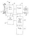
- FIG. 1is a schematic representation of an ultrasound imaging system in accordance with one embodiment of the invention
- FIG. 2is a cross-sectional view of a portion of a patient's anatomy including a site of interest for ultrasound imaging;
- FIG. 3is a flow chart of an imaging method in accordance with one embodiment of the invention.
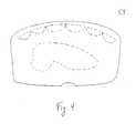
- FIG. 4is a schematic representation of an ultrasound image of the portion of the patient's anatomy of FIG. 2;
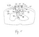
- FIG. 5shows a partially segmented version of the image of FIG. 4
- FIG. 6is a segmented ultrasound image of a portion of a subject's brain, showing refraction of transmitted ultrasound beams
- FIG. 7is a schematic representation of refraction caused by a prism shaped tissue region
- FIG. 8is a schematic representation of refraction of ultrasound beams caused by another a prism shaped tissue region with a vertex facing the ultrasound beams;
- FIG. 9is a schematic representation of an ultrasound probe comprising high and low frequency transducer elements.
- FIG. 10is a block diagram of elements of the ultrasound probe of FIG. 9 .
- FIG. 1is a schematic representation of an ultrasound imaging system 10 comprising an ultrasound probe 12 , a controller 14 , a Radio Frequency (“RF”) processor 16 , a beam former 18 , a signal and image processor 20 and a display 22 , in accordance with one embodiment of the invention.
- the ultrasound probecomprises a plurality of ultrasound transducer elements 12 a .
- the controller 14controls the operation of the system 10 , in accordance with software stored in a memory device 15 .
- the controller 14is coupled to the RF processor 16 , the beam former 18 and the signal and image processor 20 to provide signals for controlling the transmission, detection and processing of ultrasound beams.
- the beam former 18has an output coupled to an input of the ultrasound probe 12 , to provide driving signals with appropriate transmission delays to the transducer elements 12 a of the probe. Echo signals detected by the transducer elements are converted into electrical signals and provided to the beam former 18 , which applies appropriate reception delays to each signal. The signals are then summed by the beam former 18 .
- the RF processor 16has an input coupled to an output of the beam former 18 to receive the summed signals for further processing, as is known in the art.
- the signal and image processor 20has an input coupled to an output of the RF processor 16 to receive the processed signals for further processing and reconstruction, as is known in the art.
- the processor 20provides the reconstructed signals to the display 22 .
- the functions of the RF processor 16 and the signal and image processor 20may be performed by a single processor.
- One or more user interface devices 23may also be provided in the system 10 , with outputs coupled to an input of the controller 14 .
- the user interface device 23may comprise a trackball and/or a keyboard, for example.
- a user interface devicemay be coupled to the signal and image processor 20 , as well.
- the ultrasound probe 12typically comprises a transducer array 24 of ultrasound transducer elements 12 a .
- the transducer array 24may be a single row or a matrix of transducer elements 12 a .
- the transducer array 24may be curved, as shown in FIG. 1, for placement on a subject's skin.
- the transducer array 24may also be planar, parabolic, or any other suitable shape.
- the transducer elements 12 a of the transducer array 24may be piezoelectric transducer elements, such as piezoelectric ceramic pieces mounted in silicone rubber or any other material suitable for damping the mechanical coupling between the elements. Other materials may also be used for the array construction.
- the transducer array 24may be formed from one or more pieces of piezocomposite material, or any material that converts electrical energy to acoustic energy.
- the beam former 18is a control and processing device that may also comprise a frequency generator. Alternatively, a separate frequency generator may be coupled to the beam former 18 , as well. As discussed above, the beam former 18 imposes suitable transmission delays on each driving signal, so that the ultrasound beams transmitted by each transducer element 12 a constructively interfere at one or more focal points selected by an operator of the ultrasound imaging system 10 , proximate the site of interest.
- the controller 14typically computes the required transmission delays by calculating the propagation time from each transducer element 12 a to a focal point, assuming that the speed of sound is an average speed of sound in body tissue, or other uniform value, through all the tissue regions in the pass zone between each transducer element 24 and the focal point.
- the beam former 18also receives echo signals detected by the transducer elements 12 a from tissue and other reflecting bodies in the pass zone.
- the beam former 18applies suitable reception delays to the echo signals and sends the signals to the RF processor 16 and the signal and image processor 20 for reconstruction and display on the display 22 .
- the reception delays for the echo signalsare typically computed by the controller 14 based on the propagation time for an ultrasound signal reflected from a plurality of points at varying depths in the pass zone, and the average speed of sound in body tissue. For example, reception delays may be computed for 100 to 200 different depths in the pass zone. Transmission of ultrasound beams and reception of echo signals are alternated, under the control of the controller 14 , as is known in the art.
- the beam former 18may perform these computations instead of the controller 14 .
- the beam former 18may include the controller 14 , as well.
- the controller 14performs processing, logic and timing functions related to the operation of the ultrasound imaging system 10 .
- the controller functionsmay be provided by software, hardware, firmware, hardwiring, or combinations of any of these.
- the controller 14may be a general purpose, or special purpose, digital data processor or computer programmed with software in a conventional manner in order to calculate focusing delay times for use by the beam former 18 in accordance with the embodiments of the present invention, as discussed below.
- the memory 15may be a magnetic, optical or semiconductor memory device, including, without limitation, read only memory (“ROM”), including DVD ROM, or random access memory (“RAM”), including DVD RAM.
- the memory 15may be the hard drive of a computer.
- the softwaremay be provided on a machine readable medium, such as a CD-ROM or a floppy disk, for example.
- the softwaremay also be downloaded from a server via the Internet.
- FIG. 2is a cross-sectional view of a portion of a patient's anatomy including a site of interest 30 for ultrasound imaging.
- the site of interest 30is an organ, such as the liver.
- a transducer array 32comprising a plurality of transducer elements 33 is shown adjacent to the patient's skin 34 , aligned with the site of interest 30 .
- a coupling medium 36such as an ultrasound gel, is typically provided between the transducer array 32 and the skin 34 , to improve coupling of ultrasound energy between the subject's body and the transducer array 32 .
- the thickness of the coupling medium 36is shown exaggerated in FIG. 2 for illustrative purposes.
- Regions of different tissue types in a pass zone Z between the patient's skin and the site of interest 30are shown.
- a layer fat 38below the skin 34 , there is a layer fat 38 .
- muscle tissue regions 40Below the fat layer 38 are muscle tissue regions 40 .
- another layer of fat 42Between the muscle tissue regions 40 and the site of interest 30 is another layer of fat 42 .
- Three exemplary ultrasound beams B 1 , B 2 , B 3are shown being transmitted from three transducer elements 33 a , 33 b , 33 c in the transducer array 32 , focused on a focal point P within the site of interest 30 .
- all of the transducer elements 33are driven to transmit ultrasound beams focused on the focal point P. Additional focal points may be provided as well, but that may slow the imaging process.
- the beams B 1 , B 2 , B 3pass through the first fat region 38 , one of the muscle regions 40 , the second fat region 42 and part of the organ tissue of the site of interest 30 , as they travel to and from the focal point P.
- the transmission delays introduced to the ultrasound beams B 1 , B 2 , B 3 by the beam former 18are based on the uniform and average speed of sound in body tissue of 1540 m/s (or other such uniform speed considered to be an average speed of sound in body tissue), and the distance from each transducer element 33 a , 33 b , 33 c to each focal point P.
- the differing speeds of sound in each tissue type in the pass zone Zshift the expected phase of each beam at the focal point P.
- the desired constructive interference at the focal point Pis decreased and destructive interference is increased, degrading image contrast resolution.
- reception delays for reception of echo signalsare also conventionally computed using the same speed of sound as is used in computing the transmission delays.
- the phase alignment of the echo signalsis also therefore shifted, further degrading the image.
- geometrical errors in the location of objects in the imagemay be introduced.
- delay times for each ultrasound transducer element of an ultrasound probe for focusing ultrasound beams during transmission and/or receptionare determined based in part on a speed of sound other than the average speed of sound in body tissue.
- the speed of soundis the actual speed of sound through one or more of the tissue regions traversed by each ultrasound beam to and from the focal point P and reflecting bodies in the pass zone Z.
- the speedis used in conjunction with the distance each ultrasound beam traverses each region to compute the new delay times, which are used in subsequent ultrasound imaging scans to obtain corrected ultrasound images.
- the constructive interference of transmitted ultrasound beams at the focal point P and other focal points, if present,is thereby improved.
- the phase alignment of echo signalsis also improved.
- the contrast resolution of the corrected ultrasound imagesis thereby improved.
- FIG. 3is a flow chart of an ultrasound imaging method 50 in accordance with one embodiment of the present invention.
- step 52conventional ultrasound imaging is conducted of a site of interest, wherein delay times are computed for each of the transducer elements 33 of the transducer array 32 using an average and uniform speed of sound through tissue of 1540 m/s, or another such average and uniform value, for transmission and reception of ultrasound beams.
- One or more two dimensional sectional planes including the site of interestmay be imaged.
- a three dimensional volume including the site of interestmay be imaged.
- the results of the conventional imagingmay be reconstructed by the signal and image processor 20 and displayed on the display 22 of the ultrasound system 10 , or another computer system, in a conventional manner.
- A-mode or B-mode imagesmay be reconstructed, for example.
- FIG. 4is an example of a schematic representation of a resulting image.
- the boundaries of at least one tissue region in the pass zone Zare then determined on the image or images resulting from the initial ultrasound imaging scan, in step 54 .
- all the tissue regions on the pass zone Zare therefore segmented.
- the boundaries of the tissue regionsmay be determined in step 54 by segmentation. During segmentation, the boundaries are defined. Every voxel in the segmented volume is automatically mapped into a pass zone data set and correlated to a tissue type. Each voxel is assigned coordinates identifying its location in space ((X, Y) for a two dimensional data set and (X, Y, Z) for a three dimensional data set) and its tissue type (T), resulting in a data set comprising (X, Y, T) or (X, Y, Z, T) coordinates for each voxel.
- Tissue typemay be manually entered or automatically determined by an algorithm, as is known in the art.
- Segmentationmay be performed in a variety of manual, semi-automatic and automatic methods. For example, a human operator may manually segment one or a plurality of the images of the two dimensional sectional planes by tracing boundaries between one or more tissue types on each image 54 with a suitable interface device 23 (See FIG. 1 ), such as a pointer controlled by a mouse. A three dimensional volume of the pass zone Z may be interpolated from a sufficient number of segmented two dimensional images, if desired. The number of two dimensional images used to interpolate a three dimensional volume is dependent on the geometrical rate of change of the tissue region in the pass zone Z and the desired accuracy of the interpolation.
- an expanding area algorithmis implemented by the signal and image processor 20 to fill each region of the image or images designated by a user with the interface device 23 . For example, clicking on a mouse while a pointer is within a region of an image can cause execution of the expanding area algorithm to automatically fill the selected region.
- Other types of algorithmsmay be used, as well.
- a segmentation algorithm implemented by the signal and image processor 20may also be used to automatically segment each tissue region. Automatic or semi-automatic segmentation would be used to directly segment a three dimensional volume image.
- FIG. 5shows a segmented version of the image of FIG. 4, wherein the boundaries of the first fat region 38 , the boundaries of two of the muscle regions 40 , the second fat region 42 and the organ tissue of the site of interest 30 have been determined.
- Delay times for each transducer element 33 for use in transmission and reception focusingare then computed based, at least, in part on the speed of sound through the one or more segmented tissue regions and the boundaries of the those regions, in step 56 .
- the boundariesmay be used to determine the distance traveled by each beam through each tissue region.
- the distance traveled in each regionmay be determined by the controller 14 or the signal and image processor 20 under software control, using a ray calculation, for example.
- a reverse ray calculation or a forward ray calculation between each transducer element 24 and the reflector depthsmay be performed.
- FIG. 5shows how a reverse ray calculation may be performed on the segmented image of FIG. 4 from the focal point P to three of the transducer elements 33 a , 33 b , 33 c .
- the controller 14 or the signal and image processor 20compute rays R 1 , R 2 , R 3 from the focal point P to each of the transducer elements 33 a , 33 b , 33 c .
- the raysare drawn from each transducer element 33 to the focal point P.
- the rayscorrespond to the ultrasound beams B 1 , B 2 , B 3 in FIG. 3, respectively.
- a distance R 1 L 1 of the ray segment extending from the focal point P within the organ 30 to the boundary 30 a between the organ 30 and the adjacent tissue type, here the fat region 42is determined.
- the distance R 1 L 1may be computed by identifying the voxel coordinates on the boundary that the beam traverses. If the focal point P has voxel coordinates (Xp, Yp, Zp) and the boundary has voxel coordinates (Xq, Yq, Zq), then the distance R 1 L 1 between them is:
- the distances R 1 L 2 , R 1 L 3 and R 1 L 4 of the respective ray segments through the second fat region 42 , the muscle region 40 and the first fat region 38may be similarly computed based on the voxel coordinates of the boundaries 40 a , 38 a between the respective regions traversed by the beam B 1 .
- T R1L1R1L1 V ⁇ m / s , ( 2 )
- Vis the speed of sound through the organ tissue (1555 m/s for liver tissue, for example).
- the propagation timesmay be similarly computed for the ultrasound beam B 1 through the other tissue regions based on the ray segments R 1 L 2 , R 1 L 3 and R 1 L 4 , where V is the speed of sound in fat tissue (1460 m/s), muscle tissue (1600 m/s) and fat tissue, respectively.
- the propagation times for the ultrasound beam B 1 through each tissue regionis summed to yield an adjusted propagation time for the ultrasound beam B 1 .
- Propagation times for the other ultrasound beams B 2 , B 3 , and the ultrasound beams transmitted by each of the other transducer elements 33 of the transducer array 32 to the focal point P,are computed in a similar manner.
- the adjusted propagation times for each transducer element 33is then used by the controller 14 to determine adjusted transmission delays for each ultrasound beam transmitted by each transducer element 33 , in step 56 .
- Reception delays for processing the echo signals from the pass zone Zare also similarly computed, based on selected depths in the pass zone.
- FIG. 5also shows a ray R 4 extending from one of a plurality of points D in the pass zone Z to the transducer element 33 c .
- the propagation time for the ultrasound beams traveling from the point D to the transducer 33 cis determined.
- a ray R 4is drawn and its length in the fat tissue region 42 is determined based on the voxel coordinates at the point D and the voxel coordinates of the boundary between the fat tissue region 42 and the muscle tissue region 40 , by equation (1), above.
- the propagation time TR 4 L 2 in the fat tissue region 42is then determined by equation (2), above.
- the propagation times for the ultrasound beam traveling along the ray R 4 , through the tissue regions 40 and 38are similarly computed.
- the propagation timesare summed and used to compute an adjusted reception delay for an echo signal reflected from the point D to the transducer element 33 c .
- Raysare similarly drawn from the point D to each of the other transducer elements 33 and adjusted delay times are similarly computed.
- Adjusted reception delaysmay b e computed at 100 to 200 points along the ray from the focal point P to each ultrasound element 33 .
- a speed that is “about” the speed in the respective tissue regionis preferably used.
- the term “about the speed of sound” for fat tissueis a speed in a range of plus or minus 3% of the speed of sound of 1460 m/s.
- a speed in a range of plus or minus, 1% of 1460 m/sis preferred.
- the speed of 1460 m/sis most preferred.
- “about the speed of sound”is a speed in a range of plus or minus 2% of 1600 m/s.
- a speed in a range of plus or minus 1% of 1600 m/sis preferred and the speed of 1600 m/s is more preferred.
- “about the speed of sound”are speeds in ranges of 2.0% of the speeds of 1555 m/s and 1565 m/s, respectively. Speeds in ranges of plus or minus 1.0% of the respective speeds are more preferred. Speeds in ranges of plus or minus 0.5% of the respective speeds are even more preferred and the speeds of 1555 m/s and 1565 m/s for liver and kidney tissue are most preferred.
- “about the speed of sound”is a speed in a range of plus or minus 40% of the speed of 3000 m/s.
- a speed in a range of plus or minus 20% of 3000 m/sis preferred, a speed in a range of plus or minus 10% of 3000 m/s is more preferred and the speed of 3000 m/s is most preferred.
- the speed of sound in brain tissuehas been observed to be about 1570 m/s.
- a speed of “about the speed of sound” for brain tissueis in a range of plus or minus 2.0% of 1570 m/s.
- a speed in a range of plus or minus 1.0% of 1570 m/smay be used. 1570 m/s may be used, as well.
- a new, corrected ultrasound imaging scanis conducted in step 58 employing the adjusted delay times.
- the corrected imageis evaluated in step 59 by the signal and image processor 20 , the controller 14 or visually. If the image has sufficient contrast resolution, the process is completed (step 60 ).
- the tissue aberration correctionmay not have been sufficient. This may be due to inaccuracies in the initial ultrasound image used for segmentation in step 54 , due to tissue inhomogeneities. While generally the segmented boundaries of the initial image will be accurate enough to compute sufficiently improved propagation times, that might not always be the case. Step 54 may then be conducted again based on the corrected image. The segmented boundaries on the corrected image should be more accurate then the segmented boundaries on the initial image.
- Adjusted delay timesare computed again in step 56 and employed in conducting another corrected ultrasound imaging scan in step 58 .
- the twice corrected imageis evaluated again in step 59 . If sufficient, the process may be ended. If still not sufficient, step 54 may be conducted again on the twice corrected image. This process may be repeated until an adequate image is generated.
- Contrast resolution problemsmay also be due to deviations from the actual speed of sound in particular tissue regions in certain individuals. Improving the accuracy of the segmented boundaries by repeating steps 54 , 56 and 58 with corrected images will generally provide sufficient improvements in contrast resolution despite such deviations.
- each tissue region in the pass zonewas segmented and the actual speed of sound in that tissue type was used in conjunction with the distance traveled by each ultrasound beam in that tissue type, to compute the adjusted delay times. While providing a high level of improvement in contrast resolution, that is not always necessary.
- the difference between the speed of sound though fat tissue (1440 m/s) and the average speed of sound in body tissue (1540 m/s)is about 6.5%, which may cause considerable phase shifts that can seriously degrade contrast resolution.
- the speed of sound in muscle tissue (1600 m/s)is about 4.0% faster than the average speed of sound in body tissue, which may cause some phase shifts that can also decrease contrast resolution.
- the speed of sound in the liveris 1555 m/s, which is about 1.0% faster than the average speed of sound of 1540 m/s.
- the speed of sound in a kidneyis 1565 m/s, which is about 2.0% faster than the average speed of sound in body tissue of 1540 m/s. Such small deviations from the average speed of sound would only cause small or negligible phase shifts that may be ignored except where the highest contrast resolution is desired.
- certain of the speed ranges for different tissue types recited aboveoverlap portions of the range of the average speed of sound in body tissue of 1540 m/s plus or minus 3%. Where an average speed of sound in body tissue is used that is within about 4% of the speed of sound in a particular tissue type, the average speed of sound in body tissue may be used to determine the propagation time through that tissue region, at least initially.
- the tissue aberration correction process in ultrasound imaging of a pass zone containing only soft tissuemay be simplified by only segmenting the fat tissue region or regions in the pass zone and only determining the distances traveled by each ultrasound beam in the segmented regions. The distance traveled in the segmented region may then be subtracted from the total distance traveled by the respective ultrasound beam between the transducer element 33 and the focal point P, which is usually known within acceptable tolerances, to determine the distance traveled in the remaining soft tissue regions. The average speed of sound in body tissue may be used to determine the propagation time in the remaining soft tissue. If that does not yield an adequate image, additional improvement in the correction and hence further improvements in contrast resolution may be obtained by repeating step 56 using the speed of sound in muscle tissue to determine the propagation time in the remaining soft tissue regions.
- Step 56may be repeated with the same initial image, or with a currently corrected ultrasound image derived from the partial correction, as discussed above.
- the software controlling the tissue aberration correction methodmay be designed to conduct only one type of analysis or allow for an operator to choose among the options.
- the speed of sound through bone tissue(3000 m/s for skull bone tissue, for example), is much faster than the average speed of sound in body tissue, resulting in significant phase shifts and resulting loss in contrast resolution. It would therefore be advantageous to segment bone tissue regions and use the actual speed of sound in bone tissue to determine the propagation time of the ultrasound beams traversing bone tissue.
- the other soft tissue regions in the pass zonemay be dealt with by segmenting each tissue region in the pass zone or following one of the simplified methods discussed above. (We note that the speed of sound in skull bone is sometimes quoted as 4080 m/s. While that or some other value may be used, we have found the value of 3,000 m/s to be more accurate).
- Tissue inhomogeneitycan also cause refraction that can alter the path, and hence the distance traveled by the ultrasound beam in each tissue region.
- the phase of the transmitted ultrasound beams at the focal point and the phase of the echo signals received by the transducer elementsmay thereby be further shifted, further degrading the contrast resolution of the resulting ultrasound images.
- the effects of refraction of the beams as the beams enter each tissue regionmay also be considered in determining the adjusted focusing delay times for further improvements in contrast resolution in step 56 .
- ⁇ 1 , ⁇ 2are the angles between the normal to the surface and the incident and refracted rays in the respective tissue regions and C 1 , C 2 are the speeds of sound in the respective tissue regions.
- FIG. 6is a segmented ultrasound image of a pass zone Z 1 between the transducer array 32 and a site of interest within a patient's brain.
- a layer of coupling material 78is shown between the transducer array 32 and the skin 70 , as discussed above.
- the speed of sound in brain tissueis about 1540 m/s.
- the transducer array 32is shown adjacent to the skin 70 and the skull bone tissue 72 for imaging brain tissue 76 .
- the skull bone tissue 72typically comprises two layers of cortical bone with a layer of trabecular bone in between. Trabecular bone and cortical bone have different densities, which will vary the speed of sound.
- the skull bone tissuemay be considered to be homogenous and an average speed of sound in skull bone tissue of 3000 m/s may be used for the entire bone tissue region 72 .
- the multiple layers of bone tissuemay be segmented and the speeds of sound and the distance traveled in each segmented region may be separately considered in accordance with the teachings of the present invention, if desired or found to be necessary for further improvements in the contrast resolution.
- First and second ultrasound beams B 4 , B 5are shown being transmitted by transducer elements 33 a , 33 c at opposite ends of the transducer array 32 , focused on a focal point P 10 , assuming that there is no refraction.
- Ray R 14shows the effect of refraction on the beam B 4 due to the interface between the bone tissue region 72 and the skin 70 .
- the ray R 16shows the effect of refraction on the ray R 14 at the interface between the bone tissue region 72 and the brain tissue region 76 . Because of refraction, the beam B 4 does not intercept the focal point P 10 .
- ray segments R 18 , R 20need to be generated by the controller 14 between the first transducer element 33 a and the focal point P 10 , as either forward rays drawn from the transducer element 33 a to the focal point P 10 or reverse rays drawn from the focal point P 10 to the transducer element 33 a on a segmented image.
- the lengths of the ray segments R 18 , R 20may be determined based on the coordinates of the boundaries of the segmented tissue regions intercepted by the rays through Equation 1, above.
- the propagation times for ultrasound beams traveling the lengths of the ray segments R 18 , R 20are determined through Equation 2, above.
- the speed of sound in bone tissue of 3000 m/sis used with the ray segment R 18 .
- the speed of sound in brain tissue of 1540 m/sis preferably used with the ray segment R 20 . While the speed of sound in brain tissue is the same as the average speed of sound in body tissue, a new propagation time for the ray segment R 20 needs to be computed because the refraction of the ray changes the distance traveled. The propagation times are summed to obtain a total propagation time for use in computing a transmission delay in step 56 .
- Ray segmentsmay be similarly generated and transmission delays similarly computed for ultrasound beams transmitted by all the other transducer elements 33 . (It is noted that ultrasound beams transmitted by a transducer element that is normal to a boundary of a tissue region will not be refracted by the boundary.). Reception delays are similarly computed to take refraction into account, as well.
- a new ultrasound imaging scanis conducted in step 58 employing the adjusted delay times to obtain a corrected image. Because of inaccuracies in the segmented boundaries in the initial ultrasound image due to the degraded contrast resolution, the initial refraction corrected ultrasound beams may miss the actual focal point P 10 by more than an acceptable tolerance. If the refraction corrected ray is outside a predetermined tolerance, which may be determined by the controller 14 or the signal and image processor 20 , or the corrected image itself does not appear to have sufficient contrast resolution, the corrected ultrasound image may be segmented in step 54 and the adjusted delay times calculated again in step 56 .
- the corrected ultrasound imagewill provide some correction for tissue inhomogeneities that will enable improved segmentation.
- the twice refraction and inhomogeneity corrected ultrasound beamsshould therefore provide better aberration correction than the first set of refraction and inhomogeneity corrected ultrasound beams.
- the decision to iterate the phase aberration correctione.g. segmenting the corrected image 54 and re-computating the adjusted delays 56 , could be based on the change in the phase aberration values between two consecutive iteration steps. As an example, iteration of steps 54 - 59 may be stopped when the change is less than ⁇ 5% of the previous step correction. Another possible criteria for stopping iterations could be frequency content in a predefined bandwidth in the resulting image.
- Refraction correctionis preferably performed if bone tissue is present in the pass zone. Where only soft tissue is present in the pass zone, the refraction correction is optional.
- the controller 14may be programmed to enable selection of refraction correction by an operator, depending on whether bone tissue is present.
- step 54may be repeated with the corrected ultrasound image and refraction correction may be included in step 56 .
- FIG. 7shows the transducer array 32 of FIG. 5 and a segmented fat tissue region 80 in a pass zone Z 2 .
- the tissue 81 between the transducer array 32 and the fat tissue region 80is assumed to be muscle tissue. Other tissue regions in the pass zone Z 2 are not shown to simplify the view.
- the segmented tissue region 80has a uniformly changing thickness across a plane containing the transducer array 32 .
- Such a tissue regionmay be modeled as a prism.
- Two exemplary ultrasound beams B 6 , B 7are shown being transmitted from the two transducer elements 33 a , 33 c on opposite sides of the transducer array 32 .
- the beams B 6 , B 7are intended to be focused on a focal point P 12 selected by an operator of the ultrasound imaging system 10 .
- refractioncauses the two ultrasound beams B 4 , B 5 , and all the other ultrasound beams transmitted by the transducer elements 33 , to be focused on a new focal point P 14 at a different position than the selected focal point P 12 .
- the refracted beams B 6 , B 7are indicated, partially in solid lines and partially in dotted lines.
- the actual paths of the beam B 6 , B 7 through the prismare indicated by solid lines B 6 ′, B 6 ′′, B 7 ′, B 7 ′′. While shifting the position of the focal point P 12 in space, because of the shape of the tissue region 80 , the desired degree of constructive interference at the focal point is within acceptable tolerances.
- Shifting the position of the focal pointmay introduce geometric errors in the positions of objects in the ultrasound image. Such errors can be detrimental in medical procedures, such as needle biopsy procedures planned with ultrasound images. It is noted that if the ultrasound imaging is being conducted while the needle is in the pass zone Z 1 , the position of the needle and the site of interest will typically be shifted proportionally and location of the site of interest will not be compromised. If a surgeon is relying on images where the needle is not in the pass zone, however, such geometric errors could prevent the precise biopsy guidance.
- the controller 14corrects the displacement of the focal point P 12 due to refraction by the tissue region 80 in step 56 by generating forward or reverse ray segments between the desired focal point P 12 and each transducer element.
- the raysare drawn taking into consideration Snell's law (Equation 3), the segmented boundaries and the speeds of sound in the tissue region 80 and adjacent tissue regions, as described above with respect to FIG. 6 . Since the rate of change of the depth of the tissue region 80 is monotonic and linear, traversal of the tissue region 80 by the ultrasound beams affects all the beams proportionally. The phases of the beams are shifted in such a way that the ultrasound beams are steered. Constructive interference at the shifted focal point P 14 is not, therefore, appreciably degraded.
- the propagation times of each refracted beamis determined by the ray calculation, as discussed above. For example, an ultrasound beam emitted by the transducer element 33 a along a ray segment R 22 element will be refracted by the tissue region 80 to form beams along rays R 24 and R 26 . The beam corresponding to the ray R 26 will intercept the focal point R 12 . The propagation times of ultrasound beams corresponding to the rays R 22 , R 24 , R 26 are used to determine the transmission delay for the transducer element 33 a . Rays are similarly computed for the other transducer elements of the array 32 to provide beams focused on the focal point P 12 .
- the software implementing the correction processmay allow for separation corrections for defocusing (decrease in constructive interference) and focal point shift.
- small geometric shifts in objects in the imagemay not interfere with the evaluation of the image. It may not, therefore, be necessary to correct for focal point shift.
- the ultrasound imageis to be used to guide a needle biopsy procedure, in contrast, even small geometrical shifts in objects in the image may be critical and need to be corrected, as discussed above.
- FIG. 8is an example of another segmented tissue region 90 that may be modeled as a prism, where two faces 92 a , 92 b and a vertex 94 of the prism intercept the ultrasound beams transmitted by the transducer array 32 .
- the tissue region 90is positioned such that the ultrasound beams transmitted by the transducer array 32 are substantially bisected.
- three exemplary ultrasound beams B 8 , B 9 , B 10are shown being transmitted by the three respective transducer elements 33 a , 33 e , 33 c .
- the ultrasound beams B 8 , B 9 , B 10are intended to be focused onto a focal point P 16 .
- the ultrasound beams B 9 and B 10 , and other ultrasound beams transmitted by the transducer elements 33 that impinge on the face 92 bare focused onto a focal point P 18 .
- the ultrasound beam B 8 , and other ultrasound beams transmitted by the transducer elements 33 that impinge on the face 92 awill be focused on a focal P 20 .
- the ultrasound beams focused on the focal point P 20are not shown to simplify the illustration.
- the focal points, P 18 and P 20are symmetrically positioned with respect to the original focal point P 16 . Each shifted focal point P 18 , P 20 receives about half of the ultrasound energy that would be received at the original focal point P 16 .
- Segmentation of the ultrasound image or images and computation of the transmission delay timesmay be conducted in nearly real-time.
- the usercan switch on a tissue aberration correction mode to implement the method 50 , or other such method in accordance with the invention.
- the system 10will automatically conduct the initial scan of step 52 , automatically segment the image in step 54 and compute adjusted delay times in step 56 , in one or a few seconds, and then conduct a corrected imaging scan employing the adjusted delay times in step 58 .
- the processmay be conducted so quickly that the ultrasound probe 12 will be in the same position, within tolerances, with respect to the patient and focal point P during the initial and corrected imaging scars. If the operator feels that the position of the ultrasound probe 12 has moved beyond the acceptable tolerances, the operator can initiate a new initial scan and subsequent steps of the process.
- a motion trackersuch as an electromagnetic motion tracker, may also be used to correlate the position of the ultrasound probe 12 during the initial ultrasound imaging scan of step 52 to a subsequent position of the ultrasound probe during the corrected ultrasound imaging scan in step 58 , if necessary. The adjusted propagation times may thereby be further adjusted based on the new position of the ultrasound probe 12 .
- a “Flock of Birds®” electromagnetic trackeravailable from Ascension Technology Corporation, Burlington, Vermont, may be used, for example.
- the usermay decide whether to implement the tissue correction mode based on the quality of an image or images from the initial ultrasound imaging scan.
- the motion tracker discussed above, or other such motion trackermay be used to correlate the position of the ultrasound probe 12 during the initial ultrasound imaging scan and the corrected ultrasound imaging scan.
- the delay times computed in step 56may be based on phase shifts caused by traversal through tissue regions where the actual speed of sound in that region is not the same as the average speed of sound.
- the phase shiftmay be used by the controller 14 to determine adjustments to the original time delays for each transducer element so that the ultrasound beams constructively interfere at the focal points P.
- phase shift ⁇in degrees, introduced to an ultrasound beam due to traversal through a tissue region where the speed of sound is different than the average speed of sound in tissue is:
- the original delay timesmay be adjusted by the controller 14 to compensate.
- the imaging parameters for the initial images derived in step 52may be different from the imaging parameters used in step 58 , to optimize for segmentation or imaging, respectively.
- low frequency sound wavespenetrate tissue more deeply than higher frequency sound waves and are less susceptible to tissue aberrations. Images resulting from the use of low frequencies, however, have less contrast resolution than images resulting from the use of higher frequencies. Low frequencies may therefore provide better images for segmentation and may therefore be used in conducting the initial, conventional imaging scan of step 52 . Higher frequencies may then be used in the corrected ultrasound imaging of step 58 to obtain higher images with better contrast resolution.
- the ultrasound transducer elements 33 of the transducer array 32may be wide bandwidth transducer elements having a range of 1.5-4.0 Megahertz (“MHz”).
- the initial ultrasound scan in step 52may be conducted at a frequency of 1.5 MHz and the corrected ultrasound imaging scan of step 58 may be conducted at a frequency of 4.0 MHz.
- the frequency rangemay vary dependent upon the clinical application.
- the ultrasound probe 12may comprise multiple sections of transducer elements, each for transmitting ultrasound beams at a high or low frequency.
- FIG. 9is a schematic representation of a side view of an ultrasound probe 100 in accordance with another embodiment comprising a handle 102 , a cable 104 and a body portion 106 supporting a transducer array 108 .
- the transducer array 108is a linear curved array comprising a central section 110 of low frequency transducer elements 112 and outer sections 114 , 116 comprising high frequency transducer elements 118 .
- the transducer elements 112 of the central section 110may be driven by the beam former 18 at a low frequency, such as 1.0 MHz, for example, during the initial ultrasound imaging scan of step 52 .
- the transducer elements 118 of the high frequency sections 114 , 116may then be driven by the beam former 18 at a high frequency, such as 4.0 MHz, during ultrasound imaging with the adjusted delay times in step 58 . It is preferred to locate the outer, high frequency sections 114 , 116 at respective sides of the low frequency central section 110 so that the high frequency ultrasound beams transmitted during the corrected ultrasound imaging scan of step 58 have a maximum aperture.
- the high frequency transducers 118are preferably provided around the periphery of the matrix, while the low frequency transducers 112 are preferably provided in a central portion of the matrix.
- Separate low and high frequency ultrasound probes 12may also be used for the initial and subsequent imaging scans, in conjunction with tracking, as discussed above.
- FIG. 10is a block schematic diagram of the electronic components of the ultrasound probe 100 of FIG. 9 .
- An acoustic module 130includes the high and low frequency transducer elements 112 , 118 (not shown in this view). Electrical connectors, such as wires, connect each transducer element 112 , 118 to connectors of a printed circuit 132 , which electrically couples the acoustic module 130 to the cable 104 .
- a matching circuit 134is optionally provided to match the impedance between the transducer elements 112 , 118 and the front end electronics.
- the cable 104is connected to a multi-pin connector 136 for electrical coupling to the beam former 18 .
- Imaging parametersinclude the pulse shape of an individual ultrasound pulse and the burst length of ultrasound pulses or cycles.
- a wider pulsewhich has a higher energy content and lower frequency content, may provide better images for segmentation in the initial ultrasound imaging scan of step 52 .
- a shorter pulsewhich has a higher frequency content, may provide better contrast resolution in the corrected ultrasound imaging of step 58 .
- a longer burst lengthmay also provide a better image for segmentation while a shorter burst length, in conjunction with a higher frequency, may provide better contrast resolution in step 58 .
- Pulse shape and burst lengthmay also be varied by the beam former 18 , under the control of controller 14 .
Landscapes
- Engineering & Computer Science (AREA)
- Health & Medical Sciences (AREA)
- Physics & Mathematics (AREA)
- Life Sciences & Earth Sciences (AREA)
- Remote Sensing (AREA)
- Radar, Positioning & Navigation (AREA)
- Molecular Biology (AREA)
- General Health & Medical Sciences (AREA)
- Radiology & Medical Imaging (AREA)
- Biomedical Technology (AREA)
- Heart & Thoracic Surgery (AREA)
- Medical Informatics (AREA)
- Nuclear Medicine, Radiotherapy & Molecular Imaging (AREA)
- Surgery (AREA)
- Animal Behavior & Ethology (AREA)
- Pathology (AREA)
- Public Health (AREA)
- Veterinary Medicine (AREA)
- Computer Networks & Wireless Communication (AREA)
- General Physics & Mathematics (AREA)
- Biophysics (AREA)
- Acoustics & Sound (AREA)
- Computer Vision & Pattern Recognition (AREA)
- Neurology (AREA)
- Ultra Sonic Daignosis Equipment (AREA)
Abstract
Description


Claims (57)
Priority Applications (1)
| Application Number | Priority Date | Filing Date | Title |
|---|---|---|---|
| US10/190,787US6705994B2 (en) | 2002-07-08 | 2002-07-08 | Tissue inhomogeneity correction in ultrasound imaging |
Applications Claiming Priority (1)
| Application Number | Priority Date | Filing Date | Title |
|---|---|---|---|
| US10/190,787US6705994B2 (en) | 2002-07-08 | 2002-07-08 | Tissue inhomogeneity correction in ultrasound imaging |
Publications (2)
| Publication Number | Publication Date |
|---|---|
| US20040006272A1 US20040006272A1 (en) | 2004-01-08 |
| US6705994B2true US6705994B2 (en) | 2004-03-16 |
Family
ID=29999910
Family Applications (1)
| Application Number | Title | Priority Date | Filing Date |
|---|---|---|---|
| US10/190,787Expired - LifetimeUS6705994B2 (en) | 2002-07-08 | 2002-07-08 | Tissue inhomogeneity correction in ultrasound imaging |
Country Status (1)
| Country | Link |
|---|---|
| US (1) | US6705994B2 (en) |
Cited By (86)
| Publication number | Priority date | Publication date | Assignee | Title |
|---|---|---|---|---|
| US20040122323A1 (en)* | 2002-12-23 | 2004-06-24 | Insightec-Txsonics Ltd | Tissue aberration corrections in ultrasound therapy |
| US20060058678A1 (en)* | 2004-08-26 | 2006-03-16 | Insightec - Image Guided Treatment Ltd. | Focused ultrasound system for surrounding a body tissue mass |
| US20060189972A1 (en)* | 2005-02-02 | 2006-08-24 | Gynesonics, Inc. | Method and device for uterine fibroid treatment |
| US20070016039A1 (en)* | 2005-06-21 | 2007-01-18 | Insightec-Image Guided Treatment Ltd. | Controlled, non-linear focused ultrasound treatment |
| US20070036404A1 (en)* | 2005-08-15 | 2007-02-15 | Wenguang Li | Medical image analysis |
| US20070161905A1 (en)* | 2006-01-12 | 2007-07-12 | Gynesonics, Inc. | Intrauterine ultrasound and method for use |
| US20070167781A1 (en)* | 2005-11-23 | 2007-07-19 | Insightec Ltd. | Hierarchical Switching in Ultra-High Density Ultrasound Array |
| US20070179380A1 (en)* | 2006-01-12 | 2007-08-02 | Gynesonics, Inc. | Interventional deployment and imaging system |
| US20070197918A1 (en)* | 2003-06-02 | 2007-08-23 | Insightec - Image Guided Treatment Ltd. | Endo-cavity focused ultrasound transducer |
| US20070249936A1 (en)* | 2006-04-20 | 2007-10-25 | Gynesonics, Inc. | Devices and methods for treatment of tissue |
| US20070249939A1 (en)* | 2006-04-20 | 2007-10-25 | Gynesonics, Inc. | Rigid delivery systems having inclined ultrasound and curved needle |
| US20080082026A1 (en)* | 2006-04-26 | 2008-04-03 | Rita Schmidt | Focused ultrasound system with far field tail suppression |
| US20080281182A1 (en)* | 2007-05-07 | 2008-11-13 | General Electric Company | Method and apparatus for improving and/or validating 3D segmentations |
| US20080319356A1 (en)* | 2005-09-22 | 2008-12-25 | Cain Charles A | Pulsed cavitational ultrasound therapy |
| US20090088623A1 (en)* | 2007-10-01 | 2009-04-02 | Insightec, Ltd. | Motion compensated image-guided focused ultrasound therapy system |
| US20090099544A1 (en)* | 2007-10-12 | 2009-04-16 | Gynesonics, Inc. | Methods and systems for controlled deployment of needles in tissue |
| US20090171254A1 (en)* | 2008-01-02 | 2009-07-02 | Leonid Kushculey | Time-reversal ultrasound focusing |
| US20090287081A1 (en)* | 2008-04-29 | 2009-11-19 | Gynesonics , Inc | Submucosal fibroid ablation for the treatment of menorrhagia |
| US20100030076A1 (en)* | 2006-08-01 | 2010-02-04 | Kobi Vortman | Systems and Methods for Simultaneously Treating Multiple Target Sites |
| US20100056962A1 (en)* | 2003-05-22 | 2010-03-04 | Kobi Vortman | Acoustic Beam Forming in Phased Arrays Including Large Numbers of Transducer Elements |
| US20100056926A1 (en)* | 2008-08-26 | 2010-03-04 | Gynesonics, Inc. | Ablation device with articulated imaging transducer |
| US20100069797A1 (en)* | 2005-09-22 | 2010-03-18 | Cain Charles A | Pulsed cavitational ultrasound therapy |
| US20100125193A1 (en)* | 2008-11-19 | 2010-05-20 | Eyal Zadicario | Closed-Loop Clot Lysis |
| US20100179425A1 (en)* | 2009-01-13 | 2010-07-15 | Eyal Zadicario | Systems and methods for controlling ultrasound energy transmitted through non-uniform tissue and cooling of same |
| US20100268088A1 (en)* | 2009-04-17 | 2010-10-21 | Oleg Prus | Multimode ultrasound focusing for medical applications |
| US20100318002A1 (en)* | 2009-06-10 | 2010-12-16 | Oleg Prus | Acoustic-Feedback Power Control During Focused Ultrasound Delivery |
| US20110034800A1 (en)* | 2009-08-04 | 2011-02-10 | Shuki Vitek | Estimation of alignment parameters in magnetic-resonance-guided ultrasound focusing |
| US20110040190A1 (en)* | 2009-08-17 | 2011-02-17 | Jahnke Russell C | Disposable Acoustic Coupling Medium Container |
| US20110046472A1 (en)* | 2009-08-19 | 2011-02-24 | Rita Schmidt | Techniques for temperature measurement and corrections in long-term magnetic resonance thermometry |
| US20110046475A1 (en)* | 2009-08-24 | 2011-02-24 | Benny Assif | Techniques for correcting temperature measurement in magnetic resonance thermometry |
| US20110054363A1 (en)* | 2009-08-26 | 2011-03-03 | Cain Charles A | Devices and methods for using controlled bubble cloud cavitation in fractionating urinary stones |
| US20110066032A1 (en)* | 2009-08-26 | 2011-03-17 | Shuki Vitek | Asymmetric ultrasound phased-array transducer |
| US20110109309A1 (en)* | 2009-11-10 | 2011-05-12 | Insightec Ltd. | Techniques for correcting measurement artifacts in magnetic resonance thermometry |
| US8206300B2 (en) | 2008-08-26 | 2012-06-26 | Gynesonics, Inc. | Ablation device with articulated imaging transducer |
| US8262574B2 (en) | 2009-02-27 | 2012-09-11 | Gynesonics, Inc. | Needle and tine deployment mechanism |
| US20120281902A1 (en)* | 2010-02-23 | 2012-11-08 | Canon Kabushiki Kaisha | Ultrasonic imaging apparatus and method of controlling delay |
| USRE43901E1 (en) | 2000-11-28 | 2013-01-01 | Insightec Ltd. | Apparatus for controlling thermal dosing in a thermal treatment system |
| US20130178740A1 (en)* | 2012-01-05 | 2013-07-11 | Samsung Medison Co., Ltd. | Method and apparatus for providing ultrasound image |
| US8539813B2 (en) | 2009-09-22 | 2013-09-24 | The Regents Of The University Of Michigan | Gel phantoms for testing cavitational ultrasound (histotripsy) transducers |
| US8661873B2 (en) | 2009-10-14 | 2014-03-04 | Insightec Ltd. | Mapping ultrasound transducers |
| US8852103B2 (en) | 2011-10-17 | 2014-10-07 | Butterfly Network, Inc. | Transmissive imaging and related apparatus and methods |
| US8932237B2 (en) | 2010-04-28 | 2015-01-13 | Insightec, Ltd. | Efficient ultrasound focusing |
| US8968210B2 (en) | 2008-10-01 | 2015-03-03 | Covidien LLP | Device for needle biopsy with integrated needle protection |
| US8979871B2 (en) | 2009-08-13 | 2015-03-17 | Monteris Medical Corporation | Image-guided therapy of a tissue |
| US9049783B2 (en) | 2012-04-13 | 2015-06-02 | Histosonics, Inc. | Systems and methods for obtaining large creepage isolation on printed circuit boards |
| US9144694B2 (en) | 2011-08-10 | 2015-09-29 | The Regents Of The University Of Michigan | Lesion generation through bone using histotripsy therapy without aberration correction |
| US9186128B2 (en) | 2008-10-01 | 2015-11-17 | Covidien Lp | Needle biopsy device |
| US9332973B2 (en) | 2008-10-01 | 2016-05-10 | Covidien Lp | Needle biopsy device with exchangeable needle and integrated needle protection |
| US9333038B2 (en) | 2000-06-15 | 2016-05-10 | Monteris Medical Corporation | Hyperthermia treatment and probe therefore |
| US9433383B2 (en) | 2014-03-18 | 2016-09-06 | Monteris Medical Corporation | Image-guided therapy of a tissue |
| US9504484B2 (en) | 2014-03-18 | 2016-11-29 | Monteris Medical Corporation | Image-guided therapy of a tissue |
| US9636133B2 (en) | 2012-04-30 | 2017-05-02 | The Regents Of The University Of Michigan | Method of manufacturing an ultrasound system |
| US9642593B2 (en) | 2014-09-19 | 2017-05-09 | MuscleSound, LLC | System and method for non-invasive determination of human body fat |
| US9667889B2 (en) | 2013-04-03 | 2017-05-30 | Butterfly Network, Inc. | Portable electronic devices with integrated imaging capabilities |
| US9782565B2 (en) | 2008-10-01 | 2017-10-10 | Covidien Lp | Endoscopic ultrasound-guided biliary access system |
| US9852727B2 (en) | 2010-04-28 | 2017-12-26 | Insightec, Ltd. | Multi-segment ultrasound transducers |
| US9943708B2 (en) | 2009-08-26 | 2018-04-17 | Histosonics, Inc. | Automated control of micromanipulator arm for histotripsy prostate therapy while imaging via ultrasound transducers in real time |
| US9981148B2 (en) | 2010-10-22 | 2018-05-29 | Insightec, Ltd. | Adaptive active cooling during focused ultrasound treatment |
| US10058342B2 (en) | 2006-01-12 | 2018-08-28 | Gynesonics, Inc. | Devices and methods for treatment of tissue |
| US10219815B2 (en) | 2005-09-22 | 2019-03-05 | The Regents Of The University Of Michigan | Histotripsy for thrombolysis |
| EP3328285A4 (en)* | 2015-07-31 | 2019-04-03 | Endra, Inc. | METHOD AND SYSTEM FOR FAT-INDUCED ABERRATION CORRECTIONS |
| US10293187B2 (en) | 2013-07-03 | 2019-05-21 | Histosonics, Inc. | Histotripsy excitation sequences optimized for bubble cloud formation using shock scattering |
| US10327830B2 (en) | 2015-04-01 | 2019-06-25 | Monteris Medical Corporation | Cryotherapy, thermal therapy, temperature modulation therapy, and probe apparatus therefor |
| US10330782B2 (en) | 2014-11-07 | 2019-06-25 | Tessonics Corporation | Ultrasonic adaptive beamforming method and its application for transcranial imaging |
| US10463346B2 (en) | 2010-06-25 | 2019-11-05 | Musclesound, Inc. | System and method for target muscle glycogen score determination and evaluation |
| US10595819B2 (en) | 2006-04-20 | 2020-03-24 | Gynesonics, Inc. | Ablation device with articulated imaging transducer |
| US10675113B2 (en) | 2014-03-18 | 2020-06-09 | Monteris Medical Corporation | Automated therapy of a three-dimensional tissue region |
| WO2020172272A1 (en)* | 2019-02-19 | 2020-08-27 | Endra Life Sciences Inc. | Method and system for reconstructing a thermoacoustic image |
| US10780298B2 (en) | 2013-08-22 | 2020-09-22 | The Regents Of The University Of Michigan | Histotripsy using very short monopolar ultrasound pulses |
| US10993770B2 (en) | 2016-11-11 | 2021-05-04 | Gynesonics, Inc. | Controlled treatment of tissue and dynamic interaction with, and comparison of, tissue and/or treatment data |
| US11013490B2 (en) | 2016-11-15 | 2021-05-25 | Musclesound, Inc. | Non-invasive determination of muscle tissue size |
| US11058399B2 (en) | 2012-10-05 | 2021-07-13 | The Regents Of The University Of Michigan | Bubble-induced color doppler feedback during histotripsy |
| US11064971B2 (en) | 2016-11-30 | 2021-07-20 | Musclesound, Inc. | Non-Invasive determination of muscle tissue quality and intramuscular fat |
| US11096658B2 (en) | 2017-02-02 | 2021-08-24 | Musclesound, Inc. | Non-invasive determination of pennation angle and/or fascicle length |
| US11135454B2 (en) | 2015-06-24 | 2021-10-05 | The Regents Of The University Of Michigan | Histotripsy therapy systems and methods for the treatment of brain tissue |
| US11160493B2 (en) | 2017-03-03 | 2021-11-02 | Musclesound, Inc. | System and method for determining a subject's muscle fuel level, muscle fuel rating, and muscle energy status |
| US20220031287A1 (en)* | 2010-06-09 | 2022-02-03 | Regents Of The University Of Minnesota | Dual mode ultrasound transducer (dmut) system and method for controlling delivery of ultrasound therapy |
| US11259825B2 (en) | 2006-01-12 | 2022-03-01 | Gynesonics, Inc. | Devices and methods for treatment of tissue |
| US11298113B2 (en) | 2008-10-01 | 2022-04-12 | Covidien Lp | Device for needle biopsy with integrated needle protection |
| US11432900B2 (en) | 2013-07-03 | 2022-09-06 | Histosonics, Inc. | Articulating arm limiter for cavitational ultrasound therapy system |
| US11648424B2 (en) | 2018-11-28 | 2023-05-16 | Histosonics Inc. | Histotripsy systems and methods |
| US11813485B2 (en) | 2020-01-28 | 2023-11-14 | The Regents Of The University Of Michigan | Systems and methods for histotripsy immunosensitization |
| US12318636B2 (en) | 2022-10-28 | 2025-06-03 | Histosonics, Inc. | Histotripsy systems and methods |
| US12329991B2 (en) | 2018-04-06 | 2025-06-17 | Regents Of The University Of Minnesota | Wearable transcranial dual-mode ultrasound transducers for neuromodulation |
| US12343568B2 (en) | 2020-08-27 | 2025-07-01 | The Regents Of The University Of Michigan | Ultrasound transducer with transmit-receive capability for histotripsy |
| US12402802B2 (en) | 2011-08-31 | 2025-09-02 | Insightec Ltd. | Avoiding MRI-interference with co-existing systems |
Families Citing this family (40)
| Publication number | Priority date | Publication date | Assignee | Title |
|---|---|---|---|---|
| US7909782B2 (en)* | 2002-10-28 | 2011-03-22 | John Perrier | Ultrasonic medical device |
| US7819805B2 (en)* | 2004-09-20 | 2010-10-26 | Mgb Investments Limited Partnership | Sub-nyquist sampling of acoustic signals in ultrasound imaging |
| US7850611B2 (en)* | 2004-09-20 | 2010-12-14 | Innervision Medical Technologies Inc. | System and methods for improved ultrasound imaging |
| FR2876578B1 (en) | 2004-10-19 | 2007-03-02 | Oreal | ANTISOLAR COMPOSITION BASED ON A DIBENZOYLMETHA NE DERIVATIVE AND A PARTICULAR PHOTOSTABILIZING AGENT; PHO TESTABILIZATION PROCESS |
| US8287455B2 (en)* | 2004-10-30 | 2012-10-16 | Sonowise, Inc. | Synchronized power supply for medical imaging |
| US8016758B2 (en)* | 2004-10-30 | 2011-09-13 | Sonowise, Inc. | User interface for medical imaging including improved pan-zoom control |
| US7771355B2 (en)* | 2004-10-30 | 2010-08-10 | Sonowise, Inc. | System and method for medical imaging with robust mode switching via serial channel |
| US20060106309A1 (en) | 2004-11-16 | 2006-05-18 | Siemens Medical Solutions Usa, Inc. | Aberration correction beam patterns |
| US8078963B1 (en)* | 2005-01-09 | 2011-12-13 | Apple Inc. | Efficient creation of documents |
| US7708691B2 (en)* | 2005-03-03 | 2010-05-04 | Sonowise, Inc. | Apparatus and method for real time 3D body object scanning without touching or applying pressure to the body object |
| KR100748585B1 (en)* | 2005-07-15 | 2007-08-13 | 주식회사 메디슨 | Ultrasonic system that composes image using additional information |
| US20070083110A1 (en)* | 2005-10-09 | 2007-04-12 | Sonowise, Inc. | Programmable phase velocity in an ultrasonic imaging system |
| US20080119735A1 (en)* | 2006-11-20 | 2008-05-22 | Sonowise, Inc. | Ultrasound imaging system and method with offset alternate-mode line |
| EP2044886A1 (en)* | 2007-10-03 | 2009-04-08 | Fujifilm Corporation | Ultrasonic diagnosis method and apparatus |
| US9939413B2 (en) | 2008-01-09 | 2018-04-10 | Surf Technology As | Measurement and imaging of scatterers with memory of scatterer parameters using at least two-frequency elastic wave pulse complexes |
| WO2014152463A1 (en)* | 2013-03-15 | 2014-09-25 | Cyberheart, Inc. | Apparatus and method for real-time tracking of tissue structures |
| US20090178483A1 (en)* | 2008-01-09 | 2009-07-16 | Angelsen Bjorn A J | Nonlinear Elastic Imaging With Two-Frequency Elastic Pulse Complexes |
| US9117439B2 (en)* | 2008-03-13 | 2015-08-25 | Supersonic Imagine | Method and apparatus for ultrasound synthetic imagining |
| JP5235477B2 (en)* | 2008-04-14 | 2013-07-10 | キヤノン株式会社 | Ultrasonic image forming method and ultrasonic apparatus |
| JP5528083B2 (en)* | 2009-12-11 | 2014-06-25 | キヤノン株式会社 | Image generating apparatus, image generating method, and program |
| US20120095337A1 (en)* | 2010-10-14 | 2012-04-19 | Radu Alexandru | Systems and methods to improve ultrasound beamforming |
| JP5851345B2 (en)* | 2012-05-25 | 2016-02-03 | 富士フイルム株式会社 | Ultrasonic diagnostic apparatus and data processing method |
| US9983905B2 (en) | 2012-12-06 | 2018-05-29 | White Eagle Sonic Technologies, Inc. | Apparatus and system for real-time execution of ultrasound system actions |
| US9773496B2 (en) | 2012-12-06 | 2017-09-26 | White Eagle Sonic Technologies, Inc. | Apparatus and system for adaptively scheduling ultrasound system actions |
| US10076313B2 (en) | 2012-12-06 | 2018-09-18 | White Eagle Sonic Technologies, Inc. | System and method for automatically adjusting beams to scan an object in a body |
| US10499884B2 (en) | 2012-12-06 | 2019-12-10 | White Eagle Sonic Technologies, Inc. | System and method for scanning for a second object within a first object using an adaptive scheduler |
| US9529080B2 (en) | 2012-12-06 | 2016-12-27 | White Eagle Sonic Technologies, Inc. | System and apparatus having an application programming interface for flexible control of execution ultrasound actions |
| US10424044B2 (en)* | 2012-12-21 | 2019-09-24 | Koninklijke Philips N.V. | Anatomically intelligent echocardiography for point-of-care |
| CN105073016A (en)* | 2013-03-04 | 2015-11-18 | 森尼布鲁克健康科学中心 | Systems and methods for measuring and correcting ultrasonic phase distortion caused by aberration media |
| EP2818117A1 (en)* | 2013-06-26 | 2014-12-31 | Canon Kabushiki Kaisha | Object information obtaining system, signal processing method, and program |
| CN104013437A (en)* | 2014-06-12 | 2014-09-03 | 苏州森斯凌传感技术有限公司 | Ultrasonic detecting system with RF transmission control function and software image calibration function |
| CN104013428A (en)* | 2014-06-12 | 2014-09-03 | 苏州森斯凌传感技术有限公司 | Software image calibration detection system of ultrasonic probe |
| JP6411185B2 (en)* | 2014-11-19 | 2018-10-24 | キヤノンメディカルシステムズ株式会社 | Ultrasonic diagnostic equipment |
| JP2019524221A (en)* | 2016-07-14 | 2019-09-05 | インサイテック リミテッド | Ultrasonic focusing based on precedents |
| US20180161015A1 (en)* | 2016-12-09 | 2018-06-14 | General Electric Company | Variable speed of sound beamforming based on automatic detection of tissue type in ultrasound imaging |
| JP6861624B2 (en)* | 2017-12-22 | 2021-04-21 | 株式会社日立製作所 | Ultrasonic transmitter / receiver and ultrasonic transmitter / receiver method |
| US10687789B1 (en)* | 2019-02-19 | 2020-06-23 | Endra Life Sciences Inc. | Method and system for reconstructing a thermoacoustic image |
| CN110007003B (en)* | 2019-04-10 | 2022-11-11 | 上海船舶工艺研究所(中国船舶集团有限公司第十一研究所) | Partitioning method for ultrasonic detection of sound velocity non-uniform metal thick plate welding line phased array |
| CN110680398A (en)* | 2019-10-11 | 2020-01-14 | 深圳开立生物医疗科技股份有限公司 | Ultrasonic echo imaging method and system and ultrasonic equipment |
| CN111419185B (en)* | 2020-04-08 | 2023-03-28 | 国网山西省电力公司电力科学研究院 | Magneto-acoustic imaging image reconstruction method with nonuniform sound velocity |
Citations (4)
| Publication number | Priority date | Publication date | Assignee | Title |
|---|---|---|---|---|
| US4915115A (en)* | 1986-01-28 | 1990-04-10 | Kabushiki Kaisha Toshiba | Ultrasonic imaging apparatus for displaying B-mode and Doppler-mode images |
| US5515342A (en)* | 1988-12-22 | 1996-05-07 | Martin Marietta Corporation | Dual frequency sonar transducer assembly |
| US5971925A (en)* | 1998-06-08 | 1999-10-26 | Acuson Corporation | Broadband phased array transducer with frequency controlled two dimensional aperture capability for harmonic imaging |
| US5984881A (en)* | 1995-03-31 | 1999-11-16 | Kabushiki Kaisha Toshiba | Ultrasound therapeutic apparatus using a therapeutic ultrasonic wave source and an ultrasonic probe |
- 2002
- 2002-07-08USUS10/190,787patent/US6705994B2/ennot_activeExpired - Lifetime
Patent Citations (4)
| Publication number | Priority date | Publication date | Assignee | Title |
|---|---|---|---|---|
| US4915115A (en)* | 1986-01-28 | 1990-04-10 | Kabushiki Kaisha Toshiba | Ultrasonic imaging apparatus for displaying B-mode and Doppler-mode images |
| US5515342A (en)* | 1988-12-22 | 1996-05-07 | Martin Marietta Corporation | Dual frequency sonar transducer assembly |
| US5984881A (en)* | 1995-03-31 | 1999-11-16 | Kabushiki Kaisha Toshiba | Ultrasound therapeutic apparatus using a therapeutic ultrasonic wave source and an ultrasonic probe |
| US5971925A (en)* | 1998-06-08 | 1999-10-26 | Acuson Corporation | Broadband phased array transducer with frequency controlled two dimensional aperture capability for harmonic imaging |
Cited By (182)
| Publication number | Priority date | Publication date | Assignee | Title |
|---|---|---|---|---|
| US9333038B2 (en) | 2000-06-15 | 2016-05-10 | Monteris Medical Corporation | Hyperthermia treatment and probe therefore |
| US9387042B2 (en) | 2000-06-15 | 2016-07-12 | Monteris Medical Corporation | Hyperthermia treatment and probe therefor |
| USRE43901E1 (en) | 2000-11-28 | 2013-01-01 | Insightec Ltd. | Apparatus for controlling thermal dosing in a thermal treatment system |
| US8088067B2 (en)* | 2002-12-23 | 2012-01-03 | Insightec Ltd. | Tissue aberration corrections in ultrasound therapy |
| US20040122323A1 (en)* | 2002-12-23 | 2004-06-24 | Insightec-Txsonics Ltd | Tissue aberration corrections in ultrasound therapy |
| US8002706B2 (en) | 2003-05-22 | 2011-08-23 | Insightec Ltd. | Acoustic beam forming in phased arrays including large numbers of transducer elements |
| US20100056962A1 (en)* | 2003-05-22 | 2010-03-04 | Kobi Vortman | Acoustic Beam Forming in Phased Arrays Including Large Numbers of Transducer Elements |
| US20070197918A1 (en)* | 2003-06-02 | 2007-08-23 | Insightec - Image Guided Treatment Ltd. | Endo-cavity focused ultrasound transducer |
| US20060058678A1 (en)* | 2004-08-26 | 2006-03-16 | Insightec - Image Guided Treatment Ltd. | Focused ultrasound system for surrounding a body tissue mass |
| US8409099B2 (en)* | 2004-08-26 | 2013-04-02 | Insightec Ltd. | Focused ultrasound system for surrounding a body tissue mass and treatment method |
| US9808310B2 (en) | 2005-02-02 | 2017-11-07 | Gynesonics, Inc. | Method and device for uterine fibroid treatment |
| US10182862B2 (en) | 2005-02-02 | 2019-01-22 | Gynesonics, Inc. | Method and device for uterine fibroid treatment |
| US7918795B2 (en) | 2005-02-02 | 2011-04-05 | Gynesonics, Inc. | Method and device for uterine fibroid treatment |
| US11419668B2 (en) | 2005-02-02 | 2022-08-23 | Gynesonics, Inc. | Method and device for uterine fibroid treatment |
| US11950837B2 (en) | 2005-02-02 | 2024-04-09 | Gynesonics, Inc. | Method and device for uterine fibroid treatment |
| US12414813B2 (en) | 2005-02-02 | 2025-09-16 | Gynesonics, Inc. | Method and device for uterine fibroid treatment |
| US9987080B2 (en) | 2005-02-02 | 2018-06-05 | Gynesonics, Inc. | Method and device for uterine fibroid treatment |
| US20110087100A1 (en)* | 2005-02-02 | 2011-04-14 | Gynesonics, Inc. | Method and device for uterine fibroid treatment |
| US20060189972A1 (en)* | 2005-02-02 | 2006-08-24 | Gynesonics, Inc. | Method and device for uterine fibroid treatment |
| US20100241036A1 (en)* | 2005-06-21 | 2010-09-23 | Insightec, Ltd | Controlled, non-linear focused ultrasound treatment |
| US20070016039A1 (en)* | 2005-06-21 | 2007-01-18 | Insightec-Image Guided Treatment Ltd. | Controlled, non-linear focused ultrasound treatment |
| US10130828B2 (en) | 2005-06-21 | 2018-11-20 | Insightec Ltd. | Controlled, non-linear focused ultrasound treatment |
| US7831081B2 (en) | 2005-08-15 | 2010-11-09 | Boston Scientific Scimed, Inc. | Border detection in medical image analysis |
| US20070036404A1 (en)* | 2005-08-15 | 2007-02-15 | Wenguang Li | Medical image analysis |
| US12303152B2 (en) | 2005-09-22 | 2025-05-20 | The Regents Of The University Of Michigan | Histotripsy for thrombolysis |
| US8057408B2 (en) | 2005-09-22 | 2011-11-15 | The Regents Of The University Of Michigan | Pulsed cavitational ultrasound therapy |
| US9642634B2 (en) | 2005-09-22 | 2017-05-09 | The Regents Of The University Of Michigan | Pulsed cavitational ultrasound therapy |
| US20100069797A1 (en)* | 2005-09-22 | 2010-03-18 | Cain Charles A | Pulsed cavitational ultrasound therapy |
| US10219815B2 (en) | 2005-09-22 | 2019-03-05 | The Regents Of The University Of Michigan | Histotripsy for thrombolysis |
| US11701134B2 (en) | 2005-09-22 | 2023-07-18 | The Regents Of The University Of Michigan | Histotripsy for thrombolysis |
| US20080319356A1 (en)* | 2005-09-22 | 2008-12-25 | Cain Charles A | Pulsed cavitational ultrasound therapy |
| US11364042B2 (en) | 2005-09-22 | 2022-06-21 | The Regents Of The University Of Michigan | Histotripsy for thrombolysis |
| US12150661B2 (en) | 2005-09-22 | 2024-11-26 | The Regents Of The University Of Michigan | Histotripsy for thrombolysis |
| US8608672B2 (en) | 2005-11-23 | 2013-12-17 | Insightec Ltd. | Hierarchical switching in ultra-high density ultrasound array |
| US20070167781A1 (en)* | 2005-11-23 | 2007-07-19 | Insightec Ltd. | Hierarchical Switching in Ultra-High Density Ultrasound Array |
| US20070161905A1 (en)* | 2006-01-12 | 2007-07-12 | Gynesonics, Inc. | Intrauterine ultrasound and method for use |
| US11259825B2 (en) | 2006-01-12 | 2022-03-01 | Gynesonics, Inc. | Devices and methods for treatment of tissue |
| US9517047B2 (en) | 2006-01-12 | 2016-12-13 | Gynesonics, Inc. | Interventional deployment and imaging system |
| US10058342B2 (en) | 2006-01-12 | 2018-08-28 | Gynesonics, Inc. | Devices and methods for treatment of tissue |
| US20070179380A1 (en)* | 2006-01-12 | 2007-08-02 | Gynesonics, Inc. | Interventional deployment and imaging system |
| US9357977B2 (en) | 2006-01-12 | 2016-06-07 | Gynesonics, Inc. | Interventional deployment and imaging system |
| US7815571B2 (en) | 2006-04-20 | 2010-10-19 | Gynesonics, Inc. | Rigid delivery systems having inclined ultrasound and needle |
| US20070249939A1 (en)* | 2006-04-20 | 2007-10-25 | Gynesonics, Inc. | Rigid delivery systems having inclined ultrasound and curved needle |
| US8506485B2 (en) | 2006-04-20 | 2013-08-13 | Gynesonics, Inc | Devices and methods for treatment of tissue |
| US20070249936A1 (en)* | 2006-04-20 | 2007-10-25 | Gynesonics, Inc. | Devices and methods for treatment of tissue |
| US10610197B2 (en) | 2006-04-20 | 2020-04-07 | Gynesonics, Inc. | Ablation device with articulated imaging transducer |
| US10595819B2 (en) | 2006-04-20 | 2020-03-24 | Gynesonics, Inc. | Ablation device with articulated imaging transducer |
| US12048583B2 (en) | 2006-04-20 | 2024-07-30 | Gynesonics, Inc. | Ablation device with articulated imaging transducer |
| US7874986B2 (en) | 2006-04-20 | 2011-01-25 | Gynesonics, Inc. | Methods and devices for visualization and ablation of tissue |
| US8235901B2 (en) | 2006-04-26 | 2012-08-07 | Insightec, Ltd. | Focused ultrasound system with far field tail suppression |
| US20080082026A1 (en)* | 2006-04-26 | 2008-04-03 | Rita Schmidt | Focused ultrasound system with far field tail suppression |
| US20100030076A1 (en)* | 2006-08-01 | 2010-02-04 | Kobi Vortman | Systems and Methods for Simultaneously Treating Multiple Target Sites |
| US20080281182A1 (en)* | 2007-05-07 | 2008-11-13 | General Electric Company | Method and apparatus for improving and/or validating 3D segmentations |
| US8251908B2 (en) | 2007-10-01 | 2012-08-28 | Insightec Ltd. | Motion compensated image-guided focused ultrasound therapy system |
| US8548561B2 (en) | 2007-10-01 | 2013-10-01 | Insightec Ltd. | Motion compensated image-guided focused ultrasound therapy system |
| US20090088623A1 (en)* | 2007-10-01 | 2009-04-02 | Insightec, Ltd. | Motion compensated image-guided focused ultrasound therapy system |
| US11096761B2 (en) | 2007-10-12 | 2021-08-24 | Gynesonics, Inc. | Methods and systems for controlled deployment of needles in tissue |
| US8088072B2 (en) | 2007-10-12 | 2012-01-03 | Gynesonics, Inc. | Methods and systems for controlled deployment of needles in tissue |
| US20090099544A1 (en)* | 2007-10-12 | 2009-04-16 | Gynesonics, Inc. | Methods and systems for controlled deployment of needles in tissue |
| US11096760B2 (en) | 2007-10-12 | 2021-08-24 | Gynesonics, Inc. | Methods and systems for controlled deployment of needles in tissue |
| US8262577B2 (en) | 2007-10-12 | 2012-09-11 | Gynesonics, Inc. | Methods and systems for controlled deployment of needles in tissue |
| US11925512B2 (en) | 2007-10-12 | 2024-03-12 | Gynesonics, Inc. | Methods and systems for controlled deployment of needles in tissue |
| US11826207B2 (en) | 2007-10-12 | 2023-11-28 | Gynesonics, Inc | Methods and systems for controlled deployment of needles in tissue |
| US20090171254A1 (en)* | 2008-01-02 | 2009-07-02 | Leonid Kushculey | Time-reversal ultrasound focusing |
| US20090287081A1 (en)* | 2008-04-29 | 2009-11-19 | Gynesonics , Inc | Submucosal fibroid ablation for the treatment of menorrhagia |
| US8206300B2 (en) | 2008-08-26 | 2012-06-26 | Gynesonics, Inc. | Ablation device with articulated imaging transducer |
| US20100056926A1 (en)* | 2008-08-26 | 2010-03-04 | Gynesonics, Inc. | Ablation device with articulated imaging transducer |
| US11298113B2 (en) | 2008-10-01 | 2022-04-12 | Covidien Lp | Device for needle biopsy with integrated needle protection |
| US8968210B2 (en) | 2008-10-01 | 2015-03-03 | Covidien LLP | Device for needle biopsy with integrated needle protection |
| US11039816B2 (en) | 2008-10-01 | 2021-06-22 | Covidien Lp | Needle biopsy device with exchangeable needle and integrated needle protection |
| US9332973B2 (en) | 2008-10-01 | 2016-05-10 | Covidien Lp | Needle biopsy device with exchangeable needle and integrated needle protection |
| US9913630B2 (en) | 2008-10-01 | 2018-03-13 | Covidien Lp | Device for needle biopsy with integrated needle protection |
| US9186128B2 (en) | 2008-10-01 | 2015-11-17 | Covidien Lp | Needle biopsy device |
| US9782565B2 (en) | 2008-10-01 | 2017-10-10 | Covidien Lp | Endoscopic ultrasound-guided biliary access system |
| US10888689B2 (en) | 2008-10-01 | 2021-01-12 | Covidien Lp | Endoscopic ultrasound-guided biliary access system |
| US10076316B2 (en) | 2008-10-01 | 2018-09-18 | Covidien Lp | Needle biopsy device |
| US20100125193A1 (en)* | 2008-11-19 | 2010-05-20 | Eyal Zadicario | Closed-Loop Clot Lysis |
| US8425424B2 (en) | 2008-11-19 | 2013-04-23 | Inightee Ltd. | Closed-loop clot lysis |
| US20100179425A1 (en)* | 2009-01-13 | 2010-07-15 | Eyal Zadicario | Systems and methods for controlling ultrasound energy transmitted through non-uniform tissue and cooling of same |
| US8262574B2 (en) | 2009-02-27 | 2012-09-11 | Gynesonics, Inc. | Needle and tine deployment mechanism |
| US11564735B2 (en) | 2009-02-27 | 2023-01-31 | Gynesonics, Inc. | Needle and fine deployment mechanism |
| US11992258B2 (en) | 2009-02-27 | 2024-05-28 | Gynesonics, Inc. | Needle and tine deployment mechanism |
| US10321951B2 (en) | 2009-02-27 | 2019-06-18 | Gynesonics, Inc. | Needle and tine deployment mechanism |
| US20100268088A1 (en)* | 2009-04-17 | 2010-10-21 | Oleg Prus | Multimode ultrasound focusing for medical applications |
| US8617073B2 (en) | 2009-04-17 | 2013-12-31 | Insightec Ltd. | Focusing ultrasound into the brain through the skull by utilizing both longitudinal and shear waves |
| US20100318002A1 (en)* | 2009-06-10 | 2010-12-16 | Oleg Prus | Acoustic-Feedback Power Control During Focused Ultrasound Delivery |
| US20110034800A1 (en)* | 2009-08-04 | 2011-02-10 | Shuki Vitek | Estimation of alignment parameters in magnetic-resonance-guided ultrasound focusing |
| US9623266B2 (en) | 2009-08-04 | 2017-04-18 | Insightec Ltd. | Estimation of alignment parameters in magnetic-resonance-guided ultrasound focusing |
| US9211157B2 (en) | 2009-08-13 | 2015-12-15 | Monteris Medical Corporation | Probe driver |
| US9510909B2 (en) | 2009-08-13 | 2016-12-06 | Monteris Medical Corporation | Image-guide therapy of a tissue |
| US10610317B2 (en) | 2009-08-13 | 2020-04-07 | Monteris Medical Corporation | Image-guided therapy of a tissue |
| US8979871B2 (en) | 2009-08-13 | 2015-03-17 | Monteris Medical Corporation | Image-guided therapy of a tissue |
| US9271794B2 (en) | 2009-08-13 | 2016-03-01 | Monteris Medical Corporation | Monitoring and noise masking of thermal therapy |
| US10188462B2 (en) | 2009-08-13 | 2019-01-29 | Monteris Medical Corporation | Image-guided therapy of a tissue |
| US9526923B2 (en) | 2009-08-17 | 2016-12-27 | Histosonics, Inc. | Disposable acoustic coupling medium container |
| US20110040190A1 (en)* | 2009-08-17 | 2011-02-17 | Jahnke Russell C | Disposable Acoustic Coupling Medium Container |
| US9061131B2 (en) | 2009-08-17 | 2015-06-23 | Histosonics, Inc. | Disposable acoustic coupling medium container |
| US20110046472A1 (en)* | 2009-08-19 | 2011-02-24 | Rita Schmidt | Techniques for temperature measurement and corrections in long-term magnetic resonance thermometry |
| US9289154B2 (en) | 2009-08-19 | 2016-03-22 | Insightec Ltd. | Techniques for temperature measurement and corrections in long-term magnetic resonance thermometry |
| US20110046475A1 (en)* | 2009-08-24 | 2011-02-24 | Benny Assif | Techniques for correcting temperature measurement in magnetic resonance thermometry |
| US20110054363A1 (en)* | 2009-08-26 | 2011-03-03 | Cain Charles A | Devices and methods for using controlled bubble cloud cavitation in fractionating urinary stones |
| US9943708B2 (en) | 2009-08-26 | 2018-04-17 | Histosonics, Inc. | Automated control of micromanipulator arm for histotripsy prostate therapy while imaging via ultrasound transducers in real time |
| US9177543B2 (en) | 2009-08-26 | 2015-11-03 | Insightec Ltd. | Asymmetric ultrasound phased-array transducer for dynamic beam steering to ablate tissues in MRI |
| US9901753B2 (en) | 2009-08-26 | 2018-02-27 | The Regents Of The University Of Michigan | Ultrasound lithotripsy and histotripsy for using controlled bubble cloud cavitation in fractionating urinary stones |
| US20110066032A1 (en)* | 2009-08-26 | 2011-03-17 | Shuki Vitek | Asymmetric ultrasound phased-array transducer |
| US8539813B2 (en) | 2009-09-22 | 2013-09-24 | The Regents Of The University Of Michigan | Gel phantoms for testing cavitational ultrasound (histotripsy) transducers |
| US8661873B2 (en) | 2009-10-14 | 2014-03-04 | Insightec Ltd. | Mapping ultrasound transducers |
| US9412357B2 (en) | 2009-10-14 | 2016-08-09 | Insightec Ltd. | Mapping ultrasound transducers |
| US20110109309A1 (en)* | 2009-11-10 | 2011-05-12 | Insightec Ltd. | Techniques for correcting measurement artifacts in magnetic resonance thermometry |
| US8368401B2 (en) | 2009-11-10 | 2013-02-05 | Insightec Ltd. | Techniques for correcting measurement artifacts in magnetic resonance thermometry |
| US9541621B2 (en) | 2009-11-10 | 2017-01-10 | Insightec, Ltd. | Techniques for correcting measurement artifacts in magnetic resonance thermometry |
| US9165552B2 (en)* | 2010-02-23 | 2015-10-20 | Canon Kabushiki Kaisha | Ultrasonic imaging apparatus and method of controlling delay |
| US20120281902A1 (en)* | 2010-02-23 | 2012-11-08 | Canon Kabushiki Kaisha | Ultrasonic imaging apparatus and method of controlling delay |
| US8932237B2 (en) | 2010-04-28 | 2015-01-13 | Insightec, Ltd. | Efficient ultrasound focusing |
| US9852727B2 (en) | 2010-04-28 | 2017-12-26 | Insightec, Ltd. | Multi-segment ultrasound transducers |
| US20220031287A1 (en)* | 2010-06-09 | 2022-02-03 | Regents Of The University Of Minnesota | Dual mode ultrasound transducer (dmut) system and method for controlling delivery of ultrasound therapy |
| US20230346354A1 (en)* | 2010-06-09 | 2023-11-02 | Regents Of The University Of Minnesota | Dual mode ultrasound transducer (dmut) system and method for controlling delivery of ultrasound therapy |
| US10463346B2 (en) | 2010-06-25 | 2019-11-05 | Musclesound, Inc. | System and method for target muscle glycogen score determination and evaluation |
| US9981148B2 (en) | 2010-10-22 | 2018-05-29 | Insightec, Ltd. | Adaptive active cooling during focused ultrasound treatment |
| US10071266B2 (en) | 2011-08-10 | 2018-09-11 | The Regents Of The University Of Michigan | Lesion generation through bone using histotripsy therapy without aberration correction |
| US9144694B2 (en) | 2011-08-10 | 2015-09-29 | The Regents Of The University Of Michigan | Lesion generation through bone using histotripsy therapy without aberration correction |
| US12402802B2 (en) | 2011-08-31 | 2025-09-02 | Insightec Ltd. | Avoiding MRI-interference with co-existing systems |
| US9149255B2 (en) | 2011-10-17 | 2015-10-06 | Butterfly Network, Inc. | Image-guided high intensity focused ultrasound and related apparatus and methods |
| US9198637B2 (en) | 2011-10-17 | 2015-12-01 | Butterfly Network, Inc. | Transmissive imaging and related apparatus and methods |
| US9028412B2 (en) | 2011-10-17 | 2015-05-12 | Butterfly Network, Inc. | Transmissive imaging and related apparatus and methods |
| US9268015B2 (en) | 2011-10-17 | 2016-02-23 | Butterfly Network, Inc. | Image-guided high intensity focused ultrasound and related apparatus and methods |
| US9033884B2 (en) | 2011-10-17 | 2015-05-19 | Butterfly Network, Inc. | Transmissive imaging and related apparatus and methods |
| US8852103B2 (en) | 2011-10-17 | 2014-10-07 | Butterfly Network, Inc. | Transmissive imaging and related apparatus and methods |
| US9268014B2 (en) | 2011-10-17 | 2016-02-23 | Butterfly Network, Inc. | Transmissive imaging and related apparatus and methods |
| US9247924B2 (en) | 2011-10-17 | 2016-02-02 | Butterfly Networks, Inc. | Transmissive imaging and related apparatus and methods |
| US9022936B2 (en) | 2011-10-17 | 2015-05-05 | Butterfly Network, Inc. | Transmissive imaging and related apparatus and methods |
| US9155521B2 (en) | 2011-10-17 | 2015-10-13 | Butterfly Network, Inc. | Transmissive imaging and related apparatus and methods |
| US20130178740A1 (en)* | 2012-01-05 | 2013-07-11 | Samsung Medison Co., Ltd. | Method and apparatus for providing ultrasound image |
| US9049783B2 (en) | 2012-04-13 | 2015-06-02 | Histosonics, Inc. | Systems and methods for obtaining large creepage isolation on printed circuit boards |
| US9636133B2 (en) | 2012-04-30 | 2017-05-02 | The Regents Of The University Of Michigan | Method of manufacturing an ultrasound system |
| US10548678B2 (en) | 2012-06-27 | 2020-02-04 | Monteris Medical Corporation | Method and device for effecting thermal therapy of a tissue |
| US11058399B2 (en) | 2012-10-05 | 2021-07-13 | The Regents Of The University Of Michigan | Bubble-induced color doppler feedback during histotripsy |
| US9667889B2 (en) | 2013-04-03 | 2017-05-30 | Butterfly Network, Inc. | Portable electronic devices with integrated imaging capabilities |
| US10293187B2 (en) | 2013-07-03 | 2019-05-21 | Histosonics, Inc. | Histotripsy excitation sequences optimized for bubble cloud formation using shock scattering |
| US11432900B2 (en) | 2013-07-03 | 2022-09-06 | Histosonics, Inc. | Articulating arm limiter for cavitational ultrasound therapy system |
| US10780298B2 (en) | 2013-08-22 | 2020-09-22 | The Regents Of The University Of Michigan | Histotripsy using very short monopolar ultrasound pulses |
| US12350525B2 (en) | 2013-08-22 | 2025-07-08 | The Regents Of The University Of Michigan | Histotripsy using very short ultrasound pulses |
| US11819712B2 (en) | 2013-08-22 | 2023-11-21 | The Regents Of The University Of Michigan | Histotripsy using very short ultrasound pulses |
| US9492121B2 (en) | 2014-03-18 | 2016-11-15 | Monteris Medical Corporation | Image-guided therapy of a tissue |
| US9700342B2 (en) | 2014-03-18 | 2017-07-11 | Monteris Medical Corporation | Image-guided therapy of a tissue |
| US10675113B2 (en) | 2014-03-18 | 2020-06-09 | Monteris Medical Corporation | Automated therapy of a three-dimensional tissue region |
| US10342632B2 (en) | 2014-03-18 | 2019-07-09 | Monteris Medical Corporation | Image-guided therapy of a tissue |
| US10092367B2 (en) | 2014-03-18 | 2018-10-09 | Monteris Medical Corporation | Image-guided therapy of a tissue |
| US9504484B2 (en) | 2014-03-18 | 2016-11-29 | Monteris Medical Corporation | Image-guided therapy of a tissue |
| US9433383B2 (en) | 2014-03-18 | 2016-09-06 | Monteris Medical Corporation | Image-guided therapy of a tissue |
| US9486170B2 (en) | 2014-03-18 | 2016-11-08 | Monteris Medical Corporation | Image-guided therapy of a tissue |
| US10028700B2 (en) | 2014-09-19 | 2018-07-24 | Musclesound, Inc. | Method and system for non-invasive determination of human body fat |
| US9642593B2 (en) | 2014-09-19 | 2017-05-09 | MuscleSound, LLC | System and method for non-invasive determination of human body fat |
| US10330782B2 (en) | 2014-11-07 | 2019-06-25 | Tessonics Corporation | Ultrasonic adaptive beamforming method and its application for transcranial imaging |
| US10327830B2 (en) | 2015-04-01 | 2019-06-25 | Monteris Medical Corporation | Cryotherapy, thermal therapy, temperature modulation therapy, and probe apparatus therefor |
| US11672583B2 (en) | 2015-04-01 | 2023-06-13 | Monteris Medical Corporation | Cryotherapy, thermal therapy, temperature modulation therapy, and probe apparatus therefor |
| US11135454B2 (en) | 2015-06-24 | 2021-10-05 | The Regents Of The University Of Michigan | Histotripsy therapy systems and methods for the treatment of brain tissue |
| US12220602B2 (en) | 2015-06-24 | 2025-02-11 | The Regents Of The University Of Michigan | Histotripsy therapy systems and methods for the treatment of brain tissue |
| EP3328285A4 (en)* | 2015-07-31 | 2019-04-03 | Endra, Inc. | METHOD AND SYSTEM FOR FAT-INDUCED ABERRATION CORRECTIONS |
| US11419682B2 (en) | 2016-11-11 | 2022-08-23 | Gynesonics, Inc. | Controlled treatment of tissue and dynamic interaction with, and comparison of, tissue and/or treatment data |
| US10993770B2 (en) | 2016-11-11 | 2021-05-04 | Gynesonics, Inc. | Controlled treatment of tissue and dynamic interaction with, and comparison of, tissue and/or treatment data |
| US12239382B2 (en) | 2016-11-11 | 2025-03-04 | Gynesonics, Inc. | Controlled treatment of tissue and dynamic interaction with, and comparison of, tissue and/or treatment data |
| US11612376B2 (en) | 2016-11-15 | 2023-03-28 | Musclesound, Inc. | Non-invasive determination of muscle tissue size |
| US11013490B2 (en) | 2016-11-15 | 2021-05-25 | Musclesound, Inc. | Non-invasive determination of muscle tissue size |
| US11064971B2 (en) | 2016-11-30 | 2021-07-20 | Musclesound, Inc. | Non-Invasive determination of muscle tissue quality and intramuscular fat |
| US11627934B2 (en) | 2017-02-02 | 2023-04-18 | MuscleSound, LLC | Non-invasive determination of pennation angle and/or fascicle length |
| US11096658B2 (en) | 2017-02-02 | 2021-08-24 | Musclesound, Inc. | Non-invasive determination of pennation angle and/or fascicle length |
| US11813111B2 (en) | 2017-02-02 | 2023-11-14 | Musclesound, Inc. | Non-invasive determination of pennation angle and/or fascicle length |
| US11160493B2 (en) | 2017-03-03 | 2021-11-02 | Musclesound, Inc. | System and method for determining a subject's muscle fuel level, muscle fuel rating, and muscle energy status |
| US12004866B2 (en) | 2017-03-03 | 2024-06-11 | Musclesound, Inc. | System and method for determining a subject's muscle fuel level, muscle fuel rating, and muscle energy status |
| US11602304B2 (en) | 2017-03-03 | 2023-03-14 | Musclesound, Inc. | System and method for determining a subject's muscle fuel level, muscle fuel rating, and muscle energy status |
| US12220245B2 (en) | 2017-03-03 | 2025-02-11 | Musclesound, Inc. | System and method for determining a subject's muscle fuel level, muscle fuel rating, and muscle energy status |
| US12329991B2 (en) | 2018-04-06 | 2025-06-17 | Regents Of The University Of Minnesota | Wearable transcranial dual-mode ultrasound transducers for neuromodulation |
| US11980778B2 (en) | 2018-11-28 | 2024-05-14 | Histosonics, Inc. | Histotripsy systems and methods |
| US11648424B2 (en) | 2018-11-28 | 2023-05-16 | Histosonics Inc. | Histotripsy systems and methods |
| US11813484B2 (en) | 2018-11-28 | 2023-11-14 | Histosonics, Inc. | Histotripsy systems and methods |
| US12420118B2 (en) | 2018-11-28 | 2025-09-23 | Histosonics, Inc. | Histotripsy systems and methods |
| WO2020172272A1 (en)* | 2019-02-19 | 2020-08-27 | Endra Life Sciences Inc. | Method and system for reconstructing a thermoacoustic image |
| US11813485B2 (en) | 2020-01-28 | 2023-11-14 | The Regents Of The University Of Michigan | Systems and methods for histotripsy immunosensitization |
| US12343568B2 (en) | 2020-08-27 | 2025-07-01 | The Regents Of The University Of Michigan | Ultrasound transducer with transmit-receive capability for histotripsy |
| US12318636B2 (en) | 2022-10-28 | 2025-06-03 | Histosonics, Inc. | Histotripsy systems and methods |
| US12390665B1 (en) | 2022-10-28 | 2025-08-19 | Histosonics, Inc. | Histotripsy systems and methods |
Also Published As
| Publication number | Publication date |
|---|---|
| US20040006272A1 (en) | 2004-01-08 |
Similar Documents
| Publication | Publication Date | Title |
|---|---|---|
| US6705994B2 (en) | Tissue inhomogeneity correction in ultrasound imaging | |
| US9241690B2 (en) | Ultrasound diagnostic apparatus and ultrasound diagnostic method | |
| EP1974672B1 (en) | Ultrasonic imaging apparatus and ultrasonic velocity optimization method | |
| US6282963B1 (en) | Numerical optimization of ultrasound beam path | |
| US8088067B2 (en) | Tissue aberration corrections in ultrasound therapy | |
| EP2232299B1 (en) | Method and system for imaging vessels | |
| US20070010742A1 (en) | Method and system for determining contact along a surface of an ultrasound probe | |
| CN107205720B (en) | Ultrasonic adaptive beam forming method and application thereof to transcranial imaging | |
| JPS6351846A (en) | B-image display method and apparatus in medical ultrasonic image pickup apparatus | |
| JP6109498B2 (en) | Ultrasonic diagnostic apparatus and ultrasonic diagnostic apparatus control program | |
| US20070083110A1 (en) | Programmable phase velocity in an ultrasonic imaging system | |
| US20230061869A1 (en) | System and methods for beamforming sound speed selection | |
| JP6387856B2 (en) | Ultrasonic diagnostic apparatus and control method of ultrasonic diagnostic apparatus | |
| CN109259801B (en) | Shear wave elastic imaging method and device | |
| JP4711583B2 (en) | Ultrasonic imaging device | |
| US12042330B2 (en) | Ultrasound signal processing device, ultrasound diagnostic device, and ultrasound signal processing method | |
| US11744555B2 (en) | Ultrasound signal processing device, ultrasound diagnostic device, and ultrasound signal processing method | |
| JP3474278B2 (en) | Ultrasound diagnostic equipment | |
| WO2013073514A1 (en) | Ultrasonic diagnosis device and method | |
| US11867807B2 (en) | System and methods for beamforming sound speed selection | |
| JP2024070017A (en) | Ultrasound diagnostic device, ultrasound delay processing method, and ultrasound delay processing program | |
| Le Croissette | Signal Processing In Ultrasound | |
| JP2013176701A (en) | Ultrasonic diagnostic apparatus, and method for operating ultrasonic diagnostic apparatus |
Legal Events
| Date | Code | Title | Description |
|---|---|---|---|
| AS | Assignment | Owner name:INSIGHTEC-IMAGE GUIDED TREATMENT LTD., ISRAEL Free format text:ASSIGNMENT OF ASSIGNORS INTEREST;ASSIGNORS:VORTMAN, KOBI;VITEK, SHUKI;REEL/FRAME:013546/0173 Effective date:20021031 | |
| STCF | Information on status: patent grant | Free format text:PATENTED CASE | |
| FPAY | Fee payment | Year of fee payment:4 | |
| AS | Assignment | Owner name:INSIGHTEC LTD.,ISRAEL Free format text:CHANGE OF NAME;ASSIGNOR:INSIGHTEC - IMAGE GUIDED TREATMENT LTD.;REEL/FRAME:024128/0942 Effective date:20051102 Owner name:INSIGHTEC LTD., ISRAEL Free format text:CHANGE OF NAME;ASSIGNOR:INSIGHTEC - IMAGE GUIDED TREATMENT LTD.;REEL/FRAME:024128/0942 Effective date:20051102 | |
| FEPP | Fee payment procedure | Free format text:PAYOR NUMBER ASSIGNED (ORIGINAL EVENT CODE: ASPN); ENTITY STATUS OF PATENT OWNER: LARGE ENTITY Free format text:PAYER NUMBER DE-ASSIGNED (ORIGINAL EVENT CODE: RMPN); ENTITY STATUS OF PATENT OWNER: LARGE ENTITY | |
| FPAY | Fee payment | Year of fee payment:8 | |
| SULP | Surcharge for late payment | Year of fee payment:7 | |
| FPAY | Fee payment | Year of fee payment:12 | |
| AS | Assignment | Owner name:PERCEPTIVE CREDIT HOLDINGS III, LP, NEW YORK Free format text:SECURITY INTEREST;ASSIGNORS:INSIGHTEC, INC.;INSIGHTEC LTD.;REEL/FRAME:061365/0820 Effective date:20220831 |