US6704991B1 - Method for forming a railway car with improved crosstie connections - Google Patents
Method for forming a railway car with improved crosstie connectionsDownload PDFInfo
- Publication number
- US6704991B1 US6704991B1US09/551,244US55124400AUS6704991B1US 6704991 B1US6704991 B1US 6704991B1US 55124400 AUS55124400 AUS 55124400AUS 6704991 B1US6704991 B1US 6704991B1
- Authority
- US
- United States
- Prior art keywords
- end plate
- forming
- structural member
- holes
- enlargement
- Prior art date
- Legal status (The legal status is an assumption and is not a legal conclusion. Google has not performed a legal analysis and makes no representation as to the accuracy of the status listed.)
- Expired - Fee Related
Links
- 238000000034methodMethods0.000titleclaimsabstractdescription18
- 238000005266castingMethods0.000claimsdescription6
- 238000005242forgingMethods0.000claimsdescription6
- 238000003466weldingMethods0.000claimsdescription3
- 238000005336crackingMethods0.000abstractdescription4
- 230000000712assemblyEffects0.000description17
- 238000000429assemblyMethods0.000description17
- 230000008901benefitEffects0.000description5
- 239000002184metalSubstances0.000description5
- 230000001351cycling effectEffects0.000description4
- 230000008878couplingEffects0.000description3
- 238000010168coupling processMethods0.000description3
- 238000005859coupling reactionMethods0.000description3
- 230000000694effectsEffects0.000description3
- 238000004519manufacturing processMethods0.000description3
- 230000000994depressogenic effectEffects0.000description2
- 230000004075alterationEffects0.000description1
- 230000001419dependent effectEffects0.000description1
- 230000001788irregularEffects0.000description1
- 239000000463materialSubstances0.000description1
- 238000006467substitution reactionMethods0.000description1
Images


Classifications
- B—PERFORMING OPERATIONS; TRANSPORTING
- B61—RAILWAYS
- B61D—BODY DETAILS OR KINDS OF RAILWAY VEHICLES
- B61D3/00—Wagons or vans
- B61D3/16—Wagons or vans adapted for carrying special loads
- B61D3/20—Wagons or vans adapted for carrying special loads for forwarding containers
- B—PERFORMING OPERATIONS; TRANSPORTING
- B61—RAILWAYS
- B61F—RAIL VEHICLE SUSPENSIONS, e.g. UNDERFRAMES, BOGIES OR ARRANGEMENTS OF WHEEL AXLES; RAIL VEHICLES FOR USE ON TRACKS OF DIFFERENT WIDTH; PREVENTING DERAILING OF RAIL VEHICLES; WHEEL GUARDS, OBSTRUCTION REMOVERS OR THE LIKE FOR RAIL VEHICLES
- B61F1/00—Underframes
- B61F1/08—Details
- B61F1/10—End constructions
- Y—GENERAL TAGGING OF NEW TECHNOLOGICAL DEVELOPMENTS; GENERAL TAGGING OF CROSS-SECTIONAL TECHNOLOGIES SPANNING OVER SEVERAL SECTIONS OF THE IPC; TECHNICAL SUBJECTS COVERED BY FORMER USPC CROSS-REFERENCE ART COLLECTIONS [XRACs] AND DIGESTS
- Y10—TECHNICAL SUBJECTS COVERED BY FORMER USPC
- Y10T—TECHNICAL SUBJECTS COVERED BY FORMER US CLASSIFICATION
- Y10T29/00—Metal working
- Y10T29/49—Method of mechanical manufacture
- Y10T29/49826—Assembling or joining
- Y10T29/49947—Assembling or joining by applying separate fastener
- Y10T29/49948—Multipart cooperating fastener [e.g., bolt and nut]
- Y—GENERAL TAGGING OF NEW TECHNOLOGICAL DEVELOPMENTS; GENERAL TAGGING OF CROSS-SECTIONAL TECHNOLOGIES SPANNING OVER SEVERAL SECTIONS OF THE IPC; TECHNICAL SUBJECTS COVERED BY FORMER USPC CROSS-REFERENCE ART COLLECTIONS [XRACs] AND DIGESTS
- Y10—TECHNICAL SUBJECTS COVERED BY FORMER USPC
- Y10T—TECHNICAL SUBJECTS COVERED BY FORMER US CLASSIFICATION
- Y10T29/00—Metal working
- Y10T29/49—Method of mechanical manufacture
- Y10T29/49826—Assembling or joining
- Y10T29/49947—Assembling or joining by applying separate fastener
- Y10T29/49966—Assembling or joining by applying separate fastener with supplemental joining
- Y10T29/49968—Metal fusion joining
Definitions
- This inventionrelates to a railway car having crosstie connections with improved fatigue life and more particularly to an apparatus and method which reduce or eliminate stress related fatigue cracks in an associated weld between two structural members joined to each other at approximately a right angle.
- All railroadshave a maximum limit on the total amount of weight which may be safely placed upon the associated railway tracks.
- the total load carrying capability of railway tracks and railway carsmay vary substantially depending upon various design parameters. Since there are other limits as to the total amount of weight which may be safely supported by a pair of tracks, there is a continuous ongoing desire within the railway industry to increase the weight of cargo or lading which may be transported within a railway car while at the same time reducing the unloaded or “light weight” of the respective railway car.
- Many railway cars used to transport freightoften have a railway car underframe defined in part by a pair of side sills and a pair of end sills joined with each other in a generally elongated, rectangular configuration.
- transverse membersmay be attached to the side sills and spaced from each other intermediate the end sills. Such transverse members are typically provided to support the side sills and/or cargo carried by the associated railway car. For some applications such as well cars, transverse members which support cargo or lading are sometimes referred to as crossbearers. Transverse members which support associated side sills may sometimes be referred to as crossties.
- railway carshave been developed for use in transporting various types of containers associated with intermodal transportation systems. Such railway cars often have a depressed floor section disposed between a pair of longitudinally extending side structures and transverse end structures. Such railway cars may sometimes be referred to as well cars. Multiple transverse members or crossties are typically disposed between the longitudinal side structures and spaced from each other intermediate the associated end structures. Some of the transverse members, often referred to as “loadbearing cross members or crossbearers” may be used to support containers or other types of lading carried within such well cars. Other transverse members, often referred to as crossties, may be used to provide structural support for the associated longitudinal side structures and more particularly the associated side sills.
- U.S. Pat. No. 4,805,539 entitled “Well Car End Structure Having Frameless Radial Truck” and U.S. Pat. No. 5,562,046 entitled “Load Bearing Cross Bearer Connection”provide examples of such well cars and associated transverse members.
- Well carsmay sometimes be described as a flatcar with a depression or opening in the center to allow the load to extend below the normal floor level so that the load will not extend above applicable overhead clearance limits.
- the configuration of a typical well cargenerally results in the lading or cargo placing multi-directional loads on the associated side sills.
- Crosstiesare often provided to cooperate with the side sills to distribute and transmit loads associated with transporting lading by the well car. These loads typically cause relatively high stresses in the structural components of the side sill and crossties. Often welds are formed between the ends of a typical crosstie and respective portions of the side sills of the railway car.
- the configuration of the end of a typical crosstie and adjacent portion of a side sillfrequently results in notches being formed at the end of one or more welds used to connect the crosstie with the side sill.
- the notchesmay function as stress risers which in combination with relative high stresses present in the side sill substantially reduce the fatigue life of the associated weld and compromise the integrity of the connection formed between the crosstie and side sill.
- the present inventionincludes an apparatus and method to form a weld attachment between two structural members joined to each other at approximately a right angle and minimizes potential for fatigue cracking of an associated weld.
- Transverse members of a railway car underframe and associated side sillsare examples of such structural members.
- One aspect of the present inventionincludes a transverse member or crosstie having end plates incorporating teachings of the present invention secured to opposite ends thereof for use in connecting the crosstie with respective portions of an associated railway car side sills.
- the end platesare preferably substantially enlarged as compared to the cross section of the associated transverse member to increase the amount of weld contact between the resulting weld attachment and respective portions of the side sills.
- the configuration and size of the end plates and resulting weld attachmentare preferably selected, in accordance with teachings of the present invention, to minimize the effects of any abrupt change in cross section between the transverse member and the side sills.
- a railway caris provided with a plurality of weld attachments having end plates and respective bolts extending through the end plates and adjacent portions of the railway car. Coupling a respective bolt to the end plate and adjacent portions of the railway car proximate each end of the associated weld attachment substantially reduces or eliminates stress risers, and thus reduces or eliminates any tendency for one or more fatigue cracks to develop in the vicinity of an associated weld.
- the boltswill preferably absorb or pickup a substantial amount of the load being transferred and reduce peak stresses at the ends of the associated weld.
- the present inventionallows a weld attachment and associated weld to join a crosstie with an associated side sill in a manner that substantially reduces or eliminates any potential for fatigue cracking of the weld.
- an end plate formed as part of a press fittingin accordance with teachings of the present invention to provide a weld attachment or weldment which substantially increases the fatigue life of an associated weld.
- the end platemay also be formed as a part of a casting or forging to provide a weld attachment or weldment incorporating teachings of the present invention.
- the present inventionallows selecting the optimum configuration and dimensions for an end plate and resulting weld attachment to minimize stress risers and any corresponding tendency of an associated weld to develop one or more fatigue cracks.
- the pressed fittingis preferably flared along each side to provide increased weld area and to also reduce the effect of any abrupt change in cross section between a first structural member connected to a second structural member at approximately a right angle.
- FIG. 1is a schematic drawing showing a plan view of one unit of a railway car incorporating teachings of the present invention
- FIG. 2is a schematic drawing in elevation showing a side view of the unit of the railway car of FIG. 1;
- FIG. 3is a schematic drawing in section with portions broken away taken along lines 3 — 3 of FIG. 1;
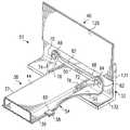
- FIG. 4is a schematic drawing showing an isometric view with portions broken away of a crosstie member having a weld attachment or weldment disposed on one end thereof and connected to a selected portion of a side sill in accordance with teachings of the present invention.
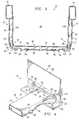
- FIG. 5is an isometric drawing showing an exploded view with portions broken away of the connection between the crosstie member and side sill of FIG. 4 .
- FIGS. 1-5 of the drawingslike numerals being used for like and corresponding parts of the various drawings.
- Railway car 20incorporating teachings of the present invention is shown in FIGS. 1 and 2.
- Railway car 20may be generally described as a “well car” satisfactory for carrying cargo containers (not expressly shown) used in intermodal transportation systems or other types of lading.
- railway car 20 incorporating teachings of the present inventionmay represent one unit of a multiple unit articulated well car.
- railway car 20may represent a single unit well car. Therefore, railway car 20 may include coupling assemblies and railway car trucks appropriate for an articulated railway car or alternatively coupling assemblies and trucks appropriate for a single unit well car.
- railway car 20may be designed to accommodate a single stack or a double stack of cargo containers.
- railway car or well car 20may represent one unit of a three unit articulated railway car (not expressly shown) having weld attachments formed in accordance with teachings of the present invention to connect a plurality of crossties with selected portions of associated side sills.
- well car 20may be designed to meet the requirements of the Association of American Railroads (AAR) Clearance Plate H plus one inch and associated structural design specifications.
- Well car 20may also be designed such that the lowest portion of well car 20 is no closer than two and three quarters of an inch above the top of the associated rails as determined by applicable AAR specifications.
- Railway car 20preferably includes end assemblies 21 and 22 with respective side assemblies 31 and 32 attached to and extending longitudinally between end assemblies 21 and 22 .
- End assemblies 21 and 22are mounted on respective railway car trucks 24 .
- Side assemblies 31 and 32are preferably spaced laterally from each other and extend generally parallel with each other between end assemblies 21 and 22 .
- Side assemblies 31 and 32cooperate with end assemblies 21 and 22 to define, in part, cargo carrying space 26 disposed therebetween. A portion of cargo carrying space 26 is depressed or extends below the normal floor level typically associated with a railway car having trucks 24 .
- the configuration and dimensions associated with end assemblies 21 and 22 and side assemblies 31 and 32are preferably selected to provide cargo carrying area 26 which is compatible with applicable overhead clearance limits and the type of containers or other lading which will be transported by railway car 20 .
- end assemblies 21 and 22 and side assemblies 31 and 32are attached to and/or from a portion of railway car underframe 28 .
- Two of these componentsinclude side sills 33 and 34 .
- a plurality of transverse memberssuch as load bearing cross members or crossbearers 36 and crossties 38 are preferably attached to and extend laterally between side sills 33 and 34 .
- Transverse members 36 and 38are preferably spaced longitudinally from each other and end assemblies 21 and 22 . The number, size and location of transverse members 36 and 38 is dependent upon the load carrying capacity and applicable AAR specifications for railway car 20 .
- Crossbearers 36often include one or more container supports and/or guides (not expressly shown) for securing one or more containers (not expressly shown) at a desired location within cargo space 26 .
- Side assemblies 31 and 32are preferably attached to and extend longitudinally along respective side sills 33 and 34 .
- a plurality of side stakes 40extend vertically from respective side sills 33 and 34 and top chords 41 and 42 .
- top chords 41 and 42may be described as hollow, elongated metal tubes having a generally rectangular cross section.
- side stakes 40may also be described as hollow, channels having a generally U-shaped cross section.
- the length of each side stake 40is defined in part by the distance between side sills 33 and 34 and respective top chords 41 and 42 .
- the wall or portion of each side stake 40 immediately adjacent to cargo space 26has been designated 126 .
- the wall or portion of each side stake 40 opposite from cargo space 26has been designated 127 .
- FIG. 3is a schematic drawing with portions broken away showing a cross section of side wall assemblies 31 and 32 along with one of the crossties 38 .
- the number, dimensions, configuration and materials used to form crossties 38are selected to provide desired structural support for the associated side sills 33 and 34 .
- Connections or weld attachments 51 and 52are preferably formed, in accordances with teachings of the present invention, between respective ends of each crosstie 38 and selected portions of side sills 33 and 34 .
- Connections 51 and 52 on each crosstie 38preferably have substantially the same configuration and dimensions. Therefore, only connection or weld attachment 51 will be discussed in detail.
- crosstie 38may be generally described as a hollow metal tube having a generally rectangular cross section.
- Respective end plates 50 incorporating teachings of the present inventionare preferably attached to opposite ends of crosstie 38 .
- each end plate 50is preferably attached to a selected portion of respective side sills 33 and 34 by mechanical fasteners and at least one weld.
- First surface or top surface 44 of crosstie 38extends between selected portions of side sills 33 and 34 .
- the length of top surface 44 plus the thickness of the associated end plate 50is approximately equal to the lateral distance between side sills 33 and 34 .
- Second surface or bottom surface 46 of crosstie 38is preferably reduced in length to allow respective press fittings 54 , with end plate 50 formed as an integral component thereof to be attached to the end of crosstie 38 .
- end plate 50may be formed as an integral part of a casting or forging (not expressly shown) having dimensions and a configuration corresponding generally with press fitting 54 .
- an end plate incorporating teachings of the present inventionmay be attached to a crosstie using various types of inserts, fasteners and welding procedures associated with the railway car manufacturing industry.
- crossties 38may be formed from an elongated strip of metal having a generally U-shaped cross section hereinafter referred to as U shaped channel 37 .
- Cover plate 39having a length less than the length of the associated crosstie 38 may be attached to the open portion of U-shaped channel 37 to provide second surface or bottom surface 46 .
- the length of the cover plate 39is preferably selected to be compatible with attaching respective press fittings 54 to opposite ends of crosstie 38 .
- crossties 38may be formed from hollow elongated metal tubes having a generally rectangular cross section. For the embodiment of the present invention [as] shown in FIGS.
- the elongated strip of metal used to form U shaped channel 37may have a thickness of approximately one-quarter of an inch.
- Cover plate 39may have a thickness of approximately three-sixteenths of an inch and press fittings 54 may have a thickness of approximately three-eighths of an inch.
- butt weld 56is preferably formed between end 47 of cover plate 39 and end 57 of press fitting 54 . See FIGS. 3 and 5.
- Backup bar 58is preferably disposed immediately adjacent to ends 47 and 57 to assist in forming butt weld 56 .
- notches 60are preferably formed in U shaped channel 37 at a location corresponding with the desired location for butt weld 56 .
- various manufacturing procedures and techniques associated with the railway car manufacturing industrymay be satisfactorily used to form a crosstie for use with the present invention.
- the present inventionis not limited to crossties 38 as shown in FIGS. 3, 4 and 5 .
- press fitting 54may be described as having a generally L-shaped configuration with end plate 50 formed as an integral part thereof.
- press fitting 54may be described as having a first leg 55 and a second leg extending therefrom which corresponds generally with end plate 50 .
- End 57 of first leg 55is preferably formed with dimensions corresponding generally with the dimensions of end 47 on cover plate 39 of crosstie 38 .
- the width of end 57 of press fitting 54is approximately equal to the width of the associated crosstie 38 .
- the width of end plate 50formed in accordance with teachings of the present invention is substantially larger than the width of the associated crosstie 38 .
- the width of first leg 55 of press fitting 54preferably increases substantially between end 57 and end plate 50 .
- first leg 55results in press fitting 54 having a generally flared configuration extending from crosstie 38 .
- a substantially larger weld 82may be formed as part of connection 51 .
- flaring the sides of first leg 55reduces or minimizes any effect of abruptness in the change in cross section between crosstie 38 and side sill 33 .
- side sills 33 and 34preferably have a generally L-shaped configuration.
- the respective legs of side sill 33have been designated 131 and 132 .
- the configuration of first leg 55 and end plate 50 of press fitting 54are preferably selected to be compatible with the configuration of legs 131 and 132 of side sill 33 .
- Enlargements 64 and 66are preferably formed on opposite sides of end plate 50 and spaced from the end of crosstie 38 .
- the dimensions and configuration of enlargements 64 and 66are preferably selected to be compatible with forming respective holes 78 and 80 therein to receive bolts 68 and 70 .
- Enlargements 64 and 66also cooperate with each other to form recessed area 77 extending therebetween.
- leg 131 of side sill 33preferably includes respective holes 108 and 110 which are sized to receive bolts 68 and 70 . Holes 108 and 110 are preferably formed at the selected location for forming connection 51 between crosstie 38 and side sill 33 .
- gussets 72 and 74are preferably attached to the exterior of crosstie 38 immediately adjacent to end plate 50 .
- gussets 72 and 74have an irregular configuration which somewhat resembles a triangle.
- Respective welds 76may be used to attach gussets 72 and 74 at the desired location on opposite sides of crosstie 38 adjacent to end plate 50 .
- Gussets 72 and 74are also preferably spaced from first leg 55 of press fitting 54 . Gussets 72 and 74 cooperate with each other to provide a generally flared or expanded cross section for crosstie 38 adjacent to end plate 50 and side sill 33 .
- crosstie 38 with press fitting 54 attached theretois preferably placed on leg 132 of crosstie 38 at the selected location.
- Mechanical fasteners 68 and 70may be placed through respective holes 78 and 80 in end plate 50 and holes 108 and 110 in side sill 33 .
- mechanical fasteners 68 and 70are bolts.
- other types of mechanical fastenerssuch as Huck® fasteners may be used instead of bolts.
- At least one weld 82may then be formed in recessed area 77 between enlargements 64 and 66 and adjacent portions of side sill 33 .
- Mechanical fasteners 68 and 70are preferably located proximate the ends of weld 82 in accordance with teachings of the present invention such that mechanical fasteners 68 and 70 will be subjected to fatigue cycling and loading before such loads are transferred to weld 82 .
- mechanical fasteners 68 and 70When loads are transferred between a first structural member and a second structural member, mechanical fasteners 68 and 70 preferably absorb or pick up a substantial portion of the load to be transferred before the load is applied to adjacent ends of weld 82 .
- mechanical fasteners 68 and 70substantially reduce peak stress at adjacent ends of weld 82 during load transfer between the first structural member and the second structural member.
- the size, location and configuration of holes 78 and 80are preferably selected such that mechanical fasteners 68 and 70 will be generally aligned with and disposed proximate to opposite ends of weld 82 .
- Mechanical fasteners 68 and 70are preferably loaded or torqued such that during movement of railway car 20 loads associated with fatigue cycling of the respective connection or weld attachment 51 will generally be transferred to mechanical fasteners 68 and 70 .
- end plate 50 and mechanical fasteners 68 and 70cooperate with each other to substantially reduce or eliminate fatigue cycling at the ends of weld 82 .
- the configuration of enlargement 64 and 66cooperate with recessed area 77 and mechanical fasteners 68 and 70 to minimize any stress risers at the end of weld 82 .
- the previously described flared or gradual change in cross section between crosstie 38 and adjacent portions of side sill 33 provided by first leg 55 and gussetts 72 and 74also helps reduce the magnitude of fatigue cycling and increases the life of connection or weld attachment 51 .
- the present inventionhas been described with respect to railway car 20 .
- an apparatus and methods incorporating teachings of the present inventionmay be used with a wide variety of railway cars used to carry freight and is not limited to well cars.
- methods and apparatuses incorporating teachings of the present inventionmay be used to form a weld attachment between any two structural members disposed at right angles when loads being transferred between the structural members may result in potential fatigue cracking.
Landscapes
- Engineering & Computer Science (AREA)
- Mechanical Engineering (AREA)
- Transportation (AREA)
- Connection Of Plates (AREA)
Abstract
Description
Claims (9)
Priority Applications (1)
| Application Number | Priority Date | Filing Date | Title |
|---|---|---|---|
| US09/551,244US6704991B1 (en) | 1999-10-20 | 2000-04-17 | Method for forming a railway car with improved crosstie connections |
Applications Claiming Priority (2)
| Application Number | Priority Date | Filing Date | Title |
|---|---|---|---|
| US16055299P | 1999-10-20 | 1999-10-20 | |
| US09/551,244US6704991B1 (en) | 1999-10-20 | 2000-04-17 | Method for forming a railway car with improved crosstie connections |
Publications (1)
| Publication Number | Publication Date |
|---|---|
| US6704991B1true US6704991B1 (en) | 2004-03-16 |
Family
ID=31949744
Family Applications (1)
| Application Number | Title | Priority Date | Filing Date |
|---|---|---|---|
| US09/551,244Expired - Fee RelatedUS6704991B1 (en) | 1999-10-20 | 2000-04-17 | Method for forming a railway car with improved crosstie connections |
Country Status (1)
| Country | Link |
|---|---|
| US (1) | US6704991B1 (en) |
Cited By (16)
| Publication number | Priority date | Publication date | Assignee | Title |
|---|---|---|---|---|
| US20050066852A1 (en)* | 2001-05-23 | 2005-03-31 | National Steel Car Limited | Well car with cross member |
| US20060076791A1 (en)* | 2004-10-07 | 2006-04-13 | Powers Robert G Jr | Retractable lading support |
| US20070284097A1 (en)* | 2006-06-08 | 2007-12-13 | Halliburton Energy Services, Inc. | Consumable downhole tools |
| US20080202764A1 (en)* | 2007-02-22 | 2008-08-28 | Halliburton Energy Services, Inc. | Consumable downhole tools |
| US20080257549A1 (en)* | 2006-06-08 | 2008-10-23 | Halliburton Energy Services, Inc. | Consumable Downhole Tools |
| US20090120324A1 (en)* | 2007-11-14 | 2009-05-14 | Gunderson Llc | Container car side sills |
| US20090158576A1 (en)* | 2006-03-01 | 2009-06-25 | Alexandre Pfleger | Method of assembling a drive member with a shaft coupled to the rotor of a rotating electrical machine |
| US7591318B2 (en) | 2006-07-20 | 2009-09-22 | Halliburton Energy Services, Inc. | Method for removing a sealing plug from a well |
| US8235102B1 (en) | 2008-03-26 | 2012-08-07 | Robertson Intellectual Properties, LLC | Consumable downhole tool |
| RU2457968C2 (en)* | 2009-02-05 | 2012-08-10 | Общество С Ограниченной Ответственностью "Головное Специализированное Конструкторское Бюро Вагоностроения" | Articulated car for haulage of large-capacity containers |
| US8327926B2 (en) | 2008-03-26 | 2012-12-11 | Robertson Intellectual Properties, LLC | Method for removing a consumable downhole tool |
| US8973508B2 (en) | 2013-01-18 | 2015-03-10 | National Steel Car Limited | Freight car with lifting location and method |
| US9249926B1 (en) | 2014-04-09 | 2016-02-02 | Valmont | Steel arm with internal tendon |
| RU193905U1 (en)* | 2019-06-27 | 2019-11-20 | Зао "Стрефа" | Platform carriage for combined transport |
| US12134412B2 (en) | 2020-12-22 | 2024-11-05 | National Steel Car Limited | Railroad well car structure |
| RU231813U1 (en)* | 2024-12-04 | 2025-02-11 | Акционерное общество "Рузаевский завод химического машиностроения" (АО "Рузхиммаш") | PLATFORM CAR |
Citations (16)
| Publication number | Priority date | Publication date | Assignee | Title |
|---|---|---|---|---|
| US874044A (en) | 1907-09-06 | 1907-12-17 | John W Addis | Body-bolster. |
| US1741188A (en) | 1928-02-27 | 1929-12-31 | George S Goodwin | Car frame |
| US4294439A (en)* | 1979-04-09 | 1981-10-13 | Mcintosh Corporation | Spring shackle |
| US4750431A (en) | 1987-05-07 | 1988-06-14 | Trinity Industries, Inc. | Offset side bearing structure for well car |
| US4782762A (en) | 1987-05-07 | 1988-11-08 | Trinity Industries, Inc. | Well car end girder arrangement |
| US4805539A (en) | 1987-05-07 | 1989-02-21 | Trinity Industries, Inc. | Well car end structure having frameless radial truck |
| US5054403A (en) | 1988-08-18 | 1991-10-08 | Gunderson, Inc. | Railroad freight car with well for stacked cargo containers |
| US5074725A (en) | 1990-12-20 | 1991-12-24 | Transit America, Inc. | Well car trailer adaptor |
| US5085152A (en) | 1989-11-22 | 1992-02-04 | Trinity Industries | Well car crossbearer side connection |
| US5279230A (en) | 1992-11-24 | 1994-01-18 | Gunderson, Inc. | Railroad well car body |
| US5423269A (en) | 1992-11-24 | 1995-06-13 | Gunderson, Inc. | Railroad well car body including side sill reinforcing walkway structure |
| US5465670A (en) | 1994-04-08 | 1995-11-14 | National Steel Car Limited | Railroad freight car having an improved structural support |
| US5562046A (en) | 1994-08-30 | 1996-10-08 | Trinity Industries, Inc. | Load bearing crossbearer connection |
| US5611285A (en) | 1992-11-24 | 1997-03-18 | Gunderson, Inc. | Multipurpose railraod well car |
| US5730063A (en) | 1996-04-30 | 1998-03-24 | National Steel Car Ltd. | High capacity container rail car for varying arrangements intermodal containers |
| US5918549A (en) | 1996-04-16 | 1999-07-06 | Trn Business Trust | Railway freight car metal floor |
- 2000
- 2000-04-17USUS09/551,244patent/US6704991B1/ennot_activeExpired - Fee Related
Patent Citations (17)
| Publication number | Priority date | Publication date | Assignee | Title |
|---|---|---|---|---|
| US874044A (en) | 1907-09-06 | 1907-12-17 | John W Addis | Body-bolster. |
| US1741188A (en) | 1928-02-27 | 1929-12-31 | George S Goodwin | Car frame |
| US4294439A (en)* | 1979-04-09 | 1981-10-13 | Mcintosh Corporation | Spring shackle |
| US4750431A (en) | 1987-05-07 | 1988-06-14 | Trinity Industries, Inc. | Offset side bearing structure for well car |
| US4782762A (en) | 1987-05-07 | 1988-11-08 | Trinity Industries, Inc. | Well car end girder arrangement |
| US4805539A (en) | 1987-05-07 | 1989-02-21 | Trinity Industries, Inc. | Well car end structure having frameless radial truck |
| US5054403A (en) | 1988-08-18 | 1991-10-08 | Gunderson, Inc. | Railroad freight car with well for stacked cargo containers |
| US5085152A (en) | 1989-11-22 | 1992-02-04 | Trinity Industries | Well car crossbearer side connection |
| US5074725A (en) | 1990-12-20 | 1991-12-24 | Transit America, Inc. | Well car trailer adaptor |
| US5279230A (en) | 1992-11-24 | 1994-01-18 | Gunderson, Inc. | Railroad well car body |
| US5379702A (en) | 1992-11-24 | 1995-01-10 | Gunderson, Inc. | Railroad well car including spacer for supporting a trailer |
| US5423269A (en) | 1992-11-24 | 1995-06-13 | Gunderson, Inc. | Railroad well car body including side sill reinforcing walkway structure |
| US5611285A (en) | 1992-11-24 | 1997-03-18 | Gunderson, Inc. | Multipurpose railraod well car |
| US5465670A (en) | 1994-04-08 | 1995-11-14 | National Steel Car Limited | Railroad freight car having an improved structural support |
| US5562046A (en) | 1994-08-30 | 1996-10-08 | Trinity Industries, Inc. | Load bearing crossbearer connection |
| US5918549A (en) | 1996-04-16 | 1999-07-06 | Trn Business Trust | Railway freight car metal floor |
| US5730063A (en) | 1996-04-30 | 1998-03-24 | National Steel Car Ltd. | High capacity container rail car for varying arrangements intermodal containers |
Non-Patent Citations (2)
| Title |
|---|
| File History on Patent Application 2,146,709 entitled A Retractable Guide Assembly For Changing The Effective Width of a Railroad Freight Car Container Well by National Steel Car Limited Filed Apr. 10, 1995. |
| Trinity Industries, Inc. Railcar Division Specification No. F-3-5741 "125 Ton Three Unit Articulated 53 Foot Well Car," pp. 1-15, Oct. 22, 1998. |
Cited By (32)
| Publication number | Priority date | Publication date | Assignee | Title |
|---|---|---|---|---|
| US20110185942A1 (en)* | 2001-05-23 | 2011-08-04 | National Steel Car Limited | Well car with cross member |
| US20080028975A1 (en)* | 2001-05-23 | 2008-02-07 | National Steel Car Limited | Well car with cross member |
| US7334528B2 (en)* | 2001-05-23 | 2008-02-26 | National Steel Car Limited | Well car with cross member |
| US8230792B2 (en)* | 2001-05-23 | 2012-07-31 | National Steel Car Limited | Well car with cross member |
| US7866267B2 (en)* | 2001-05-23 | 2011-01-11 | National Steel Car Limited | Well car with cross member |
| US20050066852A1 (en)* | 2001-05-23 | 2005-03-31 | National Steel Car Limited | Well car with cross member |
| US7497171B2 (en)* | 2001-05-23 | 2009-03-03 | National Steel Car Limited | Well car with cross member |
| US20090158958A1 (en)* | 2001-05-23 | 2009-06-25 | National Steel Car Limited | Well car with cross membr |
| US20060076791A1 (en)* | 2004-10-07 | 2006-04-13 | Powers Robert G Jr | Retractable lading support |
| US7370899B2 (en) | 2004-10-07 | 2008-05-13 | Tropicana Products, Inc. | Retractable lading support |
| US8434210B2 (en)* | 2006-03-01 | 2013-05-07 | Valeo Equipements Electriques Moteur | Method of assembling drive member with shaft coupled to rotor of rotating electrical machine |
| US20090158576A1 (en)* | 2006-03-01 | 2009-06-25 | Alexandre Pfleger | Method of assembling a drive member with a shaft coupled to the rotor of a rotating electrical machine |
| US8272446B2 (en) | 2006-06-08 | 2012-09-25 | Halliburton Energy Services Inc. | Method for removing a consumable downhole tool |
| US8256521B2 (en) | 2006-06-08 | 2012-09-04 | Halliburton Energy Services Inc. | Consumable downhole tools |
| US20070284097A1 (en)* | 2006-06-08 | 2007-12-13 | Halliburton Energy Services, Inc. | Consumable downhole tools |
| US8291970B2 (en) | 2006-06-08 | 2012-10-23 | Halliburton Energy Services Inc. | Consumable downhole tools |
| US20080257549A1 (en)* | 2006-06-08 | 2008-10-23 | Halliburton Energy Services, Inc. | Consumable Downhole Tools |
| US7591318B2 (en) | 2006-07-20 | 2009-09-22 | Halliburton Energy Services, Inc. | Method for removing a sealing plug from a well |
| US8056638B2 (en) | 2007-02-22 | 2011-11-15 | Halliburton Energy Services Inc. | Consumable downhole tools |
| US8322449B2 (en) | 2007-02-22 | 2012-12-04 | Halliburton Energy Services, Inc. | Consumable downhole tools |
| US20080202764A1 (en)* | 2007-02-22 | 2008-08-28 | Halliburton Energy Services, Inc. | Consumable downhole tools |
| US20100101803A1 (en)* | 2007-02-22 | 2010-04-29 | Halliburton Energy Services, Inc. | Consumable Downhole Tools |
| US7607396B2 (en)* | 2007-11-14 | 2009-10-27 | Gunderson Llc | Container car side sills |
| US20090120324A1 (en)* | 2007-11-14 | 2009-05-14 | Gunderson Llc | Container car side sills |
| US8327926B2 (en) | 2008-03-26 | 2012-12-11 | Robertson Intellectual Properties, LLC | Method for removing a consumable downhole tool |
| US8235102B1 (en) | 2008-03-26 | 2012-08-07 | Robertson Intellectual Properties, LLC | Consumable downhole tool |
| RU2457968C2 (en)* | 2009-02-05 | 2012-08-10 | Общество С Ограниченной Ответственностью "Головное Специализированное Конструкторское Бюро Вагоностроения" | Articulated car for haulage of large-capacity containers |
| US8973508B2 (en) | 2013-01-18 | 2015-03-10 | National Steel Car Limited | Freight car with lifting location and method |
| US9249926B1 (en) | 2014-04-09 | 2016-02-02 | Valmont | Steel arm with internal tendon |
| RU193905U1 (en)* | 2019-06-27 | 2019-11-20 | Зао "Стрефа" | Platform carriage for combined transport |
| US12134412B2 (en) | 2020-12-22 | 2024-11-05 | National Steel Car Limited | Railroad well car structure |
| RU231813U1 (en)* | 2024-12-04 | 2025-02-11 | Акционерное общество "Рузаевский завод химического машиностроения" (АО "Рузхиммаш") | PLATFORM CAR |
Similar Documents
| Publication | Publication Date | Title |
|---|---|---|
| US6704991B1 (en) | Method for forming a railway car with improved crosstie connections | |
| US7866267B2 (en) | Well car with cross member | |
| US20020073889A1 (en) | Cross member with container stop | |
| US4930427A (en) | Railroad gondola or hopper car, particularly a coal car | |
| US6584912B2 (en) | Well car structure | |
| CN102381330B (en) | Railway flatcar body with adaptive high weight concentration capacity | |
| US6978720B2 (en) | Gondola railcar construction | |
| US5054403A (en) | Railroad freight car with well for stacked cargo containers | |
| US5918549A (en) | Railway freight car metal floor | |
| US4893567A (en) | Railroad freight car with well for stacked cargo containers | |
| US5655792A (en) | Composite trailer and van type container assembly using bi-metal materials | |
| CN101715401B (en) | Railroad well car with open truss sides | |
| US6585466B2 (en) | Railcar anchor and load snugger arrangement | |
| US7654206B2 (en) | Container support casting for corner of container-carrying well car | |
| US20230249717A1 (en) | Railcar for transport of steel coils with removable bi-level roof | |
| US7607396B2 (en) | Container car side sills | |
| US20070137517A1 (en) | Railway Cars Manufactured With Self Piercing Rivets | |
| US20060207472A1 (en) | Railway cars with combined material structures and method | |
| US20240025460A1 (en) | Sill Connection for Railcar Structure | |
| CA2649051C (en) | Well car with cross member | |
| US3995564A (en) | Low level flat car | |
| US20030029353A1 (en) | Floor support connection casting | |
| CN116635313A (en) | Shipping container and method of making same | |
| CA2357841C (en) | Cross member with container stop | |
| CN116812005A (en) | A kind of chassis and multimodal transport vehicle |
Legal Events
| Date | Code | Title | Description |
|---|---|---|---|
| AS | Assignment | Owner name:TRN BUSINESS TRUST., TEXAS Free format text:ASSIGNMENT OF ASSIGNORS INTEREST;ASSIGNORS:COULBORN, JOHN W.;NGUYEN, DON P.;SMITH, STEPHEN W.;REEL/FRAME:010746/0309;SIGNING DATES FROM 20000217 TO 20000225 | |
| AS | Assignment | Owner name:TRN, INC.,TEXAS Free format text:MERGER;ASSIGNOR:TRN BUSINESS TRUST;REEL/FRAME:019204/0936 Effective date:20061220 Owner name:TRINITY INDUSTRIES, INC.,TEXAS Free format text:MERGER;ASSIGNOR:TRN, INC.;REEL/FRAME:019215/0206 Effective date:20061220 Owner name:TRINITY INDUSTRIES, INC., TEXAS Free format text:MERGER;ASSIGNOR:TRN, INC.;REEL/FRAME:019215/0206 Effective date:20061220 Owner name:TRN, INC., TEXAS Free format text:MERGER;ASSIGNOR:TRN BUSINESS TRUST;REEL/FRAME:019204/0936 Effective date:20061220 | |
| REMI | Maintenance fee reminder mailed | ||
| LAPS | Lapse for failure to pay maintenance fees | ||
| STCH | Information on status: patent discontinuation | Free format text:PATENT EXPIRED DUE TO NONPAYMENT OF MAINTENANCE FEES UNDER 37 CFR 1.362 | |
| FP | Lapsed due to failure to pay maintenance fee | Effective date:20080316 |