US6704564B1 - Method and system for controlling message transmission and acceptance by a telecommunications device - Google Patents
Method and system for controlling message transmission and acceptance by a telecommunications deviceDownload PDFInfo
- Publication number
- US6704564B1 US6704564B1US09/667,336US66733600AUS6704564B1US 6704564 B1US6704564 B1US 6704564B1US 66733600 AUS66733600 AUS 66733600AUS 6704564 B1US6704564 B1US 6704564B1
- Authority
- US
- United States
- Prior art keywords
- message
- dynamic logic
- logic expression
- telecommunications device
- service center
- Prior art date
- Legal status (The legal status is an assumption and is not a legal conclusion. Google has not performed a legal analysis and makes no representation as to the accuracy of the status listed.)
- Expired - Lifetime, expires
Links
Images


Classifications
- H—ELECTRICITY
- H04—ELECTRIC COMMUNICATION TECHNIQUE
- H04L—TRANSMISSION OF DIGITAL INFORMATION, e.g. TELEGRAPHIC COMMUNICATION
- H04L67/00—Network arrangements or protocols for supporting network services or applications
- H04L67/01—Protocols
- H04L67/12—Protocols specially adapted for proprietary or special-purpose networking environments, e.g. medical networks, sensor networks, networks in vehicles or remote metering networks
- H—ELECTRICITY
- H04—ELECTRIC COMMUNICATION TECHNIQUE
- H04L—TRANSMISSION OF DIGITAL INFORMATION, e.g. TELEGRAPHIC COMMUNICATION
- H04L67/00—Network arrangements or protocols for supporting network services or applications
- H04L67/50—Network services
- H04L67/52—Network services specially adapted for the location of the user terminal
- H—ELECTRICITY
- H04—ELECTRIC COMMUNICATION TECHNIQUE
- H04L—TRANSMISSION OF DIGITAL INFORMATION, e.g. TELEGRAPHIC COMMUNICATION
- H04L51/00—User-to-user messaging in packet-switching networks, transmitted according to store-and-forward or real-time protocols, e.g. e-mail
- H—ELECTRICITY
- H04—ELECTRIC COMMUNICATION TECHNIQUE
- H04L—TRANSMISSION OF DIGITAL INFORMATION, e.g. TELEGRAPHIC COMMUNICATION
- H04L69/00—Network arrangements, protocols or services independent of the application payload and not provided for in the other groups of this subclass
- H04L69/26—Special purpose or proprietary protocols or architectures
- H—ELECTRICITY
- H04—ELECTRIC COMMUNICATION TECHNIQUE
- H04L—TRANSMISSION OF DIGITAL INFORMATION, e.g. TELEGRAPHIC COMMUNICATION
- H04L69/00—Network arrangements, protocols or services independent of the application payload and not provided for in the other groups of this subclass
- H04L69/30—Definitions, standards or architectural aspects of layered protocol stacks
- H04L69/32—Architecture of open systems interconnection [OSI] 7-layer type protocol stacks, e.g. the interfaces between the data link level and the physical level
- H04L69/322—Intralayer communication protocols among peer entities or protocol data unit [PDU] definitions
- H04L69/329—Intralayer communication protocols among peer entities or protocol data unit [PDU] definitions in the application layer [OSI layer 7]
Definitions
- This inventionrelates to telecommunications systems, in general, and to a method and system for controlling transmission and acceptance of messages by a telecommunications device, in particular.
- Telematics systemsfrequently comprise telecommunications devices programmed to automatically send and receive messages under various conditions.
- Telematics systemsfor example (e.g.), General Motors Corporation's ONSTAR® system and Ford Motor Company's RESCU® system) are examples of such telecommunications systems.
- Telematicsgenerally refers to an emerging area of automotive/transportation communications technology that combines wireless voice and data to provide location-specific security, information, productivity and/or in-vehicle entertainment services to drivers and passengers.
- the typical telematics systemincludes a number of in-vehicle telematics devices that are connected wirelessly to a central service center.
- the in-vehicle telematics devicetypically includes various vehicle inputs that receive data relating to vehicle conditions (e.g., engine status, wiper status, air bag status, vehicle speed, et cetera (etc.)), an input to receive information relating to vehicle position (e.g., a Global Positioning System (GPS) receiver or GLObal NAvigation Satellite System (GLONASS) receiver), and a data/cellular transceiver.
- GPSGlobal Positioning System
- GLONASSGLObal NAvigation Satellite System
- the in-vehicle devicecommunicates location-specific information to the service center, and in turn the service center communicates with each in-vehicle device to control the in-vehicle device and deliver telematics services to the driver and/or passengers via a cellular telephone.
- Message filters and message triggersfacilitate such automated communications by telecommunications devices.
- Message triggerscontrol the transmission of messages by the telecommunications device by defining the conditions under which a message will be transmitted by the device.
- Message filtersdefine the conditions under which a message will be accepted by the device.
- telematics systemsutilize message triggers and message filters to facilitate automated communications between many vehicle-installed telematics devices and a service center. Telematics devices are typically programmed with various message triggers and filters associated with conditions under which the device will transmit and accept messages to and from the service center.
- the telematics function of compiling traffic information collected from vehicles having telematics devicesprovides an example of the use of message triggers and filters.
- telematics devices installed on vehiclescan be instructed by use of message triggers to send messages to a service center if the vehicle exceeds a certain speed or drops below a certain speed.
- the service centercan compile data relating to traffic conditions in the area.
- the service centercan provide instructions via messages to certain on-board telematics devices. On-board devices having data inputs satisfying certain specified conditions will accept a message transmitted by the service center, while telematics devices installed in other vehicles will filter the message so as not to process or respond to it.
- Telecommunications functionsoften require filters or triggers that are based on complex logical and arithmetic comparisons of combinations of two or more conditions.
- expressions defining combinations of conditions that will initiate communicationshave generally been preprogrammed into the telecommunications device. Configuration of the filters and triggers has typically been handled by instructing the device to apply one or more factory-programmed expressions.
- information desired from a telematics device reporting traffic informationmay vary widely depending upon a number of factors, such as, the vehicle's location or speed, the time of day, etc.
- FIG. 1illustrates a block diagram of a method and system for controlling message transmission by a telecommunications device in accordance with an embodiment of the invention
- FIG. 2illustrates a block diagram of an example of a method and system for controlling message transmission by a telematics device in accordance with an embodiment of the invention
- FIG. 3illustrates a block diagram of a first method and system for controlling acceptance of messages by a telecommunications device in accordance with an embodiment of the invention
- FIG. 4illustrates a block diagram of a second method and system for controlling acceptance of messages by a telecommunications device in accordance with an embodiment of the invention.
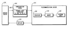
- FIG. 1outlines a method for controlling message transmission by a telecommunications device 110 .
- the telecommunications device 110can be any device that communicates by electronic transmission of signals.
- the telecommunications device 110preferably includes a memory 130 , a processor 190 programmed to carry out the functions described herein, and an external input 180 to provide data to the processor 190 via external sensors, devices or other inputs (not shown).
- external input 180can receive data from devices or sensors for detecting vehicle speed, vehicle position (e.g., GPS or GLONASS), engine status, air bag status, windshield wiper status, door lock status, cargo status, status of other vehicle systems, and vehicle properties (e.g., vehicle model and year).
- Data provided to the processor 190 via the external input 180preferably comprises data relating to conditions related to the transmission or acceptance of messages by the telecommunications device 110 .
- the telecommunications device 110is a telematics device.
- Telematics devicesinclude any vehicle communications device that combines wireless voice, data and/or location systems (e.g., GPS or GLONASS) to provide location-specific security, information, productivity and/or in-vehicle entertainment services to drivers and their passengers.
- Telematics systemsgenerally comprise a plurality of in-vehicle telematics devices wirelessly connected to a service center.
- the telematics devicegenerally communicates location-specific information to the service center, and in turn the service center communicates with the telematics device via a cellular telephone interface.
- Examples of telematics systemsinclude General Motors Corporation's ONSTAR® system and Ford Motor Company's RESCUE® system.
- FCDFloating Car Data
- telematics devices providing FCD servicefrequently check certain conditions, based on the sensors available to the device (e.g., vehicle location and speed). If defined threshold values are passed, a message is sent to a service center.
- This messagecontains data that allows the service center to deduct information about the traffic flow in the vehicle's vicinity.
- telematics devices installed on vehicles at a particular locationcan be instructed by use of message triggers to send messages to a service center if the vehicle exceeds a certain speed or drops below a certain speed.
- the service centercan compile data relating to traffic conditions.
- FCDFibre Channel Determination
- a vehiclemight report too often or too rarely, or it might report under wrong conditions, thus adding little or no value to the service center's traffic information. It is therefore preferred that an FCD system be kept as flexible as possible.
- the method described hereincan be applied to other telecommunications and telematics applications, for example, remote vehicle/equipment diagnostics, fleet management, and individual health watch (e.g., blood pressure monitors and the like).
- a trigger configuration signal 150is transmitted to the telecommunications device 110 and preferably stored in memory 130 .
- the trigger configuration signal 150is an electronic message that instructs the telecommunications device 110 as to the triggers or combination of triggers to be applied at a given time.
- Each message triggeris an expression that defines one or more conditions that must be satisfied for the telecommunications device 110 to transmit a message 140 to a service center 170 .
- the conditionsare preferably based upon fixed parameters (e.g., vehicle or system properties) or dynamic values (e.g., speed, temperature, system status, or position) available to the telecommunications device 110 via sensors and/or other data input.
- the trigger configuration signal 150comprises a dynamic logic expression 160 preferably having one or more operands (F 1 , F 2 and F 3 ). Each of the operands preferably defines a condition associated with the transmission of a message.
- a dynamic logic expressionis a logic expression that can be modified by changing operators and operands.
- the dynamic logic expression 160is preferably a Boolean expression.
- the logic expressionis dynamic, and both operators and operands can preferably be continuously changed to allow many or all logical combinations of available triggers.
- the dynamic logic expression 160is (F 1 AND F 3 ) OR F 2 .
- Application of this expressionresults in a message being sent if the dynamic logic expression yields a TRUE result.
- the logic expressionis dynamic, it can be modified by changing operators and/or operands. For example, a different trigger configuration signal could be sent to modify the dynamic logic expression to (F 2 OR F 4 ) AND F 6 . This new dynamic logic expression changes the trigger configuration.
- the operands of the dynamic logic expressionpreferably comprise sub-expressions defining conditions associated with the transmission of a message.
- the operandsare typically arithmetic expressions, comparisons or functions relating to such data.
- F 1could be “Speed(t 1 )>50,” where “Speed(t 1 )” refers to a fixed association with an in-vehicle sensor recording in memory, where “(t 1 ) designates the position in memory where a historic speed value can be found and “Speed” is a function having time as a parameter.
- the symbol “>”is the comparison operator and “50” is a threshold value to be applied.
- Expressions defining conditions associated with the transmission of a messagecan be simple expressions or can be based on complex logical and arithmetic functions.
- telematics systemstypically include a number of vehicle and system interfaces that provide data to a telematics controller unit relating to traffic, weather, location or vehicle conditions, for example, vehicle speed, vehicle location (e.g., GPS or GLONASS data), status of vehicle systems (e.g., engine, windshield wipers, air bags, door locks, etc.), and vehicle properties (e.g., vehicle model and year). Time is also frequently a component of expressions defining conditions associated with the transmission of a message.
- Conditions defining conditions associated with the transmission of a messagemay include more complex arithmetic expressions, such as, for example, average, maximum, minimum, etc.
- the trigger configuration signal 150is transmitted from a service center 170 that communicates with a plurality of telecommunications devices.
- a service centeris a communications center that sends and receives electronic messages from a plurality of telecommunications devices.
- the telecommunications device 110receives the trigger configuration signal 150 and preferably stores the trigger configuration signal in the memory 130 .
- the dynamic logic expression 160 of the trigger configuration signal 150is applied by telecommunications device 110 , and a message 140 is transmitted by the telecommunications device 110 if the dynamic logic expression 160 is satisfied.
- the dynamic logic expression 160is preferably interpreted and applied by the processor 190 using an expression interpreter programmed in the telecommunications device 110 .
- the processor 190preferably receives data relating to conditions associated with message transmission from the external input 180 and/or memory 130 .
- the message 140is preferably transmitted by the telecommunications device 110 and received by a service center 170 that communicates with a plurality of telecommunications devices.
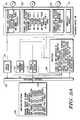
- FIG. 2outlines an example of a method and system for controlling transmission of messages by a telematics device 210 .
- the telematics device 210preferably includes a wireless transceiver 220 that receives a configuration signal 250 from a service center (not shown).
- the configuration signal 250preferably comprises a command instructing the device to update its trigger configuration.
- the commandpreferably specifies a particular telematics functions to which the trigger configuration signal applies (e.g., traffic reporting, fleet management, vehicle diagnostics, etc.).
- the configuration signal 250comprises a dynamic logic expression 262 .
- the configuration signal 250instructs the telematics device 210 to update a trigger configuration so as to transmit a message relating to fleet management if the dynamic logic expression 262 is satisfied.
- the telematics device 210preferably can be controlled using one or more dynamic logic expressions 261 - 263 .
- Each of dynamic logic expressions 261 - 263is associated with a different telematics function (e.g., traffic reporting, fleet management, and vehicle diagnostics).
- Dynamic logic expression 263relates to vehicle diagnostics and comprises the following expression: “If (OIL_TEMPERATURE>150).” A message is transmitted by the telematics device 210 relating to the applicable telematics function if the dynamic logic expression associated with that function is satisfied.
- Processor 290preferably stores the dynamic logic expressions 261 - 263 in a nonvolatile memory 231 overwriting any previous dynamic logic expression stored in the memory location allocated for the dynamic logic expression associated with the telematics function to which the new dynamic logic expression pertains.
- processor 290can detect that an additional memory area is needed for the evaluation of a dynamic logic expression 261 - 263 , and allocate enlarged history required by the expression.
- Processor 290preferably parses and evaluates in intervals dynamic logic expressions 261 - 263 . If any of the expressions yields a “TRUE” result, a message 241 - 243 , preferably associated with the applicable telematics function, is sent to a service center (not shown). Processor 290 preferably evaluates dynamic logic expressions 261 - 263 using data stored in a volatile memory 232 . In the example shown in FIG. 2, the data comprises information relating to vehicle speed, oil temperature, light status, vehicle position, vehicle model and year. The data stored in volatile memory 232 is preferably input via external input 280 .
- external input 280comprises vehicle internal information system 281 , positioning system (e.g., GPS or GLONASS) 282 , and vehicle stored properties 285 .
- Vehicle internal information system 281preferably comprises sensors (not shown) that collect data relating to internal vehicle systems (e.g., equipment temperature, equipment status, vehicle speed, etc.).
- Positioning system 282preferably comprises a positioning system receiver (not shown) that collects data relating to the vehicle's position.
- Vehicle stored properties 285preferably inputs data relating to vehicle properties (e.g., vehicle model, vehicle model year, etc.).
- Volatile memory 232preferably comprises memory locations storing current external input values 234 and accumulated values 233 . Accumulated values 233 facilitate evaluation of arithmetic functions contained within the dynamic logic expressions (e.g., computing average vehicle speed or determining the direction in which the vehicle is traveling) by temporarily storing historical data.
- the method described hereincan also be applied to control input of telecommunications devices through configuration of message filters that define required conditions for a telecommunications device to accept a message.
- Message filterspreferably facilitate the transmission of messages to a plurality of telecommunications devices where it is desired that only a portion of the devices accept and process particular messages.
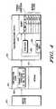
- FIG. 3outlines a method and system for controlling acceptance of messages by a telecommunications device 310 .
- the telecommunications devicepreferably includes a memory 330 and a processor 390 programmed to carry out the functions described herein.
- a message filter configuration signal 350is transmitted to the telecommunications device 310 .
- the message filter configuration signal 350comprises a dynamic logic expression 360 defining one or more conditions associated with the acceptance of a message.
- the dynamic logic expressionpreferably has one or more operands, each of the operands defining a condition associated with the acceptance of a message.
- the dynamic logic expression 360is received by telecommunications device 310 and preferably stored in memory 330 .
- a message 340is also transmitted to the telecommunications device 310 and preferably stored in memory 330 .
- the configuration signal 350is transmitted with message 340 .
- the configuration signal 350can be transmitted before message 340 .
- the dynamic logic expression 360is interpreted and applied, preferably by processor 390 utilizing data relating to conditions associated with the acceptance of a message input to the processor 390 via an external input 380 and/or memory 330 .
- the message 340is accepted by the telecommunications device 310 if the dynamic logic expression 360 is satisfied.
- acceptmeans to receive and process the content of a message. If the configuration signal 350 is transmitted with the message 340 , both the configuration signal 350 and the message 340 will preferably be received by the telecommunications device 310 . The message 340 will be processed and acted upon if the dynamic logic expression 360 is satisfied. If the dynamic logic expression 360 is not satisfied, the message 340 will be ignored or discarded.
- Message filter configuration signalsare preferably transmitted along with associated messages. If the expression yields a TRUE result, the telecommunications device would accept the associated message, if FALSE, the telecommunications device would ignore the message. Different filter configuration signals can be sent to modify the dynamic logic expression to change the filter configuration.
- the message filter configuration signal 350is preferably transmitted from a service center 370 that communicates with a plurality of telecommunications devices.
- the message 340is preferably transmitted to the telecommunications device 310 from a service center 370 that communicates with a plurality of telecommunications devices.
- the telecommunications device 310is a telematics device, and the message 340 transmitted to the telematics device comprises information exchanged between the telematics device and the service center.
- FIG. 4outlines an alternative embodiment of the method and system for controlling a telecommunications device 410 using one or more expressions 421 - 426 stored in memory 430 .
- the telecommunications devicepreferably includes a processor 490 programmed to carry out the functions described herein.
- one or more expressions 421 - 426each defining a condition associated with the acceptance of a message are stored in memory 430 .
- a message filter configuration signal 450is transmitted to the telecommunications device 410 .
- the message filter configuration signal 450comprises a dynamic logic expression 460 preferably having one or more operands, each of the operands designating a location in memory for one of the expressions 421 - 426 .
- the dynamic logic expression 460is received by telecommunications device 410 and preferably stored in memory 430 .
- a message 440is also transmitted to the telecommunications device 410 and preferably stored in memory 430 .
- the configuration signal 450is transmitted with message 440 .
- the configuration signal 450can be transmitted before message 440 .
- the dynamic logic expression 460is interpreted and applied, preferably by processor 490 utilizing data relating to conditions associated with the acceptance of a message input to the processor 490 via an external input 480 and/or memory 430 .
- the message 440is accepted by the telecommunications device 410 if the dynamic logic expression 460 is satisfied.
- the message filter configuration signal 450is preferably transmitted from a service center 470 that communicates with a plurality of telecommunications devices.
- the message 440is preferably transmitted to the telecommunications device 410 from a service center 470 that communicates with a plurality of telecommunications devices.
- an improved method and system for controlling a telecommunications deviceis provided to overcome the disadvantages of the prior art.
- Systems and devices utilizing the methods described hereinare not limited by the preprogramming of the telecommunications device.
- the method and system described hereinallows deployed telecommunications devices to be remotely reconfigured with numerous logical combinations of available filters and triggers.
- the problem of updating filters and triggers using a narrow-bandwidth signaling channelcan be overcome by transmitting the expression itself, thus providing great flexibility in controlling the behavior of already deployed telecommunications devices.
- By transmitting dynamic expressions to telecommunications devicesthe behavior of the device can be changed without requiring the customer to visit a dealership or a service center.
- the range of possible changes compared to existing solutionsis significantly enlarged. Service quality can be raised, and service maintenance and operations can be reduced.
- new servicescan be provided by already deployed telecommunications devices by enlarging the variety of triggers and filters available.
Landscapes
- Engineering & Computer Science (AREA)
- Computer Networks & Wireless Communication (AREA)
- Signal Processing (AREA)
- Health & Medical Sciences (AREA)
- Computing Systems (AREA)
- General Health & Medical Sciences (AREA)
- Medical Informatics (AREA)
- Telephonic Communication Services (AREA)
- Mobile Radio Communication Systems (AREA)
Abstract
Description
Claims (25)
Priority Applications (2)
| Application Number | Priority Date | Filing Date | Title |
|---|---|---|---|
| US09/667,336US6704564B1 (en) | 2000-09-22 | 2000-09-22 | Method and system for controlling message transmission and acceptance by a telecommunications device |
| DE10146898ADE10146898B4 (en) | 2000-09-22 | 2001-09-24 | A method and system for controlling the transmission and acceptance of messages by a telecommunications device |
Applications Claiming Priority (1)
| Application Number | Priority Date | Filing Date | Title |
|---|---|---|---|
| US09/667,336US6704564B1 (en) | 2000-09-22 | 2000-09-22 | Method and system for controlling message transmission and acceptance by a telecommunications device |
Publications (1)
| Publication Number | Publication Date |
|---|---|
| US6704564B1true US6704564B1 (en) | 2004-03-09 |
Family
ID=24677815
Family Applications (1)
| Application Number | Title | Priority Date | Filing Date |
|---|---|---|---|
| US09/667,336Expired - LifetimeUS6704564B1 (en) | 2000-09-22 | 2000-09-22 | Method and system for controlling message transmission and acceptance by a telecommunications device |
Country Status (2)
| Country | Link |
|---|---|
| US (1) | US6704564B1 (en) |
| DE (1) | DE10146898B4 (en) |
Cited By (20)
| Publication number | Priority date | Publication date | Assignee | Title |
|---|---|---|---|---|
| US20020151297A1 (en)* | 2000-10-14 | 2002-10-17 | Donald Remboski | Context aware wireless communication device and method |
| US20030078865A1 (en)* | 2001-10-24 | 2003-04-24 | Lee Theodore C. | Automated financial market information and trading system |
| US20030231550A1 (en)* | 2002-06-13 | 2003-12-18 | General Motors Corporation | Personalized key system for a mobile vehicle |
| US20040142659A1 (en)* | 2002-04-03 | 2004-07-22 | Oesterling Christopher L. | Method and system for initiating a vehicle data upload function at a plurality of mobile vehicles |
| US20060064573A1 (en)* | 2001-05-17 | 2006-03-23 | Accenture Global Services Gmbh | Pipeline architecture for use with net-centric application program architectures |
| US20060095503A1 (en)* | 2002-12-26 | 2006-05-04 | Hiroyuki Kanza | Information processor, mobile terminal, information processing system, information processing method, information processing program, and computer-readable recorded medium |
| US20060129309A1 (en)* | 2004-12-14 | 2006-06-15 | International Business Machines Corporation | Method and system for performing programmatic actions based upon vehicle approximate locations |
| US20070082679A1 (en)* | 2005-09-29 | 2007-04-12 | Chul-Su Kim | Telematics transport gateway and operating method thereof |
| EP1912191A1 (en)* | 2006-10-12 | 2008-04-16 | Aisin AW Co., Ltd. | Navigation system |
| US20110144911A1 (en)* | 2009-12-11 | 2011-06-16 | General Motors Company | Method of processing global navigation satellite system data |
| US20140201748A1 (en)* | 2013-01-11 | 2014-07-17 | General Motors Llc | Telematics control utilizing relational formulas |
| US20150193219A1 (en)* | 2014-01-09 | 2015-07-09 | Ford Global Technologies, Llc | Flexible feature deployment strategy |
| US9340214B2 (en) | 2014-04-14 | 2016-05-17 | Caterpillar Inc. | System for remotely controlling a machine |
| US20170048711A1 (en)* | 2003-01-28 | 2017-02-16 | Cellport Systems, Inc. | Secure telematics |
| US9716762B2 (en) | 2014-03-31 | 2017-07-25 | Ford Global Technologies Llc | Remote vehicle connection status |
| US9766874B2 (en) | 2014-01-09 | 2017-09-19 | Ford Global Technologies, Llc | Autonomous global software update |
| US10140110B2 (en) | 2014-04-02 | 2018-11-27 | Ford Global Technologies, Llc | Multiple chunk software updates |
| US20220180734A1 (en)* | 2012-02-16 | 2022-06-09 | Appy Risk Technologies Limited | Traffic portal enquiry and alert system |
| US20240217320A1 (en)* | 2022-12-30 | 2024-07-04 | Rivian Ip Holdings, Llc | Vehicle gear door |
| DE112020007654B4 (en) | 2020-12-04 | 2024-10-10 | Mitsubishi Electric Corporation | server device, control circuit, storage medium and traffic support method |
Citations (23)
| Publication number | Priority date | Publication date | Assignee | Title |
|---|---|---|---|---|
| US5311197A (en) | 1993-02-01 | 1994-05-10 | Trimble Navigation Limited | Event-activated reporting of vehicle location |
| US5420794A (en)* | 1993-06-30 | 1995-05-30 | James; Robert D. | Automated highway system for controlling the operating parameters of a vehicle |
| US5673305A (en) | 1993-05-14 | 1997-09-30 | Worldwide Notification Systems, Inc. | Apparatus and method for tracking and reporting the location of a motor vehicle |
| US5699056A (en) | 1994-12-28 | 1997-12-16 | Omron Corporation | Traffic information system |
| US6012012A (en) | 1995-03-23 | 2000-01-04 | Detemobil Deutsche Telekom Mobilnet Gmbh | Method and system for determining dynamic traffic information |
| US6023654A (en) | 1996-03-25 | 2000-02-08 | Mannesmann Aktiengesellschaft | Method for referencing fixed objects |
| US6028537A (en) | 1996-06-14 | 2000-02-22 | Prince Corporation | Vehicle communication and remote control system |
| JP2000123291A (en)* | 1998-10-16 | 2000-04-28 | Nokia Mobile Phones Ltd | Method and device for selecting traffic information for vehicle |
| US6061625A (en) | 1996-02-08 | 2000-05-09 | Mannesmann Ag | Process for obtaining traffic data |
| US6092020A (en) | 1996-02-08 | 2000-07-18 | Mannesmann Ag | Method and apparatus for obtaining traffic situation data |
| US6107917A (en)* | 1998-10-16 | 2000-08-22 | Carrender; Curtis L. | Electronic tag including RF modem for monitoring motor vehicle performance with filtering |
| US6112152A (en)* | 1996-12-06 | 2000-08-29 | Micron Technology, Inc. | RFID system in communication with vehicle on-board computer |
| US20010014863A1 (en)* | 2000-01-31 | 2001-08-16 | Williams Lawrence E. | Methods and systems for providing life management and enhancement applications and services for telematics and other electronic medium |
| US6282491B1 (en)* | 1996-10-02 | 2001-08-28 | Robert Bosch Gmbh | Telematic device for a motor vehicle |
| US6370452B1 (en)* | 1999-12-08 | 2002-04-09 | Samuel T. Pfister | Autonomous vehicle transit system |
| US6405361B1 (en)* | 1998-08-20 | 2002-06-11 | Manfred Broy | Automatically generating a program |
| US6430555B1 (en)* | 1996-10-16 | 2002-08-06 | Mannesmann Ag | Method and device for data transmission between a central unit and a data terminal |
| US6459967B1 (en)* | 1998-08-28 | 2002-10-01 | Robert Bosch Gmbh | Device for controlling and monitoring a vehicle |
| US20020140545A1 (en)* | 2000-08-18 | 2002-10-03 | Peter Nietupski | Integrated RKE and telematics system |
| US6505100B1 (en)* | 1999-03-02 | 2003-01-07 | Daimlerchrysler Ag | Distributed vehicle information processing and vehicle control system |
| US6526460B1 (en)* | 1998-08-28 | 2003-02-25 | Daimlerchrysler Ag | Vehicle communications system |
| US6526268B1 (en)* | 1999-09-07 | 2003-02-25 | Delphi Technologies, Inc. | Mobile weather band radio and method |
| US6633784B1 (en)* | 1999-10-28 | 2003-10-14 | General Electric Corporation | Configuration of a remote data collection and communication system |
Family Cites Families (1)
| Publication number | Priority date | Publication date | Assignee | Title |
|---|---|---|---|---|
| US5959529A (en)* | 1997-03-07 | 1999-09-28 | Kail, Iv; Karl A. | Reprogrammable remote sensor monitoring system |
- 2000
- 2000-09-22USUS09/667,336patent/US6704564B1/ennot_activeExpired - Lifetime
- 2001
- 2001-09-24DEDE10146898Apatent/DE10146898B4/ennot_activeExpired - Lifetime
Patent Citations (24)
| Publication number | Priority date | Publication date | Assignee | Title |
|---|---|---|---|---|
| US5311197A (en) | 1993-02-01 | 1994-05-10 | Trimble Navigation Limited | Event-activated reporting of vehicle location |
| US5673305A (en) | 1993-05-14 | 1997-09-30 | Worldwide Notification Systems, Inc. | Apparatus and method for tracking and reporting the location of a motor vehicle |
| US5420794A (en)* | 1993-06-30 | 1995-05-30 | James; Robert D. | Automated highway system for controlling the operating parameters of a vehicle |
| US5699056A (en) | 1994-12-28 | 1997-12-16 | Omron Corporation | Traffic information system |
| US6012012A (en) | 1995-03-23 | 2000-01-04 | Detemobil Deutsche Telekom Mobilnet Gmbh | Method and system for determining dynamic traffic information |
| US6092020A (en) | 1996-02-08 | 2000-07-18 | Mannesmann Ag | Method and apparatus for obtaining traffic situation data |
| US6061625A (en) | 1996-02-08 | 2000-05-09 | Mannesmann Ag | Process for obtaining traffic data |
| US6023654A (en) | 1996-03-25 | 2000-02-08 | Mannesmann Aktiengesellschaft | Method for referencing fixed objects |
| US6028537A (en) | 1996-06-14 | 2000-02-22 | Prince Corporation | Vehicle communication and remote control system |
| US6282491B1 (en)* | 1996-10-02 | 2001-08-28 | Robert Bosch Gmbh | Telematic device for a motor vehicle |
| US6430555B1 (en)* | 1996-10-16 | 2002-08-06 | Mannesmann Ag | Method and device for data transmission between a central unit and a data terminal |
| US6112152A (en)* | 1996-12-06 | 2000-08-29 | Micron Technology, Inc. | RFID system in communication with vehicle on-board computer |
| US6405361B1 (en)* | 1998-08-20 | 2002-06-11 | Manfred Broy | Automatically generating a program |
| US6459967B1 (en)* | 1998-08-28 | 2002-10-01 | Robert Bosch Gmbh | Device for controlling and monitoring a vehicle |
| US6526460B1 (en)* | 1998-08-28 | 2003-02-25 | Daimlerchrysler Ag | Vehicle communications system |
| US6266608B1 (en)* | 1998-10-16 | 2001-07-24 | Nokia Mobile Phones Limited | Method and apparatus for the selection of traffic information for a motor vehicle |
| US6107917A (en)* | 1998-10-16 | 2000-08-22 | Carrender; Curtis L. | Electronic tag including RF modem for monitoring motor vehicle performance with filtering |
| JP2000123291A (en)* | 1998-10-16 | 2000-04-28 | Nokia Mobile Phones Ltd | Method and device for selecting traffic information for vehicle |
| US6505100B1 (en)* | 1999-03-02 | 2003-01-07 | Daimlerchrysler Ag | Distributed vehicle information processing and vehicle control system |
| US6526268B1 (en)* | 1999-09-07 | 2003-02-25 | Delphi Technologies, Inc. | Mobile weather band radio and method |
| US6633784B1 (en)* | 1999-10-28 | 2003-10-14 | General Electric Corporation | Configuration of a remote data collection and communication system |
| US6370452B1 (en)* | 1999-12-08 | 2002-04-09 | Samuel T. Pfister | Autonomous vehicle transit system |
| US20010014863A1 (en)* | 2000-01-31 | 2001-08-16 | Williams Lawrence E. | Methods and systems for providing life management and enhancement applications and services for telematics and other electronic medium |
| US20020140545A1 (en)* | 2000-08-18 | 2002-10-03 | Peter Nietupski | Integrated RKE and telematics system |
Cited By (32)
| Publication number | Priority date | Publication date | Assignee | Title |
|---|---|---|---|---|
| US20020151297A1 (en)* | 2000-10-14 | 2002-10-17 | Donald Remboski | Context aware wireless communication device and method |
| US20060064573A1 (en)* | 2001-05-17 | 2006-03-23 | Accenture Global Services Gmbh | Pipeline architecture for use with net-centric application program architectures |
| US20030078865A1 (en)* | 2001-10-24 | 2003-04-24 | Lee Theodore C. | Automated financial market information and trading system |
| US20040142659A1 (en)* | 2002-04-03 | 2004-07-22 | Oesterling Christopher L. | Method and system for initiating a vehicle data upload function at a plurality of mobile vehicles |
| US8406683B2 (en)* | 2002-04-03 | 2013-03-26 | General Motors Llc | Method and system for initiating a vehicle data upload function at a plurality of mobile vehicles |
| US20030231550A1 (en)* | 2002-06-13 | 2003-12-18 | General Motors Corporation | Personalized key system for a mobile vehicle |
| US7548491B2 (en)* | 2002-06-13 | 2009-06-16 | General Motors Corporation | Personalized key system for a mobile vehicle |
| US20060095503A1 (en)* | 2002-12-26 | 2006-05-04 | Hiroyuki Kanza | Information processor, mobile terminal, information processing system, information processing method, information processing program, and computer-readable recorded medium |
| US20190166494A1 (en)* | 2003-01-28 | 2019-05-30 | Cybercar Inc. | Secure telematics |
| US10231125B2 (en)* | 2003-01-28 | 2019-03-12 | Cybercar Inc. | Secure telematics |
| US20170048711A1 (en)* | 2003-01-28 | 2017-02-16 | Cellport Systems, Inc. | Secure telematics |
| US20090150070A1 (en)* | 2004-12-14 | 2009-06-11 | International Business Machines Corporation | Method and system for performing programmatic actions based upon vehicle appropximate locations |
| US20060129309A1 (en)* | 2004-12-14 | 2006-06-15 | International Business Machines Corporation | Method and system for performing programmatic actions based upon vehicle approximate locations |
| US7912630B2 (en)* | 2004-12-14 | 2011-03-22 | International Business Machines Corporation | Method and system for performing programmatic actions based upon vehicle approximate locations |
| US20070082679A1 (en)* | 2005-09-29 | 2007-04-12 | Chul-Su Kim | Telematics transport gateway and operating method thereof |
| EP1912191A1 (en)* | 2006-10-12 | 2008-04-16 | Aisin AW Co., Ltd. | Navigation system |
| US8364391B2 (en)* | 2006-10-12 | 2013-01-29 | Aisin Aw Co., Ltd. | Navigation system |
| US20080091339A1 (en)* | 2006-10-12 | 2008-04-17 | Aisin Aw Co., Ltd. | Navigation system |
| CN101162551B (en)* | 2006-10-12 | 2011-07-27 | 爱信艾达株式会社 | Navigation system |
| US9200902B2 (en) | 2009-12-11 | 2015-12-01 | General Motors Llc | Method of processing global navigation satellite system data |
| US20110144911A1 (en)* | 2009-12-11 | 2011-06-16 | General Motors Company | Method of processing global navigation satellite system data |
| US20220180734A1 (en)* | 2012-02-16 | 2022-06-09 | Appy Risk Technologies Limited | Traffic portal enquiry and alert system |
| US9086915B2 (en)* | 2013-01-11 | 2015-07-21 | General Motors Llc | Telematics control utilizing relational formulas |
| US20140201748A1 (en)* | 2013-01-11 | 2014-07-17 | General Motors Llc | Telematics control utilizing relational formulas |
| US9524156B2 (en)* | 2014-01-09 | 2016-12-20 | Ford Global Technologies, Llc | Flexible feature deployment strategy |
| US20150193219A1 (en)* | 2014-01-09 | 2015-07-09 | Ford Global Technologies, Llc | Flexible feature deployment strategy |
| US9766874B2 (en) | 2014-01-09 | 2017-09-19 | Ford Global Technologies, Llc | Autonomous global software update |
| US9716762B2 (en) | 2014-03-31 | 2017-07-25 | Ford Global Technologies Llc | Remote vehicle connection status |
| US10140110B2 (en) | 2014-04-02 | 2018-11-27 | Ford Global Technologies, Llc | Multiple chunk software updates |
| US9340214B2 (en) | 2014-04-14 | 2016-05-17 | Caterpillar Inc. | System for remotely controlling a machine |
| DE112020007654B4 (en) | 2020-12-04 | 2024-10-10 | Mitsubishi Electric Corporation | server device, control circuit, storage medium and traffic support method |
| US20240217320A1 (en)* | 2022-12-30 | 2024-07-04 | Rivian Ip Holdings, Llc | Vehicle gear door |
Also Published As
| Publication number | Publication date |
|---|---|
| DE10146898A1 (en) | 2002-05-29 |
| DE10146898B4 (en) | 2007-02-15 |
Similar Documents
| Publication | Publication Date | Title |
|---|---|---|
| US6704564B1 (en) | Method and system for controlling message transmission and acceptance by a telecommunications device | |
| US11741840B2 (en) | Identifying roadway obstacles based on vehicular data | |
| US6604038B1 (en) | Apparatus, method, and computer program product for establishing a remote data link with a vehicle with minimal data transmission delay | |
| EP1723612B1 (en) | Vehicle telematics system | |
| US11708037B2 (en) | Vehicle control device and wireless communication network | |
| US20090259349A1 (en) | Delivering commands to a vehicle | |
| EP3341924A1 (en) | Devices systems and methods for vehicle monitoring and platooning | |
| US20140240143A1 (en) | Vehicle monitoring system and device | |
| EP2330580A1 (en) | Vehicle parking locator system and method using connected vehicles | |
| DE102017107787A1 (en) | Intersection assistance systems and methods using dedicated short-range communication | |
| AU2005280609A1 (en) | Systems and methods for radio frequency trigger | |
| US7116245B1 (en) | Method and system for beacon/heading emergency vehicle intersection preemption | |
| US11572067B2 (en) | Using ISA system to decelerate truck upon entering geofenced area | |
| EP4261717A2 (en) | Systems and methods for communicating with third parties external to autonomous vehicles | |
| CN112566829A (en) | Operating method for autonomous driving vehicle | |
| US20170168484A1 (en) | Method for transmitting, receiving and processing data values, and a transmission device and receiving device | |
| US20240416922A1 (en) | Real-time driver analysis and notification system | |
| CN115547089A (en) | Tracker application based on V2X messages | |
| US11797015B2 (en) | Method and system for determining a target vehicle speed of a vehicle operating at a worksite | |
| US9463799B1 (en) | Control for a high or fully automatic driving function | |
| EP3291203A1 (en) | Method for providing warnings related to obstacles and corresponding motor vehicle and transponder | |
| US12092473B2 (en) | Method, computer program, apparatus, vehicle, and network entity for predicting a deadlock situation for an automated vehicle | |
| CN112930698A (en) | Communication system, communication terminal, control method, program, and storage medium storing program | |
| US20210160669A1 (en) | Wireless on board vehicle system for vehicle to vehcile communication | |
| JPH03189800A (en) | Parking position guidance system |
Legal Events
| Date | Code | Title | Description |
|---|---|---|---|
| AS | Assignment | Owner name:MOTOROLA, INC., ILLINOIS Free format text:ASSIGNMENT OF ASSIGNORS INTEREST;ASSIGNORS:LANGE, RAINER M.;EMRICH, JOHN E.;FUCHS, AXEL;AND OTHERS;REEL/FRAME:011486/0090;SIGNING DATES FROM 20010110 TO 20010124 | |
| STCF | Information on status: patent grant | Free format text:PATENTED CASE | |
| CC | Certificate of correction | ||
| FPAY | Fee payment | Year of fee payment:4 | |
| AS | Assignment | Owner name:MOTOROLA SOLUTIONS, INC., ILLINOIS Free format text:CHANGE OF NAME;ASSIGNOR:MOTOROLA, INC;REEL/FRAME:026081/0001 Effective date:20110104 | |
| FPAY | Fee payment | Year of fee payment:8 | |
| FPAY | Fee payment | Year of fee payment:12 | |
| AS | Assignment | Owner name:ARRIS ENTERPRISES LLC, PENNSYLVANIA Free format text:ASSIGNMENT OF ASSIGNORS INTEREST;ASSIGNOR:MOTOROLA SOLUTIONS, INC.;REEL/FRAME:044806/0900 Effective date:20170830 | |
| AS | Assignment | Owner name:WILMINGTON TRUST, NATIONAL ASSOCIATION, AS COLLATE Free format text:PATENT SECURITY AGREEMENT;ASSIGNOR:ARRIS ENTERPRISES LLC;REEL/FRAME:049820/0495 Effective date:20190404 Owner name:JPMORGAN CHASE BANK, N.A., NEW YORK Free format text:ABL SECURITY AGREEMENT;ASSIGNORS:COMMSCOPE, INC. OF NORTH CAROLINA;COMMSCOPE TECHNOLOGIES LLC;ARRIS ENTERPRISES LLC;AND OTHERS;REEL/FRAME:049892/0396 Effective date:20190404 Owner name:JPMORGAN CHASE BANK, N.A., NEW YORK Free format text:TERM LOAN SECURITY AGREEMENT;ASSIGNORS:COMMSCOPE, INC. OF NORTH CAROLINA;COMMSCOPE TECHNOLOGIES LLC;ARRIS ENTERPRISES LLC;AND OTHERS;REEL/FRAME:049905/0504 Effective date:20190404 Owner name:WILMINGTON TRUST, NATIONAL ASSOCIATION, AS COLLATERAL AGENT, CONNECTICUT Free format text:PATENT SECURITY AGREEMENT;ASSIGNOR:ARRIS ENTERPRISES LLC;REEL/FRAME:049820/0495 Effective date:20190404 | |
| AS | Assignment | Owner name:WILMINGTON TRUST, DELAWARE Free format text:SECURITY INTEREST;ASSIGNORS:ARRIS SOLUTIONS, INC.;ARRIS ENTERPRISES LLC;COMMSCOPE TECHNOLOGIES LLC;AND OTHERS;REEL/FRAME:060752/0001 Effective date:20211115 | |
| AS | Assignment | Owner name:RUCKUS WIRELESS, LLC (F/K/A RUCKUS WIRELESS, INC.), NORTH CAROLINA Free format text:RELEASE OF SECURITY INTEREST AT REEL/FRAME 049905/0504;ASSIGNOR:JPMORGAN CHASE BANK, N.A., AS COLLATERAL AGENT;REEL/FRAME:071477/0255 Effective date:20241217 Owner name:COMMSCOPE TECHNOLOGIES LLC, NORTH CAROLINA Free format text:RELEASE OF SECURITY INTEREST AT REEL/FRAME 049905/0504;ASSIGNOR:JPMORGAN CHASE BANK, N.A., AS COLLATERAL AGENT;REEL/FRAME:071477/0255 Effective date:20241217 Owner name:COMMSCOPE, INC. OF NORTH CAROLINA, NORTH CAROLINA Free format text:RELEASE OF SECURITY INTEREST AT REEL/FRAME 049905/0504;ASSIGNOR:JPMORGAN CHASE BANK, N.A., AS COLLATERAL AGENT;REEL/FRAME:071477/0255 Effective date:20241217 Owner name:ARRIS SOLUTIONS, INC., NORTH CAROLINA Free format text:RELEASE OF SECURITY INTEREST AT REEL/FRAME 049905/0504;ASSIGNOR:JPMORGAN CHASE BANK, N.A., AS COLLATERAL AGENT;REEL/FRAME:071477/0255 Effective date:20241217 Owner name:ARRIS TECHNOLOGY, INC., NORTH CAROLINA Free format text:RELEASE OF SECURITY INTEREST AT REEL/FRAME 049905/0504;ASSIGNOR:JPMORGAN CHASE BANK, N.A., AS COLLATERAL AGENT;REEL/FRAME:071477/0255 Effective date:20241217 Owner name:ARRIS ENTERPRISES LLC (F/K/A ARRIS ENTERPRISES, INC.), NORTH CAROLINA Free format text:RELEASE OF SECURITY INTEREST AT REEL/FRAME 049905/0504;ASSIGNOR:JPMORGAN CHASE BANK, N.A., AS COLLATERAL AGENT;REEL/FRAME:071477/0255 Effective date:20241217 |