US6703861B2 - Architecture and interconnect scheme for programmable logic circuits - Google Patents
Architecture and interconnect scheme for programmable logic circuitsDownload PDFInfo
- Publication number
- US6703861B2 US6703861B2US10/269,364US26936402AUS6703861B2US 6703861 B2US6703861 B2US 6703861B2US 26936402 AUS26936402 AUS 26936402AUS 6703861 B2US6703861 B2US 6703861B2
- Authority
- US
- United States
- Prior art keywords
- span
- set forth
- integrated circuit
- switch
- conductor
- Prior art date
- Legal status (The legal status is an assumption and is not a legal conclusion. Google has not performed a legal analysis and makes no representation as to the accuracy of the status listed.)
- Expired - Fee Related, expires
Links
- 238000000034methodMethods0.000claimsdescription67
- 238000005516engineering processMethods0.000claimsdescription16
- 239000004020conductorSubstances0.000claims50
- 230000008878couplingEffects0.000claims5
- 238000010168coupling processMethods0.000claims5
- 238000005859coupling reactionMethods0.000claims5
- 230000006870functionEffects0.000abstractdescription22
- 238000003491arrayMethods0.000abstractdescription7
- 238000012886linear functionMethods0.000abstract1
- 238000013461designMethods0.000description7
- 230000001413cellular effectEffects0.000description6
- 238000010586diagramMethods0.000description5
- 201000001997microphthalmia with limb anomaliesDiseases0.000description5
- 230000000694effectsEffects0.000description4
- 239000011159matrix materialSubstances0.000description4
- 238000011160researchMethods0.000description4
- 230000003213activating effectEffects0.000description3
- XUIMIQQOPSSXEZ-UHFFFAOYSA-NSiliconChemical compound[Si]XUIMIQQOPSSXEZ-UHFFFAOYSA-N0.000description2
- 238000013459approachMethods0.000description2
- 238000004519manufacturing processMethods0.000description2
- 239000002184metalSubstances0.000description2
- 229910052710siliconInorganic materials0.000description2
- 239000010703siliconSubstances0.000description2
- 241000221931Hypomyces rosellusSpecies0.000description1
- 230000015572biosynthetic processEffects0.000description1
- 230000000295complement effectEffects0.000description1
- 230000007423decreaseEffects0.000description1
- 230000001934delayEffects0.000description1
- 238000002372labellingMethods0.000description1
- 238000013507mappingMethods0.000description1
- 230000001902propagating effectEffects0.000description1
- 239000004065semiconductorSubstances0.000description1
- 238000000638solvent extractionMethods0.000description1
- 230000003068static effectEffects0.000description1
- 238000003786synthesis reactionMethods0.000description1
- 238000012360testing methodMethods0.000description1
- 239000002699waste materialSubstances0.000description1
Images


Classifications
- H—ELECTRICITY
- H03—ELECTRONIC CIRCUITRY
- H03K—PULSE TECHNIQUE
- H03K19/00—Logic circuits, i.e. having at least two inputs acting on one output; Inverting circuits
- H03K19/02—Logic circuits, i.e. having at least two inputs acting on one output; Inverting circuits using specified components
- H03K19/173—Logic circuits, i.e. having at least two inputs acting on one output; Inverting circuits using specified components using elementary logic circuits as components
- H03K19/177—Logic circuits, i.e. having at least two inputs acting on one output; Inverting circuits using specified components using elementary logic circuits as components arranged in matrix form
- H03K19/17704—Logic circuits, i.e. having at least two inputs acting on one output; Inverting circuits using specified components using elementary logic circuits as components arranged in matrix form the logic functions being realised by the interconnection of rows and columns
- H—ELECTRICITY
- H03—ELECTRONIC CIRCUITRY
- H03K—PULSE TECHNIQUE
- H03K19/00—Logic circuits, i.e. having at least two inputs acting on one output; Inverting circuits
- H03K19/02—Logic circuits, i.e. having at least two inputs acting on one output; Inverting circuits using specified components
- H03K19/173—Logic circuits, i.e. having at least two inputs acting on one output; Inverting circuits using specified components using elementary logic circuits as components
- H03K19/177—Logic circuits, i.e. having at least two inputs acting on one output; Inverting circuits using specified components using elementary logic circuits as components arranged in matrix form
- H03K19/17724—Structural details of logic blocks
- H03K19/17728—Reconfigurable logic blocks, e.g. lookup tables
- H—ELECTRICITY
- H03—ELECTRONIC CIRCUITRY
- H03K—PULSE TECHNIQUE
- H03K19/00—Logic circuits, i.e. having at least two inputs acting on one output; Inverting circuits
- H03K19/02—Logic circuits, i.e. having at least two inputs acting on one output; Inverting circuits using specified components
- H03K19/173—Logic circuits, i.e. having at least two inputs acting on one output; Inverting circuits using specified components using elementary logic circuits as components
- H03K19/177—Logic circuits, i.e. having at least two inputs acting on one output; Inverting circuits using specified components using elementary logic circuits as components arranged in matrix form
- H03K19/17736—Structural details of routing resources
- H—ELECTRICITY
- H03—ELECTRONIC CIRCUITRY
- H03K—PULSE TECHNIQUE
- H03K19/00—Logic circuits, i.e. having at least two inputs acting on one output; Inverting circuits
- H03K19/02—Logic circuits, i.e. having at least two inputs acting on one output; Inverting circuits using specified components
- H03K19/173—Logic circuits, i.e. having at least two inputs acting on one output; Inverting circuits using specified components using elementary logic circuits as components
- H03K19/177—Logic circuits, i.e. having at least two inputs acting on one output; Inverting circuits using specified components using elementary logic circuits as components arranged in matrix form
- H03K19/1778—Structural details for adapting physical parameters
- H03K19/17796—Structural details for adapting physical parameters for physical disposition of blocks
Definitions
- the present inventionpertains to the field of programmable logic circuits. More particularly, the present invention relates to an architecture and interconnect scheme for programmable logic circuits.
- FPGAsfield programmable gate arrays
- FPGAsare standard, high-density, off-the-shelf ICs which can be programmed by the user to a desired configuration. Circuit designers first define the desired logic functions, and the FPGA is programmed to process the input signals accordingly. Thereby, FPGA implementations can be designed, verified, and revised in a quick and efficient manner. Depending on the logic density requirements and production volumes, FPGAs are superior alternatives in terms of cost and time-to-market.
- a typical FPGAessentially consists of an outer ring of I/O blocks surrounding an interior matrix of configurable logic blocks.
- the I/O blocks residing on the periphery of an FPGAare user programmable, such that each block can be programmed independently to be an input or an output and can also be tri-statable.
- Each logic blocktypically contains programmable combinatorial logic and storage registers. The combinatorial logic is used to perform boolean functions on its input variables. Often, the registers are loaded directly from a logic block input, or they can be loaded from the combinatorial logic.
- Interconnect resourcesoccupy the channels between the rows and columns of the matrix of logic blocks and also between the logic blocks and the I/O blocks. These interconnect resources provide the flexibility to control the interconnection between two designated points on the chip.
- a metal network of linesrun horizontally and vertically in the rows and columns between the logic blocks.
- Programmable switchesconnect the inputs and outputs of the logic blocks and I/O blocks to these metal lines.
- Crosspoint switches and interchanges at the intersections of rows and columnsare used to switch signals from one line to another.
- long linesare used to run the entire length and/or breadth of the chip.
- the functions of the I/O blocks, logic blocks, and their respective interconnectionsare all programmable. Typically, these functions are controlled by a configuration program stored in an on-chip memory.
- the configuration programis loaded automatically from an external memory upon power-up, on command, or programmed by a microprocessor as part of system initialization.
- Minnick, R. C. and Short, R. A.“Cellular Linear-Input Logic, Final Report,” SRI Project 4122, Contract AF 19(628)-498, Stanford Research Institute, Menlo Park, Calif., AFCRL 64-6, DDC No. AD 433802 (February 1964); Minnick, R. C., “Cobweb Cellular Arrays,” Proceedings AFIPS 1965 Fall Joint Computer Conference, Vol. 27, Part 1 pp. 327-341 (1965); Minnick, R. C.
- MinnickR. C., “A Survey of Microcellular Research,” Journal of the Association for Computing Machinery, Vol. 14, No. 2, pp. 203-241 (April 1967).
- memory basede.g., RAM-based, fuse-based, or antifuse-based
- Minnickalso discussed both direct connections between neighboring cells and use of busing as another routing technique. The article by Spandorfer, L.
- U.S. Pat. No. 4,020,469discussed a programmable logic array that can program, test, and repair itself.
- U.S. Pat. No. 4,870,302introduced a coarse grain architecture without use of neighbor direct interconnections where all the programmed connections are through the use of three different sets of buses in a channeled architecture.
- the coarse grain cell(called a Configurable Logical block or CLB) contains both RAM-based logic table look up combinational logic and flip flops inside the CLB where a user defined logic must be mapped into the functions available inside the CLB.
- U.S. Pat. No. 4,935,734introduced a simple logic function cell defined as a NAND, NOR or similar types of simple logic function inside each cell.
- the interconnection schemeis through direct neighbor and directional bus connections.
- U.S. Pat. Nos. 4,700,187 and 4,918,440defined a more complex logic function cell where an Exclusive OR and AND functions and a register bit is available and selectable within the cell.
- the preferred connection schemeis through direct neighbor connections. Use of bi-direction buses as connections were also included.
- Circuit utilizationis influenced by three factors. The first one at the transistor or fine grain cell level is the function and flexibility of the basic logic element that can be readily used by the users. The second one is the ease in which to form meaningful macro logic functions using the first logic elements with minimum waste of circuit area. The last factor is the interconnections of those macro logic functions to implement chip level design efficiently.
- the fine grained cell architecturessuch as those described above, provided easily usable and flexible logical functions for designers at the base logic element level.
- the interconnection resources required to connect a large number of signals from output of a cell to the input(s) of other cellscan be quickly exhausted, and adding these resources can be very expensive in terms of silicon area.
- the cellsare either left unused due to inaccessibility, or the cells are used as interconnect wires instead of logic. This adds greatly to routing delays in addition to low logic utilization, or excessive amount of routing resources are added, greatly increasing the circuit size.
- the coarse grain architecture coupled with extensive routing busesallows significant improvements for signals connecting outputs of a CLB to inputs of other CLBs.
- the utilization at the CLB interconnect levelis high. However, the difficulty is the partitioning and mapping of complex logic functions so as to exactly fit into the CLBs. If a part of logic inside the CLB is left unused, then the utilization (effective number of gates per unit area used) inside the CLB can be low.
- the new architectureshould provide flexibility in the lowest logic element level in terms of functionality and flexibility of use by users, high density per unit area functionality at the macro level where users can readily form complex logic functions with the base logic elements, and finally high percentage of interconnectability with a hierarchical, uniformly distributed routing network for signals connecting macros and base logic elements at the chip level. Furthermore, the new architecture should provide users with the flexibility of having the number of inputs and outputs for individual logical block be selectable and programmable, and a scalable architecture to accommodate a range of FPGA sizes.
- the present inventionrelates to an architecture of logic and connection scheme for programmable logic circuits, such as those for field programmable gate arrays (FPGAs).
- the programmable logic circuitis comprised of a number of cells which perform digital functions on input signals. Depending on user's specific design, certain cells are programmably interconnected to a particular configuration for realizing the desired logic functions.
- I-MatrixIntraconnection Matrix
- Block Connectorsprovide access to and connectability between the various cells of that same logical block.
- each input and output of each of the cells of a logical blockis capable of being connected to a set of block connectors corresponding to that logical block.
- a number of programmable switchesare used to control which of the block connectors are to be connected together to a set of inputs and/or outputs of the cells inside the logical block for external access connecting to signals outside the current logical block.
- the input and/or output pins inside a logical block that are to be externally connected outside of the current logical blockare accessed or connected through block connectors within the current logical block.
- a uniformly distributed multiple level architecture (MLA) routing networkis used to provide connectability between each of the individual sets of block connectors.
- Programmable switchesare implemented to control which of the first level MLA routing network lines are to be connected together.
- Additional programmable switchesare used to control which of the block connectors are to be connected to specific first level MLA routing lines.
- the switchescan be programmed to allow an originating cell belonging to one logical block to be connected to a destination cell belonging to a different logical block.
- the block connectors and first level of MLA routing networkprovide interconnectability for an 8 ⁇ 8 cell array, called a block cluster.
- larger cell arrayscan be interconnected by implementing additional levels of MLA routing networks.
- connectability for a 16 ⁇ 16 cell array, called a block sectorcan be achieved by implementing a second level of MLA routing network lines to provide connectability between the various first level of MLA routing lines thereby making connections between different block clusters.
- Each level of MLAhas a corresponding number of switches for providing programmable interconnections of the routing network of that level. Additional switching exchange networks are used to provide connectability between the various levels of MLAs.
- switchesare used to provide connectability between two different sets of block connectors. Moreover, switches can be included to provide connectability between different sets of MLA routing lines of a particular level of MLAs. This provides for increased routing flexibility.
- all MLA routing network linesare bi-directional.
- the switchesare comprised of programmable bi-directional passgates. For increased number of levels, drivers may be necessary for providing the necessary switching speed for driving the routing lines, passgates, and associated loads, etc.
- switchesare used to provide programmable connectability amongst various sets of block connectors. Additional switches can be implemented to provide programmable connectability amongst various sets of the first level of MLA. This scheme can be repeated for higher levels of MLAs.
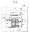
- FIG. 1is a block diagram of a field programmable gate array logic upon which the present invention may be practiced.
- FIG. 2Ashows one example of an individual cell.
- FIG. 2Bshows another example of an individual cell.
- FIG. 3Ashows a logical cluster
- FIG. 3Bshows the extension of I-matrix intraconnections of a logical cluster to a neighboring logical cluster.
- FIG. 4Ashows an example of a logical cluster with vertical block connectors.
- FIG. 4Bshows an example of a logical cluster with horizontal block connectors.
- FIG. 5Ashows the eight block connector to level 1 MLA exchange networks associated with a logical block and level 1 MLA turn points.
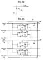
- FIG. 5Bshows a level 1 MLA turn point.
- FIG. 5Cshows an exchange network
- FIG. 6shows the routing network for a block cluster.
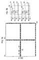
- FIG. 7Ashows the block diagram of a block sector.
- FIG. 7Bshows a level 1 to level 2 MLA routing exchange network.
- FIG. 8Ashows a sector cluster
- FIG. 8Bshows a level 2 to level 3 MLA routing exchange network.
- FIG. 1a block diagram of a field programmable gate array logic upon which the present invention may be practiced is shown as 100 .
- the I/O logical blocks 102 , 103 , 111 and 112provide an interface between external package pins of the FPGA and the internal user logic either directly or through the I/O to Core interface 104 , 105 , 113 , and 114 .
- Core 106is comprised of a number of clusters 107 which are intraconnected by I-Matrix 101 and interconnected by MLA routing network 108 .
- Control/programming logic 109is used to control all of the bits for programming the bit and word lines.
- high voltage/currentis applied to either zap or connect a fuse.
- EEPROM, Flash, or ferroelectric technologythere is an erase cycle followed by a programming cycle for programming the logic states of the memory bits.
- a separate clock/reset logic 110is used to provide clock and reset lines on a group basis.
- each of the clusters 107is comprised of a 2 ⁇ 2 hierarchy of four cells, called a logical cluster.
- FIGS. 2A and 2Bshow examples of individual cells 200 and 250 .
- Cell 200performs multiple logic functions on two input signals (A and B) and provides an output signal X.
- cell 200is comprised of an XOR gate 201 , a two-input NAND gate 202 , and a two-input NOR gate 203 . It should be noted, however, that in other embodiments, cell 200 can include various other types and/or combinations of gates.
- Cell 250is comprised of cell 200 coupled with a D flip flop cell 260 .
- the output X of cell 200can be programmed to connect directly to the data input D of the D flip flop gate 204 by activating switch 218 .
- the data input Dcan be accessed as a third input of the combined cell 250 .
- Each of the two input signals A and B and the D input of D flip-flopcan be inverted or non-inverted, depending on the states of switches 206 - 211 .
- Activating switches 206 , 208 and 210causes signals A, B and D to be driven by drivers 212 - 214 to gates 201 - 204 in a non-inverted fashion.
- Activating switches 207 , 209 , and 211causes the input signals A, B and D to be inverted by inverters 215 - 217 before being passed to gates 201 - 204 .
- the six switches 212 - 217can individually be turned on and off as programmed by the user.
- XOR gate 201NAND gate 202 , and NOR gate 203 can also be used to perform XNOR, AND and OR by propagating the output signal to the next stage, whereby the signal can be inverted as discussed above.
- Three switches 219 - 221are respectively coupled to the outputs of the three gates 201 - 203 . Again, these switches are programmable by the user. Thereby, the user can specify which of the outputs from the gates 201 - 203 is to be sent to driver 224 as the output X from cell 200 .
- the aforementioned switches 206 - 211 , 218 - 221are comprised of bi-directional, program-controlled passgates. Depending on the state of the control signal, the switches are either conducting (i.e. passes a signal on the line) or non-conducting (i.e. does not pass the signal on the line). Switches mentioned in the following sections are similarly comprised of program-controlled passgates.
- logical cluster 107is shown.
- logical cluster 107is comprised of four cells 301 - 304 and a D flip-flop 305 , twenty five switches 306 - 330 , and five intraconnections lines 331 - 335 .
- D flip flop 305 and cell 304form a cell 361 , such as cell 250 described with respect to FIG. 2 a .
- the Intraconnection lines 331 - 335 and switches 306 - 330form the I-Matrix.
- I-Matrixprovide connectability of the output, X, of each of the four cells 301 - 304 , and the output X of the D flip-flop 305 to at least one input of each of the other three cells and the D flip-flop.
- the output X of cell 301can be connected to input A of cell 302 by enabling switches 306 and 307 .
- the output X of cell 301can be connected to input B of cell 303 by enabling switches 306 and 310 .
- Output X of cell 301can be connected to input A of cell 304 by enabling switches 306 and 308 .
- Output X of cell 301can be connected to input D of the D flip-flop cell 305 by enabling switches 306 and 309 .
- the output X from cell 302can be connected to input A of cell 301 by enabling switches 311 and 312 .
- the output X from cell 302can be connected to input A of cell 303 by enabling switches 311 and 315 .
- the output X from cell 302can be connected to input B of cell 304 by enabling switches 311 and 313 .
- Output X of cell 302can be connected to input D of the D flip-flop cell 305 by enabling switches 311 and 314 .
- the output X from cell 303can be connected to input B of cell 301 by enabling switches 326 and 327 .
- the output X from cell 303can be connected to input A of cell 302 by enabling switches 326 and 328 .
- the output X from cell 303can be connected to input B of cell 304 by enabling switches 326 and 329 .
- Output X of cell 303can be connected to input D of the D flip-flop cell 305 by enabling switches 326 and 330 .
- the output X from cell 304can be connected to input B of cell 301 by enabling switches 316 and 317 .
- the output X from cell 304can be connected to input B of cell 302 by enabling switches 316 and 318 .
- the output X from cell 304can be connected to input A of cell 303 by enabling switches 316 and 319 .
- Output X of cell 304can be programmably connected to input D of the D flip-flop cell 305 by enabling switch 218 in FIG. 2 A.
- cell 305its output is connectable to the A input of cell 301 by enabling switches 320 and 321 ; the B input of cell 302 by enabling switches 320 and 322 ; the B input of cell 303 by enabling switches 320 and 325 ; the A input of cell 304 by enabling switches 320 and 323 ; and the D input of cell 305 itself by enabling switches 320 and 324 .
- each output of the cells 301 - 304 and of the D flip-flop 305is connectable to the input of each of its neighboring cells and/or flip-flop inside the cluster.
- each logical clusteris connectable to all the other logical clusters inside each logical block through passgate switches extending the I-Matrix from neighboring clusters inside each logical block.
- FIG. 3Billustrates the extension of I-Matrix intraconnection lines 331 - 335 of the cells 301 - 304 and the D flip-flop 305 of a logical cluster 107 to a neighboring logical cluster 107 through the passgate switches 336 - 355 within the same logical block.
- each logical blockis connectable to all the other logical blocks of the FPGA. This is accomplished by implementing an architecture with multiple layers of interconnections. It is important to note that this multiple layers routing architecture is a conceptual hierarchy, not a process or technology hierarchy and is hence readily implementable with today's silicon process technology.
- the bottom most layer of interconnectionsis referred to as the “block connectors”.
- a set of block connectorsprovides the access and interconnections of signals within an associated logical block (which is consisted of four logical clusters or 16 cells). Thereby, different sets of logical clusters within the same logical block are connectable to any of the other logical clusters within that group through the use of extended I-Matrix and/or block connectors.
- programmable bi-directional passgatesare used as switches to provide routing flexibility to the user.
- the next level of connectionsis referred to as the “level 1 Multiple Level Architecture (MLA)” routing network.
- the level 1 MLA routing networkprovides the interconnections between several sets of block connectors.
- Programmable passgates switchesare used to provide users with the capability of selecting which of the block connectors are to be connected. Consequently, a first logical block from one set of logical block groups is connectable to a second logical block belonging to the same group.
- the appropriate switchesare enabled to connect the block connectors of the first logical block to the routing lines of the level 1 MLA routing network.
- the appropriate switches of the level 1 MLA routing networkare enabled to provide the connections to the block connectors of the second logical block to the routing lines of the level 1 MLA routing network.
- the appropriate switchesare enabled to connect the routing lines of the level 1 MLA routing network that connected to the block connectors of the first and the second logical blocks. Furthermore, the user has the additional flexibility of programming the various switches within any given logical block to effect the desired intraconnections between each of the cells of any logical block.
- the next level of connectionsis referred to as the “level 2 Multiple Level Architecture (MLA)” routing network.
- the level 2 MLAprovides the interconnections to the various level 1 MLA to effect access and connections of a block cluster. Again, bi-directional passgate switches are programmed by the user to effect the desired connections.
- level 2 MLA routing networkBy implementing level 2 MLA routing network, programmable interconnections between even larger numbers of logical blocks is achieved.
- Additional levels of MLA routing networkscan be implemented to provide programmable interconnections for ever increasing numbers and groups of logical blocks, block clusters, block sectors, etc.
- the present inventiontakes a three dimensional approach for implementing routing. Signals are routed amongst the intraconnections of a logical block. These signals can then be accessed through block connectors and routed according to the programmed connections of the block connectors. If needed, signals are “elevated” to the level 1 MLA, routed through the level 1 MLA routing network, “de-elevated” to the appropriate block connectors, and then passed to the destination logical block.
- level 2 MLA routing networkIf level 2 MLA routing network is required, some of the signals are elevated a second time from a level 1 MLA routing network line to the level 2 MLA routing network, routed to a different set of level 2 MLA routing network line, and “de-elevated” from the level 2 MLA routing network line to a Level 1 MLA routing network line. Thereupon, the signals are “de-elevated” a second time to pass the signal from the level 1 MLA to the appropriate block connectors of the destination logical block. This same approach is performed for level 3, 4, 5, etc. MLAs on an as needed basis, depending on the size and density of the FPGA. Partial level n MLA can be implemented using the above discussed method to implement a FPGA with a given cell array count.
- FIG. 4Ashows an example of a logical cluster and the associated vertical block connectors within the logical block.
- each cell in a logical clusteris accessible from the input by two vertical block connectors and each output of the cell in a logical cluster is accessible to two of the vertical block connectors.
- input A of cell 301is accessible to the vertical block connectors 451 (BC-V 11 ) and 453 (BC-V 21 ) through switches 467 , 462 respectively
- input B of cell 301is accessible to the vertical block connectors 452 (BC-V 12 ) and 454 (BC-V 22 ) through switches 466 , 468 respectively
- output X of cell 301is accessible to the vertical block connectors 455 (BC-V 31 ) and 458 (BC-V 42 ) through switches 460 , 459 respectively.
- Input A of cell 302is accessible to the vertical block connectors 453 (BC-V 21 ) and 455 (BC-V 31 ) through switches 463 , 464 respectively
- input B of cell 302is accessible to the vertical block connectors 454 (BC-V 22 ) and 456 (BC-V 32 ) through switches 469 , 470 respectively
- output X of cell 302is accessible to the vertical block connectors 452 (BC-V 12 ) and 457 (BC-V 41 ) through switches 461 , 465 respectively.
- Input A of cell 303is accessible to the vertical block connectors 451 (BC-V 11 ) and 453 (BC-V 21 ) through switches 485 , 476 respectively
- input B of cell 303is accessible to the vertical block connectors 452 (BC-V 12 ) and 454 (BC-V 22 ) through switches 480 , 476 respectively
- output X of cell 303is accessible to the vertical block connectors 455 (BC-V 31 ) and 458 (BC-V 42 ) through switches 472 , 471 respectively.
- the input A of cell 304is accessible to the vertical block connectors 453 (BC-V 21 ) and 455 (BC-V 31 ) through switches 477 , 478 respectively
- input B of cell 304is accessible to the vertical block connectors 454 (BC-V 22 ) and 456 (BC-V 32 ) through switches 482 , 484 respectively
- output X of cell 304is accessible to the vertical block connectors 452 (BC-V 12 ) and 457 (BC-V 41 ) through switches 475 , 474 respectively.
- D flip-flop cell 305 inputis accessible to the vertical block connectors 454 (BC-V 22 ) and 455 (BC-V 31 ) through switches 473 , 479 respectively
- output X of cell 305is accessible to the vertical block connectors 452 (BC-V 12 ) and 457 (BC-V 41 ) through switches 483 , 486 respectively.
- FIG. 4Bshows the possible connections corresponding to horizontal block connectors and the logical cluster shown in FIG. 4 A.
- Input A of cell 301is accessible to the horizontal block connectors 402 (BC-H 12 ) and 404 (BC-H 22 ) through switches 409 , 413 respectively
- input B of cell 301is accessible to the horizontal block connectors 401 (BC-H 11 ) and 403 (BC-H 21 ) through switches 415 , 416 respectively
- output X of cell 301is accessible to the horizontal block connectors 405 (BC-H 31 ) and 408 (BC-H 42 ) through switches 421 , 428 respectively.
- Input A of cell 302is accessible to the horizontal block connectors 402 (BC-H 12 ) and 404 (BC-H 22 ) through switches 411 , 414 respectively
- input B of cell 302is accessible to the horizontal block connectors 401 (BC-H 11 ) and 403 (BC-H 21 ) through switches 433 , 417 respectively
- output X of cell 302is accessible to the horizontal block connectors 405 (BC-H 31 ) and 408 (BC-H 42 ) through switches 418 , 424 respectively.
- Input A of cell 303is accessible to the horizontal block connectors 404 (BC-H 22 ) and 406 (BC-H 32 ) through switches 419 , 426 respectively
- input B of cell 303is accessible to the horizontal block connectors 403 (BC-H 21 ) and 405 (BC-H 31 ) through switches 420 , 425 respectively
- output X of cell 303is accessible to the horizontal block connectors 402 (BC-H 12 ) and 407 (BC-H 41 ) through switches 410 , 427 respectively.
- the input A of cell 304is accessible to the horizontal block connectors 404 (BC-H 22 ) and 406 (BC-H 32 ) through switches 422 , 430 respectively
- input B of cell 304is accessible to the horizontal block connectors 403 (BC-H 21 ) and 405 (BC-H 31 ) through switches 423 , 429 respectively
- output X of cell 304is accessible to the horizontal block connectors 402 (BC-H 12 ) and 407 (BC-H 41 ) through switches 412 , 434 respectively.
- D flip-flop cell 305 inputis accessible to the horizontal block connectors 403 (BC-H 21 ) and 406 (BC-H 32 ) through switches 436 , 431 respectively
- output X of cell 305is accessible to the horizontal block connectors 401 (BC-H 11 ) and 408 (BC-H 42 ) through switches 432 , 435 respectively.
- FIGS. 4A and 4Billustrate the vertical and horizontal block connectors accessing method to the upper left (NW) logical cluster inside a logical block in the currently preferred embodiment.
- the lower left (SW) clusterhas the identical accessing method to the vertical block connectors as those of the NW cluster.
- the upper right (NE) clusterhas similar accessing method to those of the NW cluster with respect to the vertical block connectors except the sequence of vertical block connector access is shifted.
- the vertical block connectors 451 - 458can be viewed as chained together as a cylinder ( 451 , 452 , . . . , 458 ).
- any shift, say by 4,forms a new sequence: ( 455 , 456 , 457 , 458 , 451 , 452 , 453 , 454 ).
- the cell 301 in the NE clusteris accessible to VBCs 455 and 457 .
- the numberingis “shifted” by four.
- the access labeling of the lower right (SE) cluster to the VBCsis identical to those of NE cluster.
- the horizontal block connectors access to the NW clusteris identical to those of the NE cluster and the SW cluster is identical to the SE cluster while the horizontal block connectors access to the SW cluster is shifted by four compared with those of NW cluster.
- sixteen block connectorsare used per logical block (i.e. four clusters, or a 4 ⁇ 4 cell array).
- Adding a level 1 MLA routing networkallows for the connectability for a block cluster (an 8 ⁇ 8 cell array).
- Adding level 2 MLA routing networkincreases the connectability to a block sector (16 ⁇ 16 cell array).
- Additional levels of MLA routing networkincreases the number of block sectors by factors of four while the length (or reach) of each line in the MLA routing network increases by factors of two.
- the number of routing lines in the level 2 MLAis increased by a factor of two; since the number of block sectors increased by a factor of four, on a per unit area basis, the number of routing lines in the next level of hierarchy actually decreases by a factor of two.
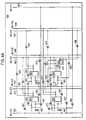
- FIG. 5Ashows a logical block with associated sixteen block connectors and level 1 MLA routing lines associated with the logical block.
- the sixteen block connectors 501 - 516are depicted by heavy lines whereas the sixteen level 1 MLA routing network lines 517 - 532 are depicted by lighter lines. Note that the length or span of the block connectors terminates within the logical block while the length of the level 1 MLA routing network lines extends to neighboring logical blocks (twice the length of the block connectors).
- Both block connectors and level 1 MLA routing network linesare subdivided into horizontal and vertical groups: vertical block connectors 501 - 508 , horizontal block connectors 509 - 516 , vertical level 1 MLA routing network lines 517 - 524 , and horizontal level 1 MLA routing network lines 525 - 532 .
- level 1 MLA turn pointsthere are twenty four level 1 MLA turn points for the sixteen level 1 MLA routing network lines within the logical block.
- the twenty four turn pointsare depicted as clear dots 541 - 564 .
- a MLA turn pointis a programmable bi-directional passgate for providing connectability between a horizontal MLA routing network line and a vertical MLA routing network line.
- enabling level 1 MLA turn point 541causes the horizontal level 1 MLA routing network line 526 and vertical level 1 MLA routing network line 520 to become connected together.
- FIG. 5Bshows level 1 MLA turn point 541 .
- Switch 583controls whether level 1 MLA routing network line 526 is to be connected to level 1 MLA routing network line 520 .
- level 1 MLA routing network line 526is connected to level 1 MLA routing network line 520 . Otherwise, line 526 is not connected to line 520 .
- Switch 583is programmable by the user. The turn points are placed as pair-wise groups with the objective of providing switching access connecting two or more block connectors first through the block connector to level 1 MLA exchange networks and then connecting selected level 1 MLA routing lines by enabling the switches. The level 1 MLA lines are used to connect those block connectors that reside in separate logical blocks within the same block cluster.
- FIG. 5Cshows the exchange network 537 in greater detail.
- the block connector to level 1 MLA routing exchange networkhas eight drivers 575 - 582 . These eight drivers 575 - 582 are used to provide bi-directional drive for the block connectors 501 , 502 and level 1 MLA lines 517 , 518 . For example, enabling switch 565 causes the signal on block connector 501 to be driven by driver 575 onto the level 1 MLA line 517 .
- Enabling switch 566causes the signal on level 1 MLA line 517 to be driven by driver 576 onto the block connector 501 .
- Enabling switch 567causes the signal on block connector 501 to be driven by driver 577 onto the level 1 MLA line 518 .
- Enabling switch 568causes the signal on level 1 MLA line 518 to be driven by driver 578 onto the block connector 501 .
- enabling switch 569causes the signal on block connector 502 to be driven by driver 579 onto the level 1 MLA line 517 .
- Enabling switch 570causes the signal on level 1 MLA line 517 to be driven by driver 580 onto the block connector 502 .
- Enabling switch 571causes the signal on block connector 502 to be driven by driver 581 onto the level 1 MLA line 518 .
- Enabling switch 572causes the signal on level 1 MLA line 518 to be driven by driver 582 onto the block connector 502 .
- Switch 573is used to control whether a signal should pass form one block connector 501 to the adjacent block connector 584 belonging to the adjacent logical block.
- switch 574is used to control whether a signal should pass form one block connector 502 to the adjacent block connector 585 belonging to the adjacent logical block.
- FIG. 6shows the routing network for a block cluster.
- the block clusteris basically comprised of four logical blocks which can be interconnected by the level 1 MLA exchange networks 533 - 540 . It can be seen that there are thirty-two level 1 MLA routing network lines.
- FIG. 7Ashows the block diagram for a block sector.
- the block sectoris comprised of four block clusters 701 - 704 .
- the block clustersare interconnected by block connectors and level 1 MLA routing network lines.
- the block sectoris also comprised of sixty-four level 2 MLA routing network lines and sixty-four level 2 to level 1 exchange networks to provide connectability between level 1 MLA routing network and level 2 MLA routing network.
- the level 1 to level 2 MLA routing exchange networksare depicted by rectangles in FIG. 7 A.
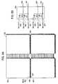
- FIG. 7Bshows a sample level 1 to level 2 MLA routing exchange network 705 .
- switch 710is used to control whether a signal should pass between level 1 MLA line 709 and level 2 MLA line 708 .
- Switch 711is used to control whether a signal should pass between level 1 MLA line 709 and level 2 MLA line 707 .
- Switch 712is used to control whether a signal should pass between level 1 MLA line 706 and level 2 MLA line 708 .
- Switch 713is used to control whether a signal should pass between level 1 MLA line 706 and level 2 MLA line 707 .
- Switch 714is used to control whether a signal should pass form one level 1 MLA line 709 to the adjacent level 1 MLA line 716 belonging to the adjacent block cluster.
- switch 715is used to control whether a signal should pass form one level 1 MLA line 706 to the adjacent level 1 MLA line 715 belonging to the adjacent block cluster.
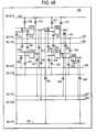
- FIG. 8Ashows a sector cluster.
- the sector clusteris comprised of four block sectors 801 - 804 with their associated block connectors, level 1, and level 2 MLA routing network lines and exchange networks.
- there are total of one hundred and twenty-eight level 3 MLA routing exchange networkfor providing programmable connectability between the various level 2 and level 3 MLA lines.
- FIG. 8Bshows an example of a level 2 to level 3 MLA routing exchange network 805 .
- enabling switch 810causes a signal on the level 2 MLA line 808 to be connected to the level 3 MLA line 806 .
- Disabling switch 810disconnects the level 2 MLA line 808 from the level 3 MLA line 806 .
- Enabling switch 811causes a signal on the level 2 MLA line 808 to be connected to the level 3 MLA line 807 .
- Disabling switch 811disconnects the level 2 MLA line 808 from the level 3 MLA line 807 .
- enabling switch 812causes a signal on the level 2 MLA line 809 to be connected to the level 3 MLA line 806 .
- Disabling switch 812disconnects the level 2 MLA line 809 from the level 3 MLA line 806 .
- Enabling switch 813causes a signal on the level 2 MLA line 809 to be connected to the level 3 MLA line 807 .
- Disabling switch 813disconnects the level 2 MLA line 809 from the level 3 MLA line 807 .
- larger and more powerful FPGAscan be achieved by adding additional logic sector clusters which are connected by additional levels of MLA routing networks with the corresponding MLA turn points and exchange networks.
- each of the five I-Matrix lines( 331 - 335 , FIG. 3A) can be extended to provide connectability between two adjacent I-Matrix lines belonging to two different clusters.
- the passgate switches 336 - 340 , 341 - 345 , 346 - 350 , and 351 - 355 in FIG. 3Bare examples of four different sets of I-Matrix line extension switches. This provides further flexibility by providing the capability of routing a signal between two adjacent clusters without having to be routed through the use of block connectors.
- block connectorscan be extended to provide connectability between two adjacent block connectors belonging to two different logical blocks.
- Switch 573 of FIG. 5Cillustrates such block connector extension connecting block connector 501 to block connector 584 through switch 573 .
- Thisprovides further flexibility by providing the capability of routing a signal between two adjacent logical blocks without having to be routed through the level 1 MLA lines and associated MLA exchange networks.
- This conceptcan be similarly applied to the level 1 MLA lines as well.
- Switch 714 of FIG. 7Bshows an example where level 1 MLA line 709 is extended to connect to level 1 MLA line 716 by enabling switch 714 .
- Thisprovides further flexibility by providing the capability of routing a signal between two adjacent block clusters without having to be routed through the level 2 MLA lines and associated MLA exchange networks.
Landscapes
- Physics & Mathematics (AREA)
- Mathematical Physics (AREA)
- Engineering & Computer Science (AREA)
- Computer Hardware Design (AREA)
- Computing Systems (AREA)
- General Engineering & Computer Science (AREA)
- Computer Networks & Wireless Communication (AREA)
- Design And Manufacture Of Integrated Circuits (AREA)
- Logic Circuits (AREA)
Abstract
Description
Claims (112)
Priority Applications (6)
| Application Number | Priority Date | Filing Date | Title |
|---|---|---|---|
| US10/269,364US6703861B2 (en) | 1993-08-03 | 2002-10-11 | Architecture and interconnect scheme for programmable logic circuits |
| US10/692,880US7017136B2 (en) | 1993-08-03 | 2003-10-23 | Architecture and interconnect scheme for programmable logic circuits |
| US11/299,248US7409664B2 (en) | 1993-08-03 | 2005-12-09 | Architecture and interconnect scheme for programmable logic circuits |
| US12/215,118US7646218B2 (en) | 1993-08-03 | 2008-06-24 | Architecture and interconnect scheme for programmable logic circuits |
| US12/630,679US20100073024A1 (en) | 1993-08-03 | 2009-12-03 | Architecture and interconnect scheme for programmable logic circuits |
| US12/943,846US8289047B2 (en) | 1993-08-03 | 2010-11-10 | Architecture and interconnect scheme for programmable logic circuits |
Applications Claiming Priority (5)
| Application Number | Priority Date | Filing Date | Title |
|---|---|---|---|
| US08/101,197US5457410A (en) | 1993-08-03 | 1993-08-03 | Architecture and interconnect scheme for programmable logic circuits |
| US48492295A | 1995-06-07 | 1995-06-07 | |
| US09/034,769US6433580B1 (en) | 1993-08-03 | 1998-03-02 | Architecture and interconnect scheme for programmable logic circuits |
| US09/955,589US6507217B2 (en) | 1993-08-03 | 2001-09-13 | Architecture and interconnect scheme for programmable logic circuits |
| US10/269,364US6703861B2 (en) | 1993-08-03 | 2002-10-11 | Architecture and interconnect scheme for programmable logic circuits |
Related Parent Applications (1)
| Application Number | Title | Priority Date | Filing Date |
|---|---|---|---|
| US09/955,589ContinuationUS6507217B2 (en) | 1993-08-03 | 2001-09-13 | Architecture and interconnect scheme for programmable logic circuits |
Related Child Applications (1)
| Application Number | Title | Priority Date | Filing Date |
|---|---|---|---|
| US10/692,880ContinuationUS7017136B2 (en) | 1993-08-03 | 2003-10-23 | Architecture and interconnect scheme for programmable logic circuits |
Publications (2)
| Publication Number | Publication Date |
|---|---|
| US20030042931A1 US20030042931A1 (en) | 2003-03-06 |
| US6703861B2true US6703861B2 (en) | 2004-03-09 |
Family
ID=22283464
Family Applications (9)
| Application Number | Title | Priority Date | Filing Date |
|---|---|---|---|
| US08/101,197Expired - Fee RelatedUS5457410A (en) | 1993-08-03 | 1993-08-03 | Architecture and interconnect scheme for programmable logic circuits |
| US09/034,769Expired - Fee RelatedUS6433580B1 (en) | 1993-08-03 | 1998-03-02 | Architecture and interconnect scheme for programmable logic circuits |
| US09/955,589Expired - Fee RelatedUS6507217B2 (en) | 1993-08-03 | 2001-09-13 | Architecture and interconnect scheme for programmable logic circuits |
| US10/269,364Expired - Fee RelatedUS6703861B2 (en) | 1993-08-03 | 2002-10-11 | Architecture and interconnect scheme for programmable logic circuits |
| US10/692,880Expired - Fee RelatedUS7017136B2 (en) | 1993-08-03 | 2003-10-23 | Architecture and interconnect scheme for programmable logic circuits |
| US11/299,248Expired - Fee RelatedUS7409664B2 (en) | 1993-08-03 | 2005-12-09 | Architecture and interconnect scheme for programmable logic circuits |
| US12/215,118Expired - Fee RelatedUS7646218B2 (en) | 1993-08-03 | 2008-06-24 | Architecture and interconnect scheme for programmable logic circuits |
| US12/630,679AbandonedUS20100073024A1 (en) | 1993-08-03 | 2009-12-03 | Architecture and interconnect scheme for programmable logic circuits |
| US12/943,846Expired - Fee RelatedUS8289047B2 (en) | 1993-08-03 | 2010-11-10 | Architecture and interconnect scheme for programmable logic circuits |
Family Applications Before (3)
| Application Number | Title | Priority Date | Filing Date |
|---|---|---|---|
| US08/101,197Expired - Fee RelatedUS5457410A (en) | 1993-08-03 | 1993-08-03 | Architecture and interconnect scheme for programmable logic circuits |
| US09/034,769Expired - Fee RelatedUS6433580B1 (en) | 1993-08-03 | 1998-03-02 | Architecture and interconnect scheme for programmable logic circuits |
| US09/955,589Expired - Fee RelatedUS6507217B2 (en) | 1993-08-03 | 2001-09-13 | Architecture and interconnect scheme for programmable logic circuits |
Family Applications After (5)
| Application Number | Title | Priority Date | Filing Date |
|---|---|---|---|
| US10/692,880Expired - Fee RelatedUS7017136B2 (en) | 1993-08-03 | 2003-10-23 | Architecture and interconnect scheme for programmable logic circuits |
| US11/299,248Expired - Fee RelatedUS7409664B2 (en) | 1993-08-03 | 2005-12-09 | Architecture and interconnect scheme for programmable logic circuits |
| US12/215,118Expired - Fee RelatedUS7646218B2 (en) | 1993-08-03 | 2008-06-24 | Architecture and interconnect scheme for programmable logic circuits |
| US12/630,679AbandonedUS20100073024A1 (en) | 1993-08-03 | 2009-12-03 | Architecture and interconnect scheme for programmable logic circuits |
| US12/943,846Expired - Fee RelatedUS8289047B2 (en) | 1993-08-03 | 2010-11-10 | Architecture and interconnect scheme for programmable logic circuits |
Country Status (10)
| Country | Link |
|---|---|
| US (9) | US5457410A (en) |
| EP (2) | EP0712548B1 (en) |
| JP (2) | JP4169164B2 (en) |
| KR (1) | KR100413881B1 (en) |
| CN (1) | CN1048127C (en) |
| AT (2) | ATE236475T1 (en) |
| AU (1) | AU7356294A (en) |
| DE (2) | DE69432416D1 (en) |
| SG (1) | SG55046A1 (en) |
| WO (1) | WO1995004404A1 (en) |
Cited By (60)
| Publication number | Priority date | Publication date | Assignee | Title |
|---|---|---|---|---|
| US20040190359A1 (en)* | 2003-03-31 | 2004-09-30 | Scheuerlein Roy E. | Apparatus and method for disturb-free programming of passive element memory cells |
| US20070075737A1 (en)* | 2004-02-14 | 2007-04-05 | Herman Schmit | Configurable Circuits, IC's, and Systems |
| US7282950B1 (en)* | 2004-11-08 | 2007-10-16 | Tabula, Inc. | Configurable IC's with logic resources with offset connections |
| US20070241771A1 (en)* | 2004-02-14 | 2007-10-18 | Herman Schmit | Configurable circuits, IC's, and systems |
| US20070245272A1 (en)* | 2004-12-01 | 2007-10-18 | Andre Rohe | Concurrent optimization of physical design and operational cycle assignment |
| US20070241778A1 (en)* | 2004-11-08 | 2007-10-18 | Herman Schmit | IC with configurable storage circuits |
| US20070241786A1 (en)* | 2004-06-30 | 2007-10-18 | Andre Rohe | Configurable Integrated Circuit with Different Connection Schemes |
| US20070241777A1 (en)* | 2004-02-14 | 2007-10-18 | Herman Schmit | Configurable Circuits, IC's and Systems |
| US20070241781A1 (en)* | 2005-03-15 | 2007-10-18 | Brad Hutchings | Variable width management for a memory of a configurable IC |
| US20070241791A1 (en)* | 2004-02-14 | 2007-10-18 | Herman Schmit | Non-Sequentially Configurable IC |
| US20070241787A1 (en)* | 2004-06-30 | 2007-10-18 | Herman Schmit | Configurable Circuits, IC's, and Systems |
| US20070244961A1 (en)* | 2004-11-08 | 2007-10-18 | Herman Schmit | Configurable IC with configurable routing resources that have asymmetric Input and/or outputs |
| US20070244960A1 (en)* | 2004-11-08 | 2007-10-18 | Herman Schmit | Configurable IC's with large carry chains |
| US20070241776A1 (en)* | 2004-06-30 | 2007-10-18 | Herman Schmit | Configurable Logic Circuits with Commutative Properties |
| US20070241789A1 (en)* | 2004-06-30 | 2007-10-18 | Andre Rohe | Configurable Integrated Circuit with Offset Connection |
| US20070257702A1 (en)* | 2005-03-15 | 2007-11-08 | Brad Hutchings | Hybrid Configurable Circuit for a Configurable IC |
| US20070257700A1 (en)* | 2005-03-15 | 2007-11-08 | Andrew Caldwell | Method and apparatus for decomposing functions in a configurable IC |
| US20070285125A1 (en)* | 2004-11-08 | 2007-12-13 | Jason Redgrave | Method and Apparatus for Accessing Stored Data in a Reconfigurable IC |
| US20080018359A1 (en)* | 2004-11-08 | 2008-01-24 | Herman Schmit | Configurable IC's With Configurable Logic Resources That Have Asymmetric Inputs And/Or Outputs |
| US20080036494A1 (en)* | 2004-11-08 | 2008-02-14 | Steven Teig | Reconfigurable ic that has sections running at different looperness |
| US20080059937A1 (en)* | 2004-06-30 | 2008-03-06 | Andre Rohe | Method and apparatus for identifying connections between configurable nodes in a configurable integrated circuit |
| US20080100339A1 (en)* | 2004-11-08 | 2008-05-01 | Herman Schmit | Configurable ic with routing circuits with offset connections |
| US20080100336A1 (en)* | 2005-03-15 | 2008-05-01 | Brad Hutchings | Hybrid Logic/Interconnect Circuit in a Configurable IC |
| US20080116931A1 (en)* | 2004-11-08 | 2008-05-22 | Herman Schmit | Embedding Memory within Tile Arrangement of a Configurable IC |
| US20080129333A1 (en)* | 2004-06-30 | 2008-06-05 | Andre Rohe | Configurable Integrated Circuit with Built-in Turns |
| US20080129335A1 (en)* | 2005-03-15 | 2008-06-05 | Brad Hutchings | Configurable IC with interconnect circuits that have select lines driven by user signals |
| US20080164906A1 (en)* | 2004-11-08 | 2008-07-10 | Jason Redgrave | Storage Elements for a Configurable IC and Method and Apparatus for Accessing Data Stored in the Storage Elements |
| US20080180131A1 (en)* | 2004-11-08 | 2008-07-31 | Steven Teig | Configurable IC with Interconnect Circuits that also Perform Storage Operations |
| US20080231314A1 (en)* | 2007-03-20 | 2008-09-25 | Steven Teig | Configurable IC Having A Routing Fabric With Storage Elements |
| US7461362B1 (en) | 2005-12-01 | 2008-12-02 | Tabula, Inc. | Replacing circuit design elements with their equivalents |
| US20080307378A1 (en)* | 2004-12-01 | 2008-12-11 | Andre Rohe | Operational Cycle Assignment in a Configurable IC |
| US7489162B1 (en) | 2005-12-01 | 2009-02-10 | Tabula, Inc. | Users registers in a reconfigurable IC |
| US7504858B1 (en) | 2006-03-08 | 2009-03-17 | Tabula, Inc. | Configurable integrated circuit with parallel non-neighboring offset connections |
| US7518400B1 (en) | 2006-03-08 | 2009-04-14 | Tabula, Inc. | Barrel shifter implemented on a configurable integrated circuit |
| US7529992B1 (en) | 2006-03-27 | 2009-05-05 | Tabula, Inc. | Configurable integrated circuit with error correcting circuitry |
| US7535252B1 (en) | 2007-03-22 | 2009-05-19 | Tabula, Inc. | Configurable ICs that conditionally transition through configuration data sets |
| US20090146689A1 (en)* | 2007-09-06 | 2009-06-11 | Trevis Chandler | Configuration Context Switcher with a Clocked Storage Element |
| US7564260B1 (en) | 2004-02-14 | 2009-07-21 | Tabula Inc. | VPA interconnect circuit |
| US7564261B2 (en) | 2004-11-08 | 2009-07-21 | Tabula Inc. | Embedding memory between tile arrangement of a configurable IC |
| US7587697B1 (en) | 2006-12-12 | 2009-09-08 | Tabula, Inc. | System and method of mapping memory blocks in a configurable integrated circuit |
| US7587698B1 (en) | 2004-12-01 | 2009-09-08 | Tabula Inc. | Operational time extension |
| US7609085B1 (en) | 2006-03-08 | 2009-10-27 | Tabula, Inc. | Configurable integrated circuit with a 4-to-1 multiplexer |
| US7656188B2 (en) | 2004-11-08 | 2010-02-02 | Tabula, Inc. | Reconfigurable IC that has sections running at different reconfiguration rates |
| US7669097B1 (en) | 2006-03-27 | 2010-02-23 | Tabula, Inc. | Configurable IC with error detection and correction circuitry |
| US7679401B1 (en) | 2005-12-01 | 2010-03-16 | Tabula, Inc. | User registers implemented with routing circuits in a configurable IC |
| US7694083B1 (en) | 2006-03-08 | 2010-04-06 | Tabula, Inc. | System and method for providing a virtual memory architecture narrower and deeper than a physical memory architecture |
| US7765249B1 (en) | 2005-11-07 | 2010-07-27 | Tabula, Inc. | Use of hybrid interconnect/logic circuits for multiplication |
| US7797497B1 (en) | 2006-03-08 | 2010-09-14 | Tabula, Inc. | System and method for providing more logical memory ports than physical memory ports |
| US7804730B2 (en) | 2005-03-15 | 2010-09-28 | Tabula, Inc. | Method and apparatus for accessing contents of memory cells |
| US7818361B1 (en) | 2005-11-07 | 2010-10-19 | Tabula, Inc. | Method and apparatus for performing two's complement multiplication |
| US7917559B2 (en) | 2004-11-08 | 2011-03-29 | Tabula, Inc. | Configurable IC's with configurable logic circuits that perform adder and/or subtractor operations |
| US7930666B1 (en) | 2006-12-12 | 2011-04-19 | Tabula, Inc. | System and method of providing a memory hierarchy |
| US7971172B1 (en) | 2005-11-07 | 2011-06-28 | Tabula, Inc. | IC that efficiently replicates a function to save logic and routing resources |
| US20110221471A1 (en)* | 2008-09-17 | 2011-09-15 | Jason Redgrave | Controllable storage elements for an ic |
| US8166435B2 (en) | 2008-06-26 | 2012-04-24 | Tabula, Inc. | Timing operations in an IC with configurable circuits |
| US8289047B2 (en) | 1993-08-03 | 2012-10-16 | Actel Corporation | Architecture and interconnect scheme for programmable logic circuits |
| US8463836B1 (en) | 2005-11-07 | 2013-06-11 | Tabula, Inc. | Performing mathematical and logical operations in multiple sub-cycles |
| US8863067B1 (en) | 2008-02-06 | 2014-10-14 | Tabula, Inc. | Sequential delay analysis by placement engines |
| US8941409B2 (en) | 2011-07-01 | 2015-01-27 | Tabula, Inc. | Configurable storage elements |
| US9148151B2 (en) | 2011-07-13 | 2015-09-29 | Altera Corporation | Configurable storage elements |
Families Citing this family (189)
| Publication number | Priority date | Publication date | Assignee | Title |
|---|---|---|---|---|
| US5367208A (en) | 1986-09-19 | 1994-11-22 | Actel Corporation | Reconfigurable programmable interconnect architecture |
| US5377124A (en)* | 1989-09-20 | 1994-12-27 | Aptix Corporation | Field programmable printed circuit board |
| GB9223226D0 (en) | 1992-11-05 | 1992-12-16 | Algotronix Ltd | Improved configurable cellular array (cal ii) |
| US5648912A (en)* | 1993-04-12 | 1997-07-15 | International Business Machines Corporation | Interconnection resource assignment method for differential current switch nets |
| GB9312674D0 (en)* | 1993-06-18 | 1993-08-04 | Pilkington Micro Electronics | Configurabel logic array |
| US6462578B2 (en) | 1993-08-03 | 2002-10-08 | Btr, Inc. | Architecture and interconnect scheme for programmable logic circuits |
| US6051991A (en)* | 1993-08-03 | 2000-04-18 | Btr, Inc. | Architecture and interconnect scheme for programmable logic circuits |
| US5682107A (en)* | 1994-04-01 | 1997-10-28 | Xilinx, Inc. | FPGA architecture with repeatable tiles including routing matrices and logic matrices |
| DE69534659T2 (en)* | 1994-04-14 | 2006-09-07 | BTR, Inc., Reno | Architecture and connection model for programmable logic circuits |
| US5424655A (en)* | 1994-05-20 | 1995-06-13 | Quicklogic Corporation | Programmable application specific integrated circuit employing antifuses and methods therefor |
| US5689686A (en)* | 1994-07-29 | 1997-11-18 | Cypress Semiconductor Corp. | Methods for maximizing routability in a programmable interconnect matrix having less than full connectability |
| US5587923A (en)* | 1994-09-07 | 1996-12-24 | Lsi Logic Corporation | Method for estimating routability and congestion in a cell placement for integrated circuit chip |
| US5537057A (en)* | 1995-02-14 | 1996-07-16 | Altera Corporation | Programmable logic array device with grouped logic regions and three types of conductors |
| US5530378A (en)* | 1995-04-26 | 1996-06-25 | Xilinx, Inc. | Cross point interconnect structure with reduced area |
| GB9508932D0 (en)* | 1995-05-02 | 1995-06-21 | Xilinx Inc | FPGA with parallel and serial user interfaces |
| US5850564A (en)* | 1995-05-03 | 1998-12-15 | Btr, Inc, | Scalable multiple level tab oriented interconnect architecture |
| WO1996035261A1 (en) | 1995-05-03 | 1996-11-07 | Btr, Inc. | Scalable multiple level interconnect architecture |
| US5745372A (en)* | 1995-05-04 | 1998-04-28 | Hewlett-Packard Company | Apparatus and method for routing signals in a field programmable gate array integrated circuit |
| US5963049A (en) | 1995-05-17 | 1999-10-05 | Altera Corporation | Programmable logic array integrated circuit architectures |
| US5614840A (en)* | 1995-05-17 | 1997-03-25 | Altera Corporation | Programmable logic array integrated circuits with segmented, selectively connectable, long interconnection conductors |
| US5541530A (en)* | 1995-05-17 | 1996-07-30 | Altera Corporation | Programmable logic array integrated circuits with blocks of logic regions grouped into super-blocks |
| US5909126A (en)* | 1995-05-17 | 1999-06-01 | Altera Corporation | Programmable logic array integrated circuit devices with interleaved logic array blocks |
| US5652529A (en)* | 1995-06-02 | 1997-07-29 | International Business Machines Corporation | Programmable array clock/reset resource |
| US5818254A (en)* | 1995-06-02 | 1998-10-06 | Advanced Micro Devices, Inc. | Multi-tiered hierarchical high speed switch matrix structure for very high-density complex programmable logic devices |
| JP3518936B2 (en)* | 1995-08-23 | 2004-04-12 | ローム株式会社 | Programmable functional devices |
| GB2305759A (en)* | 1995-09-30 | 1997-04-16 | Pilkington Micro Electronics | Semi-conductor integrated circuit |
| US5773994A (en)* | 1995-12-15 | 1998-06-30 | Cypress Semiconductor Corp. | Method and apparatus for implementing an internal tri-state bus within a programmable logic circuit |
| US6237029B1 (en) | 1996-02-26 | 2001-05-22 | Argosystems, Inc. | Method and apparatus for adaptable digital protocol processing |
| US6570404B1 (en) | 1996-03-29 | 2003-05-27 | Altera Corporation | High-performance programmable logic architecture |
| US5835998A (en)* | 1996-04-04 | 1998-11-10 | Altera Corporation | Logic cell for programmable logic devices |
| US5847969A (en)* | 1996-05-01 | 1998-12-08 | Hewlett-Packard Co. | Integrated circuit design system and method for generating a regular structure embedded in a standard cell control block |
| US5894565A (en)* | 1996-05-20 | 1999-04-13 | Atmel Corporation | Field programmable gate array with distributed RAM and increased cell utilization |
| US5742181A (en)* | 1996-06-04 | 1998-04-21 | Hewlett-Packard Co. | FPGA with hierarchical interconnect structure and hyperlinks |
| GB9614800D0 (en)* | 1996-07-13 | 1996-09-04 | Plessey Semiconductors Ltd | Programmable logic arrays |
| US6094066A (en)* | 1996-08-03 | 2000-07-25 | Mission Research Corporation | Tiered routing architecture for field programmable gate arrays |
| US6034547A (en)* | 1996-09-04 | 2000-03-07 | Advantage Logic, Inc. | Method and apparatus for universal program controlled bus |
| US6624658B2 (en)* | 1999-02-04 | 2003-09-23 | Advantage Logic, Inc. | Method and apparatus for universal program controlled bus architecture |
| US5781032A (en)* | 1996-09-09 | 1998-07-14 | International Business Machines Corporation | Programmable inverter circuit used in a programmable logic cell |
| US5880597A (en)* | 1996-09-18 | 1999-03-09 | Altera Corporation | Interleaved interconnect for programmable logic array devices |
| US5977793A (en)* | 1996-10-10 | 1999-11-02 | Altera Corporation | Programmable logic device with hierarchical interconnection resources |
| US6300794B1 (en) | 1996-10-10 | 2001-10-09 | Altera Corporation | Programmable logic device with hierarchical interconnection resources |
| US5999016A (en)* | 1996-10-10 | 1999-12-07 | Altera Corporation | Architectures for programmable logic devices |
| US6286093B1 (en)* | 1996-12-10 | 2001-09-04 | Logic Express Systems, Inc. | Multi-bus programmable interconnect architecture |
| US5898317A (en)* | 1996-12-23 | 1999-04-27 | Motorola, Inc. | Configurable monolithic semiconductor circuit and method for configuring |
| US5959466A (en) | 1997-01-31 | 1999-09-28 | Actel Corporation | Field programmable gate array with mask programmed input and output buffers |
| US5936426A (en) | 1997-02-03 | 1999-08-10 | Actel Corporation | Logic function module for field programmable array |
| US6127844A (en)* | 1997-02-20 | 2000-10-03 | Altera Corporation | PCI-compatible programmable logic devices |
| US5982195A (en)* | 1997-02-20 | 1999-11-09 | Altera Corporation | Programmable logic device architectures |
| US5999015A (en)* | 1997-02-20 | 1999-12-07 | Altera Corporation | Logic region resources for programmable logic devices |
| US7148722B1 (en) | 1997-02-20 | 2006-12-12 | Altera Corporation | PCI-compatible programmable logic devices |
| US5963050A (en)* | 1997-02-26 | 1999-10-05 | Xilinx, Inc. | Configurable logic element with fast feedback paths |
| US5920202A (en)* | 1997-02-26 | 1999-07-06 | Xilinx, Inc. | Configurable logic element with ability to evaluate five and six input functions |
| US5889411A (en)* | 1997-02-26 | 1999-03-30 | Xilinx, Inc. | FPGA having logic element carry chains capable of generating wide XOR functions |
| US6201410B1 (en) | 1997-02-26 | 2001-03-13 | Xilinx, Inc. | Wide logic gate implemented in an FPGA configurable logic element |
| US6204689B1 (en) | 1997-02-26 | 2001-03-20 | Xilinx, Inc. | Input/output interconnect circuit for FPGAs |
| US5942913A (en)* | 1997-03-20 | 1999-08-24 | Xilinx, Inc. | FPGA repeatable interconnect structure with bidirectional and unidirectional interconnect lines |
| US5914616A (en)* | 1997-02-26 | 1999-06-22 | Xilinx, Inc. | FPGA repeatable interconnect structure with hierarchical interconnect lines |
| US6150837A (en)* | 1997-02-28 | 2000-11-21 | Actel Corporation | Enhanced field programmable gate array |
| US6184710B1 (en) | 1997-03-20 | 2001-02-06 | Altera Corporation | Programmable logic array devices with enhanced interconnectivity between adjacent logic regions |
| US6130551A (en)* | 1998-01-19 | 2000-10-10 | Vantis Corporation | Synthesis-friendly FPGA architecture with variable length and variable timing interconnect |
| US6121790A (en)* | 1997-10-16 | 2000-09-19 | Altera Corporation | Programmable logic device with enhanced multiplexing capabilities in interconnect resources |
| US6107825A (en)* | 1997-10-16 | 2000-08-22 | Altera Corporation | Input/output circuitry for programmable logic devices |
| US6084427A (en) | 1998-05-19 | 2000-07-04 | Altera Corporation | Programmable logic devices with enhanced multiplexing capabilities |
| US6107824A (en)* | 1997-10-16 | 2000-08-22 | Altera Corporation | Circuitry and methods for internal interconnection of programmable logic devices |
| US6289494B1 (en) | 1997-11-12 | 2001-09-11 | Quickturn Design Systems, Inc. | Optimized emulation and prototyping architecture |
| US6069490A (en)* | 1997-12-02 | 2000-05-30 | Xilinx, Inc. | Routing architecture using a direct connect routing mesh |
| US6185724B1 (en) | 1997-12-02 | 2001-02-06 | Xilinx, Inc. | Template-based simulated annealing move-set that improves FPGA architectural feature utilization |
| US6104207A (en)* | 1998-04-27 | 2000-08-15 | Lattice Semiconductor Corporation | Programmable logic device |
| US7389487B1 (en) | 1998-04-28 | 2008-06-17 | Actel Corporation | Dedicated interface architecture for a hybrid integrated circuit |
| US6092174A (en)* | 1998-06-01 | 2000-07-18 | Context, Inc. | Dynamically reconfigurable distributed integrated circuit processor and method |
| US6243664B1 (en) | 1998-10-27 | 2001-06-05 | Cypress Semiconductor Corporation | Methods for maximizing routability in a programmable interconnect matrix having less than full connectability |
| US6507216B1 (en) | 1998-11-18 | 2003-01-14 | Altera Corporation | Efficient arrangement of interconnection resources on programmable logic devices |
| US6215326B1 (en) | 1998-11-18 | 2001-04-10 | Altera Corporation | Programmable logic device architecture with super-regions having logic regions and a memory region |
| US6407576B1 (en) | 1999-03-04 | 2002-06-18 | Altera Corporation | Interconnection and input/output resources for programmable logic integrated circuit devices |
| US7185293B1 (en)* | 1999-11-29 | 2007-02-27 | Cellot, Inc. | Universal hardware device and method and tools for use therewith |
| US6320412B1 (en) | 1999-12-20 | 2001-11-20 | Btr, Inc. C/O Corporate Trust Co. | Architecture and interconnect for programmable logic circuits |
| US7251249B2 (en)* | 2000-01-26 | 2007-07-31 | Tundra Semiconductor Corporation | Integrated high speed switch router using a multiport architecture |
| US8149048B1 (en) | 2000-10-26 | 2012-04-03 | Cypress Semiconductor Corporation | Apparatus and method for programmable power management in a programmable analog circuit block |
| US6724220B1 (en) | 2000-10-26 | 2004-04-20 | Cyress Semiconductor Corporation | Programmable microcontroller architecture (mixed analog/digital) |
| US8160864B1 (en) | 2000-10-26 | 2012-04-17 | Cypress Semiconductor Corporation | In-circuit emulator and pod synchronized boot |
| US8176296B2 (en) | 2000-10-26 | 2012-05-08 | Cypress Semiconductor Corporation | Programmable microcontroller architecture |
| US7765095B1 (en) | 2000-10-26 | 2010-07-27 | Cypress Semiconductor Corporation | Conditional branching in an in-circuit emulation system |
| US8103496B1 (en) | 2000-10-26 | 2012-01-24 | Cypress Semicondutor Corporation | Breakpoint control in an in-circuit emulation system |
| GB2374242B (en)* | 2001-04-07 | 2005-03-16 | Univ Dundee | Integrated circuit and related improvements |
| US6605962B2 (en)* | 2001-05-06 | 2003-08-12 | Altera Corporation | PLD architecture for flexible placement of IP function blocks |
| US7076595B1 (en)* | 2001-05-18 | 2006-07-11 | Xilinx, Inc. | Programmable logic device including programmable interface core and central processing unit |
| US20030020082A1 (en)* | 2001-07-25 | 2003-01-30 | Motorola, Inc. | Structure and method for fabricating semiconductor structures and devices for optical switching |
| DE10139610A1 (en)* | 2001-08-11 | 2003-03-06 | Daimler Chrysler Ag | Universal computer architecture |
| US6781407B2 (en) | 2002-01-09 | 2004-08-24 | Xilinx, Inc. | FPGA and embedded circuitry initialization and processing |
| US7420392B2 (en)* | 2001-09-28 | 2008-09-02 | Xilinx, Inc. | Programmable gate array and embedded circuitry initialization and processing |
| US6798239B2 (en)* | 2001-09-28 | 2004-09-28 | Xilinx, Inc. | Programmable gate array having interconnecting logic to support embedded fixed logic circuitry |
| US6594810B1 (en) | 2001-10-04 | 2003-07-15 | M2000 | Reconfigurable integrated circuit with a scalable architecture |
| US7406674B1 (en) | 2001-10-24 | 2008-07-29 | Cypress Semiconductor Corporation | Method and apparatus for generating microcontroller configuration information |
| US8078970B1 (en) | 2001-11-09 | 2011-12-13 | Cypress Semiconductor Corporation | Graphical user interface with user-selectable list-box |
| US8042093B1 (en) | 2001-11-15 | 2011-10-18 | Cypress Semiconductor Corporation | System providing automatic source code generation for personalization and parameterization of user modules |
| US6996758B1 (en) | 2001-11-16 | 2006-02-07 | Xilinx, Inc. | Apparatus for testing an interconnecting logic fabric |
| US6983405B1 (en) | 2001-11-16 | 2006-01-03 | Xilinx, Inc., | Method and apparatus for testing circuitry embedded within a field programmable gate array |
| US7774190B1 (en) | 2001-11-19 | 2010-08-10 | Cypress Semiconductor Corporation | Sleep and stall in an in-circuit emulation system |
| US8069405B1 (en) | 2001-11-19 | 2011-11-29 | Cypress Semiconductor Corporation | User interface for efficiently browsing an electronic document using data-driven tabs |
| US7844437B1 (en) | 2001-11-19 | 2010-11-30 | Cypress Semiconductor Corporation | System and method for performing next placements and pruning of disallowed placements for programming an integrated circuit |
| US6886092B1 (en)* | 2001-11-19 | 2005-04-26 | Xilinx, Inc. | Custom code processing in PGA by providing instructions from fixed logic processor portion to programmable dedicated processor portion |
| US6971004B1 (en) | 2001-11-19 | 2005-11-29 | Cypress Semiconductor Corp. | System and method of dynamically reconfiguring a programmable integrated circuit |
| US7770113B1 (en) | 2001-11-19 | 2010-08-03 | Cypress Semiconductor Corporation | System and method for dynamically generating a configuration datasheet |
| US6820248B1 (en) | 2002-02-14 | 2004-11-16 | Xilinx, Inc. | Method and apparatus for routing interconnects to devices with dissimilar pitches |
| US6754882B1 (en) | 2002-02-22 | 2004-06-22 | Xilinx, Inc. | Method and system for creating a customized support package for an FPGA-based system-on-chip (SoC) |
| US6976160B1 (en) | 2002-02-22 | 2005-12-13 | Xilinx, Inc. | Method and system for controlling default values of flip-flops in PGA/ASIC-based designs |
| US6934922B1 (en) | 2002-02-27 | 2005-08-23 | Xilinx, Inc. | Timing performance analysis |
| US7007121B1 (en) | 2002-02-27 | 2006-02-28 | Xilinx, Inc. | Method and apparatus for synchronized buses |
| US6839874B1 (en) | 2002-02-28 | 2005-01-04 | Xilinx, Inc. | Method and apparatus for testing an embedded device |
| US7111217B1 (en) | 2002-02-28 | 2006-09-19 | Xilinx, Inc. | Method and system for flexibly nesting JTAG TAP controllers for FPGA-based system-on-chip (SoC) |
| US7111220B1 (en) | 2002-03-01 | 2006-09-19 | Xilinx, Inc. | Network physical layer with embedded multi-standard CRC generator |
| US7088767B1 (en) | 2002-03-01 | 2006-08-08 | Xilinx, Inc. | Method and apparatus for operating a transceiver in different data rates |
| US7187709B1 (en) | 2002-03-01 | 2007-03-06 | Xilinx, Inc. | High speed configurable transceiver architecture |
| US6961919B1 (en)* | 2002-03-04 | 2005-11-01 | Xilinx, Inc. | Method of designing integrated circuit having both configurable and fixed logic circuitry |
| US8103497B1 (en) | 2002-03-28 | 2012-01-24 | Cypress Semiconductor Corporation | External interface for event architecture |
| US6577159B1 (en) | 2002-04-22 | 2003-06-10 | Nicholas Jesse Macias | Method and apparatus for automatic high-speed bypass routing in a cell matrix self-configurable hardware system |
| US7308608B1 (en) | 2002-05-01 | 2007-12-11 | Cypress Semiconductor Corporation | Reconfigurable testing system and method |
| JP2003338750A (en)* | 2002-05-20 | 2003-11-28 | Nec Electronics Corp | General-purpose logic cell, general-purose logic cell array using same, and asic using the general-purpose logic cell array |
| US6973405B1 (en) | 2002-05-22 | 2005-12-06 | Xilinx, Inc. | Programmable interactive verification agent |
| US6772405B1 (en) | 2002-06-13 | 2004-08-03 | Xilinx, Inc. | Insertable block tile for interconnecting to a device embedded in an integrated circuit |
| US7112994B2 (en)* | 2002-07-08 | 2006-09-26 | Viciciv Technology | Three dimensional integrated circuits |
| US6992503B2 (en) | 2002-07-08 | 2006-01-31 | Viciciv Technology | Programmable devices with convertibility to customizable devices |
| US7085973B1 (en) | 2002-07-09 | 2006-08-01 | Xilinx, Inc. | Testing address lines of a memory controller |
| EP1543414A2 (en)* | 2002-08-29 | 2005-06-22 | BAE SYSTEMS Information and Electronic Systems Integration, Inc. | Mechanism for integrating programmable devices into software based frameworks for distributed computing |
| US20040045007A1 (en)* | 2002-08-30 | 2004-03-04 | Bae Systems Information Electronic Systems Integration, Inc. | Object oriented component and framework architecture for signal processing |
| US7099426B1 (en) | 2002-09-03 | 2006-08-29 | Xilinx, Inc. | Flexible channel bonding and clock correction operations on a multi-block data path |
| US7761845B1 (en) | 2002-09-09 | 2010-07-20 | Cypress Semiconductor Corporation | Method for parameterizing a user module |
| US7092865B1 (en) | 2002-09-10 | 2006-08-15 | Xilinx, Inc. | Method and apparatus for timing modeling |
| US8643162B2 (en) | 2007-11-19 | 2014-02-04 | Raminda Udaya Madurawe | Pads and pin-outs in three dimensional integrated circuits |
| US7255437B2 (en)* | 2003-10-09 | 2007-08-14 | Howell Thomas A | Eyeglasses with activity monitoring |
| US7421014B2 (en)* | 2003-09-11 | 2008-09-02 | Xilinx, Inc. | Channel bonding of a plurality of multi-gigabit transceivers |
| US7030651B2 (en) | 2003-12-04 | 2006-04-18 | Viciciv Technology | Programmable structured arrays |
| US7126373B1 (en) | 2004-02-14 | 2006-10-24 | Herman Schmit | Configurable logic circuits with commutative properties |
| US7622951B2 (en) | 2004-02-14 | 2009-11-24 | Tabula, Inc. | Via programmable gate array with offset direct connections |
| US7193432B1 (en) | 2004-02-14 | 2007-03-20 | Herman Schmit | VPA logic circuits |
| US7157933B1 (en) | 2004-02-14 | 2007-01-02 | Herman Schmit | Configurable circuits, IC's, and systems |
| US7295049B1 (en) | 2004-03-25 | 2007-11-13 | Cypress Semiconductor Corporation | Method and circuit for rapid alignment of signals |
| US6975139B2 (en)* | 2004-03-30 | 2005-12-13 | Advantage Logic, Inc. | Scalable non-blocking switching network for programmable logic |
| US7449915B2 (en)* | 2004-06-30 | 2008-11-11 | Tabula Inc. | VPA logic circuits |
| US7460529B2 (en) | 2004-07-29 | 2008-12-02 | Advantage Logic, Inc. | Interconnection fabric using switching networks in hierarchy |
| US8069436B2 (en) | 2004-08-13 | 2011-11-29 | Cypress Semiconductor Corporation | Providing hardware independence to automate code generation of processing device firmware |
| US8286125B2 (en) | 2004-08-13 | 2012-10-09 | Cypress Semiconductor Corporation | Model for a hardware device-independent method of defining embedded firmware for programmable systems |
| US20060080632A1 (en)* | 2004-09-30 | 2006-04-13 | Mathstar, Inc. | Integrated circuit layout having rectilinear structure of objects |
| US20070244958A1 (en)* | 2004-11-08 | 2007-10-18 | Jason Redgrave | Configurable IC's with carry bypass circuitry |
| US20070247189A1 (en)* | 2005-01-25 | 2007-10-25 | Mathstar | Field programmable semiconductor object array integrated circuit |
| US7332976B1 (en) | 2005-02-04 | 2008-02-19 | Cypress Semiconductor Corporation | Poly-phase frequency synthesis oscillator |
| US20070244959A1 (en)* | 2005-03-15 | 2007-10-18 | Steven Teig | Configurable IC's with dual carry chains |
| EP1713007B1 (en)* | 2005-04-11 | 2008-09-17 | STMicroelectronics S.r.l. | A dynamically reconfigurable System-on-Chip comprising a plurality of reconfigurable gate array devices |
| US7304497B2 (en)* | 2005-04-29 | 2007-12-04 | Altera Corporation | Methods and apparatus for programmably powering down structured application-specific integrated circuits |
| US7400183B1 (en) | 2005-05-05 | 2008-07-15 | Cypress Semiconductor Corporation | Voltage controlled oscillator delay cell and method |
| US8089461B2 (en) | 2005-06-23 | 2012-01-03 | Cypress Semiconductor Corporation | Touch wake for electronic devices |
| US7478261B2 (en)* | 2005-09-13 | 2009-01-13 | M2000 | Reconfigurable circuit with redundant reconfigurable cluster(s) |
| US8010826B2 (en)* | 2005-09-13 | 2011-08-30 | Meta Systems | Reconfigurable circuit with redundant reconfigurable cluster(s) |
| US7262633B1 (en) | 2005-11-11 | 2007-08-28 | Tabula, Inc. | Via programmable gate array with offset bit lines |
| US7275196B2 (en) | 2005-11-23 | 2007-09-25 | M2000 S.A. | Runtime reconfiguration of reconfigurable circuits |
| US8085067B1 (en) | 2005-12-21 | 2011-12-27 | Cypress Semiconductor Corporation | Differential-to-single ended signal converter circuit and method |
| US7423453B1 (en) | 2006-01-20 | 2008-09-09 | Advantage Logic, Inc. | Efficient integrated circuit layout scheme to implement a scalable switching network used in interconnection fabric |
| US8067948B2 (en) | 2006-03-27 | 2011-11-29 | Cypress Semiconductor Corporation | Input/output multiplexer bus |
| US7576563B1 (en)* | 2007-02-06 | 2009-08-18 | Lattice Semiconductor Corporation | High fan-out signal routing systems and methods |
| US7737724B2 (en) | 2007-04-17 | 2010-06-15 | Cypress Semiconductor Corporation | Universal digital block interconnection and channel routing |
| US8040266B2 (en) | 2007-04-17 | 2011-10-18 | Cypress Semiconductor Corporation | Programmable sigma-delta analog-to-digital converter |
| US8026739B2 (en) | 2007-04-17 | 2011-09-27 | Cypress Semiconductor Corporation | System level interconnect with programmable switching |
| US8092083B2 (en) | 2007-04-17 | 2012-01-10 | Cypress Semiconductor Corporation | Temperature sensor with digital bandgap |
| US8516025B2 (en) | 2007-04-17 | 2013-08-20 | Cypress Semiconductor Corporation | Clock driven dynamic datapath chaining |
| US8130025B2 (en) | 2007-04-17 | 2012-03-06 | Cypress Semiconductor Corporation | Numerical band gap |
| US9564902B2 (en) | 2007-04-17 | 2017-02-07 | Cypress Semiconductor Corporation | Dynamically configurable and re-configurable data path |
| US9720805B1 (en) | 2007-04-25 | 2017-08-01 | Cypress Semiconductor Corporation | System and method for controlling a target device |
| US8266575B1 (en) | 2007-04-25 | 2012-09-11 | Cypress Semiconductor Corporation | Systems and methods for dynamically reconfiguring a programmable system on a chip |
| US8065653B1 (en) | 2007-04-25 | 2011-11-22 | Cypress Semiconductor Corporation | Configuration of programmable IC design elements |
| US8049569B1 (en) | 2007-09-05 | 2011-11-01 | Cypress Semiconductor Corporation | Circuit and method for improving the accuracy of a crystal-less oscillator having dual-frequency modes |
| US8468712B2 (en) | 2007-11-13 | 2013-06-25 | E.I. Du Pont De Nemours And Company | Method for bonding a transparent substrate to a liquid crystal display and associated device |
| US20090144595A1 (en)* | 2007-11-30 | 2009-06-04 | Mathstar, Inc. | Built-in self-testing (bist) of field programmable object arrays |
| US8098080B2 (en)* | 2008-02-29 | 2012-01-17 | Renesas Electronics Corporation | Semiconductor programmable device |
| US8230375B2 (en) | 2008-09-14 | 2012-07-24 | Raminda Udaya Madurawe | Automated metal pattern generation for integrated circuits |
| US7705629B1 (en)* | 2008-12-03 | 2010-04-27 | Advantage Logic, Inc. | Permutable switching network with enhanced interconnectivity for multicasting signals |
| US7714611B1 (en) | 2008-12-03 | 2010-05-11 | Advantage Logic, Inc. | Permutable switching network with enhanced multicasting signals routing for interconnection fabric |
| US9448964B2 (en) | 2009-05-04 | 2016-09-20 | Cypress Semiconductor Corporation | Autonomous control in a programmable system |
| US7999570B2 (en)* | 2009-06-24 | 2011-08-16 | Advantage Logic, Inc. | Enhanced permutable switching network with multicasting signals for interconnection fabric |
| US9323994B2 (en) | 2009-12-15 | 2016-04-26 | Micron Technology, Inc. | Multi-level hierarchical routing matrices for pattern-recognition processors |
| US8269524B2 (en)* | 2010-04-27 | 2012-09-18 | Atmel Corporation | General purpose input/output pin mapping |
| FR2964522A1 (en)* | 2010-09-07 | 2012-03-09 | Sagemcom Energy & Telecom Sas | ROLLING DEVICE, INTEGRATED CIRCUIT COMPRISING SUCH A ROTATING DEVICE, AND COMMUNICATION NODE DEVICE COMPRISING SUCH A CALLING DEVICE |
| KR101802945B1 (en)* | 2011-06-27 | 2017-12-29 | 삼성전자주식회사 | Logic device and semiconductor package having the same |
| US9847783B1 (en) | 2015-10-13 | 2017-12-19 | Altera Corporation | Scalable architecture for IP block integration |
| CN108427829B (en)* | 2018-02-09 | 2022-11-08 | 京微齐力(北京)科技有限公司 | FPGA with common line structure |
| US10855284B1 (en)* | 2018-09-25 | 2020-12-01 | Flex Logix Technologies, Inc. | Process of routing tile-to-tile interconnects of an FPGA, and method of manufacturing an FPGA |
| US10803225B2 (en)* | 2019-01-24 | 2020-10-13 | Efinix, Inc. | Peripheral tool |
| US10587270B2 (en) | 2019-06-12 | 2020-03-10 | Intel Corporation | Coarse-grain programmable routing network for logic devices |
| US10749528B2 (en) | 2019-08-20 | 2020-08-18 | Intel Corporation | Stacked programmable integrated circuitry with smart memory |
| US12119819B1 (en) | 2021-12-13 | 2024-10-15 | Flex Logix Technologies, Inc. | Power-up switch-interconnect configuration |
Citations (32)
| Publication number | Priority date | Publication date | Assignee | Title |
|---|---|---|---|---|
| US4020469A (en) | 1975-04-09 | 1977-04-26 | Frank Manning | Programmable arrays |
| GB2180382A (en) | 1985-09-11 | 1987-03-25 | Pilkington Micro Electronics | Semiconductor integrated circuits/systems |
| US4661901A (en) | 1982-12-23 | 1987-04-28 | International Business Machines Corporation | Microprocessor control system utilizing overlapped programmable logic arrays |
| US4700187A (en) | 1985-12-02 | 1987-10-13 | Concurrent Logic, Inc. | Programmable, asynchronous logic cell and array |
| US4720780A (en) | 1985-09-17 | 1988-01-19 | The Johns Hopkins University | Memory-linked wavefront array processor |
| US4736333A (en) | 1983-08-15 | 1988-04-05 | California Institute Of Technology | Electronic musical instrument |
| US4758745A (en) | 1986-09-19 | 1988-07-19 | Actel Corporation | User programmable integrated circuit interconnect architecture and test method |
| US4847612A (en) | 1988-01-13 | 1989-07-11 | Plug Logic, Inc. | Programmable logic device |
| US4870302A (en) | 1984-03-12 | 1989-09-26 | Xilinx, Inc. | Configurable electrical circuit having configurable logic elements and configurable interconnects |
| US4912342A (en) | 1988-05-05 | 1990-03-27 | Altera Corporation | Programmable logic device with array blocks with programmable clocking |
| US4918440A (en) | 1986-11-07 | 1990-04-17 | Furtek Frederick C | Programmable logic cell and array |
| US4992680A (en) | 1988-12-28 | 1991-02-12 | Sgs-Thomson Microelectronics S.R.L. | Programmable logic device having a plurality of programmable logic arrays arranged in a mosaic layout together with a plurality of interminglingly arranged interfacing blocks |
| EP0415542A2 (en) | 1989-08-15 | 1991-03-06 | Advanced Micro Devices, Inc. | Programmable gate array with improved interconnect structure, input/output structure and configurable logic block |
| WO1992008286A1 (en) | 1990-11-02 | 1992-05-14 | Concurrent Logic, Inc. | Programmable logic cell and array |
| US5122685A (en) | 1991-03-06 | 1992-06-16 | Quicklogic Corporation | Programmable application specific integrated circuit and logic cell therefor |
| US5204556A (en) | 1991-05-06 | 1993-04-20 | Lattice Semiconductor Corporation | Programmable interconnect structure for logic blocks |
| US5208491A (en) | 1992-01-07 | 1993-05-04 | Washington Research Foundation | Field programmable gate array |
| US5221865A (en) | 1991-06-21 | 1993-06-22 | Crosspoint Solutions, Inc. | Programmable input/output buffer circuit with test capability |
| USRE34363E (en) | 1984-03-12 | 1993-08-31 | Xilinx, Inc. | Configurable electrical circuit having configurable logic elements and configurable interconnects |
| US5243238A (en) | 1989-03-17 | 1993-09-07 | Algotronix Limited | Configurable cellular array |
| US5260610A (en) | 1991-09-03 | 1993-11-09 | Altera Corporation | Programmable logic element interconnections for programmable logic array integrated circuits |
| US5296759A (en) | 1991-08-29 | 1994-03-22 | National Semiconductor Corporation | Diagonal wiring between abutting logic cells in a configurable logic array |
| US5298805A (en) | 1991-08-29 | 1994-03-29 | National Semiconductor Corporation | Versatile and efficient cell-to-local bus interface in a configurable logic array |
| WO1994010754A1 (en) | 1992-11-05 | 1994-05-11 | Xilinx, Inc. | Improved configurable cellular array |
| US5329470A (en) | 1988-12-02 | 1994-07-12 | Quickturn Systems, Inc. | Reconfigurable hardware emulation system |
| US5396126A (en) | 1993-02-19 | 1995-03-07 | At&T Corp. | FPGA with distributed switch matrix |
| US5457410A (en) | 1993-08-03 | 1995-10-10 | Btr, Inc. | Architecture and interconnect scheme for programmable logic circuits |
| US5477067A (en) | 1987-05-27 | 1995-12-19 | Hitachi, Ltd. | Semiconductor IC device having a RAM interposed between different logic sections and by-pass signal lines extending over the RAM for mutually connecting the logic sections |
| US5519629A (en) | 1993-07-19 | 1996-05-21 | Hewlett-Packard Company | Tileable gate array cell for programmable logic devices and gate array having tiled gate array cells |
| US5550782A (en) | 1991-09-03 | 1996-08-27 | Altera Corporation | Programmable logic array integrated circuits |
| US5581767A (en) | 1993-06-16 | 1996-12-03 | Nippon Sheet Glass Co., Ltd. | Bus structure for multiprocessor system having separated processor section and control/memory section |
| US6160420A (en) | 1986-09-19 | 2000-12-12 | Actel Corporation | Programmable interconnect architecture |
Family Cites Families (65)
| Publication number | Priority date | Publication date | Assignee | Title |
|---|---|---|---|---|
| US3473160A (en)* | 1966-10-10 | 1969-10-14 | Stanford Research Inst | Electronically controlled microelectronic cellular logic array |
| US4207556A (en)* | 1976-12-14 | 1980-06-10 | Nippon Telegraph And Telephone Public Corporation | Programmable logic array arrangement |
| US4642487A (en)* | 1984-09-26 | 1987-02-10 | Xilinx, Inc. | Special interconnect for configurable logic array |
| US4706216A (en)* | 1985-02-27 | 1987-11-10 | Xilinx, Inc. | Configurable logic element |
| US4763020B1 (en)* | 1985-09-06 | 1997-07-08 | Ricoh Kk | Programmable logic device having plural programmable function cells |
| US5187393A (en) | 1986-09-19 | 1993-02-16 | Actel Corporation | Reconfigurable programmable interconnect architecture |
| US4786904A (en)* | 1986-12-15 | 1988-11-22 | Zoran Corporation | Electronically programmable gate array having programmable interconnect lines |
| US4815003A (en) | 1987-06-19 | 1989-03-21 | General Electric Company | Structured design method for high density standard cell and macrocell layout of VLSI chips |
| US4855619A (en)* | 1987-11-17 | 1989-08-08 | Xilinx, Inc. | Buffered routing element for a user programmable logic device |
| EP0317287B1 (en)* | 1987-11-20 | 1992-11-11 | Kawasaki Steel Corporation | Programmable logic device |
| US5225221A (en)* | 1987-12-28 | 1993-07-06 | The Procter & Gamble Company | Preparation of calcium-supplemented beverages by dispersing calcium hydroxide in pasteurized juice stream |
| JPH01274512A (en)* | 1988-04-27 | 1989-11-02 | Hitachi Ltd | Semiconductor logic device |
| US5012135A (en)* | 1989-05-12 | 1991-04-30 | Plus Logic, Inc. | Logic gates with a programmable number of inputs |
| US4967107A (en)* | 1989-05-12 | 1990-10-30 | Plus Logic, Inc. | Programmable logic expander |
| US5343406A (en)* | 1989-07-28 | 1994-08-30 | Xilinx, Inc. | Distributed memory architecture for a configurable logic array and method for using distributed memory |
| US5185706A (en)* | 1989-08-15 | 1993-02-09 | Advanced Micro Devices, Inc. | Programmable gate array with logic cells having configurable output enable |
| US5231588A (en)* | 1989-08-15 | 1993-07-27 | Advanced Micro Devices, Inc. | Programmable gate array with logic cells having symmetrical input/output structures |
| JPH03139863A (en)* | 1989-10-25 | 1991-06-14 | Hitachi Ltd | semiconductor integrated circuit |
| US5140193A (en)* | 1990-03-27 | 1992-08-18 | Xilinx, Inc. | Programmable connector for programmable logic device |
| US5349691A (en) | 1990-07-03 | 1994-09-20 | Xilinx, Inc. | Programming process for 3-level programming logic devices |
| US5224056A (en)* | 1991-10-30 | 1993-06-29 | Xilinx, Inc. | Logic placement using positionally asymmetrical partitioning algorithm |
| JP2564044B2 (en) | 1991-02-27 | 1996-12-18 | 株式会社東芝 | Programmable logic circuit |
| US5220213A (en)* | 1991-03-06 | 1993-06-15 | Quicklogic Corporation | Programmable application specific integrated circuit and logic cell therefor |
| US5327023A (en)* | 1991-03-28 | 1994-07-05 | Kawasaki Steel Corporation | Programmable logic device |
| US5436575A (en)* | 1991-09-03 | 1995-07-25 | Altera Corporation | Programmable logic array integrated circuits |
| US5371422A (en)* | 1991-09-03 | 1994-12-06 | Altera Corporation | Programmable logic device having multiplexers and demultiplexers randomly connected to global conductors for interconnections between logic elements |
| US5260611A (en)* | 1991-09-03 | 1993-11-09 | Altera Corporation | Programmable logic array having local and long distance conductors |
| US5422833A (en)* | 1991-10-30 | 1995-06-06 | Xilinx, Inc. | Method and system for propagating data type for circuit design from a high level block diagram |
| US5291079A (en)* | 1992-07-23 | 1994-03-01 | Xilinx, Inc. | Configuration control unit for programming a field programmable gate array and reading array status |
| US5331226A (en)* | 1992-07-23 | 1994-07-19 | Xilinx, Inc. | Logic cell for field programmable gate array having optional input inverters |
| JP3139863B2 (en) | 1993-01-29 | 2001-03-05 | ヤンマーディーゼル株式会社 | Marine propulsion device |
| US5483178A (en)* | 1993-03-29 | 1996-01-09 | Altera Corporation | Programmable logic device with logic block outputs coupled to adjacent logic block output multiplexers |
| SG46393A1 (en) | 1993-05-28 | 1998-02-20 | Univ California | Field programmable logic device with dynamic interconnections to a dynamic logic core |
| GB9312674D0 (en)* | 1993-06-18 | 1993-08-04 | Pilkington Micro Electronics | Configurabel logic array |
| US5444394A (en) | 1993-07-08 | 1995-08-22 | Altera Corporation | PLD with selective inputs from local and global conductors |
| US6051991A (en) | 1993-08-03 | 2000-04-18 | Btr, Inc. | Architecture and interconnect scheme for programmable logic circuits |
| US6462578B2 (en) | 1993-08-03 | 2002-10-08 | Btr, Inc. | Architecture and interconnect scheme for programmable logic circuits |
| US5455525A (en) | 1993-12-06 | 1995-10-03 | Intelligent Logic Systems, Inc. | Hierarchically-structured programmable logic array and system for interconnecting logic elements in the logic array |
| EP0734573B1 (en) | 1993-12-13 | 2002-04-03 | Lattice Semiconductor Corporation | Application specific modules in a programmable logic device |
| US5386354A (en)* | 1993-12-17 | 1995-01-31 | Regent Lighting Corporation | Adjustable beam security light |
| US5369314A (en) | 1994-02-22 | 1994-11-29 | Altera Corporation | Programmable logic device with redundant circuitry |
| DE69534659T2 (en) | 1994-04-14 | 2006-09-07 | BTR, Inc., Reno | Architecture and connection model for programmable logic circuits |
| US5406525A (en) | 1994-06-06 | 1995-04-11 | Motorola, Inc. | Configurable SRAM and method for providing the same |
| US5656121A (en) | 1994-08-19 | 1997-08-12 | Minnesota Mining And Manufacturing Company | Method of making multi-layer composites having a fluoropolymer layer |
| US5597319A (en) | 1994-11-29 | 1997-01-28 | Methode Electronics, Inc. | Zero insertion force pin grid array socket |
| WO1996013902A1 (en) | 1994-11-01 | 1996-05-09 | Virtual Machine Works, Inc. | Programmable multiplexing input/output port |
| US5581199A (en) | 1995-01-04 | 1996-12-03 | Xilinx, Inc. | Interconnect architecture for field programmable gate array using variable length conductors |
| US5537057A (en) | 1995-02-14 | 1996-07-16 | Altera Corporation | Programmable logic array device with grouped logic regions and three types of conductors |
| US5572148A (en) | 1995-03-22 | 1996-11-05 | Altera Corporation | Programmable logic array integrated circuit with general-purpose memory configurable as a random access or FIFO memory |
| US5850564A (en) | 1995-05-03 | 1998-12-15 | Btr, Inc, | Scalable multiple level tab oriented interconnect architecture |
| WO1996035261A1 (en) | 1995-05-03 | 1996-11-07 | Btr, Inc. | Scalable multiple level interconnect architecture |
| US5656950A (en) | 1995-10-26 | 1997-08-12 | Xilinx, Inc. | Interconnect lines including tri-directional buffer circuits |
| US6034547A (en) | 1996-09-04 | 2000-03-07 | Advantage Logic, Inc. | Method and apparatus for universal program controlled bus |
| US5880597A (en) | 1996-09-18 | 1999-03-09 | Altera Corporation | Interleaved interconnect for programmable logic array devices |
| US6016063A (en) | 1998-02-04 | 2000-01-18 | Xilinx, Inc. | Method and apparatus for connecting long lines to form wide logic functions |
| US6038627A (en) | 1998-03-16 | 2000-03-14 | Actel Corporation | SRAM bus architecture and interconnect to an FPGA |
| US6064225A (en) | 1998-03-20 | 2000-05-16 | Lucent Technologies Inc. | Global signal distribution with reduced routing tracks in an FPGA |
| JP3391374B2 (en) | 1998-12-25 | 2003-03-31 | 富士通株式会社 | Crosspoint switch circuit and basic switch cell electronics |
| US6686768B2 (en) | 2001-07-05 | 2004-02-03 | Alan Elbert Comer | Electrically-programmable interconnect architecture for easily-configurable stacked circuit arrangements |
| US6975139B2 (en) | 2004-03-30 | 2005-12-13 | Advantage Logic, Inc. | Scalable non-blocking switching network for programmable logic |
| US7132852B2 (en) | 2004-04-14 | 2006-11-07 | Altera Corporation | Routing architecture with high speed I/O bypass path |
| US6998872B1 (en) | 2004-06-02 | 2006-02-14 | Xilinx, Inc. | Lookup table circuit optionally configurable as two or more smaller lookup tables with independent inputs |
| US7292065B2 (en)* | 2004-08-03 | 2007-11-06 | Altera Corporation | Enhanced passgate structures for reducing leakage current |
| US7307452B2 (en)* | 2004-10-27 | 2007-12-11 | Stmicroelectronics Pvt. Ltd. | Interconnect structure enabling indirect routing in programmable logic |
| US7212030B1 (en)* | 2004-12-31 | 2007-05-01 | Actel Corporation | Field programmable gate array long line routing network |
- 1993
- 1993-08-03USUS08/101,197patent/US5457410A/ennot_activeExpired - Fee Related
- 1994
- 1994-06-24WOPCT/US1994/007187patent/WO1995004404A1/enactiveIP Right Grant
- 1994-06-24DEDE69432416Tpatent/DE69432416D1/ennot_activeExpired - Lifetime
- 1994-06-24KRKR1019960700569Apatent/KR100413881B1/ennot_activeExpired - Fee Related
- 1994-06-24CNCN94192983Apatent/CN1048127C/ennot_activeExpired - Fee Related
- 1994-06-24JPJP50582195Apatent/JP4169164B2/ennot_activeExpired - Fee Related
- 1994-06-24ATAT94922455Tpatent/ATE236475T1/ennot_activeIP Right Cessation
- 1994-06-24SGSG1996003530Apatent/SG55046A1/enunknown
- 1994-06-24ATAT97111287Tpatent/ATE227902T1/ennot_activeIP Right Cessation
- 1994-06-24EPEP94922455Apatent/EP0712548B1/ennot_activeExpired - Lifetime
- 1994-06-24AUAU73562/94Apatent/AU7356294A/ennot_activeAbandoned
- 1994-06-24EPEP97111287Apatent/EP0806836B1/ennot_activeExpired - Lifetime
- 1994-06-24DEDE69431732Tpatent/DE69431732T2/ennot_activeExpired - Lifetime
- 1998
- 1998-03-02USUS09/034,769patent/US6433580B1/ennot_activeExpired - Fee Related
- 2001
- 2001-09-13USUS09/955,589patent/US6507217B2/ennot_activeExpired - Fee Related
- 2002
- 2002-10-11USUS10/269,364patent/US6703861B2/ennot_activeExpired - Fee Related
- 2003
- 2003-10-23USUS10/692,880patent/US7017136B2/ennot_activeExpired - Fee Related
- 2005
- 2005-12-09USUS11/299,248patent/US7409664B2/ennot_activeExpired - Fee Related
- 2008
- 2008-05-16JPJP2008129490Apatent/JP2008278508A/enactivePending
- 2008-06-24USUS12/215,118patent/US7646218B2/ennot_activeExpired - Fee Related
- 2009
- 2009-12-03USUS12/630,679patent/US20100073024A1/ennot_activeAbandoned
- 2010
- 2010-11-10USUS12/943,846patent/US8289047B2/ennot_activeExpired - Fee Related
Patent Citations (36)
| Publication number | Priority date | Publication date | Assignee | Title |
|---|---|---|---|---|
| US4020469A (en) | 1975-04-09 | 1977-04-26 | Frank Manning | Programmable arrays |
| US4661901A (en) | 1982-12-23 | 1987-04-28 | International Business Machines Corporation | Microprocessor control system utilizing overlapped programmable logic arrays |
| US4736333A (en) | 1983-08-15 | 1988-04-05 | California Institute Of Technology | Electronic musical instrument |
| US4870302A (en) | 1984-03-12 | 1989-09-26 | Xilinx, Inc. | Configurable electrical circuit having configurable logic elements and configurable interconnects |
| USRE34363E (en) | 1984-03-12 | 1993-08-31 | Xilinx, Inc. | Configurable electrical circuit having configurable logic elements and configurable interconnects |
| GB2180382A (en) | 1985-09-11 | 1987-03-25 | Pilkington Micro Electronics | Semiconductor integrated circuits/systems |
| US4935734A (en) | 1985-09-11 | 1990-06-19 | Pilkington Micro-Electronics Limited | Semi-conductor integrated circuits/systems |
| US4720780A (en) | 1985-09-17 | 1988-01-19 | The Johns Hopkins University | Memory-linked wavefront array processor |
| US4700187A (en) | 1985-12-02 | 1987-10-13 | Concurrent Logic, Inc. | Programmable, asynchronous logic cell and array |
| US4758745A (en) | 1986-09-19 | 1988-07-19 | Actel Corporation | User programmable integrated circuit interconnect architecture and test method |
| US6160420A (en) | 1986-09-19 | 2000-12-12 | Actel Corporation | Programmable interconnect architecture |
| US4758745B1 (en) | 1986-09-19 | 1994-11-15 | Actel Corp | User programmable integrated circuit interconnect architecture and test method |
| US4918440A (en) | 1986-11-07 | 1990-04-17 | Furtek Frederick C | Programmable logic cell and array |
| US5477067A (en) | 1987-05-27 | 1995-12-19 | Hitachi, Ltd. | Semiconductor IC device having a RAM interposed between different logic sections and by-pass signal lines extending over the RAM for mutually connecting the logic sections |
| US4847612A (en) | 1988-01-13 | 1989-07-11 | Plug Logic, Inc. | Programmable logic device |
| US4912342A (en) | 1988-05-05 | 1990-03-27 | Altera Corporation | Programmable logic device with array blocks with programmable clocking |
| US5329470A (en) | 1988-12-02 | 1994-07-12 | Quickturn Systems, Inc. | Reconfigurable hardware emulation system |
| US4992680A (en) | 1988-12-28 | 1991-02-12 | Sgs-Thomson Microelectronics S.R.L. | Programmable logic device having a plurality of programmable logic arrays arranged in a mosaic layout together with a plurality of interminglingly arranged interfacing blocks |
| US5243238A (en) | 1989-03-17 | 1993-09-07 | Algotronix Limited | Configurable cellular array |
| EP0415542A2 (en) | 1989-08-15 | 1991-03-06 | Advanced Micro Devices, Inc. | Programmable gate array with improved interconnect structure, input/output structure and configurable logic block |
| WO1992008286A1 (en) | 1990-11-02 | 1992-05-14 | Concurrent Logic, Inc. | Programmable logic cell and array |
| US5144166A (en) | 1990-11-02 | 1992-09-01 | Concurrent Logic, Inc. | Programmable logic cell and array |
| US5122685A (en) | 1991-03-06 | 1992-06-16 | Quicklogic Corporation | Programmable application specific integrated circuit and logic cell therefor |
| US5204556A (en) | 1991-05-06 | 1993-04-20 | Lattice Semiconductor Corporation | Programmable interconnect structure for logic blocks |
| US5221865A (en) | 1991-06-21 | 1993-06-22 | Crosspoint Solutions, Inc. | Programmable input/output buffer circuit with test capability |
| US5296759A (en) | 1991-08-29 | 1994-03-22 | National Semiconductor Corporation | Diagonal wiring between abutting logic cells in a configurable logic array |
| US5298805A (en) | 1991-08-29 | 1994-03-29 | National Semiconductor Corporation | Versatile and efficient cell-to-local bus interface in a configurable logic array |
| US5260610A (en) | 1991-09-03 | 1993-11-09 | Altera Corporation | Programmable logic element interconnections for programmable logic array integrated circuits |
| US5550782A (en) | 1991-09-03 | 1996-08-27 | Altera Corporation | Programmable logic array integrated circuits |
| US5208491A (en) | 1992-01-07 | 1993-05-04 | Washington Research Foundation | Field programmable gate array |
| US5469003A (en) | 1992-11-05 | 1995-11-21 | Xilinx, Inc. | Hierarchically connectable configurable cellular array |
| WO1994010754A1 (en) | 1992-11-05 | 1994-05-11 | Xilinx, Inc. | Improved configurable cellular array |
| US5396126A (en) | 1993-02-19 | 1995-03-07 | At&T Corp. | FPGA with distributed switch matrix |
| US5581767A (en) | 1993-06-16 | 1996-12-03 | Nippon Sheet Glass Co., Ltd. | Bus structure for multiprocessor system having separated processor section and control/memory section |
| US5519629A (en) | 1993-07-19 | 1996-05-21 | Hewlett-Packard Company | Tileable gate array cell for programmable logic devices and gate array having tiled gate array cells |
| US5457410A (en) | 1993-08-03 | 1995-10-10 | Btr, Inc. | Architecture and interconnect scheme for programmable logic circuits |
Non-Patent Citations (15)
| Title |
|---|
| Altera Corporation Date Sheet, Flex EPF81188 12,000 Gate Programmable Logic Device, Sep. 1992, Ver. 1, pp. 1-20. |
| ATMEL Field Programmable Arrays, AT 6000 Series, 1993, p. 1-16. |
| Britton, et al., "Optimized Reconfigurable Cell Array Architecture for High-Performance Field Programmable Gate Arrays," Proceedings of the IEEE 1993 Custom Integrated Circuits Conference, 1993, pp. 7.2.1.-7.2.5. |
| Buffoli, E., et al., "Dynamically Reconfigurable Devices Used to Implement a Self-Tuning, High Performances PID Controller," 1989 IEEE, pp., 107-112. |
| Cliff, et al., "A Dual Granularity and Globally Interconnected Architecture for a Programmable Logic Device", IEEE '93 pp. 7.3.1-7.3.5. |
| Devades, S., et al., "Boolean Decomposition of Programmable Logic Arrays," IEEE 1988, pp. 2.5.1-2.5.5. |
| Liu, D.L., et al., "Design of Large Embedded CMOS PLA's for Built-In Self-test," IEEE Transactions on Computed-Aided Design, vol. 7, No. 1, Jan. 1988, pp. 50-53. |
| Minnick, R.C., "A Survey of Microcellular Research", vol. 14, No. 2, Apr. 1967, pp. 203-241. |
| Shoup, R. G., "Programmable Cellular Logic Arrays," Abstract, Ph.D. Dissertation, Carnegie Mellon University, Pittsburgh, PA, Mar. 1970, (partial) pp. ii-121. |
| Spandorfer, L.M., "Synthesis of Logic Functions on an Array of Integrated Circuits," Contract No. AF 19 (628) 2907, Project No. 4645, Task No. 464504, Final Report, Nov. 30, 1965. |
| Sun, Y., et al., "An Area Minimizer for Floorplans with L-Shaped Regions," 1992 International Conference on Computer Design, 1992 IEEE, pp. 383-386. |
| Vidal, J.J., "Implementing Neural Nets with Programmable Logic," IEEE Transactions on Acoustic, Speech, and Signal Processing, vol. 36, No. 7, Jul. 1988, pp. 1180-1190. |
| Wescon '93, pp. 310-320. |
| Wescon '93, pp. 321-326. |
| Xilinx, "The Programmable Gate Array Data Book", 1992. |
Cited By (156)
| Publication number | Priority date | Publication date | Assignee | Title |
|---|---|---|---|---|
| US8289047B2 (en) | 1993-08-03 | 2012-10-16 | Actel Corporation | Architecture and interconnect scheme for programmable logic circuits |
| US6822903B2 (en)* | 2003-03-31 | 2004-11-23 | Matrix Semiconductor, Inc. | Apparatus and method for disturb-free programming of passive element memory cells |
| US20050073898A1 (en)* | 2003-03-31 | 2005-04-07 | Scheuerlein Roy E. | Apparatus and method for disturb-free programming of passive element memory cells |
| US20050101088A1 (en)* | 2003-03-31 | 2005-05-12 | Scheuerlein Roy E. | Manufacturing method for integrated circuit having disturb-free programming of passive element memory cells |
| US7022572B2 (en) | 2003-03-31 | 2006-04-04 | Matrix Semiconductor, Inc. | Manufacturing method for integrated circuit having disturb-free programming of passive element memory cells |
| US20040190359A1 (en)* | 2003-03-31 | 2004-09-30 | Scheuerlein Roy E. | Apparatus and method for disturb-free programming of passive element memory cells |
| US20090160481A9 (en)* | 2004-02-14 | 2009-06-25 | Herman Schmit | Configurable Circuits, IC's and Systems |
| US20100219859A1 (en)* | 2004-02-14 | 2010-09-02 | Herman Schmit | Non-Sequentially Configurable IC |
| US7564260B1 (en) | 2004-02-14 | 2009-07-21 | Tabula Inc. | VPA interconnect circuit |
| US20090167354A9 (en)* | 2004-02-14 | 2009-07-02 | Herman Schmit | Non-Sequentially Configurable IC |
| US7667486B2 (en) | 2004-02-14 | 2010-02-23 | Tabula, Inc. | Non-sequentially configurable IC |
| US20070241777A1 (en)* | 2004-02-14 | 2007-10-18 | Herman Schmit | Configurable Circuits, IC's and Systems |
| US7532032B2 (en) | 2004-02-14 | 2009-05-12 | Tabula, Inc. | Configurable circuits, IC's, and systems |
| US20070241771A1 (en)* | 2004-02-14 | 2007-10-18 | Herman Schmit | Configurable circuits, IC's, and systems |
| US20070241791A1 (en)* | 2004-02-14 | 2007-10-18 | Herman Schmit | Non-Sequentially Configurable IC |
| US7872496B2 (en) | 2004-02-14 | 2011-01-18 | Tabula, Inc. | Method of mapping a user design defined for a user design cycle to an IC with multiple sub-cycle reconfigurable circuits |
| US7948266B2 (en) | 2004-02-14 | 2011-05-24 | Tabula, Inc. | Non-sequentially configurable IC |
| US20070075737A1 (en)* | 2004-02-14 | 2007-04-05 | Herman Schmit | Configurable Circuits, IC's, and Systems |
| US8193830B2 (en) | 2004-02-14 | 2012-06-05 | Tabula, Inc. | Configurable circuits, IC's, and systems |
| US7616027B2 (en) | 2004-02-14 | 2009-11-10 | Tabula, Inc. | Configurable circuits, IC's and systems |
| US7425841B2 (en) | 2004-02-14 | 2008-09-16 | Tabula Inc. | Configurable circuits, IC's, and systems |
| US8305110B2 (en) | 2004-02-14 | 2012-11-06 | Tabula, Inc. | Non-sequentially configurable IC |
| US20070241789A1 (en)* | 2004-06-30 | 2007-10-18 | Andre Rohe | Configurable Integrated Circuit with Offset Connection |
| US20110163781A1 (en)* | 2004-06-30 | 2011-07-07 | Andre Rohe | Method and apparatus for identifying connections between configurable nodes in a configurable integrated circuit |
| US8645890B2 (en) | 2004-06-30 | 2014-02-04 | Tabula, Inc. | Method and apparatus for identifying connections between configurable nodes in a configurable integrated circuit |
| US20080059937A1 (en)* | 2004-06-30 | 2008-03-06 | Andre Rohe | Method and apparatus for identifying connections between configurable nodes in a configurable integrated circuit |
| US20080061823A1 (en)* | 2004-06-30 | 2008-03-13 | Herman Schmit | Configurable ic's with logic resources with offset connections |
| US7557609B2 (en) | 2004-06-30 | 2009-07-07 | Tabula, Inc. | Configurable integrated circuit with different connection schemes |
| US20070241786A1 (en)* | 2004-06-30 | 2007-10-18 | Andre Rohe | Configurable Integrated Circuit with Different Connection Schemes |
| US7737722B2 (en) | 2004-06-30 | 2010-06-15 | Tabula, Inc. | Configurable integrated circuit with built-in turns |
| US20080129333A1 (en)* | 2004-06-30 | 2008-06-05 | Andre Rohe | Configurable Integrated Circuit with Built-in Turns |
| US8281273B2 (en) | 2004-06-30 | 2012-10-02 | Tabula, Inc. | Method and apparatus for identifying connections between configurable nodes in a configurable integrated circuit |
| US20100210077A1 (en)* | 2004-06-30 | 2010-08-19 | Andre Rohe | Configurable integrated circuit with built-in turns |
| US8415973B2 (en) | 2004-06-30 | 2013-04-09 | Tabula, Inc. | Configurable integrated circuit with built-in turns |
| US7839166B2 (en) | 2004-06-30 | 2010-11-23 | Tabula, Inc. | Configurable IC with logic resources with offset connections |
| US7408382B2 (en) | 2004-06-30 | 2008-08-05 | Tabula, Inc. | Configurable circuits, IC's, and systems |
| US7849434B2 (en) | 2004-06-30 | 2010-12-07 | Tabula, Inc. | Method and apparatus for identifying connections between configurable nodes in a configurable integrated circuit |
| US8350591B2 (en) | 2004-06-30 | 2013-01-08 | Tabula, Inc. | Configurable IC's with dual carry chains |
| US20070241776A1 (en)* | 2004-06-30 | 2007-10-18 | Herman Schmit | Configurable Logic Circuits with Commutative Properties |
| US20070241787A1 (en)* | 2004-06-30 | 2007-10-18 | Herman Schmit | Configurable Circuits, IC's, and Systems |
| US7468614B2 (en) | 2004-06-30 | 2008-12-23 | Tabula, Inc. | Configurable integrated circuit with offset connections |
| US7439766B2 (en) | 2004-06-30 | 2008-10-21 | Tabula, Inc. | Configurable logic circuits with commutative properties |
| US20110202586A1 (en)* | 2004-06-30 | 2011-08-18 | Steven Teig | Configurable ic's with dual carry chains |
| US7994817B2 (en) | 2004-06-30 | 2011-08-09 | Tabula, Inc. | Configurable integrated circuit with built-in turns |
| US7917559B2 (en) | 2004-11-08 | 2011-03-29 | Tabula, Inc. | Configurable IC's with configurable logic circuits that perform adder and/or subtractor operations |
| US20070241785A1 (en)* | 2004-11-08 | 2007-10-18 | Herman Schmit | Configurable ic's with logic resources with offset connections |
| US20070244960A1 (en)* | 2004-11-08 | 2007-10-18 | Herman Schmit | Configurable IC's with large carry chains |
| US20070244961A1 (en)* | 2004-11-08 | 2007-10-18 | Herman Schmit | Configurable IC with configurable routing resources that have asymmetric Input and/or outputs |
| US20110115523A1 (en)* | 2004-11-08 | 2011-05-19 | Jason Redgrave | Storage elements for a configurable ic and method and apparatus for accessing data stored in the storage elements |
| US20080018359A1 (en)* | 2004-11-08 | 2008-01-24 | Herman Schmit | Configurable IC's With Configurable Logic Resources That Have Asymmetric Inputs And/Or Outputs |
| US20110031998A1 (en)* | 2004-11-08 | 2011-02-10 | Jason Redgrave | Configurable ic's with large carry chains |
| US7518402B2 (en) | 2004-11-08 | 2009-04-14 | Tabula, Inc. | Configurable IC with configuration logic resources that have asymmetric inputs and/or outputs |
| US8183882B2 (en) | 2004-11-08 | 2012-05-22 | Tabula, Inc. | Reconfigurable IC that has sections running at different reconfiguration rates |
| US7420389B2 (en) | 2004-11-08 | 2008-09-02 | Tabula, Inc. | Clock distribution in a configurable IC |
| US20080180131A1 (en)* | 2004-11-08 | 2008-07-31 | Steven Teig | Configurable IC with Interconnect Circuits that also Perform Storage Operations |
| US7525342B2 (en) | 2004-11-08 | 2009-04-28 | Tabula, Inc. | Reconfigurable IC that has sections running at different looperness |
| US7825687B2 (en) | 2004-11-08 | 2010-11-02 | Tabula, Inc. | Storage elements for a configurable IC and method and apparatus for accessing data stored in the storage elements |
| US20080164906A1 (en)* | 2004-11-08 | 2008-07-10 | Jason Redgrave | Storage Elements for a Configurable IC and Method and Apparatus for Accessing Data Stored in the Storage Elements |
| US8248102B2 (en) | 2004-11-08 | 2012-08-21 | Tabula, Inc. | Configurable IC'S with large carry chains |
| US8159264B2 (en) | 2004-11-08 | 2012-04-17 | Tabula, Inc. | Storage elements for a configurable IC and method and apparatus for accessing data stored in the storage elements |
| US7532030B2 (en) | 2004-11-08 | 2009-05-12 | Tabula, Inc. | Method and apparatus for accessing stored data in a reconfigurable IC |
| US7743085B2 (en) | 2004-11-08 | 2010-06-22 | Tabula, Inc. | Configurable IC with large carry chains |
| US7545167B2 (en) | 2004-11-08 | 2009-06-09 | Tabula, Inc. | Configurable IC with interconnect circuits that also perform storage operations |
| US20080116931A1 (en)* | 2004-11-08 | 2008-05-22 | Herman Schmit | Embedding Memory within Tile Arrangement of a Configurable IC |
| US20070285125A1 (en)* | 2004-11-08 | 2007-12-13 | Jason Redgrave | Method and Apparatus for Accessing Stored Data in a Reconfigurable IC |
| US20070241778A1 (en)* | 2004-11-08 | 2007-10-18 | Herman Schmit | IC with configurable storage circuits |
| US20080100339A1 (en)* | 2004-11-08 | 2008-05-01 | Herman Schmit | Configurable ic with routing circuits with offset connections |
| US20080036494A1 (en)* | 2004-11-08 | 2008-02-14 | Steven Teig | Reconfigurable ic that has sections running at different looperness |
| US7564261B2 (en) | 2004-11-08 | 2009-07-21 | Tabula Inc. | Embedding memory between tile arrangement of a configurable IC |
| US7570077B2 (en) | 2004-11-08 | 2009-08-04 | Tabula Inc. | Storage elements for a configurable IC and method and apparatus for accessing data stored in the storage elements |
| US7573296B2 (en) | 2004-11-08 | 2009-08-11 | Tabula Inc. | Configurable IC with configurable routing resources that have asymmetric input and/or outputs |
| US7576564B2 (en) | 2004-11-08 | 2009-08-18 | Tabula Inc. | Configurable IC with routing circuits with offset connections |
| US7282950B1 (en)* | 2004-11-08 | 2007-10-16 | Tabula, Inc. | Configurable IC's with logic resources with offset connections |
| US7656188B2 (en) | 2004-11-08 | 2010-02-02 | Tabula, Inc. | Reconfigurable IC that has sections running at different reconfiguration rates |
| US7652499B2 (en) | 2004-11-08 | 2010-01-26 | Tabula, Inc. | Embedding memory within tile arrangement of an integrated circuit |
| US20100007376A1 (en)* | 2004-11-08 | 2010-01-14 | Jason Redgrave | Storage elements for a configurable ic and method and apparatus for accessing data stored in the storage elements |
| US20110145776A1 (en)* | 2004-12-01 | 2011-06-16 | Andre Rohe | Operational cycle assignment in a configurable ic |
| US7870529B2 (en) | 2004-12-01 | 2011-01-11 | Tabula, Inc. | Operational cycle assignment in a configurable IC |
| US7870530B2 (en) | 2004-12-01 | 2011-01-11 | Tabula, Inc. | Operational cycle assignment in a configurable IC |
| US8683410B2 (en) | 2004-12-01 | 2014-03-25 | Tabula, Inc. | Operational cycle assignment in a configurable IC |
| US7587698B1 (en) | 2004-12-01 | 2009-09-08 | Tabula Inc. | Operational time extension |
| US8664974B2 (en) | 2004-12-01 | 2014-03-04 | Tabula, Inc. | Operational time extension |
| US20070245272A1 (en)* | 2004-12-01 | 2007-10-18 | Andre Rohe | Concurrent optimization of physical design and operational cycle assignment |
| US7898291B2 (en) | 2004-12-01 | 2011-03-01 | Tabula, Inc. | Operational time extension |
| US7496879B2 (en) | 2004-12-01 | 2009-02-24 | Tabula, Inc. | Concurrent optimization of physical design and operational cycle assignment |
| US7694265B2 (en) | 2004-12-01 | 2010-04-06 | Tabula, Inc. | Operational cycle assignment in a configurable IC |
| US20080307380A1 (en)* | 2004-12-01 | 2008-12-11 | Andre Rohe | Operational Cycle Assignment in a Configurable IC |
| US20110181317A1 (en)* | 2004-12-01 | 2011-07-28 | Andre Rohe | Operational time extension |
| US20080307378A1 (en)* | 2004-12-01 | 2008-12-11 | Andre Rohe | Operational Cycle Assignment in a Configurable IC |
| US20080129335A1 (en)* | 2005-03-15 | 2008-06-05 | Brad Hutchings | Configurable IC with interconnect circuits that have select lines driven by user signals |
| US20070257702A1 (en)* | 2005-03-15 | 2007-11-08 | Brad Hutchings | Hybrid Configurable Circuit for a Configurable IC |
| US7528627B2 (en) | 2005-03-15 | 2009-05-05 | Tabula, Inc. | Method and apparatus for performing shifting in an integrated circuit |
| US20080100336A1 (en)* | 2005-03-15 | 2008-05-01 | Brad Hutchings | Hybrid Logic/Interconnect Circuit in a Configurable IC |
| US20070257700A1 (en)* | 2005-03-15 | 2007-11-08 | Andrew Caldwell | Method and apparatus for decomposing functions in a configurable IC |
| US7804730B2 (en) | 2005-03-15 | 2010-09-28 | Tabula, Inc. | Method and apparatus for accessing contents of memory cells |
| US7816944B2 (en) | 2005-03-15 | 2010-10-19 | Tabula, Inc. | Variable width writing to a memory of an IC |
| US20080129337A1 (en)* | 2005-03-15 | 2008-06-05 | Jason Redgrave | Method and apparatus for performing shifting in an integrated circuit |
| US7932742B2 (en) | 2005-03-15 | 2011-04-26 | Tabula, Inc. | Configurable IC with interconnect circuits that have select lines driven by user signals |
| US7825684B2 (en) | 2005-03-15 | 2010-11-02 | Tabula, Inc. | Variable width management for a memory of a configurable IC |
| US7530033B2 (en) | 2005-03-15 | 2009-05-05 | Tabula, Inc. | Method and apparatus for decomposing functions in a configurable IC |
| US20070241781A1 (en)* | 2005-03-15 | 2007-10-18 | Brad Hutchings | Variable width management for a memory of a configurable IC |
| US7521958B2 (en) | 2005-03-15 | 2009-04-21 | Tabula, Inc. | Hybrid configurable circuit for a configurable IC |
| US8726213B2 (en) | 2005-03-15 | 2014-05-13 | Tabula, Inc. | Method and apparatus for decomposing functions in a configurable IC |
| US7818361B1 (en) | 2005-11-07 | 2010-10-19 | Tabula, Inc. | Method and apparatus for performing two's complement multiplication |
| US7765249B1 (en) | 2005-11-07 | 2010-07-27 | Tabula, Inc. | Use of hybrid interconnect/logic circuits for multiplication |
| US7971172B1 (en) | 2005-11-07 | 2011-06-28 | Tabula, Inc. | IC that efficiently replicates a function to save logic and routing resources |
| US8463836B1 (en) | 2005-11-07 | 2013-06-11 | Tabula, Inc. | Performing mathematical and logical operations in multiple sub-cycles |
| US9018977B2 (en) | 2005-12-01 | 2015-04-28 | Tabula, Inc. | User registers implemented with routing circuits in a configurable IC |
| US8089300B2 (en) | 2005-12-01 | 2012-01-03 | Tabula, Inc. | Users registers implemented with routing circuits in a configurable IC |
| US7461362B1 (en) | 2005-12-01 | 2008-12-02 | Tabula, Inc. | Replacing circuit design elements with their equivalents |
| US20100213977A1 (en)* | 2005-12-01 | 2010-08-26 | Jason Redgrave | Users registers implemented with routing circuits in a configurable ic |
| US7679401B1 (en) | 2005-12-01 | 2010-03-16 | Tabula, Inc. | User registers implemented with routing circuits in a configurable IC |
| US7489162B1 (en) | 2005-12-01 | 2009-02-10 | Tabula, Inc. | Users registers in a reconfigurable IC |
| US20110004734A1 (en)* | 2006-03-08 | 2011-01-06 | Herman Schmit | System and method for providing more logical memory ports than physical memory ports |
| US7504858B1 (en) | 2006-03-08 | 2009-03-17 | Tabula, Inc. | Configurable integrated circuit with parallel non-neighboring offset connections |
| US7962705B2 (en) | 2006-03-08 | 2011-06-14 | Tabula, Inc. | System and method for providing a virtual memory architecture narrower and deeper than a physical memory architecture |
| US7694083B1 (en) | 2006-03-08 | 2010-04-06 | Tabula, Inc. | System and method for providing a virtual memory architecture narrower and deeper than a physical memory architecture |
| US8230182B2 (en) | 2006-03-08 | 2012-07-24 | Tabula, Inc. | System and method for providing more logical memory ports than physical memory ports |
| US20100241800A1 (en)* | 2006-03-08 | 2010-09-23 | Herman Schmit | System and method for providing a virtual memory architecture narrower and deeper than a physical memory architecture |
| US7797497B1 (en) | 2006-03-08 | 2010-09-14 | Tabula, Inc. | System and method for providing more logical memory ports than physical memory ports |
| US7609085B1 (en) | 2006-03-08 | 2009-10-27 | Tabula, Inc. | Configurable integrated circuit with a 4-to-1 multiplexer |
| US7518400B1 (en) | 2006-03-08 | 2009-04-14 | Tabula, Inc. | Barrel shifter implemented on a configurable integrated circuit |
| US7669097B1 (en) | 2006-03-27 | 2010-02-23 | Tabula, Inc. | Configurable IC with error detection and correction circuitry |
| US7529992B1 (en) | 2006-03-27 | 2009-05-05 | Tabula, Inc. | Configurable integrated circuit with error correcting circuitry |
| US7587697B1 (en) | 2006-12-12 | 2009-09-08 | Tabula, Inc. | System and method of mapping memory blocks in a configurable integrated circuit |
| US7930666B1 (en) | 2006-12-12 | 2011-04-19 | Tabula, Inc. | System and method of providing a memory hierarchy |
| US8434045B1 (en) | 2006-12-12 | 2013-04-30 | Tabula, Inc. | System and method of providing a memory hierarchy |
| US20100001759A1 (en)* | 2007-03-20 | 2010-01-07 | Steven Teig | Configurable ic having a routing fabric with storage elements |
| US20080231318A1 (en)* | 2007-03-20 | 2008-09-25 | Herman Schmit | Configurable ic having a routing fabric with storage elements |
| US20080231314A1 (en)* | 2007-03-20 | 2008-09-25 | Steven Teig | Configurable IC Having A Routing Fabric With Storage Elements |
| US8093922B2 (en) | 2007-03-20 | 2012-01-10 | Tabula, Inc. | Configurable IC having a routing fabric with storage elements |
| US8723549B2 (en) | 2007-03-20 | 2014-05-13 | Tabula, Inc. | Configurable IC having a routing fabric with storage elements |
| US7525344B2 (en) | 2007-03-20 | 2009-04-28 | Tabula, Inc. | Configurable IC having a routing fabric with storage elements |
| US7514957B2 (en) | 2007-03-20 | 2009-04-07 | Tabula, Inc | Configurable IC having a routing fabric with storage elements |
| US20080231315A1 (en)* | 2007-03-20 | 2008-09-25 | Steven Teig | Configurable IC Having A Routing Fabric With Storage Elements |
| US7521959B2 (en) | 2007-03-20 | 2009-04-21 | Tabula, Inc. | Configurable IC having a routing fabric with storage elements |
| US7610566B1 (en) | 2007-03-22 | 2009-10-27 | Tabula, Inc. | Method and apparatus for function decomposition |
| US8112468B1 (en) | 2007-03-22 | 2012-02-07 | Tabula, Inc. | Method and apparatus for performing an operation with a plurality of sub-operations in a configurable IC |
| US7535252B1 (en) | 2007-03-22 | 2009-05-19 | Tabula, Inc. | Configurable ICs that conditionally transition through configuration data sets |
| US7825685B2 (en) | 2007-09-06 | 2010-11-02 | Tabula, Inc. | Configuration context switcher with a clocked storage element |
| US8248101B2 (en) | 2007-09-06 | 2012-08-21 | Tabula, Inc. | Reading configuration data from internal storage node of configuration storage circuit |
| US8344755B2 (en) | 2007-09-06 | 2013-01-01 | Tabula, Inc. | Configuration context switcher |
| US8138789B2 (en) | 2007-09-06 | 2012-03-20 | Tabula, Inc. | Configuration context switcher with a clocked storage element |
| US8324931B2 (en) | 2007-09-06 | 2012-12-04 | Tabula, Inc. | Configuration context switcher with a latch |
| US7928761B2 (en) | 2007-09-06 | 2011-04-19 | Tabula, Inc. | Configuration context switcher with a latch |
| US20090146689A1 (en)* | 2007-09-06 | 2009-06-11 | Trevis Chandler | Configuration Context Switcher with a Clocked Storage Element |
| US20110089970A1 (en)* | 2007-09-06 | 2011-04-21 | Tabula, Inc. | Configuration context switcher |
| US8863067B1 (en) | 2008-02-06 | 2014-10-14 | Tabula, Inc. | Sequential delay analysis by placement engines |
| US8166435B2 (en) | 2008-06-26 | 2012-04-24 | Tabula, Inc. | Timing operations in an IC with configurable circuits |
| US20110221471A1 (en)* | 2008-09-17 | 2011-09-15 | Jason Redgrave | Controllable storage elements for an ic |
| US8674721B2 (en) | 2008-09-17 | 2014-03-18 | Tabula, Inc. | Controllable storage elements for an IC |
| US8928352B2 (en) | 2008-09-17 | 2015-01-06 | Tabula, Inc. | Controllable storage elements for an IC |
| US8456190B2 (en) | 2008-09-17 | 2013-06-04 | Tabula, Inc. | Controllable storage elements for an IC |
| US8941409B2 (en) | 2011-07-01 | 2015-01-27 | Tabula, Inc. | Configurable storage elements |
| US9154134B2 (en) | 2011-07-01 | 2015-10-06 | Altera Corporation | Configurable storage elements |
| US9148151B2 (en) | 2011-07-13 | 2015-09-29 | Altera Corporation | Configurable storage elements |
Also Published As
| Publication number | Publication date |
|---|---|
| US20030042931A1 (en) | 2003-03-06 |
| US20060095886A1 (en) | 2006-05-04 |
| KR100413881B1 (en) | 2004-03-30 |
| EP0712548A1 (en) | 1996-05-22 |
| EP0806836B1 (en) | 2002-11-13 |
| SG55046A1 (en) | 1998-12-21 |
| EP0806836A3 (en) | 1997-12-10 |
| AU7356294A (en) | 1995-02-28 |
| ATE227902T1 (en) | 2002-11-15 |
| ATE236475T1 (en) | 2003-04-15 |
| US6433580B1 (en) | 2002-08-13 |
| US6507217B2 (en) | 2003-01-14 |
| US20040088672A1 (en) | 2004-05-06 |
| CN1128589A (en) | 1996-08-07 |
| DE69431732D1 (en) | 2002-12-19 |
| US20080265938A1 (en) | 2008-10-30 |
| US5457410A (en) | 1995-10-10 |
| US8289047B2 (en) | 2012-10-16 |
| US20020014897A1 (en) | 2002-02-07 |
| JP4169164B2 (en) | 2008-10-22 |
| DE69432416D1 (en) | 2003-05-08 |
| JP2008278508A (en) | 2008-11-13 |
| US7017136B2 (en) | 2006-03-21 |
| US7409664B2 (en) | 2008-08-05 |
| US7646218B2 (en) | 2010-01-12 |
| EP0806836A2 (en) | 1997-11-12 |
| JPH09503886A (en) | 1997-04-15 |
| WO1995004404A1 (en) | 1995-02-09 |
| CN1048127C (en) | 2000-01-05 |
| EP0712548B1 (en) | 2003-04-02 |
| US20100073024A1 (en) | 2010-03-25 |
| US20110050282A1 (en) | 2011-03-03 |
| DE69431732T2 (en) | 2003-07-17 |
Similar Documents
| Publication | Publication Date | Title |
|---|---|---|
| US6703861B2 (en) | Architecture and interconnect scheme for programmable logic circuits | |
| US6462578B2 (en) | Architecture and interconnect scheme for programmable logic circuits | |
| US6300793B1 (en) | Scalable multiple level tab oriented interconnect architecture | |
| US7009422B2 (en) | Floor plan for scalable multiple level tab oriented interconnect architecture | |
| EP1162746B1 (en) | Architecture and interconnect scheme for programmable logic circuits | |
| US6051991A (en) | Architecture and interconnect scheme for programmable logic circuits |
Legal Events
| Date | Code | Title | Description |
|---|---|---|---|
| AS | Assignment | Owner name:ACTEL CORPORATION, CALIFORNIA Free format text:ASSIGNMENT OF ASSIGNORS INTEREST;ASSIGNOR:BTR, INC.;REEL/FRAME:019224/0721 Effective date:20070316 | |
| FPAY | Fee payment | Year of fee payment:4 | |
| REMI | Maintenance fee reminder mailed | ||
| FEPP | Fee payment procedure | Free format text:PAYOR NUMBER ASSIGNED (ORIGINAL EVENT CODE: ASPN); ENTITY STATUS OF PATENT OWNER: LARGE ENTITY | |
| AS | Assignment | Owner name:MORGAN STANLEY & CO. INCORPORATED, NEW YORK Free format text:PATENT SECURITY AGREEMENT;ASSIGNORS:WHITE ELECTRONIC DESIGNS CORP.;ACTEL CORPORATION;MICROSEMI CORPORATION;REEL/FRAME:025783/0613 Effective date:20110111 | |
| FPAY | Fee payment | Year of fee payment:8 | |
| AS | Assignment | Owner name:BANK OF AMERICA, N.A., AS SUCCESSOR AGENT, NORTH C Free format text:NOTICE OF SUCCESSION OF AGENCY;ASSIGNOR:ROYAL BANK OF CANADA (AS SUCCESSOR TO MORGAN STANLEY & CO. LLC);REEL/FRAME:035657/0223 Effective date:20150402 | |
| REMI | Maintenance fee reminder mailed | ||
| AS | Assignment | Owner name:MICROSEMI SOC CORP., A CALIFORNIA CORPORATION, CAL Free format text:RELEASE BY SECURED PARTY;ASSIGNOR:BANK OF AMERICA, N.A.;REEL/FRAME:037558/0711 Effective date:20160115 Owner name:MICROSEMI SEMICONDUCTOR (U.S.) INC., A DELAWARE CO Free format text:RELEASE BY SECURED PARTY;ASSIGNOR:BANK OF AMERICA, N.A.;REEL/FRAME:037558/0711 Effective date:20160115 Owner name:MICROSEMI COMMUNICATIONS, INC. (F/K/A VITESSE SEMI Free format text:RELEASE BY SECURED PARTY;ASSIGNOR:BANK OF AMERICA, N.A.;REEL/FRAME:037558/0711 Effective date:20160115 Owner name:MICROSEMI CORP.-ANALOG MIXED SIGNAL GROUP, A DELAW Free format text:RELEASE BY SECURED PARTY;ASSIGNOR:BANK OF AMERICA, N.A.;REEL/FRAME:037558/0711 Effective date:20160115 Owner name:MICROSEMI CORPORATION, CALIFORNIA Free format text:RELEASE BY SECURED PARTY;ASSIGNOR:BANK OF AMERICA, N.A.;REEL/FRAME:037558/0711 Effective date:20160115 Owner name:MICROSEMI FREQUENCY AND TIME CORPORATION, A DELAWA Free format text:RELEASE BY SECURED PARTY;ASSIGNOR:BANK OF AMERICA, N.A.;REEL/FRAME:037558/0711 Effective date:20160115 Owner name:MICROSEMI CORP.-MEMORY AND STORAGE SOLUTIONS (F/K/ Free format text:RELEASE BY SECURED PARTY;ASSIGNOR:BANK OF AMERICA, N.A.;REEL/FRAME:037558/0711 Effective date:20160115 | |
| LAPS | Lapse for failure to pay maintenance fees | ||
| STCH | Information on status: patent discontinuation | Free format text:PATENT EXPIRED DUE TO NONPAYMENT OF MAINTENANCE FEES UNDER 37 CFR 1.362 | |
| FP | Lapsed due to failure to pay maintenance fee | Effective date:20160309 |