US6703821B2 - Faraday-effect current sensor with improved vibration response - Google Patents
Faraday-effect current sensor with improved vibration responseDownload PDFInfo
- Publication number
- US6703821B2 US6703821B2US09/796,050US79605001AUS6703821B2US 6703821 B2US6703821 B2US 6703821B2US 79605001 AUS79605001 AUS 79605001AUS 6703821 B2US6703821 B2US 6703821B2
- Authority
- US
- United States
- Prior art keywords
- fiber
- coil section
- coil
- bucking
- sensor coil
- Prior art date
- Legal status (The legal status is an assumption and is not a legal conclusion. Google has not performed a legal analysis and makes no representation as to the accuracy of the status listed.)
- Expired - Fee Related
Links
- 230000005855radiationEffects0.000claimsabstractdescription25
- 230000001133accelerationEffects0.000claimsabstractdescription7
- 239000000835fiberSubstances0.000claimsdescription83
- 230000003287optical effectEffects0.000claimsdescription24
- 238000004804windingMethods0.000claimsdescription17
- 230000001902propagating effectEffects0.000claimsdescription8
- 230000010363phase shiftEffects0.000claimsdescription5
- 238000000034methodMethods0.000claims3
- 230000000694effectsEffects0.000abstractdescription12
- 239000013307optical fiberSubstances0.000abstractdescription9
- 230000010287polarizationEffects0.000description9
- 238000010586diagramMethods0.000description5
- 230000008901benefitEffects0.000description2
- 239000004020conductorSubstances0.000description1
- 230000007423decreaseEffects0.000description1
- 238000006073displacement reactionMethods0.000description1
- 230000007613environmental effectEffects0.000description1
- 230000001747exhibiting effectEffects0.000description1
- 230000036039immunityEffects0.000description1
- 238000012423maintenanceMethods0.000description1
- 239000000463materialSubstances0.000description1
- 238000012986modificationMethods0.000description1
- 230000004048modificationEffects0.000description1
- 230000000644propagated effectEffects0.000description1
- 239000004065semiconductorSubstances0.000description1
- 230000035939shockEffects0.000description1
- 230000002269spontaneous effectEffects0.000description1
- 239000000758substrateSubstances0.000description1
- 239000010409thin filmSubstances0.000description1
Images


Classifications
- G—PHYSICS
- G01—MEASURING; TESTING
- G01R—MEASURING ELECTRIC VARIABLES; MEASURING MAGNETIC VARIABLES
- G01R15/00—Details of measuring arrangements of the types provided for in groups G01R17/00 - G01R29/00, G01R33/00 - G01R33/26 or G01R35/00
- G01R15/14—Adaptations providing voltage or current isolation, e.g. for high-voltage or high-current networks
- G01R15/24—Adaptations providing voltage or current isolation, e.g. for high-voltage or high-current networks using light-modulating devices
- G01R15/245—Adaptations providing voltage or current isolation, e.g. for high-voltage or high-current networks using light-modulating devices using magneto-optical modulators, e.g. based on the Faraday or Cotton-Mouton effect
- G01R15/246—Adaptations providing voltage or current isolation, e.g. for high-voltage or high-current networks using light-modulating devices using magneto-optical modulators, e.g. based on the Faraday or Cotton-Mouton effect based on the Faraday, i.e. linear magneto-optic, effect
Definitions
- the inventionrelates to Faraday-effect type current sensors, and more particularly to a sensor coil with improved immunity to mechanical effects, in particular rotation and vibration of the coil.
- Fiber-optic devicesare attractive for sensing a magnetic field induced by an electric current, in particular if the electric current is carried by wires having a substantial electric potential with respect to ground.
- Such fiber-optic current sensorscan be made quite small and can be constructed to withstand considerable mechanical shock, temperature change, and other environmental extremes. Due to the absence of moving parts, they can be nearly maintenance free, and they have the potential of becoming economical in cost.
- a fiber-optic current sensorhas an optical fiber wound in the form of a coil which surrounds the current-carrying wire of which the current is to be sensed.
- the coilmay have one turn to several hundred turns, and is part of a closed optical path in which an electromagnetic wave, such as a light wave, is introduced.
- the lightis typically circularly polarized with opposite polarization directions, with the opposite polarization directions forming counter-propagating waves which traverse the coil in clockwise (cw) and counterclockwise (ccw) directions.
- the counter-propagating wavesare then recombined and impinge on a photodetector.
- the optical rotationincreases in one polarization direction (for example, cw) and decreases in the other polarization direction (in this example, ccw).
- cwpolarization direction
- ccwpolarization direction
- the opposite resultoccurs for current flow in the other direction.
- the difference in the optical rotation between the counter-propagating wavesintroduces a phase shift between these waves, which is known as the Faraday effect.
- the fiber-optic current sensordoes not give the expected current sensing accuracy.
- One of theseis due to the presence of vibration or angular rotation. Vibrations can produce a phase shift via the rotational motion of the sensing coil (the Sagnac effect).
- the sensoris, in effect, both a gyro and a current sensor; responding to angular rotation as well as to magnetic field.
- a sensing coil having a diameter of 137 mm and 4 turns of fiberhas a Verdet constant of 2.5 ⁇ 10 ⁇ 6 radians/Ampere-turn, the optical phase shift produced by an angular rotation of the coil of 1°/sec is equivalent to that produced by a current of 100 Amps.
- Such a rotationwould be produced by an azimuth displacement of 240 ⁇ m at the outer diameter of the coil at a vibrational frequency of 50 Hz.
- the output of the current sensorwill correctly indicate the actual magnetic field environment, but the output will vary at ⁇ v .
- the effect arising from sensing coil vibrations and rotationcan be substantially reduced or even eliminated by forming a fiber-optic current sensor coil of a fiber sensing coil section made of a first fiber that has substantially no birefringence and is wound in a first winding direction about an axis; and at least one “bucking” coil made of a second fiber that has a large birefringence and is wound in a second winding direction about the same axis.
- the first fiber and the second fiber of the at least one fiber bucking coil sectionare connected to one another so that optical radiation, when viewed along the axis, propagates through the first fiber in a direction opposite to the direction of the light propagating through the second fiber.
- the at least one fiber bucking coil sectionis insensitive to the Faraday effect and has substantially the same effective total area as the current sensing coil section.
- the bucking coilis advantageously placed adjacent to the current sensing coil and is bonded to it so that both coils experience substantially identical rotation, acceleration or vibration.
- the first and second fibercan also be placed next to each other during the winding operation or bonded to one another before the winding operation.
- the bucking coilcan be a highly birefringent fiber, such as an elliptically cored fiber, which is insensitive to the Faraday effect.
- At least one first quarter wave platecan be disposed in a region where the first fiber of the current sensing coil section and the second fiber of the at least one fiber bucking coil section are connected to one another.
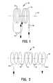
- FIG. 1is a schematic diagram of a first embodiment of a fiber sensing coil arrangement according to the invention
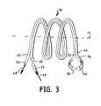
- FIG. 2is a schematic diagram of a second embodiment of a fiber sensing coil arrangement according to the invention.
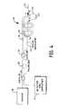
- FIG. 3is a schematic diagram of a third embodiment of a fiber sensing coil arrangement according to the invention.
- FIG. 4is a schematic diagram of a current sensor configuration using the fiber sensing coil arrangement of FIG. 3;
- FIG. 5is a schematic diagram of a conventional current sensor configuration.
- the inventionis directed to a novel fiber-optic (FO) coil configuration for a Faraday-type current sensor which is less susceptive to angular rotation, acceleration and vibrations.
- FOfiber-optic
- the FO coilcan be inserted at any location in the FO current sensing loop.
- a conventional fiber-optic sensor 10includes a light source 18 , which may be a broad-spectrum superluminecent source (SLS) exhibiting superluminescence or superfluorescence, as has been observed in high-gain laser materials which are operated below lasing threshold or as an essentially single-pass amplifier of spontaneous photons without the use of an optical resonator.
- SLSbroad-spectrum superluminecent source
- One example of an SLSis a superluminescent diode (SLD).
- SLSsuperluminescent fiber source
- SLSsuperluminescent fiber source
- the light sourcemay be polarized or unpolarized.
- a laser diode operating below lasing thresholdcan also be used.
- the light source 18is coupled to an input coupler 20 which is implemented as a directional coupler.
- a first portion of the light emerging from the input coupler 20is transmitted through a polarizer 28 which produces linearly polarized light.
- a second coupler 23launches two counter-propagating light beams into the respective ends of the fiber sensing coil 22 .
- ⁇ /4 wave plates 26 , 27are inserted between the source and the fiber sensing coil to convert the linearly polarized light into circularly polarized light.
- the phase of these counter-propagating light beamsis modulated by phase modulator 25 when the respective counter-propagating light beams enter or exit the fiber sensing coil 22 at the respective coil ends.
- a detector 12is coupled to a return tap of fiber coupler 20 and measures the optical power of the interference light produced by an interference of the counter-propagating light beams combined in fiber coupler 23 .
- each of the counter-propagating light beamsexperiences a Faraday rotation by the magnetic field produced by the electric current flowing through wire 24 , so that the optical power of the interference light is in first approximation proportional to the electric current.
- the interference lightalso includes, in addition to the desired current signal, components arising from a rotation or vibration of the FO sensing coil 22 , since in the Sagnac configuration the sensing coil 22 operates not only as a current sensor, but also as a gyroscope.
- the ⁇ /4 wave plates 26 , 27can be implemented, for example, as a polarization transformers of the type disclosed in the commonly assigned U.S. patent application Ser. No. 09/337,223 to Dyott. It will further be appreciated by those skilled in the art that the fiber sensing coil 22 is only representative of an optical waveguide configuration and that other optical waveguides, such as integrated waveguide structures, for example, thin film waveguides formed on a suitable substrate, may be used instead of or in addition to the optical fiber of the fiber sensing coil 22 .
- a FO current sensing coil 30which is less susceptive to vibrations and may be substituted for the fiber sensing coil 22 of FIG. 5, includes a first coil section 32 forming the current sensing coil and a second coil section 34 optically connected to the first coil section 32 and forming a compensation or “bucking” coil.
- the first coil section 32is formed of a first optical fiber, preferably a fiber having a low birefringence, which is wound in the form of a coil about a coil axis 39 with a first winding direction.
- the group velocity of the propagated radiationis independent of the polarization direction of the radiation. For this reason, coils made of low- or zero-birefringence fiber are commonly used for FO current sensors where the polarization state of the radiation is altered by the current-induced magnetic field.
- the second coil section 34is formed of a second optical fiber, preferably a fiber having a large birefringence, sometimes also referred to as polarization-maintaining (PM) fiber, which is wound in the form of a coil about essentially the same coil axis 39 , and encircling the current carrying conductor with a second winding direction opposite to the first winding direction.
- PMpolarization-maintaining
- the first optical fiber of the first coil section 32is connected in series to the second optical fiber of the second coil section 34 in such a way that, as viewed along the axis 39 , the optical radiation propagates, for example, through the first coil section 32 clockwise and then through the second coil section 34 counterclockwise.
- a first ⁇ /4 waveplate 38also referred to as a “polarization transformer”, is inserted between the sections 32 and 34 in a current-sensing configuration, and a second ⁇ /4 waveplate 36 is inserted at the other end of the first coil section 32 .
- the coil 30 formed of the two coil sections 32 , 34rotates or is subjected to vibrations, a phase shift induced in the first coil section 32 is compensated by a corresponding opposite phase change in the second coil, and vice versa, if both coil sections experience identical rotation/vibration characteristics. For this reason, the coil sections 32 , 34 are preferably intimately coupled to one another, as discussed below.
- FIG. 2depicts a second embodiment of the invention in which the bucking coil 34 is subdivided into two bucking coil sections 34 a and 34 b which can be arranged symmetrically with respect to the current sensing coil 32 to reduce asymmetric effects in the coil assembly 30 caused by the rotation or vibrations.
- the two bucking coil sections 34 a and 34 bare wound in the same direction, which is opposite to the winding direction of the current sensing coil 32 .
- ⁇ /4 wave plates 36 , 38are disposed proximate to the end sections of the current sensing coil 32 between the current sensing coil 32 and the bucking coil 34 (FIG. 1) or the respective bucking coil sections 34 a , 34 b (FIG. 2) to convert linearly polarized radiation to circularly polarized radiation, and vice versa, as discussed above.
- the coil 32 and the respective coil(s) 34 , 34 a, 34 bdo not have to be actually physically wound in opposite direction, but only have to be connected in such a way that the propagation direction of the radiation in those coils with respect to the axis 39 is reversed, as schematically shown in FIG. 1 .
- the coil section 32 and the respective coil(s) 34 , 34 a, 34 bcan be co-wound as a single strand coming from separate fiber stock, as indicated in FIG. 3 . In this way, the radiation experiences almost identical vibrational effects when traversing the coil 30 .
- Radiation entering the fiber of coil section 32for example, at the end 46 , first traverses one of the ⁇ /4 wave plates 36 , then passes through the sensing coil 32 made of low-birefringence fiber, reverses direction with respect to axis 39 in loop 40 which includes the other ⁇ /4 wave plate 38 , then enters the PM fiber 34 , and exits the PM fiber 34 at the end 48 .
- the counter-propagating beamtravels in the opposite direction, entering at end 48 and exiting at end 46 .
- fiber loop 40may be replaced with a fused fiber reflector or with a directional 3 dB coupler, which are known in the art and will not be further described at this point.
- a current sensor with reduced susceptibility to vibrations and sensor rotationincludes, like the current sensor of FIG. 5, a radiation source 18 , an input coupler 20 , and a polarizer 28 .
- a second coupler 23launches two counter-propagating light beams into the respective ends of the fiber sensing coil 30 having a reduced susceptibility to vibrations.
- FIG. 4shows the embodiment of coil 30 according to FIG. 3, although any of the current sensor coils illustrated in FIGS. 1-3 can be employed.
- the current sensorcan also be a reduced minimum configuration (RMC) current sensor of the type disclosed, for example, in commonly assigned U.S. patent application Ser. No. 09/615,166 to S. Bennett and R. Dyott, which is incorporated herein by reference.
- RMCreduced minimum configuration
Landscapes
- Engineering & Computer Science (AREA)
- Power Engineering (AREA)
- Physics & Mathematics (AREA)
- General Physics & Mathematics (AREA)
- Measuring Instrument Details And Bridges, And Automatic Balancing Devices (AREA)
Abstract
Description
Claims (16)
Priority Applications (1)
| Application Number | Priority Date | Filing Date | Title |
|---|---|---|---|
| US09/796,050US6703821B2 (en) | 2000-02-28 | 2001-02-28 | Faraday-effect current sensor with improved vibration response |
Applications Claiming Priority (2)
| Application Number | Priority Date | Filing Date | Title |
|---|---|---|---|
| US18567500P | 2000-02-28 | 2000-02-28 | |
| US09/796,050US6703821B2 (en) | 2000-02-28 | 2001-02-28 | Faraday-effect current sensor with improved vibration response |
Publications (2)
| Publication Number | Publication Date |
|---|---|
| US20020180416A1 US20020180416A1 (en) | 2002-12-05 |
| US6703821B2true US6703821B2 (en) | 2004-03-09 |
Family
ID=22681982
Family Applications (1)
| Application Number | Title | Priority Date | Filing Date |
|---|---|---|---|
| US09/796,050Expired - Fee RelatedUS6703821B2 (en) | 2000-02-28 | 2001-02-28 | Faraday-effect current sensor with improved vibration response |
Country Status (6)
| Country | Link |
|---|---|
| US (1) | US6703821B2 (en) |
| EP (1) | EP1261880B1 (en) |
| AT (1) | ATE265049T1 (en) |
| AU (1) | AU2001255167A1 (en) |
| DE (1) | DE60102906D1 (en) |
| WO (1) | WO2001063302A2 (en) |
Cited By (6)
| Publication number | Priority date | Publication date | Assignee | Title |
|---|---|---|---|---|
| US20020031292A1 (en)* | 2000-08-02 | 2002-03-14 | Richard Dyott | Reduction of linear birefringence in circular-cored single-mode fiber |
| US20070065156A1 (en)* | 2005-09-20 | 2007-03-22 | Hermann Lin | Fiber-optics multiplexed interferometric current sensor |
| US20090097796A1 (en)* | 2006-04-04 | 2009-04-16 | Lars Andersson | Fiber-Optic Current Sensor With Sum Detection |
| WO2009103126A1 (en)* | 2008-02-22 | 2009-08-27 | Smart Digital Optics Pty Limited | Sensing coil and sensing unit for sagnac optical fibre current sensor |
| US20100309473A1 (en)* | 2007-12-21 | 2010-12-09 | Honeywell International Inc. | Fiber optic current sensor and method for sensing current using the same |
| US20110052115A1 (en)* | 2009-08-27 | 2011-03-03 | General Electric Company | System and method for temperature control and compensation for fiber optic current sensing systems |
Families Citing this family (11)
| Publication number | Priority date | Publication date | Assignee | Title |
|---|---|---|---|---|
| US6891622B2 (en) | 1999-02-11 | 2005-05-10 | Kvh Industries, Inc. | Current sensor |
| CN102105959B (en)* | 2008-07-30 | 2014-11-26 | Abb研究有限公司 | Generator circuit breaker with fiber-optic current sensor |
| RU2481682C2 (en) | 2008-07-30 | 2013-05-10 | Абб Рисерч Лтд | Substation of ac to dc transformation or dc to high-voltage ac transformation with fibre-optic current sensor |
| CN103207301A (en)* | 2012-01-16 | 2013-07-17 | 中国科学院西安光学精密机械研究所 | Optical fiber current sensor coil and optical fiber current sensor based on coil |
| CN102608380B (en)* | 2012-02-29 | 2013-12-11 | 曲阜师范大学 | Self-induced photoelectric mixed current transformer |
| CN103453899A (en)* | 2012-06-03 | 2013-12-18 | 李卫 | Passive phase modulator for optical fiber gyroscope |
| EP3183585A1 (en) | 2014-08-19 | 2017-06-28 | ABB Schweiz AG | Optical sensor with spun birefringent sensing fiber |
| CN106154010B (en)* | 2015-03-30 | 2019-01-01 | 北京自动化控制设备研究所 | A kind of exoskeletal fiber-optic current sensor ring and preparation method thereof |
| CN111220881A (en)* | 2019-11-18 | 2020-06-02 | 南京航空航天大学 | Optical fiber detection device for detecting discharge fault of high-voltage bushing |
| US11371843B2 (en)* | 2020-07-02 | 2022-06-28 | Anello Photonics, Inc. | Integration of photonics optical gyroscopes with micro-electro-mechanical sensors |
| CN114577245B (en)* | 2022-03-22 | 2022-11-11 | 华中科技大学 | Optical fiber sensing system capable of simultaneously measuring current and vibration |
Citations (92)
| Publication number | Priority date | Publication date | Assignee | Title |
|---|---|---|---|---|
| US4372685A (en)* | 1979-01-15 | 1983-02-08 | Max-Planck-Gesellschaft Zur Forderung Der Wissenschaften E.V. | Method and arrangement for the measurement of rotations |
| FR2535463A1 (en) | 1982-10-28 | 1984-05-04 | Commissariat Energie Atomique | Device for measuring electric current based on the Faraday effect |
| DE3305104A1 (en) | 1983-02-15 | 1984-08-16 | Licentia Patent-Verwaltungs-Gmbh, 6000 Frankfurt | Fibre-optic polariser |
| US4571650A (en) | 1982-09-07 | 1986-02-18 | Hitachi, Ltd. | Magneto-optic information storage system utilizing a self-coupled laser |
| US4603931A (en) | 1984-12-14 | 1986-08-05 | Ruffman Samuel H | Anti-theft device for appliances with electrical AC power cords |
| US4615582A (en) | 1981-11-09 | 1986-10-07 | The Board Of Trustees Of The Leland Stanford Junior University | Magneto-optic rotator for providing additive Faraday rotations in a loop of optical fiber |
| US4630229A (en) | 1982-02-23 | 1986-12-16 | Intercontrole Societe Anonyme | Circuit for the fast calculation of the discrete Fourier transform of a signal |
| US4630890A (en) | 1983-06-22 | 1986-12-23 | At&T Bell Laboratories | Exposed core optical fibers, and method of making same |
| US4637722A (en) | 1983-04-25 | 1987-01-20 | The Board Of Trustees Of The Leland Stanford Junior University | Fiber optical rotation sensor with extended dynamic range |
| US4668264A (en) | 1982-08-02 | 1987-05-26 | Andrew Corporation | Method for making self-aligning optical fiber with accessible guiding region |
| US4669814A (en) | 1982-08-02 | 1987-06-02 | Andrew Corporation | Single mode, single polarization optical fiber with accessible guiding region and method of forming directional coupler using same |
| US4697876A (en) | 1983-02-25 | 1987-10-06 | Andrew Corporation | Fiber-optic rotation sensor |
| US4705399A (en) | 1984-06-14 | 1987-11-10 | Thomson-Csf | Device for measuring a nonreciprocal phase shift produced in a closed-loop interferometer |
| DE3615305A1 (en) | 1985-09-28 | 1987-11-12 | Licentia Gmbh | Process for producing a fibre-optical polariser |
| US4712866A (en) | 1986-07-24 | 1987-12-15 | Andrew Corporation | Indium-clad fiber-optic polarizer |
| US4733938A (en) | 1981-11-09 | 1988-03-29 | The Board Of Trustees Of The Leland Stanford Junior University | Magneto-optic rotator |
| US4740085A (en) | 1986-02-18 | 1988-04-26 | Northrop Corporation | Scale factor stability control |
| US4755021A (en) | 1982-08-02 | 1988-07-05 | Andrew Corporation | Self-aligning optical fiber directional coupler and fiber-ring optical rotation sensor using same |
| US4765739A (en) | 1985-11-06 | 1988-08-23 | Kabushiki Kaisha Toshiba | Fiber optical rotation sensor utilizing the Sagnac phase difference |
| US4776700A (en) | 1987-09-30 | 1988-10-11 | The United States Of America As Represented By The Secretary Of The Navy | Switched state fiber optic gyroscope |
| US4796993A (en) | 1987-04-13 | 1989-01-10 | Hitachi, Ltd. | Phase modulation type fiber optic gyroscope |
| US4815817A (en) | 1988-04-06 | 1989-03-28 | Raynet Corporation | D-shaped fiber |
| DE3742201A1 (en) | 1987-12-12 | 1989-06-22 | Teldix Gmbh | Fibre gyroscope |
| US4842409A (en) | 1985-05-30 | 1989-06-27 | Thomson-Csf | Monomode optical fiber ring interferometric device with semiconductor diode as light energy emission reception/amplification means |
| US4848910A (en) | 1987-06-11 | 1989-07-18 | Alsthom | Sagnac type optical fiber interferometer system |
| US4883358A (en) | 1987-09-02 | 1989-11-28 | Japan Aviation Electronics Industry Limited | Fiber optic gyro stabilized by harmonic components of detected signal |
| US4887900A (en) | 1987-02-20 | 1989-12-19 | Litton Systems, Inc. | Polarization maintaining fiber interferometer and method for source stabilization |
| US4943132A (en) | 1988-10-23 | 1990-07-24 | Huang Hung Chia | Passive fiber-optic polarization control |
| US5033854A (en) | 1989-12-06 | 1991-07-23 | Litton Systems, Inc. | Multiplexed fiberoptic gyro control |
| US5048962A (en) | 1989-05-15 | 1991-09-17 | Mitsubishi Precision Co., Ltd. | Optical gyro, signal processing apparatus for the same and method of driving phase modulator used in the same |
| US5056919A (en) | 1980-11-07 | 1991-10-15 | Thomson Csf | Device for measuring a phase shift which is not reciprocal produced in a ring interferometer |
| US5063290A (en)* | 1990-09-14 | 1991-11-05 | The United States Of America As Represented By The Secretary Of The Navy | All-optical fiber faraday rotation current sensor with heterodyne detection technique |
| US5074665A (en)* | 1989-12-21 | 1991-12-24 | Andrew Corporation | Fiber optic gyroscope using dual-section counter-wound coil |
| US5080489A (en) | 1989-03-29 | 1992-01-14 | Kubota, Ltd. | Fiber optic gyroscope for detecting angular velocity of rotation using equivalent time sampling |
| US5106193A (en) | 1990-08-09 | 1992-04-21 | The Board Of Trustees Of The Leland Stanford Junior University | Optical waveguide amplifier source gyroscope |
| US5133600A (en) | 1989-06-02 | 1992-07-28 | Litef Gmbh | Method and apparatus for demodulating the rotation rate signal of a fiber optic gyroscope |
| US5135555A (en) | 1989-12-21 | 1992-08-04 | At&T Bell Laboratories | Apparatus for fabrication of optical couplers |
| US5148236A (en) | 1990-06-18 | 1992-09-15 | Honeywell Inc. | Demodulation reference signal source |
| EP0551874A2 (en) | 1992-01-16 | 1993-07-21 | Japan Aviation Electronics Industry, Limited | Fiber optic gyro |
| US5289257A (en) | 1991-05-17 | 1994-02-22 | Mitsubishi Precision Co., Ltd. | Signal processing apparatus for optical gyro |
| US5289258A (en) | 1992-01-15 | 1994-02-22 | Honeywell Inc. | Fiber optic gyroscope modulation error reduction |
| EP0586242A1 (en) | 1992-09-02 | 1994-03-09 | Sumitomo Electric Industries, Ltd. | Fiber-optic gyroscope |
| US5331404A (en) | 1992-11-30 | 1994-07-19 | The United States Of America As Represented By The Secretary Of The Navy | Low noise fiber gyroscope system which includes excess noise subtraction |
| US5351123A (en) | 1992-01-13 | 1994-09-27 | Litef Gmbh | Method and apparatus for stabilizing control loop scale factor and gain in a fiber optic Sagnac interferometer |
| US5359413A (en) | 1992-01-13 | 1994-10-25 | Kearfott Guidance And Navigation Corporation | System for substantially eleminating lock-in in a ring laser gyroscope |
| US5365338A (en) | 1991-05-28 | 1994-11-15 | The United States Of America As Represented By The Secretary Of The Navy | Wavelength sensor for fiber optic gyroscope |
| US5406370A (en)* | 1993-02-26 | 1995-04-11 | The Board Of Trustees Of The Leland Stanford University | Winding technique for decreasing the pump power requirement of a brillouin fiber optic gyroscope |
| US5412471A (en) | 1991-03-12 | 1995-05-02 | Mitsubishi Precision Co., Ltd. | Optical gyro with expanded detectable range of input rotation angular velocity and optical waveguide-type phase modulator used in the same |
| JPH07209398A (en) | 1994-01-24 | 1995-08-11 | Nissin Electric Co Ltd | Faraday effect type optical fiber sensor and current transformer |
| US5457532A (en) | 1994-05-31 | 1995-10-10 | Honeywell Inc. | Harmonic phase modulation error reducer |
| US5459575A (en) | 1993-02-27 | 1995-10-17 | British Aerospace Plc | Laser fiber optic gyroscope having phase modulation |
| US5469267A (en) | 1994-04-08 | 1995-11-21 | The University Of Rochester | Halftone correction system |
| US5469257A (en) | 1993-11-24 | 1995-11-21 | Honeywell Inc. | Fiber optic gyroscope output noise reducer |
| US5471301A (en) | 1993-08-23 | 1995-11-28 | Hitachi Cable, Ltd. | Optical fiber gyro |
| US5475772A (en) | 1994-06-02 | 1995-12-12 | Honeywell Inc. | Spatial filter for improving polarization extinction ratio in a proton exchange wave guide device |
| EP0686867A1 (en) | 1994-06-09 | 1995-12-13 | CeramOptec GmbH | All fiber in-line optical isolator |
| US5493396A (en) | 1993-11-30 | 1996-02-20 | Honeywell Inc. | High resolution ring laser gyroscope readout |
| US5500909A (en) | 1993-02-17 | 1996-03-19 | Abb Research Ltd. | Sensor head for a fiber-optic current measuring device |
| US5504684A (en) | 1993-12-10 | 1996-04-02 | Trimble Navigation Limited | Single-chip GPS receiver digital signal processing and microcomputer |
| US5513003A (en) | 1994-06-06 | 1996-04-30 | Honeywell Inc. | Fiber optic gyro digital control with rate extension |
| EP0722081A2 (en) | 1990-03-19 | 1996-07-17 | Eli Lilly And Company | Fiberoptic interferometric sensor |
| US5552887A (en) | 1995-04-07 | 1996-09-03 | Andrew Corporation | Fiber optic rotation sensor or gyroscope with improved sensing coil |
| US5602642A (en)* | 1995-06-07 | 1997-02-11 | Honeywell Inc. | Magnetically insensitive fiber optic rotation sensor |
| US5644397A (en) | 1994-10-07 | 1997-07-01 | The Texas A&M University System | Fiber optic interferometric circuit and magnetic field sensor |
| US5654906A (en) | 1995-07-06 | 1997-08-05 | Youngquist; John S. | Rate gyro error correction and use as heading source |
| US5655035A (en) | 1995-11-16 | 1997-08-05 | Alliedsignal Inc. | Differential fiber optic angular rate sensor for minimizing common mode noise in the sensor output |
| US5682241A (en) | 1996-03-11 | 1997-10-28 | Litton Systems, Inc. | Method and apparatus for overcoming cross-coupling in a fiber optic gyroscope employing overmodulation |
| US5696858A (en) | 1996-08-01 | 1997-12-09 | The Texas A&M University System | Fiber Optics apparatus and method for accurate current sensing |
| US5701376A (en) | 1995-07-26 | 1997-12-23 | Fujitsu Limited | Polarized-wave-dispersion- preventive optical fiber and its manufacturing method |
| US5701177A (en) | 1993-11-16 | 1997-12-23 | Hitachi Cable, Ltd. | Method for detecting fault of optical fiber gyro and apparatus for diagnosing fault of the same |
| US5767509A (en) | 1996-12-24 | 1998-06-16 | Litton Systems, Inc. | Fiber optic sensor coil including buffer regions |
| US5781675A (en) | 1997-03-14 | 1998-07-14 | National Science Council | Method for preparing fiber-optic polarizer |
| EP0856737A1 (en) | 1997-01-29 | 1998-08-05 | Abb Research Ltd. | Magneto optical current sensor |
| EP0872756A1 (en) | 1997-04-14 | 1998-10-21 | BRITISH TELECOMMUNICATIONS public limited company | Optical modulator |
| WO1998058268A1 (en) | 1997-06-19 | 1998-12-23 | The Texas A & M University System | Fiber optic interferometric sensor |
| US5854864A (en) | 1996-07-16 | 1998-12-29 | The Regents Of The University Of California | In-line polymeric construct for modulators, filters, switches and other electro-optic devices |
| US5898496A (en) | 1997-02-14 | 1999-04-27 | Allied Signal Inc | Optical signal noise reduction for fiber optic gyroscopses |
| US5946097A (en) | 1997-12-31 | 1999-08-31 | Honeywell Inc. | Vibration rectification error reducer for fiber optic gyroscope |
| US5987195A (en) | 1996-08-01 | 1999-11-16 | The Texas A&M University System | Fiber optics apparatus and method for accurate current sensing |
| US6025915A (en) | 1998-06-25 | 2000-02-15 | Litton Systems, Inc. | Scale factor stabilization of a broadband fiber source used in fiber optic gyroscopes in radiation environments |
| US6075915A (en) | 1997-03-29 | 2000-06-13 | Koops; Hans W. P. | In-fiber photonic crystals and systems |
| WO2000036425A2 (en) | 1998-11-12 | 2000-06-22 | Honeywell Inc. | Fiber optic current sensor having rotation immunity |
| US6148131A (en) | 1995-08-16 | 2000-11-14 | Plasma Optical Fibre B.V. | Method of making a twisted optical fiber with low polarization mode dispersion |
| US6163632A (en) | 1997-09-23 | 2000-12-19 | Bookham Technology Plc | Integrated optical circuit |
| US6185033B1 (en) | 1998-03-30 | 2001-02-06 | France Telecom | Hybrid integrated electro-optical modulator of the pockels effect type |
| US6188811B1 (en) | 1998-10-31 | 2001-02-13 | The Texas A&M Universtiy System | Fiber optic current sensor |
| US6233371B1 (en) | 1997-05-22 | 2001-05-15 | Donam Systems Inc. | Optical fiber polarization controller |
| US6307632B1 (en) | 1999-03-24 | 2001-10-23 | The Texas A&M University System | Magnetic field integrated fiber optic sensor with improved sensitivity |
| US6351310B1 (en) | 1996-04-19 | 2002-02-26 | Kvh Industries, Inc. | Reduced minimum configuration interferometric fiber optic gyroscope with simplified signal processing electronics |
| US6370289B1 (en) | 2000-01-12 | 2002-04-09 | Kvh Industries, Inc. | Apparatus and method for electronic RIN reduction in fiber-optic sensors |
| US6434285B1 (en) | 1998-12-31 | 2002-08-13 | Nxtphase Technologies Srl | Fiber optic difference current sensor |
| US6535654B1 (en) | 1998-12-29 | 2003-03-18 | Nxtphase Technologies, Srl | Method for fabrication of an all fiber polarization retardation device |
- 2001
- 2001-02-28USUS09/796,050patent/US6703821B2/ennot_activeExpired - Fee Related
- 2001-02-28EPEP01928293Apatent/EP1261880B1/ennot_activeExpired - Lifetime
- 2001-02-28DEDE60102906Tpatent/DE60102906D1/ennot_activeExpired - Lifetime
- 2001-02-28WOPCT/US2001/006404patent/WO2001063302A2/enactiveIP Right Grant
- 2001-02-28ATAT01928293Tpatent/ATE265049T1/ennot_activeIP Right Cessation
- 2001-02-28AUAU2001255167Apatent/AU2001255167A1/ennot_activeAbandoned
Patent Citations (100)
| Publication number | Priority date | Publication date | Assignee | Title |
|---|---|---|---|---|
| US4372685A (en)* | 1979-01-15 | 1983-02-08 | Max-Planck-Gesellschaft Zur Forderung Der Wissenschaften E.V. | Method and arrangement for the measurement of rotations |
| US5056919A (en) | 1980-11-07 | 1991-10-15 | Thomson Csf | Device for measuring a phase shift which is not reciprocal produced in a ring interferometer |
| US4733938A (en) | 1981-11-09 | 1988-03-29 | The Board Of Trustees Of The Leland Stanford Junior University | Magneto-optic rotator |
| US4615582A (en) | 1981-11-09 | 1986-10-07 | The Board Of Trustees Of The Leland Stanford Junior University | Magneto-optic rotator for providing additive Faraday rotations in a loop of optical fiber |
| US4630229A (en) | 1982-02-23 | 1986-12-16 | Intercontrole Societe Anonyme | Circuit for the fast calculation of the discrete Fourier transform of a signal |
| US4668264A (en) | 1982-08-02 | 1987-05-26 | Andrew Corporation | Method for making self-aligning optical fiber with accessible guiding region |
| US4669814A (en) | 1982-08-02 | 1987-06-02 | Andrew Corporation | Single mode, single polarization optical fiber with accessible guiding region and method of forming directional coupler using same |
| US4755021A (en) | 1982-08-02 | 1988-07-05 | Andrew Corporation | Self-aligning optical fiber directional coupler and fiber-ring optical rotation sensor using same |
| US4571650A (en) | 1982-09-07 | 1986-02-18 | Hitachi, Ltd. | Magneto-optic information storage system utilizing a self-coupled laser |
| FR2535463A1 (en) | 1982-10-28 | 1984-05-04 | Commissariat Energie Atomique | Device for measuring electric current based on the Faraday effect |
| DE3305104A1 (en) | 1983-02-15 | 1984-08-16 | Licentia Patent-Verwaltungs-Gmbh, 6000 Frankfurt | Fibre-optic polariser |
| US4697876A (en) | 1983-02-25 | 1987-10-06 | Andrew Corporation | Fiber-optic rotation sensor |
| US4637722A (en) | 1983-04-25 | 1987-01-20 | The Board Of Trustees Of The Leland Stanford Junior University | Fiber optical rotation sensor with extended dynamic range |
| US4630890A (en) | 1983-06-22 | 1986-12-23 | At&T Bell Laboratories | Exposed core optical fibers, and method of making same |
| US4705399A (en) | 1984-06-14 | 1987-11-10 | Thomson-Csf | Device for measuring a nonreciprocal phase shift produced in a closed-loop interferometer |
| US4603931A (en) | 1984-12-14 | 1986-08-05 | Ruffman Samuel H | Anti-theft device for appliances with electrical AC power cords |
| US4842409A (en) | 1985-05-30 | 1989-06-27 | Thomson-Csf | Monomode optical fiber ring interferometric device with semiconductor diode as light energy emission reception/amplification means |
| DE3615305A1 (en) | 1985-09-28 | 1987-11-12 | Licentia Gmbh | Process for producing a fibre-optical polariser |
| US4765739A (en) | 1985-11-06 | 1988-08-23 | Kabushiki Kaisha Toshiba | Fiber optical rotation sensor utilizing the Sagnac phase difference |
| US4740085A (en) | 1986-02-18 | 1988-04-26 | Northrop Corporation | Scale factor stability control |
| US4712866A (en) | 1986-07-24 | 1987-12-15 | Andrew Corporation | Indium-clad fiber-optic polarizer |
| US4887900A (en) | 1987-02-20 | 1989-12-19 | Litton Systems, Inc. | Polarization maintaining fiber interferometer and method for source stabilization |
| US4796993A (en) | 1987-04-13 | 1989-01-10 | Hitachi, Ltd. | Phase modulation type fiber optic gyroscope |
| US4848910A (en) | 1987-06-11 | 1989-07-18 | Alsthom | Sagnac type optical fiber interferometer system |
| US4883358A (en) | 1987-09-02 | 1989-11-28 | Japan Aviation Electronics Industry Limited | Fiber optic gyro stabilized by harmonic components of detected signal |
| US4776700A (en) | 1987-09-30 | 1988-10-11 | The United States Of America As Represented By The Secretary Of The Navy | Switched state fiber optic gyroscope |
| DE3742201A1 (en) | 1987-12-12 | 1989-06-22 | Teldix Gmbh | Fibre gyroscope |
| US4815817A (en) | 1988-04-06 | 1989-03-28 | Raynet Corporation | D-shaped fiber |
| US4943132A (en) | 1988-10-23 | 1990-07-24 | Huang Hung Chia | Passive fiber-optic polarization control |
| US5096312A (en) | 1988-10-23 | 1992-03-17 | Huang Hung Chia | Passive fiber-optic polarization control element |
| US5080489A (en) | 1989-03-29 | 1992-01-14 | Kubota, Ltd. | Fiber optic gyroscope for detecting angular velocity of rotation using equivalent time sampling |
| US5048962A (en) | 1989-05-15 | 1991-09-17 | Mitsubishi Precision Co., Ltd. | Optical gyro, signal processing apparatus for the same and method of driving phase modulator used in the same |
| US5133600A (en) | 1989-06-02 | 1992-07-28 | Litef Gmbh | Method and apparatus for demodulating the rotation rate signal of a fiber optic gyroscope |
| US5033854A (en) | 1989-12-06 | 1991-07-23 | Litton Systems, Inc. | Multiplexed fiberoptic gyro control |
| US5074665A (en)* | 1989-12-21 | 1991-12-24 | Andrew Corporation | Fiber optic gyroscope using dual-section counter-wound coil |
| US5135555A (en) | 1989-12-21 | 1992-08-04 | At&T Bell Laboratories | Apparatus for fabrication of optical couplers |
| EP0722081A2 (en) | 1990-03-19 | 1996-07-17 | Eli Lilly And Company | Fiberoptic interferometric sensor |
| US5148236A (en) | 1990-06-18 | 1992-09-15 | Honeywell Inc. | Demodulation reference signal source |
| US5106193A (en) | 1990-08-09 | 1992-04-21 | The Board Of Trustees Of The Leland Stanford Junior University | Optical waveguide amplifier source gyroscope |
| US5063290A (en)* | 1990-09-14 | 1991-11-05 | The United States Of America As Represented By The Secretary Of The Navy | All-optical fiber faraday rotation current sensor with heterodyne detection technique |
| US5412471A (en) | 1991-03-12 | 1995-05-02 | Mitsubishi Precision Co., Ltd. | Optical gyro with expanded detectable range of input rotation angular velocity and optical waveguide-type phase modulator used in the same |
| US5289257A (en) | 1991-05-17 | 1994-02-22 | Mitsubishi Precision Co., Ltd. | Signal processing apparatus for optical gyro |
| US5365338A (en) | 1991-05-28 | 1994-11-15 | The United States Of America As Represented By The Secretary Of The Navy | Wavelength sensor for fiber optic gyroscope |
| US5351123A (en) | 1992-01-13 | 1994-09-27 | Litef Gmbh | Method and apparatus for stabilizing control loop scale factor and gain in a fiber optic Sagnac interferometer |
| US5359413A (en) | 1992-01-13 | 1994-10-25 | Kearfott Guidance And Navigation Corporation | System for substantially eleminating lock-in in a ring laser gyroscope |
| US5289258A (en) | 1992-01-15 | 1994-02-22 | Honeywell Inc. | Fiber optic gyroscope modulation error reduction |
| EP0551874A2 (en) | 1992-01-16 | 1993-07-21 | Japan Aviation Electronics Industry, Limited | Fiber optic gyro |
| EP0586242A1 (en) | 1992-09-02 | 1994-03-09 | Sumitomo Electric Industries, Ltd. | Fiber-optic gyroscope |
| US5331404A (en) | 1992-11-30 | 1994-07-19 | The United States Of America As Represented By The Secretary Of The Navy | Low noise fiber gyroscope system which includes excess noise subtraction |
| US5500909A (en) | 1993-02-17 | 1996-03-19 | Abb Research Ltd. | Sensor head for a fiber-optic current measuring device |
| US5406370A (en)* | 1993-02-26 | 1995-04-11 | The Board Of Trustees Of The Leland Stanford University | Winding technique for decreasing the pump power requirement of a brillouin fiber optic gyroscope |
| US5459575A (en) | 1993-02-27 | 1995-10-17 | British Aerospace Plc | Laser fiber optic gyroscope having phase modulation |
| US5471301A (en) | 1993-08-23 | 1995-11-28 | Hitachi Cable, Ltd. | Optical fiber gyro |
| US5701177A (en) | 1993-11-16 | 1997-12-23 | Hitachi Cable, Ltd. | Method for detecting fault of optical fiber gyro and apparatus for diagnosing fault of the same |
| US5469257A (en) | 1993-11-24 | 1995-11-21 | Honeywell Inc. | Fiber optic gyroscope output noise reducer |
| US5493396A (en) | 1993-11-30 | 1996-02-20 | Honeywell Inc. | High resolution ring laser gyroscope readout |
| US5504684A (en) | 1993-12-10 | 1996-04-02 | Trimble Navigation Limited | Single-chip GPS receiver digital signal processing and microcomputer |
| JPH07209398A (en) | 1994-01-24 | 1995-08-11 | Nissin Electric Co Ltd | Faraday effect type optical fiber sensor and current transformer |
| US5469267A (en) | 1994-04-08 | 1995-11-21 | The University Of Rochester | Halftone correction system |
| US5559908A (en) | 1994-05-31 | 1996-09-24 | Honeywell Inc. | Method for damping optical fiber on a bias optical phase modulator |
| US5457532A (en) | 1994-05-31 | 1995-10-10 | Honeywell Inc. | Harmonic phase modulation error reducer |
| US5475772A (en) | 1994-06-02 | 1995-12-12 | Honeywell Inc. | Spatial filter for improving polarization extinction ratio in a proton exchange wave guide device |
| US5513003A (en) | 1994-06-06 | 1996-04-30 | Honeywell Inc. | Fiber optic gyro digital control with rate extension |
| EP0686867A1 (en) | 1994-06-09 | 1995-12-13 | CeramOptec GmbH | All fiber in-line optical isolator |
| US5644397A (en) | 1994-10-07 | 1997-07-01 | The Texas A&M University System | Fiber optic interferometric circuit and magnetic field sensor |
| US5552887A (en) | 1995-04-07 | 1996-09-03 | Andrew Corporation | Fiber optic rotation sensor or gyroscope with improved sensing coil |
| US5602642A (en)* | 1995-06-07 | 1997-02-11 | Honeywell Inc. | Magnetically insensitive fiber optic rotation sensor |
| US5654906A (en) | 1995-07-06 | 1997-08-05 | Youngquist; John S. | Rate gyro error correction and use as heading source |
| US5701376A (en) | 1995-07-26 | 1997-12-23 | Fujitsu Limited | Polarized-wave-dispersion- preventive optical fiber and its manufacturing method |
| US6148131A (en) | 1995-08-16 | 2000-11-14 | Plasma Optical Fibre B.V. | Method of making a twisted optical fiber with low polarization mode dispersion |
| US5655035A (en) | 1995-11-16 | 1997-08-05 | Alliedsignal Inc. | Differential fiber optic angular rate sensor for minimizing common mode noise in the sensor output |
| US5682241A (en) | 1996-03-11 | 1997-10-28 | Litton Systems, Inc. | Method and apparatus for overcoming cross-coupling in a fiber optic gyroscope employing overmodulation |
| EP0871009A1 (en) | 1996-03-11 | 1998-10-14 | Litton Systems | Rotation rate measurement and fiber optic gyroscopes |
| US6351310B1 (en) | 1996-04-19 | 2002-02-26 | Kvh Industries, Inc. | Reduced minimum configuration interferometric fiber optic gyroscope with simplified signal processing electronics |
| US6047095A (en) | 1996-07-16 | 2000-04-04 | The Regents Of The University Of California | In-line polymeric construct for modulators, filters, switches and other electro-optic devices |
| US5854864A (en) | 1996-07-16 | 1998-12-29 | The Regents Of The University Of California | In-line polymeric construct for modulators, filters, switches and other electro-optic devices |
| US5696858A (en) | 1996-08-01 | 1997-12-09 | The Texas A&M University System | Fiber Optics apparatus and method for accurate current sensing |
| US5987195A (en) | 1996-08-01 | 1999-11-16 | The Texas A&M University System | Fiber optics apparatus and method for accurate current sensing |
| US5767509A (en) | 1996-12-24 | 1998-06-16 | Litton Systems, Inc. | Fiber optic sensor coil including buffer regions |
| EP0856737A1 (en) | 1997-01-29 | 1998-08-05 | Abb Research Ltd. | Magneto optical current sensor |
| US5953121A (en)* | 1997-01-29 | 1999-09-14 | Abb Research Ltd. | Magneto-optic current sensor having a mechanically stress-free λ/4 element |
| US5898496A (en) | 1997-02-14 | 1999-04-27 | Allied Signal Inc | Optical signal noise reduction for fiber optic gyroscopses |
| US5781675A (en) | 1997-03-14 | 1998-07-14 | National Science Council | Method for preparing fiber-optic polarizer |
| US6075915A (en) | 1997-03-29 | 2000-06-13 | Koops; Hans W. P. | In-fiber photonic crystals and systems |
| EP0872756A1 (en) | 1997-04-14 | 1998-10-21 | BRITISH TELECOMMUNICATIONS public limited company | Optical modulator |
| US6233371B1 (en) | 1997-05-22 | 2001-05-15 | Donam Systems Inc. | Optical fiber polarization controller |
| WO1998058268A1 (en) | 1997-06-19 | 1998-12-23 | The Texas A & M University System | Fiber optic interferometric sensor |
| US6023331A (en) | 1997-06-19 | 2000-02-08 | The Texas A&M University System | Fiber optic interferometric sensor and method by adding controlled amounts of circular birefringence in the sensing fiber |
| US6163632A (en) | 1997-09-23 | 2000-12-19 | Bookham Technology Plc | Integrated optical circuit |
| US5946097A (en) | 1997-12-31 | 1999-08-31 | Honeywell Inc. | Vibration rectification error reducer for fiber optic gyroscope |
| US6185033B1 (en) | 1998-03-30 | 2001-02-06 | France Telecom | Hybrid integrated electro-optical modulator of the pockels effect type |
| US6025915A (en) | 1998-06-25 | 2000-02-15 | Litton Systems, Inc. | Scale factor stabilization of a broadband fiber source used in fiber optic gyroscopes in radiation environments |
| US6188811B1 (en) | 1998-10-31 | 2001-02-13 | The Texas A&M Universtiy System | Fiber optic current sensor |
| US6301400B1 (en) | 1998-11-12 | 2001-10-09 | Nxtphase Technologies Srl | Fiber optic current sensor having rotation immunity |
| WO2000036425A2 (en) | 1998-11-12 | 2000-06-22 | Honeywell Inc. | Fiber optic current sensor having rotation immunity |
| US6535654B1 (en) | 1998-12-29 | 2003-03-18 | Nxtphase Technologies, Srl | Method for fabrication of an all fiber polarization retardation device |
| US6434285B1 (en) | 1998-12-31 | 2002-08-13 | Nxtphase Technologies Srl | Fiber optic difference current sensor |
| US6307632B1 (en) | 1999-03-24 | 2001-10-23 | The Texas A&M University System | Magnetic field integrated fiber optic sensor with improved sensitivity |
| US6356351B1 (en) | 1999-03-24 | 2002-03-12 | The Texas A&M University System | Fiber-optic current sensor with improved isolation |
| US6370289B1 (en) | 2000-01-12 | 2002-04-09 | Kvh Industries, Inc. | Apparatus and method for electronic RIN reduction in fiber-optic sensors |
Non-Patent Citations (23)
| Title |
|---|
| Alekseev et al; "Fiber Optic Gyroscope with Suppression of Excess Noise from the Radiation Source", Technical Physical Letters, 24(9): 719-721, (Sep. 1998). |
| Blake and Szafraniec, "Random Noise in PM and Depolarized Fiber Gyros", OSA Symposium Proceedings, 1997, OWB2, pp. 122-125. (no month). |
| Blake et al., "In-Line Sagnac Interferometer Current Sensor," IEEE, pp. 116-121 (1995). (no month). |
| Bohnert. et al., "Field Test of Interferometric Optical Fiber High-Voltage and Current Sensors" SPIE, vol. 2360 pp. 16-19 (Feb. 1994). |
| Bohnert. et al., "Temperature and Vibration Insensitive Fiber-Optic Current Sensor" ABB, vol. 2360 pp. 336-339 (Feb. 1994). |
| Burns, et al., "Excess Noise in Fiber in Gyroscope Sources", IEEE Photonics Technology Letter, vol. 2, No. 8, Aug. 1990, pp. 606-608. |
| Clark et al., "Application of a PLL and ALL Noise Reduction Process in Optical Sensing System," IEEE Translations on Industrial Electronics, vol. 44, No. 1, Feb. 1997, pp. 136-138. |
| Dagenais et al., "Low-Frequency Intensity Noise Reduction for Fiber-Optic Sensor Applications," Optical Fiber Sensors Conference, 1992, Jan. 29-31, pp. 177-180. |
| Dupraz, J.P., "Fiber-Optic Interferometers for Current Measurement: Principles and Technology", Alsthom Review No. 9:29-44 (Dec. 1987). |
| Frosio, G. and Dändliker, "Reciprocal Reflection Interferometer for a Fiber-Optic Faraday Current Sensor", Applied Optics 33 (25): 6111-6122 (Sep. 1, 1994). |
| Gronau Yuval et al.; "Digital Signal Processing For an Open-Loop Fiber-Optic Gyroscope", Applied Optics, Optical Society of America, Washington, U.S., vol. 34, No. 25, Sep. 1, 1995, pp. 5849-5853. |
| Killian M. Kevin; "Pointing Grade Fiber Optic Gyroscope", IEEE AES Systems Magazine, pp. 6-10 (Jul. 1994). |
| Lafevre, "The Fiber-Optic Gyroscope", Artech House, Boston, pp. 29-30 (1993). (no month). |
| LaViolette and Bossler: "Phase Modulation Control for An Interferometric Fiber Optic Gyroscope", IEEE Plan 90, Position Location and Navigation Symposium, Las Vegas, (Mar. 20-23, 1990). |
| McCallion and Shimazu; "Side-Polished Fiber Provides Functionality and Transparency", Laser Focus World, 34 (9): S19-S24, (Sep. 1, 1998). |
| Moeller and Burns, "1.06mm All-fiber Gyroscope with Noise Subtraction Proceedings of the Conference on Optical Fiber Sensors", IEEE-OSA, Monterey, CA, 1992, pp. 82-85 (no month). |
| Moeller and Burns, "Observation of Thermal Noise in a Dynamically Biased Fiber-Optic Gyro", Optical Letters, 1996, vol. 21, pp. 171-173. (no month). |
| Nikos Drakos, "Circularization States for Light, and Quarter-Wave Plates," Computer Based Learning Unit, University of Leeds, Mar. 2, 1998). |
| Ono et al.; "A Small-Sized, Compact, Open-loop Fibre-Optic Gyroscope with Stabilized Scale Factor", Meas. Sci. Technol. 1: 1078-1083, (1990 (no month). |
| Polynkin et al.; "All-Optical Noise-Subtraction Scheme for a Fiber-Optic Gyroscope", Optics Letters, 25(3): 147-149, (Feb. 1, 2000). |
| Rabelo et al.; "SNR Enhancement of Intensity Noise-Limited FOGs", Journal of Lightwave Technology 18(12):2146-2150 (Dec. 2000). |
| Short, S. et al., "Elimination of Birefringence Induced Scale Factor Errors in the In-Line Sagnac Interferometer Current Sensor", Journal of Lightwave Technology 16 (10): 1844-1850 (Oct. 1998). |
| US 6,208,775, 3/2001, Dyott (withdrawn) |
Cited By (13)
| Publication number | Priority date | Publication date | Assignee | Title |
|---|---|---|---|---|
| US7120323B2 (en) | 2000-08-02 | 2006-10-10 | Kvh Industries, Inc. | Reduction of linear birefringence in circular-cored single-mode fiber |
| US20020031292A1 (en)* | 2000-08-02 | 2002-03-14 | Richard Dyott | Reduction of linear birefringence in circular-cored single-mode fiber |
| US20070065156A1 (en)* | 2005-09-20 | 2007-03-22 | Hermann Lin | Fiber-optics multiplexed interferometric current sensor |
| US7876448B2 (en)* | 2006-04-04 | 2011-01-25 | Abb Research Ltd. | Fiber-optic current sensor with sum detection |
| US20090097796A1 (en)* | 2006-04-04 | 2009-04-16 | Lars Andersson | Fiber-Optic Current Sensor With Sum Detection |
| CN101449174A (en)* | 2006-04-04 | 2009-06-03 | Abb研究有限公司 | Fiber optic current sensor with summing detection |
| CN101449174B (en)* | 2006-04-04 | 2013-07-17 | Abb研究有限公司 | Optical fiber current sensor having sum detection |
| US20100309473A1 (en)* | 2007-12-21 | 2010-12-09 | Honeywell International Inc. | Fiber optic current sensor and method for sensing current using the same |
| US20110051145A1 (en)* | 2008-02-22 | 2011-03-03 | Smart Digital Optics Pty Limited | Sensing coil and sensing unit for sagnac optical fibre current sensor |
| AU2009217236B2 (en)* | 2008-02-22 | 2013-06-13 | Smart Digital Optics Pty Limited | Sensing coil and sensing unit for Sagnac optical fibre current sensor |
| WO2009103126A1 (en)* | 2008-02-22 | 2009-08-27 | Smart Digital Optics Pty Limited | Sensing coil and sensing unit for sagnac optical fibre current sensor |
| US8542366B2 (en) | 2008-02-22 | 2013-09-24 | Smart Digital Optics Pty Limited | Sensing coil and sensing unit for sagnac optical fibre current sensor |
| US20110052115A1 (en)* | 2009-08-27 | 2011-03-03 | General Electric Company | System and method for temperature control and compensation for fiber optic current sensing systems |
Also Published As
| Publication number | Publication date |
|---|---|
| EP1261880B1 (en) | 2004-04-21 |
| ATE265049T1 (en) | 2004-05-15 |
| DE60102906D1 (en) | 2004-05-27 |
| US20020180416A1 (en) | 2002-12-05 |
| WO2001063302A3 (en) | 2002-02-28 |
| EP1261880A2 (en) | 2002-12-04 |
| WO2001063302A2 (en) | 2001-08-30 |
| AU2001255167A1 (en) | 2001-09-03 |
Similar Documents
| Publication | Publication Date | Title |
|---|---|---|
| US6703821B2 (en) | Faraday-effect current sensor with improved vibration response | |
| US6636321B2 (en) | Fiber-optic current sensor | |
| KR101408556B1 (en) | Fiber optic current sensor | |
| US5953121A (en) | Magneto-optic current sensor having a mechanically stress-free λ/4 element | |
| US6801319B2 (en) | Symmetrical depolarized fiber optic gyroscope | |
| CN107003343B (en) | Optical sensor with rotating birefringent sensing fiber | |
| US20010050551A1 (en) | Fiber optic current sensor | |
| US6891622B2 (en) | Current sensor | |
| US20110074393A1 (en) | Temperature compensated fiber optic current or magnetic field sensor with insensitivity to variations in sensor parameters | |
| EP0520282B1 (en) | Fiber optic gyro | |
| EP0783701B1 (en) | Optical interferometric current sensor and a method for measuring an electrical current | |
| US6211963B1 (en) | Low drift depolarizer for fiber optic gyroscope having legs wound in a winding pattern | |
| EP2230484A1 (en) | Depolarizer for a fiber optic gyroscope (fog) using high birefringence photonic crystal fiber | |
| JP2002054933A (en) | Optical fiber gyro | |
| Blake | Current sensors based on the Sagnac interferometer | |
| JP2627134B2 (en) | Fiber optic gyro | |
| JP2514482B2 (en) | Fiber optic gyro | |
| US20020001426A1 (en) | Current sensor | |
| Blake et al. | All-fiber in-line Sagnac interferometer current sensor | |
| JPH08145696A (en) | Fiber optic gyroscope | |
| JPH0510770A (en) | Optical rotation detector |
Legal Events
| Date | Code | Title | Description |
|---|---|---|---|
| AS | Assignment | Owner name:KVH INDUSTRIES, INC., RHODE ISLAND Free format text:ASSIGNMENT OF ASSIGNORS INTEREST;ASSIGNOR:DYOTT, RICHARD B.;REEL/FRAME:014165/0140 Effective date:20030611 | |
| AS | Assignment | Owner name:FLEET CAPITAL CORPORATION, MASSACHUSETTS Free format text:NEGATIVE PLEDGE AGREEMENT;ASSIGNOR:KVH INDUSTRIES, INC.;REEL/FRAME:014615/0595 Effective date:20030717 | |
| FPAY | Fee payment | Year of fee payment:4 | |
| REMI | Maintenance fee reminder mailed | ||
| REMI | Maintenance fee reminder mailed | ||
| LAPS | Lapse for failure to pay maintenance fees | ||
| STCH | Information on status: patent discontinuation | Free format text:PATENT EXPIRED DUE TO NONPAYMENT OF MAINTENANCE FEES UNDER 37 CFR 1.362 | |
| FP | Lapsed due to failure to pay maintenance fee | Effective date:20120309 | |
| AS | Assignment | Owner name:BANK OF AMERICA N.A., WASHINGTON Free format text:SECURITY INTEREST;ASSIGNOR:KVH INDUSTRIES, INC.;REEL/FRAME:033280/0942 Effective date:20140702 | |
| AS | Assignment | Owner name:KVH INDUSTRIES, INC., RHODE ISLAND Free format text:RELEASE OF SECURITY INTEREST;ASSIGNOR:BANK OF AMERICA, N.A. (FORMERLY FLEET NATIONAL BANK);REEL/FRAME:033421/0054 Effective date:20140714 |