US6703716B2 - Permanent magnet generator for bicycle light operation - Google Patents
Permanent magnet generator for bicycle light operationDownload PDFInfo
- Publication number
- US6703716B2 US6703716B2US09/977,964US97796401AUS6703716B2US 6703716 B2US6703716 B2US 6703716B2US 97796401 AUS97796401 AUS 97796401AUS 6703716 B2US6703716 B2US 6703716B2
- Authority
- US
- United States
- Prior art keywords
- bicycle
- generator
- stator
- extending
- bearings
- Prior art date
- Legal status (The legal status is an assumption and is not a legal conclusion. Google has not performed a legal analysis and makes no representation as to the accuracy of the status listed.)
- Expired - Fee Related, expires
Links
Images


Classifications
- B—PERFORMING OPERATIONS; TRANSPORTING
- B62—LAND VEHICLES FOR TRAVELLING OTHERWISE THAN ON RAILS
- B62J—CYCLE SADDLES OR SEATS; AUXILIARY DEVICES OR ACCESSORIES SPECIALLY ADAPTED TO CYCLES AND NOT OTHERWISE PROVIDED FOR, e.g. ARTICLE CARRIERS OR CYCLE PROTECTORS
- B62J6/00—Arrangement of optical signalling or lighting devices on cycles; Mounting or supporting thereof; Circuits therefor
- B62J6/06—Arrangement of lighting dynamos or drives therefor
- B62J6/08—Tyre drives
- H—ELECTRICITY
- H02—GENERATION; CONVERSION OR DISTRIBUTION OF ELECTRIC POWER
- H02K—DYNAMO-ELECTRIC MACHINES
- H02K1/00—Details of the magnetic circuit
- H02K1/06—Details of the magnetic circuit characterised by the shape, form or construction
- H02K1/22—Rotating parts of the magnetic circuit
- H02K1/27—Rotor cores with permanent magnets
- H02K1/2786—Outer rotors
- H02K1/2787—Outer rotors the magnetisation axis of the magnets being perpendicular to the rotor axis
- H02K1/2789—Outer rotors the magnetisation axis of the magnets being perpendicular to the rotor axis the rotor consisting of two or more circumferentially positioned magnets
- H02K1/2791—Surface mounted magnets; Inset magnets
- H—ELECTRICITY
- H02—GENERATION; CONVERSION OR DISTRIBUTION OF ELECTRIC POWER
- H02K—DYNAMO-ELECTRIC MACHINES
- H02K5/00—Casings; Enclosures; Supports
- H02K5/04—Casings or enclosures characterised by the shape, form or construction thereof
- H02K5/22—Auxiliary parts of casings not covered by groups H02K5/06-H02K5/20, e.g. shaped to form connection boxes or terminal boxes
- H02K5/225—Terminal boxes or connection arrangements
- H—ELECTRICITY
- H02—GENERATION; CONVERSION OR DISTRIBUTION OF ELECTRIC POWER
- H02K—DYNAMO-ELECTRIC MACHINES
- H02K7/00—Arrangements for handling mechanical energy structurally associated with dynamo-electric machines, e.g. structural association with mechanical driving motors or auxiliary dynamo-electric machines
- H02K7/08—Structural association with bearings
- H—ELECTRICITY
- H02—GENERATION; CONVERSION OR DISTRIBUTION OF ELECTRIC POWER
- H02K—DYNAMO-ELECTRIC MACHINES
- H02K7/00—Arrangements for handling mechanical energy structurally associated with dynamo-electric machines, e.g. structural association with mechanical driving motors or auxiliary dynamo-electric machines
- H02K7/18—Structural association of electric generators with mechanical driving motors, e.g. with turbines
- H02K7/1807—Rotary generators
- H02K7/1846—Rotary generators structurally associated with wheels or associated parts
Definitions
- the present inventionrelates to a generator, and more particularly to a generator for a bicycle light or an audible device.
- a front lightis mounted on a head tube of the bicycle.
- the power source for the front lightis a battery that is mounted on the bicycle.
- the batteryneeds to be replaced when the battery is exhaust. It is very inconvenient for a rider to exchange the exhausted battery and very dangerous riding in night without lighting device. Consequently, a conventional bicycle generator is provided for supplying power to a lighting device that is mounted on a bicycle.
- the generators from earlier generationswere usually mounted on a rear wheel strut with a geared drive arm in contact with the sidewall of the rear wheel. The drive arm would weaken the wheel sidewall and lead to blowouts. The generator had to be adjusted so that the drive arm made good contact with the wheel sidewall. Because of the gears and linkage between the drive arm and the generator, the generator often had to be repaired or replaced.
- the present inventionhas arisen to mitigate and/or obviate the disadvantages of the conventional power source for the bicycle.
- the main objective of the present inventionis to provide a simplified generator for a bicycle that is driven by the tread surface of a bicycle tire to generate electricity for a light or an audible device to improve the enjoyment and safety of riding a bicycle.
- the generator for a bicycle in accordance with the present inventioncomprises a rotor abutting the tread of a wheel of the bicycle.
- a coilis mounted in the rotor and electrically connected to two bearings that are mounted on the opposite sides of the rotor by two inner wires.
- a statorhas a shaft extending through the two bearings and a permanent magnet sleeved onto the shaft and corresponding to the coil.
- Two metal ringsare respectively sleeved onto opposite ends of the shaft and electrically connected to the bearings.
- a lightis mounted on the bicycle and electrically connected to the metal rings. The coil will rotate with the rotor relative to the stator when the bicycle is moving and generate electricity that is transmitted to the light, and the light improves the enjoyment and safety of riding the bicycle.
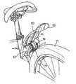
- FIG. 1is an operational perspective view of a generator for a bicycle in accordance with the present invention mounted on the bicycle;
- FIG. 2is an exploded perspective view of the generator for a bicycle in FIG. 1;
- FIG. 3is a partially exploded perspective view of the generator for a bicycle in FIG. 1;
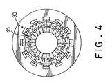
- FIG. 4is a side plan view of the coil and the permanent magnet in FIG. 2;
- FIG. 5is an operational side plan of the generator for a bicycle when the bicycle is in use and the light works.
- a generator for a bicyclein accordance with the present invention comprises around rotor ( 10 ), an annular coil ( 20 ) secured in the rotor ( 10 ) and a stator ( 30 ) rotatably extending through the rotor ( 10 ) and the coil ( 20 ).
- the rotor ( 10 )includes two casings ( 11 , 111 ) abutting each other to form a chamber (not numbered) in the rotor ( 10 ).
- Each of the two casings ( 11 , 111 )includes a first side (not numbered) and a second side.
- the first side of each casing ( 11 , 111 )abuts the first side of the other casing ( 11 , 111 ).
- a recess ( 16 )is centrally defined in the first side of each casing ( 11 , 111 ) to align with the recess in the other casing ( 11 , 111 ).
- a hole ( 12 )is centrally defined in each casing ( 11 , 111 ) to align with the hole ( 12 ) in the other casing ( 11 , 111 ).
- the hole ( 12 )has a diameter smaller than that of the recess ( 16 ) and communicates with the recess ( 16 ).
- the recess ( 16 )includes a bottom having an annular flange ( 13 ) inwardly and radially extending from the bottom of the recess ( 16 ) to form a passage ( 14 ) communicating with the hole ( 12 ) and the recess ( 16 ) so that the passage ( 14 ) has a diameter smaller than that of the hole ( 12 ).
- An indent ( 131 )is defined in the flange ( 13 ) and laterally communicates with the passage ( 14 ).
- Each first side of the casings ( 11 , 111 )has at least one stud ( 15 ) perpendicularly extending from the casing ( 11 , 111 ) and one bore ( 151 ) perpendicularly defined in the casing ( 11 , 111 ) to securely receive a corresponding stud ( 15 ) to connect the two casings ( 11 , 111 ).
- a bearing ( 17 )is securely mounted in the hole ( 12 ) in each casing ( 11 , 111 ) and abuts the annular flange of the casings ( 11 , 111 ).
- the coil ( 20 )comprises two metal covers ( 201 , 202 ), a coil seat (not shown), a winding (not shown) and two inner wires ( 23 ).
- the metal covers ( 201 , 202 )abut each other to enclose a coil seat (not shown) and are soldered to each other.
- the winding (not shown)is wound around the coil seat.
- Each of the metal covers ( 201 , 202 )has multiple salient poles ( 21 , 22 ) perpendicularly extending from the inner periphery of each cover ( 201 , 202 ) parallel to the axis of rotation and abutting the inner periphery of the coil seat, such that each cover ( 201 , 202 ) will securely attach to one side of the coil seat.
- the salient poles ( 21 ) of the metal cover ( 201 )correspond to that of the metal cover ( 202 ).
- the two inner wires ( 23 )are respectively electrically connected to the two metal covers ( 201 , 202 ) and extend respectively into the holes ( 12 ) through the indents ( 141 ).
- One end of each inner wire ( 23 ) extending into the corresponding hole ( 12 )is electrically connected to the outer periphery of a corresponding one of the bearings ( 17 ), such that each bearing ( 17 ) is further used as a collector.
- the stator ( 30 )comprises an insulating shaft ( 32 ), an annular flange ( 31 ) and a ring of permanent magnets ( 35 ).
- the insulating shaft ( 32 )rotatably extends through the coil ( 20 ) and has two opposite ends secured in the bearings ( 17 ) of the rotor ( 10 ).
- the annular flange ( 31 )radially extends outwardly from the middle portion of the shaft ( 32 ).
- the ring of permanent magnets ( 35 )is mounted on the outer periphery of the annular flange ( 31 ).
- the permanent magnets ( 35 )correspond to the salient poles ( 21 , 22 ) in the metal covers ( 201 , 202 ). Further with reference to FIG.
- the magnetic poles of the permanent magnet ( 35 )alternate around the ring of permanent magnets ( 35 ).
- Two protrusions ( 33 )extend respectively from two opposite side of the annular flange ( 31 ) around the shaft ( 32 ) to the middle portions of the bearings ( 17 ).
- An electrical ring connector ( 40 )is mounted on each end of the shaft ( 32 ) and abuts and electrically connects with the middle portion of a corresponding one of the bearings ( 17 ).
- One end of an outer wire ( 41 )is electrically connected to the metal ring ( 40 ), and the other end is adapted to be electrically connected to a light ( 50 ) or an audible device (not shown).
- the light ( 50 ) or the audible devicecan be mounted anywhere on the frame ( 70 ) of the bicycle.
- the light ( 50 )can include multiple lights that can be mounted on the fender ( 60 ), the handlebar ( 73 ) the fork ( 74 ) or, the seat ( 72 ).
- the generator for a bicycle in accordance with the present inventionis mounted on the frame ( 70 ) of the bicycle near one of the wheels ( 71 , 710 ) of the bicycle by an insulating bracket ( 61 ). Accordingly, when the bicycle is in use and the wheels ( 71 , 710 ) rotate, the coil ( 20 ) will rotate with the casings ( 11 , 111 ) relative to the stator ( 30 ). The coil windings will cut through the magnetic line of flux of the permanent magnet ( 35 ) and generate electricity.
- the electricitywill be transmitted to the light or the audible device through the covers ( 201 , 202 ), the inner wires ( 23 ) connected to the metal covers ( 201 , 202 ), the bearings ( 17 ), the electrical ring connectors ( 40 ) and the outer wires ( 41 ) connected to the metal rings ( 40 ) to the light ( 50 ) or the audible device. Consequently, the enjoyment of riding the bicycle is improved.
- the light ( 50 ) or the audible deviceprovides a warning effect to other people at night. The safety of riding the bicycle is also improved.
Landscapes
- Engineering & Computer Science (AREA)
- Power Engineering (AREA)
- Mechanical Engineering (AREA)
- Permanent Magnet Type Synchronous Machine (AREA)
- Lighting Device Outwards From Vehicle And Optical Signal (AREA)
Abstract
Description
1. Field of the Invention
The present invention relates to a generator, and more particularly to a generator for a bicycle light or an audible device.
2. Description of Related Art
To promote bicycle safety when riding a bicycle in the dark, a front light is mounted on a head tube of the bicycle. The power source for the front light is a battery that is mounted on the bicycle. However, the battery needs to be replaced when the battery is exhaust. It is very inconvenient for a rider to exchange the exhausted battery and very dangerous riding in night without lighting device. Consequently, a conventional bicycle generator is provided for supplying power to a lighting device that is mounted on a bicycle. The generators from earlier generations were usually mounted on a rear wheel strut with a geared drive arm in contact with the sidewall of the rear wheel. The drive arm would weaken the wheel sidewall and lead to blowouts. The generator had to be adjusted so that the drive arm made good contact with the wheel sidewall. Because of the gears and linkage between the drive arm and the generator, the generator often had to be repaired or replaced.
The present invention has arisen to mitigate and/or obviate the disadvantages of the conventional power source for the bicycle.
The main objective of the present invention is to provide a simplified generator for a bicycle that is driven by the tread surface of a bicycle tire to generate electricity for a light or an audible device to improve the enjoyment and safety of riding a bicycle.
To achieve the objective, the generator for a bicycle in accordance with the present invention comprises a rotor abutting the tread of a wheel of the bicycle. A coil is mounted in the rotor and electrically connected to two bearings that are mounted on the opposite sides of the rotor by two inner wires. A stator has a shaft extending through the two bearings and a permanent magnet sleeved onto the shaft and corresponding to the coil. Two metal rings are respectively sleeved onto opposite ends of the shaft and electrically connected to the bearings. A light is mounted on the bicycle and electrically connected to the metal rings. The coil will rotate with the rotor relative to the stator when the bicycle is moving and generate electricity that is transmitted to the light, and the light improves the enjoyment and safety of riding the bicycle.
Further benefits and advantages of the present invention will become apparent after a careful reading of the detailed description with appropriate reference to the accompanying drawings.
FIG. 1 is an operational perspective view of a generator for a bicycle in accordance with the present invention mounted on the bicycle;
FIG. 2 is an exploded perspective view of the generator for a bicycle in FIG. 1;
FIG. 3 is a partially exploded perspective view of the generator for a bicycle in FIG. 1;
FIG. 4 is a side plan view of the coil and the permanent magnet in FIG. 2; and
FIG. 5 is an operational side plan of the generator for a bicycle when the bicycle is in use and the light works.
With reference to the drawings and initially to FIGS. 1-3, a generator for a bicycle in accordance with the present invention comprises around rotor (10), an annular coil (20) secured in the rotor (10) and a stator (30) rotatably extending through the rotor (10) and the coil (20).
The rotor (10) includes two casings (11,111) abutting each other to form a chamber (not numbered) in the rotor (10). Each of the two casings (11,111) includes a first side (not numbered) and a second side. The first side of each casing (11,111) abuts the first side of the other casing (11,111). A recess (16) is centrally defined in the first side of each casing (11,111) to align with the recess in the other casing (11,111). A hole (12) is centrally defined in each casing (11,111) to align with the hole (12) in the other casing (11,111). The hole (12) has a diameter smaller than that of the recess (16) and communicates with the recess (16). The recess (16) includes a bottom having an annular flange (13) inwardly and radially extending from the bottom of the recess (16) to form a passage (14) communicating with the hole (12) and the recess (16) so that the passage (14) has a diameter smaller than that of the hole (12). An indent (131) is defined in the flange (13) and laterally communicates with the passage (14). Each first side of the casings (11,111) has at least one stud (15) perpendicularly extending from the casing (11,111) and one bore (151) perpendicularly defined in the casing (11,111) to securely receive a corresponding stud (15) to connect the two casings (11,111). A bearing (17) is securely mounted in the hole (12) in each casing (11,111) and abuts the annular flange of the casings (11,111).
The coil (20) comprises two metal covers (201,202), a coil seat (not shown), a winding (not shown) and two inner wires (23). The metal covers (201,202) abut each other to enclose a coil seat (not shown) and are soldered to each other. The winding (not shown) is wound around the coil seat. Each of the metal covers (201,202) has multiple salient poles (21,22) perpendicularly extending from the inner periphery of each cover (201,202) parallel to the axis of rotation and abutting the inner periphery of the coil seat, such that each cover (201,202) will securely attach to one side of the coil seat. The salient poles (21) of the metal cover (201) correspond to that of the metal cover (202). The two inner wires (23) are respectively electrically connected to the two metal covers (201,202) and extend respectively into the holes (12) through the indents (141). One end of each inner wire (23) extending into the corresponding hole (12) is electrically connected to the outer periphery of a corresponding one of the bearings (17), such that each bearing (17) is further used as a collector.
The stator (30) comprises an insulating shaft (32), an annular flange (31) and a ring of permanent magnets (35). The insulating shaft (32) rotatably extends through the coil (20) and has two opposite ends secured in the bearings (17) of the rotor (10). The annular flange (31) radially extends outwardly from the middle portion of the shaft (32). The ring of permanent magnets (35) is mounted on the outer periphery of the annular flange (31). The permanent magnets (35) correspond to the salient poles (21,22) in the metal covers (201,202). Further with reference to FIG. 4, the magnetic poles of the permanent magnet (35) alternate around the ring of permanent magnets (35). Two protrusions (33) extend respectively from two opposite side of the annular flange (31) around the shaft (32) to the middle portions of the bearings (17).
An electrical ring connector (40) is mounted on each end of the shaft (32) and abuts and electrically connects with the middle portion of a corresponding one of the bearings (17). One end of an outer wire (41) is electrically connected to the metal ring (40), and the other end is adapted to be electrically connected to a light (50) or an audible device (not shown). With reference top FIG. 5, the light (50) or the audible device can be mounted anywhere on the frame (70) of the bicycle. The light (50) can include multiple lights that can be mounted on the fender (60), the handlebar (73) the fork (74) or, the seat (72).
With reference to FIGS. 1 and 5, the generator for a bicycle in accordance with the present invention is mounted on the frame (70) of the bicycle near one of the wheels (71,710) of the bicycle by an insulating bracket (61). Accordingly, when the bicycle is in use and the wheels (71,710) rotate, the coil (20) will rotate with the casings (11,111) relative to the stator (30). The coil windings will cut through the magnetic line of flux of the permanent magnet (35) and generate electricity. The electricity will be transmitted to the light or the audible device through the covers (201,202), the inner wires (23) connected to the metal covers (201,202), the bearings (17), the electrical ring connectors (40) and the outer wires (41) connected to the metal rings (40) to the light (50) or the audible device. Consequently, the enjoyment of riding the bicycle is improved. In addition, the light (50) or the audible device provides a warning effect to other people at night. The safety of riding the bicycle is also improved.
Although the invention has been explained in relation to its preferred embodiment, it is to be understood that many other possible modifications and variations can be made without departing from the spirit and scope of the invention as hereinafter claimed.
Claims (12)
1. A permanent magnet generator for a bicycle light mounted on a bicycle that includes a frame, wheels rotatably mounted on the frame and an insulating bracket attached to the frame, the generator comprising:
a rotor with an axis of rotation adapted to be rotatably mounted on the insulating bracket and adapted to abut against one of the wheels of the bicycle, the rotor including:
two casings each having a first side abutting each other to form a chamber in the rotor and a second side opposite to each other;
a hole with a diameter and an inner periphery centrally defined in the second side of each casing to securely mount a bearing with an outer periphery and a middle portion in the rotor;
a recess with an inner periphery centrally defined in the first side of each casing and having a diameter greater than that of the hole; and
an indent defined in the inner periphery of each recess;
an annular coil securely mounted in the chamber in the rotor, the annular coil including:
two metal covers abutting each other and soldered to enclose a coil seat and a winding wound around the coil seat;
multiple salient poles situated in an inner periphery of each cover and parallel to the axis of rotation; and
two inner wires electrically connected respectively to the covers and extending through the indents in the casings to electrically connect respectively to the outer peripheries of the bearings;
a stator rotatably extending through the rotor and the coil, the stator including:
a shaft made of insulating material, rotatably extending through the coil, having two opposite ends respectively secured in the bearings and a middle portion and partially extending out of the bearings and mounted in the insulating bracket of the bicycle for mounting the rotor on the bicycle;
an annular flange radially extending outwardly from the middle portion of the shaft and having an outer periphery; and
a ring of permanent magnets mounted on the outer periphery of the annular flange and corresponding to the salient poles of the coil;
two electrical rings respectively mounted around the ends of the shaft and electrically connected to the middle portions of the bearings; and
two outer wires each having a first end electrically attached to one of the electrical rings and a second end attached to the bicycle light;
wherein the coil rotates with the casings relative to the stator when the bicycle is in use and generates electricity that is transmitted to the light to operate the light.
2. The generator for a bicycle as claimed inclaim 1 , wherein the recess in each casing comprises a bottom having an annular flange inwardly and radially extending from the bottom of the recess to stop the corresponding one of the bearings and form a passage communicating with the hole and the recess, and the indent is defined in the annular flange.
3. The generator for a bicycle as claimed inclaim 1 , wherein each casing comprises at least one stud perpendicularly extending from the first side and at least one bore defined in the first side to securely receive a corresponding stud extending from the first side of the other casing.
4. The generator for a bicycle as claimed inclaim 1 , wherein the stator comprises two protrusions extending respectively from two opposite sides of the annular flange of the stator to abut the middle portions of the bearings.
5. The generator for a bicycle as claimed inclaim 2 , wherein each casing comprises at least one stud perpendicularly extending from the first side and at least one bore defined in the first side to securely receive a corresponding stud.
6. The generator for a bicycle as claimed inclaim 2 , wherein the stator comprises a protrusion extending from two opposite sides of the annular flange of the stator and to abut the middle portion of the bearing.
7. The generator for a bicycle as claimed inclaim 3 , wherein the stator comprises two protrusions respectively extending from two opposite sides of the annular flange of the stator to abut the middle portions of the bearings.
8. The generator for a bicycle as claimed inclaim 4 , wherein the permanent magnets have magnetic poles that alternate around the permanent magnets.
9. The generator for a bicycle as claimed inclaim 5 , wherein the stator comprises two protrusions extending respectively from two opposite sides of the annular flange of the stator to abut the middle portions of the bearings.
10. The generator for a bicycle as claimed inclaim 6 , wherein the permanent magnets have magnetic poles that alternate around the permanent magnets.
11. The generator for a bicycle as claimed inclaim 7 , wherein the permanent magnets have magnetic poles that alternate around the permanent magnets.
12. The generator for a bicycle as claimed inclaim 9 , wherein the permanent magnets have magnetic poles that alternate around the permanent magnets.
Priority Applications (2)
| Application Number | Priority Date | Filing Date | Title |
|---|---|---|---|
| US09/977,964US6703716B2 (en) | 2001-10-17 | 2001-10-17 | Permanent magnet generator for bicycle light operation |
| CN02241000UCN2582969Y (en) | 2001-10-17 | 2002-07-02 | Light generating device for bicycle |
Applications Claiming Priority (1)
| Application Number | Priority Date | Filing Date | Title |
|---|---|---|---|
| US09/977,964US6703716B2 (en) | 2001-10-17 | 2001-10-17 | Permanent magnet generator for bicycle light operation |
Publications (2)
| Publication Number | Publication Date |
|---|---|
| US20030071464A1 US20030071464A1 (en) | 2003-04-17 |
| US6703716B2true US6703716B2 (en) | 2004-03-09 |
Family
ID=25525687
Family Applications (1)
| Application Number | Title | Priority Date | Filing Date |
|---|---|---|---|
| US09/977,964Expired - Fee RelatedUS6703716B2 (en) | 2001-10-17 | 2001-10-17 | Permanent magnet generator for bicycle light operation |
Country Status (2)
| Country | Link |
|---|---|
| US (1) | US6703716B2 (en) |
| CN (1) | CN2582969Y (en) |
Cited By (27)
| Publication number | Priority date | Publication date | Assignee | Title |
|---|---|---|---|---|
| US6774503B1 (en)* | 2003-11-07 | 2004-08-10 | Far Great Plastics Industrial Co., Ltd. | Wheel having an accelerating electricity charging device |
| US6833642B1 (en)* | 2003-12-17 | 2004-12-21 | Hung Pao-Chuang | Automatic electric power generating device for wheels |
| US6987327B1 (en)* | 2003-07-21 | 2006-01-17 | Gerardo Ramos Lucatero | Electric generating convertible bicycle |
| US20070013244A1 (en)* | 2005-07-12 | 2007-01-18 | Kinkaid Christopher P | Friction drive electrical power converter apparatus and process |
| US20070052200A1 (en)* | 2004-10-05 | 2007-03-08 | Ktech Enterprises, Inc. | Lighting System for a Bicycle |
| US20070090703A1 (en)* | 2005-10-24 | 2007-04-26 | Ming-Hsiang Yeh | Shock-absorable electricity-producing apparatus |
| US7311164B1 (en)* | 2005-10-07 | 2007-12-25 | Kertes Jon P | Illuminated scooter |
| US20090268479A1 (en)* | 2007-10-09 | 2009-10-29 | Doug Lunde | Lighted Bicycle Pedal |
| US20100090475A1 (en)* | 2008-10-09 | 2010-04-15 | Wen-Bin Tsai | Exercise Device Capable Of Generating Electricity |
| US20110074563A1 (en)* | 2009-09-30 | 2011-03-31 | Industrial Technology Research Institute | Swinging device and apparatus for detecting rotating status and information displaying device using the same |
| US20120305345A1 (en)* | 2010-04-16 | 2012-12-06 | Ward Gregory A | Portable Antiskid Brake System |
| US20140042752A1 (en)* | 2012-08-09 | 2014-02-13 | Marcus McDermott | Method and system to generate electricity |
| US20140133171A1 (en)* | 2011-04-21 | 2014-05-15 | Soon Chang Kwon | Light emitting wheel hub |
| CN105034685A (en)* | 2015-07-29 | 2015-11-11 | 平湖市双喜童车制造有限公司 | Luminous wheel for children bicycle |
| CN106942870A (en)* | 2017-05-17 | 2017-07-14 | 邓冠山 | A kind of case wheel generated electricity |
| US11289974B2 (en)* | 2019-06-07 | 2022-03-29 | Anthony Macaluso | Power generation from vehicle wheel rotation |
| US11299054B2 (en) | 2019-06-07 | 2022-04-12 | Anthony Macaluso | Methods and apparatus for powering a vehicle |
| US11432123B2 (en) | 2019-06-07 | 2022-08-30 | Anthony Macaluso | Systems and methods for managing a vehicle's energy via a wireless network |
| US11472306B1 (en) | 2022-03-09 | 2022-10-18 | Anthony Macaluso | Electric vehicle charging station |
| US11577606B1 (en) | 2022-03-09 | 2023-02-14 | Anthony Macaluso | Flexible arm generator |
| US11587740B2 (en) | 2019-06-07 | 2023-02-21 | Anthony Macaluso | Methods, systems and apparatus for powering a vehicle |
| US11641572B2 (en) | 2019-06-07 | 2023-05-02 | Anthony Macaluso | Systems and methods for managing a vehicle's energy via a wireless network |
| US11837411B2 (en) | 2021-03-22 | 2023-12-05 | Anthony Macaluso | Hypercapacitor switch for controlling energy flow between energy storage devices |
| US11955875B1 (en) | 2023-02-28 | 2024-04-09 | Anthony Macaluso | Vehicle energy generation system |
| US12107455B2 (en) | 2023-01-30 | 2024-10-01 | Anthony Macaluso | Matable energy storage devices |
| US12407219B2 (en) | 2023-02-28 | 2025-09-02 | Anthony Macaluso | Vehicle energy generation system |
| US12412430B2 (en) | 2023-12-22 | 2025-09-09 | Anthony Macaluso | Systems and methods for managing a vehicle's energy via a wireless network |
Families Citing this family (9)
| Publication number | Priority date | Publication date | Assignee | Title |
|---|---|---|---|---|
| US7159497B2 (en)* | 2002-01-25 | 2007-01-09 | Eastway Fair Company Ltd. | Light beam alignment system |
| CN102211632B (en)* | 2010-04-07 | 2013-02-13 | 彭德右 | Wheel drive and power generation structure |
| DK2447145T3 (en)* | 2010-10-29 | 2014-04-07 | Guenther Hirn | Electric drive system for a bicycle |
| US20120249316A1 (en)* | 2011-04-01 | 2012-10-04 | Lite-On Technology Corporation | Bicycle brake light system |
| CN202179824U (en)* | 2011-07-22 | 2012-04-04 | 北京美亚视景创恒科技有限公司 | Digital body-building equipment cluster system |
| DE102016108269A1 (en)* | 2016-05-04 | 2017-11-09 | Volkswagen Aktiengesellschaft | Connecting device for contacting at least two circuits of an electrical machine |
| CN106828756B (en)* | 2016-12-29 | 2018-11-23 | 广州市鑫堡自行车有限公司 | A kind of electric bicycle carrying electricity generation module |
| CN106828719B (en)* | 2016-12-29 | 2018-11-06 | 台州市皓仔邦工业设计有限公司 | A kind of electric bicycle with body-building power generation function |
| CN108203039A (en)* | 2018-02-02 | 2018-06-26 | 住友富士电梯有限公司 | The rolling guide shoe of magnetic energy electricity generation and the elevator containing the rolling guide shoe |
Citations (36)
| Publication number | Priority date | Publication date | Assignee | Title |
|---|---|---|---|---|
| US3573519A (en)* | 1969-04-03 | 1971-04-06 | Nippon Denso Co | Rotors for alternators |
| US4191988A (en)* | 1977-12-27 | 1980-03-04 | Shokichi Kumakura | Identification lamp apparatus |
| US4364448A (en)* | 1978-07-20 | 1982-12-21 | Yamaha Hatsudoki Kabushiki Kaisha | Speed control for wheeled vehicles |
| US4559462A (en)* | 1984-05-30 | 1985-12-17 | Hernandez Badillo Wilfredo | Dynamo-electric cycle axle |
| US4636670A (en)* | 1983-05-04 | 1987-01-13 | Ingvar Nilsson Mekaniska Ab | Control gear for a dynamo connected to a hub |
| US4677328A (en)* | 1984-11-08 | 1987-06-30 | Rikichi Kumakura | Generator for use on bicycle |
| US4860176A (en)* | 1986-03-13 | 1989-08-22 | Frank Bauwens | Lighting device for vehicle |
| US4893877A (en)* | 1988-08-23 | 1990-01-16 | Manual Powell | Self-generated lighted hubcab |
| US4924125A (en)* | 1987-09-15 | 1990-05-08 | Clark Automotive Developments Limited | Electric motor or alternator |
| US5115159A (en)* | 1989-10-25 | 1992-05-19 | Bridgestone Cycle Co., Ltd. | Built-in generator for bicycle |
| US5268602A (en)* | 1991-08-20 | 1993-12-07 | Vereinigte Drahtwerke A.G. | Electric machine, especially a dynamo for mounting on a wheel hub |
| JPH07246967A (en)* | 1994-03-08 | 1995-09-26 | Aai:Kk | Power generator for bicycle |
| US5461269A (en)* | 1994-10-27 | 1995-10-24 | De Raucourt; Jean-Claude | Lighting generator for bicycle |
| US5505277A (en)* | 1993-07-23 | 1996-04-09 | Yamaha Hatsudoki Kabushiki Kaisha | Control for electric assist vehicle |
| US5584561A (en)* | 1994-08-25 | 1996-12-17 | Leader Industries, Inc. | Lighting device for a bicycle |
| US5602448A (en)* | 1993-09-14 | 1997-02-11 | Kabushiki Kaisha Riken | Electric powered bicycle |
| US5606207A (en)* | 1995-04-11 | 1997-02-25 | Gotoh; Kazuhiko | Power generating apparatus for a bicycle |
| EP0778654A2 (en)* | 1995-12-07 | 1997-06-11 | FER Fahrzeugelektrik GmbH | Three-phase generator for bicycles |
| GB2314213A (en)* | 1996-06-12 | 1997-12-17 | Kook Kim Youn | Cycle hub generator, control arrangement and condenser backup supply |
| US5842535A (en)* | 1996-02-02 | 1998-12-01 | Electric Transportation Company, Llc | Electric drive assembly for bicycles |
| US5857762A (en)* | 1994-01-11 | 1999-01-12 | Schwaller; Edwin | Bicycle lighting system and generator |
| US5874792A (en)* | 1997-06-10 | 1999-02-23 | Industrial Technology Research Institute | Bicycle generator |
| JPH1198797A (en)* | 1997-09-19 | 1999-04-09 | Toyo Electric Mfg Co Ltd | Generator for bicycle |
| US5895991A (en)* | 1997-05-15 | 1999-04-20 | Sram Deutschland Gmbh | Electric generator for bicycles |
| US5992553A (en)* | 1997-01-13 | 1999-11-30 | Morrison; Thomas R. | Pedal power sensor and human powered vehicle drive augmentation responsive to cyclic pedal power input |
| US6002187A (en)* | 1996-07-22 | 1999-12-14 | Pioneer Precision Machinery Corporation | Bicycle electricity generator and a method of attaching the electricity generator to a bicycle |
| JP2000069731A (en)* | 1998-08-21 | 2000-03-03 | Shimano Inc | Claw-pole generator and bicycle |
| US6118196A (en)* | 1998-03-26 | 2000-09-12 | Shing Chyoo Attend Industry Co., Ltd. | Electrical generator attached to a bicycle wheel |
| US6320336B1 (en)* | 1998-10-12 | 2001-11-20 | Sony Corporation | Bicycle with power assisting function |
| EP1155948A2 (en)* | 2000-05-17 | 2001-11-21 | Sanyo Electric Co., Ltd. | Bicycle hub dynamo and bicycle |
| US6398395B1 (en)* | 1999-08-10 | 2002-06-04 | Teltek Co., Ltd. | Compact generator, light-emitting wheel having the same, and manufacturing method therefor |
| US6486582B1 (en)* | 1997-11-21 | 2002-11-26 | Micronasa Di Patarchi Alberto | Dynamo-electric machine rotating by electromagnetic induction such as it acts in linear electric motors |
| US6559564B1 (en)* | 2000-01-31 | 2003-05-06 | Shimano, Inc. | Bicycle hub with generator and antilock functions |
| US6588528B2 (en)* | 2001-08-01 | 2003-07-08 | Electric Transportation Company | Electric vehicle drive system |
| US6588913B1 (en)* | 2002-02-28 | 2003-07-08 | Kuo-Lin Huang | Flashing light-emitting device with a wind generator |
| US6605884B2 (en)* | 2001-06-07 | 2003-08-12 | Shimano, Inc. | Bicycle hub axle having a dynamo thereon |
- 2001
- 2001-10-17USUS09/977,964patent/US6703716B2/ennot_activeExpired - Fee Related
- 2002
- 2002-07-02CNCN02241000Upatent/CN2582969Y/ennot_activeExpired - Fee Related
Patent Citations (39)
| Publication number | Priority date | Publication date | Assignee | Title |
|---|---|---|---|---|
| US3573519A (en)* | 1969-04-03 | 1971-04-06 | Nippon Denso Co | Rotors for alternators |
| US4191988A (en)* | 1977-12-27 | 1980-03-04 | Shokichi Kumakura | Identification lamp apparatus |
| US4364448A (en)* | 1978-07-20 | 1982-12-21 | Yamaha Hatsudoki Kabushiki Kaisha | Speed control for wheeled vehicles |
| US4636670A (en)* | 1983-05-04 | 1987-01-13 | Ingvar Nilsson Mekaniska Ab | Control gear for a dynamo connected to a hub |
| US4559462A (en)* | 1984-05-30 | 1985-12-17 | Hernandez Badillo Wilfredo | Dynamo-electric cycle axle |
| US4677328A (en)* | 1984-11-08 | 1987-06-30 | Rikichi Kumakura | Generator for use on bicycle |
| US4860176A (en)* | 1986-03-13 | 1989-08-22 | Frank Bauwens | Lighting device for vehicle |
| US4924125A (en)* | 1987-09-15 | 1990-05-08 | Clark Automotive Developments Limited | Electric motor or alternator |
| US4893877A (en)* | 1988-08-23 | 1990-01-16 | Manual Powell | Self-generated lighted hubcab |
| US5115159A (en)* | 1989-10-25 | 1992-05-19 | Bridgestone Cycle Co., Ltd. | Built-in generator for bicycle |
| US5268602A (en)* | 1991-08-20 | 1993-12-07 | Vereinigte Drahtwerke A.G. | Electric machine, especially a dynamo for mounting on a wheel hub |
| US5505277A (en)* | 1993-07-23 | 1996-04-09 | Yamaha Hatsudoki Kabushiki Kaisha | Control for electric assist vehicle |
| US5602448A (en)* | 1993-09-14 | 1997-02-11 | Kabushiki Kaisha Riken | Electric powered bicycle |
| US5603388A (en)* | 1993-09-14 | 1997-02-18 | Kabushiki Kaisha Riken | Electric powered bicycle |
| US5857762A (en)* | 1994-01-11 | 1999-01-12 | Schwaller; Edwin | Bicycle lighting system and generator |
| JPH07246967A (en)* | 1994-03-08 | 1995-09-26 | Aai:Kk | Power generator for bicycle |
| US5584561A (en)* | 1994-08-25 | 1996-12-17 | Leader Industries, Inc. | Lighting device for a bicycle |
| US5461269A (en)* | 1994-10-27 | 1995-10-24 | De Raucourt; Jean-Claude | Lighting generator for bicycle |
| US5606207A (en)* | 1995-04-11 | 1997-02-25 | Gotoh; Kazuhiko | Power generating apparatus for a bicycle |
| EP0778654A2 (en)* | 1995-12-07 | 1997-06-11 | FER Fahrzeugelektrik GmbH | Three-phase generator for bicycles |
| US5932943A (en)* | 1995-12-07 | 1999-08-03 | Fer Fahrzeugeletrik Gmbh | Bicycle dynamo having a rotary-current generator |
| US5842535A (en)* | 1996-02-02 | 1998-12-01 | Electric Transportation Company, Llc | Electric drive assembly for bicycles |
| GB2314213A (en)* | 1996-06-12 | 1997-12-17 | Kook Kim Youn | Cycle hub generator, control arrangement and condenser backup supply |
| US6002187A (en)* | 1996-07-22 | 1999-12-14 | Pioneer Precision Machinery Corporation | Bicycle electricity generator and a method of attaching the electricity generator to a bicycle |
| US5992553A (en)* | 1997-01-13 | 1999-11-30 | Morrison; Thomas R. | Pedal power sensor and human powered vehicle drive augmentation responsive to cyclic pedal power input |
| US5895991A (en)* | 1997-05-15 | 1999-04-20 | Sram Deutschland Gmbh | Electric generator for bicycles |
| US5874792A (en)* | 1997-06-10 | 1999-02-23 | Industrial Technology Research Institute | Bicycle generator |
| JPH1198797A (en)* | 1997-09-19 | 1999-04-09 | Toyo Electric Mfg Co Ltd | Generator for bicycle |
| US6486582B1 (en)* | 1997-11-21 | 2002-11-26 | Micronasa Di Patarchi Alberto | Dynamo-electric machine rotating by electromagnetic induction such as it acts in linear electric motors |
| US6118196A (en)* | 1998-03-26 | 2000-09-12 | Shing Chyoo Attend Industry Co., Ltd. | Electrical generator attached to a bicycle wheel |
| JP2000069731A (en)* | 1998-08-21 | 2000-03-03 | Shimano Inc | Claw-pole generator and bicycle |
| US6409197B1 (en)* | 1998-08-21 | 2002-06-25 | Shimano, Inc. | Claw-pole dynamo and bicycle |
| US6320336B1 (en)* | 1998-10-12 | 2001-11-20 | Sony Corporation | Bicycle with power assisting function |
| US6398395B1 (en)* | 1999-08-10 | 2002-06-04 | Teltek Co., Ltd. | Compact generator, light-emitting wheel having the same, and manufacturing method therefor |
| US6559564B1 (en)* | 2000-01-31 | 2003-05-06 | Shimano, Inc. | Bicycle hub with generator and antilock functions |
| EP1155948A2 (en)* | 2000-05-17 | 2001-11-21 | Sanyo Electric Co., Ltd. | Bicycle hub dynamo and bicycle |
| US6605884B2 (en)* | 2001-06-07 | 2003-08-12 | Shimano, Inc. | Bicycle hub axle having a dynamo thereon |
| US6588528B2 (en)* | 2001-08-01 | 2003-07-08 | Electric Transportation Company | Electric vehicle drive system |
| US6588913B1 (en)* | 2002-02-28 | 2003-07-08 | Kuo-Lin Huang | Flashing light-emitting device with a wind generator |
Cited By (70)
| Publication number | Priority date | Publication date | Assignee | Title |
|---|---|---|---|---|
| US6987327B1 (en)* | 2003-07-21 | 2006-01-17 | Gerardo Ramos Lucatero | Electric generating convertible bicycle |
| US6774503B1 (en)* | 2003-11-07 | 2004-08-10 | Far Great Plastics Industrial Co., Ltd. | Wheel having an accelerating electricity charging device |
| US6833642B1 (en)* | 2003-12-17 | 2004-12-21 | Hung Pao-Chuang | Automatic electric power generating device for wheels |
| US20070052200A1 (en)* | 2004-10-05 | 2007-03-08 | Ktech Enterprises, Inc. | Lighting System for a Bicycle |
| US20070013244A1 (en)* | 2005-07-12 | 2007-01-18 | Kinkaid Christopher P | Friction drive electrical power converter apparatus and process |
| US7311164B1 (en)* | 2005-10-07 | 2007-12-25 | Kertes Jon P | Illuminated scooter |
| US20070090703A1 (en)* | 2005-10-24 | 2007-04-26 | Ming-Hsiang Yeh | Shock-absorable electricity-producing apparatus |
| US7408266B2 (en)* | 2005-10-24 | 2008-08-05 | Ming-Hsiang Yeh | Shock-absorbable electricity-producing apparatus |
| US8132945B2 (en) | 2007-10-09 | 2012-03-13 | Doug Lunde | Lighted bicycle pedal |
| US20090268479A1 (en)* | 2007-10-09 | 2009-10-29 | Doug Lunde | Lighted Bicycle Pedal |
| US20100090475A1 (en)* | 2008-10-09 | 2010-04-15 | Wen-Bin Tsai | Exercise Device Capable Of Generating Electricity |
| US20110074563A1 (en)* | 2009-09-30 | 2011-03-31 | Industrial Technology Research Institute | Swinging device and apparatus for detecting rotating status and information displaying device using the same |
| US8223003B2 (en) | 2009-09-30 | 2012-07-17 | Industrial Technology Research Institute | Swinging device and apparatus for detecting rotating status and information displaying device using the same |
| US20120305345A1 (en)* | 2010-04-16 | 2012-12-06 | Ward Gregory A | Portable Antiskid Brake System |
| US9446748B2 (en)* | 2010-04-16 | 2016-09-20 | Gregory A Ward | Portable antilock brake system |
| US20140133171A1 (en)* | 2011-04-21 | 2014-05-15 | Soon Chang Kwon | Light emitting wheel hub |
| US9073479B2 (en)* | 2011-04-21 | 2015-07-07 | Soon Chang Kwon | Light emitting wheel hub |
| US20140042752A1 (en)* | 2012-08-09 | 2014-02-13 | Marcus McDermott | Method and system to generate electricity |
| CN105034685A (en)* | 2015-07-29 | 2015-11-11 | 平湖市双喜童车制造有限公司 | Luminous wheel for children bicycle |
| CN106942870A (en)* | 2017-05-17 | 2017-07-14 | 邓冠山 | A kind of case wheel generated electricity |
| US11626775B2 (en) | 2019-06-07 | 2023-04-11 | Anthony Macaluso | Power generation from vehicle wheel rotation |
| US11904708B2 (en) | 2019-06-07 | 2024-02-20 | Anthony Macaluso | Methods, systems and apparatus for powering a vehicle |
| US11318856B2 (en) | 2019-06-07 | 2022-05-03 | Anthony Macaluso | Methods and apparatus for powering a vehicle |
| US20220209624A1 (en)* | 2019-06-07 | 2022-06-30 | Anthony Macaluso | Power generation from vehicle wheel rotation |
| US11432123B2 (en) | 2019-06-07 | 2022-08-30 | Anthony Macaluso | Systems and methods for managing a vehicle's energy via a wireless network |
| US11431225B2 (en)* | 2019-06-07 | 2022-08-30 | Anthony Macaluso | Power generation from vehicle wheel rotation |
| US11458853B2 (en) | 2019-06-07 | 2022-10-04 | Anthony Macaluso | Methods and apparatus for powering a vehicle |
| US12434570B2 (en) | 2019-06-07 | 2025-10-07 | Anthony Macaluso | Methods, systems and apparatus for powering a vehicle |
| US11548399B1 (en) | 2019-06-07 | 2023-01-10 | Anthony Macaluso | Methods and apparatus for powering a vehicle |
| US12420647B2 (en) | 2019-06-07 | 2025-09-23 | Anthony Macaluso | Methods, systems and apparatus for powering a vehicle |
| US11587740B2 (en) | 2019-06-07 | 2023-02-21 | Anthony Macaluso | Methods, systems and apparatus for powering a vehicle |
| US11615923B2 (en) | 2019-06-07 | 2023-03-28 | Anthony Macaluso | Methods, systems and apparatus for powering a vehicle |
| US12409747B2 (en) | 2019-06-07 | 2025-09-09 | Anthony Macaluso | Methods and apparatus for powering a vehicle |
| US11627449B2 (en) | 2019-06-07 | 2023-04-11 | Anthony Macaluso | Systems and methods for managing a vehicle's energy via a wireless network |
| US11289974B2 (en)* | 2019-06-07 | 2022-03-29 | Anthony Macaluso | Power generation from vehicle wheel rotation |
| US12377734B2 (en) | 2019-06-07 | 2025-08-05 | Anthony Macaluso | Methods, systems and apparatus for powering a vehicle |
| US11641572B2 (en) | 2019-06-07 | 2023-05-02 | Anthony Macaluso | Systems and methods for managing a vehicle's energy via a wireless network |
| US11685276B2 (en) | 2019-06-07 | 2023-06-27 | Anthony Macaluso | Methods and apparatus for powering a vehicle |
| US11722869B2 (en) | 2019-06-07 | 2023-08-08 | Anthony Macaluso | Systems and methods for managing a vehicle's energy via a wireless network |
| US12249896B2 (en)* | 2019-06-07 | 2025-03-11 | Anthony Macaluso | Power generation from vehicle wheel rotation |
| US11757332B2 (en) | 2019-06-07 | 2023-09-12 | Anthony Macaluso | Power generation from vehicle wheel rotation |
| US11785433B2 (en) | 2019-06-07 | 2023-10-10 | Anthony Macaluso | Systems and methods for managing a vehicle’s energy via a wireless network |
| US12103416B2 (en) | 2019-06-07 | 2024-10-01 | Anthony Macaluso | Energy management system and methods |
| US12096324B2 (en) | 2019-06-07 | 2024-09-17 | Anthony Macaluso | Systems and methods for managing a vehicle's energy via a wireless network |
| US11999250B2 (en) | 2019-06-07 | 2024-06-04 | Anthony Macaluso | Methods and apparatus for powering a vehicle |
| US11299054B2 (en) | 2019-06-07 | 2022-04-12 | Anthony Macaluso | Methods and apparatus for powering a vehicle |
| US11916466B2 (en) | 2019-06-07 | 2024-02-27 | Anthony Macaluso | Power generation from vehicle wheel rotation |
| US11919413B2 (en) | 2019-06-07 | 2024-03-05 | Anthony Macaluso | Methods and apparatus for powering a vehicle |
| US11919412B2 (en) | 2019-06-07 | 2024-03-05 | Anthony Macaluso | Methods and apparatus for powering a vehicle |
| US20240178722A1 (en)* | 2019-06-07 | 2024-05-30 | Anthony Macaluso | Power generation from vehicle wheel rotation |
| US11985579B2 (en) | 2019-06-07 | 2024-05-14 | Anthony Macaluso | Systems and methods for managing a vehicle's energy via a wireless network |
| US11970073B2 (en) | 2019-06-07 | 2024-04-30 | Anthony Macaluso | Vehicle energy generation with flywheel |
| US11837411B2 (en) | 2021-03-22 | 2023-12-05 | Anthony Macaluso | Hypercapacitor switch for controlling energy flow between energy storage devices |
| US12157366B2 (en) | 2022-03-09 | 2024-12-03 | Anthony Macaluso | Flexible arm generator |
| US11628724B1 (en) | 2022-03-09 | 2023-04-18 | Anthony Macaluso | Flexible arm generator |
| US11897355B2 (en) | 2022-03-09 | 2024-02-13 | Anthony Macaluso | Electric vehicle charging station |
| US12090844B2 (en) | 2022-03-09 | 2024-09-17 | Anthony Macaluso | Flexible arm generator |
| US11850963B2 (en) | 2022-03-09 | 2023-12-26 | Anthony Macaluso | Electric vehicle charging station |
| US12252026B2 (en) | 2022-03-09 | 2025-03-18 | Anthony Macaluso | Electric vehicle charging station |
| US11919387B1 (en) | 2022-03-09 | 2024-03-05 | Anthony Macaluso | Flexible arm generator |
| US11472306B1 (en) | 2022-03-09 | 2022-10-18 | Anthony Macaluso | Electric vehicle charging station |
| US11577606B1 (en) | 2022-03-09 | 2023-02-14 | Anthony Macaluso | Flexible arm generator |
| US11738641B1 (en) | 2022-03-09 | 2023-08-29 | Anthony Macaluso | Flexible arm generator |
| US11618332B1 (en) | 2022-03-09 | 2023-04-04 | Anthony Macaluso | Electric vehicle charging station |
| US12107455B2 (en) | 2023-01-30 | 2024-10-01 | Anthony Macaluso | Matable energy storage devices |
| US12160132B2 (en) | 2023-01-30 | 2024-12-03 | Anthony Macaluso | Matable energy storage devices |
| US12407219B2 (en) | 2023-02-28 | 2025-09-02 | Anthony Macaluso | Vehicle energy generation system |
| US12003167B1 (en) | 2023-02-28 | 2024-06-04 | Anthony Macaluso | Vehicle energy generation system |
| US11955875B1 (en) | 2023-02-28 | 2024-04-09 | Anthony Macaluso | Vehicle energy generation system |
| US12412430B2 (en) | 2023-12-22 | 2025-09-09 | Anthony Macaluso | Systems and methods for managing a vehicle's energy via a wireless network |
Also Published As
| Publication number | Publication date |
|---|---|
| US20030071464A1 (en) | 2003-04-17 |
| CN2582969Y (en) | 2003-10-29 |
Similar Documents
| Publication | Publication Date | Title |
|---|---|---|
| US6703716B2 (en) | Permanent magnet generator for bicycle light operation | |
| AU753928B2 (en) | Improved compact generator, light-emitting wheel having the same, and manufacturing method therefor | |
| US6565242B2 (en) | Wheel with sound and light effects | |
| US6278216B1 (en) | Vehicle motor | |
| US6605884B2 (en) | Bicycle hub axle having a dynamo thereon | |
| US20110259658A1 (en) | Power output device for wheeled vehicle | |
| EP1491433B1 (en) | Bicycle front end arrangement forming electric power supply system | |
| JPS63502652A (en) | Vehicle lighting system | |
| US6396178B1 (en) | Wheel with a generator | |
| US6749321B2 (en) | Automatic power-generating device for decorative lamps | |
| US10625819B2 (en) | Construction of motorized wheel for vehicle motorization | |
| JP4111966B2 (en) | Bicycle dynamo and bicycle lighting device equipped with the bicycle dynamo | |
| JP4582969B2 (en) | Bicycle hub dynamo | |
| JP3530289B2 (en) | Bicycle generator | |
| WO2002018198A1 (en) | Generator of two-wheeled vehicle and lighting system thereby | |
| US20080007145A1 (en) | Bicycle with at least one generator | |
| US20090010016A1 (en) | Vehicle lighting device | |
| KR101239193B1 (en) | Bicycle bottom bracket capable of power generation | |
| CN200994099Y (en) | Improvement of Bicycle Generator Structure | |
| GB2370923A (en) | Wheel with a generator | |
| JP2001088759A (en) | Hub dynamo for bicycle | |
| CN201224448Y (en) | Wind power self-luminescence tail lamp of bicycle | |
| JPWO2004015842A1 (en) | Rotating electric machine | |
| JP3668068B2 (en) | Bicycle hub dynamo | |
| JPH07291166A (en) | Dynamo for bicycle |
Legal Events
| Date | Code | Title | Description |
|---|---|---|---|
| AS | Assignment | Owner name:LIU, MENG-YU, TAIWAN Free format text:ASSIGNMENT OF ASSIGNORS INTEREST;ASSIGNOR:CHIU, CHUN-CHEN;REEL/FRAME:012265/0217 Effective date:20011012 | |
| REMI | Maintenance fee reminder mailed | ||
| LAPS | Lapse for failure to pay maintenance fees | ||
| STCH | Information on status: patent discontinuation | Free format text:PATENT EXPIRED DUE TO NONPAYMENT OF MAINTENANCE FEES UNDER 37 CFR 1.362 | |
| FP | Lapsed due to failure to pay maintenance fee | Effective date:20080309 |