US6702832B2 - Medical device for cutting a cornea that has a vacuum ring with a slitted vacuum opening - Google Patents
Medical device for cutting a cornea that has a vacuum ring with a slitted vacuum openingDownload PDFInfo
- Publication number
- US6702832B2 US6702832B2US10/272,567US27256702AUS6702832B2US 6702832 B2US6702832 B2US 6702832B2US 27256702 AUS27256702 AUS 27256702AUS 6702832 B2US6702832 B2US 6702832B2
- Authority
- US
- United States
- Prior art keywords
- ring
- head
- blade
- cornea
- vacuum
- Prior art date
- Legal status (The legal status is an assumption and is not a legal conclusion. Google has not performed a legal analysis and makes no representation as to the accuracy of the status listed.)
- Expired - Lifetime
Links
- 210000004087corneaAnatomy0.000titleclaimsabstractdescription41
- 238000005520cutting processMethods0.000titleclaimsdescription9
- 210000003128headAnatomy0.000claimsabstractdescription73
- 238000000034methodMethods0.000claimsdescription8
- 239000012530fluidSubstances0.000claimsdescription5
- 238000004891communicationMethods0.000claimsdescription4
- 230000014759maintenance of locationEffects0.000abstractdescription3
- 230000007246mechanismEffects0.000description16
- 210000002105tongueAnatomy0.000description16
- NJPPVKZQTLUDBO-UHFFFAOYSA-NnovaluronChemical compoundC1=C(Cl)C(OC(F)(F)C(OC(F)(F)F)F)=CC=C1NC(=O)NC(=O)C1=C(F)C=CC=C1FNJPPVKZQTLUDBO-UHFFFAOYSA-N0.000description4
- 210000000744eyelidAnatomy0.000description3
- 238000007142ring opening reactionMethods0.000description3
- 230000005540biological transmissionEffects0.000description2
- 230000008859changeEffects0.000description2
- 230000000994depressogenic effectEffects0.000description2
- 210000000720eyelashAnatomy0.000description2
- 239000000463materialSubstances0.000description2
- 230000009467reductionEffects0.000description2
- 241000446313LamellaSpecies0.000description1
- 230000009471actionEffects0.000description1
- 238000010276constructionMethods0.000description1
- 238000011109contaminationMethods0.000description1
- 238000013016dampingMethods0.000description1
- 230000000881depressing effectEffects0.000description1
- 230000000694effectsEffects0.000description1
- 230000003028elevating effectEffects0.000description1
- 238000000608laser ablationMethods0.000description1
- 238000012986modificationMethods0.000description1
- 230000004048modificationEffects0.000description1
- 230000008569processEffects0.000description1
- 230000005236sound signalEffects0.000description1
- 238000001356surgical procedureMethods0.000description1
- 238000011144upstream manufacturingMethods0.000description1
Images


Classifications
- A—HUMAN NECESSITIES
- A61—MEDICAL OR VETERINARY SCIENCE; HYGIENE
- A61F—FILTERS IMPLANTABLE INTO BLOOD VESSELS; PROSTHESES; DEVICES PROVIDING PATENCY TO, OR PREVENTING COLLAPSING OF, TUBULAR STRUCTURES OF THE BODY, e.g. STENTS; ORTHOPAEDIC, NURSING OR CONTRACEPTIVE DEVICES; FOMENTATION; TREATMENT OR PROTECTION OF EYES OR EARS; BANDAGES, DRESSINGS OR ABSORBENT PADS; FIRST-AID KITS
- A61F9/00—Methods or devices for treatment of the eyes; Devices for putting in contact-lenses; Devices to correct squinting; Apparatus to guide the blind; Protective devices for the eyes, carried on the body or in the hand
- A61F9/007—Methods or devices for eye surgery
- A61F9/013—Instruments for compensation of ocular refraction ; Instruments for use in cornea removal, for reshaping or performing incisions in the cornea
- A—HUMAN NECESSITIES
- A61—MEDICAL OR VETERINARY SCIENCE; HYGIENE
- A61B—DIAGNOSIS; SURGERY; IDENTIFICATION
- A61B17/00—Surgical instruments, devices or methods
- A61B2017/00017—Electrical control of surgical instruments
- A61B2017/00199—Electrical control of surgical instruments with a console, e.g. a control panel with a display
- A—HUMAN NECESSITIES
- A61—MEDICAL OR VETERINARY SCIENCE; HYGIENE
- A61F—FILTERS IMPLANTABLE INTO BLOOD VESSELS; PROSTHESES; DEVICES PROVIDING PATENCY TO, OR PREVENTING COLLAPSING OF, TUBULAR STRUCTURES OF THE BODY, e.g. STENTS; ORTHOPAEDIC, NURSING OR CONTRACEPTIVE DEVICES; FOMENTATION; TREATMENT OR PROTECTION OF EYES OR EARS; BANDAGES, DRESSINGS OR ABSORBENT PADS; FIRST-AID KITS
- A61F9/00—Methods or devices for treatment of the eyes; Devices for putting in contact-lenses; Devices to correct squinting; Apparatus to guide the blind; Protective devices for the eyes, carried on the body or in the hand
- A61F2009/0035—Devices for immobilising a patient's head with respect to the instrument
- A61F2009/0043—Devices for immobilising a patient's head with respect to the instrument by supporting the instrument on the patient's head, e.g. head bands
- A61F2009/0052—Devices for immobilising a patient's head with respect to the instrument by supporting the instrument on the patient's head, e.g. head bands the instrument being supported on the patient's eye
Definitions
- the present inventionrelates to a microkeratome that can be used to remove tissue from a cornea.
- U.S. Pat. No. 4,840,175 issued to Peymandiscloses a procedure wherein a thin layer of corneal tissue is cut and removed from a cornea. A laser beam is then directed onto the exposed corneal tissue in a predetermined pattern. The laser beam ablates corneal tissue and changes the curvature of the eye.
- U.S. Pat. No. Re. 35,421 issued to Ruiz et al.discloses a device for cutting the cornea to expose an underlying surface for laser ablation. Such a device is commonly referred to as a microkeratome.
- the Ruiz microkeratomeincludes a ring that is placed onto a cornea and a blade that is located within an opening of the ring.
- the devicealso contains a drive mechanism which moves the blade across the cornea in a first direction while sliding the blade across the eye in a second transverse direction.
- the devicecan create a lamella which is flipped back so that the eye can be ablated with the laser.
- the Ruiz microkeratomeincludes a head that houses the blade.
- the drive mechanism of the keratomemoves the head and the blade across the opening of the ring.
- the head and ringhave a pair of dovetail tongue and groove linear bearings which insure that the blade moves in a linear manner across the cornea.
- the dovetail configuration of the Ruiz microkeratomerequires that the head be loaded from the side of the ring. The surgeon must align the dovetail features before sliding the head onto the ring. Aligning the dovetail features can be difficult and awkward. It would be desirable to provide a microkeratome that can be more readily assembled than keratomes of the prior art.
- the bladeis typically assembled into a blade holder that is captured by the head of the microkeratome.
- the surgeonassembles the blade into the blade holder and then loads the blade holder into an opening in the head. To avoid contamination the surgeon typically holds the blade with a magnet.
- Microkeratomes that are presently used in the fieldtypically have a stop feature that limits the movement of the blade across the cornea.
- the stop featuremay include a pin that extends from the head and engages a stop surface of the ring. It has been found that a portion of the patient's eyelid may fall in between the pin and the stop surface. The eyelid may prematurely stop the head and create an inaccurate cut of the cornea. It would be desirable to provide a stop feature that was not susceptible to interference from an object such as an eyelid.
- the vacuum ringtypically has one or more openings that are in fluid communication with a source of vacuum.
- the vacuumholds the ring in place while the blade cuts the cornea. It has been found that the opening(s) may become occluded and prevent an adequate vacuum pressure to hold the ring in place during the procedure. Any movement of the ring during the cutting process may result in an improper cut of the cornea.
- the surgeonhas no means to determine whether there is an inadequate vacuum pressure at the ring/cornea interface. It would be desirable to provide a microkeratome that reduced the likelihood of an occlusion at the ring openings and provided an indication to the surgeon when there is inadequate vacuum pressure at the ring/cornea interface.
- the devicemay include a blade that is coupled to a head by a blade holder.
- the devicemay also have a retention spring that exerts a force on the blade and blade holder.
- the head and bladecan be moved across a ring by a drive assembly that contains a lead screw.
- the ringmay contain one or more openings which have a length that is greater than a width.
- the openingsmay be coupled to a vacuum source by a tube.
- the vacuum pressure of the tubecan be displayed by a console.
- the consolemay also have switches that allow different operating parameters to be entered through a single knob.
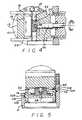
- FIG. 1is a side view of an embodiment of a medical device of the present invention
- FIG. 2is a cross-sectional view taken at line 2 — 2 of FIG. 1;
- FIG. 3is a cross-sectional view taken at line 3 — 3 of FIG. 2;
- FIG. 4is a cross-sectional view taken at line 4 — 4 of FIG. 3;
- FIG. 5is a cross-sectional view taken at line 5 — 5 of FIG. 3;
- FIG. 6is a side sectional view showing the device placed on a cornea
- FIG. 7is a side sectional view showing the device cutting the cornea.
- FIG. 8is an exploded view of an alternate embodiment of a head and a ring
- FIG. 9is a cross-sectional view of the head and ring
- FIGS. 10 a-care side views showing the head being assembled to the ring taken at line 10 — 10 of FIG. 9;
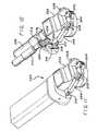
- FIG. 11is a perspective view of an alternate embodiment of the medical device.
- FIG. 12is a perspective view showing a belt and pulley mechanism of the device.
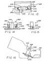
- FIG. 13is a top view of a blade holder assembly of the device
- FIG. 14is a front view of the blade holder assembly
- FIG. 15is a side view of the blade holder assembly
- FIG. 16is a side view showing the blade holder assembly within a head of the device
- FIG. 17is a top sectional view of a blade loader that can be used to insert the blade holder assembly into the head;
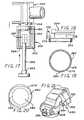
- FIG. 18is a side sectional view of a ring of the device.
- FIG. 19is a bottom view of a ring insert
- FIG. 20is a top sectional view showing an alternate embodiment of the ring
- FIG. 21is a perspective view showing a stop of the device
- FIGS. 22 a and 22 bare a schematic of a console for the device.
- FIGS. 1-5show an embodiment of a medical device 10 of the present invention.
- the device 10may include a ring 12 that is placed onto a cornea (not shown).
- the ring 12may have a port 14 which is coupled to a vacuum source (not shown).
- the vacuum sourcemay create a vacuum pressure that pulls the ring 12 onto the cornea. The vacuum pressure prevents the ring 12 from moving during a procedure.
- the device 10may have a blade 16 that is located within an opening 18 of the ring 12 .
- the blade 16can move within the opening 18 in a first direction and a second transverse direction. The simultaneous movement of the blade 16 can create a cut across the surface of the eye.
- the device 10may include a plate 19 that is mounted to the ring 12 and which flattens the cornea.
- the blade 16is attached to a blade holder 20 .
- the blade holder 20is attached to a head 22 .
- the head 22 and blade holder 20both move with the blade 16 relative to the ring 12 .
- the blade holder 20moves in the second direction while being pulled in the first direction.
- the head 22only moves in the first direction.
- the device 10includes a first drive mechanism 28 which moves the head 22 , the blade holder 20 and the blade 16 in the first direction.
- the first drive mechanism 28may include a first motor 30 that is coupled to an output shaft 32 by a gear reduction box 34 .
- the motor 30may be an electric motor.
- the motor 30may be coupled to a first gear 36 by a shaft 38 that is attached to the output shaft 32 .
- the first gear 36may be coupled to a second gear 40 that is mounted to the head 22 .
- the second gear 40may be connected to a third gear 42 by a shaft 44 .
- the third gear 42may be coupled to a gear rack 46 (see also FIG. 1 ).
- the first 36 and second 40 gearsmay be of the bevel type so that rotation of the motor output shaft 32 imparts a corresponding rotation of shaft 44 and third gear 42 . Rotation of the third gear 42 along the gear rack 46 causes the head 22 , blade holder 20 and blade 16 to move in the first direction.
- the gear rack 46may be located on a pedestal 48 that is attached to the ring 12 .
- the pedestal 48elevates the rack 46 above the cornea so that there is a low probability of an eyelash becoming stuck in the rack and pinion gear assembly.
- the device 10may also have a second drive mechanism 50 that moves the blade holder 20 and the blade 16 in the second direction.
- the second drive mechanism 50may include a second motor 52 which has an output shaft 54 .
- the motor 52may be an electric motor.
- the output shaft 54may be attached to a shaft 56 which has an eccentric cam pin 58 .
- the cam pin 58may be captured within the shaft 54 by another pin 59 .
- the eccentric cam pin 58fits within a slot 60 of the blade holder 20 .
- Rotation of the motor output shaft 54moves the pin 58 about the center axis of the shaft 56 .
- the eccentric rotation of the pin 58moves the blade holder 20 and blade 22 within a slot 62 of the head 22 in the second direction.
- the pin 58slides along the blade holder slot 60 in a vertical direction so that the blade 16 does not move into and out of the cornea.
- the output shafts 38 and 56may extend through a bulkhead 62 that is partially located within the head 22 .
- a collar 64 and clip 66attach the bulkhead 62 to the head 22 .
- the device 10may further have a lacking ring 68 for the collar 64 .
- the motors 30 and 52may be housed within a motor casing 69 .
- the first motor 30may be connected to a first input device 70 .
- the second motor 52may be connected to a second input device 72 .
- the input devices 70 and 72may be foot pedals which can be operated by a surgeon to control the actuation and speed of the motors 30 and 52 . This allows the surgeon to separately control the movement of the blade 16 in the first direction and the movement of the blade 16 in the second direction. The surgeon can thus vary the shape and size of the cut.
- the device 10may further include a controller 74 which can be programmed to control the first 28 and second 50 drive mechanisms.
- the controller 74can be used in conjunction with the input devices 70 and 72 .
- the controller 74may have programmable limit functions which limit the speed of the motors 30 and 52 .
- the ring 12is placed on a cornea 76 .
- the plate 19tends to flatten the cornea 76 adjacent to the blade 16 .
- the surgeonactuates the first 28 and second 50 drive mechanisms to move the blade 16 in the first and second directions. The movement of the blade cuts the cornea 76 .
- FIGS. 8 and 9show linear bearings of the head 22 and the ring 12 .
- the medical device 10may utilize tongue and groove bearings to couple the head 22 to the ring 12 .
- the tongue and groove linear bearingsmay be configured so that the head 22 can be inserted into the ring 12 from a vertical direction. This is to be distinguished from the dovetail arrangements used in the prior art where the head 22 must be inserted from a horizontal direction.
- the ring 12may have a first sidewall 100 and a second sidewall 102 .
- the first sidewall 100may include the gear rack 46 that is coupled to the third gear 42 shown in FIG. 1 .
- Each sidewall 100 and 102may have a generally V-shaped groove 104 and 106 , respectively.
- the grooves 104 and 106may extend along the entire length of each wall 100 and 102 .
- the head 22may have a pair of tongues 108 and 110 .
- Tongue 108can be inserted into groove 104 .
- tongue 110can be inserted into groove 106 so that the head 22 can slide across the ring 12 .
- Each tongue 108 and 110preferably has a radial outer surface. The radial surface of each tongue 108 and 110 creates contact at two points of each V-shaped groove 104 and 106 . The two point contact aligns the tongues 108 and 110 within the grooves 104 and 106 and minimizes the friction between the head 22 and the ring 12 .
- Tongue 108 and groove 104are located a distance d 1 from a base surface 112 .
- the tongue 110 and groove 106are located a distance d 2 from the base surface 112 .
- the distance d 1may be greater than the distance d 2 to provide a keying function for the assembly of the head 22 to the ring 12 .
- the unequal distancesinsure that the head 22 is assembled onto the ring 12 so that the third gear 42 is mated with the gear rack 46 .
- FIGS. 10 a-cshow a method for assembling the head 22 to the ring 12 .
- the head 22is moved toward the ring 12 in a vertical direction as indicated by the arrow.
- a portion of the first sidewall 100may have a chamfered surface 114 that tapers inwardly from the gear rack 46 to the groove 104 as shown in FIG. 8 .
- a portion of the second sidewall 102may have a chamfered surface 116 that tapers outwardly from a top surface 118 to the groove 106 .
- the inward taper of the chamfered surface 114leaves sufficient area on the top surface of the first sidewall 100 for the gear rack 46 .
- a surgeoncan push down on the head 22 so that the tongues 108 and 110 slide down the chamfered surfaces 114 and 118 .
- the head 22may be slightly tilted so that the tongue 108 clears the gear rack 46 .
- the head 22can be pushed until the tongues 108 and 110 snap into the grooves 104 and 106 to complete the assembly.
- the linear bearings of the present inventiondo not require an alignment of the tongues with the grooves and thus reduce the complexity of assembling the device.
- the tongue and groove arrangement shown in FIGS. 8 and 9may be implemented into a surgical device which has a single motor and a transmission that couples the gears to the single motor.
- the motor and transmissionmay be the same or similar to the device shown and described in U.S. Pat. No. Re. 35,421 issued to Ruiz et al., which is hereby incorporated by reference.
- FIG. 11shows an alternate embodiment of a medical device 200 .
- the devicemay include a head 202 that can move relative to a vacuum ring 204 .
- the vacuum ring 204may have a first sidewall 206 and a second sidewall 208 .
- Each sidewall 206 and 208may have a groove (not shown) that guides a corresponding linear bearing 209 of the head 202 in a manner that is the same, or similar, to the embodiment shown in FIGS. 10 a-c.
- the device 200may include a lead screw 210 that engages an inner thread (not shown) of the first sidewall 206 . Rotation of the lead screw 210 will cause the head 202 to move across the ring 204 .
- the lead screw 210may be coupled to the output shaft 212 of a motor 214 by a belt 216 and a pair of pulleys 218 and 220 .
- the device 200may also have a pair of idler wheels 222 and 224 that create tension in the belt 216 . It is desirable to provide a motor 214 that extends at an oblique angle relative to the ring 204 . The oblique angle optimizes the ergonomics for a surgeon holding the device 200 . The location of the idler wheels 222 and 224 compensates for the oblique angle between the motor 214 and the ring 204 .
- Rotation of the motor output shaft 212will turn the pulley 220 and move the belt 216 . Movement of the belt 216 will turn the pulley 218 and rotate the lead screw 210 . Rotation of the lead screw 210 will move the head 202 across the ring 204 .
- Using a belt 216 and lead screw 210 drive mechanismhas a number of advantages over the spur gear, rack and pinion arrangements used in the prior art and shown in FIGS. 6 and 7.
- the belt 216 and lead screw 210reduce wear and crowning. Additionally, the vibration energy may be transferred into the blade by the spur gears. The vibrating blade may create an undesirable cut of the cornea.
- the belt 216may provide a damping element that can absorb vibration and prevent the transfer of energy into the blade.
- the device 200may include a motor 226 that can move a blade through an eccentric cam similar to the drive mechanism shown in FIGS. 4 and 5.
- FIGS. 13, 14 , 15 and 16show a blade holder assembly 228 that is located within the head 202 .
- the assembly 228may include a blade 230 that is captured by a blade holder 232 .
- the blade holder 232may have a groove 234 that cooperates with a rotating eccentric cam (not shown) to impart a translational movement of the blade 230 .
- the assembly 228may include an insert 236 located within an opening 238 of the blade 230 .
- the insert 236may be constructed from a plastic material that deforms when the blade 230 is pushed onto the holder 232 .
- the deformed insert 236may function as a retention spring that exerts spring forces 239 .
- the spring forcesprevent the blade 230 from moving relative to the blade holder 230 during operation of the device 200 .
- the insert 236may have a pair of retractable clips 240 that can retain the blade 230 in the z-axis. The clips 240 deflect inward when the blade 230 is pushed onto the blade holder 232 and deflect back out when the blade 230 is seated in the holder 232 as shown in FIGS. 14 and 15.
- the insert 236may also have a pair of spring levers 240 .
- Each lever 241may have a protrusion 242 that can function as a bias spring to exert a spring force on a wall 244 of the head 202 when the assembly 228 is placed within the head cavity 246 .
- the spring force created by the protrusions 242will push the assembly 228 into a wall 248 of the head 202 .
- the wall 248may be a datum zero reference surface. Pressing the assembly 228 against a datum zero wall reduces the tolerance build-up of the assembly.
- FIG. 17discloses a blade loader 250 that can be used to load the assembly 228 into the head cavity.
- the loader 250may include a body 252 with an inner cavity 254 that receives the assembly 228 .
- the body 252may also have one or more openings 256 that are adapted to receive alignment pins 258 of the head 202 .
- the pins 258 and openings 256align the inner cavity 254 of the loader 250 with the head 202 so that the assembly 228 is accurately loaded into the head cavity.
- the assembly 228can be pushed into the head cavity 246 with a plunger 260 .
- the plunger 260can be manually actuated. Alternatively, the plunger 260 may be automatically actuated by a solenoid or other means.
- the plunger 260may have a stop 262 that can engage a surface 264 of the body 252 to limit the movement of the assembly 228 into the head cavity 246 .
- the stop 262can assist in centering the assembly 228 so that the eccentric cam can be inserted into the corresponding groove of the blade holder.
- FIGS. 18 and 19show an embodiment of the ring 202 .
- the ring 202may have a tube port 270 that can receive a vacuum tube 272 .
- the vacuum tube 272can be coupled to a source of vacuum (not shown).
- the device 200may include a ring insert 274 that is pressed into the ring 202 .
- the ring insert 274may be constructed from a plastic material that deforms when inserted into the ring 202 .
- the ring insert 274may have a recessed outer rim 276 that cooperates with the ring 202 to form an annular ring channel 278 .
- the channel 278is in fluid communication with the vacuum tube 272 and a plurality of vacuum ring openings 280 , wherein air flows through the openings 280 and into the tube 272 .
- the openings 280are placed adjacent to the cornea. The air flow through the openings 280 creates a vacuum pressure that secures the ring 202 to the cornea.
- Each opening 280preferably has a length that is greater than a width. This configuration provides an opening area sufficiently large enough to minimize pressure drops, while creating an aspect ratio that inhibits tissue occlusions within the openings 280 .
- the slit configuration of the openings 280 shown in FIG. 19is less likely to occlude than a circular opening found in rings of the prior art.
- FIG. 20shows an alternate embodiment of a ring insert 274 ′.
- the ring 274 ′may have an oblong shaped inner opening 282 .
- the oblong shapecreates additional space to compensate for the hinge 284 of the corneal flap 286 . This allows the flap 286 to be longer and provides additional corneal area that can be ablated in a LASIK procedure.
- FIG. 21shows a stop mechanism 290 of the device 200 .
- the stop mechanism 290may include a stop pin 292 that extends from the head 202 .
- the stop pin 292may engage a stop surface 294 of the second sidewall 208 .
- the stop mechanism 290limits the length of the flap created in the cornea. The distance that the stop pin 292 extends from the head 202 can be adjusted to vary the length of the flap.
- the stop surface 294is located above the top surface 296 of the ring 202 . Elevating the stop surface 294 reduces the likelihood that an eye lash or other object may extend up into the stop mechanism 290 to impede the stop pin 292 and prematurely stop the movement of the blade.
- FIGS. 22 a and 22 bshow a console 300 that can operate a medical device.
- the console 300can operate either device 10 or device 200 .
- the console 300may be coupled to a vacuum system 302 .
- the vacuum system 302may include the vacuum tube 272 that is coupled to the vacuum ring (not shown).
- the system 302may include a vacuum pump 304 that creates a vacuum pressure in the tube 272 and an accumulator 306 that provides a relatively constant vacuum pressure within the system.
- the vacuum system 302may include a solenoid actuated pressure relief valve 308 that can be switched between an open position and a closed position. In the open position the valve 308 couples the tube 272 to atmosphere to release the vacuum pressure in the system 302 .
- the vacuum system 302may also have a solenoid actuated on-off valve 310 that can be switched between an open position and a closed position. In the open position the valve 310 allows air to flow through the tube 272 . In the closed position the valve 310 prevents air from flowing through the tube 272 .
- the vacuum system 302may have a first pressure sensor 312 that is in fluid communication with the tube 272 .
- the first sensor 312provides analog output signals on lines 314 and 316 that correspond to the vacuum pressure within the tube 272 .
- the system 302may also have a second pressure sensor 318 that can sense the vacuum pressure upstream from the on-off switch 310 .
- the second sensor 318provides an analog output signal on line 320 .
- the console 300may include a micro-controller 322 that can process data and instructions in accordance with a firmware and/or hardware routine(s).
- the controller 322may have an on-board analog to digital (A/D) converter 324 that is connected to the pressure sensor lines 314 , 316 and 320 .
- the A/D converter 324converts the analog output signals from the sensors 312 and 318 to digital bit strings that can be processed by the controller 322 .
- the controller 322can provide output signals on lines 326 and 328 to switch the valves 308 and 310 , respectively.
- the console 300may include a power supply switch 330 that provides power to the valves 308 and 310 through line 332 .
- the controller 322may switch the power switch 330 with an output signal on line 334 .
- the switch 330may receive power from a power supply 336 through power bus 338 .
- the power supply 336may also provide different power levels on output busses 340 and 342 .
- power bus 338may have a voltage potential of 24 volts
- power bus 340may have a voltage of 12 volts
- bus 342may be at 5 volts.
- the power supply 336may also provide sensing output signals on lines 344 and 346 .
- the controller 322may be connected to display drivers 348 by line(s) 350 .
- the drivers 348can be connected to a 7-segment light emitting diode (LED) display 352 and/or a screen 354 by lines 356 and 358 , respectively.
- the LED 352 and/or screen 354can display various alphanumeric characters such as the vacuum pressure within the tube 272 .
- the drivers 348may also be connected to a first indicator light 360 and a second indicator light 362 .
- the first indicator light 360may be illuminated when there has been a reduction of vacuum that exceeds a predetermined value.
- the second indicator light 362may be illuminated when vacuum is provided to the device 200 .
- the indicator light 362may be illuminated when the controller 322 enables the pump 304 through line 364 and switches the valve 310 to the open position through line 328 .
- the controller 322can operate the system in accordance with a pressure sensing routing. In this routine the controller 322 reads the output signals of the pressure transducers 314 and 318 and may provide a numeric indicator of the pressure on the LED 352 and/or screen 354 . The controller 322 can also compare the pressure values with threshold value(s). If the vacuum pressure within the tube 272 exceeds a threshold value then the controller 322 may provide a message to this effect on the screen 354 . The console 300 may also emit an audio signal to alert the surgeon.
- the controller 322can also provide a diagnostic routine to determine the cause of the vacuum loss.
- the controller 322can switch the on-off valve 310 to the off position and then read the pressure from sensors 312 and 318 . If the pressure from sensor 318 is lower than sensor 312 this may provide an indication that there is a fluid leak at the ring.
- the screen 354may display a message such as RING LEAK.
- the controller 322may also compute a time rate of change of pressure from sensor 318 .
- the pressure reading from sensor 312may provide an indication that the pump 304 is malfunctioning.
- the sensor 312may also provide an indication that the vacuum pump is not properly functioning even though the tube appears to have an adequate vacuum pressure because of an occlusion in the ring opening(s). It is imperative that the vacuum system always have a vacuum pressure sufficient to maintain the position of the ring during the cutting procedure.
- the controller 322may provide output signals on lines 366 and 368 to control device motors 30 , 214 and 52 , 226 .
- the signalsmay be provided to a 3-phase brushless DC motor driver 370 that can control the speed of the motors 30 , 214 and 52 , 226 .
- the voltage levels of the motorscan be fed back to the controller 322 on lines 374 and 376 .
- the driver 370can determine the actual motor speed by sensing the back emf of the motor or other means.
- the speed of each motor 30 , 214 and 52 , 226can be provided on lines 378 and 380 , respectively.
- the controller 322may utilize the actual speed of each motor to provide a closed feedback control of the motors.
- the speed signalsmay be provided to the controller 322 through a safety “watchdog” circuit 382 .
- the circuit 382may relay the signals to the controller 322 on line 384 .
- the safety circuit 382may receive input signals from the controller 322 on lines 386 , 388 and 390 .
- the circuit 382may also generate a watchdog signal on line 392 .
- the watchdog signal 392may be provided to the driver 370 to turn off the motors and the power switch 330 to release the vacuum in the tube 272 .
- the relief valve 308may be normally open so that the termination of power will open the valve 308 .
- the on-off valve 310may be normally closed so that a termination of power closes the valve 310 .
- the console 300may also have a brushed DC motor driver 394 that is connected to a single motor 396 that moves the blade in both directions.
- the driver 394may receive input signals from the controller 322 on lines 398 , 400 and 402 .
- the speed of the motor 396can be provided on line 404 .
- the inclusion of the driver 394makes the console compatible with different types of devices including devices with either a single motor or two motors.
- Control lines 344 , 346 , 374 , 376 , 404 , 406 and 408can be coupled to the A/D converter 324 through an analog multiplexor 410 .
- Control line 406can provide a feedback signal from the power switch 330 .
- the output of the multiplexor 410can be provided to the A/D converter 324 on line 412 .
- the multiplexorcan be selected through line(s) 414 .
- the multiplexorallows additional inputs to be provided to a conventional 8 pin A/D converter 324 .
- the A/D converter 324may receive a reference voltage on line 416 . The reference voltages can be compared to determine safety characteristics of the console.
- Control line 417is connected to a knob that can be rotated by a user. Rotation of the knob varies the voltage to the controller 322 .
- the voltagecan be associated with a variable parameter depending upon the state of switches 418 , 420 , 422 and 424 . If none of the switches 418 , 420 , 422 or 424 are closed then the voltage of line 417 is associated with a maximum pre-set vacuum pressure.
- the controller 322will control the vacuum system 302 so that the vacuum pressure does not exceed the maximum pre-set value. The maximum vacuum pressure can be adjusted by rotating the knob.
- closing switch 418the user can adjust the volume of an audible tone created to warn the surgeon of an inadequate vacuum pressure.
- the usercan adjust the speed of motor 30 , 214 and thus the tracking speed of the blade.
- Closing switch 422allows the user to adjust the speed of motor 52 , 226 and the cutting speed of the blade.
- the usercan adjust the amount of vacuum loss that is acceptable before the indicator is activated by closing switch 424 .
- This parametermay be used to set the threshold value for the indicator 360 .
- the values associated with motor speed, etc.may be stored in a non-volatile memory device such as an EEPROM 428 .
- the switchesmay be located at the rear panel of the console so that someone does not inadvertently change the settings.
- the console 300may have another switch 426 that can be closed to initiate the vacuum system.
- this switch 426is closed, the pump 304 is enabled, the relief valve 308 is closed and the on-off valve 310 is opened.
- the vacuum system 302may also be activated by depressing a button of a foot pedal 430 that is connected to console by line 432 .
- the controller 322may also be connected to a second foot pedal 434 by lines 436 and 438 .
- the foot pedal 434may have a pair of buttons. One button can be depressed to activate the motors and cause the head to move in a “forward” direction. The other button can be depressed to move the head in a “backward” direction.
- the surgeoncan place the ring on the cornea and then initiate the vacuum system 302 by closing switch 426 or actuating the foot pedal 430 .
- the surgeoncan then activate the motors 30 , 214 and 52 , 226 by actuating the foot pedal 434 .
- the controller 322can control the motor speed through the closed feedback loop.
- the controller 322can also monitor the pressure of the vacuum system 302 and provide an indication of both the vacuum pressure and when the pressure exceeds a threshold value.
- the console of the present inventionthus provides information to the surgeon regarding the pressure of the vacuum system.
Landscapes
- Health & Medical Sciences (AREA)
- Ophthalmology & Optometry (AREA)
- Heart & Thoracic Surgery (AREA)
- Surgery (AREA)
- Engineering & Computer Science (AREA)
- Biomedical Technology (AREA)
- Nuclear Medicine, Radiotherapy & Molecular Imaging (AREA)
- Vascular Medicine (AREA)
- Life Sciences & Earth Sciences (AREA)
- Animal Behavior & Ethology (AREA)
- General Health & Medical Sciences (AREA)
- Public Health (AREA)
- Veterinary Medicine (AREA)
- Surgical Instruments (AREA)
Abstract
Description
Claims (8)
Priority Applications (2)
| Application Number | Priority Date | Filing Date | Title |
|---|---|---|---|
| US10/272,567US6702832B2 (en) | 1999-07-08 | 2002-10-15 | Medical device for cutting a cornea that has a vacuum ring with a slitted vacuum opening |
| US10/769,412US7658746B2 (en) | 1999-07-08 | 2004-01-30 | Vacuum ring with linear bearings for an automated corneal shaper |
Applications Claiming Priority (2)
| Application Number | Priority Date | Filing Date | Title |
|---|---|---|---|
| US34983599A | 1999-07-08 | 1999-07-08 | |
| US10/272,567US6702832B2 (en) | 1999-07-08 | 2002-10-15 | Medical device for cutting a cornea that has a vacuum ring with a slitted vacuum opening |
Related Parent Applications (1)
| Application Number | Title | Priority Date | Filing Date |
|---|---|---|---|
| US34983599ADivision | 1999-07-08 | 1999-07-08 |
Related Child Applications (1)
| Application Number | Title | Priority Date | Filing Date |
|---|---|---|---|
| US10/769,412ContinuationUS7658746B2 (en) | 1999-07-08 | 2004-01-30 | Vacuum ring with linear bearings for an automated corneal shaper |
Publications (2)
| Publication Number | Publication Date |
|---|---|
| US20030045895A1 US20030045895A1 (en) | 2003-03-06 |
| US6702832B2true US6702832B2 (en) | 2004-03-09 |
Family
ID=23374155
Family Applications (3)
| Application Number | Title | Priority Date | Filing Date |
|---|---|---|---|
| US10/272,567Expired - LifetimeUS6702832B2 (en) | 1999-07-08 | 2002-10-15 | Medical device for cutting a cornea that has a vacuum ring with a slitted vacuum opening |
| US10/366,986AbandonedUS20030220662A1 (en) | 1999-07-08 | 2003-05-23 | Vacuum ring with linear bearings for an automated corneal shaper |
| US10/769,412Expired - LifetimeUS7658746B2 (en) | 1999-07-08 | 2004-01-30 | Vacuum ring with linear bearings for an automated corneal shaper |
Family Applications After (2)
| Application Number | Title | Priority Date | Filing Date |
|---|---|---|---|
| US10/366,986AbandonedUS20030220662A1 (en) | 1999-07-08 | 2003-05-23 | Vacuum ring with linear bearings for an automated corneal shaper |
| US10/769,412Expired - LifetimeUS7658746B2 (en) | 1999-07-08 | 2004-01-30 | Vacuum ring with linear bearings for an automated corneal shaper |
Country Status (1)
| Country | Link |
|---|---|
| US (3) | US6702832B2 (en) |
Cited By (33)
| Publication number | Priority date | Publication date | Assignee | Title |
|---|---|---|---|---|
| US20030018347A1 (en)* | 2001-07-23 | 2003-01-23 | Ioannis Pallikaris | Device for separating the epithelium layer from the surface of the cornea of an eye |
| US20040220599A1 (en)* | 2001-07-23 | 2004-11-04 | Fos Holding S.A. | Device for separating the epithelium layer from the surface of the cornea of an eye |
| US20040260320A1 (en)* | 2002-12-10 | 2004-12-23 | Lisk James R. | Disposable separator for separating the epithelium layer from the cornea of an eye |
| US20040260321A1 (en)* | 2002-12-19 | 2004-12-23 | Ming-Kok Tai | Apparatus and method for separating the epithelium layer from the cornea of an eye without corneal pre-applanation |
| US20070016160A1 (en)* | 2005-07-07 | 2007-01-18 | Eisai Co., Ltd. | Recovery system |
| US20070203479A1 (en)* | 2003-02-13 | 2007-08-30 | Coaptus Medical Corporation | Transseptal closure of a patent foramen ovale and other cardiac defects |
| US20070208362A1 (en)* | 2006-03-01 | 2007-09-06 | Rod Ross | Microkeratome with a detachable head |
| US20070265650A1 (en)* | 2001-07-23 | 2007-11-15 | Ioannis Pallikaris | Device for separating the epithelial layer from the surface of the cornea of an eye |
| US20080156377A1 (en)* | 2006-12-29 | 2008-07-03 | Brad Mann | Recovery system |
| US20090157096A1 (en)* | 2007-12-13 | 2009-06-18 | Zimmer Orthopaedic Surgical Products, Inc. | Dermatome With Orientation Guides |
| US20090157095A1 (en)* | 2007-12-13 | 2009-06-18 | Zimmer Orthopaedic Surgical Products, Inc. | Dermatome Blade Assembly |
| US20130197391A1 (en)* | 2009-04-15 | 2013-08-01 | Bard Peripheral Vascular, Inc. | Biopsy apparatus having integrated fluid management |
| US8690793B2 (en) | 2009-03-16 | 2014-04-08 | C. R. Bard, Inc. | Biopsy device having rotational cutting |
| US8702622B2 (en) | 2005-01-31 | 2014-04-22 | C.R. Bard, Inc. | Quick cycle biopsy system |
| US8721563B2 (en) | 2005-08-10 | 2014-05-13 | C. R. Bard, Inc. | Single-insertion, multiple sample biopsy device with integrated markers |
| US8728004B2 (en) | 2003-03-29 | 2014-05-20 | C.R. Bard, Inc. | Biopsy needle system having a pressure generating unit |
| US8771200B2 (en) | 2005-08-10 | 2014-07-08 | C.R. Bard, Inc. | Single insertion, multiple sampling biopsy device with linear drive |
| US8808197B2 (en) | 2009-10-29 | 2014-08-19 | Bard Peripheral Vascular, Inc. | Biopsy driver assembly having a control circuit for conserving battery power |
| US8858463B2 (en) | 2007-12-20 | 2014-10-14 | C. R. Bard, Inc. | Biopsy device |
| US8864680B2 (en) | 2004-07-09 | 2014-10-21 | Bard Peripheral Vascular, Inc. | Transport system for biopsy device |
| US8951209B2 (en) | 2002-03-19 | 2015-02-10 | C. R. Bard, Inc. | Biopsy device and insertable biopsy needle module |
| US8951208B2 (en) | 2006-08-21 | 2015-02-10 | C. R. Bard, Inc. | Self-contained handheld biopsy needle |
| US8961430B2 (en) | 2005-08-10 | 2015-02-24 | C.R. Bard, Inc. | Single-insertion, multiple sampling biopsy device usable with various transport systems and integrated markers |
| US9072502B2 (en) | 2002-03-19 | 2015-07-07 | C. R. Bard, Inc. | Disposable biopsy unit |
| US9173641B2 (en) | 2009-08-12 | 2015-11-03 | C. R. Bard, Inc. | Biopsy apparatus having integrated thumbwheel mechanism for manual rotation of biopsy cannula |
| US9282949B2 (en) | 2009-09-01 | 2016-03-15 | Bard Peripheral Vascular, Inc. | Charging station for battery powered biopsy apparatus |
| US9566045B2 (en) | 2006-10-06 | 2017-02-14 | Bard Peripheral Vascular, Inc. | Tissue handling system with reduced operator exposure |
| US10123819B2 (en) | 2015-04-14 | 2018-11-13 | Zimmer Surgical, Inc. | Multi-piece dermatome body |
| US10149664B2 (en) | 2006-10-24 | 2018-12-11 | C. R. Bard, Inc. | Large sample low aspect ratio biopsy needle |
| US10285673B2 (en) | 2013-03-20 | 2019-05-14 | Bard Peripheral Vascular, Inc. | Biopsy device |
| US10456120B2 (en) | 2013-11-05 | 2019-10-29 | C. R. Bard, Inc. | Biopsy device having integrated vacuum |
| US10463350B2 (en) | 2015-05-01 | 2019-11-05 | C. R. Bard, Inc. | Biopsy device |
| US20230181276A1 (en)* | 2021-12-13 | 2023-06-15 | Covidien Lp | Foot pedal two stage button and rearrange for a surgical robotic system |
Families Citing this family (15)
| Publication number | Priority date | Publication date | Assignee | Title |
|---|---|---|---|---|
| US6818004B2 (en)* | 2001-10-24 | 2004-11-16 | Cesar C. Carriazo | Aspherical positioning ring |
| DE602004026592D1 (en)* | 2003-07-29 | 2010-05-27 | Koninkl Philips Electronics Nv | ELECTROMAGNETIC RADIATION DISCHARGE DEVICE |
| EP1743609A1 (en)* | 2005-07-12 | 2007-01-17 | Wavelight Laser Technologie AG | Ophthalmic surgery apparatus |
| EP1752120B1 (en)* | 2005-08-12 | 2008-12-10 | Wavelight Laser Technologie AG | Device for inserting a blade holder into a microsurgical cutting instrument, with a blade unit |
| US7875045B2 (en)* | 2006-02-02 | 2011-01-25 | Nidek Co., Ltd. | Corneal incision apparatus and blade case for storing blade unit to be mounted in the corneal incision apparatus |
| US20090234333A1 (en)* | 2006-03-01 | 2009-09-17 | Ross Rodney L | Microkeratome and cutting head with non-coplanar applanation plate and stromal plate |
| US8382781B2 (en)* | 2010-09-30 | 2013-02-26 | Wavelight Gmbh | Device for ophthalmic surgery |
| KR101496223B1 (en)* | 2010-09-30 | 2015-02-26 | 웨이브라이트 게엠베하 | Device for eye surgery |
| CN105228688B (en) | 2013-03-15 | 2019-02-19 | 伊瑟拉医疗公司 | Vascular treatment devices and methods |
| JP6526374B2 (en)* | 2013-04-25 | 2019-06-05 | 株式会社堀場エステック | Fluid control device |
| CN104605975B (en)* | 2015-02-06 | 2016-08-24 | 邓欣然 | A kind of discission needle |
| CN108697423A (en) | 2016-02-16 | 2018-10-23 | 伊瑟拉医疗公司 | The part flow arrangement of suction unit and anchoring |
| CA3076901A1 (en) | 2017-09-26 | 2019-04-04 | William F. Wiley | Self-contained ocular surgery instrument |
| USD847864S1 (en) | 2018-01-22 | 2019-05-07 | Insera Therapeutics, Inc. | Pump |
| US20240252356A1 (en)* | 2023-01-28 | 2024-08-01 | Med-Logics, Inc. | Microkeratome blade assemblies having channels for stabilizing movement |
Citations (224)
| Publication number | Priority date | Publication date | Assignee | Title |
|---|---|---|---|---|
| US1841968A (en) | 1924-08-16 | 1932-01-19 | William J Cameron | Radio-surgical apparatus |
| US1847658A (en) | 1925-01-26 | 1932-03-01 | Lasker Edward | Breast pump |
| US2070281A (en) | 1935-07-12 | 1937-02-09 | Leggiadro Vincent | Surgical knife |
| US2480737A (en) | 1948-03-08 | 1949-08-30 | Jayle Gaetan Jean-Edward | Cutting instrument particularly useful in connection with corneal grafting |
| USRE23496E (en) | 1952-05-20 | Seeler | ||
| US2708437A (en) | 1952-03-31 | 1955-05-17 | Elizabeth Painter Hutchins | Surgical instrument |
| US2824455A (en) | 1952-06-27 | 1958-02-25 | Milwaukee Electric Tool Corp | Portable reciprocating saw |
| US3033196A (en) | 1957-09-16 | 1962-05-08 | Air Reduction | Artificial respiration apparatus |
| US3252623A (en) | 1965-07-22 | 1966-05-24 | C F Liquidation Corp | Apparatus for monitoring dispensing of liquid |
| US3266494A (en) | 1963-08-26 | 1966-08-16 | Possis Machine Corp | Powered forceps |
| US3308828A (en) | 1963-08-08 | 1967-03-14 | Eugene E Bernard | Craniotomy instrument |
| US3399677A (en) | 1966-07-01 | 1968-09-03 | Goodrich Co B F | Catheter and valve therefor |
| US3511162A (en) | 1969-02-20 | 1970-05-12 | Johnson & Johnson | Apparatus and method for isolating a patient zone |
| US3561429A (en) | 1968-05-23 | 1971-02-09 | Eversharp Inc | Instrument for obtaining a biopsy specimen |
| US3583403A (en) | 1967-06-27 | 1971-06-08 | Austenal Europa Inc | Dermatome |
| US3589363A (en) | 1967-07-25 | 1971-06-29 | Cavitron Corp | Material removal apparatus and method employing high frequency vibrations |
| US3624821A (en) | 1969-09-17 | 1971-11-30 | Stanford A Henderson | Suction pump |
| US3693613A (en) | 1970-12-09 | 1972-09-26 | Cavitron Corp | Surgical handpiece and flow control system for use therewith |
| US3723030A (en) | 1971-03-03 | 1973-03-27 | Buchler Instr Division | Peristaltic pump with stacked components |
| US3752161A (en) | 1971-08-02 | 1973-08-14 | Minnesota Mining & Mfg | Fluid operated surgical tool |
| US3763862A (en) | 1970-02-06 | 1973-10-09 | Duerr Dental Kg | Arrangement at a suction installation for medicinal hygienic and cosmetic purposes |
| US3812855A (en) | 1971-12-15 | 1974-05-28 | Surgical Design Corp | System for controlling fluid and suction pressure |
| US3815604A (en) | 1972-06-19 | 1974-06-11 | Malley C O | Apparatus for intraocular surgery |
| US3841799A (en) | 1971-08-23 | 1974-10-15 | East West Med Prod | Medical cassette pump |
| US3842839A (en) | 1973-04-05 | 1974-10-22 | L Malis | Rongeur |
| US3882872A (en) | 1970-01-05 | 1975-05-13 | Nicholas G Douvas | Method and apparatus for cataract surgery |
| US3884238A (en) | 1972-06-19 | 1975-05-20 | Malley Conor C O | Apparatus for intraocular surgery |
| US3899829A (en) | 1974-02-07 | 1975-08-19 | Fred Storm Ind Designs Inc | Holder and actuator means for surgical instruments |
| US3903881A (en) | 1974-04-12 | 1975-09-09 | Bourns Inc | Respirator system and method |
| US3913584A (en) | 1974-06-28 | 1975-10-21 | Xomox Corp | Combination myringotomy scalpel, aspirator and otological vent tube inserter |
| US3920014A (en) | 1971-12-15 | 1975-11-18 | Anton Banko | Surgical system for controlling the infusion of fluid to and the evacuation of fluid and material from an operating field |
| US3930505A (en) | 1974-06-24 | 1976-01-06 | Hydro Pulse Corporation | Surgical apparatus for removal of tissue |
| US3945117A (en) | 1973-02-15 | 1976-03-23 | Rudolph Beaver, Inc. | Surgical blade with adjustable blade guard |
| US3977425A (en) | 1972-12-04 | 1976-08-31 | Tokico Ltd. | Hydraulic pressure control valve |
| US3983474A (en) | 1975-02-21 | 1976-09-28 | Polhemus Navigation Sciences, Inc. | Tracking and determining orientation of object using coordinate transformation means, system and process |
| US3982539A (en) | 1974-08-16 | 1976-09-28 | Health Technology Labs, Inc. | Medical/surgical suction equipment |
| US3986512A (en) | 1973-12-21 | 1976-10-19 | M. Schaerer A.G. | Osteotome |
| US4004590A (en) | 1974-11-15 | 1977-01-25 | Health Technology Laboratories, Inc. | Medical/surgical suction equipment |
| US4011869A (en) | 1975-08-01 | 1977-03-15 | David Kopf Instruments | Tubular cutting instrument |
| DE2547185A1 (en) | 1975-10-22 | 1977-04-28 | Hennig Juergen | Hand operated surgical instrument with hinged arms - has pneumatic or hydraulic power system to provide motion energy for the hinged arms |
| US4034712A (en) | 1975-11-24 | 1977-07-12 | Duncan Lloyd P | Pulsation system |
| US4043342A (en) | 1974-08-28 | 1977-08-23 | Valleylab, Inc. | Electrosurgical devices having sesquipolar electrode structures incorporated therein |
| US4108182A (en) | 1977-02-16 | 1978-08-22 | Concept Inc. | Reciprocation vitreous suction cutter head |
| US4135515A (en) | 1975-12-03 | 1979-01-23 | Health Technology Laboratories, Inc. | Medical/surgical suction equipment |
| US4137920A (en) | 1976-01-20 | 1979-02-06 | Richarg Wolf Gmbh | Endoscopes |
| US4168707A (en) | 1977-06-13 | 1979-09-25 | Douvas Nicholas G | Control apparatus for microsurgical instruments |
| US4173980A (en) | 1977-02-25 | 1979-11-13 | Curtin Brian J | Corneal resurfacing apparatus and method |
| US4178707A (en) | 1977-07-18 | 1979-12-18 | Littlefield John V | Display apparatus utilizing magnetic materials |
| US4204328A (en) | 1977-11-14 | 1980-05-27 | Kutner Barry S | Variable diameter aspirating tip |
| US4205682A (en) | 1976-09-17 | 1980-06-03 | The University Of Melbourne | Contact lens corneal cutter |
| US4210146A (en) | 1978-06-01 | 1980-07-01 | Anton Banko | Surgical instrument with flexible blade |
| US4217993A (en) | 1977-12-02 | 1980-08-19 | Baxter Travenol Laboratories, Inc. | Flow metering apparatus for a fluid infusion system |
| US4223676A (en) | 1977-12-19 | 1980-09-23 | Cavitron Corporation | Ultrasonic aspirator |
| US4245815A (en) | 1979-02-23 | 1981-01-20 | Linear Dynamics, Inc. | Proportional solenoid valve and connector |
| US4246902A (en) | 1978-03-10 | 1981-01-27 | Miguel Martinez | Surgical cutting instrument |
| US4274411A (en) | 1979-03-30 | 1981-06-23 | Dotson Robert S Jun | Fluid operated ophthalmic irrigation and aspiration device |
| US4301802A (en) | 1980-03-17 | 1981-11-24 | Stanley Poler | Cauterizing tool for ophthalmological surgery |
| US4304262A (en) | 1979-04-11 | 1981-12-08 | Westfalia Separator Ag | Device for controlling actuators by means of pneumatic pulses |
| US4308385A (en) | 1979-05-09 | 1981-12-29 | Stamicarbon, B. V. | Process for purifying urea-containing waste water and process for preparing melamine |
| US4308835A (en) | 1980-01-25 | 1982-01-05 | Abbey Harold | Closed-loop fluidic control system for internal combustion engines |
| US4314560A (en) | 1979-11-28 | 1982-02-09 | Helfgott Maxwell A | Powered handpiece for endophthalmic surgery |
| US4319899A (en) | 1980-04-28 | 1982-03-16 | Pure Air Corporation | Air handling system for laminar flow clean enclosure |
| US4320761A (en) | 1979-02-06 | 1982-03-23 | Haddad Heskel M | Surgical device for excision of tissue |
| US4344784A (en) | 1981-02-27 | 1982-08-17 | Dexon, Inc. | Filter assembly for clean air rooms and work stations |
| US4354838A (en) | 1980-05-06 | 1982-10-19 | Sybron Corporation | Foot controller for dental instruments or the like |
| US4395258A (en) | 1980-11-03 | 1983-07-26 | Cooper Medical Devices | Linear intra-ocular suction device |
| US4396386A (en) | 1981-05-07 | 1983-08-02 | Bioresearch Inc. | Surgical drainage apparatus with suction control and indication |
| US4427427A (en) | 1982-01-19 | 1984-01-24 | Veco S.A. | Vertical laminar flow filter module |
| US4428748A (en) | 1980-04-09 | 1984-01-31 | Peyman Gholam A | Combined ultrasonic emulsifier and mechanical cutter for surgery |
| US4429696A (en) | 1980-09-03 | 1984-02-07 | Sevifra S.A. | Surgical apparatus for precisely cutting out the cornea |
| US4445517A (en) | 1981-09-28 | 1984-05-01 | Feild James Rodney | Suction dissector |
| US4474411A (en) | 1980-11-08 | 1984-10-02 | Gewerkschaft Eisenhutte Westfalia | Guides for mineral mining machines |
| US4475904A (en) | 1982-12-29 | 1984-10-09 | Medical Instrument Dev. Labs., Inc. | Fast response vacuum aspiration collection system |
| US4476862A (en) | 1980-12-08 | 1984-10-16 | Pao David S C | Method of scleral marking |
| US4479717A (en) | 1981-06-23 | 1984-10-30 | Compagnie Industrielle Des Lasers Cilas Alcatel | Apparatus for measuring the position of an object |
| US4481948A (en) | 1980-12-29 | 1984-11-13 | Sole Gary M | Medical instrument, and methods of constructing and utilizing same |
| US4493695A (en) | 1982-06-01 | 1985-01-15 | Site Microsurgical Systems, Inc. | Opthalmic microsurgical system cassette assembly |
| US4493698A (en) | 1980-11-03 | 1985-01-15 | Cooper Medical Devices | Method of performing opthalmic surgery utilizing a linear intra-ocular suction device |
| US4522371A (en) | 1983-06-20 | 1985-06-11 | Borg-Warner Corporation | Proportional solenoid valve |
| US4523911A (en) | 1983-01-26 | 1985-06-18 | Kaltenbach & Voight Gmbh & Co. | Foot-actuated control arrangment particularly for dental arrangment |
| US4524948A (en) | 1983-09-09 | 1985-06-25 | Ranco Incorporated | Electrically controlled pressure transducer valve |
| US4530357A (en) | 1983-04-18 | 1985-07-23 | Pawloski James A | Fluid actuated orthopedic tool |
| US4531934A (en) | 1982-04-13 | 1985-07-30 | Gorkovsky Gosudarstvenny Meditsinsky Institute Imini S.M. Kirova | Apparatus for the fragmentation and aspiration of ocular tissue |
| US4540406A (en) | 1983-05-02 | 1985-09-10 | Thoratec Laboratories Corporation | Anticoagulant delivery system for use with an auto-transfusion system |
| US4555645A (en) | 1982-12-01 | 1985-11-26 | Snyder Laboratories, Inc. | Moveable coil linear motor |
| US4560395A (en) | 1984-04-17 | 1985-12-24 | Environmental Air Control, Inc. | Compact blower and filter assemblies for use in clean air environments |
| US4583539A (en)* | 1982-01-12 | 1986-04-22 | Cornell Research Foundation, Inc. | Laser surgical system |
| US4589414A (en) | 1983-04-27 | 1986-05-20 | Olympus Optical Co., Ltd. | Surgical cutting instrument |
| US4598729A (en) | 1981-06-19 | 1986-07-08 | Nippondenso Co., Ltd. | Negative pressure control valve |
| FR2549727B1 (en) | 1983-07-08 | 1986-11-28 | Andre Zoulalian | DESOBSTRUCTION APPARATUS, IN PARTICULAR DEVICE FOR SUCTION OF MUCOSITES |
| US4647209A (en) | 1984-02-13 | 1987-03-03 | Haenni & Cie Ag | Optical measuring instrument for the contactless measurement of distances |
| US4660556A (en) | 1985-02-14 | 1987-04-28 | Techno Opthalmics International, Inc. | Method and apparatus for modifying corneal buttons |
| US4660970A (en) | 1983-11-25 | 1987-04-28 | Carl-Zeiss-Stiftung | Method and apparatus for the contact-less measuring of objects |
| US4662370A (en) | 1984-09-13 | 1987-05-05 | Carl-Zeiss-Stiftung | Apparatus for performing lamellar refractive corneal surgery |
| US4665914A (en) | 1985-12-27 | 1987-05-19 | Emanuel Tanne | Automatic corneal surgery system |
| US4674499A (en) | 1980-12-08 | 1987-06-23 | Pao David S C | Coaxial bipolar probe |
| US4674503A (en) | 1981-03-05 | 1987-06-23 | Peyman Gholam A | Controlled depth penetrant apparatus and method |
| US4678459A (en) | 1984-07-23 | 1987-07-07 | E-Z-Em, Inc. | Irrigating, cutting and aspirating system for percutaneous surgery |
| US4688570A (en) | 1981-03-09 | 1987-08-25 | The Regents Of The University Of California | Ophthalmologic surgical instrument |
| US4690099A (en) | 1984-11-27 | 1987-09-01 | The National Dairy Association Of N.Z. | Pulsation arrangement |
| US4701049A (en) | 1983-06-22 | 1987-10-20 | B.V. Optische Industrie "De Oude Delft" | Measuring system employing a measuring method based on the triangulation principle for the non-contact measurement of a distance from the surface of a contoured object to a reference level. _ |
| US4705395A (en) | 1984-10-03 | 1987-11-10 | Diffracto Ltd. | Triangulation data integrity |
| US4706687A (en) | 1985-02-28 | 1987-11-17 | Alcon Instrumentation, Inc. | Linear suction control system |
| US4723545A (en) | 1986-02-03 | 1988-02-09 | Graduate Hospital Foundation Research Corporation | Power assisted arthroscopic surgical device |
| US4743770A (en) | 1986-09-22 | 1988-05-10 | Mitutoyo Mfg. Co., Ltd. | Profile-measuring light probe using a change in reflection factor in the proximity of a critical angle of light |
| US4757814A (en) | 1985-02-28 | 1988-07-19 | Alcon Laboratories, Inc. | Proportional control for pneumatic cutting device |
| US4759363A (en) | 1985-09-17 | 1988-07-26 | Jensen Ronald P | Scalpel with removable depth guard |
| US4767403A (en) | 1987-02-09 | 1988-08-30 | The Boc Group, Inc. | Positive pulse device and system |
| US4768506A (en) | 1985-09-26 | 1988-09-06 | Alcon Laboratories, Inc. | Handpiece drive apparatus for powered surgical scissors |
| US4770654A (en) | 1985-09-26 | 1988-09-13 | Alcon Laboratories Inc. | Multimedia apparatus for driving powered surgical instruments |
| US4782239A (en) | 1985-04-05 | 1988-11-01 | Nippon Kogaku K. K. | Optical position measuring apparatus |
| US4782849A (en) | 1987-02-09 | 1988-11-08 | The Boc Group, Inc. | Control unit for intermittent suction system |
| US4791934A (en) | 1986-08-07 | 1988-12-20 | Picker International, Inc. | Computer tomography assisted stereotactic surgery system and method |
| US4805615A (en) | 1985-07-02 | 1989-02-21 | Carol Mark P | Method and apparatus for performing stereotactic surgery |
| US4805616A (en) | 1980-12-08 | 1989-02-21 | Pao David S C | Bipolar probes for ophthalmic surgery and methods of performing anterior capsulotomy |
| US4807623A (en) | 1986-05-30 | 1989-02-28 | David M. Lieberman | Device for simultaneously forming two incisions along a path on an eye |
| US4819635A (en) | 1987-09-18 | 1989-04-11 | Henry Shapiro | Tubular microsurgery cutting apparatus |
| US4825091A (en) | 1987-02-05 | 1989-04-25 | Carl-Zeiss-Stiftung | Optoelectronic distance sensor with visible pilot beam |
| US4828306A (en) | 1988-03-07 | 1989-05-09 | Blatt John A | Vacuum cup control system |
| US4830047A (en) | 1987-02-09 | 1989-05-16 | The Boc Group, Inc. | Control unit for intermittent suction system |
| US4837857A (en) | 1986-11-06 | 1989-06-06 | Storz Instrument Company | Foot pedal assembly for ophthalmic surgical instrument |
| US4838281A (en) | 1985-02-28 | 1989-06-13 | Alcon Laboratories, Inc. | Linear suction control system |
| US4840175A (en) | 1986-12-24 | 1989-06-20 | Peyman Gholam A | Method for modifying corneal curvature |
| US4865033A (en) | 1986-08-08 | 1989-09-12 | Krumeich Jorg H | Device for holding a cornea taken from a donated eye |
| US4884570A (en) | 1984-03-16 | 1989-12-05 | Eyetech Ag | Device for retaining a disc obtained from a human cornea |
| US4886085A (en) | 1988-11-30 | 1989-12-12 | General Motors Corporation | Vacuum check valve and method of control |
| US4903695A (en) | 1988-11-30 | 1990-02-27 | Lri L.P. | Method and apparatus for performing a keratomileusis or the like operation |
| US4909815A (en) | 1988-10-24 | 1990-03-20 | International Air Filter, Inc. | Mobile air cleaning apparatus |
| USRE33250E (en) | 1982-06-01 | 1990-07-03 | Site Microsurgical Systems, Inc. | Microsurgical system cassette assembly |
| US4941093A (en)* | 1985-09-12 | 1990-07-10 | Summit Technology, Inc. | Surface erosion using lasers |
| US4943289A (en) | 1989-05-03 | 1990-07-24 | Cook Pacemaker Corporation | Apparatus for removing an elongated structure implanted in biological tissue |
| US4965417A (en) | 1989-03-27 | 1990-10-23 | Massie Philip E | Foot-operated control |
| US4988347A (en) | 1988-11-09 | 1991-01-29 | Cook Pacemaker Corporation | Method and apparatus for separating a coiled structure from biological tissue |
| US4997437A (en) | 1987-08-10 | 1991-03-05 | Grieshaber Hans R | Apparatus for the surgical correction of ametropia of one or both eyes of living beings |
| US5011482A (en) | 1989-01-17 | 1991-04-30 | Cook Pacemaker Corporation | Apparatus for removing an elongated structure implanted in biological tissue |
| US5013310A (en) | 1988-11-09 | 1991-05-07 | Cook Pacemaker Corporation | Method and apparatus for removing an implanted pacemaker lead |
| US5019076A (en) | 1986-09-12 | 1991-05-28 | Yamanashi William S | Radio frequency surgical tool and method |
| US5059204A (en) | 1989-10-26 | 1991-10-22 | Site Microsurgical Systems, Inc. | Ocular cutter with enhanced cutting action |
| US5083558A (en) | 1990-11-06 | 1992-01-28 | Thomas William R | Mobile surgical compartment with micro filtered laminar air flow |
| US5098443A (en) | 1989-03-23 | 1992-03-24 | University Of Miami | Method of implanting intraocular and intraorbital implantable devices for the controlled release of pharmacological agents |
| US5106364A (en) | 1989-07-07 | 1992-04-21 | Kabushiki Kaisha Topcon | Surgical cutter |
| US5133726A (en) | 1990-02-14 | 1992-07-28 | Ruiz Luis A | Automatic corneal shaper |
| US5133713A (en) | 1990-03-27 | 1992-07-28 | Huang Jong Khing | Apparatus of a spinning type of resectoscope for prostatectomy |
| US5152786A (en)* | 1989-06-23 | 1992-10-06 | Khalil Hanna | Lense for keratometry and keratotome more particularly for making an incision for receiving such a lense |
| US5176628A (en) | 1989-10-27 | 1993-01-05 | Alcon Surgical, Inc. | Vitreous cutter |
| US5201749A (en) | 1990-09-19 | 1993-04-13 | Sachse Rainer E | Circularly oscillating saw |
| US5207683A (en) | 1988-11-09 | 1993-05-04 | Cook Pacemaker Corporation | Apparatus for removing an elongated structure implanted in biological tissue |
| US5215104A (en) | 1988-08-16 | 1993-06-01 | Steinert Roger F | Method for corneal modification |
| US5217459A (en) | 1991-08-27 | 1993-06-08 | William Kamerling | Method and instrument for performing eye surgery |
| US5224950A (en) | 1991-10-02 | 1993-07-06 | Prywes Arnold S | Color calibrated multi-function scalpel blade for intraocular and other surgery and associated methods of use |
| US5226910A (en) | 1989-07-05 | 1993-07-13 | Kabushiki Kaisha Topcon | Surgical cutter |
| US5242404A (en) | 1992-02-12 | 1993-09-07 | American Cyanamid Company | Aspiration control system |
| US5271379A (en) | 1991-07-26 | 1993-12-21 | The Regents Of The University Of California | Endoscopic device actuator and method |
| US5273406A (en) | 1991-09-12 | 1993-12-28 | American Dengi Co., Inc. | Pressure actuated peristaltic pump |
| US5273524A (en) | 1991-10-09 | 1993-12-28 | Ethicon, Inc. | Electrosurgical device |
| US5285795A (en) | 1991-09-12 | 1994-02-15 | Surgical Dynamics, Inc. | Percutaneous discectomy system having a bendable discectomy probe and a steerable cannula |
| US5322505A (en) | 1990-02-07 | 1994-06-21 | Smith & Nephew Dyonics, Inc. | Surgical instrument |
| US5330470A (en) | 1991-07-04 | 1994-07-19 | Delma Elektro-Und Medizinische Apparatebau Gesellschaft Mbh | Electro-surgical treatment instrument |
| US5354268A (en) | 1992-11-04 | 1994-10-11 | Medical Instrument Development Laboratories, Inc. | Methods and apparatus for control of vacuum and pressure for surgical procedures |
| US5364395A (en) | 1993-05-14 | 1994-11-15 | West Jr Hugh S | Arthroscopic surgical instrument with cauterizing capability |
| US5374188A (en) | 1993-07-19 | 1994-12-20 | Bei Medical Systems, Inc. | Electro-surgical instrument and method for use with dental implantations |
| US5380280A (en) | 1993-11-12 | 1995-01-10 | Peterson; Erik W. | Aspiration system having pressure-controlled and flow-controlled modes |
| US5383454A (en) | 1990-10-19 | 1995-01-24 | St. Louis University | System for indicating the position of a surgical probe within a head on an image of the head |
| US5395368A (en) | 1993-05-20 | 1995-03-07 | Ellman; Alan G. | Multiple-wire electrosurgical electrodes |
| US5403311A (en) | 1993-03-29 | 1995-04-04 | Boston Scientific Corporation | Electro-coagulation and ablation and other electrotherapeutic treatments of body tissue |
| US5403276A (en) | 1993-02-16 | 1995-04-04 | Danek Medical, Inc. | Apparatus for minimally invasive tissue removal |
| US5437678A (en) | 1992-11-30 | 1995-08-01 | Neomedix Corporation | Ophthalmic lens removal method and apparatus |
| US5465633A (en) | 1994-02-07 | 1995-11-14 | Johnson Fishing, Inc. | Foot actuated trolling motor control |
| US5474532A (en) | 1994-11-22 | 1995-12-12 | Alcon Laboratories, Inc. | Cutting blade for a vitreous cutter |
| US5476448A (en) | 1994-10-19 | 1995-12-19 | Urich; Alex | Apparatus for suppressing a vacuum surge in eye surgery |
| US5476473A (en) | 1993-01-05 | 1995-12-19 | Richard Wolf Gmbh | Instrument for surgically cutting tissue |
| US5496339A (en) | 1994-05-17 | 1996-03-05 | Koepnick; Russell G. | Universal automated keratectomy apparatus and method |
| US5507751A (en) | 1988-11-09 | 1996-04-16 | Cook Pacemaker Corporation | Locally flexible dilator sheath |
| US5520684A (en) | 1993-06-10 | 1996-05-28 | Imran; Mir A. | Transurethral radio frequency apparatus for ablation of the prostate gland and method |
| US5527332A (en) | 1994-11-02 | 1996-06-18 | Mectra Labs, Inc. | Tissue cutter for surgery |
| US5527356A (en) | 1994-08-02 | 1996-06-18 | Syntec, Inc. | Retinal plug |
| US5531744A (en) | 1991-11-01 | 1996-07-02 | Medical Scientific, Inc. | Alternative current pathways for bipolar surgical cutting tool |
| US5556397A (en) | 1994-10-26 | 1996-09-17 | Laser Centers Of America | Coaxial electrosurgical instrument |
| US5566681A (en) | 1995-05-02 | 1996-10-22 | Manwaring; Kim H. | Apparatus and method for stabilizing a body part |
| USD377524S (en) | 1995-10-05 | 1997-01-21 | Megadyne Medical Products, Inc. | Insulated electrosurgical needle |
| US5611799A (en) | 1994-06-14 | 1997-03-18 | Smith; Albert C. | Ocular repair method |
| US5624394A (en) | 1994-10-28 | 1997-04-29 | Iolab Corporation | Vacuum system and a method of operating a vacuum system |
| US5643304A (en) | 1993-02-16 | 1997-07-01 | Danek Medical, Inc. | Method and apparatus for minimally invasive tissue removal |
| US5651782A (en) | 1993-03-19 | 1997-07-29 | University Of Miami | Method and apparatus for implanting an artificial meshwork in glaucoma surgery |
| US5690658A (en) | 1993-10-06 | 1997-11-25 | Mcadams; John B. | Keratorefractive system and method |
| US5693013A (en) | 1995-01-26 | 1997-12-02 | Hans Geuder Gmbh | Apparatus for aspirating lens debris during cataract operations |
| US5700240A (en) | 1994-01-28 | 1997-12-23 | Barwick, Jr.; Billie John | Phacoemulsification system having ultrasonic power controlled by aspiration vacuum sensor |
| US5704927A (en) | 1994-06-08 | 1998-01-06 | Syntec, Inc. | Controlled vacuum in ophthalmic retinal surgery |
| US5738677A (en) | 1992-04-10 | 1998-04-14 | Premier Laser Systems, Inc. | Apparatus and method for performing eye surgery |
| US5743274A (en) | 1996-03-18 | 1998-04-28 | Peyman; Gholam A. | Macular bandage for use in the treatment of subretinal neovascular members |
| US5755700A (en) | 1995-07-27 | 1998-05-26 | Michiel S. Kritzinger | Corneal irrigation cannula and method of using |
| US5779723A (en) | 1995-10-30 | 1998-07-14 | Herbert Schwind Gmbh & Co. Kg | Device for corneal surgery |
| US5782849A (en) | 1993-05-07 | 1998-07-21 | Sdgi Holdings, Inc. | Surgical cutting instrument |
| US5787760A (en) | 1993-11-24 | 1998-08-04 | Thorlakson; Richard G. | Method and foot pedal apparatus for operating a microscope |
| US5810857A (en) | 1993-08-12 | 1998-09-22 | Mackool; Richard J. | Surgical knife for controlled lengthening of an incision |
| US5814010A (en) | 1995-08-08 | 1998-09-29 | Allergan, Inc. | Safety-vac capsule polisher |
| US5817075A (en) | 1989-08-14 | 1998-10-06 | Photogenesis, Inc. | Method for preparation and transplantation of planar implants and surgical instrument therefor |
| US5819628A (en) | 1993-11-12 | 1998-10-13 | Recot, Inc. | Replaceable blade cartridge for a centrifugal type food slicer |
| US5868728A (en) | 1995-02-28 | 1999-02-09 | Photogenesis, Inc. | Medical linear actuator for surgical delivery, manipulation, and extraction |
| US5916330A (en) | 1997-01-15 | 1999-06-29 | Ford Global Technologies, Inc. | Cable operated releasable brake pedal assembly |
| US5919185A (en)* | 1997-04-25 | 1999-07-06 | Peyman; Gholam A. | Universal implant blank for modifying corneal curvature and methods of modifying corneal curvature therewith |
| US5934285A (en) | 1995-07-27 | 1999-08-10 | Michiel S. Kritzinger | Method for reducing irregular astigmatism and debris/epithelium in the interface during lamellar corneal flap/cap surgery |
| US5938676A (en) | 1993-12-08 | 1999-08-17 | Becton, Dickinson & Company | Surgical scalpel |
| US5941250A (en) | 1996-11-21 | 1999-08-24 | University Of Louisville Research Foundation Inc. | Retinal tissue implantation method |
| US5944731A (en) | 1997-08-05 | 1999-08-31 | Hanna; Khalil | Surgical appliance for slicing a sliver from the cornea |
| US5957921A (en) | 1996-11-07 | 1999-09-28 | Optex Ophthalmologics, Inc. | Devices and methods useable for forming small openings in the lens capsules of mammalian eyes |
| US5989272A (en) | 1998-10-05 | 1999-11-23 | Barron Precision Instruments L.L.C. | Keratome for performing eye surgery and method for using same |
| US6004313A (en) | 1998-06-26 | 1999-12-21 | Visx, Inc. | Patient fixation system and method for laser eye surgery |
| US6013049A (en) | 1998-10-29 | 2000-01-11 | Allergan Sales, Inc. | Controlled outflow sleeve |
| US6019754A (en) | 1998-10-29 | 2000-02-01 | Kawesch; Glenn | Method and apparatus for improving lasik flap adherence |
| US6045563A (en) | 1998-06-19 | 2000-04-04 | Moria Sa | Artificial chamber for extracting a corneal graft |
| US6051009A (en)* | 1996-02-07 | 2000-04-18 | Hellenkamp; Johann F. | Automatic surgical device for cutting a cornea and a cutting blade assembly and control assembly |
| US6059805A (en) | 1998-03-31 | 2000-05-09 | Nidek Co., Ltd. | Corneal surgical apparatus |
| US6083236A (en) | 1998-08-12 | 2000-07-04 | Feingold; Vladimir | Keratome method and apparatus |
| US6086544A (en) | 1999-03-31 | 2000-07-11 | Ethicon Endo-Surgery, Inc. | Control apparatus for an automated surgical biopsy device |
| EP1033120A2 (en) | 1999-03-03 | 2000-09-06 | Nidek Co., Ltd. | Corneal Surgical apparatus |
| US6165189A (en) | 1999-02-10 | 2000-12-26 | Sis, Ltd. | Microkeratome for performing lasik surgery |
| US6217594B1 (en) | 1999-10-21 | 2001-04-17 | Retinalabs.Com, Inc. | Apparatus, system and method for securing scleral tissue |
| US6221067B1 (en)* | 1995-10-20 | 2001-04-24 | Gholam A. Peyman | Corneal modification via implantation |
| US6251101B1 (en) | 1998-06-26 | 2001-06-26 | Visx, Incorporated | Surgical laser system microscope with separated ocular and objective lenses |
| US6258082B1 (en) | 1999-05-03 | 2001-07-10 | J. T. Lin | Refractive surgery and presbyopia correction using infrared and ultraviolet lasers |
| US6280470B1 (en)* | 1995-10-20 | 2001-08-28 | Gholam A. Peyman | Intrastromal corneal modification |
| US6312403B1 (en) | 1999-08-23 | 2001-11-06 | Luis Antonio Ruiz | Eye dryer, eye dryer system and method of using the same |
| US6406473B1 (en) | 1999-10-01 | 2002-06-18 | Visx, Incorporated | Patient fixation system and method for laser eye surgery |
Family Cites Families (8)
| Publication number | Priority date | Publication date | Assignee | Title |
|---|---|---|---|---|
| US2569080A (en)* | 1949-02-24 | 1951-09-25 | Trimble Ernest | Knife using a detachable razor blade |
| US3509626A (en)* | 1968-03-11 | 1970-05-05 | Eversharp Inc | Electromechanical razor operable at high frequencies |
| US3952732A (en)* | 1972-12-26 | 1976-04-27 | Shock John P | Ultrasonic cataract removal method and apparatus |
| US5591174A (en)* | 1994-02-02 | 1997-01-07 | Chiron Vision Corporation | Microkeratome and method and apparatus for calibrating a microkeratome |
| US5464417A (en)* | 1994-05-16 | 1995-11-07 | Eick; Daniel H. | Apparatus and method for supporting and cutting cornea tissue |
| US6007553A (en)* | 1996-02-07 | 1999-12-28 | Hellenkamp; Johann F. | Automatic surgical device control assembly for cutting a cornea |
| WO1998027901A1 (en)* | 1996-12-23 | 1998-07-02 | Instituto Barraquer De America | Microkeratome |
| US6183488B1 (en)* | 1998-11-06 | 2001-02-06 | Med-Logics, Inc. | Vacuum ring with linear bearings for an automated corneal shaper |
- 2002
- 2002-10-15USUS10/272,567patent/US6702832B2/ennot_activeExpired - Lifetime
- 2003
- 2003-05-23USUS10/366,986patent/US20030220662A1/ennot_activeAbandoned
- 2004
- 2004-01-30USUS10/769,412patent/US7658746B2/ennot_activeExpired - Lifetime
Patent Citations (229)
| Publication number | Priority date | Publication date | Assignee | Title |
|---|---|---|---|---|
| USRE23496E (en) | 1952-05-20 | Seeler | ||
| US1841968A (en) | 1924-08-16 | 1932-01-19 | William J Cameron | Radio-surgical apparatus |
| US1847658A (en) | 1925-01-26 | 1932-03-01 | Lasker Edward | Breast pump |
| US2070281A (en) | 1935-07-12 | 1937-02-09 | Leggiadro Vincent | Surgical knife |
| US2480737A (en) | 1948-03-08 | 1949-08-30 | Jayle Gaetan Jean-Edward | Cutting instrument particularly useful in connection with corneal grafting |
| US2708437A (en) | 1952-03-31 | 1955-05-17 | Elizabeth Painter Hutchins | Surgical instrument |
| US2824455A (en) | 1952-06-27 | 1958-02-25 | Milwaukee Electric Tool Corp | Portable reciprocating saw |
| US3033196A (en) | 1957-09-16 | 1962-05-08 | Air Reduction | Artificial respiration apparatus |
| US3308828A (en) | 1963-08-08 | 1967-03-14 | Eugene E Bernard | Craniotomy instrument |
| US3266494A (en) | 1963-08-26 | 1966-08-16 | Possis Machine Corp | Powered forceps |
| US3252623A (en) | 1965-07-22 | 1966-05-24 | C F Liquidation Corp | Apparatus for monitoring dispensing of liquid |
| US3399677A (en) | 1966-07-01 | 1968-09-03 | Goodrich Co B F | Catheter and valve therefor |
| US3583403A (en) | 1967-06-27 | 1971-06-08 | Austenal Europa Inc | Dermatome |
| US3589363A (en) | 1967-07-25 | 1971-06-29 | Cavitron Corp | Material removal apparatus and method employing high frequency vibrations |
| US3561429A (en) | 1968-05-23 | 1971-02-09 | Eversharp Inc | Instrument for obtaining a biopsy specimen |
| US3511162A (en) | 1969-02-20 | 1970-05-12 | Johnson & Johnson | Apparatus and method for isolating a patient zone |
| US3624821A (en) | 1969-09-17 | 1971-11-30 | Stanford A Henderson | Suction pump |
| US3882872A (en) | 1970-01-05 | 1975-05-13 | Nicholas G Douvas | Method and apparatus for cataract surgery |
| US3763862A (en) | 1970-02-06 | 1973-10-09 | Duerr Dental Kg | Arrangement at a suction installation for medicinal hygienic and cosmetic purposes |
| US3693613A (en) | 1970-12-09 | 1972-09-26 | Cavitron Corp | Surgical handpiece and flow control system for use therewith |
| US3723030A (en) | 1971-03-03 | 1973-03-27 | Buchler Instr Division | Peristaltic pump with stacked components |
| US3752161A (en) | 1971-08-02 | 1973-08-14 | Minnesota Mining & Mfg | Fluid operated surgical tool |
| US3841799A (en) | 1971-08-23 | 1974-10-15 | East West Med Prod | Medical cassette pump |
| US3812855A (en) | 1971-12-15 | 1974-05-28 | Surgical Design Corp | System for controlling fluid and suction pressure |
| US3920014A (en) | 1971-12-15 | 1975-11-18 | Anton Banko | Surgical system for controlling the infusion of fluid to and the evacuation of fluid and material from an operating field |
| US3884238A (en) | 1972-06-19 | 1975-05-20 | Malley Conor C O | Apparatus for intraocular surgery |
| US3815604A (en) | 1972-06-19 | 1974-06-11 | Malley C O | Apparatus for intraocular surgery |
| US3977425A (en) | 1972-12-04 | 1976-08-31 | Tokico Ltd. | Hydraulic pressure control valve |
| US3945117A (en) | 1973-02-15 | 1976-03-23 | Rudolph Beaver, Inc. | Surgical blade with adjustable blade guard |
| US3842839A (en) | 1973-04-05 | 1974-10-22 | L Malis | Rongeur |
| US3986512A (en) | 1973-12-21 | 1976-10-19 | M. Schaerer A.G. | Osteotome |
| US3899829A (en) | 1974-02-07 | 1975-08-19 | Fred Storm Ind Designs Inc | Holder and actuator means for surgical instruments |
| US3903881A (en) | 1974-04-12 | 1975-09-09 | Bourns Inc | Respirator system and method |
| US3930505A (en) | 1974-06-24 | 1976-01-06 | Hydro Pulse Corporation | Surgical apparatus for removal of tissue |
| US3913584A (en) | 1974-06-28 | 1975-10-21 | Xomox Corp | Combination myringotomy scalpel, aspirator and otological vent tube inserter |
| US3982539A (en) | 1974-08-16 | 1976-09-28 | Health Technology Labs, Inc. | Medical/surgical suction equipment |
| US4043342A (en) | 1974-08-28 | 1977-08-23 | Valleylab, Inc. | Electrosurgical devices having sesquipolar electrode structures incorporated therein |
| US4004590A (en) | 1974-11-15 | 1977-01-25 | Health Technology Laboratories, Inc. | Medical/surgical suction equipment |
| US3983474A (en) | 1975-02-21 | 1976-09-28 | Polhemus Navigation Sciences, Inc. | Tracking and determining orientation of object using coordinate transformation means, system and process |
| US4011869A (en) | 1975-08-01 | 1977-03-15 | David Kopf Instruments | Tubular cutting instrument |
| DE2547185A1 (en) | 1975-10-22 | 1977-04-28 | Hennig Juergen | Hand operated surgical instrument with hinged arms - has pneumatic or hydraulic power system to provide motion energy for the hinged arms |
| US4034712A (en) | 1975-11-24 | 1977-07-12 | Duncan Lloyd P | Pulsation system |
| US4135515A (en) | 1975-12-03 | 1979-01-23 | Health Technology Laboratories, Inc. | Medical/surgical suction equipment |
| US4137920A (en) | 1976-01-20 | 1979-02-06 | Richarg Wolf Gmbh | Endoscopes |
| US4205682A (en) | 1976-09-17 | 1980-06-03 | The University Of Melbourne | Contact lens corneal cutter |
| US4108182A (en) | 1977-02-16 | 1978-08-22 | Concept Inc. | Reciprocation vitreous suction cutter head |
| US4173980A (en) | 1977-02-25 | 1979-11-13 | Curtin Brian J | Corneal resurfacing apparatus and method |
| US4168707A (en) | 1977-06-13 | 1979-09-25 | Douvas Nicholas G | Control apparatus for microsurgical instruments |
| US4178707A (en) | 1977-07-18 | 1979-12-18 | Littlefield John V | Display apparatus utilizing magnetic materials |
| US4204328A (en) | 1977-11-14 | 1980-05-27 | Kutner Barry S | Variable diameter aspirating tip |
| US4217993A (en) | 1977-12-02 | 1980-08-19 | Baxter Travenol Laboratories, Inc. | Flow metering apparatus for a fluid infusion system |
| US4223676A (en) | 1977-12-19 | 1980-09-23 | Cavitron Corporation | Ultrasonic aspirator |
| US4246902A (en) | 1978-03-10 | 1981-01-27 | Miguel Martinez | Surgical cutting instrument |
| US4210146A (en) | 1978-06-01 | 1980-07-01 | Anton Banko | Surgical instrument with flexible blade |
| US4320761A (en) | 1979-02-06 | 1982-03-23 | Haddad Heskel M | Surgical device for excision of tissue |
| US4245815A (en) | 1979-02-23 | 1981-01-20 | Linear Dynamics, Inc. | Proportional solenoid valve and connector |
| US4274411A (en) | 1979-03-30 | 1981-06-23 | Dotson Robert S Jun | Fluid operated ophthalmic irrigation and aspiration device |
| US4304262A (en) | 1979-04-11 | 1981-12-08 | Westfalia Separator Ag | Device for controlling actuators by means of pneumatic pulses |
| US4308385A (en) | 1979-05-09 | 1981-12-29 | Stamicarbon, B. V. | Process for purifying urea-containing waste water and process for preparing melamine |
| US4314560A (en) | 1979-11-28 | 1982-02-09 | Helfgott Maxwell A | Powered handpiece for endophthalmic surgery |
| US4308835A (en) | 1980-01-25 | 1982-01-05 | Abbey Harold | Closed-loop fluidic control system for internal combustion engines |
| US4301802A (en) | 1980-03-17 | 1981-11-24 | Stanley Poler | Cauterizing tool for ophthalmological surgery |
| US4428748A (en) | 1980-04-09 | 1984-01-31 | Peyman Gholam A | Combined ultrasonic emulsifier and mechanical cutter for surgery |
| US4319899A (en) | 1980-04-28 | 1982-03-16 | Pure Air Corporation | Air handling system for laminar flow clean enclosure |
| US4354838A (en) | 1980-05-06 | 1982-10-19 | Sybron Corporation | Foot controller for dental instruments or the like |
| US4429696A (en) | 1980-09-03 | 1984-02-07 | Sevifra S.A. | Surgical apparatus for precisely cutting out the cornea |
| US4395258A (en) | 1980-11-03 | 1983-07-26 | Cooper Medical Devices | Linear intra-ocular suction device |
| US4493698A (en) | 1980-11-03 | 1985-01-15 | Cooper Medical Devices | Method of performing opthalmic surgery utilizing a linear intra-ocular suction device |
| US4474411A (en) | 1980-11-08 | 1984-10-02 | Gewerkschaft Eisenhutte Westfalia | Guides for mineral mining machines |
| US4805616A (en) | 1980-12-08 | 1989-02-21 | Pao David S C | Bipolar probes for ophthalmic surgery and methods of performing anterior capsulotomy |
| US4674499A (en) | 1980-12-08 | 1987-06-23 | Pao David S C | Coaxial bipolar probe |
| US4476862A (en) | 1980-12-08 | 1984-10-16 | Pao David S C | Method of scleral marking |
| US4481948A (en) | 1980-12-29 | 1984-11-13 | Sole Gary M | Medical instrument, and methods of constructing and utilizing same |
| US4344784A (en) | 1981-02-27 | 1982-08-17 | Dexon, Inc. | Filter assembly for clean air rooms and work stations |
| US4674503A (en) | 1981-03-05 | 1987-06-23 | Peyman Gholam A | Controlled depth penetrant apparatus and method |
| US4688570A (en) | 1981-03-09 | 1987-08-25 | The Regents Of The University Of California | Ophthalmologic surgical instrument |
| US4396386A (en) | 1981-05-07 | 1983-08-02 | Bioresearch Inc. | Surgical drainage apparatus with suction control and indication |
| US4598729A (en) | 1981-06-19 | 1986-07-08 | Nippondenso Co., Ltd. | Negative pressure control valve |
| US4479717A (en) | 1981-06-23 | 1984-10-30 | Compagnie Industrielle Des Lasers Cilas Alcatel | Apparatus for measuring the position of an object |
| US4445517A (en) | 1981-09-28 | 1984-05-01 | Feild James Rodney | Suction dissector |
| US4583539A (en)* | 1982-01-12 | 1986-04-22 | Cornell Research Foundation, Inc. | Laser surgical system |
| US4427427A (en) | 1982-01-19 | 1984-01-24 | Veco S.A. | Vertical laminar flow filter module |
| US4531934A (en) | 1982-04-13 | 1985-07-30 | Gorkovsky Gosudarstvenny Meditsinsky Institute Imini S.M. Kirova | Apparatus for the fragmentation and aspiration of ocular tissue |
| US4493695A (en) | 1982-06-01 | 1985-01-15 | Site Microsurgical Systems, Inc. | Opthalmic microsurgical system cassette assembly |
| USRE33250E (en) | 1982-06-01 | 1990-07-03 | Site Microsurgical Systems, Inc. | Microsurgical system cassette assembly |
| US4555645A (en) | 1982-12-01 | 1985-11-26 | Snyder Laboratories, Inc. | Moveable coil linear motor |
| US4475904A (en) | 1982-12-29 | 1984-10-09 | Medical Instrument Dev. Labs., Inc. | Fast response vacuum aspiration collection system |
| US4523911A (en) | 1983-01-26 | 1985-06-18 | Kaltenbach & Voight Gmbh & Co. | Foot-actuated control arrangment particularly for dental arrangment |
| US4530357A (en) | 1983-04-18 | 1985-07-23 | Pawloski James A | Fluid actuated orthopedic tool |
| US4589414A (en) | 1983-04-27 | 1986-05-20 | Olympus Optical Co., Ltd. | Surgical cutting instrument |
| US4540406A (en) | 1983-05-02 | 1985-09-10 | Thoratec Laboratories Corporation | Anticoagulant delivery system for use with an auto-transfusion system |
| US4522371A (en) | 1983-06-20 | 1985-06-11 | Borg-Warner Corporation | Proportional solenoid valve |
| US4701049A (en) | 1983-06-22 | 1987-10-20 | B.V. Optische Industrie "De Oude Delft" | Measuring system employing a measuring method based on the triangulation principle for the non-contact measurement of a distance from the surface of a contoured object to a reference level. _ |
| FR2549727B1 (en) | 1983-07-08 | 1986-11-28 | Andre Zoulalian | DESOBSTRUCTION APPARATUS, IN PARTICULAR DEVICE FOR SUCTION OF MUCOSITES |
| US4524948A (en) | 1983-09-09 | 1985-06-25 | Ranco Incorporated | Electrically controlled pressure transducer valve |
| US4660970A (en) | 1983-11-25 | 1987-04-28 | Carl-Zeiss-Stiftung | Method and apparatus for the contact-less measuring of objects |
| US4647209A (en) | 1984-02-13 | 1987-03-03 | Haenni & Cie Ag | Optical measuring instrument for the contactless measurement of distances |
| US4884570A (en) | 1984-03-16 | 1989-12-05 | Eyetech Ag | Device for retaining a disc obtained from a human cornea |
| US4560395A (en) | 1984-04-17 | 1985-12-24 | Environmental Air Control, Inc. | Compact blower and filter assemblies for use in clean air environments |
| US4678459A (en) | 1984-07-23 | 1987-07-07 | E-Z-Em, Inc. | Irrigating, cutting and aspirating system for percutaneous surgery |
| US4662370A (en) | 1984-09-13 | 1987-05-05 | Carl-Zeiss-Stiftung | Apparatus for performing lamellar refractive corneal surgery |
| US4705395A (en) | 1984-10-03 | 1987-11-10 | Diffracto Ltd. | Triangulation data integrity |
| US4690099A (en) | 1984-11-27 | 1987-09-01 | The National Dairy Association Of N.Z. | Pulsation arrangement |
| US4660556A (en) | 1985-02-14 | 1987-04-28 | Techno Opthalmics International, Inc. | Method and apparatus for modifying corneal buttons |
| US4706687A (en) | 1985-02-28 | 1987-11-17 | Alcon Instrumentation, Inc. | Linear suction control system |
| US4838281A (en) | 1985-02-28 | 1989-06-13 | Alcon Laboratories, Inc. | Linear suction control system |
| US4757814A (en) | 1985-02-28 | 1988-07-19 | Alcon Laboratories, Inc. | Proportional control for pneumatic cutting device |
| US4782239A (en) | 1985-04-05 | 1988-11-01 | Nippon Kogaku K. K. | Optical position measuring apparatus |
| US4805615A (en) | 1985-07-02 | 1989-02-21 | Carol Mark P | Method and apparatus for performing stereotactic surgery |
| US4941093A (en)* | 1985-09-12 | 1990-07-10 | Summit Technology, Inc. | Surface erosion using lasers |
| US4759363A (en) | 1985-09-17 | 1988-07-26 | Jensen Ronald P | Scalpel with removable depth guard |
| US4768506A (en) | 1985-09-26 | 1988-09-06 | Alcon Laboratories, Inc. | Handpiece drive apparatus for powered surgical scissors |
| US4770654A (en) | 1985-09-26 | 1988-09-13 | Alcon Laboratories Inc. | Multimedia apparatus for driving powered surgical instruments |
| US4665914A (en) | 1985-12-27 | 1987-05-19 | Emanuel Tanne | Automatic corneal surgery system |
| US4723545A (en) | 1986-02-03 | 1988-02-09 | Graduate Hospital Foundation Research Corporation | Power assisted arthroscopic surgical device |
| US4807623A (en) | 1986-05-30 | 1989-02-28 | David M. Lieberman | Device for simultaneously forming two incisions along a path on an eye |
| US4791934A (en) | 1986-08-07 | 1988-12-20 | Picker International, Inc. | Computer tomography assisted stereotactic surgery system and method |
| US4865033A (en) | 1986-08-08 | 1989-09-12 | Krumeich Jorg H | Device for holding a cornea taken from a donated eye |
| US5019076A (en) | 1986-09-12 | 1991-05-28 | Yamanashi William S | Radio frequency surgical tool and method |
| US4743770A (en) | 1986-09-22 | 1988-05-10 | Mitutoyo Mfg. Co., Ltd. | Profile-measuring light probe using a change in reflection factor in the proximity of a critical angle of light |
| US4837857A (en) | 1986-11-06 | 1989-06-06 | Storz Instrument Company | Foot pedal assembly for ophthalmic surgical instrument |
| US4840175A (en) | 1986-12-24 | 1989-06-20 | Peyman Gholam A | Method for modifying corneal curvature |
| US4825091A (en) | 1987-02-05 | 1989-04-25 | Carl-Zeiss-Stiftung | Optoelectronic distance sensor with visible pilot beam |
| US4830047A (en) | 1987-02-09 | 1989-05-16 | The Boc Group, Inc. | Control unit for intermittent suction system |
| US4767403A (en) | 1987-02-09 | 1988-08-30 | The Boc Group, Inc. | Positive pulse device and system |
| US4782849A (en) | 1987-02-09 | 1988-11-08 | The Boc Group, Inc. | Control unit for intermittent suction system |
| US4997437A (en) | 1987-08-10 | 1991-03-05 | Grieshaber Hans R | Apparatus for the surgical correction of ametropia of one or both eyes of living beings |
| US4819635A (en) | 1987-09-18 | 1989-04-11 | Henry Shapiro | Tubular microsurgery cutting apparatus |
| US4828306A (en) | 1988-03-07 | 1989-05-09 | Blatt John A | Vacuum cup control system |
| US5215104A (en) | 1988-08-16 | 1993-06-01 | Steinert Roger F | Method for corneal modification |
| US4909815A (en) | 1988-10-24 | 1990-03-20 | International Air Filter, Inc. | Mobile air cleaning apparatus |
| US5207683A (en) | 1988-11-09 | 1993-05-04 | Cook Pacemaker Corporation | Apparatus for removing an elongated structure implanted in biological tissue |
| US5507751A (en) | 1988-11-09 | 1996-04-16 | Cook Pacemaker Corporation | Locally flexible dilator sheath |
| US4988347A (en) | 1988-11-09 | 1991-01-29 | Cook Pacemaker Corporation | Method and apparatus for separating a coiled structure from biological tissue |
| US5013310A (en) | 1988-11-09 | 1991-05-07 | Cook Pacemaker Corporation | Method and apparatus for removing an implanted pacemaker lead |
| US4886085A (en) | 1988-11-30 | 1989-12-12 | General Motors Corporation | Vacuum check valve and method of control |
| US4903695A (en) | 1988-11-30 | 1990-02-27 | Lri L.P. | Method and apparatus for performing a keratomileusis or the like operation |
| US4903695C1 (en) | 1988-11-30 | 2001-09-11 | Lri L P | Method and apparatus for performing a keratomileusis or the like operation |
| US5011482A (en) | 1989-01-17 | 1991-04-30 | Cook Pacemaker Corporation | Apparatus for removing an elongated structure implanted in biological tissue |
| US5098443A (en) | 1989-03-23 | 1992-03-24 | University Of Miami | Method of implanting intraocular and intraorbital implantable devices for the controlled release of pharmacological agents |
| US4965417A (en) | 1989-03-27 | 1990-10-23 | Massie Philip E | Foot-operated control |
| US4943289A (en) | 1989-05-03 | 1990-07-24 | Cook Pacemaker Corporation | Apparatus for removing an elongated structure implanted in biological tissue |
| US5152786A (en)* | 1989-06-23 | 1992-10-06 | Khalil Hanna | Lense for keratometry and keratotome more particularly for making an incision for receiving such a lense |
| US5226910A (en) | 1989-07-05 | 1993-07-13 | Kabushiki Kaisha Topcon | Surgical cutter |
| US5106364A (en) | 1989-07-07 | 1992-04-21 | Kabushiki Kaisha Topcon | Surgical cutter |
| US5817075A (en) | 1989-08-14 | 1998-10-06 | Photogenesis, Inc. | Method for preparation and transplantation of planar implants and surgical instrument therefor |
| US5059204A (en) | 1989-10-26 | 1991-10-22 | Site Microsurgical Systems, Inc. | Ocular cutter with enhanced cutting action |
| US5176628A (en) | 1989-10-27 | 1993-01-05 | Alcon Surgical, Inc. | Vitreous cutter |
| US5322505A (en) | 1990-02-07 | 1994-06-21 | Smith & Nephew Dyonics, Inc. | Surgical instrument |
| US5133726A (en) | 1990-02-14 | 1992-07-28 | Ruiz Luis A | Automatic corneal shaper |
| USRE35421E (en) | 1990-02-14 | 1997-01-07 | Ruiz; Luis A. | Automatic corneal shaper |
| US5133713A (en) | 1990-03-27 | 1992-07-28 | Huang Jong Khing | Apparatus of a spinning type of resectoscope for prostatectomy |
| US5201749A (en) | 1990-09-19 | 1993-04-13 | Sachse Rainer E | Circularly oscillating saw |
| US5383454B1 (en) | 1990-10-19 | 1996-12-31 | Univ St Louis | System for indicating the position of a surgical probe within a head on an image of the head |
| US5383454A (en) | 1990-10-19 | 1995-01-24 | St. Louis University | System for indicating the position of a surgical probe within a head on an image of the head |
| US5083558A (en) | 1990-11-06 | 1992-01-28 | Thomas William R | Mobile surgical compartment with micro filtered laminar air flow |
| US5330470A (en) | 1991-07-04 | 1994-07-19 | Delma Elektro-Und Medizinische Apparatebau Gesellschaft Mbh | Electro-surgical treatment instrument |
| US5271379A (en) | 1991-07-26 | 1993-12-21 | The Regents Of The University Of California | Endoscopic device actuator and method |
| US5217459A (en) | 1991-08-27 | 1993-06-08 | William Kamerling | Method and instrument for performing eye surgery |
| US5273406A (en) | 1991-09-12 | 1993-12-28 | American Dengi Co., Inc. | Pressure actuated peristaltic pump |
| US5285795A (en) | 1991-09-12 | 1994-02-15 | Surgical Dynamics, Inc. | Percutaneous discectomy system having a bendable discectomy probe and a steerable cannula |
| US5224950A (en) | 1991-10-02 | 1993-07-06 | Prywes Arnold S | Color calibrated multi-function scalpel blade for intraocular and other surgery and associated methods of use |
| US5273524A (en) | 1991-10-09 | 1993-12-28 | Ethicon, Inc. | Electrosurgical device |
| US5531744A (en) | 1991-11-01 | 1996-07-02 | Medical Scientific, Inc. | Alternative current pathways for bipolar surgical cutting tool |
| US5242404A (en) | 1992-02-12 | 1993-09-07 | American Cyanamid Company | Aspiration control system |
| US5738677A (en) | 1992-04-10 | 1998-04-14 | Premier Laser Systems, Inc. | Apparatus and method for performing eye surgery |
| US5354268A (en) | 1992-11-04 | 1994-10-11 | Medical Instrument Development Laboratories, Inc. | Methods and apparatus for control of vacuum and pressure for surgical procedures |
| US5437678A (en) | 1992-11-30 | 1995-08-01 | Neomedix Corporation | Ophthalmic lens removal method and apparatus |
| US5476473A (en) | 1993-01-05 | 1995-12-19 | Richard Wolf Gmbh | Instrument for surgically cutting tissue |
| US5643304A (en) | 1993-02-16 | 1997-07-01 | Danek Medical, Inc. | Method and apparatus for minimally invasive tissue removal |
| US5403276A (en) | 1993-02-16 | 1995-04-04 | Danek Medical, Inc. | Apparatus for minimally invasive tissue removal |
| US5651782A (en) | 1993-03-19 | 1997-07-29 | University Of Miami | Method and apparatus for implanting an artificial meshwork in glaucoma surgery |
| US5403311A (en) | 1993-03-29 | 1995-04-04 | Boston Scientific Corporation | Electro-coagulation and ablation and other electrotherapeutic treatments of body tissue |
| US5782849A (en) | 1993-05-07 | 1998-07-21 | Sdgi Holdings, Inc. | Surgical cutting instrument |
| US5364395A (en) | 1993-05-14 | 1994-11-15 | West Jr Hugh S | Arthroscopic surgical instrument with cauterizing capability |
| US5395368A (en) | 1993-05-20 | 1995-03-07 | Ellman; Alan G. | Multiple-wire electrosurgical electrodes |
| US5520684A (en) | 1993-06-10 | 1996-05-28 | Imran; Mir A. | Transurethral radio frequency apparatus for ablation of the prostate gland and method |
| US5374188A (en) | 1993-07-19 | 1994-12-20 | Bei Medical Systems, Inc. | Electro-surgical instrument and method for use with dental implantations |
| US5810857A (en) | 1993-08-12 | 1998-09-22 | Mackool; Richard J. | Surgical knife for controlled lengthening of an incision |
| US5690658A (en) | 1993-10-06 | 1997-11-25 | Mcadams; John B. | Keratorefractive system and method |
| US5819628A (en) | 1993-11-12 | 1998-10-13 | Recot, Inc. | Replaceable blade cartridge for a centrifugal type food slicer |
| US5380280A (en) | 1993-11-12 | 1995-01-10 | Peterson; Erik W. | Aspiration system having pressure-controlled and flow-controlled modes |
| US5787760A (en) | 1993-11-24 | 1998-08-04 | Thorlakson; Richard G. | Method and foot pedal apparatus for operating a microscope |
| US5938676A (en) | 1993-12-08 | 1999-08-17 | Becton, Dickinson & Company | Surgical scalpel |
| US5700240A (en) | 1994-01-28 | 1997-12-23 | Barwick, Jr.; Billie John | Phacoemulsification system having ultrasonic power controlled by aspiration vacuum sensor |
| US5465633A (en) | 1994-02-07 | 1995-11-14 | Johnson Fishing, Inc. | Foot actuated trolling motor control |
| US5496339A (en) | 1994-05-17 | 1996-03-05 | Koepnick; Russell G. | Universal automated keratectomy apparatus and method |
| US5704927A (en) | 1994-06-08 | 1998-01-06 | Syntec, Inc. | Controlled vacuum in ophthalmic retinal surgery |
| US5611799A (en) | 1994-06-14 | 1997-03-18 | Smith; Albert C. | Ocular repair method |
| US5527356A (en) | 1994-08-02 | 1996-06-18 | Syntec, Inc. | Retinal plug |
| US5476448A (en) | 1994-10-19 | 1995-12-19 | Urich; Alex | Apparatus for suppressing a vacuum surge in eye surgery |
| US5556397A (en) | 1994-10-26 | 1996-09-17 | Laser Centers Of America | Coaxial electrosurgical instrument |
| US5795328A (en) | 1994-10-28 | 1998-08-18 | Iolab Corporation | Vacuum system and a method of operating a vacuum system |
| US5624394A (en) | 1994-10-28 | 1997-04-29 | Iolab Corporation | Vacuum system and a method of operating a vacuum system |
| US5527332A (en) | 1994-11-02 | 1996-06-18 | Mectra Labs, Inc. | Tissue cutter for surgery |
| US5474532A (en) | 1994-11-22 | 1995-12-12 | Alcon Laboratories, Inc. | Cutting blade for a vitreous cutter |
| US5693013A (en) | 1995-01-26 | 1997-12-02 | Hans Geuder Gmbh | Apparatus for aspirating lens debris during cataract operations |
| US5868728A (en) | 1995-02-28 | 1999-02-09 | Photogenesis, Inc. | Medical linear actuator for surgical delivery, manipulation, and extraction |
| US5566681A (en) | 1995-05-02 | 1996-10-22 | Manwaring; Kim H. | Apparatus and method for stabilizing a body part |
| US5755700A (en) | 1995-07-27 | 1998-05-26 | Michiel S. Kritzinger | Corneal irrigation cannula and method of using |
| US5984913A (en) | 1995-07-27 | 1999-11-16 | Michiel S. Kritzinger | Corneal aspiration cannula and method of using |
| US5934285A (en) | 1995-07-27 | 1999-08-10 | Michiel S. Kritzinger | Method for reducing irregular astigmatism and debris/epithelium in the interface during lamellar corneal flap/cap surgery |
| US5814010A (en) | 1995-08-08 | 1998-09-29 | Allergan, Inc. | Safety-vac capsule polisher |
| USD377524S (en) | 1995-10-05 | 1997-01-21 | Megadyne Medical Products, Inc. | Insulated electrosurgical needle |
| US6280470B1 (en)* | 1995-10-20 | 2001-08-28 | Gholam A. Peyman | Intrastromal corneal modification |
| US6221067B1 (en)* | 1995-10-20 | 2001-04-24 | Gholam A. Peyman | Corneal modification via implantation |
| US5779723A (en) | 1995-10-30 | 1998-07-14 | Herbert Schwind Gmbh & Co. Kg | Device for corneal surgery |
| US6051009A (en)* | 1996-02-07 | 2000-04-18 | Hellenkamp; Johann F. | Automatic surgical device for cutting a cornea and a cutting blade assembly and control assembly |
| US5743274A (en) | 1996-03-18 | 1998-04-28 | Peyman; Gholam A. | Macular bandage for use in the treatment of subretinal neovascular members |
| US5957921A (en) | 1996-11-07 | 1999-09-28 | Optex Ophthalmologics, Inc. | Devices and methods useable for forming small openings in the lens capsules of mammalian eyes |
| US5941250A (en) | 1996-11-21 | 1999-08-24 | University Of Louisville Research Foundation Inc. | Retinal tissue implantation method |
| US5916330A (en) | 1997-01-15 | 1999-06-29 | Ford Global Technologies, Inc. | Cable operated releasable brake pedal assembly |
| US5919185A (en)* | 1997-04-25 | 1999-07-06 | Peyman; Gholam A. | Universal implant blank for modifying corneal curvature and methods of modifying corneal curvature therewith |
| US5944731A (en) | 1997-08-05 | 1999-08-31 | Hanna; Khalil | Surgical appliance for slicing a sliver from the cornea |
| US6059805A (en) | 1998-03-31 | 2000-05-09 | Nidek Co., Ltd. | Corneal surgical apparatus |
| US6045563A (en) | 1998-06-19 | 2000-04-04 | Moria Sa | Artificial chamber for extracting a corneal graft |
| US6004313A (en) | 1998-06-26 | 1999-12-21 | Visx, Inc. | Patient fixation system and method for laser eye surgery |
| US6251101B1 (en) | 1998-06-26 | 2001-06-26 | Visx, Incorporated | Surgical laser system microscope with separated ocular and objective lenses |
| US6083236A (en) | 1998-08-12 | 2000-07-04 | Feingold; Vladimir | Keratome method and apparatus |
| US5989272A (en) | 1998-10-05 | 1999-11-23 | Barron Precision Instruments L.L.C. | Keratome for performing eye surgery and method for using same |
| US6019754A (en) | 1998-10-29 | 2000-02-01 | Kawesch; Glenn | Method and apparatus for improving lasik flap adherence |
| US6013049A (en) | 1998-10-29 | 2000-01-11 | Allergan Sales, Inc. | Controlled outflow sleeve |
| US6165189A (en) | 1999-02-10 | 2000-12-26 | Sis, Ltd. | Microkeratome for performing lasik surgery |
| EP1033120A2 (en) | 1999-03-03 | 2000-09-06 | Nidek Co., Ltd. | Corneal Surgical apparatus |
| US6086544A (en) | 1999-03-31 | 2000-07-11 | Ethicon Endo-Surgery, Inc. | Control apparatus for an automated surgical biopsy device |
| US6258082B1 (en) | 1999-05-03 | 2001-07-10 | J. T. Lin | Refractive surgery and presbyopia correction using infrared and ultraviolet lasers |
| US6312403B1 (en) | 1999-08-23 | 2001-11-06 | Luis Antonio Ruiz | Eye dryer, eye dryer system and method of using the same |
| US6406473B1 (en) | 1999-10-01 | 2002-06-18 | Visx, Incorporated | Patient fixation system and method for laser eye surgery |
| US6217594B1 (en) | 1999-10-21 | 2001-04-17 | Retinalabs.Com, Inc. | Apparatus, system and method for securing scleral tissue |
Non-Patent Citations (25)
| Title |
|---|
| Brochure, Site TXR Systems, Site Mycrosurgical Systems, Inc., Horsham, Pennsylvania. |
| Charles and Wang, "A Linear Suction Control for the Vitreous Cutter (Ocutome)", Arch. Ophthalmol. vol. 99, Sep. 1981, p. 1631. |
| Coopervision Brochure on "Cavitorn/Kelman Phaco-Emulsifier Aspirator Model 8001", 2 pages. |
| Coopervision Brochure on Cavitron/Kelman Model 6500 E.I.S. and Model 7500, 6 pages. |
| Coopervision Brochure on Cavitron/Kelman Phaco-Emulsifier Aspirator Model 9001, 6 pages. |
| Coopervision Brochure on System VI, 1 page. |
| Crosby, "On Control of Artificial Hearts", pp. 89-114. |
| Greishaber of Switzerland Brochure on "MPC, The Membrane Peeler Cutter", 5 pages. |
| Grieshaber and Co. of Switzerland, "Sutherland Rotatable Intraocular Microscissors", 2 pages. |
| Hayashi et al., Japanese Experience with Ventricular Assist Devices IBEE Engineering in Medicine and Biology Magazine Mar. 1986, pp. 30-36. |
| Helfgott, M.D. "A System for Variable Aspiration of Material Dissected from the Posterior Chamber", Ophthalmic Surgery, vol. 15, Jun. 1984, pp. 529-350. |
| JCERS and Tissue Removal Systems, Diskecter(TM) System, Rapid Tissue Removal System advertisement. |
| JCERS and Tissue Removal Systems, Diskecter™ System, Rapid Tissue Removal System advertisement. |
| Marshall M. Parks, "Intracapsular Aspiration" article, pp. 59-74. |
| Micro-Vit Vitrectomy System Product Brochure and Instruction Manual. |
| Mrava, Cardiac Engineering, vol. 3, pp. 31-68. |
| Murayama et al. "A Portable Air Driving Unit for Blood Pumps", Japanese Journal of Artificial Organs, vol. 14, No. 3, pp. 1206-1209 (English Translation). |
| Scuderi, et al., French article entitled "La Chirurgie de la Cartaracte Congenitale", pp. 174-185. (English translation). |
| Steinway Instrument Company Inc., The Steinway/Barraquer in-Situ Microkeratome Set. |
| Storz Irrigation Aspiration System Product Brochure and Instruction Manual. |
| Surgical Design Brochure on "The Ocusystem", 1 page. |
| Surgical Design Company Brochure on Keates Ultrasonic I/E Mini Probe by A. Banko, 2 pages. |
| Surgical Design Corporation Brochure on U.S., Phaco System, 1 page. |
| United Surgical Corporation Brochure on "Phacotron Plus", one page. |
| Van Oldenborgh, "Correction of late operative complications by means of a suction cutter", Opthal. Soc. U.K. (1980), 100, 219, pp. 219-221. |
Cited By (82)
| Publication number | Priority date | Publication date | Assignee | Title |
|---|---|---|---|---|
| US20070265650A1 (en)* | 2001-07-23 | 2007-11-15 | Ioannis Pallikaris | Device for separating the epithelial layer from the surface of the cornea of an eye |
| US20030018348A1 (en)* | 2001-07-23 | 2003-01-23 | Ioannis Pallikaris | Device for separating the epithelium layer from the surface of the cornea of an eye |
| US20040167555A1 (en)* | 2001-07-23 | 2004-08-26 | Fos Holding S.A. | Device for separating the epithelium layer from the surface of the cornea of an eye |
| US20040220599A1 (en)* | 2001-07-23 | 2004-11-04 | Fos Holding S.A. | Device for separating the epithelium layer from the surface of the cornea of an eye |
| US7708750B2 (en) | 2001-07-23 | 2010-05-04 | Fos Holdings S.A. | Device for separating the epithelium layer from the surface of the cornea of an eye |
| US20030018347A1 (en)* | 2001-07-23 | 2003-01-23 | Ioannis Pallikaris | Device for separating the epithelium layer from the surface of the cornea of an eye |
| US20050288696A1 (en)* | 2001-07-23 | 2005-12-29 | Pallikaris Ioannis G | Device for separating the epithelial layer from the surface of the cornea of an eye |
| US7004953B2 (en) | 2001-07-23 | 2006-02-28 | Fos Holding S.A. | Device for separating the epithelium layer from the surface of the cornea of an eye |
| US7156859B2 (en)* | 2001-07-23 | 2007-01-02 | Fos Holding S.A. | Device for separating the epithelium layer from the surface of the cornea of an eye |
| US11382608B2 (en) | 2002-03-19 | 2022-07-12 | C. R. Bard, Inc. | Disposable biopsy unit |
| US10271827B2 (en) | 2002-03-19 | 2019-04-30 | C. R. Bard, Inc. | Disposable biopsy unit |
| US10335128B2 (en) | 2002-03-19 | 2019-07-02 | C. R. Bard, Inc. | Biopsy device and insertable biopsy needle module |
| US9421002B2 (en) | 2002-03-19 | 2016-08-23 | C. R. Bard, Inc. | Disposable biopsy unit |
| US9439631B2 (en) | 2002-03-19 | 2016-09-13 | C. R. Bard, Inc. | Biopsy device and insertable biopsy needle module |
| US9072502B2 (en) | 2002-03-19 | 2015-07-07 | C. R. Bard, Inc. | Disposable biopsy unit |
| US8951209B2 (en) | 2002-03-19 | 2015-02-10 | C. R. Bard, Inc. | Biopsy device and insertable biopsy needle module |
| US20040260320A1 (en)* | 2002-12-10 | 2004-12-23 | Lisk James R. | Disposable separator for separating the epithelium layer from the cornea of an eye |
| US20040260321A1 (en)* | 2002-12-19 | 2004-12-23 | Ming-Kok Tai | Apparatus and method for separating the epithelium layer from the cornea of an eye without corneal pre-applanation |
| US20070203479A1 (en)* | 2003-02-13 | 2007-08-30 | Coaptus Medical Corporation | Transseptal closure of a patent foramen ovale and other cardiac defects |
| US8728004B2 (en) | 2003-03-29 | 2014-05-20 | C.R. Bard, Inc. | Biopsy needle system having a pressure generating unit |
| US9872672B2 (en) | 2004-07-09 | 2018-01-23 | Bard Peripheral Vascular, Inc. | Length detection system for biopsy device |
| US8864680B2 (en) | 2004-07-09 | 2014-10-21 | Bard Peripheral Vascular, Inc. | Transport system for biopsy device |
| US10499888B2 (en) | 2004-07-09 | 2019-12-10 | Bard Peripheral Vascular, Inc. | Tissue sample flushing system for biopsy device |
| US10166011B2 (en) | 2004-07-09 | 2019-01-01 | Bard Peripheral Vascular, Inc. | Transport system for biopsy device |
| US8926527B2 (en) | 2004-07-09 | 2015-01-06 | Bard Peripheral Vascular, Inc. | Tissue sample flushing system for biopsy device |
| US8992440B2 (en) | 2004-07-09 | 2015-03-31 | Bard Peripheral Vascular, Inc. | Length detection system for biopsy device |
| US9456809B2 (en) | 2004-07-09 | 2016-10-04 | Bard Peripheral Vascular, Inc. | Tissue sample flushing system for biopsy device |
| US9345458B2 (en) | 2004-07-09 | 2016-05-24 | Bard Peripheral Vascular, Inc. | Transport system for biopsy device |
| US8702622B2 (en) | 2005-01-31 | 2014-04-22 | C.R. Bard, Inc. | Quick cycle biopsy system |
| US11166702B2 (en) | 2005-01-31 | 2021-11-09 | C.R. Bard, Inc. | Quick cycle biopsy system |
| US8702621B2 (en) | 2005-01-31 | 2014-04-22 | C.R. Bard, Inc. | Quick cycle biopsy system |
| US9161743B2 (en) | 2005-01-31 | 2015-10-20 | C. R. Bard, Inc. | Quick cycle biopsy system |
| US10058308B2 (en) | 2005-01-31 | 2018-08-28 | C. R. Bard, Inc. | Method for operating a biopsy apparatus |
| US20070016160A1 (en)* | 2005-07-07 | 2007-01-18 | Eisai Co., Ltd. | Recovery system |
| WO2007008593A3 (en)* | 2005-07-07 | 2007-04-05 | Eisai Co Ltd | Recovery system |
| US7815621B2 (en) | 2005-07-07 | 2010-10-19 | Eisai R & D Management Co. Ltd. | Recovery system |
| US11849928B2 (en) | 2005-08-10 | 2023-12-26 | C. R. Bard, Inc. | Single-insertion, multiple sampling biopsy device usable with various transport systems and integrated markers |
| US8961430B2 (en) | 2005-08-10 | 2015-02-24 | C.R. Bard, Inc. | Single-insertion, multiple sampling biopsy device usable with various transport systems and integrated markers |
| US10010307B2 (en) | 2005-08-10 | 2018-07-03 | C. R. Bard, Inc. | Single-insertion, multiple sampling biopsy device with linear drive |
| US11219431B2 (en) | 2005-08-10 | 2022-01-11 | C.R. Bard, Inc. | Single-insertion, multiple sampling biopsy device with linear drive |
| US10368849B2 (en) | 2005-08-10 | 2019-08-06 | C. R. Bard, Inc. | Single-insertion, multiple sampling biopsy device usable with various transport systems and integrated markers |
| US8721563B2 (en) | 2005-08-10 | 2014-05-13 | C. R. Bard, Inc. | Single-insertion, multiple sample biopsy device with integrated markers |
| US8771200B2 (en) | 2005-08-10 | 2014-07-08 | C.R. Bard, Inc. | Single insertion, multiple sampling biopsy device with linear drive |
| US8728003B2 (en) | 2005-08-10 | 2014-05-20 | C.R. Bard Inc. | Single insertion, multiple sample biopsy device with integrated markers |
| US8070764B2 (en)* | 2006-03-01 | 2011-12-06 | Med-Logics, Inc. | Microkeratome with a detachable head |
| US20070208362A1 (en)* | 2006-03-01 | 2007-09-06 | Rod Ross | Microkeratome with a detachable head |
| US10617399B2 (en) | 2006-08-21 | 2020-04-14 | C.R. Bard, Inc. | Self-contained handheld biopsy needle |
| US8951208B2 (en) | 2006-08-21 | 2015-02-10 | C. R. Bard, Inc. | Self-contained handheld biopsy needle |
| US9439632B2 (en) | 2006-08-21 | 2016-09-13 | C. R. Bard, Inc. | Self-contained handheld biopsy needle |
| US10172594B2 (en) | 2006-10-06 | 2019-01-08 | Bard Peripheral Vascular, Inc. | Tissue handling system with reduced operator exposure |
| US9566045B2 (en) | 2006-10-06 | 2017-02-14 | Bard Peripheral Vascular, Inc. | Tissue handling system with reduced operator exposure |
| US11559289B2 (en) | 2006-10-06 | 2023-01-24 | Bard Peripheral Vascular, Inc. | Tissue handling system with reduced operator exposure |
| US11583261B2 (en) | 2006-10-24 | 2023-02-21 | C. R. Bard, Inc. | Large sample low aspect ratio biopsy needle |
| US10149664B2 (en) | 2006-10-24 | 2018-12-11 | C. R. Bard, Inc. | Large sample low aspect ratio biopsy needle |
| US20080156377A1 (en)* | 2006-12-29 | 2008-07-03 | Brad Mann | Recovery system |
| AU2008335246B2 (en)* | 2007-12-13 | 2013-09-26 | Zimmer Orthopaedic Surgical Products, Inc. | Dermatome with orientation guides |
| US20090157096A1 (en)* | 2007-12-13 | 2009-06-18 | Zimmer Orthopaedic Surgical Products, Inc. | Dermatome With Orientation Guides |
| US20090157095A1 (en)* | 2007-12-13 | 2009-06-18 | Zimmer Orthopaedic Surgical Products, Inc. | Dermatome Blade Assembly |
| US8002779B2 (en) | 2007-12-13 | 2011-08-23 | Zimmer Surgical, Inc. | Dermatome blade assembly |
| US8814881B2 (en)* | 2007-12-13 | 2014-08-26 | Zimmer Surgical, Inc. | Dermatome with orientation guides |
| US8858463B2 (en) | 2007-12-20 | 2014-10-14 | C. R. Bard, Inc. | Biopsy device |
| US9775588B2 (en) | 2007-12-20 | 2017-10-03 | C. R. Bard, Inc. | Biopsy device |
| US10687791B2 (en) | 2007-12-20 | 2020-06-23 | C. R. Bard, Inc. | Biopsy device |
| US8690793B2 (en) | 2009-03-16 | 2014-04-08 | C. R. Bard, Inc. | Biopsy device having rotational cutting |
| US20130197391A1 (en)* | 2009-04-15 | 2013-08-01 | Bard Peripheral Vascular, Inc. | Biopsy apparatus having integrated fluid management |
| US8708929B2 (en)* | 2009-04-15 | 2014-04-29 | Bard Peripheral Vascular, Inc. | Biopsy apparatus having integrated fluid management |
| US8708928B2 (en) | 2009-04-15 | 2014-04-29 | Bard Peripheral Vascular, Inc. | Biopsy apparatus having integrated fluid management |
| US8708930B2 (en)* | 2009-04-15 | 2014-04-29 | Bard Peripheral Vascular, Inc. | Biopsy apparatus having integrated fluid management |
| US10575833B2 (en) | 2009-08-12 | 2020-03-03 | C. R. Bard, Inc. | Biopsy apparatus having integrated thumbwheel mechanism for manual rotation of biopsy cannula |
| US9173641B2 (en) | 2009-08-12 | 2015-11-03 | C. R. Bard, Inc. | Biopsy apparatus having integrated thumbwheel mechanism for manual rotation of biopsy cannula |
| US9655599B2 (en) | 2009-08-12 | 2017-05-23 | C. R. Bard, Inc. | Biopsy apparatus having integrated thumbwheel mechanism for manual rotation of biopsy cannula |
| US9282949B2 (en) | 2009-09-01 | 2016-03-15 | Bard Peripheral Vascular, Inc. | Charging station for battery powered biopsy apparatus |
| US9949726B2 (en) | 2009-09-01 | 2018-04-24 | Bard Peripheral Vscular, Inc. | Biopsy driver assembly having a control circuit for conserving battery power |
| US8808197B2 (en) | 2009-10-29 | 2014-08-19 | Bard Peripheral Vascular, Inc. | Biopsy driver assembly having a control circuit for conserving battery power |
| US11779316B2 (en) | 2013-03-20 | 2023-10-10 | Bard Peripheral Vascular, Inc. | Biopsy device |
| US10285673B2 (en) | 2013-03-20 | 2019-05-14 | Bard Peripheral Vascular, Inc. | Biopsy device |
| US10456120B2 (en) | 2013-11-05 | 2019-10-29 | C. R. Bard, Inc. | Biopsy device having integrated vacuum |
| US11534148B2 (en) | 2013-11-05 | 2022-12-27 | C. R. Bard, Inc. | Biopsy device having integrated vacuum |
| US10123819B2 (en) | 2015-04-14 | 2018-11-13 | Zimmer Surgical, Inc. | Multi-piece dermatome body |
| US11179142B2 (en) | 2015-05-01 | 2021-11-23 | C.R. Bard, Inc. | Biopsy device |
| US10463350B2 (en) | 2015-05-01 | 2019-11-05 | C. R. Bard, Inc. | Biopsy device |
| US20230181276A1 (en)* | 2021-12-13 | 2023-06-15 | Covidien Lp | Foot pedal two stage button and rearrange for a surgical robotic system |
Also Published As
| Publication number | Publication date |
|---|---|
| US20030045895A1 (en) | 2003-03-06 |
| US20040186495A1 (en) | 2004-09-23 |
| US20030220662A1 (en) | 2003-11-27 |
| US7658746B2 (en) | 2010-02-09 |
Similar Documents
| Publication | Publication Date | Title |
|---|---|---|
| US6702832B2 (en) | Medical device for cutting a cornea that has a vacuum ring with a slitted vacuum opening | |
| US6663644B1 (en) | Cutting blade assembly for a microkeratome | |
| US6623497B1 (en) | Keratome without applanator | |
| EP1295194B1 (en) | Ribbon switch in surgical footpedal control | |
| US4168707A (en) | Control apparatus for microsurgical instruments | |
| EP1039863B1 (en) | Opthalmic surgical system | |
| US6022365A (en) | Microkeratome for ophthalmological surgery | |
| US6358260B1 (en) | Automatic corneal shaper with two separate drive mechanisms | |
| US9125731B2 (en) | Artificial anterior chamber system | |
| AU2001275230A1 (en) | Cutting blade assembly for a microkeratome | |
| EP0956840B1 (en) | Corneal surgical apparatus | |
| EP0705076A1 (en) | Ophtalmic surgical instrument and method | |
| US8070764B2 (en) | Microkeratome with a detachable head | |
| WO2002003884A2 (en) | Microkeratome with a blade assembly that has a bearing and a suction ring that has a tapered gear rack | |
| US20040059361A1 (en) | Keratome | |
| EP1289456B1 (en) | Keratome without applanator | |
| US20080319465A1 (en) | Keratome | |
| JP2004254998A (en) | Cornea surgery apparatus | |
| AU2006200721A1 (en) | Cutting blade assembly for a microkeratome |
Legal Events
| Date | Code | Title | Description |
|---|---|---|---|
| STCF | Information on status: patent grant | Free format text:PATENTED CASE | |
| AS | Assignment | Owner name:MED-LOGICS, INC., CALIFORNIA Free format text:ASSIGNMENT OF ASSIGNORS INTEREST;ASSIGNOR:ENLIGHTEN TECHNOLOGIES, INC.;REEL/FRAME:018781/0437 Effective date:20010115 | |
| AS | Assignment | Owner name:MED-LOGICS, INC.,CALIFORNIA Free format text:ASSIGNMENT OF ASSIGNORS INTEREST;ASSIGNORS:ROSS, ROD;HUGHES, GREGGORY;REEL/FRAME:018951/0724 Effective date:19990816 Owner name:MED-LOGICS, INC., CALIFORNIA Free format text:ASSIGNMENT OF ASSIGNORS INTEREST;ASSIGNORS:ROSS, ROD;HUGHES, GREGGORY;REEL/FRAME:018951/0724 Effective date:19990816 | |
| AS | Assignment | Owner name:ENLIGHTEN TECHNOLOGIES, INC.,CALIFORNIA Free format text:ASSIGNMENT OF ASSIGNORS INTEREST;ASSIGNOR:MED-LOGICS, INC.;REEL/FRAME:018961/0399 Effective date:20010220 Owner name:ENLIGHTEN TECHNOLOGIES, INC., CALIFORNIA Free format text:ASSIGNMENT OF ASSIGNORS INTEREST;ASSIGNOR:MED-LOGICS, INC.;REEL/FRAME:018961/0399 Effective date:20010220 | |
| FPAY | Fee payment | Year of fee payment:4 | |
| AS | Assignment | Owner name:MED-LOGICS, INC., CALIFORNIA Free format text:ASSIGNMENT OF ASSIGNORS INTEREST;ASSIGNOR:ENLIGHTEN TECHNOLOGIES, INC.;REEL/FRAME:022813/0161 Effective date:20090609 | |
| FPAY | Fee payment | Year of fee payment:8 | |
| FPAY | Fee payment | Year of fee payment:12 |