US6702386B2 - Height and pivot-adjustable chair arm - Google Patents
Height and pivot-adjustable chair armDownload PDFInfo
- Publication number
- US6702386B2 US6702386B2US09/881,818US88181801AUS6702386B2US 6702386 B2US6702386 B2US 6702386B2US 88181801 AUS88181801 AUS 88181801AUS 6702386 B2US6702386 B2US 6702386B2
- Authority
- US
- United States
- Prior art keywords
- arm
- assembly
- shroud
- arm rest
- support
- Prior art date
- Legal status (The legal status is an assumption and is not a legal conclusion. Google has not performed a legal analysis and makes no representation as to the accuracy of the status listed.)
- Expired - Lifetime
Links
- 230000000712assemblyEffects0.000claimsdescription4
- 238000000429assemblyMethods0.000claimsdescription4
- 230000013011matingEffects0.000claims1
- 230000007246mechanismEffects0.000description4
- 230000004048modificationEffects0.000description2
- 238000012986modificationMethods0.000description2
Images


Classifications
- A—HUMAN NECESSITIES
- A47—FURNITURE; DOMESTIC ARTICLES OR APPLIANCES; COFFEE MILLS; SPICE MILLS; SUCTION CLEANERS IN GENERAL
- A47C—CHAIRS; SOFAS; BEDS
- A47C7/00—Parts, details, or accessories of chairs or stools
- A47C7/54—Supports for the arms
Definitions
- the present inventionrelates in general to an office chair arm rest and in particular to an office chair arm rest that can be adjusted in height and rotation about a vertical axis.
- the present inventionrelates to a height and pivot-adjustable office chair arm assembly that is operated vertically to provide different arm rest heights using a gas cylinder and is rotated in a horizontal plane about a vertical axis using a simple radially-biased ball bearing and detent assembly that is operable independent of the mechanism for raising and lowering the chair arm rest.
- the chair arm assemblyhas an arm rest assembly thereon and comprises an arm support having one end for attaching the chair arm assembly to a chair and having an opposite end.
- a gas cylindercooperates with the arm support for movement in the vertical direction to raise and lower the arm rest assembly to any selected vertical position.
- a shroudsurrounds and vertically moves in relation to at least a portion of the arm support and has an upper end. The shroud is connected to the gas cylinder for vertical movement by the gas cylinder and an arm rest pivot support attached only to the shroud receives the arm rest assembly and enables the arm rest assembly to pivot in a horizontal plane thereby allowing the arm rest to assume a selected rotational position independent of the operation of the gas cylinder mechanism.
- the shroudis formed of a hollow tube that slidedly receives the arm support. It has a cross-sectional shape that conforms to the cross-sectional shape of the arm support and is such that the shroud can move vertically with respect to arm support but is non-rotatable with respect to the arm support.
- the cross-sectional shape of the shroud and the arm supportare ovate.
- the arm rest assemblyitself has an upper arm pad assembly for receiving the arm of the user, and a lower arm pad assembly that has a first end attached to the upper arm pad assembly, and a second end having a bearing and ring assembly that is associated with the arm rest pivot support that is attached only to the shroud.
- the detent carrying devicematingly engages the at least one bearing and spring assembly to enable the bearing to rotatively move from one detent to another as the arm rest pivot support plate is rotated about a substantially vertical axis to establish a given rotational position of the arm rest.
- the novel detent-carrying devicehas a plurality of vertically-oriented detents and there are at least one bearing and spring assembly on the lower arm pad assembly such that each of the bearings radially engages a different one of the detents for releasably holding the arm rest in a given rotational position.
- the bearingsare ball bearings biased radially against elongated vertically-positioned detents by springs or other resilient devices.
- the bearingscould also be roller bearings that would also be biased radially against the detents by the springs.
- At least two sets of three detentsare disposed on diametrically-opposed sides of the shroud, and each of the at least two bearings radially and releasably engages a corresponding set of detents.
- the top of the shroudis circular with an outer periphery for carrying the vertically-oriented detents.
- the bearing and spring assembliesare spaced from each other with each of the bearings releasably and radially engaging corresponding detents and enabling the arm rest assembly to assume any selected horizontal position represented by the detents.
- the detentsallow 40° rotation of the arm rest assembly.
- the novel arm rest assemblycomprises a substantially V-shaped arm pad assembly having first and second legs joined at one end.
- the first legforms a substantially-horizontal upper rest for the user's arm, and the second leg is a lower rest for attachment for the shroud upper end, and the first leg is longer than the second leg.
- the second legis at least partially hollow with a lever actuator extending from the hollow portion of the second leg engaging and operating a lever extending through the partially-hollow second leg between the lever actuator and the gas cylinder such that the lever actuator can be used to move the lever to actuate the gas cylinder and enable raising and lowering of the arm rest assembly.
- an object of the present inventionto provide an arm rest for a chair that can be adjusted both vertically and rotationally in the horizontal plane about the vertical axis for adapting to a particular user.
- the present inventionrelates to a height and pivot-adjustable office chair arm assembly having an arm rest assembly thereon and comprising an arm rest support having one end for attaching the chair arm assembly to a chair and having an opposite end; a gas cylinder cooperating with the arm rest support for movement in the vertical direction to raise and lower the arm rest support to any selected vertical position; a shroud surrounding and vertically movable in relation to at least a portion of the arm support and having an upper end; the shroud being connected to the upper end of the gas cylinder for vertical movement; and an arm rest pivot support attached only to the shroud for receiving the arm rest assembly and enabling the arm rest assembly to pivot in a horizontal plane thereby allowing the arm rest assembly to assume any selected rotational position.
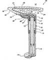
- FIG. 1is a side exploded view of the novel arm rest assembly
- FIG. 2is a side cross-sectional view of the novel arm rest assembly
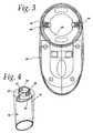
- FIG. 3is a bottom view of the lower arm pad assembly of the arm rest
- FIG. 4is a perspective exploded view of the shroud and arm support illustrating the circular detent-carrying device that is attached to the upper end of the shroud;
- FIG. 5is a perspective view of the novel arm rest assembly, the arm rest shown in the forward-facing position;
- FIG. 6is a side view of the arm chair assembly shown in FIG. 5;
- FIG. 7is a top view of the novel arm rest assembly illustrating rotation of 20° inwardly
- FIG. 8is a top view of the novel arm rest assembly showing a 20° rotation outwardly
- FIG. 9is a top view of the novel arm rest assembly illustrating the arm rest in the centered forward position
- FIG. 10is a side view of the novel arm rest assembly illustrating the arm rest assembly in its bottom position
- FIG. 11is a side view of a novel arm rest assembly illustrating the arm rest in its middle vertical position
- FIG. 12is a side view of a novel arm rest assembly illustrating the arm rest in its top or most elevated position.
- FIG. 1is an exploded side view of the novel height and pivot-adjusting office chair arm assembly 10 . It has an arm support 12 having one end 14 (shown in FIG. 2) for attaching the arm chair assembly 10 to a chair and having an opposite end 15 .
- a gas cylinder 22is placed within the arm support 12 for movement in the vertical direction to raise and lower arm rest 20 to any selected vertical position.
- a shroud 16surrounds and is vertically movable in relation to at least a portion of the arm support 12 .
- the shroud 16has an upper end 17 .
- the shroud 16is connected to the gas cylinder 22 with a press-fit for vertical movement by the gas cylinder.
- an arm rest support plate 18is attached only to the shroud with the bolts 19 for receiving the arm rest assembly 20 and enabling the arm rest assembly 20 to pivot in a horizontal plane thereby allowing the arm rest assembly 20 to assume any selected rotational position.
- the shroud 16comprises a hollow tube for slidably receiving the arm support 12
- FIG. 4has an ovate cross-sectional shape that conforms to the cross-sectional shape of the arm support 12 and is such that the shroud can move vertically with respect to the arm support 12 but is non-rotatable with respect to the arm support 12 .
- the cross-sectional shape of shroud 16 and the arm support 12could be of any shape other than cylindrical so that the shroud can move vertically with respect to the arm support but cannot be rotated.
- the ovate shapeis preferred.
- the arm rest assembly 20comprises an upper arm pad assembly 28 for receiving the arm of the user and a lower pad assembly 30 having a first end 32 attached to the upper arm pad assembly 28 , and a second end 34 attached to the arm rest pivot support 18 .
- a detent means 36best shown in FIG. 4, the upper end 17 of the shroud 16 to assist in holding the arm rest assembly 20 in a given horizontal rotational position.
- the lower arm pad assembly 30has at least one bearing and spring assembly 40 , best shown in FIG.
- a plurality of vertically-oriented detents 42are located in the shroud 36 and at least one bearing and spring assemblies, 40 , 44 on the lower arm pad assembly 30 such that each of the bearings 40 radially engages a different opposing detent 42 for releasably holding the arm rest assembly 20 in the given rotational position.
- the bearingsare ball bearings biased radially against elongated vertically-positioned detents 42 by springs 44 .
- roller bearingscould be used as the bearings 40 .
- At least two sets of three detents 42are disposed on diametrically-opposed sides of the detent-carrying device 36 .
- Each of the at least two bearings 40radially and releasably engage a corresponding set of detents 42 by means of the springs 44 shown in FIG. 3 .
- the detent-carrying device 36is circular in shape and has an outer periphery 37 for carrying the vertically-positioned detents 42 . Also as can be seen in FIG.
- the bearing and spring assemblies 40 , 44are spaced from each other with each of the bearings 40 releasably and radially engaging corresponding detents 42 and enabling the arm rest assembly 20 to assume any selected horizontal position represented by the detents 42 . It can be seen that since the bearings roll against the outer periphery of the shroud 16 in a bearing race 52 , that the detent-carrying device 36 allows 40° rotation of the arm rest assembly 20 .
- the arm rest assembly 20has a substantially V-shaped arm pad assembly having a first leg 28 and second leg 30 joined at the one end 32 .
- the first leg 28forms a substantially-horizontal upper rest for the user's arm
- the second leg 30is a lower rest for attachment to the upper end 17 of the shroud 16 .
- the first leg 28is longer than the second leg 30 .
- the second leg 30is at least partially hollow.
- a lever actuator 46extends from the hollow portion of the second leg 30 with a lever 48 extending through the partially-hollow second leg 30 between the lever actuator 46 and the gas cylinder 22 such that the lever actuator 46 can be used to move the lever 48 to actuate the gas cylinder 22 and in a well-known manner and enable raising and lowering of the aim rest assembly 20 .
- FIG. 3is a bottom view of the lower arm pad assembly 30 taken along line 3 — 3 in FIG. 1 .
- a novel height and pivot-adjustable arm rest assembly 20 for a chaircomprising a hollow main arm support 12 for rigid attachment to the chair at 14 ; a gas cylinder 22 in the hollow main support arm 12 for raising and lowering the arm rest assembly 20 ; a hollow housing or shroud 16 surrounding the hollow main arm support 12 for relative, slidable motion in the vertical direction and having an upper portion 17 attached to the upper end of the gas cylinder preferably by a press-fit for movement therewith; a circular detent means 36 mounted on the upper portion 17 of the hollow housing or shroud 16 for establishing arcuate arm rest positions; an arm pad assembly 20 forming a portion of the arm rest assembly 10 for rigid to the upper portion 17 of the hollow shroud 16 ; and a radially-biased bearing and spring assembly 40 associated with the lower second leg 30 for engaging detents 42 in the circular detent means 36 such that the arm rest assembly 20 may be rotated to any desired arm rest position and releasably held in place by the bearing and
- Both the hollow main arm support 12 and the hollow housing 16have corresponding cross-sectional shapes that prevent rotation of the housing 16 with respect to the main arm support 12 , but allows relative vertical movement of the housing 16 with respect to the main arm support 12 .
- the bearings 40are roller bearings in a bearing cage 52 with the long bearing axis in the vertical plane for radially engaging the detents to releasably hold the arm rest assembly 20 in the given rotated position.
- the bearingscould be ball bearings in bearing cage 52 for radially engaging the detents 42 to releasably hold the arm rest assembly in the given rotated position.
- FIG. 5is a perspective view of the novel office chair arm assembly 10 with the arm rest assembly 20 being centered and pointing in the forward direction.
- FIG. 6is a side view of the office chair arm assembly 10 shown in FIG. 5 .
- FIGS. 7, 8 and 9illustrate, respectively, a top view of the office chair assembly 10 with the arm rest assembly 20 rotated 20° inwardly, 20° outwardly, and centered.
- FIGS. 10, 11 and 12are side views of the novel office chair arm assembly 10 illustrating the arm rest assembly 20 in the lowest, the middle, and the highest arm rest positions.
Landscapes
- Chairs Characterized By Structure (AREA)
Abstract
Description
1. Field of the Invention
The present invention relates in general to an office chair arm rest and in particular to an office chair arm rest that can be adjusted in height and rotation about a vertical axis.
2. Description of Related Art Including Information Disclosed Under 37 C.F.R. §§1.97 and 1.98
There are many different patents disclosing chair arm rests that can be adjusted vertically in height and rotationally in a horizontal plane to conform to the arms of the user of the chair.
Some of these patents disclose hydraulic actuators for raising and lowering the arm rest, such as U.S. Pat. Nos. 5,931,536; 5,908,221; and 5,765,804.
Others disclose some manually-activated support shafts that can be manually raised and lowered with some type of engaging device. Some of such patents are U.S. Pat. Nos. 5,393,124; 5,971,484; 6,053,578; 5,895,095; 5,749,628; 5,641,203; 5,647,638; and 5,407,249.
Other patents disclose strictly horizontally-adjustable arm rests such as disclosed in U.S. Pat. Nos. 5,590,934; 5,655,814; 5,884,976; 5,944,486; and 6,045,191.
All of these patents disclose complex mechanisms for raising and lowering the arm rest and for pivoting the arm rest in a horizontal plane.
It would be in a desirable to have an arm rest that can be moved both in the vertical plane and rotated horizontally with simple mechanisms that are easily constructed and easily usable.
The present invention relates to a height and pivot-adjustable office chair arm assembly that is operated vertically to provide different arm rest heights using a gas cylinder and is rotated in a horizontal plane about a vertical axis using a simple radially-biased ball bearing and detent assembly that is operable independent of the mechanism for raising and lowering the chair arm rest.
The chair arm assembly has an arm rest assembly thereon and comprises an arm support having one end for attaching the chair arm assembly to a chair and having an opposite end. A gas cylinder cooperates with the arm support for movement in the vertical direction to raise and lower the arm rest assembly to any selected vertical position. A shroud surrounds and vertically moves in relation to at least a portion of the arm support and has an upper end. The shroud is connected to the gas cylinder for vertical movement by the gas cylinder and an arm rest pivot support attached only to the shroud receives the arm rest assembly and enables the arm rest assembly to pivot in a horizontal plane thereby allowing the arm rest to assume a selected rotational position independent of the operation of the gas cylinder mechanism.
The shroud is formed of a hollow tube that slidedly receives the arm support. It has a cross-sectional shape that conforms to the cross-sectional shape of the arm support and is such that the shroud can move vertically with respect to arm support but is non-rotatable with respect to the arm support. In the preferred embodiment, the cross-sectional shape of the shroud and the arm support are ovate.
The arm rest assembly itself has an upper arm pad assembly for receiving the arm of the user, and a lower arm pad assembly that has a first end attached to the upper arm pad assembly, and a second end having a bearing and ring assembly that is associated with the arm rest pivot support that is attached only to the shroud. There is a detent carrying device fixedly attached to the lower end of the shroud to mate with the bearing support ring and assist in holding the arm rest in a given horizontal rotational position. The detent carrying device matingly engages the at least one bearing and spring assembly to enable the bearing to rotatively move from one detent to another as the arm rest pivot support plate is rotated about a substantially vertical axis to establish a given rotational position of the arm rest.
The novel detent-carrying device has a plurality of vertically-oriented detents and there are at least one bearing and spring assembly on the lower arm pad assembly such that each of the bearings radially engages a different one of the detents for releasably holding the arm rest in a given rotational position. In the preferred embodiment, the bearings are ball bearings biased radially against elongated vertically-positioned detents by springs or other resilient devices. The bearings could also be roller bearings that would also be biased radially against the detents by the springs. In the preferred embodiment, at least two sets of three detents are disposed on diametrically-opposed sides of the shroud, and each of the at least two bearings radially and releasably engages a corresponding set of detents. The top of the shroud is circular with an outer periphery for carrying the vertically-oriented detents. The bearing and spring assemblies are spaced from each other with each of the bearings releasably and radially engaging corresponding detents and enabling the arm rest assembly to assume any selected horizontal position represented by the detents. In the preferred embodiments, the detents allow 40° rotation of the arm rest assembly.
Further, the novel arm rest assembly comprises a substantially V-shaped arm pad assembly having first and second legs joined at one end. The first leg forms a substantially-horizontal upper rest for the user's arm, and the second leg is a lower rest for attachment for the shroud upper end, and the first leg is longer than the second leg.
In the preferred embodiment, the second leg is at least partially hollow with a lever actuator extending from the hollow portion of the second leg engaging and operating a lever extending through the partially-hollow second leg between the lever actuator and the gas cylinder such that the lever actuator can be used to move the lever to actuate the gas cylinder and enable raising and lowering of the arm rest assembly.
Thus, it is an object of the present invention to provide an arm rest for a chair that can be adjusted both vertically and rotationally in the horizontal plane about the vertical axis for adapting to a particular user.
It is also an object of the present invention to provide an arm rest assembly that is adjustable in the vertical direction with the use of a gas cylinder, and in the horizontal rotational position by a bearing radially biased against the detent assembly.
It is still another object of the present invention to provide a chair arm rest assembly that is movable in a vertical direction with a gas cylinder having an upper end attached to a shroud surrounding an arm support in which the gas cylinder can move vertically with the cross-sectional shape of the shroud and the arm support being such that the shroud can move vertically with respect to the arm support but cannot be rotated.
It is another object of the present invention to provide the shroud and the arm support with a cross-sectional ovate shape to allow sliding vertical relative motion but to prevent horizontal rotation with respect to each other.
It is also an object of the present invention to provide an arm rest assembly that has substantially V-shaped arm pad assembly having first and second legs joined at one end with the first leg forming a substantially-horizontal upper rest for the user's arm and the second leg forming a lower rest for attachment to the shroud upper end with the first leg being longer than the second leg.
Thus, the present invention relates to a height and pivot-adjustable office chair arm assembly having an arm rest assembly thereon and comprising an arm rest support having one end for attaching the chair arm assembly to a chair and having an opposite end; a gas cylinder cooperating with the arm rest support for movement in the vertical direction to raise and lower the arm rest support to any selected vertical position; a shroud surrounding and vertically movable in relation to at least a portion of the arm support and having an upper end; the shroud being connected to the upper end of the gas cylinder for vertical movement; and an arm rest pivot support attached only to the shroud for receiving the arm rest assembly and enabling the arm rest assembly to pivot in a horizontal plane thereby allowing the arm rest assembly to assume any selected rotational position.
These and other objects of the present invention will be more fully described when taken in conjunction with the following detailed description of the drawings wherein like numerals represent like elements and wherein:
FIG. 1 is a side exploded view of the novel arm rest assembly;
FIG. 2 is a side cross-sectional view of the novel arm rest assembly;
FIG. 3 is a bottom view of the lower arm pad assembly of the arm rest;
FIG. 4 is a perspective exploded view of the shroud and arm support illustrating the circular detent-carrying device that is attached to the upper end of the shroud;
FIG. 5 is a perspective view of the novel arm rest assembly, the arm rest shown in the forward-facing position;
FIG. 6 is a side view of the arm chair assembly shown in FIG. 5;
FIG. 7 is a top view of the novel arm rest assembly illustrating rotation of 20° inwardly;
FIG. 8 is a top view of the novel arm rest assembly showing a 20° rotation outwardly;
FIG. 9 is a top view of the novel arm rest assembly illustrating the arm rest in the centered forward position;
FIG. 10 is a side view of the novel arm rest assembly illustrating the arm rest assembly in its bottom position;
FIG. 11 is a side view of a novel arm rest assembly illustrating the arm rest in its middle vertical position; and
FIG. 12 is a side view of a novel arm rest assembly illustrating the arm rest in its top or most elevated position.
FIG. 1 is an exploded side view of the novel height and pivot-adjusting officechair arm assembly 10. It has anarm support 12 having one end14 (shown in FIG. 2) for attaching thearm chair assembly 10 to a chair and having anopposite end 15. Agas cylinder 22 is placed within thearm support 12 for movement in the vertical direction to raise and lowerarm rest 20 to any selected vertical position. Ashroud 16 surrounds and is vertically movable in relation to at least a portion of thearm support 12. Theshroud 16 has anupper end 17. Theshroud 16 is connected to thegas cylinder 22 with a press-fit for vertical movement by the gas cylinder. An armrest support plate 18 is attached only to the shroud with thebolts 19 for receiving thearm rest assembly 20 and enabling thearm rest assembly 20 to pivot in a horizontal plane thereby allowing thearm rest assembly 20 to assume any selected rotational position. It can be seen in FIGS. 2 and 4 that theshroud 16 comprises a hollow tube for slidably receiving thearm support 12, and as can best be seen in FIG. 4 has an ovate cross-sectional shape that conforms to the cross-sectional shape of thearm support 12 and is such that the shroud can move vertically with respect to thearm support 12 but is non-rotatable with respect to thearm support 12. Obviously, the cross-sectional shape ofshroud 16 and thearm support 12 could be of any shape other than cylindrical so that the shroud can move vertically with respect to the arm support but cannot be rotated. The ovate shape is preferred. Thearm rest assembly 20 comprises an upperarm pad assembly 28 for receiving the arm of the user and alower pad assembly 30 having afirst end 32 attached to the upperarm pad assembly 28, and asecond end 34 attached to the armrest pivot support 18. A detent means36, best shown in FIG. 4, theupper end 17 of theshroud 16 to assist in holding thearm rest assembly 20 in a given horizontal rotational position. The lowerarm pad assembly 30 has at least one bearing andspring assembly 40, best shown in FIG. 3, for matingly engaging the detent means38 on theshroud 16 such that thebearing 40 may rotatively move from one detent means38 to another as the armrest pivot support 18 is rotated about a substantially-vertical axis to establish a given rotational position of thearm rest assembly 20.
As can be seen best in FIGS. 3 and 4, a plurality of vertically-orienteddetents 42 are located in theshroud 36 and at least one bearing and spring assemblies,40,44 on the lowerarm pad assembly 30 such that each of thebearings 40 radially engages a different opposingdetent 42 for releasably holding thearm rest assembly 20 in the given rotational position. As can be seen in FIGS. 3 and 4, in the preferred embodiment, the bearings are ball bearings biased radially against elongated vertically-positioneddetents 42 bysprings 44. Of course, roller bearings could be used as thebearings 40. As can be seen in FIG. 4, at least two sets of threedetents 42 are disposed on diametrically-opposed sides of the detent-carryingdevice 36. Each of the at least twobearings 40 radially and releasably engage a corresponding set ofdetents 42 by means of thesprings 44 shown in FIG.3. It can be seen in FIG. 4 that the detent-carryingdevice 36 is circular in shape and has anouter periphery 37 for carrying the vertically-positioneddetents 42. Also as can be seen in FIG. 3, the bearing andspring assemblies bearings 40 releasably and radially engagingcorresponding detents 42 and enabling thearm rest assembly 20 to assume any selected horizontal position represented by thedetents 42. It can be seen that since the bearings roll against the outer periphery of theshroud 16 in abearing race 52, that the detent-carryingdevice 36 allows 40° rotation of thearm rest assembly 20.
As can best be seen in FIGS. 1 and 2, thearm rest assembly 20 has a substantially V-shaped arm pad assembly having afirst leg 28 andsecond leg 30 joined at the oneend 32. Thefirst leg 28 forms a substantially-horizontal upper rest for the user's arm, and thesecond leg 30 is a lower rest for attachment to theupper end 17 of theshroud 16. It will be noted that thefirst leg 28 is longer than thesecond leg 30. It can also best be seen in FIG. 2 that thesecond leg 30 is at least partially hollow. Alever actuator 46 extends from the hollow portion of thesecond leg 30 with alever 48 extending through the partially-hollowsecond leg 30 between thelever actuator 46 and thegas cylinder 22 such that thelever actuator 46 can be used to move thelever 48 to actuate thegas cylinder 22 and in a well-known manner and enable raising and lowering of theaim rest assembly 20.
It will be noted that FIG. 3 is a bottom view of the lowerarm pad assembly 30 taken alongline 3—3 in FIG.1.
Thus, there has been disclosed a novel height and pivot-adjustablearm rest assembly 20 for a chair comprising a hollowmain arm support 12 for rigid attachment to the chair at14; agas cylinder 22 in the hollowmain support arm 12 for raising and lowering thearm rest assembly 20; a hollow housing orshroud 16 surrounding the hollowmain arm support 12 for relative, slidable motion in the vertical direction and having anupper portion 17 attached to the upper end of the gas cylinder preferably by a press-fit for movement therewith; a circular detent means36 mounted on theupper portion 17 of the hollow housing orshroud 16 for establishing arcuate arm rest positions; anarm pad assembly 20 forming a portion of thearm rest assembly 10 for rigid to theupper portion 17 of thehollow shroud 16; and a radially-biased bearing andspring assembly 40 associated with the lowersecond leg 30 for engagingdetents 42 in the circular detent means36 such that thearm rest assembly 20 may be rotated to any desired arm rest position and releasably held in place by the bearing andspring assembly
Both the hollowmain arm support 12 and thehollow housing 16 have corresponding cross-sectional shapes that prevent rotation of thehousing 16 with respect to themain arm support 12, but allows relative vertical movement of thehousing 16 with respect to themain arm support 12.
In one preferred embodiment, thebearings 40 are roller bearings in a bearingcage 52 with the long bearing axis in the vertical plane for radially engaging the detents to releasably hold thearm rest assembly 20 in the given rotated position. The bearings could be ball bearings in bearingcage 52 for radially engaging thedetents 42 to releasably hold the arm rest assembly in the given rotated position.
FIG. 5 is a perspective view of the novel officechair arm assembly 10 with thearm rest assembly 20 being centered and pointing in the forward direction.
FIG. 6 is a side view of the officechair arm assembly 10 shown in FIG.5.
FIGS. 7,8 and9 illustrate, respectively, a top view of theoffice chair assembly 10 with thearm rest assembly 20 rotated 20° inwardly, 20° outwardly, and centered.
FIGS. 10,11 and12 are side views of the novel officechair arm assembly 10 illustrating thearm rest assembly 20 in the lowest, the middle, and the highest arm rest positions.
While the present invention has been described as in connection with a preferred embodiment thereof, it will be apparent to those skilled in the art that many changes and modifications can be made without departing from the spirit and scope of the invention. Accordingly, it is intended by the appended claims to cover all such changes and modifications encompassed by the spirit and scope of the appended claims.
Claims (16)
1. A height and pivotal adjustable office chair arm assembly having an arm rest assembly thereon and comprising:
an arm support having one end for attaching the arm chair assembly to a chair and having an opposite end;
a gas cylinder associated with said arm support for movement in the vertical direction to raise and lower the arm rest assembly to any selected vertical position;
a shroud surrounding, and vertically removable in relation to, at least a portion of said arm support and having an upper end;
said shroud being connected to said gas cylinder for vertical movement by said cylinder;
an arm rest pivot support attached only to said shroud for receiving said arm rest assembly and enabling said arm rest assembly to pivot in the horizontal plane, thereby allowing said arm rest assembly to assume any selected rotational position;
a hollow tube for slidably receiving said arm support; and
a cross-sectional shape that conforms to the cross-sectional shape of the arm support and being such that the shroud can move vertically with respect to the arm support but is non-rotatable with respect to the arm support.
2. The assembly ofclaim 1 wherein said shroud and arm support both have an ovate cross-sectional shape.
3. A height and pivotal adjustable office chair arm assembly having an arm rest assembly thereon and comprising:
an arm support having one end for attaching the arm chair assembly to a chair and having an opposite end;
a gas cylinder associated with said arm support for movement in the vertical direction to raise and lower the arm rest assembly to any selected vertical position;
a shroud surrounding, and vertically removable in relation to, at least a portion of said arm support and having an upper end;
said shroud being connected to said gas cylinder for vertical movement by said cylinder;
an arm rest pivot support attached only to said shroud for receiving said arm rest assembly and enabling said arm rest assembly to pivot in the horizontal plane, thereby allowing said arm rest assembly to assume any selected rotational position;
an upper arm pad assembly for receiving the arm of the user; and
a lower arm pad assembly having a first end attached to the upper arm pad assembly and having a second end for mating with the arm rest support and shroud.
4. The assembly ofclaim 3 further comprising:
a detent means carried by the upper end of said shroud to assist in holding the arm rest in a given horizontal rotational position; and
said lower arm pad assembly having at least one bearing and spring assembly for matingly engaging the detent means on the shroud such that the bearing may rotatably move from one detent to another as said arm rest pivot support is rotated about a substantially-vertical axis to establish a given rotational position of said arm rest assembly.
5. The assembly ofclaim 4 further comprising:
a plurality of vertically-oriented detents in said shroud; and
at least one bearing and spring assembly on said lower arm pad assembly such that each of said bearings radially engages a different one of said detents for releasably holding said arm rest assembly in said given rotational position.
6. The assembly ofclaim 5 wherein said bearings are elongated roller bearings biased radially against elongated vertically-positioned detents by said springs.
7. The assembly ofclaim 5 wherein said bearings are ball bearings biased radially against said detents by said springs.
8. The assembly ofclaim 5 further comprising:
at least two sets of three detents, each of said sets disposing on diametrically-opposed sides of said shroud; and
said at least one bearing radially and releasably engaging a corresponding set of detents.
9. The assembly ofclaim 5 further comprising:
a circular detent means having an outer periphery for carrying said vertically-oriented detents; and
said bearing and spring assemblies being spaced from each other with each of said bearings releasably and radially engaging corresponding detents and enabling said arm rest assembly to assume any selected horizontal position represented by said detents.
10. The assembly ofclaim 9 wherein said detents allow 40° rotation of said arm rest assembly.
11. A height and pivotal adjustable office chair arm assembly having an arm rest assembly thereon and comprising:
an arm support having one end for attaching the arm chair assembly to a chair and having an opposite end;
a gas cylinder associated with said arm support for movement in the vertical direction to raise and lower the arm rest assembly to any selected vertical position;
a shroud surrounding, and vertically removable in relation to, at least a portion of said arm support and having an upper end;
said shroud being connected to said gas cylinder for vertical movement by said cylinder;
an arm rest pivot support attached only to said shroud for receiving said arm rest assembly and enabling said arm rest assembly to pivot in the horizontal plane, thereby allowing said arm rest assembly to assume any selected rotational position;
a substantially V-shaped arm pad assembly having first and second legs joined at one end;
said first leg forming a substantially horizontal upper rest for the user's arm; and
said second leg being a lower rest for attachment to said shroud upper end; and
said first leg being longer than said second leg.
12. The assembly ofclaim 11 wherein:
said second leg is at least partially hollow;
a lever actuator extending from the hollow portion of said second leg; and
a lever extending through said partially hollow second leg between said lever actuator and said gas cylinder such that said lever actuator can be used to move said lever to actuate said gas cylinder and enable raising and lowering of said arm rest assembly.
13. The assembly as inclaim 12 wherein both a hollow main arm support and the shroud have corresponding cross-sectional shapes that prevent rotation of said shroud with respect to said main arm support that allows relative vertical movement of said shroud with respect to said main arm support.
14. The assembly ofclaim 13 wherein said bearings are roller bearings in a bearing cage with a long bearing axis in the vertical plane for radially engaging said detents to releasably hold said arm rest assembly in a given located position.
15. The assembly ofclaim 13 wherein said bearings are ball bearings in a bearing cage for radially engaging said detents to releasably hold said arm rest assembly in a given rotated position.
16. An adjustable office chair arm assembly comprising:
an arm support having one end for attaching to a chair and a generally upstanding opposite end with a central opening and an outer surface;
structural elements located within said central opening for adjusting the vertical height of an attached armrest to one of a plurality of vertical positions;
a shroud surrounding at least a portion of said outer surface of said arm support, said shroud vertically movable relative to said arm support, said shroud being connected to said structural elements for being moved vertically, and said shroud having a flange, said flange having a plurality of detents; and
an armrest pivot support attached only to said shroud and pivotable independently of the vertical height of said shroud, said armrest pivot support having movable structural elements to engage said detents thereby allowing said armrest assembly to assume one of a plurality of rotational positions; and wherein
said flange is cylindrical in form and said detents are vertically positioned; and
said structural elements of said armrest pivot support are horizontally movable, spring biased balls.
Priority Applications (2)
| Application Number | Priority Date | Filing Date | Title |
|---|---|---|---|
| US09/881,818US6702386B2 (en) | 2001-06-15 | 2001-06-15 | Height and pivot-adjustable chair arm |
| US10/077,073US6773072B2 (en) | 2001-06-15 | 2002-02-15 | Vertically and horizontally adjustable chair armrest |
Applications Claiming Priority (1)
| Application Number | Priority Date | Filing Date | Title |
|---|---|---|---|
| US09/881,818US6702386B2 (en) | 2001-06-15 | 2001-06-15 | Height and pivot-adjustable chair arm |
Related Child Applications (1)
| Application Number | Title | Priority Date | Filing Date |
|---|---|---|---|
| US10/077,073Continuation-In-PartUS6773072B2 (en) | 2001-06-15 | 2002-02-15 | Vertically and horizontally adjustable chair armrest |
Publications (2)
| Publication Number | Publication Date |
|---|---|
| US20030042782A1 US20030042782A1 (en) | 2003-03-06 |
| US6702386B2true US6702386B2 (en) | 2004-03-09 |
Family
ID=25379285
Family Applications (1)
| Application Number | Title | Priority Date | Filing Date |
|---|---|---|---|
| US09/881,818Expired - LifetimeUS6702386B2 (en) | 2001-06-15 | 2001-06-15 | Height and pivot-adjustable chair arm |
Country Status (1)
| Country | Link |
|---|---|
| US (1) | US6702386B2 (en) |
Cited By (19)
| Publication number | Priority date | Publication date | Assignee | Title |
|---|---|---|---|---|
| US20040095008A1 (en)* | 2002-11-18 | 2004-05-20 | Marini Conrad M. | Armrest support |
| US6824217B1 (en)* | 2003-06-02 | 2004-11-30 | Fu Luong Hi-Tech Co., Ltd. | Height adjustable armrest assembly for a chair |
| US20060006723A1 (en)* | 2004-07-07 | 2006-01-12 | Humanscale Corporation | Ergonomic chair arm |
| US7011371B1 (en)* | 2004-11-29 | 2006-03-14 | Po-Chuan Tsai | Armrest assembly having a height adjustable function |
| USD539577S1 (en)* | 2006-04-17 | 2007-04-03 | True Seating Concepts, Llc | Chair arm |
| US20070085402A1 (en)* | 2005-10-03 | 2007-04-19 | Kimro2 International Ltd. | Adjustable armrest assembly |
| US20070278838A1 (en)* | 2006-06-02 | 2007-12-06 | Davis Judy G | Armrest |
| US20070284930A1 (en)* | 2006-06-09 | 2007-12-13 | Christianson Nicholas M | Chair having removable back or seat cushion assemblies and methods related thereto |
| USD572490S1 (en) | 2006-06-05 | 2008-07-08 | Steelcase Inc. | Chair |
| USD572914S1 (en) | 2006-06-05 | 2008-07-15 | Steelcase Inc. | Chair |
| USD576810S1 (en) | 2007-06-08 | 2008-09-16 | Cramer Inc. | Chair assembly |
| USD576809S1 (en) | 2007-06-08 | 2008-09-16 | Cramer Inc. | Chair assembly |
| US7490910B1 (en) | 2007-08-17 | 2009-02-17 | Roman Draughon | Adjustable pneumatic armrest for a chair |
| US20110254340A1 (en)* | 2010-04-20 | 2011-10-20 | Tsai Hsuan-Chin | Reversing Assembly for Office Chair Armrest |
| US8840188B2 (en) | 2004-07-07 | 2014-09-23 | Humanscale Corporation | Movable arm pad |
| US9592757B2 (en) | 2014-04-17 | 2017-03-14 | Hni Technologies Inc. | Armrest |
| US10165864B1 (en)* | 2017-06-16 | 2019-01-01 | Tung-Hua Su | Chair armrest device |
| US11589678B2 (en) | 2019-01-17 | 2023-02-28 | Hni Technologies Inc. | Chairs including flexible frames |
| WO2023211051A1 (en)* | 2022-04-25 | 2023-11-02 | 주식회사 시디즈 | Armrest assembly and chair comprising same |
Families Citing this family (4)
| Publication number | Priority date | Publication date | Assignee | Title |
|---|---|---|---|---|
| ITVI20030173A1 (en)* | 2003-09-11 | 2005-03-12 | Ares Line Srl | DEVICE FOR THE ADJUSTMENT AND, CONSEQUENTLY, OF THE HEIGHT OF THE ARMRESTS COMPARED TO THE PLAN OF THE SEAT OF A SESSION. |
| WO2008134801A1 (en)* | 2007-05-04 | 2008-11-13 | The Product People Pty Limited | Arm rest arrangement |
| US9844268B2 (en)* | 2015-03-16 | 2017-12-19 | Aaron DeJule | Sitting apparatus |
| US10131259B1 (en)* | 2017-07-14 | 2018-11-20 | Dae Won San Up Co., Ltd. | Armrest structure for vehicle seat |
Citations (22)
| Publication number | Priority date | Publication date | Assignee | Title |
|---|---|---|---|---|
| US4720068A (en)* | 1986-08-29 | 1988-01-19 | Tornero Lino E | Seat support column |
| US5393124A (en) | 1992-12-08 | 1995-02-28 | Neil; Gary K. | Armrest assembly |
| US5407249A (en) | 1990-10-15 | 1995-04-18 | Bonutti; Peter M. | Armrest assembly |
| US5497966A (en)* | 1992-04-11 | 1996-03-12 | Stabilus Gmbh | Column unit, in particular a chair column unit |
| US5590934A (en) | 1996-03-07 | 1997-01-07 | Shin Yeh Enterprise Co., Ltd. | Adjustable chair-armrest assembly |
| US5641203A (en) | 1995-06-07 | 1997-06-24 | Herman Miller Inc. | Adjustable arm rest assembly |
| US5647638A (en) | 1995-06-07 | 1997-07-15 | Haworth, Inc. | Height-adjustable chair arm assembly |
| US5655814A (en) | 1996-03-07 | 1997-08-12 | Shin Yeh Enterprise Co., Ltd. | Adjustable chair-armrest assembly |
| US5738318A (en)* | 1996-06-07 | 1998-04-14 | Haworth, Inc. | Chair with vertically shiftable height adjustment |
| US5749628A (en) | 1996-06-11 | 1998-05-12 | Fixtures Manufacturing Corporation | Vertically adjustable chair arm with rotatable armrest |
| US5765804A (en) | 1992-06-15 | 1998-06-16 | Herman Miller, Inc. | Pneumatic support colunm for a chair |
| US5884976A (en) | 1998-02-06 | 1999-03-23 | Nightingale Inc. | Chair swivel arm rest |
| US5895095A (en) | 1997-09-29 | 1999-04-20 | Chen; Su-Jan | Adjustable armrest assemblies for chairs |
| US5908221A (en) | 1997-06-09 | 1999-06-01 | Allseating Corporation | Vertically adjustable armrest assembly for a chair |
| US5931536A (en) | 1997-10-16 | 1999-08-03 | Wu; Yao-Chuan | Adjustable armrest of a chair |
| US5944386A (en) | 1998-02-13 | 1999-08-31 | Plus Corporation | Armrest device for chair |
| US5971484A (en) | 1997-12-03 | 1999-10-26 | Steelcase Development Inc. | Adjustable armrest for chairs |
| US6045191A (en)* | 1997-05-28 | 2000-04-04 | Desital Holland B.V. | Arm-rest for a chair and a chair comprising this arm-rest |
| US6053578A (en) | 1997-06-04 | 2000-04-25 | Knoll, Inc. | Multi-adjustable armrest assembly |
| US6076891A (en)* | 1997-11-17 | 2000-06-20 | Bernhardt; Sean E. | Dual-pivot multi-position ratcheting chair arm |
| US6079786A (en)* | 1997-05-07 | 2000-06-27 | Brunswick Corporation | One-shot pedestal swivel seat lock/release mechanism |
| US6345864B1 (en)* | 1999-09-09 | 2002-02-12 | Gloria Ramos Rivera | Adjustable support and retention device for interchangeable furnishings and/or equipment |
- 2001
- 2001-06-15USUS09/881,818patent/US6702386B2/ennot_activeExpired - Lifetime
Patent Citations (25)
| Publication number | Priority date | Publication date | Assignee | Title |
|---|---|---|---|---|
| US4720068A (en)* | 1986-08-29 | 1988-01-19 | Tornero Lino E | Seat support column |
| US5407249A (en) | 1990-10-15 | 1995-04-18 | Bonutti; Peter M. | Armrest assembly |
| US5497966A (en)* | 1992-04-11 | 1996-03-12 | Stabilus Gmbh | Column unit, in particular a chair column unit |
| US5765804A (en) | 1992-06-15 | 1998-06-16 | Herman Miller, Inc. | Pneumatic support colunm for a chair |
| US5393124A (en) | 1992-12-08 | 1995-02-28 | Neil; Gary K. | Armrest assembly |
| US5647638A (en) | 1995-06-07 | 1997-07-15 | Haworth, Inc. | Height-adjustable chair arm assembly |
| US5641203A (en) | 1995-06-07 | 1997-06-24 | Herman Miller Inc. | Adjustable arm rest assembly |
| US5853223A (en) | 1995-06-07 | 1998-12-29 | Haworth, Inc. | Height-adjustable chair arm assembly |
| US6106070A (en) | 1995-06-07 | 2000-08-22 | Haworth, Inc. | Height-adjustable chair arm assembly |
| US5655814A (en) | 1996-03-07 | 1997-08-12 | Shin Yeh Enterprise Co., Ltd. | Adjustable chair-armrest assembly |
| US5590934A (en) | 1996-03-07 | 1997-01-07 | Shin Yeh Enterprise Co., Ltd. | Adjustable chair-armrest assembly |
| US5738318A (en)* | 1996-06-07 | 1998-04-14 | Haworth, Inc. | Chair with vertically shiftable height adjustment |
| US5749628A (en) | 1996-06-11 | 1998-05-12 | Fixtures Manufacturing Corporation | Vertically adjustable chair arm with rotatable armrest |
| US6079786A (en)* | 1997-05-07 | 2000-06-27 | Brunswick Corporation | One-shot pedestal swivel seat lock/release mechanism |
| US6045191A (en)* | 1997-05-28 | 2000-04-04 | Desital Holland B.V. | Arm-rest for a chair and a chair comprising this arm-rest |
| US6053578A (en) | 1997-06-04 | 2000-04-25 | Knoll, Inc. | Multi-adjustable armrest assembly |
| US6076892A (en) | 1997-06-04 | 2000-06-20 | Knoll, Inc. | Multi-adjustable armrest assembly |
| US5908221A (en) | 1997-06-09 | 1999-06-01 | Allseating Corporation | Vertically adjustable armrest assembly for a chair |
| US5895095A (en) | 1997-09-29 | 1999-04-20 | Chen; Su-Jan | Adjustable armrest assemblies for chairs |
| US5931536A (en) | 1997-10-16 | 1999-08-03 | Wu; Yao-Chuan | Adjustable armrest of a chair |
| US6076891A (en)* | 1997-11-17 | 2000-06-20 | Bernhardt; Sean E. | Dual-pivot multi-position ratcheting chair arm |
| US5971484A (en) | 1997-12-03 | 1999-10-26 | Steelcase Development Inc. | Adjustable armrest for chairs |
| US5884976A (en) | 1998-02-06 | 1999-03-23 | Nightingale Inc. | Chair swivel arm rest |
| US5944386A (en) | 1998-02-13 | 1999-08-31 | Plus Corporation | Armrest device for chair |
| US6345864B1 (en)* | 1999-09-09 | 2002-02-12 | Gloria Ramos Rivera | Adjustable support and retention device for interchangeable furnishings and/or equipment |
Cited By (30)
| Publication number | Priority date | Publication date | Assignee | Title |
|---|---|---|---|---|
| US20040095008A1 (en)* | 2002-11-18 | 2004-05-20 | Marini Conrad M. | Armrest support |
| US6827406B2 (en)* | 2002-11-18 | 2004-12-07 | Conrad M. Marini | Armrest support |
| US6824217B1 (en)* | 2003-06-02 | 2004-11-30 | Fu Luong Hi-Tech Co., Ltd. | Height adjustable armrest assembly for a chair |
| US20040239170A1 (en)* | 2003-06-02 | 2004-12-02 | Fu Luong Hi-Tech Co., Ltd. | Height adjustable armrest assembly for a chair |
| US8840188B2 (en) | 2004-07-07 | 2014-09-23 | Humanscale Corporation | Movable arm pad |
| WO2006017065A2 (en) | 2004-07-07 | 2006-02-16 | Humanscale Corporation | Ergonomic chair arm |
| US20090015053A1 (en)* | 2004-07-07 | 2009-01-15 | Niels Diffrient | Ergonomic Chair Arm |
| US8104837B2 (en) | 2004-07-07 | 2012-01-31 | Humanscale Corporation | Ergonomic chair arm |
| EP1911370A2 (en) | 2004-07-07 | 2008-04-16 | Humanscale Corporation | Ergonomic chair arm |
| US20060006723A1 (en)* | 2004-07-07 | 2006-01-12 | Humanscale Corporation | Ergonomic chair arm |
| US7581791B2 (en) | 2004-07-07 | 2009-09-01 | Humanscale Corporation | Ergonomic chair arm |
| US7011371B1 (en)* | 2004-11-29 | 2006-03-14 | Po-Chuan Tsai | Armrest assembly having a height adjustable function |
| US20070085402A1 (en)* | 2005-10-03 | 2007-04-19 | Kimro2 International Ltd. | Adjustable armrest assembly |
| US7306288B2 (en)* | 2005-10-03 | 2007-12-11 | Kimro2 International Ltd. | Adjustable armrest assembly |
| USD539577S1 (en)* | 2006-04-17 | 2007-04-03 | True Seating Concepts, Llc | Chair arm |
| US7644991B2 (en) | 2006-06-02 | 2010-01-12 | Steelcase Inc. | Chair with folding armrest |
| US20070278838A1 (en)* | 2006-06-02 | 2007-12-06 | Davis Judy G | Armrest |
| USD572914S1 (en) | 2006-06-05 | 2008-07-15 | Steelcase Inc. | Chair |
| USD572490S1 (en) | 2006-06-05 | 2008-07-08 | Steelcase Inc. | Chair |
| US20070284930A1 (en)* | 2006-06-09 | 2007-12-13 | Christianson Nicholas M | Chair having removable back or seat cushion assemblies and methods related thereto |
| USD576810S1 (en) | 2007-06-08 | 2008-09-16 | Cramer Inc. | Chair assembly |
| USD576809S1 (en) | 2007-06-08 | 2008-09-16 | Cramer Inc. | Chair assembly |
| US7490910B1 (en) | 2007-08-17 | 2009-02-17 | Roman Draughon | Adjustable pneumatic armrest for a chair |
| US20090045664A1 (en)* | 2007-08-17 | 2009-02-19 | Roman Draughon | Adjustable pneumatic armrest for a chair |
| US20110254340A1 (en)* | 2010-04-20 | 2011-10-20 | Tsai Hsuan-Chin | Reversing Assembly for Office Chair Armrest |
| US9592757B2 (en) | 2014-04-17 | 2017-03-14 | Hni Technologies Inc. | Armrest |
| US10165864B1 (en)* | 2017-06-16 | 2019-01-01 | Tung-Hua Su | Chair armrest device |
| US11589678B2 (en) | 2019-01-17 | 2023-02-28 | Hni Technologies Inc. | Chairs including flexible frames |
| US12075921B2 (en) | 2019-01-17 | 2024-09-03 | Hni Technologies Inc. | Chairs including flexible frames |
| WO2023211051A1 (en)* | 2022-04-25 | 2023-11-02 | 주식회사 시디즈 | Armrest assembly and chair comprising same |
Also Published As
| Publication number | Publication date |
|---|---|
| US20030042782A1 (en) | 2003-03-06 |
Similar Documents
| Publication | Publication Date | Title |
|---|---|---|
| US6702386B2 (en) | Height and pivot-adjustable chair arm | |
| US6209958B1 (en) | Universal tilt mechanism for a chair | |
| US6920656B2 (en) | Height adjustable bed and automatic leg stabilizer system therefor | |
| US6176548B1 (en) | Tilt mechanism for chair having adjustable spring characteristics | |
| CA2680686C (en) | Adjustment device for a reclining chair | |
| EP3476255B1 (en) | Tiltable stool or lounge chair | |
| US7708347B2 (en) | Footrest mounting arrangement for an article of furniture | |
| WO2009157148A1 (en) | Rocking chair | |
| WO1996032989A1 (en) | Infant exercise device | |
| AU1127599A (en) | Adjustable supporting table | |
| US10932974B2 (en) | Adjustable bed systems with rotating articulating bed frame | |
| JPS6329644A (en) | Reclining chair frame | |
| EP2832265A1 (en) | Moveable seat | |
| EP0509693B1 (en) | Adjustable chair | |
| WO2019060215A1 (en) | Adjustable support legs for a mattress foundation | |
| EP3758557B1 (en) | Adjustable bed systems with rotating articulating bed frame | |
| CN109717652B (en) | Office chair structure with adjustable cushion inclination angle | |
| JP2002529198A (en) | Examination chair | |
| JP5774883B2 (en) | Medical table | |
| JP4217116B2 (en) | Seat slide mechanism | |
| KR20240166315A (en) | Attachable keyboard support structure | |
| CA2329376C (en) | Adjustable computer keyboard platform support mechanism | |
| JPH08317831A (en) | Shaft device with shaft having direction restituting function and elevatable function | |
| DK177688B1 (en) | Pivotable table device | |
| JPH0513231Y2 (en) |
Legal Events
| Date | Code | Title | Description |
|---|---|---|---|
| AS | Assignment | Owner name:HON TECHNOLOGY INC., IOWA Free format text:ASSIGNMENT OF ASSIGNORS INTEREST;ASSIGNOR:SCHOENFELDER, RODNEY C.;REEL/FRAME:012189/0921 Effective date:20010710 | |
| AS | Assignment | Owner name:HON TECHNOLOGY, INC., IOWA Free format text:ASSIGNMENT OF ASSIGNORS INTEREST;ASSIGNORS:DAVIS, KEITH L.;PHILLIPS, MATTHEW J.;REEL/FRAME:012190/0124 Effective date:20010709 | |
| STCF | Information on status: patent grant | Free format text:PATENTED CASE | |
| AS | Assignment | Owner name:HNI TECHNOLOGIES INC., IOWA Free format text:CHANGE OF NAME;ASSIGNOR:HON TECHNOLOGY INC.;REEL/FRAME:015908/0393 Effective date:20040511 | |
| FEPP | Fee payment procedure | Free format text:PAYOR NUMBER ASSIGNED (ORIGINAL EVENT CODE: ASPN); ENTITY STATUS OF PATENT OWNER: LARGE ENTITY | |
| FPAY | Fee payment | Year of fee payment:4 | |
| FPAY | Fee payment | Year of fee payment:8 | |
| FPAY | Fee payment | Year of fee payment:12 |