US6702347B1 - Integrated mounting system for the bumper, recovery rings and winch of a motor vehicle - Google Patents
Integrated mounting system for the bumper, recovery rings and winch of a motor vehicleDownload PDFInfo
- Publication number
- US6702347B1 US6702347B1US10/375,502US37550203AUS6702347B1US 6702347 B1US6702347 B1US 6702347B1US 37550203 AUS37550203 AUS 37550203AUS 6702347 B1US6702347 B1US 6702347B1
- Authority
- US
- United States
- Prior art keywords
- bracket
- bumper
- aperture
- plate
- mounting
- Prior art date
- Legal status (The legal status is an assumption and is not a legal conclusion. Google has not performed a legal analysis and makes no representation as to the accuracy of the status listed.)
- Expired - Fee Related
Links
- 238000011084recoveryMethods0.000titleclaimsabstractdescription32
- 238000009434installationMethods0.000description3
- 230000008859changeEffects0.000description2
- 230000004048modificationEffects0.000description2
- 238000012986modificationMethods0.000description2
- 230000006872improvementEffects0.000description1
- 238000011900installation processMethods0.000description1
- 230000013011matingEffects0.000description1
- 238000000034methodMethods0.000description1
- 238000005457optimizationMethods0.000description1
- 230000008569processEffects0.000description1
- 230000002787reinforcementEffects0.000description1
- 238000003466weldingMethods0.000description1
Images


Classifications
- B—PERFORMING OPERATIONS; TRANSPORTING
- B60—VEHICLES IN GENERAL
- B60D—VEHICLE CONNECTIONS
- B60D1/00—Traction couplings; Hitches; Draw-gear; Towing devices
- B60D1/48—Traction couplings; Hitches; Draw-gear; Towing devices characterised by the mounting
- B60D1/56—Traction couplings; Hitches; Draw-gear; Towing devices characterised by the mounting securing to the vehicle bumper
- B—PERFORMING OPERATIONS; TRANSPORTING
- B60—VEHICLES IN GENERAL
- B60D—VEHICLE CONNECTIONS
- B60D1/00—Traction couplings; Hitches; Draw-gear; Towing devices
- B60D1/14—Draw-gear or towing devices characterised by their type
- B60D1/18—Tow ropes, chains or the like
- B60D1/185—Tow ropes, chains or the like comprising a cable or chain winding device
- B—PERFORMING OPERATIONS; TRANSPORTING
- B60—VEHICLES IN GENERAL
- B60D—VEHICLE CONNECTIONS
- B60D1/00—Traction couplings; Hitches; Draw-gear; Towing devices
- B60D1/24—Traction couplings; Hitches; Draw-gear; Towing devices characterised by arrangements for particular functions
- B60D1/36—Traction couplings; Hitches; Draw-gear; Towing devices characterised by arrangements for particular functions for facilitating connection, e.g. hitch catchers, visual guide means, signalling aids
- B60D1/38—Traction couplings; Hitches; Draw-gear; Towing devices characterised by arrangements for particular functions for facilitating connection, e.g. hitch catchers, visual guide means, signalling aids involving auxiliary cables for drawing the trailer to the tractor before coupling
- B—PERFORMING OPERATIONS; TRANSPORTING
- B60—VEHICLES IN GENERAL
- B60D—VEHICLE CONNECTIONS
- B60D1/00—Traction couplings; Hitches; Draw-gear; Towing devices
- B60D1/48—Traction couplings; Hitches; Draw-gear; Towing devices characterised by the mounting
- B60D1/488—Traction couplings; Hitches; Draw-gear; Towing devices characterised by the mounting mounted directly to the chassis of the towing vehicle
- B—PERFORMING OPERATIONS; TRANSPORTING
- B60—VEHICLES IN GENERAL
- B60D—VEHICLE CONNECTIONS
- B60D1/00—Traction couplings; Hitches; Draw-gear; Towing devices
- B60D1/48—Traction couplings; Hitches; Draw-gear; Towing devices characterised by the mounting
- B60D1/56—Traction couplings; Hitches; Draw-gear; Towing devices characterised by the mounting securing to the vehicle bumper
- B60D1/565—Traction couplings; Hitches; Draw-gear; Towing devices characterised by the mounting securing to the vehicle bumper having an eyelet
- B—PERFORMING OPERATIONS; TRANSPORTING
- B60—VEHICLES IN GENERAL
- B60R—VEHICLES, VEHICLE FITTINGS, OR VEHICLE PARTS, NOT OTHERWISE PROVIDED FOR
- B60R19/00—Wheel guards; Radiator guards, e.g. grilles; Obstruction removers; Fittings damping bouncing force in collisions
- B60R19/02—Bumpers, i.e. impact receiving or absorbing members for protecting vehicles or fending off blows from other vehicles or objects
- B60R19/24—Arrangements for mounting bumpers on vehicles
- B—PERFORMING OPERATIONS; TRANSPORTING
- B60—VEHICLES IN GENERAL
- B60R—VEHICLES, VEHICLE FITTINGS, OR VEHICLE PARTS, NOT OTHERWISE PROVIDED FOR
- B60R19/00—Wheel guards; Radiator guards, e.g. grilles; Obstruction removers; Fittings damping bouncing force in collisions
- B60R19/02—Bumpers, i.e. impact receiving or absorbing members for protecting vehicles or fending off blows from other vehicles or objects
- B60R19/48—Bumpers, i.e. impact receiving or absorbing members for protecting vehicles or fending off blows from other vehicles or objects combined with, or convertible into, other devices or objects, e.g. bumpers combined with road brushes, bumpers convertible into beds
Definitions
- the present inventionrelates to motor vehicles, particularly pick-up trucks and sport utility vehicle motor vehicles. Still more particularly, the present invention relates to an integrated mounting system for mounting the front bumper, recovery rings and a selectively deployable winch to the frame of the aforementioned type of motor vehicle.
- bumpersare attached to the vehicle frame using a number of bolts and assorted brackets.
- Recovery ringshave become an essential part of an “off-road” package for motor vehicles. Recovery rings are utilized as anchor points for towing or vehicle recovery in the event the vehicle has become immobilized by an untoward driving incident (for example being stuck in a ditch).
- the recovery rings 110are pivotally connected to respective brackets 112 , which are, in turn, mounted to the left and right frame rails 114 L, 114 R of the vehicle frame 114 .
- Wincheshave been developed which are mechanically and electrically interfaced with a motor vehicle, for example to provide extrication from an immobilization caused by an untoward incident. Many experts advise motor vehicles that are used for off-road excursions be equipped with winches to provide self-recovery of the motor vehicle should an untoward event happen. The best location for a winch is the front of the motor vehicle.
- an improvement to motor vehicle winches 120is the utilization of a trailer hitch attachment 122 therefor which permits the winch to be stowed when not in use and easily deployed when needed.
- the winchhas a stinger 124 which is received into the square receptacle 126 of the trailer hitch 122 , and a pin 128 (held by a cotter pin 130 ) secures the placement of the stinger in the receptacle. Because winch strength can exceed recommended trailer hitch loads, the hitch utilized for winch purposes is usually more robust than a conventional trailer hitch.
- the trailer hitchis attached to the vehicle frame 114 via a special cross-member 132 which spans the left and right frame rails 114 L, 114 R.
- the attachment of the winch 120is via various brackets and reinforcements at a central location of the cross-member 132 , wherein the winch connects to the trailer hitch 122 at a location vertically below the bumper (not shown in FIG. 1 for clarity).
- the conventional trailer hitch winch attachment modalityinvolves an excessive amount of weight associated with the cross-member and the bracketry, and a low ground clearance and approach angle—all of which contributing to reduced road performance of a motor vehicle so equipped.
- the present inventionis an integrated mounting system for mounting the bumper, recovery rings and a selectively removable winch to the frame of a motor vehicle, wherein the system saves weight and improves both the ground clearance and the winch approach angle as compared to conventional mounting modalities.
- the integrated mounting systemincludes left and right mounting plates attached transversely to the front ends of the left and right frame rails of the motor vehicle frame wherein each mounting plate has a plate aperture, and left and right mounting brackets, each provided with a bracket aperture.
- the left and right mounting bracketseach have a planar base and a clevis perpendicularly upstanding in relation to the base. Attachment holes are provided in each of the left and right mounting plates and mounting brackets.
- the front bumperalso has a pair of bumper apertures and is also provided with attachment holes.
- the left and right mounting platesare welded to the front end, respectively, of each of the left and right frame rails.
- the rear surface of the front bumperis placed in abutting relation to the left and right mounting plates.
- the base of the left and right mounting bracketsis placed in respective direct alignment with the left and right mounting plates in abutment of the front surface of the bumper.
- the plate, bracket and bumper aperturesare aligned at each of the left and right frame rails, respectively.
- Boltsare now placed through the left and right mounting brackets, bumper and left and right mounting plates and nuts threadingly tightened thereunto, thereby simultaneously attaching to the motor vehicle frame the front bumper and mounts for recovery rings and a winch.
- a recovery ringis attached to each clevis, using a bolt and nut combination, or a pin and cotter pin combination.
- the userremoves a selected one of the recovery rings, and then places the stinger of the winch through the aligned bracket and plate apertures, and the bolt or pin of the recovery ring then placed through the clevis and a securement hole of the stinger to thereby hold the winch in place.
- the userthen connects the winch to an electrical connection and thereupon actuates the winch as needed, as for example to recover the motor vehicle for an untoward driving incident.
- the winchis stabilized relative to the frame rail at which it is located via a slidable, yet snug fit between the stinger with the two aligned and spaced apart plate and bracket apertures.
- the winchis removed and again stored; and the recovery ring is then reinstalled.
- FIG. 1is a perspective view of a prior art motor vehicle frame equipped with left and right recovery rings and trailer hitch mounted winch.
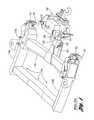
- FIG. 2is a perspective view of a motor vehicle frame, wherein the left and right frame rails are provided, respectively, with left and right mounting brackets.
- FIG. 3is a perspective view of a motor vehicle frame, wherein the left and right frame rails are provided, respectively, with left and right mounting brackets as in FIG. 2, but now the front bumper is located abuttingly thereat.
- FIG. 4Ais a perspective view of a mounting bracket according to the present invention.
- FIG. 4Bis a side view, seen along line 4 B— 4 B of FIG. 4 A.
- FIG. 5is a perspective view of a motor vehicle frame, wherein the left and right frame rails are provided, respectively, with left and right mounting brackets and the front bumper is located thereat as in FIGS. 2 and 3, wherein now left and right mounting brackets are attached, respectively to the left and right mounting brackets and bumper sandwiched therebetween.
- FIG. 6is a partly sectional side view, seen along line 6 — 6 of FIG. 5 .
- FIG. 7is a perspective view of a mounting bracket equipped with a recovery ring.
- FIG. 8is a partly sectional side view of a winch installed at a former recovery ring location according to the present invention.
- FIGS. 2 through 8depict the integrated mounting system 10 (see FIGS. 5 and 6) according to the present invention for mounting a front bumper 12 (see FIG. 3 ), recovery rings 14 (see FIGS. 5, 6 and 7 ) and a selectively removable winch 16 (see FIG. 8) to the motor vehicle frame 18 of a motor vehicle 20 .
- the motor vehicle frame 18has left and right frame rails 18 L, 18 R, each respectively having a front end 22 .
- a left and right-mounting plate 24 L, 24 Ris welded, respectively, in transverse relation to each of the left and right frame rails 18 L, 18 R at the front end 22 thereof.
- Each of the left and right mounting plates 24 L, 24 Rhas a plate aperture 26 .
- Attachment holes 28are provided in each of the left and right mounting plates 24 L, 24 R, one attachment hole being located at opposite sides of the plate aperture 26 .
- the plate apertures 26communicate with an open space S of the left and right frame rails 18 L, 18 R, which have a cross-sectional area C at least as large as the cross-sectional area of the plate apertures (see in particular FIG. 6 ).
- FIG. 3depicts the above referenced front bumper 12 now located for final installation.
- the front bumper 12has left and right mounting features 30 L, 30 R, wherein the rear side thereof abuts, respectively, the left and right mounting plates 24 L, 24 R.
- a bumper aperture 32is provided in each of the left and right mounting features 30 L, 30 R, and provided as well are a pair of attachment holes 34 , one attachment hole on each side of the bumper aperture.
- Each bumper aperture 32is the same size or a little larger than, the plate apertures 26 .
- the placement of the front bumper 12aligns, at each of the left and right frame rails 18 L, 18 R, the bumper and mounting plate apertures 32 , 26 , as well as aligns the attachment holes 34 , 28 associated respectively therewith.
- FIGS. 4A and 4Bdepict identical left and right mounting brackets 36 L, 36 R, each having a planar base 38 and a clevis 40 which is connected (as for example by welding) to the base in perpendicular upstanding relation thereto.
- a bracket aperture 42Between the projections 40 a , 40 b of the clevis 40 of each of the left and right mounting brackets 36 L, 36 R is formed a bracket aperture 42 , wherein the bracket apertures have identically the same dimensions as the plate apertures 26 .
- Attachment holes 44are provided in each of the left and right mounting brackets 32 L, 32 R, one attachment hole on either side of the bracket aperture 42 .
- Each of the projections 40 a , 40 b of the clevis 40has a mutually aligned mounting hole 46 .
- FIG. 6exemplifies how the front bumper 12 is finally installed, further to the locating thereof as depicted at FIG. 3 .
- the base 38 of each of the left and right mounting brackets 36 L, 36 Ris abutted to the outside surface of each of the left and right mounting features 30 L, 30 R, respectively.
- the bracket aperture 42 , the bumper aperture 32 and the plate aperture 26 respectively thereatare mutually aligned, and wherein the bolts holes 44 , 34 , 28 are simultaneously also mutually aligned.
- a fastenerpreferably a bolt 48
- a bolt 48is now placed through the aligned attachment holes 44 , 34 , 28 of the left and right mounting brackets 36 L, 36 R, the front bumper 12 and left and right mounting plates 24 L, 24 R and a nut 50 is threadingly tightened onto each of the bolts, respectively.
- this final installation stephas integrated the front bumper 12 to the motor vehicle frame 18 , while simultaneously providing mountings for recovery rings 14 and a winch 16 , as will be understood by further reference to the drawings at FIGS. 7 and 8.
- a recovery ring 14is attached to each clevis 40 , using a connector in the preferred form of a bolt and nut combination 52 (as shown at FIG. 7) or a pin and cotter pin combination (see 52 ′ at FIG. 8) passing through the mounting holes 46 of the clevis and through the ring holes 56 of the recovery rings and secures at outside of the ring holes to thereby pivotally attach the recovery ring to the clevis.
- the userremoves a selected one of the recovery rings 14 (depending on which side of the vehicle is more apt to provide winching success).
- the userplaces the stinger 58 of the winch through the aligned bracket, bumper and plate apertures 42 , 32 , 26 .
- the stinger 58has a securement hole 60 , and the connector 52 , 52 ′ (a pin and cotter pin combination being shown) of the (now removed) recovery ring is then placed through the mounting holes 46 of the clevis 40 and the securement hole to thereby securely hold the winch in place with respect to the vehicle frame 18 .
- the winch 16is stabilized relative to the selected left or right frame rail 18 L, 18 R of the motor vehicle frame 18 via a slidable, yet snug fit between the stinger 58 with the two aligned and spaced apart plate and bracket apertures 26 , 42 .
- the dimensions of the plate and bracket apertures 26 , 42are commensurate to the dimensions of the stinger 58 , as for example each having a mutually mating square cross-section.
- the userthen connects an electrical connector 62 of the winch 16 to an electrical connector 64 of the motor vehicle. Thereupon, the user actuates the winch 16 as needed, as for example to recover the motor vehicle for an untoward driving incident.
- the winch 16is removed and again stored; and the recovery ring 14 is then reinstalled using the bolt and nut combination or pin and cotter pin combination.
- the integrated mounting system 10provides a secure and sturdy connection of mounting rings and a winch with very little bracketing. Further, the installation process is facilitated, in that the front bumper is integrated into the mounting process. Since both the winch attachments afforded selectively at each of the left and right mounting brackets 36 L, 36 R are in line with the longitudinal frame rails 18 L, 18 R, the structure is inherently stronger than that of a center mounted trailer hitch winch connection, as depicted at FIG. 1, importantly with no mass addition penalty. Further, the present invention does not interfere with the approach angle of the motor vehicle, and thereby does not diminish the off road capability and performance of the motor vehicle. Because the winch 16 may be located at either of the left and right mounting brackets 36 L, 36 R, an increased winch optimization is provided in those situations in which space available for winch operation is confined.
Landscapes
- Engineering & Computer Science (AREA)
- Mechanical Engineering (AREA)
- Transportation (AREA)
- Body Structure For Vehicles (AREA)
Abstract
Description
Claims (6)
Priority Applications (1)
| Application Number | Priority Date | Filing Date | Title |
|---|---|---|---|
| US10/375,502US6702347B1 (en) | 2003-02-26 | 2003-02-26 | Integrated mounting system for the bumper, recovery rings and winch of a motor vehicle |
Applications Claiming Priority (1)
| Application Number | Priority Date | Filing Date | Title |
|---|---|---|---|
| US10/375,502US6702347B1 (en) | 2003-02-26 | 2003-02-26 | Integrated mounting system for the bumper, recovery rings and winch of a motor vehicle |
Publications (1)
| Publication Number | Publication Date |
|---|---|
| US6702347B1true US6702347B1 (en) | 2004-03-09 |
Family
ID=31888147
Family Applications (1)
| Application Number | Title | Priority Date | Filing Date |
|---|---|---|---|
| US10/375,502Expired - Fee RelatedUS6702347B1 (en) | 2003-02-26 | 2003-02-26 | Integrated mounting system for the bumper, recovery rings and winch of a motor vehicle |
Country Status (1)
| Country | Link |
|---|---|
| US (1) | US6702347B1 (en) |
Cited By (16)
| Publication number | Priority date | Publication date | Assignee | Title |
|---|---|---|---|---|
| US20050212311A1 (en)* | 2004-03-26 | 2005-09-29 | Aisin Seiki Kabushiki Kaisha | Bumper reinforcement for vehicle |
| EP1757488A3 (en)* | 2005-08-25 | 2007-04-04 | WESTFALIA - Automotive GmbH | Support structure for vehicle and corresponding holder assembly |
| US20080001383A1 (en)* | 2006-06-30 | 2008-01-03 | Aisin Seiki Kabushiki Kaisha | Towing hook mounting member and bumper mechanism with the same |
| US20080047985A1 (en)* | 2004-02-23 | 2008-02-28 | Newbill Anthony J | Tire cover for a spare tire carrier |
| WO2009034376A1 (en)* | 2007-09-11 | 2009-03-19 | Bae Systems Plc | Chassis |
| US7703834B1 (en)* | 2008-10-24 | 2010-04-27 | Omix-Ada, Inc. | Modular bumper system |
| US20100181786A1 (en)* | 2007-07-24 | 2010-07-22 | Mack Trucks, Inc. | Front Bumper Arrangement for a Truck For Single or Dual Tow Points |
| US8419116B2 (en) | 2010-07-08 | 2013-04-16 | Honda Motor Co., Ltd. | Vehicle frame assembly |
| CN103359170A (en)* | 2013-07-25 | 2013-10-23 | 长城汽车股份有限公司 | Frame and vehicle with frame |
| US8714592B1 (en) | 2013-09-12 | 2014-05-06 | Hendrick Motorsports Performance Group, LLC | System for securing a vehicle during transport against movement under forces from multiple directions |
| AU2009213134B2 (en)* | 2008-09-22 | 2015-05-28 | Bartlett Transport Improvements Pty. Ltd. | Towbar and method for manufacturing a towbar |
| US10065466B2 (en) | 2016-02-24 | 2018-09-04 | Ronald Lisby | Universal hitch system |
| US20190351721A1 (en)* | 2018-05-15 | 2019-11-21 | GM Global Technology Operations LLC | Trailer hitch integrated tow hook and step |
| CN111703261A (en)* | 2020-06-10 | 2020-09-25 | 北京汽车集团越野车有限公司 | Winch supporting structure with trailer ring and automobile |
| US11014517B2 (en)* | 2017-10-27 | 2021-05-25 | TAP Worldwide, LLC | Vehicle accessories |
| USD1097905S1 (en) | 2024-07-23 | 2025-10-14 | Phil Koenigs | Tow bar |
Citations (29)
| Publication number | Priority date | Publication date | Assignee | Title |
|---|---|---|---|---|
| US3740079A (en) | 1970-08-20 | 1973-06-19 | G Skinner | Vehicular towing hitch |
| US3754784A (en)* | 1971-11-26 | 1973-08-28 | Gen Motors Corp | Vehicle bumper mounting arrangement |
| US3794227A (en) | 1972-05-03 | 1974-02-26 | S Stearns | Bicycle carrier for vehicles |
| US3862669A (en)* | 1972-11-24 | 1975-01-28 | Gen Motors Corp | Occupant restraint system |
| US3880455A (en)* | 1972-03-14 | 1975-04-29 | Nils Christian Toemmeraas | Shock absorbing vehicle bumper assembly |
| US3881751A (en) | 1974-03-04 | 1975-05-06 | Raymond Lee Colby | Automatically stowable towline for vehicle |
| US3947062A (en)* | 1975-04-07 | 1976-03-30 | Harless Pierce | Vehicle bumper convertible to a tow bar |
| US4073508A (en)* | 1975-03-28 | 1978-02-14 | Jimmie George | Adjustable trailer hitch |
| US4230253A (en)* | 1978-10-11 | 1980-10-28 | The B. F. Goodrich Company | Method of making a caliper brake rotor |
| US4331323A (en)* | 1980-03-11 | 1982-05-25 | Toyota Jidosha Kogyo Kabushiki Kaisha | Electric winch system |
| US4646952A (en) | 1984-05-17 | 1987-03-03 | Timmers Richard E | Method and apparatus for carrying a load with a motor vehicle |
| US4738464A (en) | 1987-03-26 | 1988-04-19 | Putnam Manufacturing | Combined bumper and receiver trailer hitch assembly |
| US4753560A (en)* | 1985-11-07 | 1988-06-28 | Ryder International Corporation | Fastener-carrier system |
| US4809924A (en)* | 1987-07-20 | 1989-03-07 | Marvin Martens | Hydraulic bumper |
| US4829979A (en)* | 1987-11-27 | 1989-05-16 | Chrysler Motors Corporation | Impact absorbing device for a vehicle |
| US4950010A (en)* | 1989-06-19 | 1990-08-21 | Denny Gerald L | Vehicle frame-mountable accessory receiver apparatus and method for manufacture |
| US5433356A (en)* | 1993-07-12 | 1995-07-18 | Russell; Jay A. | Vise adapted for mounting to a trailer receiver by its inner member |
| US5560631A (en)* | 1995-06-02 | 1996-10-01 | Salvo; Ronald F. | Trailer hitch cover |
| US5595007A (en)* | 1994-11-29 | 1997-01-21 | Biance; Michael P. | Trailer-type snowplow |
| US5785367A (en)* | 1995-03-31 | 1998-07-28 | Mercedes-Benz Ag | Bumper |
| US5791633A (en) | 1997-03-11 | 1998-08-11 | Walker; Donald L. | Skid plate/winch mount |
| US5854832A (en)* | 1995-06-26 | 1998-12-29 | Rockwell International Corp. | Monitoring system and method used in automatic call distributor for timing incoming telephone calls |
| US5873595A (en)* | 1995-04-07 | 1999-02-23 | Hinte; Thomas M. | Tow bar assembly |
| US6364384B1 (en)* | 2000-12-14 | 2002-04-02 | Daimlerchrysler Corporation | Vehicle bumper concealment |
| US20020047281A1 (en)* | 2000-10-19 | 2002-04-25 | Benteler Automobiltechnik Gmbh & Co. Kg | Bumper arrangement |
| US20020047247A1 (en)* | 1999-10-29 | 2002-04-25 | Moss Newell Ryan | Stowaway, receiver hitch |
| US20020113447A1 (en)* | 2001-02-21 | 2002-08-22 | Alcan Technology & Management Ltd. | Vehicle with bumper and deformation element |
| US20020140206A1 (en)* | 2001-04-02 | 2002-10-03 | Lloyd Michael J. | Trailer hitch towing member adapter |
| US20030034661A1 (en)* | 2001-07-30 | 2003-02-20 | Terutsugu Gotanda | Bumper device for vehicles and bumper stay |
- 2003
- 2003-02-26USUS10/375,502patent/US6702347B1/ennot_activeExpired - Fee Related
Patent Citations (29)
| Publication number | Priority date | Publication date | Assignee | Title |
|---|---|---|---|---|
| US3740079A (en) | 1970-08-20 | 1973-06-19 | G Skinner | Vehicular towing hitch |
| US3754784A (en)* | 1971-11-26 | 1973-08-28 | Gen Motors Corp | Vehicle bumper mounting arrangement |
| US3880455A (en)* | 1972-03-14 | 1975-04-29 | Nils Christian Toemmeraas | Shock absorbing vehicle bumper assembly |
| US3794227A (en) | 1972-05-03 | 1974-02-26 | S Stearns | Bicycle carrier for vehicles |
| US3862669A (en)* | 1972-11-24 | 1975-01-28 | Gen Motors Corp | Occupant restraint system |
| US3881751A (en) | 1974-03-04 | 1975-05-06 | Raymond Lee Colby | Automatically stowable towline for vehicle |
| US4073508A (en)* | 1975-03-28 | 1978-02-14 | Jimmie George | Adjustable trailer hitch |
| US3947062A (en)* | 1975-04-07 | 1976-03-30 | Harless Pierce | Vehicle bumper convertible to a tow bar |
| US4230253A (en)* | 1978-10-11 | 1980-10-28 | The B. F. Goodrich Company | Method of making a caliper brake rotor |
| US4331323A (en)* | 1980-03-11 | 1982-05-25 | Toyota Jidosha Kogyo Kabushiki Kaisha | Electric winch system |
| US4646952A (en) | 1984-05-17 | 1987-03-03 | Timmers Richard E | Method and apparatus for carrying a load with a motor vehicle |
| US4753560A (en)* | 1985-11-07 | 1988-06-28 | Ryder International Corporation | Fastener-carrier system |
| US4738464A (en) | 1987-03-26 | 1988-04-19 | Putnam Manufacturing | Combined bumper and receiver trailer hitch assembly |
| US4809924A (en)* | 1987-07-20 | 1989-03-07 | Marvin Martens | Hydraulic bumper |
| US4829979A (en)* | 1987-11-27 | 1989-05-16 | Chrysler Motors Corporation | Impact absorbing device for a vehicle |
| US4950010A (en)* | 1989-06-19 | 1990-08-21 | Denny Gerald L | Vehicle frame-mountable accessory receiver apparatus and method for manufacture |
| US5433356A (en)* | 1993-07-12 | 1995-07-18 | Russell; Jay A. | Vise adapted for mounting to a trailer receiver by its inner member |
| US5595007A (en)* | 1994-11-29 | 1997-01-21 | Biance; Michael P. | Trailer-type snowplow |
| US5785367A (en)* | 1995-03-31 | 1998-07-28 | Mercedes-Benz Ag | Bumper |
| US5873595A (en)* | 1995-04-07 | 1999-02-23 | Hinte; Thomas M. | Tow bar assembly |
| US5560631A (en)* | 1995-06-02 | 1996-10-01 | Salvo; Ronald F. | Trailer hitch cover |
| US5854832A (en)* | 1995-06-26 | 1998-12-29 | Rockwell International Corp. | Monitoring system and method used in automatic call distributor for timing incoming telephone calls |
| US5791633A (en) | 1997-03-11 | 1998-08-11 | Walker; Donald L. | Skid plate/winch mount |
| US20020047247A1 (en)* | 1999-10-29 | 2002-04-25 | Moss Newell Ryan | Stowaway, receiver hitch |
| US20020047281A1 (en)* | 2000-10-19 | 2002-04-25 | Benteler Automobiltechnik Gmbh & Co. Kg | Bumper arrangement |
| US6364384B1 (en)* | 2000-12-14 | 2002-04-02 | Daimlerchrysler Corporation | Vehicle bumper concealment |
| US20020113447A1 (en)* | 2001-02-21 | 2002-08-22 | Alcan Technology & Management Ltd. | Vehicle with bumper and deformation element |
| US20020140206A1 (en)* | 2001-04-02 | 2002-10-03 | Lloyd Michael J. | Trailer hitch towing member adapter |
| US20030034661A1 (en)* | 2001-07-30 | 2003-02-20 | Terutsugu Gotanda | Bumper device for vehicles and bumper stay |
Cited By (24)
| Publication number | Priority date | Publication date | Assignee | Title |
|---|---|---|---|---|
| US20080047985A1 (en)* | 2004-02-23 | 2008-02-28 | Newbill Anthony J | Tire cover for a spare tire carrier |
| US20050212311A1 (en)* | 2004-03-26 | 2005-09-29 | Aisin Seiki Kabushiki Kaisha | Bumper reinforcement for vehicle |
| US7137658B2 (en)* | 2004-03-26 | 2006-11-21 | Aisin Seiki Kabushiki Kaisha | Bumper reinforcement for vehicle |
| EP1757488A3 (en)* | 2005-08-25 | 2007-04-04 | WESTFALIA - Automotive GmbH | Support structure for vehicle and corresponding holder assembly |
| EP2266842A3 (en)* | 2005-08-25 | 2011-04-06 | WESTFALIA - Automotive GmbH | Support structure for vehicle and corresponding holder assembly |
| EP2284042A3 (en)* | 2005-08-25 | 2011-04-06 | WESTFALIA - Automotive GmbH | Support structure for vehicle and corresponding holder assembly |
| US20080001383A1 (en)* | 2006-06-30 | 2008-01-03 | Aisin Seiki Kabushiki Kaisha | Towing hook mounting member and bumper mechanism with the same |
| US8308184B2 (en)* | 2006-06-30 | 2012-11-13 | Aisin Seiki Kabushiki Kaisha | Towing hook mounting member and bumper mechanism with the same |
| US20100181786A1 (en)* | 2007-07-24 | 2010-07-22 | Mack Trucks, Inc. | Front Bumper Arrangement for a Truck For Single or Dual Tow Points |
| US8322763B2 (en) | 2007-07-24 | 2012-12-04 | Mack Trucks, Inc. | Front bumper arrangement for a truck for single or dual tow points |
| US20100170739A1 (en)* | 2007-09-11 | 2010-07-08 | Bae Systems Plc | Chassis |
| WO2009034376A1 (en)* | 2007-09-11 | 2009-03-19 | Bae Systems Plc | Chassis |
| AU2009213134B2 (en)* | 2008-09-22 | 2015-05-28 | Bartlett Transport Improvements Pty. Ltd. | Towbar and method for manufacturing a towbar |
| US7703834B1 (en)* | 2008-10-24 | 2010-04-27 | Omix-Ada, Inc. | Modular bumper system |
| US20100102579A1 (en)* | 2008-10-24 | 2010-04-29 | Omix-Ada, Inc. | Modular bumper system |
| US8419116B2 (en) | 2010-07-08 | 2013-04-16 | Honda Motor Co., Ltd. | Vehicle frame assembly |
| CN103359170A (en)* | 2013-07-25 | 2013-10-23 | 长城汽车股份有限公司 | Frame and vehicle with frame |
| US8714592B1 (en) | 2013-09-12 | 2014-05-06 | Hendrick Motorsports Performance Group, LLC | System for securing a vehicle during transport against movement under forces from multiple directions |
| US10065466B2 (en) | 2016-02-24 | 2018-09-04 | Ronald Lisby | Universal hitch system |
| US11014517B2 (en)* | 2017-10-27 | 2021-05-25 | TAP Worldwide, LLC | Vehicle accessories |
| US11524633B2 (en) | 2017-10-27 | 2022-12-13 | TAP Worldwide, LLC | Vehicle accessories |
| US20190351721A1 (en)* | 2018-05-15 | 2019-11-21 | GM Global Technology Operations LLC | Trailer hitch integrated tow hook and step |
| CN111703261A (en)* | 2020-06-10 | 2020-09-25 | 北京汽车集团越野车有限公司 | Winch supporting structure with trailer ring and automobile |
| USD1097905S1 (en) | 2024-07-23 | 2025-10-14 | Phil Koenigs | Tow bar |
Similar Documents
| Publication | Publication Date | Title |
|---|---|---|
| US6702347B1 (en) | Integrated mounting system for the bumper, recovery rings and winch of a motor vehicle | |
| US7258359B2 (en) | Trailer hitch assembly | |
| US5246244A (en) | Concealed frame mounted hitch assembly | |
| US7775541B2 (en) | Hitch adapter for towing a fifth wheel trailer | |
| US20230294467A1 (en) | Multiple Hitch Assembly | |
| US20050051994A1 (en) | Tow hook hitch assembly and method | |
| US5836493A (en) | Vehicular mount for cargo carrier | |
| WO2013154884A1 (en) | Hitch step assembly | |
| US11247623B2 (en) | Bolt-on bumper with adjustable extensions | |
| US8840000B1 (en) | Heavy duty leveraged spare tire carrier | |
| US7100933B2 (en) | Fifth wheel mounting frame | |
| US7121574B2 (en) | Pin box assembly having interchangeable hitch couplers | |
| US5620218A (en) | Apparatus for affixing a towing device to a vehicle | |
| US6443474B1 (en) | High strength extended length trailer hitch | |
| US11932066B2 (en) | Safety chain engaging device for gooseneck hitch | |
| US8720760B1 (en) | Heavy duty, leveraged spare tire carrier | |
| US10787050B2 (en) | Tow bar for towing trucks | |
| US5947504A (en) | Trailer hitch safety apparatus | |
| US6116483A (en) | Spare wheel mounting bracket | |
| CA2489110A1 (en) | Pintle mount | |
| US4767037A (en) | Cycle carrier | |
| US20090224510A1 (en) | Vehicle extender | |
| AU2013221947B2 (en) | Trailer hitch shock dampening system | |
| US5575491A (en) | Carrier hitch | |
| US20250282298A1 (en) | Vehicle equipment mount |
Legal Events
| Date | Code | Title | Description |
|---|---|---|---|
| AS | Assignment | Owner name:GENERAL MOTORS CORPORATION, MICHIGAN Free format text:ASSIGNMENT OF ASSIGNORS INTEREST;ASSIGNORS:HOLLINGER, R. DONALD;VERBURGT, DAVID W.;REEL/FRAME:014006/0733;SIGNING DATES FROM 20030217 TO 20030220 | |
| FPAY | Fee payment | Year of fee payment:4 | |
| AS | Assignment | Owner name:GM GLOBAL TECHNOLOGY OPERATIONS, INC., MICHIGAN Free format text:ASSIGNMENT OF ASSIGNORS INTEREST;ASSIGNOR:GENERAL MOTORS CORPORATION;REEL/FRAME:022092/0755 Effective date:20050119 Owner name:GM GLOBAL TECHNOLOGY OPERATIONS, INC.,MICHIGAN Free format text:ASSIGNMENT OF ASSIGNORS INTEREST;ASSIGNOR:GENERAL MOTORS CORPORATION;REEL/FRAME:022092/0755 Effective date:20050119 | |
| AS | Assignment | Owner name:UNITED STATES DEPARTMENT OF THE TREASURY, DISTRICT Free format text:SECURITY AGREEMENT;ASSIGNOR:GM GLOBAL TECHNOLOGY OPERATIONS, INC.;REEL/FRAME:022201/0547 Effective date:20081231 Owner name:UNITED STATES DEPARTMENT OF THE TREASURY,DISTRICT Free format text:SECURITY AGREEMENT;ASSIGNOR:GM GLOBAL TECHNOLOGY OPERATIONS, INC.;REEL/FRAME:022201/0547 Effective date:20081231 | |
| AS | Assignment | Owner name:CITICORP USA, INC. AS AGENT FOR BANK PRIORITY SECU Free format text:SECURITY AGREEMENT;ASSIGNOR:GM GLOBAL TECHNOLOGY OPERATIONS, INC.;REEL/FRAME:022553/0399 Effective date:20090409 Owner name:CITICORP USA, INC. AS AGENT FOR HEDGE PRIORITY SEC Free format text:SECURITY AGREEMENT;ASSIGNOR:GM GLOBAL TECHNOLOGY OPERATIONS, INC.;REEL/FRAME:022553/0399 Effective date:20090409 | |
| AS | Assignment | Owner name:GM GLOBAL TECHNOLOGY OPERATIONS, INC., MICHIGAN Free format text:RELEASE BY SECURED PARTY;ASSIGNOR:UNITED STATES DEPARTMENT OF THE TREASURY;REEL/FRAME:023124/0470 Effective date:20090709 Owner name:GM GLOBAL TECHNOLOGY OPERATIONS, INC.,MICHIGAN Free format text:RELEASE BY SECURED PARTY;ASSIGNOR:UNITED STATES DEPARTMENT OF THE TREASURY;REEL/FRAME:023124/0470 Effective date:20090709 | |
| AS | Assignment | Owner name:GM GLOBAL TECHNOLOGY OPERATIONS, INC., MICHIGAN Free format text:RELEASE BY SECURED PARTY;ASSIGNORS:CITICORP USA, INC. AS AGENT FOR BANK PRIORITY SECURED PARTIES;CITICORP USA, INC. AS AGENT FOR HEDGE PRIORITY SECURED PARTIES;REEL/FRAME:023127/0273 Effective date:20090814 Owner name:GM GLOBAL TECHNOLOGY OPERATIONS, INC.,MICHIGAN Free format text:RELEASE BY SECURED PARTY;ASSIGNORS:CITICORP USA, INC. AS AGENT FOR BANK PRIORITY SECURED PARTIES;CITICORP USA, INC. AS AGENT FOR HEDGE PRIORITY SECURED PARTIES;REEL/FRAME:023127/0273 Effective date:20090814 | |
| AS | Assignment | Owner name:UNITED STATES DEPARTMENT OF THE TREASURY, DISTRICT Free format text:SECURITY AGREEMENT;ASSIGNOR:GM GLOBAL TECHNOLOGY OPERATIONS, INC.;REEL/FRAME:023156/0001 Effective date:20090710 Owner name:UNITED STATES DEPARTMENT OF THE TREASURY,DISTRICT Free format text:SECURITY AGREEMENT;ASSIGNOR:GM GLOBAL TECHNOLOGY OPERATIONS, INC.;REEL/FRAME:023156/0001 Effective date:20090710 | |
| AS | Assignment | Owner name:UAW RETIREE MEDICAL BENEFITS TRUST, MICHIGAN Free format text:SECURITY AGREEMENT;ASSIGNOR:GM GLOBAL TECHNOLOGY OPERATIONS, INC.;REEL/FRAME:023161/0911 Effective date:20090710 Owner name:UAW RETIREE MEDICAL BENEFITS TRUST,MICHIGAN Free format text:SECURITY AGREEMENT;ASSIGNOR:GM GLOBAL TECHNOLOGY OPERATIONS, INC.;REEL/FRAME:023161/0911 Effective date:20090710 | |
| AS | Assignment | Owner name:GM GLOBAL TECHNOLOGY OPERATIONS, INC., MICHIGAN Free format text:RELEASE BY SECURED PARTY;ASSIGNOR:UAW RETIREE MEDICAL BENEFITS TRUST;REEL/FRAME:025311/0725 Effective date:20101026 Owner name:GM GLOBAL TECHNOLOGY OPERATIONS, INC., MICHIGAN Free format text:RELEASE BY SECURED PARTY;ASSIGNOR:UNITED STATES DEPARTMENT OF THE TREASURY;REEL/FRAME:025245/0347 Effective date:20100420 | |
| AS | Assignment | Owner name:WILMINGTON TRUST COMPANY, DELAWARE Free format text:SECURITY AGREEMENT;ASSIGNOR:GM GLOBAL TECHNOLOGY OPERATIONS, INC.;REEL/FRAME:025327/0262 Effective date:20101027 | |
| AS | Assignment | Owner name:GM GLOBAL TECHNOLOGY OPERATIONS LLC, MICHIGAN Free format text:CHANGE OF NAME;ASSIGNOR:GM GLOBAL TECHNOLOGY OPERATIONS, INC.;REEL/FRAME:025780/0902 Effective date:20101202 | |
| FPAY | Fee payment | Year of fee payment:8 | |
| AS | Assignment | Owner name:GM GLOBAL TECHNOLOGY OPERATIONS LLC, MICHIGAN Free format text:RELEASE BY SECURED PARTY;ASSIGNOR:WILMINGTON TRUST COMPANY;REEL/FRAME:034183/0680 Effective date:20141017 | |
| REMI | Maintenance fee reminder mailed | ||
| LAPS | Lapse for failure to pay maintenance fees | ||
| STCH | Information on status: patent discontinuation | Free format text:PATENT EXPIRED DUE TO NONPAYMENT OF MAINTENANCE FEES UNDER 37 CFR 1.362 | |
| FP | Expired due to failure to pay maintenance fee | Effective date:20160309 |