US6702293B2 - Seal member mounted between cylinder head cover and ignition plug tube - Google Patents
Seal member mounted between cylinder head cover and ignition plug tubeDownload PDFInfo
- Publication number
- US6702293B2 US6702293B2US10/092,731US9273102AUS6702293B2US 6702293 B2US6702293 B2US 6702293B2US 9273102 AUS9273102 AUS 9273102AUS 6702293 B2US6702293 B2US 6702293B2
- Authority
- US
- United States
- Prior art keywords
- annular
- cylinder head
- seal member
- head cover
- ignition plug
- Prior art date
- Legal status (The legal status is an assumption and is not a legal conclusion. Google has not performed a legal analysis and makes no representation as to the accuracy of the status listed.)
- Expired - Lifetime
Links
Images


Classifications
- F—MECHANICAL ENGINEERING; LIGHTING; HEATING; WEAPONS; BLASTING
- F16—ENGINEERING ELEMENTS AND UNITS; GENERAL MEASURES FOR PRODUCING AND MAINTAINING EFFECTIVE FUNCTIONING OF MACHINES OR INSTALLATIONS; THERMAL INSULATION IN GENERAL
- F16J—PISTONS; CYLINDERS; SEALINGS
- F16J15/00—Sealings
- F16J15/02—Sealings between relatively-stationary surfaces
- F16J15/06—Sealings between relatively-stationary surfaces with solid packing compressed between sealing surfaces
- F16J15/061—Sealings between relatively-stationary surfaces with solid packing compressed between sealing surfaces with positioning means
- F—MECHANICAL ENGINEERING; LIGHTING; HEATING; WEAPONS; BLASTING
- F02—COMBUSTION ENGINES; HOT-GAS OR COMBUSTION-PRODUCT ENGINE PLANTS
- F02F—CYLINDERS, PISTONS OR CASINGS, FOR COMBUSTION ENGINES; ARRANGEMENTS OF SEALINGS IN COMBUSTION ENGINES
- F02F11/00—Arrangements of sealings in combustion engines
- F02F11/002—Arrangements of sealings in combustion engines involving cylinder heads
- F—MECHANICAL ENGINEERING; LIGHTING; HEATING; WEAPONS; BLASTING
- F16—ENGINEERING ELEMENTS AND UNITS; GENERAL MEASURES FOR PRODUCING AND MAINTAINING EFFECTIVE FUNCTIONING OF MACHINES OR INSTALLATIONS; THERMAL INSULATION IN GENERAL
- F16J—PISTONS; CYLINDERS; SEALINGS
- F16J15/00—Sealings
- F16J15/16—Sealings between relatively-moving surfaces
- F16J15/32—Sealings between relatively-moving surfaces with elastic sealings, e.g. O-rings
- F16J15/3268—Mounting of sealing rings
- F16J15/3276—Mounting of sealing rings with additional static sealing between the sealing, or its casing or support, and the surface on which it is mounted
- F—MECHANICAL ENGINEERING; LIGHTING; HEATING; WEAPONS; BLASTING
- F02—COMBUSTION ENGINES; HOT-GAS OR COMBUSTION-PRODUCT ENGINE PLANTS
- F02F—CYLINDERS, PISTONS OR CASINGS, FOR COMBUSTION ENGINES; ARRANGEMENTS OF SEALINGS IN COMBUSTION ENGINES
- F02F7/00—Casings, e.g. crankcases
- F02F7/006—Camshaft or pushrod housings
Definitions
- the present inventionrelates to a seal member adapted to be mounted between a cylinder head cover and an ignition plug tube.
- a cylinder head of an engineis formed with an ignition plug tube insertion opening for insertion and mounting of an ignition plug tube.
- an ignition plug tubemust be mounted inside the cylinder head cover and opened to the outside.
- a seal memberis ordinarily mounted between the ignition plug tube and the cylinder head cover to seal blowby gas and scattered oil in the cylinder head cover from the outside.
- FIG. 6shows a conventional seal member 101 mounted between a cylinder head cover 102 and an ignition plug tube 108 .
- the seal member 101is formed of rubber, the elasticity of which presses a lip portion 106 against an underside of the cylinder head cover 102 to provide sealing between the cylinder head cover 102 and the ignition plug tube 108 .
- the seal member 101In order to preserve the sealing performance, the seal member 101 must be preferably and closely contacted with the cylinder head cover 102 and the ignition plug tube 108 .
- annular stepped portionis provided around an ignition plug tube insertion opening of an cylinder head cover.
- the annular stepped portionhas a peripheral surface, which extends in parallel with an outer peripheral surface of an upper end of the ignition plug tube at a location spaced from the outer peripheral surface.
- a seal memberis mounted between the peripheral surface of the annular stepped portion and the outer peripheral surface of the ignition plug tube.
- the seal member 101comprises a lip portion 116 extending annularly around the outer peripheral surface 108 a of the ignition plug tube 108 to be pressed against the outer peripheral surface, an annular spring 110 provided on the lip portion 116 for pressing the same against the outer peripheral surface 108 a of the ignition plug tube 108 , a mount portion 117 mounted on the peripheral surface 104 a of the annular stepped portion 104 of the cylinder head cover 102 , and a bellows portion 118 connecting the mount portion 117 with the lip portion 116 and deformable so as to accommodate a change in spacing between the outer peripheral surface 108 a of the ignition plug tube 108 and the peripheral surface 104 a of the annular stepped portion 104 .
- the seal member 101is mounted on the peripheral surface 104 a of the annular stepped portion 104 of the cylinder head cover 102 , and the annular spring 110 presses the lip portion 116 against the outer peripheral surface 108 a of the ignition plug tube over an entire periphery thereof. Accordingly, dispersion in distance between the cylinder head cover 102 and the ignition plug tube 108 , as viewed in an axial direction of the ignition plug tube 108 , does not affect the sealing performance therebetween. Further, even when the ignition plug tube 108 becomes somewhat eccentric relative to the peripheral surface 104 a of the annular stepped portion 104 , the sealing performance is not damaged since the bellows portion 118 deforms to accommodate the eccentricity.
- the conventional seal member shown in FIG. 7comprises the bellows portion between the lip portion and the mount portion, the diametrical dimension is increased.
- the seal member and its surrounding structureare increased in size, and hence compact and lightweight device is unobtainable and freedom in design is impeded.
- the inventionprovides a seal member adapted to be mounted between a cylinder head cover and an ignition plug tube, comprising a mount portion formed to be at least partially smaller in diameter than an inner diameter of a peripheral surface of an annular stepped portion formed around an opening of the cylinder head cover for insertion of the ignition plug tube, the mount portion being adapted to be interposed between an upper surface of the annular stepped portion and a baffle plate fused to an underside of the cylinder head cover to be radially movable, a first annular seal portion projecting radially outward from the mount portion to be brought into contact with the peripheral surface of the annular stepped portion, and a second annular seal portion projecting radially inward from the mount portion to be brought into contact with a peripheral surface of the ignition plug tube to be elastically deformable following relative radial movements between the mount portion and the ignition plug tube.
- the seal member according to the invention having the above-described constructionis interposed between the upper surface of the annular stepped portion of the cylinder head cover and the baffle plate to be surely mounted. Further, since the first seal portion and the second seal portion are brought into sealing contact with the peripheral surface of the annular stepped portion and the peripheral surface of the ignition plug tube over entire peripheries thereof, it is possible to provide a reliable sealing between the cylinder head cover and the ignition plug tube. For example, even when a position, in which the ignition plug tube is mounted, varies in an axial direction, the sealing performance is not damaged. When the ignition plug tube becomes eccentric relative to the peripheral surface of the annular stepped portion, the second seal portion is elastically deformed following such eccentricity and the mount portion moves radially.
- the seal membercan be made small in a diametrical dimension as compared with a conventional device provided with a bellows as shown in FIG. 7 .
- the second seal portionis reinforced near an outer peripheral portion thereof with a reinforcement ring.
- a reinforcement ringWith such structure, it is possible to prevent abnormal deformation of the seal member caused upon insertion of an ignition plug tube into a cylinder cover and at the time of an increase in inner pressure in the cylinder cover. It is also possible to restrict a direction, in which the seal member is deformed, when the ignition plug tube becomes eccentric. Further, since the portion to be deformed is divided into the portion of the second seal portion located on an inner periphery side with respect to the reinforcement ring and the mount portion located on an outer periphery side with respect to the reinforcement ring, it is possible to prevent occurrence of partially excessively deformed portions on the seal member.
- the first seal portionis formed to have a shape of a lip.
- forces radially acting when the ignition plug tube becomes eccentriccan be relaxed to facilitate radial movements of the mount portion, and there is no need of accurately prescribing dimensional tolerances of the annular stepped portion, which makes workability in assembly favorable.
- a change in amount of sealing, caused by thermal deformation or the like,can be suitably accommodated.
- a circumferentially continuous projection or circumferentially discrete projectionsmay be formed on an end of the mount portion located on the side of the baffle plate to be brought into contact with the baffle plate.
- Such structuremay be adopted that a circumferentially continuous annular projection or circumferentially discrete annular projections are formed on the cylinder head cover to extend from the upper surface of the annular stepped portion inwardly of the cylinder head cover, and an inner peripheral surface of the mount portion is fitted onto the annular projection or projections.
- FIG. 1is a side cross sectional view showing a seal member according to a first embodiment of the invention
- FIG. 2is a side cross sectional view showing a state when the first embodiment of FIG. 1 is rendered eccentric;
- FIG. 3is a cross sectional view showing a state when the seal member according to the first embodiment is assembled:
- FIG. 4is a side cross sectional view showing a seal member according to a second embodiment of the invention.
- FIG. 5is a side cross sectional view showing a seal member according to a third embodiment of the invention.
- FIG. 6is a side cross sectional view showing a seal member of the prior art.
- FIG. 7is a side cross sectional view showing another seal member of the prior art.
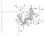
- FIG. 1is a side cross sectional view showing a first embodiment of a seal member according to the invention
- FIG. 2is a cross sectional view showing first embodiment in an eccentric state.
- a cylinder head cover 2 of an engineis provided with an ignition plug tube insertion opening or an opening 3 for insertion of an ignition plug tube therethrough.
- an annular stepped portion 4is formed around the opening 3 .
- the annular stepped portion 4is formed by providing a cylindrical wall or an annular wall 2 a located on a somewhat radially outward side with respect to the opening 3 and extending around the same.
- the annular wall 2 aprojects inwardly of the cylinder head cover 2 (i.e., downwardly in FIG. 1) and surrounds an ignition plug tube 8 .
- An inner peripheral surface of the annular wall 2 a and that portion of an inner surface (i.e., a lower surface in FIG. 1) of the cylinder head cover 2which is located on an diametrically inner side with respect to the annular wall 2 a , constitute the annular stepped portion 4 .
- the annular stepped portion 4has a peripheral surface 4 a corresponding to the inner peripheral surface of the annular wall 2 a and an upper surface 4 b corresponding to that portion of an inner surface of the cylinder head cover 2 , which is located on the diametrically inner side with respect to the annular wall 2 a.
- a seal member 1is fitted and mounted inside the annular stepped portion 4 , and then a baffle plate 5 is fused to a lower surface 2 a ′ of the cylinder head cover 2 , i.e., a lower surface of the annular wall 2 a . In this manner, the seal member 1 is mounted between the cylinder head cover 2 and the baffle plate 5 .
- the seal member 1comprises a mount portion 7 formed to be at least partially smaller in diameter than an inner diameter of the peripheral surface 4 a of the annular stepped portion 4 and interposed between the upper surface 4 b of the annular stepped portion 4 and the baffle plate 5 to be movable in a diametrical direction, a first annular seal portion 6 held by the mount portion 7 and projects radially outwards from the mount portion 7 to be brought into contact with the peripheral surface 4 a of the annular stepped portion 4 , and a second annular seal portion 9 projecting radially inwards from the mount portion 7 to be brought into contact with a peripheral surface 8 a of the ignition plug tube 8 .
- the first seal portion 6is formed to have a shape of a lip which obliquely extends radially outwards and downwards to contact at its tip end with the peripheral surface 4 a of the annular stepped portion 4 .
- the second seal portion 9is formed of a flexible material to be elastically deformable following relative radial movements between the mount portion 7 and the ignition plug tube 8 .
- the second seal portion 9is formed into a shape having an outer peripheral portion 9 a extending radially inwards from the mount portion 7 by a small distance and then bent axially downwards, and an inner peripheral portion 9 b obliquely extending radially inwards and upwards from a radially inner end of the outer peripheral portion 9 a.
- an annular spring 10acting to press the tip end of the second seal portion 9 against the peripheral surface 8 a of the ignition plug tube 8 .
- That portion of the mount portion 7which contacts with the upper surface 4 b of the annular stepped portion 4 , is provided with a plurality of bump-shaped projections 15 spaced from one another circumferentially of the mount portion 7 .
- the projections 15are embossed projections.
- the mount portion 7is provided at its lower end with a projection 12 , which projects in the same direction as the first seal portion 6 , that is, obliquely projects radially outwards and downwards to form a lip shape and continuously annularly extends circumferentially of the mount portion 7 .
- One or both of the projections 12 and 15may be omitted.
- the projections 12 and 15there is obtained an advantage that an interfacial friction of the mount portion 7 with the baffle plate 5 and the upper surface 4 b of the annular stepped portion 4 is reduced and hence radial movement of the mount portion 7 is facilitated.
- the projection 15is of course possible to constitute the projection 15 as an annular projection continuing circumferentially of the mount portion 7 or to constitute the projection 12 from a plurality of lip-shaped projections spaced apart from one another circumferentially of the mount portion 7 . That is, these projections may be continuous or discontinuous in the circumferential direction.
- the second seal portion 9 of the seal member 1is pushed in the eccentric direction, i.e., rightwardly. More specifically, that portion of the second seal portion 9 , which contacts with the ignition plug tube 8 , is pressed to be deformed, and the pressing force is transmitted to the mount portion 7 connected to the second seal portion 9 , so that the mount portion 7 is moved in the diametrical or rightward direction. At this time, the first seal portion 6 in the form of a lip is pushed toward the peripheral surface 4 a of the annular stepped portion 4 and deformed.
- a reinforcement ring 13is provided near the outer peripheral portion 9 a of the second seal portion 9 , as shown in FIG. 1 . That is, the ring 13 is provided at that portion of the second seal portion 9 , which is located radially outwardly with respect to a substantially central position between the ignition plug tube 8 and the mount portion 7 .
- a projection 11is provided to extend downwardly from the upper surface 4 b of the annular stepped portion 4 and to face the reinforcement ring 13 .
- the projection 11may be formed as an annular projection continuing circumferentially of the annular stepped portion 4 or as annular projections arranged to define a discrete or discontinuous annular configuration circumferentially of the annular stepped portion.
- the reinforcement ring 13 and the projection 11abut against each other to suppress deformation of more than a predetermined amount.
- the sealing performance of the second seal portion 9can be maintained.
- the mount portion 7When the mount portion 7 is moved radially according to an eccentricity caused on the ignition plug tube 8 , the mount portion 7 may slide as a whole or only a portion of the mount portion 7 located on the side of the baffle plate 5 may slide. In the case where the mount portion 7 slides as a whole, the first seal portion 6 in the form of a lip is deformed and the entire mount portion 7 is moved radially. Further, in the case where only a portion (lower portion in FIG. 1) of the mount portion 7 located on the side of the baffle plate 5 slides, the mount portion 7 flexes (distorts) radially, whereby only a lower portion of the mount portion 7 is moved radially. It is possible to cause both of the sliding movements described above, i.e., radial sliding of the entire mount portion 7 and radial sliding of the portion (lower portion in FIG. 1) of the mount portion 7 located on the side of the baffle plate 5 .
- the projection 11is formed as a continuous, annular projection, a closed space 16 a enclosed by the first seal portion 6 , the mount portion 7 , the peripheral surface 4 a of the annular stepped portion 4 , and the projection 11 is formed at the time of assembly when the seal member 1 is inserted into the groove 16 between the peripheral surface 4 a of the annular stepped portion 4 and the projection 11 . Accordingly, insertion of the seal member 1 into the groove 16 becomes difficult or insufficient.
- a first seal portion 6 Ais constructed as a projection in the form of a rectangular ring projecting radially outward from the mount portion 7 and contacting with the peripheral surface 4 a of the annular stepped portion 4 .
- the projectionmay be in the form of an O-ring or the like.
- the lip-shaped projection 12 in the first embodimentis omitted and a projection 15 A is provided instead of the bump-shaped projections 15 .
- the projection 15 Ais a lip-shaped projection inclined in a radially inward and upward direction.
- the projection 15 Acooperates with the first seal portion 6 , which extends outwardly downwards, to improve sealing performance, coping with both of the cases where pressure in the cylinder head cover 2 becomes positive and negative relative to the atmospheric pressure.
- the projection 15 Amay be an annular projection continuing circumferentially of the mount portion 7 or a plurality of lip-shaped projections spaced from one another circumferentially of the mount portion 7 . That is, the projection 15 A may be an annular projections continuing circumferentially or annular projections discontinuing circumferentially.
Landscapes
- Engineering & Computer Science (AREA)
- General Engineering & Computer Science (AREA)
- Mechanical Engineering (AREA)
- Chemical & Material Sciences (AREA)
- Combustion & Propulsion (AREA)
- Ignition Installations For Internal Combustion Engines (AREA)
- Gasket Seals (AREA)
Abstract
Description
Claims (9)
Applications Claiming Priority (4)
| Application Number | Priority Date | Filing Date | Title |
|---|---|---|---|
| JP2001-066059 | 2001-03-09 | ||
| JP2001066059 | 2001-03-09 | ||
| JP2002-057539 | 2002-03-04 | ||
| JP2002057539AJP4014423B2 (en) | 2001-03-09 | 2002-03-04 | Sealing device for spark plug tube insertion portion in cylinder head cover |
Publications (2)
| Publication Number | Publication Date |
|---|---|
| US20020130472A1 US20020130472A1 (en) | 2002-09-19 |
| US6702293B2true US6702293B2 (en) | 2004-03-09 |
Family
ID=26610917
Family Applications (1)
| Application Number | Title | Priority Date | Filing Date |
|---|---|---|---|
| US10/092,731Expired - LifetimeUS6702293B2 (en) | 2001-03-09 | 2002-03-08 | Seal member mounted between cylinder head cover and ignition plug tube |
Country Status (2)
| Country | Link |
|---|---|
| US (1) | US6702293B2 (en) |
| JP (1) | JP4014423B2 (en) |
Cited By (23)
| Publication number | Priority date | Publication date | Assignee | Title |
|---|---|---|---|---|
| US20040201181A1 (en)* | 2003-04-09 | 2004-10-14 | Williamson Alexander S. | Flange seal |
| US20060186603A1 (en)* | 2005-02-24 | 2006-08-24 | Freudenberg-Nok General Partnership | Dynamic seal |
| US20080029052A1 (en)* | 2006-06-07 | 2008-02-07 | Honda Motor Co., Ltd. | Mounting structure of ignition plug tube |
| US20080217865A1 (en)* | 2007-03-09 | 2008-09-11 | Brent Ryan Sedlar | Dynamic shaft seal and method of installation thereof |
| US20080251347A1 (en)* | 2007-04-12 | 2008-10-16 | Nok Corporation | Piston for hydraulic clutch |
| US20090032366A1 (en)* | 2007-08-03 | 2009-02-05 | Nok Corporation | Piston for automatic transmission |
| US20090145393A1 (en)* | 2007-12-06 | 2009-06-11 | Freudenberg-Nok General Partnership | Valve Stem Seal With Gas Relief Features |
| US20090146382A1 (en)* | 2007-12-06 | 2009-06-11 | Freudenberg-Nok General Partnership | Valve Stem Seal With Gas Relief Features |
| US7770897B2 (en) | 2005-02-24 | 2010-08-10 | Freudenberg-Nok General Partnership | Dynamic seal |
| US7775528B2 (en) | 2006-02-13 | 2010-08-17 | Freudenberg-Nok General Partnership | Bi-directional pattern for dynamic seals |
| US20100219588A1 (en)* | 2006-02-10 | 2010-09-02 | Freudenberg-Nok General Partnership | Seal with Spiral Grooves and Contamination Entrapment Dams |
| US20110204579A1 (en)* | 2010-02-24 | 2011-08-25 | Freudenberg-Nok General Partnership | Seal with Spiral Grooves and Mid-Lip Band |
| US20130307228A1 (en)* | 2012-05-18 | 2013-11-21 | Freudenberg-Nok General Partnership | Low Load Seal With Outer Diameter Flap |
| US8590903B2 (en)* | 2009-03-24 | 2013-11-26 | Freudenberg-Nok General Partnership | Lip seal with inversion prevention feature |
| US20140020647A1 (en)* | 2011-04-06 | 2014-01-23 | Mahle Filter Systems Japan Corporation | Seal member, and plug tube seal structure for engine |
| US8919782B2 (en) | 2012-10-19 | 2014-12-30 | Freudenberg-Nok General Partnership | Dynamic lay down lip seal with bidirectional pumping feature |
| US8925927B2 (en) | 2006-02-10 | 2015-01-06 | Freudenberg-Nok General Partnership | Seal with controllable pump rate |
| US9695937B2 (en) | 2014-02-04 | 2017-07-04 | Freudenberg-Nok General Partnership | Energy saving seal with vacuum induced counter-balance and rocking feature |
| US9714710B2 (en) | 2014-02-04 | 2017-07-25 | Freudenberg-Nok General Partnership | Energy saving self-contact seal with pushing bead |
| US9759330B2 (en) | 2014-02-04 | 2017-09-12 | Freudenberg-Nok General Partnership | Energy saving seal with rocking dust lip |
| US11333248B2 (en)* | 2017-04-19 | 2022-05-17 | Nok Corporation | Positive/negative pressure gasket |
| US11549466B2 (en) | 2019-02-18 | 2023-01-10 | Caterpillar Energy Solutions Gmbh | Seal and method for a fuel gas supply to a pre-combustion chamber |
| US11639754B2 (en) | 2019-10-03 | 2023-05-02 | Nok Corporation | Positive/negative pressure gasket |
Families Citing this family (5)
| Publication number | Priority date | Publication date | Assignee | Title |
|---|---|---|---|---|
| JPWO2006077677A1 (en)* | 2005-01-21 | 2008-06-19 | Nok株式会社 | gasket |
| JP2006300312A (en)* | 2005-03-24 | 2006-11-02 | Nok Corp | Sealing device |
| FR2889279B1 (en)* | 2005-07-29 | 2007-11-02 | Freudenberg Meillor Soc Par Ac | SEAL FOR CANDLE WELL |
| JP5311649B2 (en)* | 2009-03-30 | 2013-10-09 | 内山工業株式会社 | Annular sealing device |
| JP7441849B2 (en)* | 2019-09-30 | 2024-03-01 | Nok株式会社 | sealing device |
Citations (12)
| Publication number | Priority date | Publication date | Assignee | Title |
|---|---|---|---|---|
| US4448461A (en)* | 1982-03-16 | 1984-05-15 | The Timken Company | Self-venting seal |
| US4484751A (en)* | 1983-02-19 | 1984-11-27 | Goetze Ag | Crankcase housing cover with sealing means |
| JPS62195643A (en) | 1986-02-21 | 1987-08-28 | Konishiroku Photo Ind Co Ltd | Silver halide photographic sensitive material having improved sensitivity, picture quality and pressure fogging |
| US5167419A (en)* | 1991-10-22 | 1992-12-01 | Freudenberg-Nok General Partnership | Fluid seal with integral check valve |
| US5228420A (en)* | 1992-09-25 | 1993-07-20 | Tsuchiya Mfg. Co., Ltd. | Valve rocker cover |
| US5299677A (en)* | 1991-10-15 | 1994-04-05 | Claude Caillaud | Guide-tube with integral sealing for motor vehicle gearbox clutch release bearing |
| US5329898A (en)* | 1993-05-05 | 1994-07-19 | Freudenerg-Nok General Partnership | Shaft seal and bore assembly |
| US5462288A (en)* | 1993-03-12 | 1995-10-31 | Dichtungstechnik G. Bruss Gmbh & Co. Kg | Shaft seal assembly |
| US5462889A (en)* | 1991-11-08 | 1995-10-31 | Nec Corporation | Method of fabricating a semiconductor device with a polycrystalline silicon resistive layer |
| JPH09133068A (en)* | 1995-11-13 | 1997-05-20 | Denso Corp | Ignition device for internal combustion engine |
| US5771870A (en)* | 1995-12-06 | 1998-06-30 | Denso Corporation | Ignition coil for an internal combustion engine |
| US6227186B1 (en)* | 1998-11-27 | 2001-05-08 | Robert Bosch Gmbh | Ignition system for an internal combustion engine |
- 2002
- 2002-03-04JPJP2002057539Apatent/JP4014423B2/ennot_activeExpired - Fee Related
- 2002-03-08USUS10/092,731patent/US6702293B2/ennot_activeExpired - Lifetime
Patent Citations (12)
| Publication number | Priority date | Publication date | Assignee | Title |
|---|---|---|---|---|
| US4448461A (en)* | 1982-03-16 | 1984-05-15 | The Timken Company | Self-venting seal |
| US4484751A (en)* | 1983-02-19 | 1984-11-27 | Goetze Ag | Crankcase housing cover with sealing means |
| JPS62195643A (en) | 1986-02-21 | 1987-08-28 | Konishiroku Photo Ind Co Ltd | Silver halide photographic sensitive material having improved sensitivity, picture quality and pressure fogging |
| US5299677A (en)* | 1991-10-15 | 1994-04-05 | Claude Caillaud | Guide-tube with integral sealing for motor vehicle gearbox clutch release bearing |
| US5167419A (en)* | 1991-10-22 | 1992-12-01 | Freudenberg-Nok General Partnership | Fluid seal with integral check valve |
| US5462889A (en)* | 1991-11-08 | 1995-10-31 | Nec Corporation | Method of fabricating a semiconductor device with a polycrystalline silicon resistive layer |
| US5228420A (en)* | 1992-09-25 | 1993-07-20 | Tsuchiya Mfg. Co., Ltd. | Valve rocker cover |
| US5462288A (en)* | 1993-03-12 | 1995-10-31 | Dichtungstechnik G. Bruss Gmbh & Co. Kg | Shaft seal assembly |
| US5329898A (en)* | 1993-05-05 | 1994-07-19 | Freudenerg-Nok General Partnership | Shaft seal and bore assembly |
| JPH09133068A (en)* | 1995-11-13 | 1997-05-20 | Denso Corp | Ignition device for internal combustion engine |
| US5771870A (en)* | 1995-12-06 | 1998-06-30 | Denso Corporation | Ignition coil for an internal combustion engine |
| US6227186B1 (en)* | 1998-11-27 | 2001-05-08 | Robert Bosch Gmbh | Ignition system for an internal combustion engine |
Cited By (38)
| Publication number | Priority date | Publication date | Assignee | Title |
|---|---|---|---|---|
| US20040201181A1 (en)* | 2003-04-09 | 2004-10-14 | Williamson Alexander S. | Flange seal |
| US8066287B2 (en) | 2005-02-24 | 2011-11-29 | Freudenberg-Nok General Partnership | Dynamic seal |
| US7770897B2 (en) | 2005-02-24 | 2010-08-10 | Freudenberg-Nok General Partnership | Dynamic seal |
| US7854433B2 (en) | 2005-02-24 | 2010-12-21 | Freudenberg-Nok General Partnership | Dynamic seal |
| US8011673B2 (en) | 2005-02-24 | 2011-09-06 | Freudenberg-Nok General Partnership | Dynamic seal |
| US7854432B2 (en) | 2005-02-24 | 2010-12-21 | Freudenberg-Nok General Partnership | Dynamic seal |
| US20060186603A1 (en)* | 2005-02-24 | 2006-08-24 | Freudenberg-Nok General Partnership | Dynamic seal |
| US8925927B2 (en) | 2006-02-10 | 2015-01-06 | Freudenberg-Nok General Partnership | Seal with controllable pump rate |
| US8376369B2 (en) | 2006-02-10 | 2013-02-19 | Freudenberg-Nok General Partnership | Seal with spiral grooves and contamination entrapment dams |
| US20100219588A1 (en)* | 2006-02-10 | 2010-09-02 | Freudenberg-Nok General Partnership | Seal with Spiral Grooves and Contamination Entrapment Dams |
| US7775528B2 (en) | 2006-02-13 | 2010-08-17 | Freudenberg-Nok General Partnership | Bi-directional pattern for dynamic seals |
| US20080029052A1 (en)* | 2006-06-07 | 2008-02-07 | Honda Motor Co., Ltd. | Mounting structure of ignition plug tube |
| US7584733B2 (en)* | 2006-06-07 | 2009-09-08 | Honda Motor Co., Ltd. | Mounting structure of ignition plug tube |
| US8052152B2 (en) | 2007-03-09 | 2011-11-08 | Federal-Mogul Corporation | Dynamic shaft seal and method of installation thereof |
| US20080217865A1 (en)* | 2007-03-09 | 2008-09-11 | Brent Ryan Sedlar | Dynamic shaft seal and method of installation thereof |
| US7647864B2 (en)* | 2007-04-12 | 2010-01-19 | Nok Corporation | Piston for hydraulic clutch |
| US20080251347A1 (en)* | 2007-04-12 | 2008-10-16 | Nok Corporation | Piston for hydraulic clutch |
| US20090032366A1 (en)* | 2007-08-03 | 2009-02-05 | Nok Corporation | Piston for automatic transmission |
| US8668203B2 (en) | 2007-12-06 | 2014-03-11 | Freudenberg-Nok General Partnership | Valve stem seal with gas relief features |
| US9988950B2 (en) | 2007-12-06 | 2018-06-05 | Freudenberg-Nok General Partnership | Valve stem seal with gas relief features |
| US8235394B2 (en) | 2007-12-06 | 2012-08-07 | Freudenberg-Nok General Partnership | Valve stem seal with gas relief features |
| US20090146382A1 (en)* | 2007-12-06 | 2009-06-11 | Freudenberg-Nok General Partnership | Valve Stem Seal With Gas Relief Features |
| US20090145393A1 (en)* | 2007-12-06 | 2009-06-11 | Freudenberg-Nok General Partnership | Valve Stem Seal With Gas Relief Features |
| US8011669B2 (en)* | 2007-12-06 | 2011-09-06 | Freudenberg-Nok General Partnership | Valve stem seal with gas relief features |
| US8590903B2 (en)* | 2009-03-24 | 2013-11-26 | Freudenberg-Nok General Partnership | Lip seal with inversion prevention feature |
| US8454025B2 (en) | 2010-02-24 | 2013-06-04 | Freudenberg-Nok General Partnership | Seal with spiral grooves and mid-lip band |
| US20110204579A1 (en)* | 2010-02-24 | 2011-08-25 | Freudenberg-Nok General Partnership | Seal with Spiral Grooves and Mid-Lip Band |
| US20140020647A1 (en)* | 2011-04-06 | 2014-01-23 | Mahle Filter Systems Japan Corporation | Seal member, and plug tube seal structure for engine |
| US9169803B2 (en)* | 2011-04-06 | 2015-10-27 | Honda Motor Co., Ltd. | Seal member, and plug tube seal structure for engine |
| US20130307228A1 (en)* | 2012-05-18 | 2013-11-21 | Freudenberg-Nok General Partnership | Low Load Seal With Outer Diameter Flap |
| US10514101B2 (en) | 2012-05-18 | 2019-12-24 | Freudenberg—NOK General Partnership | Low load seal with outer diameter flap |
| US8919782B2 (en) | 2012-10-19 | 2014-12-30 | Freudenberg-Nok General Partnership | Dynamic lay down lip seal with bidirectional pumping feature |
| US9759330B2 (en) | 2014-02-04 | 2017-09-12 | Freudenberg-Nok General Partnership | Energy saving seal with rocking dust lip |
| US9714710B2 (en) | 2014-02-04 | 2017-07-25 | Freudenberg-Nok General Partnership | Energy saving self-contact seal with pushing bead |
| US9695937B2 (en) | 2014-02-04 | 2017-07-04 | Freudenberg-Nok General Partnership | Energy saving seal with vacuum induced counter-balance and rocking feature |
| US11333248B2 (en)* | 2017-04-19 | 2022-05-17 | Nok Corporation | Positive/negative pressure gasket |
| US11549466B2 (en) | 2019-02-18 | 2023-01-10 | Caterpillar Energy Solutions Gmbh | Seal and method for a fuel gas supply to a pre-combustion chamber |
| US11639754B2 (en) | 2019-10-03 | 2023-05-02 | Nok Corporation | Positive/negative pressure gasket |
Also Published As
| Publication number | Publication date |
|---|---|
| JP2002332914A (en) | 2002-11-22 |
| JP4014423B2 (en) | 2007-11-28 |
| US20020130472A1 (en) | 2002-09-19 |
Similar Documents
| Publication | Publication Date | Title |
|---|---|---|
| US6702293B2 (en) | Seal member mounted between cylinder head cover and ignition plug tube | |
| JP4639619B2 (en) | Sealing device for reciprocating shaft | |
| US6565096B2 (en) | Lip type seal | |
| US6422570B2 (en) | Lip type seal | |
| CN1229460A (en) | Bellows Elastomeric Seals | |
| US7648144B2 (en) | Sealing device | |
| JP5504132B2 (en) | Snap-in valve and tire valve unit | |
| EP3339695B1 (en) | Valve stem seal and hermetic sealing structure | |
| US11149784B2 (en) | Dust cover | |
| JP5216786B2 (en) | Fluid dispenser pump and dispenser having the pump | |
| JPS6143003Y2 (en) | ||
| CN101975298B (en) | Gas bleeder plug, bearing device and bearing | |
| CN113874640B (en) | Sealing device | |
| CN101124422B (en) | gas release plug, bearing device and bearing | |
| GB2028966A (en) | Gas spring with end stop | |
| US20220333689A1 (en) | Gasket | |
| JP2579758Y2 (en) | gasket | |
| JP7489816B2 (en) | Sealing device and sealing structure | |
| CN113994127B (en) | Sealing device | |
| JP3982804B2 (en) | Seal structure | |
| JP3760327B2 (en) | Sealing device | |
| JPH0835563A (en) | Sealing device for reciprocating movement | |
| JP4165315B2 (en) | Seal structure of constant velocity joint boot | |
| JP3212050B2 (en) | Liquid filled type vibration damping device | |
| JPH045715Y2 (en) |
Legal Events
| Date | Code | Title | Description |
|---|---|---|---|
| AS | Assignment | Owner name:MAHLE TENNEX CORPORATION, JAPAN Free format text:ASSIGNMENT OF ASSIGNORS INTEREST;ASSIGNORS:ENDO, KAZUTOYO;MATSUI, NORIMASA;REEL/FRAME:013026/0339 Effective date:20020522 Owner name:KEEPER CO., LTD., JAPAN Free format text:ASSIGNMENT OF ASSIGNORS INTEREST;ASSIGNORS:ENDO, KAZUTOYO;MATSUI, NORIMASA;REEL/FRAME:013026/0339 Effective date:20020522 | |
| STCF | Information on status: patent grant | Free format text:PATENTED CASE | |
| AS | Assignment | Owner name:MAHLE FILTER SYSTEMS JAPAN CORPORATION, JAPAN Free format text:CHANGE OF NAME;ASSIGNOR:MAHLE TENNEX CORPORATION, FORMERLY KNOWN AS TENNEX CORPORATION;REEL/FRAME:017759/0354 Effective date:20051201 Owner name:MAHLE FILTER SYSTEMS JAPAN CORPORATION, JAPAN Free format text:CHANGE OF NAME;ASSIGNOR:MAHLE TENNEX CORPORATION, FORMERLY KNOWN AS TENNEX CORPORATION;REEL/FRAME:017759/0321 Effective date:20051201 | |
| FPAY | Fee payment | Year of fee payment:4 | |
| FPAY | Fee payment | Year of fee payment:8 | |
| FPAY | Fee payment | Year of fee payment:12 |