US6701392B1 - Hierarchical approach to indentifying changing device characteristics - Google Patents
Hierarchical approach to indentifying changing device characteristicsDownload PDFInfo
- Publication number
- US6701392B1 US6701392B1US09/998,494US99849401AUS6701392B1US 6701392 B1US6701392 B1US 6701392B1US 99849401 AUS99849401 AUS 99849401AUS 6701392 B1US6701392 B1US 6701392B1
- Authority
- US
- United States
- Prior art keywords
- stored
- data
- memory
- status information
- configuration
- Prior art date
- Legal status (The legal status is an assumption and is not a legal conclusion. Google has not performed a legal analysis and makes no representation as to the accuracy of the status listed.)
- Expired - Lifetime, expires
Links
Images


Classifications
- G—PHYSICS
- G06—COMPUTING OR CALCULATING; COUNTING
- G06F—ELECTRIC DIGITAL DATA PROCESSING
- G06F11/00—Error detection; Error correction; Monitoring
- G06F11/07—Responding to the occurrence of a fault, e.g. fault tolerance
- G06F11/16—Error detection or correction of the data by redundancy in hardware
- G06F11/1666—Error detection or correction of the data by redundancy in hardware where the redundant component is memory or memory area
- G—PHYSICS
- G06—COMPUTING OR CALCULATING; COUNTING
- G06F—ELECTRIC DIGITAL DATA PROCESSING
- G06F11/00—Error detection; Error correction; Monitoring
- G06F11/07—Responding to the occurrence of a fault, e.g. fault tolerance
- G06F11/16—Error detection or correction of the data by redundancy in hardware
- G06F11/20—Error detection or correction of the data by redundancy in hardware using active fault-masking, e.g. by switching out faulty elements or by switching in spare elements
- G06F11/2053—Error detection or correction of the data by redundancy in hardware using active fault-masking, e.g. by switching out faulty elements or by switching in spare elements where persistent mass storage functionality or persistent mass storage control functionality is redundant
- G06F11/2056—Error detection or correction of the data by redundancy in hardware using active fault-masking, e.g. by switching out faulty elements or by switching in spare elements where persistent mass storage functionality or persistent mass storage control functionality is redundant by mirroring
- G06F11/2069—Management of state, configuration or failover
- G—PHYSICS
- G06—COMPUTING OR CALCULATING; COUNTING
- G06F—ELECTRIC DIGITAL DATA PROCESSING
- G06F3/00—Input arrangements for transferring data to be processed into a form capable of being handled by the computer; Output arrangements for transferring data from processing unit to output unit, e.g. interface arrangements
- G06F3/06—Digital input from, or digital output to, record carriers, e.g. RAID, emulated record carriers or networked record carriers
- G06F3/0601—Interfaces specially adapted for storage systems
- G06F3/0602—Interfaces specially adapted for storage systems specifically adapted to achieve a particular effect
- G06F3/0604—Improving or facilitating administration, e.g. storage management
- G—PHYSICS
- G06—COMPUTING OR CALCULATING; COUNTING
- G06F—ELECTRIC DIGITAL DATA PROCESSING
- G06F3/00—Input arrangements for transferring data to be processed into a form capable of being handled by the computer; Output arrangements for transferring data from processing unit to output unit, e.g. interface arrangements
- G06F3/06—Digital input from, or digital output to, record carriers, e.g. RAID, emulated record carriers or networked record carriers
- G06F3/0601—Interfaces specially adapted for storage systems
- G06F3/0628—Interfaces specially adapted for storage systems making use of a particular technique
- G06F3/0629—Configuration or reconfiguration of storage systems
- G06F3/0631—Configuration or reconfiguration of storage systems by allocating resources to storage systems
- G—PHYSICS
- G06—COMPUTING OR CALCULATING; COUNTING
- G06F—ELECTRIC DIGITAL DATA PROCESSING
- G06F3/00—Input arrangements for transferring data to be processed into a form capable of being handled by the computer; Output arrangements for transferring data from processing unit to output unit, e.g. interface arrangements
- G06F3/06—Digital input from, or digital output to, record carriers, e.g. RAID, emulated record carriers or networked record carriers
- G06F3/0601—Interfaces specially adapted for storage systems
- G06F3/0628—Interfaces specially adapted for storage systems making use of a particular technique
- G06F3/0655—Vertical data movement, i.e. input-output transfer; data movement between one or more hosts and one or more storage devices
- G06F3/0659—Command handling arrangements, e.g. command buffers, queues, command scheduling
- G—PHYSICS
- G06—COMPUTING OR CALCULATING; COUNTING
- G06F—ELECTRIC DIGITAL DATA PROCESSING
- G06F3/00—Input arrangements for transferring data to be processed into a form capable of being handled by the computer; Output arrangements for transferring data from processing unit to output unit, e.g. interface arrangements
- G06F3/06—Digital input from, or digital output to, record carriers, e.g. RAID, emulated record carriers or networked record carriers
- G06F3/0601—Interfaces specially adapted for storage systems
- G06F3/0668—Interfaces specially adapted for storage systems adopting a particular infrastructure
- G06F3/0671—In-line storage system
- G06F3/0683—Plurality of storage devices
- G06F3/0689—Disk arrays, e.g. RAID, JBOD
- G—PHYSICS
- G06—COMPUTING OR CALCULATING; COUNTING
- G06F—ELECTRIC DIGITAL DATA PROCESSING
- G06F11/00—Error detection; Error correction; Monitoring
- G06F11/07—Responding to the occurrence of a fault, e.g. fault tolerance
- G06F11/16—Error detection or correction of the data by redundancy in hardware
- G06F11/20—Error detection or correction of the data by redundancy in hardware using active fault-masking, e.g. by switching out faulty elements or by switching in spare elements
Definitions
- This applicationrelates to computer storage devices, and more particularly to communication between storage devices.
- Host processor systemsmay store and retrieve data using a storage device containing a plurality of host interface units (host adapters), disk drives, and disk interface units (disk adapters).
- host adaptershost interface units
- disk drivesdisk interface units
- disk adaptersdisk adapters
- Such storage devicesare provided, for example, by EMC Corporation of Hopkinton, Mass. and disclosed in U.S. Pat. No. 5,206,939 to Yanai et al., U.S. Pat. No. 5,778,394 to Galtzur et al., U.S. Pat. No. 5,845,147 to Vishlitzky et al., and U.S. Pat. No. 5,857,208 to Ofek.
- the host systemsaccess the storage device through a plurality of channels provided therewith.
- Host systemsprovide data and access control information through the channels to the storage device and the storage device provides data to the host systems also through the channels.
- the host systemsdo not address the disk drives of the storage device directly, but rather, access what appears to the host systems as a plurality of logical disk units.
- the logical disk unitsmay or may not correspond to the actual disk drives. Allowing multiple host systems to access the single storage device unit allows the host systems to share data stored therein. correspond to the actual disk drives. Allowing multiple host systems to access the single storage device unit allows the host systems to share data stored therein.
- RDFRemote Data Facility
- a usermay denote a first storage device as a master storage device and a second storage device as a slave storage device.
- Other incarnations of RDFmay provide a peer to peer relationship between the local and remote storage devices.
- the hostinteracts directly with the local storage device, but any data changes made to the local storage device are automatically provided to a remote storage device using RDF.
- the local and remote storage devicesmay be connected by a data link, such as an ESCON link or a Fiber Channel link.
- the RDF functionalitymay be facilitated with an RDF adapter (RA) provided at each of the storage devices.
- RARDF adapter
- RDF configuration systemit may be desirable to modify the RDF configuration system. However, in many cases, such modifications require skilled technicians using special software and non-standard connections to the local storage devices. It is desirable to automate the RDF configuration modification process to allow a host to modify the RDF configuration. In addition, it is desirable that allowing dynamic modifications to RDF configuration will not effect operation of the storage device when individual devices therein need to access the dynamic configuration information.
- determining device characteristicsincludes obtaining a first globally accessible value, if the first globally accessible value corresponds to a stored first value, obtaining device characteristics data from a relatively fast memory, if the first globally accessible value does not correspond to the stored first value, obtaining a second globally accessible value, if the second globally accessible value corresponds to a stored second value, obtaining device characteristics data from a relatively fast memory, if the second globally accessible value does not correspond to the stored second value, obtaining device characteristics data from a relatively slow memory and updating the relatively fast memory, the stored first value, and the stored second value.
- the globally accessible first valuemay include device I/O information.
- the globally accessible valuesmay be stored in global memory that is accessible to a plurality of processors.
- the relatively slow memorymay be global memory that is accessible to a plurality of processors.
- the relatively fast memorymay be local to a processor that accesses the first and second stored values.
- the second stored valuemay indicate whether a device is a source or a destination for data in a remote data communication link.
- accessing a deviceincludes obtaining status information that indicates how to access the device, examining at least a portion of the status information to determine if configuration of the device has changed, if the configuration of the device has not changed, accessing stored configuration data from relatively fast memory, and if the configuration of the device has changed, accessing new configuration information from relatively slow memory and updating the stored configuration data with the new configuration information.
- the relatively slow memorymay be global memory that is accessible to a plurality of processors.
- the relatively fast memorymay be local to a processor that accesses the fast memory.
- the stored configuration datamay indicate whether a device is a source or a destination for data in a remote data communication link.
- Examining at least a portion of the status informationmay include determining whether the portion of the status information is equal to a first stored value. Accessing a device may also include, if the portion of the status information is not equal to the first stored value, obtaining additional status information and determining if a portion of the additional status information is equal to a second stored value. Accessing a device may also include following updating the stored configuration data, updating the first and second stored values.
- a computer program product that determines device characteristicsincludes executable code that obtains a first globally accessible value, executable code that obtains device characteristics data from a relatively fast memory if the first globally accessible value corresponds to a stored first value, executable code that obtains a second globally accessible value if the first globally accessible value does not correspond to the stored first value, executable code that obtains device characteristics data from a relatively fast memory if the second globally accessible value corresponds to a stored second value, and executable code that obtains device characteristics data from a relatively slow memory and updates the relatively fast memory, the stored first value, and the stored second value if the second globally accessible value does not correspond to the stored second value.
- the globally accessible first valuemay include device I/O information.
- the second stored valuemay indicate whether a device is a source or a destination for data in a remote data communication link.
- a computer program product that accesses a deviceincludes executable code that obtains status information that indicates how to access the device, executable code that examines at least a portion of the status information to determine if configuration of the device has changed, executable code that accesses stored configuration data from relatively fast memory if the configuration of the device has not changed, and executable code that accesses new configuration information from relatively slow memory and updates the stored configuration data with the new configuration information if the configuration of the device has changed.
- the stored configuration datamay indicate whether a device is a source or a destination for data in a remote data communication link.
- Executable code that examines at least a portion of the status informationmay include executable code that determines whether the portion of the status information is equal to a first stored value.
- a computer program product that accesses a devicemay also include executable code that obtains additional status information and determines if a portion of the additional status information is equal to a second stored value if the portion of the status information is not equal to the first stored value.
- a computer program product that accesses a devicemay also include executable code that updates the first and second stored values following updating the stored configuration data.
- an apparatus that determines device characteristicsincludes means for obtaining a first globally accessible value, means for obtaining device characteristics data from a relatively fast memory if the first globally accessible value corresponds to a stored first value, means for obtaining a second globally accessible value if the first globally accessible value does not correspond to the stored first value, means for obtaining device characteristics data from a relatively fast memory if the second globally accessible value corresponds to a stored second value, means for obtaining device characteristics data from a relatively slow memory and updating the relatively fast memory, the stored first value, and the stored second value if the second globally accessible value does not correspond to the stored second value.
- the globally accessible first valuemay include device I/O information.
- the globally accessible valuesmay be stored in global memory that is accessible to a plurality of processors.
- the relatively slow memorymay be global memory that is accessible to a plurality of processors.
- the relatively fast memorymay be local to a processor that accesses the first and second stored values.
- the second stored valuemay indicate whether a device is a source or a destination for data in a remote data communication link.
- an apparatus that accesses a deviceincludes means for obtaining status information that indicates how to access the device, means for examining at least a portion of the status information to determine if configuration of the device has changed, means for accessing stored configuration data from relatively fast memory if the configuration of the device has not changed, and means for accessing new configuration information from relatively slow memory and updating the stored configuration data with the new configuration information if the configuration of the device has changed.
- the relatively slow memorymay be global memory that is accessible to a plurality of processors.
- the relatively fast memorymay be local to a processor that accesses the fast memory.
- the stored configuration datamay indicate whether a device is a source or a destination for data in a remote data communication link.
- Means for examining at least a portion of the status informationmay include means for determining whether the portion of the status information is equal to a first stored value.
- the apparatusmay further include means for obtaining additional status information and determining if a portion of the additional status information is equal to a second stored value if the portion of the status information is not equal to the first stored value.
- the apparatusmay further include means for updating the first and second stored values following updating the stored configuration data.
- FIG. 1is a schematic diagram showing a host, a local storage device, and a remote data storage device used in connection with the system described herein.
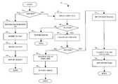
- FIG. 2is a flow chart illustrating operation of the system described herein.
- FIG. 3is a flow chart illustrating determining which volumes to use for read and write operations according to the system described herein.
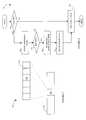
- FIG. 4is a diagram illustrating global memory for storage devices according to the system described herein.
- FIG. 5is a flow chart illustrating a hierarchy for determining whether to use static or dynamic configuration data in connection with assessing RDF configuration of a device according to the system described herein.
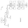
- FIG. 6is a schematic diagram showing in detail a storage device and components thereof used in connection with the system described herein.
- FIG. 7is a diagram illustrating a ready buffer and a set of bytes used in connection with the system described herein.
- FIG. 8is a flow chart illustrating steps performed in connection with accessing the ready buffer and the set of bytes set forth in FIG. 7 .
- FIG. 9is a flow chart illustrating an alternative embodiment of the system described herein.
- a diagram 20shows a relationship between a host 22 , a local storage device 24 and a remote storage device 26 .
- the host 22reads and writes data from and to the local storage device 24 via a host adapter 28 , which facilitates the interface between the host 22 and the local storage device 24 .
- Data from the local storage device 24is copied to the remote storage device 26 via an RDF link 29 to cause the data on the remote storage device 26 to be identical to the data on the local storage device 24 .
- Communication using RDFis described, for example, in U.S. Pat. Nos. 5,742,792, and 5,544,346, both of which are incorporated by reference herein.
- the local storage device 24includes an RDF adapter unit (RA) 30 and the remote storage device 26 includes an RA 32 .
- the RA's 30 , 32are coupled to the RDF link 29 and are similar to the host adapter 28 , but are used to transfer data between the storage devices 24 , 26 .
- the software used in connection with the RA's 30 , 32is discussed in more detail hereinafter.
- the storage devices 24 , 26may include one or more disks, each containing a different portion of data stored on each of the storage devices 24 , 26 .
- FIG. 1shows the storage device 24 including a plurality of disks 33 a , 33 b , 33 c and the storage device 26 including a plurality of disks 34 a , 34 b , 34 c .
- the RDF functionality described hereinmay be applied so that the data for at least a portion of the disks 33 a - 33 c of the local storage device 24 is copied, using RDF, to at least a portion of the disks 34 a - 34 c of the remote storage device 26 . It is possible that other data of the storage devices 24 , 26 is not copied between the storage devices 24 , 26 , and thus is not identical.
- Each of the disks 33 a - 33 cis coupled to a corresponding disk adapter unit (DA) 35 a , 35 b , 35 c that provides data to a corresponding one of the disks 33 a - 33 c and receives data from a corresponding one of the disks 33 a - 33 c .
- DAdisk adapter unit
- a plurality of DA's 36 a , 36 b , 36 c of the remote storage device 26are used to provide data to corresponding ones of the disks 34 a - 34 c and receive data from corresponding ones of the disks 34 a - 34 c .
- a data pathexists between the DA's 35 a - 35 c , the HA 28 and RA 30 of the local storage device 24 .
- a data pathexists between the DA's 36 a - 36 c and the RA 32 of the remote storage device 26 .
- the local storage device 24also includes a global memory 37 that may be used to facilitate data transferred between the DA's 35 a - 35 c , the HA 28 and the RA 30 .
- the memory 37may contain parameters from system calls, tasks that are to be performed by one or more of the DA's 35 a - 35 c , the HA 28 and the RA 30 , and a cache for data fetched from one or more of the disks 33 a - 33 c .
- the remote storage device 26includes a global memory 38 that may contain parameters from system calls, tasks that are to be performed by one or more of the DA's 36 a - 36 c and the RA 32 , and a cache for data fetched from one or more of the disks 34 a - 34 c .
- a global memory 38may contain parameters from system calls, tasks that are to be performed by one or more of the DA's 36 a - 36 c and the RA 32 , and a cache for data fetched from one or more of the disks 34 a - 34 c .
- the storage space in the local storage device 24 that corresponds to the disks 33 a - 33 cmay be subdivided into a plurality of volumes or logical devices.
- the logical devicesmay or may not correspond to the physical storage space of the disks 33 a - 33 c .
- the disk 33 amay contain a plurality of logical devices or, alternatively, a single logical device could span both of the disks 33 a , 33 b .
- the storage space for the remote storage device 26 that comprises the disks 34 a - 34 cmay be subdivided into a plurality of volumes or logical devices, where each of the logical devices may or may not correspond to one or more of the disks 34 a - 34 c.
- Providing an RDF mapping between portions of the local storage device 24 and the remote storage device 26involves setting up a logical device on the remote storage device 26 that is a remote mirror for a logical device on the local storage device 24 .
- the host 22reads and writes data from and to the logical device on the local storage device 24 and the RDF mapping causes modified data to be transferred from the local storage device 24 to the remote storage device 26 using the RAs, 30 , 32 and the RDF link 29 .
- the logical device on the remote storage device 26contains data that is identical to the data of the logical device on the local storage device 24 .
- the logical device on the local storage device 24 that is accessed by the host 22is referred to as the “R 1 volume” (or just “R 1 ”) while the logical device on the remote storage device 26 that contains a copy of the data on the R 1 volume is called the “R 2 volume” (or just “R 2 ”).
- R 1 volumeThe logical device on the local storage device 24 that is accessed by the host 22
- R 2 volumethe logical device on the remote storage device 26 that contains a copy of the data on the R 1 volume
- the hostreads and writes data from and to the R 1 volume and RDF handles automatic copying and updating of the data from the R 1 volume to the R 2 volume.
- RDF volumesmay be created and destroyed in pairs so that an R 1 /R 2 pair may be destroyed or an R 1 /R 2 pair may be created. Creating or destroying R 1 /R 2 pairs may be initiated by the host 22 .
- the hostmay send a multihop/multiexecute system command, such as described in U.S. patent application Ser. No. 09/867,136 filed on May 29, 2001, which is incorporated by reference herein.
- the multihop/multiexecute system commandis a single system command that is provided to multiple storage devices and indicates operations to be performed by the multiple storage devices.
- the host 22may send a multihop/multiexecute system command requesting that a particular R 1 /R 2 pair be destroyed where the R 1 volume is on the local storage device 24 and the R 2 volume is on the remote storage device 26 by having each of the storage devices 24 , 26 locally modify a table (discussed in more detail below) that is used internally by each of the storage devices 24 , 26 to govern setting up and managing RDF volumes.
- Creating an R 1 /R 2 pairinvolves creating the R 1 volume on one storage device and creating the R 2 volume on another storage device.
- references to creating volumesmay be understood to include creating connections to existing volumes.
- references to destroying volumesmay be understood to include simply destroying RDF connections thereto, as appropriate. Note that, both in the case of creating or destroying new volumes and in the case of creating or destroying simply the connections to existing volume, the same tables (discussed below) that contain RDF connection data are modified.
- a flow chart 50illustrates steps performed in connection with creating or destroying R 1 /R 2 pairs. Processing begins at a first step 52 where it is determined if a destroy command is being issued. In some embodiments, only create or destroy commands are issued. Thus, if a command is not a destroy command, the command is a create command. If it is determined at the step 52 that a destroy command was issued, then control passes from the step 52 to a step 54 any where background I/O operations, such as background copying, are suspended. Prior to destroying the R 1 /R 2 pair, it is useful to first suspend any background I/O. In other embodiments, the step 54 is not necessary and not executed because destroying the volumes will cause background I/O (and other operations involving the R 1 /R 2 pair) to cease automatically.
- the allocation tablecontains dynamic information about the RDF configuration of a storage device.
- the allocation tablemay contain a two dimensional array indexed by logical device identifiers (such as numbers) and by mirror numbers for each of the logical devices.
- each devicemay have up to four mirrors. Other embodiments may employ more than four mirrors.
- Entries for the allocation tablemay indicate whether a mirror for a device is a local mirror, an R 1 volume, an R 2 volume, or some other type of mirror, such as BCV or a RAID mirror.
- the allocation table on the storage device containing the R 1 volumeis modified to remove the R 1 volume.
- a step 58where the allocation table on the storage device containing the R 2 volume is modified to remove the R 2 volume.
- a step 60where the result of the previously executed operations (e.g., success or failure) is returned.
- processingis complete.
- the hostissues the multihop/multiexecute command to a first storage device such as the local storage device 24 , in which case the first site would be the local storage device 24 (i.e., the first site to receive the command).
- the first site on which the creation of an R 1 /R 2 pair is attemptedis the local storage device 24 that is coupled directly to the host 22 . Creation at the first cite includes modifying the appropriate allocation table.
- step 64Following the step 62 is a test step 64 where it is determined if creation of the R 1 or R 2 volume at the step 62 was successful. If not, control passes from the step 64 to a step 66 where an error indication is returned to the host 22 . Following the step 66 , processing is complete.
- step 64If it is determined at the test step 64 that the creation of the R 1 or R 2 volume at the step 62 was successful, then control passes from the step 64 to a step 68 where the R 1 or R 2 volume, as the case may be, is created at a second site. Creation at the second site includes modifying the appropriate allocation table.
- the second sitemay be the second storage device to receive the command.
- the second siteis the remote storage device 26 that receives a command from the host 22 through the local storage device 24 .
- a test step 70where it is determined if creation at the step 68 was successful. If it is determined at the test step 70 that the creation at the second site was not successful, then control passes from the step 70 to a step 72 where the first site that was created is destroyed. Note that R 1 and R 2 volumes are created in pairs so that failure to create one of the volumes at the second site causes the volume that was successfully created at the first site to be destroyed at the step 72 .
- a step 74where an error is returned to the host 22 in a manner similar to returning an error at the step 66 , discussed above. Following the step 74 , processing is complete.
- step 70If it is determined at the test step 70 that creation of the R 1 or R 2 volume at the second site at the step 68 was successful, control transfers from the step 70 to a step 75 where invalid tracks for each of the storage devices 24 , 26 are set.
- the invalid tracksare used to indicate differences between the R 1 and R 2 volumes. In instances where the R 1 volume contains the initial data, all of the tracks of the R 1 volume are set to invalid indicating that all of the R 1 data is inconsistent with the R 2 data, and thus needs to be copied from R 1 to R 2 .
- step 75a step 78 where a not ready indicator for the R 1 volume is cleared, indicating that RDF operations between R 1 and R 2 may commence.
- the not ready indicatorrefers to the R 1 /R 2 link, and not necessarily to the ability of R 1 and/or R 2 to accept data from a host. Note that data can be organized in units other than tracks, in which case, the operations disclosed herein would be performed on whatever units other than tracks that are used.
- step 79where an indicator that the operation was successful is returned to the host 22 .
- step 79processing is complete. Note that setting invalid tracks and setting and clearing device not ready status, discussed above, may be performed in a different order than that indicated in FIG. 2 and discussed above, provided that the settings are maintained in an appropriate state during the creation operation and thereafter.
- R 1 /R 2 volumesit may be useful to create and destroy the R 1 /R 2 volumes in a particular order. For example, it may be useful to create the R 2 volume first followed by the R 1 volume. Similarly, it may be useful to destroy the R 1 volume first followed by destroying the R 2 volume. Alternatively, the volumes may be created and destroyed in any order while operations may be controlled by setting a not ready indicator for the R 1 volume, where the not ready indicator for the R 1 volume controls whether operations take place. Thus, the R 1 and R 2 volumes may be created in any order, but the not ready indicator of the R 1 volume is not set to indicate ready unless and until both R 1 and R 2 have been created. Similarly, setting the not ready indicator for R 1 as a first step allows subsequent steps for destroying R 1 and R 2 to take place in any order.
- the command that creates the R 1 /R 2 pairmay indicate the specific volumes to be used for both the R 1 volume and the R 2 volume. That is, the host 22 may select an existing logical device from the local storage device 24 as the R 1 volume and, in addition, may select an existing logical device from the remote storage device 26 as an R 2 volume. In an alternative embodiment, it may be possible to have the remote storage device 26 select any unused logical device as the R 2 volume. Alternatively still, an API may be layered on to one of the storage devices 24 , 26 and/or the host 22 to pick the R 2 volume in instances where the system command expects specific volume identification for the R 1 volume.
- the initial data for a newly-created R 1 /R 2 pairmay be found on the R 2 volume.
- the remote storage device 26has coupled thereto a host (not shown) that fails, it may be useful to restart the system with the host 22 coupled to the local storage device 24 .
- the initial data for starting upmay be located on the R 2 volume (i.e., on the remote storage device 26 ).
- the initial datais copied from the R 2 device to the R 1 device, after which the host 22 maintains normal RDF operation with the R 1 device being located on the local storage device 24 and the R 2 device being located on the remote storage device 26 .
- the copy from the R 2 device to the R 1 device(or, from an R 1 device to an R 2 device) may be provided using a background copy.
- a flow chart 80illustrates operation of the system after an R 1 /R 2 pair is initialized but prior to completion of the background copy. Note that the host 22 may read and write from and to an R 1 volume even if the background copy has not completed.
- Processingbegins at an initial test step 82 where it is determined if the R 2 volume contains the initial data. If not, then control passes from the test step 82 to a step 84 where the R 1 volume is used for the read or write operation requested by the host 22 .
- An invalid trackindicates that the initial data, located on the R 2 volume, has not yet been copied back to the R 1 volume. Setting invalid tracks is discussed above in connection with FIG. 1 .
- a diagramshows global memory that could represent the memory 37 of the local storage device 24 or the memory 38 of the remote storage device 26 .
- the global memoryincludes a memory location for static configuration data 92 and a memory location for dynamic configuration data 94 , such as the allocation table, discussed above.
- Static configuration data 92includes configuration information for the storage device that is set up at the factory or by a technician.
- the static configuration data 92may be provided in a file that is read into global semiconductor memory or it may provided in non-volatile portions of semiconductor memory.
- the dynamic configuration data 94represents the configuration of the corresponding system that has been modified from the static configuration data 92 .
- the static configuration data 92may indicate that particular volumes form an R 1 /R 2 RDF pair while the dynamic configuration data 94 overrides the static configuration data 92 by indicating that the particular R 1 /R 2 RDF pair has been subsequently destroyed.
- the dynamic configuration data 94may also be stored on a disk and read into electronic memory and/or may be stored in electronic memory that is non-volatile. In some embodiments, the dynamic configuration data 94 may override the static configuration data 92 . In other embodiments, the dynamic configuration data 94 is only additive and may only be used in instances where there is no entry in the static configuration data 92 corresponding to an item.
- a flow chart 100illustrates determination of a configuration of a particular logical device. Note that each read or write access from or to a logical device uses knowledge of the configuration of the device to determine if, for example, the device is part of an R 1 /R 2 pair.
- Processingbegins at a first step 102 where it is determined if there is an entry for the logical device in the dynamic configuration data 94 . If not, then control passes from the step 102 to a step 104 where the static configuration data 92 is consulted to determine the configuration of the device. Note that it is possible for each logical device to have a local, and thus easily accessible, copy of the static configuration data 92 since, by definition, the static configuration data 92 does not change. Following the step 104 , processing is complete.
- the storage device 110includes a plurality of host adapters 112 - 114 and a plurality of disk adapters 116 - 118 . Each of the disk adapters 116 - 118 is coupled to a respective one of a plurality of disks 120 - 122 .
- the storage device 110also includes a global memory 124 an RDF adapter (RA) 126 and an outside connection 128 to the RA 126 .
- a bus 130connects the HAs 112 - 114 , the DAs 116 - 118 , the global memory 124 and the RA 126 .
- Each of the HAs 112 - 114includes a connection for coupling to a host (not shown).
- the corresponding one of the HAs 112 - 114determines where the data is to be placed. For example, if the storage device 110 includes a local volume of an R 1 /R 2 pair, the particular one of the HAs 112 - 114 that receives the data from the host must be able to direct the data to the correct one of the disk adapters 116 - 118 in order to provide the data to the R 1 volume and must also be able to appropriately direct the data to the RA 126 that provides the data to the R 2 volume on another storage device (not shown).
- the DAs 116 - 118access information indicating the source and destination of the data.
- the DAs 116 - 118access information that indicates where the data should go (i.e., which volume is the corresponding one of the volumes of the R 1 /R 2 pair).
- the RA 126access the configuration information for the volumes in order to be able to process incoming data, for example.
- the HAs 112 - 114 , the DAs 116 - 118 and the RA 126it is useful for the HAs 112 - 114 , the DAs 116 - 118 and the RA 126 to be able to have access to accurate information indicating the set up configuration of the volumes on the storage device 110 .
- One way to obtain the informationis to read the dynamic configuration data 94 from global memory 124 for each read or write operation and then, if the device for which the inquiry is made is not found in the dynamic configuration data 94 , to then access the static configuration data 92 .
- accessing global memory for every I/O operationcould adversely impact the performance of the storage device 110 . Accordingly, a more efficient mechanism for determining the configuration of the devices of the storage device 110 is provided.
- a diagram 150illustrates a mechanism for decreasing the number of accesses to global memory used to determine configuration data.
- a ready buffer 152represents data that is accessed each time an I/O is performed.
- the ready buffer 152indicates useful I/O related information, such as the state of the devices and/or the state of the system. Thus, the ready buffer 152 is accessed for each I/O operation.
- the ready buffer 152include a revision number field 154 which, in some embodiments, is a byte of data that is incremented each time a device configuration has changed. Thus, a device performing an I/O can look to the revision number field 154 to determine if further inquiry is necessary.
- a set of bytes 156may be accessed in response to the revision number field 154 changing.
- a particular byte 158 of the set of bytes 156could be used to indicate a change in the dynamic RDF configuration for the storage device.
- the combination of the ready buffer 152 and the set of bytes 156may be used to minimize accesses to global memory 124 each time an I/O is performed.
- a flow chart 170illustrates steps performed in connection with using the ready buffer 152 and the set of bytes 156 .
- Processingbegins at a first step 172 where a device performing an I/O determines if the ready buffer field 154 has changed (e.g., incremented). If it is determined at the step 172 that the ready buffer field has not changed, then control passes from the step 172 to a step 174 where the device, such as one of the HAs 112 - 114 , one of the DAs 116 - 118 , and/or the RA 126 , uses a locally stored data to determine configuration information.
- the devicesuch as one of the HAs 112 - 114 , one of the DAs 116 - 118 , and/or the RA 126 , uses a locally stored data to determine configuration information.
- the set of bytes 156may be stored, for example, in global memory 124 or in another memory, such as non-volatile electronic memory or on a disk.
- step 176Following the step 176 is a test step 178 where it is determined if the byte 158 in the set of bytes 156 corresponding to an RDF configuration change has been modified (e.g., incremented). If not, then control passes from the step 178 to the step 174 , discussed above, where the stored local copy of the configuration data is used to determine the RDF configuration. Following step 174 , processing is complete.
- a step 182where the stored local copy of the configuration data is updated with the new version of the data from global memory 124 .
- the step 174the locally stored version of the configuration data (which has just been updated) is used by the device to determine the RDF configuration. Following the step 174 , processing is complete.
- each devicemay be updated by this background task without first having to perform an I/O.
- a flow chart 50 ′illustrates an alternative embodiment to the embodiment described in connection with the flow chart 50 of FIG. 2 .
- the flow chart 50 of FIG. 2shows a system where there are two commands, create and destroy.
- the system illustrated by the flow chart 50 ′ of FIG. 9provides for a third command that swaps R 1 and R 2 in addition to the create and destroy commands discussed above.
- Swapping R 1 and R 2may be performed using a single command that causes the R 1 volume to become the R 2 volume and causes the R 2 volume to become the R 1 volume. This may be useful in instances where, for example, a host coupled to a local storage device is replaced by a different host that is coupled to a corresponding remote storage device.
- the commandmay be provided by the host.
- the hostmay send a multihop/multiexecute system command, such as described in U.S. patent application Ser. No. 09/867,136 filed on May 29, 2001, which is incorporated by reference herein.
- Processingbegins at a first step 52 ′ where it is determined if a destroy command has been issued. If so, then control passes from the step 52 ′ to the step 54 , which is discussed above in connection with the flow chart 50 of FIG. 2 . If, on the other hand, it is determined at the step 52 ′ that a destroy command has not been issued, then control passes from the step 52 ′ to a step 53 where it is determined if a create command has been issued. If a create command has been issued, control passes from the step 53 to the step 62 , which is discussed above in connection with the flow chart 50 of FIG. 2 .
- a swap R 1 /R 2 commandhas been issued. That is, in a system having three commands, a process of elimination provides that if it is determined at the step 52 ′ that a destroy command has not been issued, and if it is determined at the step 53 that a create command has not been issued, then a swap R 1 /R 2 command has been issued. Alternatively, a particular portion of code may be executed based on the command received, which could be a swap R 1 /R 2 command. For the swap R 1 /R 2 command, control transfers from the step 53 to a step 192 where the device not ready flag for R 1 is set.
- Step 192Setting the device not ready flag for R 1 at the step 192 causes RDF operations to cease for the R 1 /R 2 pair.
- a step 194where an entry for the allocation table corresponding to the storage device containing the R 1 volume and an entry for the allocation table corresponding to the storage device containing the R 2 volume are both modified so that the R 1 volume becomes the R 2 volume and vice versa.
- a step 196where the device not ready bit is cleared for the new R 1 device. Clearing the device not ready bit for the R 1 volume at the step 196 allows RDF operations to resume. However, when RDF operations resume, the previous R 2 volume is now the R 1 volume and the previous R 1 volume is now the R 2 volume.
- a step 198where the result of the operations corresponding to the command for swapping R 1 and R 2 (e.g., success or failure) are returned to the host. Following the step 198 , processing is complete.
- the host 22may be a standalone computing device, part of a network, another storage device, a computer having some storage capabilities and/or any device capable of providing the functionality disclosed herein.
- the system disclosed hereinmay be practiced with any appropriate device used for the local storage device 24 , including possibly another computing device, network connection, etc. configured to emulate the local storage device 24 and/or otherwise provide the functionality disclosed herein.
Landscapes
- Engineering & Computer Science (AREA)
- Theoretical Computer Science (AREA)
- Physics & Mathematics (AREA)
- General Engineering & Computer Science (AREA)
- General Physics & Mathematics (AREA)
- Human Computer Interaction (AREA)
- Quality & Reliability (AREA)
- Information Retrieval, Db Structures And Fs Structures Therefor (AREA)
- Length Measuring Devices By Optical Means (AREA)
Abstract
Description
Claims (17)
Priority Applications (9)
| Application Number | Priority Date | Filing Date | Title |
|---|---|---|---|
| US09/998,494US6701392B1 (en) | 2001-11-14 | 2001-11-30 | Hierarchical approach to indentifying changing device characteristics |
| EP02024809AEP1313018B1 (en) | 2001-11-14 | 2002-11-07 | Hierarchical approach to identifying changing device characteristics |
| EP04025641.4AEP1507207B1 (en) | 2001-11-14 | 2002-11-07 | Hierarchical approach to identifying changing device characteristics |
| DE60203773TDE60203773T2 (en) | 2001-11-14 | 2002-11-07 | Hierarchical approach for detecting changed device properties |
| JP2002330916AJP2003223349A (en) | 2001-11-14 | 2002-11-14 | Hierarchical method and apparatus for identifying changes in device characteristics |
| US10/740,236US6810447B2 (en) | 2001-11-14 | 2003-12-18 | Hierarchical approach to identifying changing device characteristics |
| JP2006052397AJP4322260B2 (en) | 2001-11-14 | 2006-02-28 | Hierarchical method and apparatus for identifying changes in device characteristics |
| JP2007032171AJP2007172643A (en) | 2001-11-14 | 2007-02-13 | Dynamic remote data mechanism |
| JP2007241406AJP2007334920A (en) | 2001-11-14 | 2007-09-18 | Hierarchical method and apparatus for identifying changes in device characteristics |
Applications Claiming Priority (2)
| Application Number | Priority Date | Filing Date | Title |
|---|---|---|---|
| US33299101P | 2001-11-14 | 2001-11-14 | |
| US09/998,494US6701392B1 (en) | 2001-11-14 | 2001-11-30 | Hierarchical approach to indentifying changing device characteristics |
Related Child Applications (1)
| Application Number | Title | Priority Date | Filing Date |
|---|---|---|---|
| US10/740,236ContinuationUS6810447B2 (en) | 2001-11-14 | 2003-12-18 | Hierarchical approach to identifying changing device characteristics |
Publications (1)
| Publication Number | Publication Date |
|---|---|
| US6701392B1true US6701392B1 (en) | 2004-03-02 |
Family
ID=26988493
Family Applications (2)
| Application Number | Title | Priority Date | Filing Date |
|---|---|---|---|
| US09/998,494Expired - LifetimeUS6701392B1 (en) | 2001-11-14 | 2001-11-30 | Hierarchical approach to indentifying changing device characteristics |
| US10/740,236Expired - LifetimeUS6810447B2 (en) | 2001-11-14 | 2003-12-18 | Hierarchical approach to identifying changing device characteristics |
Family Applications After (1)
| Application Number | Title | Priority Date | Filing Date |
|---|---|---|---|
| US10/740,236Expired - LifetimeUS6810447B2 (en) | 2001-11-14 | 2003-12-18 | Hierarchical approach to identifying changing device characteristics |
Country Status (4)
| Country | Link |
|---|---|
| US (2) | US6701392B1 (en) |
| EP (1) | EP1313018B1 (en) |
| JP (4) | JP2003223349A (en) |
| DE (1) | DE60203773T2 (en) |
Cited By (8)
| Publication number | Priority date | Publication date | Assignee | Title |
|---|---|---|---|---|
| US20030172227A1 (en)* | 2001-11-14 | 2003-09-11 | Emc Corporation | Reversing a communication path between storage devices |
| US6862632B1 (en)* | 2001-11-14 | 2005-03-01 | Emc Corporation | Dynamic RDF system for transferring initial data between source and destination volume wherein data maybe restored to either volume at same time other data is written |
| US20050071393A1 (en)* | 2002-06-05 | 2005-03-31 | Hitachi, Ltd. | Data storage subsystem |
| US20070041329A1 (en)* | 2005-08-22 | 2007-02-22 | Sbc Knowledge Ventures, L.P. | System and method for monitoring a switched metro ethernet network |
| US20080065848A1 (en)* | 2003-11-26 | 2008-03-13 | Hitachi, Ltd. | Remote Copy Network |
| US20090276656A1 (en)* | 2007-01-25 | 2009-11-05 | Fujitsu Limited | Storage device and recovery method |
| US20100058017A1 (en)* | 2008-08-29 | 2010-03-04 | Akram Bitar | Data swapping in a storage system |
| US11327744B2 (en)* | 2019-05-29 | 2022-05-10 | Red Hat, Inc. | Equivalency of revisions on modern version control systems |
Families Citing this family (6)
| Publication number | Priority date | Publication date | Assignee | Title |
|---|---|---|---|---|
| ATE431576T1 (en) | 1999-02-26 | 2009-05-15 | Brother Ind Ltd | CARTRIDGE FOR A PHOTOSENSITIVE COMPONENT |
| US20050015407A1 (en)* | 2003-07-17 | 2005-01-20 | International Business Machines Corporation | System and method of relational configuration mirroring |
| JP4421385B2 (en) | 2004-06-09 | 2010-02-24 | 株式会社日立製作所 | Computer system |
| US20060168112A1 (en)* | 2004-12-30 | 2006-07-27 | Jie Weng | Generic integration within an auto-id system |
| WO2009013830A1 (en)* | 2007-07-26 | 2009-01-29 | Fujitsu Limited | Storage part control device, storage part control system, storage part control program, and computer-readable recording medium having recorded that program |
| CN110045924B (en)* | 2019-03-01 | 2022-02-11 | 平安科技(深圳)有限公司 | Hierarchical storage method and device, electronic equipment and computer readable storage medium |
Citations (9)
| Publication number | Priority date | Publication date | Assignee | Title |
|---|---|---|---|---|
| US5544347A (en) | 1990-09-24 | 1996-08-06 | Emc Corporation | Data storage system controlled remote data mirroring with respectively maintained data indices |
| US5680640A (en) | 1995-09-01 | 1997-10-21 | Emc Corporation | System for migrating data by selecting a first or second transfer means based on the status of a data element map initialized to a predetermined state |
| US5889935A (en) | 1996-05-28 | 1999-03-30 | Emc Corporation | Disaster control features for remote data mirroring |
| US5933653A (en) | 1996-05-31 | 1999-08-03 | Emc Corporation | Method and apparatus for mirroring data in a remote data storage system |
| US6052797A (en) | 1996-05-28 | 2000-04-18 | Emc Corporation | Remotely mirrored data storage system with a count indicative of data consistency |
| US6092066A (en) | 1996-05-31 | 2000-07-18 | Emc Corporation | Method and apparatus for independent operation of a remote data facility |
| US6101497A (en) | 1996-05-31 | 2000-08-08 | Emc Corporation | Method and apparatus for independent and simultaneous access to a common data set |
| US6157991A (en) | 1998-04-01 | 2000-12-05 | Emc Corporation | Method and apparatus for asynchronously updating a mirror of a source device |
| US6209002B1 (en) | 1999-02-17 | 2001-03-27 | Emc Corporation | Method and apparatus for cascading data through redundant data storage units |
Family Cites Families (6)
| Publication number | Priority date | Publication date | Assignee | Title |
|---|---|---|---|---|
| US5809525A (en)* | 1993-09-17 | 1998-09-15 | International Business Machines Corporation | Multi-level computer cache system providing plural cache controllers associated with memory address ranges and having cache directories |
| US5799323A (en)* | 1995-01-24 | 1998-08-25 | Tandem Computers, Inc. | Remote duplicate databased facility with triple contingency protection |
| US5926830A (en)* | 1996-10-07 | 1999-07-20 | International Business Machines Corporation | Data processing system and method for maintaining coherency between high and low level caches using inclusive states |
| US5895493A (en)* | 1997-06-30 | 1999-04-20 | Lsi Logic Corporation | Method and apparatus for storage of multiple host storage management information on a storage subsystem |
| US6341333B1 (en)* | 1997-10-06 | 2002-01-22 | Emc Corporation | Method for transparent exchange of logical volumes in a disk array storage device |
| US6295575B1 (en)* | 1998-06-29 | 2001-09-25 | Emc Corporation | Configuring vectors of logical storage units for data storage partitioning and sharing |
- 2001
- 2001-11-30USUS09/998,494patent/US6701392B1/ennot_activeExpired - Lifetime
- 2002
- 2002-11-07DEDE60203773Tpatent/DE60203773T2/ennot_activeExpired - Lifetime
- 2002-11-07EPEP02024809Apatent/EP1313018B1/ennot_activeExpired - Lifetime
- 2002-11-14JPJP2002330916Apatent/JP2003223349A/enactivePending
- 2003
- 2003-12-18USUS10/740,236patent/US6810447B2/ennot_activeExpired - Lifetime
- 2006
- 2006-02-28JPJP2006052397Apatent/JP4322260B2/ennot_activeExpired - Lifetime
- 2007
- 2007-02-13JPJP2007032171Apatent/JP2007172643A/enactivePending
- 2007-09-18JPJP2007241406Apatent/JP2007334920A/enactivePending
Patent Citations (14)
| Publication number | Priority date | Publication date | Assignee | Title |
|---|---|---|---|---|
| US5544347A (en) | 1990-09-24 | 1996-08-06 | Emc Corporation | Data storage system controlled remote data mirroring with respectively maintained data indices |
| US5742792A (en) | 1993-04-23 | 1998-04-21 | Emc Corporation | Remote data mirroring |
| US6173377B1 (en) | 1993-04-23 | 2001-01-09 | Emc Corporation | Remote data mirroring |
| US5680640A (en) | 1995-09-01 | 1997-10-21 | Emc Corporation | System for migrating data by selecting a first or second transfer means based on the status of a data element map initialized to a predetermined state |
| US5896548A (en) | 1995-09-01 | 1999-04-20 | Emc Corporation | Data transferring system having foreground and background modes and upon detecting significant pattern of access in foreground mode to change background mode control parameters |
| US6108748A (en) | 1995-09-01 | 2000-08-22 | Emc Corporation | System and method for on-line, real time, data migration |
| US6044444A (en) | 1996-05-28 | 2000-03-28 | Emc Corporation | Remote data mirroring having preselection of automatic recovery or intervention required when a disruption is detected |
| US6052797A (en) | 1996-05-28 | 2000-04-18 | Emc Corporation | Remotely mirrored data storage system with a count indicative of data consistency |
| US5889935A (en) | 1996-05-28 | 1999-03-30 | Emc Corporation | Disaster control features for remote data mirroring |
| US6092066A (en) | 1996-05-31 | 2000-07-18 | Emc Corporation | Method and apparatus for independent operation of a remote data facility |
| US6101497A (en) | 1996-05-31 | 2000-08-08 | Emc Corporation | Method and apparatus for independent and simultaneous access to a common data set |
| US5933653A (en) | 1996-05-31 | 1999-08-03 | Emc Corporation | Method and apparatus for mirroring data in a remote data storage system |
| US6157991A (en) | 1998-04-01 | 2000-12-05 | Emc Corporation | Method and apparatus for asynchronously updating a mirror of a source device |
| US6209002B1 (en) | 1999-02-17 | 2001-03-27 | Emc Corporation | Method and apparatus for cascading data through redundant data storage units |
Cited By (16)
| Publication number | Priority date | Publication date | Assignee | Title |
|---|---|---|---|---|
| US7409470B2 (en)* | 2001-11-14 | 2008-08-05 | Emc Corporation | Determining configuration data in connection with dynamic RDF |
| US6862632B1 (en)* | 2001-11-14 | 2005-03-01 | Emc Corporation | Dynamic RDF system for transferring initial data between source and destination volume wherein data maybe restored to either volume at same time other data is written |
| US20030172227A1 (en)* | 2001-11-14 | 2003-09-11 | Emc Corporation | Reversing a communication path between storage devices |
| US20050091463A1 (en)* | 2001-11-14 | 2005-04-28 | Halstead Mark J. | Determining configuration data in connection with dynamic RDF |
| US6976139B2 (en) | 2001-11-14 | 2005-12-13 | Emc Corporation | Reversing a communication path between storage devices |
| US7496718B2 (en)* | 2002-06-05 | 2009-02-24 | Hitachi, Ltd. | Data transfer and access control between disk array systems |
| US20050071393A1 (en)* | 2002-06-05 | 2005-03-31 | Hitachi, Ltd. | Data storage subsystem |
| US20080065848A1 (en)* | 2003-11-26 | 2008-03-13 | Hitachi, Ltd. | Remote Copy Network |
| US7809909B2 (en) | 2003-11-26 | 2010-10-05 | Hitachi, Ltd. | Remote copy network |
| US20070041329A1 (en)* | 2005-08-22 | 2007-02-22 | Sbc Knowledge Ventures, L.P. | System and method for monitoring a switched metro ethernet network |
| US7633876B2 (en) | 2005-08-22 | 2009-12-15 | At&T Intellectual Property I, L.P. | System and method for monitoring a switched metro ethernet network |
| US20090276656A1 (en)* | 2007-01-25 | 2009-11-05 | Fujitsu Limited | Storage device and recovery method |
| US8453007B2 (en) | 2007-01-25 | 2013-05-28 | Fujitsu Limited | Storage device and recovery method |
| US20100058017A1 (en)* | 2008-08-29 | 2010-03-04 | Akram Bitar | Data swapping in a storage system |
| US8250326B2 (en)* | 2008-08-29 | 2012-08-21 | International Business Machines Corporation | Data swapping in a storage system |
| US11327744B2 (en)* | 2019-05-29 | 2022-05-10 | Red Hat, Inc. | Equivalency of revisions on modern version control systems |
Also Published As
| Publication number | Publication date |
|---|---|
| EP1313018A1 (en) | 2003-05-21 |
| JP2006155662A (en) | 2006-06-15 |
| JP2007172643A (en) | 2007-07-05 |
| DE60203773D1 (en) | 2005-05-25 |
| DE60203773T2 (en) | 2006-03-09 |
| US6810447B2 (en) | 2004-10-26 |
| US20040133706A1 (en) | 2004-07-08 |
| JP2003223349A (en) | 2003-08-08 |
| EP1313018B1 (en) | 2005-04-20 |
| JP2007334920A (en) | 2007-12-27 |
| JP4322260B2 (en) | 2009-08-26 |
Similar Documents
| Publication | Publication Date | Title |
|---|---|---|
| US9037816B1 (en) | Reversing a communication path between storage devices | |
| US7409470B2 (en) | Determining configuration data in connection with dynamic RDF | |
| JP3645270B2 (en) | System and method for the technical field of online, real-time, data transport | |
| JP4322260B2 (en) | Hierarchical method and apparatus for identifying changes in device characteristics | |
| US7055009B2 (en) | Method, system, and program for establishing and maintaining a point-in-time copy | |
| US6944726B2 (en) | Distributed background track processing | |
| US7444420B1 (en) | Apparatus and method for mirroring and restoring data | |
| US20050268054A1 (en) | Instant virtual copy to a primary mirroring portion of data | |
| US6912632B2 (en) | Storage system, storage system control method, and storage medium having program recorded thereon | |
| US7047379B2 (en) | Autonomic link optimization through elimination of unnecessary transfers | |
| JP2005322237A (en) | Point in time copy between data storage | |
| US20060221721A1 (en) | Computer system, storage device and computer software and data migration method | |
| EP1507207B1 (en) | Hierarchical approach to identifying changing device characteristics | |
| EP1684178B1 (en) | Reversing a communication path between storage devices |
Legal Events
| Date | Code | Title | Description |
|---|---|---|---|
| AS | Assignment | Owner name:EMC CORPORATION, MASSACHUSETTS Free format text:ASSIGNMENT OF ASSIGNORS INTEREST;ASSIGNORS:HALSTEAD, MARK J.;OFER, ADI;ARNON, DAN;REEL/FRAME:012345/0430;SIGNING DATES FROM 20011121 TO 20011129 | |
| STCF | Information on status: patent grant | Free format text:PATENTED CASE | |
| FPAY | Fee payment | Year of fee payment:4 | |
| REMI | Maintenance fee reminder mailed | ||
| FEPP | Fee payment procedure | Free format text:PAYER NUMBER DE-ASSIGNED (ORIGINAL EVENT CODE: RMPN); ENTITY STATUS OF PATENT OWNER: LARGE ENTITY Free format text:PAYOR NUMBER ASSIGNED (ORIGINAL EVENT CODE: ASPN); ENTITY STATUS OF PATENT OWNER: LARGE ENTITY | |
| FPAY | Fee payment | Year of fee payment:8 | |
| FPAY | Fee payment | Year of fee payment:12 | |
| AS | Assignment | Owner name:CREDIT SUISSE AG, CAYMAN ISLANDS BRANCH, AS COLLATERAL AGENT, NORTH CAROLINA Free format text:SECURITY AGREEMENT;ASSIGNORS:ASAP SOFTWARE EXPRESS, INC.;AVENTAIL LLC;CREDANT TECHNOLOGIES, INC.;AND OTHERS;REEL/FRAME:040134/0001 Effective date:20160907 Owner name:THE BANK OF NEW YORK MELLON TRUST COMPANY, N.A., AS NOTES COLLATERAL AGENT, TEXAS Free format text:SECURITY AGREEMENT;ASSIGNORS:ASAP SOFTWARE EXPRESS, INC.;AVENTAIL LLC;CREDANT TECHNOLOGIES, INC.;AND OTHERS;REEL/FRAME:040136/0001 Effective date:20160907 Owner name:CREDIT SUISSE AG, CAYMAN ISLANDS BRANCH, AS COLLAT Free format text:SECURITY AGREEMENT;ASSIGNORS:ASAP SOFTWARE EXPRESS, INC.;AVENTAIL LLC;CREDANT TECHNOLOGIES, INC.;AND OTHERS;REEL/FRAME:040134/0001 Effective date:20160907 Owner name:THE BANK OF NEW YORK MELLON TRUST COMPANY, N.A., A Free format text:SECURITY AGREEMENT;ASSIGNORS:ASAP SOFTWARE EXPRESS, INC.;AVENTAIL LLC;CREDANT TECHNOLOGIES, INC.;AND OTHERS;REEL/FRAME:040136/0001 Effective date:20160907 | |
| AS | Assignment | Owner name:EMC IP HOLDING COMPANY LLC, MASSACHUSETTS Free format text:ASSIGNMENT OF ASSIGNORS INTEREST;ASSIGNOR:EMC CORPORATION;REEL/FRAME:040203/0001 Effective date:20160906 | |
| AS | Assignment | Owner name:THE BANK OF NEW YORK MELLON TRUST COMPANY, N.A., T Free format text:SECURITY AGREEMENT;ASSIGNORS:CREDANT TECHNOLOGIES, INC.;DELL INTERNATIONAL L.L.C.;DELL MARKETING L.P.;AND OTHERS;REEL/FRAME:049452/0223 Effective date:20190320 Owner name:THE BANK OF NEW YORK MELLON TRUST COMPANY, N.A., TEXAS Free format text:SECURITY AGREEMENT;ASSIGNORS:CREDANT TECHNOLOGIES, INC.;DELL INTERNATIONAL L.L.C.;DELL MARKETING L.P.;AND OTHERS;REEL/FRAME:049452/0223 Effective date:20190320 | |
| AS | Assignment | Owner name:THE BANK OF NEW YORK MELLON TRUST COMPANY, N.A., TEXAS Free format text:SECURITY AGREEMENT;ASSIGNORS:CREDANT TECHNOLOGIES INC.;DELL INTERNATIONAL L.L.C.;DELL MARKETING L.P.;AND OTHERS;REEL/FRAME:053546/0001 Effective date:20200409 | |
| AS | Assignment | Owner name:WYSE TECHNOLOGY L.L.C., CALIFORNIA Free format text:RELEASE BY SECURED PARTY;ASSIGNOR:CREDIT SUISSE AG, CAYMAN ISLANDS BRANCH;REEL/FRAME:058216/0001 Effective date:20211101 Owner name:SCALEIO LLC, MASSACHUSETTS Free format text:RELEASE BY SECURED PARTY;ASSIGNOR:CREDIT SUISSE AG, CAYMAN ISLANDS BRANCH;REEL/FRAME:058216/0001 Effective date:20211101 Owner name:MOZY, INC., WASHINGTON Free format text:RELEASE BY SECURED PARTY;ASSIGNOR:CREDIT SUISSE AG, CAYMAN ISLANDS BRANCH;REEL/FRAME:058216/0001 Effective date:20211101 Owner name:MAGINATICS LLC, CALIFORNIA Free format text:RELEASE BY SECURED PARTY;ASSIGNOR:CREDIT SUISSE AG, CAYMAN ISLANDS BRANCH;REEL/FRAME:058216/0001 Effective date:20211101 Owner name:FORCE10 NETWORKS, INC., CALIFORNIA Free format text:RELEASE BY SECURED PARTY;ASSIGNOR:CREDIT SUISSE AG, CAYMAN ISLANDS BRANCH;REEL/FRAME:058216/0001 Effective date:20211101 Owner name:EMC IP HOLDING COMPANY LLC, TEXAS Free format text:RELEASE BY SECURED PARTY;ASSIGNOR:CREDIT SUISSE AG, CAYMAN ISLANDS BRANCH;REEL/FRAME:058216/0001 Effective date:20211101 Owner name:EMC CORPORATION, MASSACHUSETTS Free format text:RELEASE BY SECURED PARTY;ASSIGNOR:CREDIT SUISSE AG, CAYMAN ISLANDS BRANCH;REEL/FRAME:058216/0001 Effective date:20211101 Owner name:DELL SYSTEMS CORPORATION, TEXAS Free format text:RELEASE BY SECURED PARTY;ASSIGNOR:CREDIT SUISSE AG, CAYMAN ISLANDS BRANCH;REEL/FRAME:058216/0001 Effective date:20211101 Owner name:DELL SOFTWARE INC., CALIFORNIA Free format text:RELEASE BY SECURED PARTY;ASSIGNOR:CREDIT SUISSE AG, CAYMAN ISLANDS BRANCH;REEL/FRAME:058216/0001 Effective date:20211101 Owner name:DELL PRODUCTS L.P., TEXAS Free format text:RELEASE BY SECURED PARTY;ASSIGNOR:CREDIT SUISSE AG, CAYMAN ISLANDS BRANCH;REEL/FRAME:058216/0001 Effective date:20211101 Owner name:DELL MARKETING L.P., TEXAS Free format text:RELEASE BY SECURED PARTY;ASSIGNOR:CREDIT SUISSE AG, CAYMAN ISLANDS BRANCH;REEL/FRAME:058216/0001 Effective date:20211101 Owner name:DELL INTERNATIONAL, L.L.C., TEXAS Free format text:RELEASE BY SECURED PARTY;ASSIGNOR:CREDIT SUISSE AG, CAYMAN ISLANDS BRANCH;REEL/FRAME:058216/0001 Effective date:20211101 Owner name:DELL USA L.P., TEXAS Free format text:RELEASE BY SECURED PARTY;ASSIGNOR:CREDIT SUISSE AG, CAYMAN ISLANDS BRANCH;REEL/FRAME:058216/0001 Effective date:20211101 Owner name:CREDANT TECHNOLOGIES, INC., TEXAS Free format text:RELEASE BY SECURED PARTY;ASSIGNOR:CREDIT SUISSE AG, CAYMAN ISLANDS BRANCH;REEL/FRAME:058216/0001 Effective date:20211101 Owner name:AVENTAIL LLC, CALIFORNIA Free format text:RELEASE BY SECURED PARTY;ASSIGNOR:CREDIT SUISSE AG, CAYMAN ISLANDS BRANCH;REEL/FRAME:058216/0001 Effective date:20211101 Owner name:ASAP SOFTWARE EXPRESS, INC., ILLINOIS Free format text:RELEASE BY SECURED PARTY;ASSIGNOR:CREDIT SUISSE AG, CAYMAN ISLANDS BRANCH;REEL/FRAME:058216/0001 Effective date:20211101 | |
| AS | Assignment | Owner name:SCALEIO LLC, MASSACHUSETTS Free format text:RELEASE OF SECURITY INTEREST IN PATENTS PREVIOUSLY RECORDED AT REEL/FRAME (040136/0001);ASSIGNOR:THE BANK OF NEW YORK MELLON TRUST COMPANY, N.A., AS NOTES COLLATERAL AGENT;REEL/FRAME:061324/0001 Effective date:20220329 Owner name:EMC IP HOLDING COMPANY LLC (ON BEHALF OF ITSELF AND AS SUCCESSOR-IN-INTEREST TO MOZY, INC.), TEXAS Free format text:RELEASE OF SECURITY INTEREST IN PATENTS PREVIOUSLY RECORDED AT REEL/FRAME (040136/0001);ASSIGNOR:THE BANK OF NEW YORK MELLON TRUST COMPANY, N.A., AS NOTES COLLATERAL AGENT;REEL/FRAME:061324/0001 Effective date:20220329 Owner name:EMC CORPORATION (ON BEHALF OF ITSELF AND AS SUCCESSOR-IN-INTEREST TO MAGINATICS LLC), MASSACHUSETTS Free format text:RELEASE OF SECURITY INTEREST IN PATENTS PREVIOUSLY RECORDED AT REEL/FRAME (040136/0001);ASSIGNOR:THE BANK OF NEW YORK MELLON TRUST COMPANY, N.A., AS NOTES COLLATERAL AGENT;REEL/FRAME:061324/0001 Effective date:20220329 Owner name:DELL MARKETING CORPORATION (SUCCESSOR-IN-INTEREST TO FORCE10 NETWORKS, INC. AND WYSE TECHNOLOGY L.L.C.), TEXAS Free format text:RELEASE OF SECURITY INTEREST IN PATENTS PREVIOUSLY RECORDED AT REEL/FRAME (040136/0001);ASSIGNOR:THE BANK OF NEW YORK MELLON TRUST COMPANY, N.A., AS NOTES COLLATERAL AGENT;REEL/FRAME:061324/0001 Effective date:20220329 Owner name:DELL PRODUCTS L.P., TEXAS Free format text:RELEASE OF SECURITY INTEREST IN PATENTS PREVIOUSLY RECORDED AT REEL/FRAME (040136/0001);ASSIGNOR:THE BANK OF NEW YORK MELLON TRUST COMPANY, N.A., AS NOTES COLLATERAL AGENT;REEL/FRAME:061324/0001 Effective date:20220329 Owner name:DELL INTERNATIONAL L.L.C., TEXAS Free format text:RELEASE OF SECURITY INTEREST IN PATENTS PREVIOUSLY RECORDED AT REEL/FRAME (040136/0001);ASSIGNOR:THE BANK OF NEW YORK MELLON TRUST COMPANY, N.A., AS NOTES COLLATERAL AGENT;REEL/FRAME:061324/0001 Effective date:20220329 Owner name:DELL USA L.P., TEXAS Free format text:RELEASE OF SECURITY INTEREST IN PATENTS PREVIOUSLY RECORDED AT REEL/FRAME (040136/0001);ASSIGNOR:THE BANK OF NEW YORK MELLON TRUST COMPANY, N.A., AS NOTES COLLATERAL AGENT;REEL/FRAME:061324/0001 Effective date:20220329 Owner name:DELL MARKETING L.P. (ON BEHALF OF ITSELF AND AS SUCCESSOR-IN-INTEREST TO CREDANT TECHNOLOGIES, INC.), TEXAS Free format text:RELEASE OF SECURITY INTEREST IN PATENTS PREVIOUSLY RECORDED AT REEL/FRAME (040136/0001);ASSIGNOR:THE BANK OF NEW YORK MELLON TRUST COMPANY, N.A., AS NOTES COLLATERAL AGENT;REEL/FRAME:061324/0001 Effective date:20220329 Owner name:DELL MARKETING CORPORATION (SUCCESSOR-IN-INTEREST TO ASAP SOFTWARE EXPRESS, INC.), TEXAS Free format text:RELEASE OF SECURITY INTEREST IN PATENTS PREVIOUSLY RECORDED AT REEL/FRAME (040136/0001);ASSIGNOR:THE BANK OF NEW YORK MELLON TRUST COMPANY, N.A., AS NOTES COLLATERAL AGENT;REEL/FRAME:061324/0001 Effective date:20220329 | |
| AS | Assignment | Owner name:SCALEIO LLC, MASSACHUSETTS Free format text:RELEASE OF SECURITY INTEREST IN PATENTS PREVIOUSLY RECORDED AT REEL/FRAME (045455/0001);ASSIGNOR:THE BANK OF NEW YORK MELLON TRUST COMPANY, N.A., AS NOTES COLLATERAL AGENT;REEL/FRAME:061753/0001 Effective date:20220329 Owner name:EMC IP HOLDING COMPANY LLC (ON BEHALF OF ITSELF AND AS SUCCESSOR-IN-INTEREST TO MOZY, INC.), TEXAS Free format text:RELEASE OF SECURITY INTEREST IN PATENTS PREVIOUSLY RECORDED AT REEL/FRAME (045455/0001);ASSIGNOR:THE BANK OF NEW YORK MELLON TRUST COMPANY, N.A., AS NOTES COLLATERAL AGENT;REEL/FRAME:061753/0001 Effective date:20220329 Owner name:EMC CORPORATION (ON BEHALF OF ITSELF AND AS SUCCESSOR-IN-INTEREST TO MAGINATICS LLC), MASSACHUSETTS Free format text:RELEASE OF SECURITY INTEREST IN PATENTS PREVIOUSLY RECORDED AT REEL/FRAME (045455/0001);ASSIGNOR:THE BANK OF NEW YORK MELLON TRUST COMPANY, N.A., AS NOTES COLLATERAL AGENT;REEL/FRAME:061753/0001 Effective date:20220329 Owner name:DELL MARKETING CORPORATION (SUCCESSOR-IN-INTEREST TO FORCE10 NETWORKS, INC. AND WYSE TECHNOLOGY L.L.C.), TEXAS Free format text:RELEASE OF SECURITY INTEREST IN PATENTS PREVIOUSLY RECORDED AT REEL/FRAME (045455/0001);ASSIGNOR:THE BANK OF NEW YORK MELLON TRUST COMPANY, N.A., AS NOTES COLLATERAL AGENT;REEL/FRAME:061753/0001 Effective date:20220329 Owner name:DELL PRODUCTS L.P., TEXAS Free format text:RELEASE OF SECURITY INTEREST IN PATENTS PREVIOUSLY RECORDED AT REEL/FRAME (045455/0001);ASSIGNOR:THE BANK OF NEW YORK MELLON TRUST COMPANY, N.A., AS NOTES COLLATERAL AGENT;REEL/FRAME:061753/0001 Effective date:20220329 Owner name:DELL INTERNATIONAL L.L.C., TEXAS Free format text:RELEASE OF SECURITY INTEREST IN PATENTS PREVIOUSLY RECORDED AT REEL/FRAME (045455/0001);ASSIGNOR:THE BANK OF NEW YORK MELLON TRUST COMPANY, N.A., AS NOTES COLLATERAL AGENT;REEL/FRAME:061753/0001 Effective date:20220329 Owner name:DELL USA L.P., TEXAS Free format text:RELEASE OF SECURITY INTEREST IN PATENTS PREVIOUSLY RECORDED AT REEL/FRAME (045455/0001);ASSIGNOR:THE BANK OF NEW YORK MELLON TRUST COMPANY, N.A., AS NOTES COLLATERAL AGENT;REEL/FRAME:061753/0001 Effective date:20220329 Owner name:DELL MARKETING L.P. (ON BEHALF OF ITSELF AND AS SUCCESSOR-IN-INTEREST TO CREDANT TECHNOLOGIES, INC.), TEXAS Free format text:RELEASE OF SECURITY INTEREST IN PATENTS PREVIOUSLY RECORDED AT REEL/FRAME (045455/0001);ASSIGNOR:THE BANK OF NEW YORK MELLON TRUST COMPANY, N.A., AS NOTES COLLATERAL AGENT;REEL/FRAME:061753/0001 Effective date:20220329 Owner name:DELL MARKETING CORPORATION (SUCCESSOR-IN-INTEREST TO ASAP SOFTWARE EXPRESS, INC.), TEXAS Free format text:RELEASE OF SECURITY INTEREST IN PATENTS PREVIOUSLY RECORDED AT REEL/FRAME (045455/0001);ASSIGNOR:THE BANK OF NEW YORK MELLON TRUST COMPANY, N.A., AS NOTES COLLATERAL AGENT;REEL/FRAME:061753/0001 Effective date:20220329 | |
| AS | Assignment | Owner name:DELL MARKETING L.P. (ON BEHALF OF ITSELF AND AS SUCCESSOR-IN-INTEREST TO CREDANT TECHNOLOGIES, INC.), TEXAS Free format text:RELEASE OF SECURITY INTEREST IN PATENTS PREVIOUSLY RECORDED AT REEL/FRAME (053546/0001);ASSIGNOR:THE BANK OF NEW YORK MELLON TRUST COMPANY, N.A., AS NOTES COLLATERAL AGENT;REEL/FRAME:071642/0001 Effective date:20220329 Owner name:DELL INTERNATIONAL L.L.C., TEXAS Free format text:RELEASE OF SECURITY INTEREST IN PATENTS PREVIOUSLY RECORDED AT REEL/FRAME (053546/0001);ASSIGNOR:THE BANK OF NEW YORK MELLON TRUST COMPANY, N.A., AS NOTES COLLATERAL AGENT;REEL/FRAME:071642/0001 Effective date:20220329 Owner name:DELL PRODUCTS L.P., TEXAS Free format text:RELEASE OF SECURITY INTEREST IN PATENTS PREVIOUSLY RECORDED AT REEL/FRAME (053546/0001);ASSIGNOR:THE BANK OF NEW YORK MELLON TRUST COMPANY, N.A., AS NOTES COLLATERAL AGENT;REEL/FRAME:071642/0001 Effective date:20220329 Owner name:DELL USA L.P., TEXAS Free format text:RELEASE OF SECURITY INTEREST IN PATENTS PREVIOUSLY RECORDED AT REEL/FRAME (053546/0001);ASSIGNOR:THE BANK OF NEW YORK MELLON TRUST COMPANY, N.A., AS NOTES COLLATERAL AGENT;REEL/FRAME:071642/0001 Effective date:20220329 Owner name:EMC CORPORATION, MASSACHUSETTS Free format text:RELEASE OF SECURITY INTEREST IN PATENTS PREVIOUSLY RECORDED AT REEL/FRAME (053546/0001);ASSIGNOR:THE BANK OF NEW YORK MELLON TRUST COMPANY, N.A., AS NOTES COLLATERAL AGENT;REEL/FRAME:071642/0001 Effective date:20220329 Owner name:DELL MARKETING CORPORATION (SUCCESSOR-IN-INTEREST TO FORCE10 NETWORKS, INC. AND WYSE TECHNOLOGY L.L.C.), TEXAS Free format text:RELEASE OF SECURITY INTEREST IN PATENTS PREVIOUSLY RECORDED AT REEL/FRAME (053546/0001);ASSIGNOR:THE BANK OF NEW YORK MELLON TRUST COMPANY, N.A., AS NOTES COLLATERAL AGENT;REEL/FRAME:071642/0001 Effective date:20220329 Owner name:EMC IP HOLDING COMPANY LLC, TEXAS Free format text:RELEASE OF SECURITY INTEREST IN PATENTS PREVIOUSLY RECORDED AT REEL/FRAME (053546/0001);ASSIGNOR:THE BANK OF NEW YORK MELLON TRUST COMPANY, N.A., AS NOTES COLLATERAL AGENT;REEL/FRAME:071642/0001 Effective date:20220329 |