US6701391B1 - System for stop buffering when a count of stored data blocks from a DVD matches an associated data block number of a requested data block set - Google Patents
System for stop buffering when a count of stored data blocks from a DVD matches an associated data block number of a requested data block setDownload PDFInfo
- Publication number
- US6701391B1 US6701391B1US09/487,088US48708800AUS6701391B1US 6701391 B1US6701391 B1US 6701391B1US 48708800 AUS48708800 AUS 48708800AUS 6701391 B1US6701391 B1US 6701391B1
- Authority
- US
- United States
- Prior art keywords
- data
- data block
- buffer
- dvd
- host
- Prior art date
- Legal status (The legal status is an assumption and is not a legal conclusion. Google has not performed a legal analysis and makes no representation as to the accuracy of the status listed.)
- Expired - Lifetime
Links
- 230000003139buffering effectEffects0.000titledescription6
- 238000000034methodMethods0.000claimsabstractdescription21
- 238000012546transferMethods0.000claimsabstractdescription17
- 230000003287optical effectEffects0.000claimsabstractdescription7
- 238000012937correctionMethods0.000claimsdescription7
- 238000012544monitoring processMethods0.000abstractdescription10
- 230000004044responseEffects0.000abstractdescription4
- 230000008569processEffects0.000description10
- 238000013523data managementMethods0.000description8
- 238000010586diagramMethods0.000description5
- 238000005516engineering processMethods0.000description4
- 238000004590computer programMethods0.000description2
- 230000001934delayEffects0.000description2
- 238000012986modificationMethods0.000description2
- 230000004048modificationEffects0.000description2
- 238000013500data storageMethods0.000description1
- 238000013461designMethods0.000description1
- 238000001514detection methodMethods0.000description1
Images


Classifications
- G—PHYSICS
- G11—INFORMATION STORAGE
- G11B—INFORMATION STORAGE BASED ON RELATIVE MOVEMENT BETWEEN RECORD CARRIER AND TRANSDUCER
- G11B20/00—Signal processing not specific to the method of recording or reproducing; Circuits therefor
- G11B20/10—Digital recording or reproducing
- G11B20/10527—Audio or video recording; Data buffering arrangements
- G—PHYSICS
- G11—INFORMATION STORAGE
- G11B—INFORMATION STORAGE BASED ON RELATIVE MOVEMENT BETWEEN RECORD CARRIER AND TRANSDUCER
- G11B20/00—Signal processing not specific to the method of recording or reproducing; Circuits therefor
- G11B20/10—Digital recording or reproducing
- G11B20/18—Error detection or correction; Testing, e.g. of drop-outs
- G11B20/1866—Error detection or correction; Testing, e.g. of drop-outs by interleaving
- G—PHYSICS
- G11—INFORMATION STORAGE
- G11B—INFORMATION STORAGE BASED ON RELATIVE MOVEMENT BETWEEN RECORD CARRIER AND TRANSDUCER
- G11B20/00—Signal processing not specific to the method of recording or reproducing; Circuits therefor
- G11B20/10—Digital recording or reproducing
- G11B20/10527—Audio or video recording; Data buffering arrangements
- G11B2020/1062—Data buffering arrangements, e.g. recording or playback buffers
Definitions
- the present inventionrelates to the field of data management in optical systems, and more particularly, to a method and system for data management in DVD (Digital Video Disc) systems.
- DVDDigital Video Disc
- host computersare typically connected to an optical medium by an interface and a data management system.
- the hostis connected to a DVD disc via an Advanced Technology Attachment Packet Interface (ATAPI) interface and a DVD interface circuit.
- ATAPIAdvanced Technology Attachment Packet Interface
- a DVD interface circuittypically contains a microprocessor, a buffer, an embedded controller and memory for storing computer programs which run on the controller and the microprocessor.
- the hostcould be a personal computer or any other computing platform that is capable of communicating with the ATAPI interface.
- the requestis transferred to the DVD interface circuit through the ATAPI interface.
- the DVD interface circuitprocesses the request by retrieving the requested data from a DVD disc and transferring the retrieved data to the host through the ATAPI interface.
- each component within the DVD interface circuithas tasks to perform. Efficient task allocation and task automation are important design goals for DVD interface circuits. For example, if more tasks are allocated to the embedded controller, less work is demanded of the microprocessor and vice versa. Task automation can be achieved by creating programs which place more reliance on the controller chip than the microprocessor.
- CDCompact Disc
- ECCError Correction Code
- Each CD data blockis identified by an unique ID.
- each DVD data block on a DVD dischas an unique ID.
- each DVD data blocktypically has 16 data sectors of approximately 2K bytes each.
- Each DVD data block of approximately 32K byteshas only one corresponding ECC protection. Since all 16 sectors of a DVD data block are protected by a common ECC, a DVD data block is sometimes referred to as an ECC Block.
- the microprocessor within the CD data management circuitbegins to locate a target data sector on a CD disc in response to the request. During the process to locate the target sector, the microprocessor compares every data sector ID retrieved by the controller to the target data ID until the target ID for the target data sector is found. When the target ID is located, the microprocessor switches the controller from a “monitoring” mode to a “buffering” mode so that the controller can begin to buffer data sectors into a data buffer. During the buffering process, the controller continues to buffer data sectors until the microprocessor realizes that enough sectors have been transferred and instructs the controller to stop.
- CD systemsrely heavily on the microprocessor and require multiple instructions from the microprocessor to the controller. These heightened demands on the microprocessor may cause delays in transferring of data sectors which may cause the system flow to crash. Any inefficiency in CD systems is exacerbated when the same data management technique is used in DVD systems. Due to the size of each data block in a DVD system, any retrieval of data block related information involves the retrieval of a large amount of information, causing, among other inefficiencies, further delays in data transferring.
- This inventionprovides a method and system for allocating task automation to the embedded controller in a DVD interface circuit.
- Task automation in the controlleris achieved by improvements in the controller hardware and the computer program which provides instructions to the controller.
- the controllerincludes circuits and preprogrammed registers to automatically locate and transfer the requested data blocks.
- a comparator circuit in the controllercompares any retrieved data block IDs to a target data block ID until the target data block is located.
- a monitoring circuit in the controllermonitors the number of data blocks transferred to a data buffer to ensure that the controller automatically stops transferring data blocks when all of the requested data blocks have been transferred.
- the data bufferhas a number of areas separated by preprogrammed automatic pointers. Each area defined by automatic pointers can locate anywhere in the data buffer. This automatic storage of portions of the data block in appropriate areas of the data buffer facilitates more efficient transfer of the data portion to the host by allowing uninterrupted data transfer.
- Data blocksare corrected and checked in the data buffer for any error.
- the results of the error correction and checkingare latched into a set of registers within the controller. Just prior to transfer of data to a host, the data status in the registers is checked.
- the registersare preprogrammed to automatically update the status of data check for each data block. Using registers in the controller to automatically monitor the status of data blocks reduces the burden on the microprocessor and increases efficiency.
- This inventiongreatly increases controller task automation, reduces cost and improves efficiency of data transfer to a host.
- FIG. 1is a block diagram of a system in accordance with an embodiment of the invention
- FIG. 2is a block diagram representing a typical data block in an exemplary embodiment of the invention.
- FIG. 3is a block diagram of a portion of the controller in accordance with an embodiment of the invention.
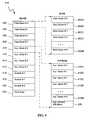
- FIG. 4is a block diagram of a data buffer in accordance with an embodiment of the invention.
- FIG. 1shows an exemplary embodiment of this invention.
- the exemplary system 100contains a DVD interface circuit 102 which operates as an interface between a DVD disc drive 108 and a host 106 .
- the DVD interface circuit 102includes an ATAPI interface 104 , microprocessor 110 , a controller 112 , a memory 114 and a data buffer 116 .
- the memory 114includes a program 118 having a number of executable modules, 120 - 126 , respectively.
- the executable modules, 120 - 126contain submodules configured for various tasks.
- the DVD interface circuit 102processes the request by retrieving requested data block(s) from a DVD associated with a DVD disc drive 108 , storing the retrieved data block(s) in the data buffer 116 , then transferring the data block(s) to host 106 through the ATAPI interface 104 .
- program 118provides instructions to microprocessor 110 and controller 112 by using a number of executable modules, 120 - 126 , and their respective submodules.
- the executable modulesinclude a data retrieve module to retrieve data from the DVD in response to data requests from the host, a data store module to store data into the buffer using a plurality of pointers; and a data transfer module to transfer data to the host via the input/output interface.
- FIG. 2is a block diagram representing the typical components of a DVD data block in an exemplary embodiment.
- the data block 200includes an ECC (Error Correction Code) protection 206 and a data component 204 which includes sixteen data sectors, 208 A- 208 P.
- Each data sector 208 in the data component 204has an ID and an EDC (Error Detection Code) byte.
- FIG. 3illustrates a portion of a controller 112 in an exemplary embodiment.
- the controller 112includes a comparator circuit 306 for locating the target data block and a monitoring circuit 308 for monitoring data block transfer.
- the comparator circuit 306records a target data block ID 306 A to compare to a retrieved data block ID 306 B.
- the retrieved data block ID 306 Bis continuously updated until a retrieved data block ID 306 matches the target ID 306 A.
- the monitoring circuit 308monitors the number of data blocks transferred from a DVD to the data buffer 116 .
- the monitoring circuit 308stops the controller 112 from transferring more data to the data buffer 116 when all of the requested data blocks are transferred.
- the controller 112also includes a series of registers 310 - 316 which record the status of error correction and error checking in the data buffer 116 .
- These series of registersinclude: an ECC status register 310 , an EDC status register 312 , an ID error status register 314 and a title key status register 316 .
- the ECC 310 , EDC 312 and ID error 314 status registerscontain data block status information after each data block has been corrected and checked in the data buffer 116 . Since each DVD data block has one set of ECC protection around it, the ECC register 310 is typically one bit in size. Each of the sixteen sectors of a DVD data block has ID and EDC bytes; thus, typically the EDC register 312 and ID error register 314 contains sixteen bits each. If the DVD is a protected medium (i.e. movie disc), the title key register 316 may be used. The title key register 316 contains the title status of a data block to prevent copying of the data content.
- FIG. 4shows an exemplary embodiment of a data buffer 116 .
- the exemplary data buffer 116has approximately 256 K bytes and is partitioned into four general areas: data areas 402 - 408 , auxiliary areas 410 - 416 , scratch areas 418 - 422 and work area 424 .
- Each data area 402 - 408has a corresponding auxiliary area 410 - 416 .
- Each data areais approximately 32K bytes and is further divided into sectors, 402 A- 402 N.
- each data blockhas sixteen sectors and each sector has 2K bytes.
- Each corresponding auxiliary area 410 - 416is approximately 512 bytes and is divided such that each data sector has a corresponding auxiliary sector 410 A- 410 N in the auxiliary area.
- the auxiliary area 410 - 416may contain any unused portion 426 .
- the data buffer 116has three scratch areas 418 - 422 each of approximately 36K bytes.
- data blocksare first transferred into the scratch areas 418 - 422 to be corrected, then checked and descrambled.
- the data portions of the data sectors 208are separated from the auxiliary portions which includes the ECC protection 206 and the ID and EDC portions of each data sector 208 .
- the data portions of the data sectors 208are moved to data areas 402 - 408 , the auxiliary portions are moved to the corresponding auxiliary areas 410 - 416 and error checking status is latched into registers 310 - 316 , as applicable.
- the controller 12 in the DVD interface circuit 102retrieves the IDs of data blocks near the target data block from a DVD.
- a comparator circuit 306 in the controller 112compares the retrieved data block IDs 306 B (FIG. 3) with the target ID 306 A until the target data block is located. When a match is found between a retrieved ID and the target ID, the comparator circuit 306 allows the controller 112 to automatically begin buffering data block(s) into a data buffer 116 starting from the target data block.
- a monitoring circuit 308 in the controller 112is used to monitor data block transfer and to automatically stop data transfer when all of the requested data blocks have been transferred by the controller 112 .
- a host request indicating the number of data blocks requestedis used by the monitoring circuit to monitor the number of data blocks transferred.
- a numerical value representing the number of requested data blocksis decremented each time a data block is transferred to a data buffer 116 . When the numerical value becomes zero, the controller stops transferring data blocks.
- the numerical valuecan be replaced by other suitable values such as binary numbers.
- the data buffer 116is partitioned into various areas including: the data area 402 - 408 , auxiliary area 410 - 416 , scratch area 418 - 422 , and work area 424 .
- the data buffer 116is partitioned by preprogrammed automatic pointers.
- the data area 402 - 408 in the buffer 116stores the data to be sent to the host 106 .
- the auxiliary area 410 - 416stores the auxiliary data.
- a data blockis first transferred into a scratch area 418 - 422 from a DVD. Error correction and checking of data blocks are performed in the scratch areas 418 - 422 of the data buffer 116 . After error correcting and checking in the scratch area 418 - 422 , the data portion of the data block is moved to the data area 402 - 408 and auxiliary portions are moved into a corresponding auxiliary area 410 - 416 . Error checking status information is latched into registers 310 - 316 which will be explained in more detail below.
- the number of data blocks that can be stored in a data buffer 116can be calculated by subtracting any fixed areas from the total DRAM memory size and dividing the difference into approximately 32K byte data blocks plus a corresponding approximately 512 bytes per auxiliary area. There should not be any partial block areas of less than approximately 32K bytes. Examples of fixed areas include the scratch areas 418 - 422 , work area 424 and approximately 512 bytes of auxiliary area 410 - 416 for each data block. Each of these areas can be located anywhere in the buffer 116 and are accessed by using preprogrammed automatic pointers.
- the data buffer 116has a start data pointer, an end data pointer, an auxiliary start pointer, a current data pointer, a current auxiliary pointer and a pointer for each scratch area.
- Each pointeris capable of automatic wrap around when it reaches the end of a particular area.
- Scratch pointersare programmed to indicate the start of the scratch areas.
- Data pointersare programmed to indicate the start and end of the data area.
- the start of the auxiliary areawhich is typically after the end of the data area, is programmed by the auxiliary start pointers.
- a current data pointeris programmed with an approximately 32K byte increment from the start data pointer.
- a current auxiliary pointeris programmed with the same offset block number as the current data pointer except with a 512 byte increment from the auxiliary start pointer. Once a current data pointer reaches a data end pointer, the current data pointer wraps around the data area automatically to the data start pointer provided that the available data area is at least approximately 32K bytes.
- the auxiliary area 410 - 416typically does not require an end pointer because the current auxiliary pointer wraps around automatically when the current data pointer wraps around.
- the automatic wrap-around featurehelps to maintain a consistent offset between areas in the data buffer 116 . Thus, information in one area of the data buffer (i.e. data area) is prevented from spilling over to anther area of the data buffer (i.e. auxiliary area).
- the work area 424is reserved for storing housekeeping information that may need to be readily available, such as lead-in information for the DVD operation. This information can be transferred to the host through the microcontroller address/data bus.
- the work area 424is configurable by system users to a fixed size based on the amount of data to be stored in the area.
- these data blocksenter the scratch areas 418 - 422 of the data buffer 116 where error correcting and checking processes are performed. If there are too many errors in a data block, the error correcting and checking processes may not be able to finish within the allowed time and the errors may become uncorrectable.
- An uncorrectable error in a data blockmay prevent a transfer of requested data to a host 106 . For example, if the host 106 requests five data blocks and an uncorrectable error occurs in the third data block, the first two data blocks will be transferred and the system may retry the transfer process for the remaining blocks starting from the third block.
- the systemmay still transfer the requested data sectors instead of rejecting the entire data block.
- a data errori.e., EDC or ID error
- the controller in the present inventionwhen locating a target data block, instead of using the microprocessor to check every approximate ID retrieved by the controller as in CD systems, the controller in the present invention locates the target ID automatically without involving the microprocessor. Also, instead of relying on the microprocessor to switch the controller to buffering mode once the target data block is located as in CD systems, the controller in the present invention automatically begins buffering data blocks once the target data block is found.
- the controller in the present inventionkeeps track of the number of requested data blocks and automatically stops transferring data when all requested data blocks have been transferred. Additional advantages of the present invention include: storing portions of data blocks in appropriate sections of the data buffer to facilitate uninterrupted transfer of data to the host; and latching error check status of each data block into a number of registers for quick access before data is transferred to the host.
Landscapes
- Engineering & Computer Science (AREA)
- Signal Processing (AREA)
- Multimedia (AREA)
- Signal Processing For Digital Recording And Reproducing (AREA)
Abstract
Description
Claims (13)
Priority Applications (1)
| Application Number | Priority Date | Filing Date | Title |
|---|---|---|---|
| US09/487,088US6701391B1 (en) | 2000-01-19 | 2000-01-19 | System for stop buffering when a count of stored data blocks from a DVD matches an associated data block number of a requested data block set |
Applications Claiming Priority (1)
| Application Number | Priority Date | Filing Date | Title |
|---|---|---|---|
| US09/487,088US6701391B1 (en) | 2000-01-19 | 2000-01-19 | System for stop buffering when a count of stored data blocks from a DVD matches an associated data block number of a requested data block set |
Publications (1)
| Publication Number | Publication Date |
|---|---|
| US6701391B1true US6701391B1 (en) | 2004-03-02 |
Family
ID=31716074
Family Applications (1)
| Application Number | Title | Priority Date | Filing Date |
|---|---|---|---|
| US09/487,088Expired - LifetimeUS6701391B1 (en) | 2000-01-19 | 2000-01-19 | System for stop buffering when a count of stored data blocks from a DVD matches an associated data block number of a requested data block set |
Country Status (1)
| Country | Link |
|---|---|
| US (1) | US6701391B1 (en) |
Cited By (13)
| Publication number | Priority date | Publication date | Assignee | Title |
|---|---|---|---|---|
| US20030212351A1 (en)* | 2000-01-19 | 2003-11-13 | Hissong James B. | Methods of using high intensity focused ultrasound to form an ablated tissue area containing a plurality of lesions |
| US20040083487A1 (en)* | 2002-07-09 | 2004-04-29 | Kaleidescape, A Corporation | Content and key distribution system for digital content representing media streams |
| US20040088557A1 (en)* | 2002-07-09 | 2004-05-06 | Kaleidescape, A Corporation | Secure presentation of media streams in response to encrypted digital content |
| US20040139047A1 (en)* | 2003-01-09 | 2004-07-15 | Kaleidescape | Bookmarks and watchpoints for selection and presentation of media streams |
| US20050050348A1 (en)* | 2003-08-29 | 2005-03-03 | Ali Corporation | Method for copy protection of DVD recorder |
| US20050086069A1 (en)* | 2003-07-15 | 2005-04-21 | Kaleidescape, Inc. | Separable presentation control rules with distinct control effects |
| US20050182989A1 (en)* | 2004-02-13 | 2005-08-18 | Kaleidescape | Integrating content-laden media with storage system |
| US20090006911A1 (en)* | 2007-06-28 | 2009-01-01 | Mediatek Inc. | Data replacement processing method |
| US20090113269A1 (en)* | 2005-09-26 | 2009-04-30 | Daigo Senoo | Data descrambling apparatus and data descrambling method |
| US7615015B2 (en) | 2000-01-19 | 2009-11-10 | Medtronic, Inc. | Focused ultrasound ablation devices having selectively actuatable emitting elements and methods of using the same |
| US8280051B2 (en) | 2003-01-31 | 2012-10-02 | Kaleidescape, Inc. | Secure presentation of media streams in response to encrypted content |
| US8572104B2 (en) | 2003-04-18 | 2013-10-29 | Kaleidescape, Inc. | Sales of collections excluding those already purchased |
| US9251554B2 (en) | 2012-12-26 | 2016-02-02 | Analog Devices, Inc. | Block-based signal processing |
Citations (9)
| Publication number | Priority date | Publication date | Assignee | Title |
|---|---|---|---|---|
| US5970208A (en)* | 1996-06-21 | 1999-10-19 | Samsung Electronics Co., Ltd. | Device for controlling memory in digital video disk reproducing device and method therefor |
| US6111831A (en)* | 1995-11-15 | 2000-08-29 | Zen Research N. V. | Methods and apparatus for simultaneously reading multiple tracks of an optical storage medium |
| US6119177A (en)* | 1996-12-30 | 2000-09-12 | Samsung Electronics, Co., Ltd. | Digital video disk ROM interfacing apparatus and method thereof |
| US6137763A (en)* | 1998-09-24 | 2000-10-24 | Zen Research N.V. | Method and apparatus for buffering data in a multi-beam optical disk reader |
| US6167551A (en)* | 1998-07-29 | 2000-12-26 | Neomagic Corp. | DVD controller with embedded DRAM for ECC-block buffering |
| US6233649B1 (en)* | 1995-06-26 | 2001-05-15 | Hitachi, Ltd. | Digital signal reproducing method |
| US6332176B1 (en)* | 1998-08-07 | 2001-12-18 | Integrated Memory Logic, Inc. | Autohost controller |
| US6414926B1 (en)* | 1998-12-07 | 2002-07-02 | Shinichi Sugiyama | Optical disc drive |
| US6539518B1 (en)* | 1999-09-10 | 2003-03-25 | Integrated Memory Logic, Inc. | Autodisk controller |
- 2000
- 2000-01-19USUS09/487,088patent/US6701391B1/ennot_activeExpired - Lifetime
Patent Citations (9)
| Publication number | Priority date | Publication date | Assignee | Title |
|---|---|---|---|---|
| US6233649B1 (en)* | 1995-06-26 | 2001-05-15 | Hitachi, Ltd. | Digital signal reproducing method |
| US6111831A (en)* | 1995-11-15 | 2000-08-29 | Zen Research N. V. | Methods and apparatus for simultaneously reading multiple tracks of an optical storage medium |
| US5970208A (en)* | 1996-06-21 | 1999-10-19 | Samsung Electronics Co., Ltd. | Device for controlling memory in digital video disk reproducing device and method therefor |
| US6119177A (en)* | 1996-12-30 | 2000-09-12 | Samsung Electronics, Co., Ltd. | Digital video disk ROM interfacing apparatus and method thereof |
| US6167551A (en)* | 1998-07-29 | 2000-12-26 | Neomagic Corp. | DVD controller with embedded DRAM for ECC-block buffering |
| US6332176B1 (en)* | 1998-08-07 | 2001-12-18 | Integrated Memory Logic, Inc. | Autohost controller |
| US6137763A (en)* | 1998-09-24 | 2000-10-24 | Zen Research N.V. | Method and apparatus for buffering data in a multi-beam optical disk reader |
| US6414926B1 (en)* | 1998-12-07 | 2002-07-02 | Shinichi Sugiyama | Optical disc drive |
| US6539518B1 (en)* | 1999-09-10 | 2003-03-25 | Integrated Memory Logic, Inc. | Autodisk controller |
Cited By (23)
| Publication number | Priority date | Publication date | Assignee | Title |
|---|---|---|---|---|
| US7615015B2 (en) | 2000-01-19 | 2009-11-10 | Medtronic, Inc. | Focused ultrasound ablation devices having selectively actuatable emitting elements and methods of using the same |
| US20030212351A1 (en)* | 2000-01-19 | 2003-11-13 | Hissong James B. | Methods of using high intensity focused ultrasound to form an ablated tissue area containing a plurality of lesions |
| US6936046B2 (en) | 2000-01-19 | 2005-08-30 | Medtronic, Inc. | Methods of using high intensity focused ultrasound to form an ablated tissue area containing a plurality of lesions |
| US7702101B2 (en) | 2002-07-09 | 2010-04-20 | Kaleidescape, Inc. | Secure presentation of media streams in response to encrypted digital content |
| US20040083487A1 (en)* | 2002-07-09 | 2004-04-29 | Kaleidescape, A Corporation | Content and key distribution system for digital content representing media streams |
| US20040088557A1 (en)* | 2002-07-09 | 2004-05-06 | Kaleidescape, A Corporation | Secure presentation of media streams in response to encrypted digital content |
| US8627193B2 (en) | 2003-01-09 | 2014-01-07 | Kaleidescape, Inc. | Bookmarks and watchpoints for selection and presentation of media streams |
| US8225194B2 (en) | 2003-01-09 | 2012-07-17 | Kaleidescape, Inc. | Bookmarks and watchpoints for selection and presentation of media streams |
| US20040139047A1 (en)* | 2003-01-09 | 2004-07-15 | Kaleidescape | Bookmarks and watchpoints for selection and presentation of media streams |
| US8280051B2 (en) | 2003-01-31 | 2012-10-02 | Kaleidescape, Inc. | Secure presentation of media streams in response to encrypted content |
| US8572104B2 (en) | 2003-04-18 | 2013-10-29 | Kaleidescape, Inc. | Sales of collections excluding those already purchased |
| US20050086069A1 (en)* | 2003-07-15 | 2005-04-21 | Kaleidescape, Inc. | Separable presentation control rules with distinct control effects |
| US20050050348A1 (en)* | 2003-08-29 | 2005-03-03 | Ali Corporation | Method for copy protection of DVD recorder |
| US20100146226A1 (en)* | 2004-02-13 | 2010-06-10 | Kaleidescape, Inc. | Integrating Content-Laden Storage Media with Storage System |
| US7689860B2 (en)* | 2004-02-13 | 2010-03-30 | Kaleidescape, Inc. | Integrating content-laden media with storage system |
| US8161319B2 (en)* | 2004-02-13 | 2012-04-17 | Kaleidescape, Inc. | Integrating content-laden storage media with storage system |
| US20120198276A1 (en)* | 2004-02-13 | 2012-08-02 | Kaleidescape, Inc. | Integrating Content-Laden Storage Media with Storage System |
| US20080148096A1 (en)* | 2004-02-13 | 2008-06-19 | Kaleidescape, Inc. | Integrating content-laden media with storage system |
| US7257732B2 (en)* | 2004-02-13 | 2007-08-14 | Kaleidescape, Inc. | Integrating content-laden media with storage system |
| US20050182989A1 (en)* | 2004-02-13 | 2005-08-18 | Kaleidescape | Integrating content-laden media with storage system |
| US20090113269A1 (en)* | 2005-09-26 | 2009-04-30 | Daigo Senoo | Data descrambling apparatus and data descrambling method |
| US20090006911A1 (en)* | 2007-06-28 | 2009-01-01 | Mediatek Inc. | Data replacement processing method |
| US9251554B2 (en) | 2012-12-26 | 2016-02-02 | Analog Devices, Inc. | Block-based signal processing |
Similar Documents
| Publication | Publication Date | Title |
|---|---|---|
| US6470461B1 (en) | Disk drive controller circuit and method for skipping defective and/or undesired sectors | |
| US6604172B2 (en) | Disk array device with selectable method for generating redundant data | |
| US6701391B1 (en) | System for stop buffering when a count of stored data blocks from a DVD matches an associated data block number of a requested data block set | |
| US5832523A (en) | Archiving device and data file server using data file recorded in division over recording media | |
| US9007830B2 (en) | Semiconductor memory device having faulty cells | |
| KR100187829B1 (en) | System and method for skip-sector mapping in a data recording disk drive | |
| US4935825A (en) | Cylinder defect management system for data storage system | |
| EP0660323B1 (en) | Method and apparatus for data storage | |
| US5321826A (en) | Disk control system in which spare disk and master disks are dynamically exchanged | |
| US5412612A (en) | Semiconductor storage apparatus | |
| US5864655A (en) | Managing removable media in raid and rail environments | |
| US20020035668A1 (en) | Information storage system for redistributing information to information storage devices when a structure of the information storage devices is changed | |
| WO2000002121A1 (en) | Method and apparatus for storing diverse data structures | |
| GB2404830A (en) | Data with multiple sets of error correction codes | |
| US5420983A (en) | Method for merging memory blocks, fetching associated disk chunk, merging memory blocks with the disk chunk, and writing the merged data | |
| US7103746B1 (en) | Method of sparing memory devices containing pinned memory | |
| US7840877B2 (en) | Mass storage system and method | |
| US5719885A (en) | Storage reliability method and apparatus | |
| US5664224A (en) | Apparatus for selectively loading data blocks from CD-ROM disks to buffer segments using DMA operations | |
| US20010023496A1 (en) | Storage device and storage subsystem for efficiently writing error correcting code | |
| US10338850B2 (en) | Split-page queue buffer management for solid state storage drives | |
| US6226727B1 (en) | Computer system | |
| US20030177367A1 (en) | Controlling access to a disk drive in a computer system running multiple operating systems | |
| CN116431062A (en) | Data storage method, device, storage medium and system | |
| KR19980047273A (en) | How to Manage Cache on RAID Level 5 Systems |
Legal Events
| Date | Code | Title | Description |
|---|---|---|---|
| AS | Assignment | Owner name:OAK TECHNOLOGY, INC., CALIFORNIA Free format text:ASSIGNMENT OF ASSIGNORS INTEREST;ASSIGNORS:AYAT, MEHRAN;NADERSHAHI, NEDI;REEL/FRAME:010548/0026 Effective date:20000107 | |
| STCF | Information on status: patent grant | Free format text:PATENTED CASE | |
| AS | Assignment | Owner name:ZORAN CORPORATION, CALIFORNIA Free format text:ASSIGNMENT OF ASSIGNORS INTEREST;ASSIGNOR:OAK TECHNOLOGY, INC.;REEL/FRAME:015259/0994 Effective date:20041012 | |
| FPAY | Fee payment | Year of fee payment:4 | |
| FPAY | Fee payment | Year of fee payment:8 | |
| AS | Assignment | Owner name:CSR TECHNOLOGY INC., CALIFORNIA Free format text:ASSIGNMENT OF ASSIGNORS INTEREST;ASSIGNOR:ZORAN CORPORATION;REEL/FRAME:027550/0695 Effective date:20120101 | |
| FPAY | Fee payment | Year of fee payment:12 | |
| AS | Assignment | Owner name:CSR TECHNOLOGY INC., CALIFORNIA Free format text:ASSIGNMENT OF ASSIGNORS INTEREST;ASSIGNOR:ZORAN CORPORATION;REEL/FRAME:036642/0395 Effective date:20150915 | |
| FEPP | Fee payment procedure | Free format text:PAYOR NUMBER ASSIGNED (ORIGINAL EVENT CODE: ASPN); ENTITY STATUS OF PATENT OWNER: LARGE ENTITY | |
| AS | Assignment | Owner name:QUALCOMM INCORPORATED, CALIFORNIA Free format text:ASSIGNMENT OF ASSIGNORS INTEREST;ASSIGNOR:CSR TECHNOLOGY INC.;REEL/FRAME:069221/0001 Effective date:20241004 |