US6701200B1 - Automated custom mold manufacture - Google Patents
Automated custom mold manufactureDownload PDFInfo
- Publication number
- US6701200B1 US6701200B1US10/056,755US5675502AUS6701200B1US 6701200 B1US6701200 B1US 6701200B1US 5675502 AUS5675502 AUS 5675502AUS 6701200 B1US6701200 B1US 6701200B1
- Authority
- US
- United States
- Prior art keywords
- mold
- customer
- cad file
- automatically
- material removal
- Prior art date
- Legal status (The legal status is an assumption and is not a legal conclusion. Google has not performed a legal analysis and makes no representation as to the accuracy of the status listed.)
- Expired - Lifetime, expires
Links
Images


Classifications
- G—PHYSICS
- G06—COMPUTING OR CALCULATING; COUNTING
- G06Q—INFORMATION AND COMMUNICATION TECHNOLOGY [ICT] SPECIALLY ADAPTED FOR ADMINISTRATIVE, COMMERCIAL, FINANCIAL, MANAGERIAL OR SUPERVISORY PURPOSES; SYSTEMS OR METHODS SPECIALLY ADAPTED FOR ADMINISTRATIVE, COMMERCIAL, FINANCIAL, MANAGERIAL OR SUPERVISORY PURPOSES, NOT OTHERWISE PROVIDED FOR
- G06Q30/00—Commerce
- G06Q30/06—Buying, selling or leasing transactions
- B—PERFORMING OPERATIONS; TRANSPORTING
- B22—CASTING; POWDER METALLURGY
- B22C—FOUNDRY MOULDING
- B22C19/00—Components or accessories for moulding machines
- B22C19/04—Controlling devices specially designed for moulding machines
- B—PERFORMING OPERATIONS; TRANSPORTING
- B29—WORKING OF PLASTICS; WORKING OF SUBSTANCES IN A PLASTIC STATE IN GENERAL
- B29C—SHAPING OR JOINING OF PLASTICS; SHAPING OF MATERIAL IN A PLASTIC STATE, NOT OTHERWISE PROVIDED FOR; AFTER-TREATMENT OF THE SHAPED PRODUCTS, e.g. REPAIRING
- B29C33/00—Moulds or cores; Details thereof or accessories therefor
- B29C33/38—Moulds or cores; Details thereof or accessories therefor characterised by the material or the manufacturing process
- B29C33/3835—Designing moulds, e.g. using CAD-CAM
Definitions
- the present inventionrelates to the field of mold making, and particularly to the manufacture of molds, such as for use with injection molding presses, from blocks of metal. More specifically, the present invention relates to software supported methods, systems and tools used in the design and fabrication of molds for custom plastic parts.
- Injection moldingis commonly utilized to produce plastic parts from molds. Companies and individuals engaged in fabricating molds arc commonly referred to as “moldmakers.” In many cases (referred to as “straight pull” injection molding), the mold consists of two metal blocks, one top and one bottom. Most commonly, the metal blocks are high quality machine steel, so the mold will have an acceptably long life. Opposed surfaces of each mold block are machined to jointly produce the required cavity in the shape of the desired part, as well as “shut-off” surfaces sealing the cavity when the mold blocks are pressed together. The line on which shut-off surfaces intersect with the surface of the cavity is called the parting line. The corresponding line on the surface of the part formed by the parting line is called the witness mark.
- partsare made by filling the cavity with molten plastic.
- the mold blocksare separated from each other after solidification of the molten plastic.
- the plastic partnormally sticking after separation to the bottom block, is then ejected by means of ejectors.
- moldmaking arthas a long history of fairly gradual innovation and advancement. Molds are designed pursuant to a specification of the part geometry provided by a customer; in many cases, functional aspects of the plastic part also need to be taken into account. Historically, moldmaking involves at least one face-to-face meeting between the moldmaker and the customer, in which the customer submits detailed part geometry, usually with the aid of drawings, to the moldmaker and outlines the function of the part. Armed with knowledge of injection molding technology, the moldmaker designs the mold corresponding to the drawings of the part. In particular, the moldmaker orients the part to enable a straight pull mold separation, splits its surface into two areas separated by a suitable parting line, and replicates these areas in the top and bottom blocks.
- the moldmakerdetermines the location and shape of the shut-off surfaces and enlarges the dimensions of the cavity relative to the desired part as necessary to account for shrinkage of the plastic material.
- the moldmakerdetermines the size and position of one or more gates and runners to provide an adequate flow path for the molten plastic shot into the cavity. Sizes and locations of openings for ejection pins are also selected by the moldmaker.
- the machining operations to be performed to fabricate the designed moldare determined by the moldmaker.
- the moldmakerthen runs various cutting tools, such as endmills, drills and reams, to machine the basic cavity, shut-off surfaces, runners, gates and ejector pin openings in blocks of metal.
- the moldmakermay also design and machine electrodes, and then perform electro-discharge machining (“EDM”) of the mold blocks.
- EDMelectro-discharge machining
- the moldmakerthen outfits the mold blocks with ejection pins and prepares the mold assembly for use in the injection molding press.
- the moldmakermakes numerous design choices pertaining to the geometric details of the cavities to be machined as well as to the tools to be used for machining.
- CAD/CAMComputer-Aided Manufacturing
- CAD/CAM packagesallow designers and CNC machinists to work with geometrically complex parts, they are still far from completely automating the designer's work. Rather, these packages provide an assortment of software-supported operations that automate many partial tasks but still require that numerous decisions be made by the user to create the design and generate machining instructions.
- CAD/CAM packagesusually facilitate such decisions by means of interactive visualization of the design geometry and machining tools. This makes software applicable to a wide variety of tasks involving mechanical design and machining operations.
- the downside of such versatility, when applied to moldmaking,is that it results in long and labor intensive working sessions to produce mold designs and CNC machining instructions for many custom parts, including parts lending themselves to straight pull molding.
- the present inventionis a method and system of automated, custom mold manufacture for a part.
- a collection of information of standard tool geometries indicating surface profiles machinable by each of the standard tool geometriesis created and stored.
- a customersends a CAD file for the part to be molded to the system.
- the systemassesses the CAD file to determine various pieces of mold manufacturing information.
- the systemdetermines whether the part meets one or more acceptability criteria for the method of mold manufacture chosen.
- the systemsends a file to the customer graphically indicating which portions of the part need modification to be manufacturable in accordance with the method of mold manufacture chosen.
- the systemprovides the customer with a quotation of the cost to manufacture the mold or a number of parts.
- the preferred systemgeometrically assesses the customer's part and automatically selects appropriate tools and computes tool paths for mold manufacture.
- the preferred systemthen generates CNC machining instructions to manufacture the mold, and the mold is manufactured in accordance with these instructions.
- FIG. 1is a perspective view of an exemplary “cam” part desired by a customer.
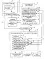
- FIG. 2is a flow diagram of the preferred method followed by the present invention to manufacture the mold for the exemplary “cam” part.
- FIG. 3is a representational view conceptually showing failure of straight pull in a y-axis direction.
- FIG. 4is a representational view conceptually showing acceptance of straight pull in a z-axis direction.
- FIG. 5is an elevational view of a standard endmill.
- FIG. 6is an exemplary product deviation file of the exemplary part of FIG. 1 .
- FIG. 7is a computer screen shot of a perspective view showing the selected tool paths of the standard endmill of FIG. 4 in fabricating the mold for the exemplary part of FIG. 1 .
- FIG. 8is a perspective view showing the parting line, the shut-off surfaces, and the ejection pin locations for the exemplary part of FIG. 1 .
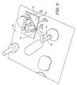
- FIG. 9is a perspective view showing sprews, runners, gates and ejection pins for the mold for the exemplary part of FIG. 1 .
- FIG. 1represents a “cam” part 10 designed by the customer.
- the cam 10is custom-designed (i.e., not a staple article of commerce) by or for this particular customer, the cam 10 includes numerous features, none of which have commonly accepted names.
- the customermay in fact have no name or may have a very different name for any of these features.
- FIG. 2is a flow chart showing how the present invention is used to manufacture the customer's part.
- the first stepinvolves a Customer Data Input module 30 .
- the starting input for the present inventionis the CAD part design file 32 , provided by the customer from the customer's computer 34 .
- the CAD part design file 32provided by the customer from the customer's computer 34 .
- IGESInitial Graphics Exchange Specification
- the present inventionaccepts IGES, STL or various other formats, and is compatible with all the commercial CAD products currently in use.
- the present inventionallows the customer to provide the CAD file 32 without a face-to-face meeting. Such communication could occur through a mailed computer disk or through a dial-up modem site.
- an address on a global communications networksuch as the internet 36 is configured to receive customer CAD files 32 . While the address could be a simple e-mail address, the preferred address is a website on the world-wide-web, configured to receive a CAD file 32 from a customer for the part to be molded.
- the “web-centric” customer interfacepreferably include a part submission page as part of the Customer Data Input module 30 , which allows the customer to identify which standard CAD/CAM format is being used for the part drawings.
- the customer's CAD file 32may be evaluated with an initial program which determines which type of standard CAD/CAM format is being used by the customer. If the CAD file 32 transmitted by the customer does not conform to a recognized standard CAD file format so as to be readable by the software of the present invention, the customer data input module returns an error message to the customer.
- the customer's CAD file 32entirely defines the part 10 .
- the next step in the processis performed by a geometry analyzer module 38 , which assesses the geometry of the customer's part 10 using a set of acceptability criteria 40 , 42 , 44 , 46 .
- This geometry analyzer module 38is used to determine whether the mold for the part defined by the customer's CAD file 32 can be inexpensively manufactured in accordance with the present invention.
- acceptability criteriacan be used, depending upon the software and manufacturing capabilities used in automated manufacturing of the mold.
- the first preferred acceptability criterion 40is whether the part can be molded in a straight pull mold. If desired, an individual may view the customer's CAD file 32 , either through a printout drawing or on-screen, to visually inspect and determine whether the part can be manufactured in a straight pull mold.
- the programautomatically identifies whether the part can be manufactured in a straight pull mold.
- Automatic “straight pull” manufacturability identification 40involves selecting an orientation of the part in the customer's CAD file 32 . Customers typically draw parts oriented with an x-, y- or z- axis which coincides with the most likely straight pull direction. FIGS. 3 and 4 represent an example of this.
- the cam 10is solid modelled in the y-direction as a plurality of parallel line segments extending in the y-direction as shown in FIG. 3 .
- the geometry analyzer module 38then considers each line in the solid modeling, to determine whether the line is continuous and intersects the part surface profile only at a single beginning and a single ending.
- line 48is a first line which fails this test, as it intersects the cam 10 three times: once through the part outline flange 12 and twice on the sides of the 60° corner hole 24 .
- the y-direction orientation of this part 10thus fails to permit straight pull mold manufacturability 40 .
- the cam 10is next solid modelled in the z-direction as a plurality of parallel line segments extending in the z-direction as shown in FIG. 4 .
- the geometry analyzer module 38again considers each line in the solid modeling, to determine whether the line is continuous and intersects the part surface profile only at a single beginning and a single ending. As shown here in FIG. 4, all the line segments meet this test 40 .
- the cam 10passed the test 40 in the z-direction, it is thus determined that the part 10 can be oriented such that the z-direction is the straight pull direction.
- the cam 10can be formed with a straight pull mold with the straight pull direction coinciding with the z-direction as drawn.
- the “straight pull” manufacturability identification 40can be terminated once it is determined that at least one orientation of the part 10 exists which can be manufactured with a straight pull mold.
- additional testscontinue to be automatically run by the geometry analyzer module 38 to confirm the best orientation of the part 10 which can be manufactured with a straight pull mold. For instance, a similar x-direction test is run, which this cam part 10 fails similar to the z-direction test.
- additional orientational testscan be run, with the parallel lines in the solid modeling run at angles to the x-, y- and z-directions selected in the customer's CAD file 32 .
- the present inventionfurther reviews the part design using a second acceptability criterion 42 , of whether the mold geometry can be formed through machining with a standard set of CNC machining tools.
- This second acceptability criterion 42involves determining which tools are available, what are limitations in using the available tools, and defining areas of the mold (if any) which cannot be machined with the available tools. Because this second acceptability criterion 42 has significant overlap with generating the automated set of CNC machining instructions in the tool selection and tool path computation module 68 , it is discussed in further detail below.
- the preferred standard CNC machining toolsinclude a collection of standard-sized endmills, standard-sized reams and standard-sized drills.
- any grooves in the moldwhich correspond to any ribs in the part, must have an aspect ratio which permits at least one of the standard CNC machining tools to reach the depth of the groove.
- FIG. 5depicts the profile of a standard 1 ⁇ 4 inch diameter ball endmill 50 .
- This endmill 50has a cutting depth 52 of slightly less than 2 inches limited by a collet 54 . If a 1 ⁇ 4 inch thick groove in the mold has a height of 2 inches or more, then the standard 1 ⁇ 4 inch diameter endmill 50 cannot be used to form the groove portion of the cavity.
- the aspect ratios of standard endmillsare based upon the strength of the tool steel (so the tool 50 won't easily break in use), and follow a similar aspect ratio curve. That is, all endmills which are less than 1 ⁇ 4 inch in diameter are shorter than the standard 1 ⁇ 4 inch diameter ball endmill 50 . All endmills which are longer than 2 inches are wider than 1 ⁇ 4 inch in diameter.
- the geometry analyzer module 38includes analysis 42 run against the customer's CAD file 32 , to conceptually compare the part shape against collected geometric information of a plurality of standard tool geometries, such a standard endmills. For the cam 10 , all of the CAD file 32 passes except for the rib 22 , which is too thin and long.
- the preferred CNC machining criterion 42further considers aspect ratios of grooves relative to the parting line of the mold. Because endmills can be used downward in the bottom half (cavity) of the mold and upward in the top half (core) of the mold, aspect ratios of features which contain the parting line can be twice that of aspect ratios of features which do not contain the parting line. That is, groove depth is measured relative to the lowest adjacent extending surface on the half of the mold in which the groove is machined. In the cam 10 , for instance, the inside edge of the part outline flange 12 does not intersect the parting line, because the parting line extends along the inside edge of the partial web 28 .
- the depth of the part outline flange 12is therefore measured relative to the adjacent extending surface, the partial web 28 .
- the aspect ratio determined by this depth of the part outline flange 12 relative to the thickness of the part outline flange 12must be within the aspect ratio of at least one tool in the standard set.
- the outer edge of the part outline flange 12has no adjacent extending surface and intersects the parting line. Because the parting line separates the outer edge of the part outline flange 12 into the two mold blocks, the depth of the outer edge of the part outline flange 12 relative to its thickness can be up to twice the aspect ratio of at least one tool in the standard set.
- the CNC machining criterion 42runs similar programming analysis to verify that each corner of the part 10 has a sufficient radius of curvature to permit machining by one of the standard CNC machining tools. For instance, the CNC machining criterion may limit the minimum radius of outside corners of the part to no less than 1 ⁇ 2 the minimum wall thickness. If the CAD file 32 fails either due to having too deep of grooves or having too tight of corners, the part fails the CNC machining criterion 42 , and the customer must be informed. Computer programmers will recognize that, once the acceptability criteria 42 are defined to include a determination of whether groove depths and/or corner radii of the part permit standard CNC machining, there are many equivalent programming methods to apply this acceptability criterion to the customer's CAD file 32 .
- the geometry analyzer module 38further reviews a third acceptability criterion 44 , of whether the mold geometry can be formed in aluminum or in an aluminum-based alloy. That is, a design parameter imposed upon the preferred system is that the mold be manufacturable from standard aluminum-based mold block stock.
- Aluminumis selected for cost reasons, with a primary cost savings in that aluminum is more quickly machined than steel, and a secondary cost savings in that the aluminum blocks themselves are less expensive than steel.
- aluminumis not as strong as steel, and excessively thin structures of aluminum will not withstand the forces imparted during injection molding. Accordingly, the program looks at the mold to determine whether any portions of the mold are too thin.
- the cam 10has one thin recess, the notch 20 , which if sufficiently thin and deep fails this criterion. That is, as the cam 10 was designed by the customer, the mold for the cam 10 cannot be formed of aluminum and withstand the forces of injection molding. Computer programmers will recognize that, once the acceptability criteria 44 are defined to include a determination of whether the mold can be formed of aluminum, there are many equivalent programming methods to apply this acceptability criterion to the customer's CAD file 32 .
- the customer data input module 30may permit the customer to select from any of the following standard plastics: ABS (natural), ABS (white), ABS (black), ABS (gray—plateable), Acetyl/Delrin (natural), Acetyl/Delrin (black), Nylon (natural), Nylon (black), 13% glass filled Nylon (black), 33% glass filled Nylon (black), 33% glass filled Nylon (natural), 30% glass filled PET/Rynite (black), Polypropylene (natural), Polypropylene (black), Polycarbonate (clear), Polycarbonate (black), Ultem 1000 (black), Ultem 2200 (20% glass filled) (black), Ultem 2300 (30% glass filled) (black).
- the programfurther reviews a fourth acceptability criterion 46 , of whether the mold geometry can be adequately injection molded with the plastic material selected by the customer.
- This acceptability criterion 46involves an assessment of whether the mold contains areas that will not shrink uniformly for the selected plastic material, and whether gating can be readily machined into the mold, to result in an acceptable flow path for the plastic which will be met at an attainable mold temperature and pressure so the shot adequately and uniformly fills the cavity.
- the partmay need to fit within a maximum projected area, as viewed through the straight-pull axis, of 50 sq. in. (400 sq. cm). Similarly, the part may need to be smaller than a maximum part volume, such as a maximum volume of 18 cu. in. (200 cc).
- the customer's CAD file 32fails one or more acceptability criteria 40 , 42 , 44 , 46 . If desired, the failure to meet any acceptability criteria 40 , 42 , 44 , 46 , may be communicated through a telephone call. However, preferably the program automatically generates a computer message which is transmitted to the customer, such as an e-mail. The preferred acceptability failure message indicates the nature of the failure. In the most preferred embodiment, the program includes a proposed modification CAD file communication module 56 .
- the proposed modification CAD file communication module 56involves several different steps. First, information is stored about each way in which the part 10 fails an acceptability criterion 40 , 42 , 44 , 46 . For instance, not only will information be stored that the cam 10 fails because the rib 22 is too thin and long and because the notch 20 is too deep and thin, but information is also stored about the closest rib and notch which would pass the acceptability criteria 42 , 44 . That is, by making the rib 22 slightly thicker, the rib 22 can be formed in the mold with standard CNC endmills. By making notch 20 slightly thicker, the aluminum mold will withstand the forces of injection molding.
- the proposed modification CAD communication module 56then generates a modified CAD file 58 , which distinguishes between the portions of the part geometry which pass all acceptability criteria 40 , 42 , 44 , 46 and the portions of the part geometry which fail at least one acceptability criteria 40 , 42 , 44 , 46 .
- FIG. 6A drawing from the proposed modification CAD file 58 is shown as FIG. 6 .
- the proposed modification CAD file 58highlights the closest approximations 60 , 62 , relative to remaining unaltered portions of the cam design part surface profile 10 which pass all acceptability criteria 40 , 42 , 44 , 46 . Highlighting may be done through different line formats, different colors, etc. For instance, using one of predefined color coding schemes, colors are assigned to representative areas to show the identified association of the machinable points and to indicate the lack of appropriate tool.
- the part geometry supplemented by the color datais preferably placed in a file 58 using one of the standard graphical formats suitable for rendering interactively manipulated three-dimensional views of the part 10 .
- the file 58 together with the legend explaining the color coding scheme usedcan be sent or otherwise made available to the customer for interactive viewing, possibly with additional comments.
- the proposed modification CAD communication module 56then automatically transmits the proposed modification CAD file 58 to the customer, so the customer can view the changes required for inexpensive manufacture of the mold.
- a mold for the cam 10 as originally designed by the customercould be formed, but it would be formed of steel rather than aluminum and the rib portion 22 of the mold would be burned by EMD.
- the present inventionis configured based upon the capabilities of the moldmaking shop. If the moldmaking shop can handle CNC machined aluminum molds as well as EMD steel molds, then the program may assess acceptability criteria for both types of processes. If the customer's CAD file 32 fails at least one acceptability criteria for the less expensive method of mold manufacture, then a first proposed modification CAD file 58 may be generated and transmitted to the customer. If the customer's CAD file 32 passes all acceptability criteria for the more expensive method of mold manufacture, this information may be transmitted to the customer as well.
- the present inventionthus provides a computerized method for fast identification of the mold manufacturability issues.
- mold manufacturability issuesare automatically identified and communicated to the customer.
- the three-dimensional graphical representation 58 of mold manufacturability issuesis very convenient and considerably simplifies communication of such issues to the customers.
- the geometry analyzer module 38 in tandem with the proposed modification CAD communication module 56are valuable tools for the design engineer. These modules 38 , 56 can be used during the development process to guide the design toward a part 10 that can be manufactured quickly and economically, whether or not it is quoted and manufactured in accordance with the rest of the preferred system.
- the next part of the preferred systemis the quoting module 64 .
- quotingmay be performed the prior art way, by having an experienced moldmaker review drawings of the customer's part 10 and meticulously consider what may be involved in making the mold. More preferably however, the quoting module 64 automatically generates a quotation 66 for the mold, and transmits the automatically-generated quotation 66 to the customer 34 .
- the programTo automatically generate a quotation 66 , the program must assess one or more cost parameters which are indicative of the real costs which will be incurred to form the mold.
- the most basic cost parameterspreferably considered involve the machining actions which will be used to form the mold. That is, the preferred quotation 66 varies based upon computer analysis by the quoting module 64 of at least one indicator of mold manufacture time. Automatic determination of machining actions and/or other material removal steps in the tool selection and tool path computation module 68 is further detailed below. If machining actions are automatically determined, then the quoting module 64 automatically assesses the determined machining actions to arrive at a quotation 66 .
- a primary indicator of overall mold manufacture timeis how long it takes to CNC machine the mold.
- a primary indicator of how long it takes to CNC machine the moldis the number of steps in the series of CNC machining instructions.
- the automatic quotation 66may be based in part or in full on the number of steps in the series of CNC machining instructions.
- the quoting module 64stores information about a rate of material removal associated with each of the different material removal steps.
- the preferred quoting module 64automatically identifies an estimated duration of material removal required for each discrete portion of the part surface profile.
- the automatic quotation 66may be based in part or in full on a total of estimated durations of material removal.
- the Customer Data Input module 30may permit the customer to select a special surface finish, such as a polished finish, matte (similar to EDM), or special etched textures. If so, the automatic quotation may further vary based upon the difficulty in applying the selected special surface finish to the mold.
- a special surface finishsuch as a polished finish, matte (similar to EDM), or special etched textures.
- the time required during material removalis only a portion of the time required for CNC machining. Additional time is required to change from one tool to another. For instance, standard CNC machines may include spots for 10 to 40 tools. Changing among these 10 to 40 tools takes additional time. Further, a portion of the cost of CNC machining is based upon the expense and wear rate of the tool 50 . Some tools are more expensive than others, and some tools need to be replaced more frequently than others. Even more time and cost may be incurred if a special, custom or delicate tool is required for some material removal steps. As a separate, more accurate enhancement, the quoting module 64 may consider the number and type of tools used in the selected material removal steps.
- a separate iteration which improves the accuracy of the quotation 66involves having the quoting module 64 consider the parting line and corresponding shutoff surfaces of the mold.
- simple moldswhich can be formed with an x-y planar parting line and shutoff surfaces are relatively inexpensive. A major portion of the expense of some molds may involve the time required to machine the parting line and corresponding shutoff surfaces which are not x-y planar.
- the automatic quoting module 64may consider the complexity in forming the parting line and corresponding shutoff surfaces. Alternatively, the quoting module 64 may ignore the complexity of building shut-off surfaces that are necessary in the full-blown mold design, particularly if the design of the shutoff surfaces is not automated.
- the preferred quoting module 64further accounts for the mold block area required for the part 10 .
- a further separate indicator of mold manufacture timeinvolves ribbing and tightly radiused corners, as discussed previously with regard to acceptability criteria 40 , 42 , 44 , 46 in the geometry analyzer module 38 . Deep grooves in the mold and sharper corners take more time to machine.
- the preferred quoting module 64further automatically assesses and accounts for the amount, depth and steepness of ribbing required for the part 10 .
- a further separate indicator of mold manufacturing difficulty and timedepends upon whether and which features cannot be standardly CNC machined, but rather require EDM.
- the existence of any required EDM material removalwill increase the cost of the mold.
- Each feature which requires EDMwill increase cost, and more so if the EDM feature is deep enough to require, because of electrode wear, multiple EDM electrodes.
- the preferred quoting module 64identifies any different discrete portions of the part surface profile which are associated with different electrodes for EDM, and the automatically generated quotation 66 varies based upon the estimated number of electrodes required.
- the preferred quoting module 64quotes piece prices. Different piece price quotations 66 may be given, for instance, for 10, 100, 1000, or 10000 parts. In addition to the cost of the mold, the primary cost considerations for piece price quotations 66 depend upon what type of plastics material is used, and how much of it.
- the preferred quoting module 64automatically provides piece price quotations, which involve the cost of the mold and further vary based upon the volume of the part and the plastic material selected by the customer for injection molding.
- the quoting module 64communicates the quotation 66 to the customer, preferably through the internet 36 such as through the website (if real-time quotation is attained) or through a responsive e-mail to the customer's computer 34 . The customer may then accept the quotation 66 through the same medium.
- the quoting module 64is another important tool which can be used by design engineers separately from other facets of the preferred system, such as to compare different design alternatives. Since it is fast and easy, instant online quoting is a powerful tool for budgeting and comparing design alternatives during the development process. Design engineers may use online quoting several times in the design of a single part and online quoting will become a very important part of their design process.
- the next part of the preferred embodimentinvolves the tool selection and tool path computation module 68 .
- the tool selection and tool path computation module 68may be activated upon receipt of an accepted quotation 66 , but more preferably operates in conjunction with the quoting module 64 as discussed earlier.
- the task of the tool selection and tool path computation module 68is to determine what tools to use and what tool paths should be used with those tools to efficiently manufacture the mold for the part specified by the CAD file 32 of the customer.
- the predicted shrinkage 70 of the plastic material upon solidificationis applied to the CAD file 32 .
- the dimensionsare increased in accordance with known shrinkage factors.
- Subsequent calculations in the tool selection and tool path computation module 68are based upon the size of the cavity (before shrink, as determine by a shrinkage factor 70 ) rather than size of the part 10 (after shrink).
- Mold layout 72is the process of assigning and locating one or more core/cavities onto a standardized mold base. For small, simple parts, two or more identical cavities may be machined into a standard sized mold block. A family mold contains more than one unique part, and is often used to reduce tooling cost for a group of parts that are used together. A multi-cavity mold usually refers to a mold with multiple copies of the same part. This approach is commonly used to reduce per part costs when expected production volume will be significant. Either or both approaches may be utilized using the present invention. Selecting one of several standard mold base sizes determines the size of the raw block of aluminum from which the mold will be formed. If the automatic quoting module 64 is used, information about which standard size of mold block is to be used and the number of cavities in the mold as selected in mold layout 72 is fed back to the automatic quoting module 64 .
- the parting line and corresponding shutoff surfacesare selected 74 .
- the parting line and corresponding shutoff surfacesshould be oriented with respect to the part to permit straight pull of the first half and the second half in a straight-pull z-direction during molding of the part. Again, selection of the parting line and corresponding shutoff surfaces could be performed manually by an experienced moldmaker. In the preferred embodiment, the parting line and corresponding shutoff surfaces are automatically oriented 74 with respect to the part 10 as follows.
- the CAD file 32is assessed to automatically determine all edge surfaces which extend parallel to the straight-pull z-direction. For a moment, the parallel edge surfaces are excluded from the determination, as determining the parting line for the other portions of the part 10 is relatively easy. If an edge surface does not extend parallel to the straight-pull z-direction, then the parting line is at the height of the greatest a real extent of the part. Thus, the parting line/shutoff surface portion 74 of the tool selection and tool path computation module 68 automatically defines parting line segments which extend along the uniquely (non z-direction) extending greatest periphery of the part 10 .
- the cam 10has no uniquely (non z-direction) extending periphery of the part, as the part outline flange 12 , the circular opening 14 , the two rotation pins 16 , the non-circular opening 18 , the notch 20 , the 60° corner hole 24 , the 30° corner hole 26 , and the partial web 28 all provide edge surfaces which extend in the z-direction.
- the parting line selection routine 74uses the CNC machining criterion 42 and verifies potential z-direction heights of the parting line segments within the parallel edge surfaces, to assure that the selection of the parting line comports with the desired machinability of the mold. For instance, if tool 50 is being used to machine the bottom mold block at a parallel edge surface of the part outline flange 12 , and if tool 50 has a cutting depth 52 of two inches, then the parting line segment must be within the bottom two inches of the parallel edge surface of the part outline flange 12 .
- the parting line selection routine 74can use any of several optimization routines.
- the parting line segments within the parallel edge surfacessimply connect the unique and CNC defined parting line segments.
- the parting lineshould be designed to be no steeper than 5-10 degrees.
- a smoothing routineis used to define curved parting line segments within the parallel edge surfaces.
- a second derivative of the parting linei.e., the instantaneous change in slope of the parting line
- shutoff surfaces within the moldare automatically determined in much the same way.
- the shutoff surfacesare those surfaces where the mold halves will contact each other when the mold is closed.
- the shutoff surfacesby definition include the parting line. If the parting line is planar, with no holes inside the part, the shutoff surface is defined to be coplanar with the parting line.
- the circular opening 14 and the non-circular opening 18also represent areas of contact between the shutoff surfaces for the two parts of the mold.
- the parting line around the part outline flange 12 , the parting line around the circular opening 14 and the parting line around the non-circular opening 18can each be planar.
- the shutoff surface at the circular opening 14can be planar, as can the shutoff surface at the non-circular opening 18 .
- Defining the shutoff surfacescan be very complex in the case of a part with a highly articulated parting line and complex internal telescoping shutoffs.
- the preferred embodiment 74optimizes the selection of the shutoff surfaces. To the extent possible, the shut-off surfaces should be designed to be no steeper than 5-10 degrees. While a straight-line routine could be used, the preferred embodiment used a three-dimensional smoothing routine.
- the preferred smoothing routinescreate a parting line shutoff surface which is mathematically complex, and virtually impossible to hand machine.
- the complex surfaceis mathematically defined, and translated, into CNC machining instructions.
- the mathematical complexity of the curveis not particularly important. What is important in the CNC machining instructions is that the shut off surfaces are as smooth as possible, and thus can be formed with the largest tool(s) possible and at the fastest material removal rates.
- Automatic selection 74 of the parting line and corresponding shutoff surfacesthus provides for: (a) a fast assessment of acceptability criterion 42 ; (b) a fast quotation 66 ; (c) a fast generation of CNC machining instructions 76 ; and (d) a fast CNC machining operation 78 to fabricate the mold.
- the preferred methoduses the geometry analyzer module 38 to automatically determine the tools and material removal steps required to form the cavity or cavities.
- the cavityis split in two parts, one for the top mold block and the other for the bottom mold block.
- the shutoff surfaceswhich are defined identically but opposite for the two mold blocks, the cavity obviously may have different top and bottom shapes.
- the geometry analyzer module 38For each of the two cavity surfaces, the geometry analyzer module 38 generates a cloud of points dense enough to represent the part geometry with acceptable tolerance. For each point in the cloud, the geometry analyzer module 38 traverses the set of machining tools available.
- a collection of information of standard tool geometries and surface profiles machinable by each of the standard tool geometriesis created and stored in the program 38 . Because we have already defined the system constraints to include straight-pull manufacturability 40 , the preferred collection of information is only considered in the CNC machine with the mold block oriented relative to the tool in the straight-pull z-direction. This stored information is considered by the geometry analyzer module 38 to determine which tools are available to machine a small vicinity of each point without gouging more distant parts of the partial surface either with the tip or shank of the tool 50 or with the collet 54 holding the tool 50 . The tool information is traversed starting from the most efficient (fastest material removal, lowest cost) tool and going in the direction of decreasing tool efficiency. The traversal is stopped when several tools that can machine the current point without gouging are found. The association between the points and the identified most effective non-gouging tools is stored in the memory.
- the geometry analyzer module 38uses a tool selection optimization routine 80 which selects the most efficient tool.
- the collection of machinable pointsshould be machined with as few tool changes as possible, but still at the highest rate of material removal.
- the tool selection and tool path computation module 68automatically identifies and locates discrete machinable portions of the part surface profile which can be machined with a single tool 50 , and records the most efficient tool path for that tool 50 .
- FIG. 7is a “screen-shot” representing a portion of an optimized tool path 82 generated so as much of the cavity 84 as possible for the cam 10 can be machined by CNC machining with the 1 ⁇ 4 endmill 50 .
- the preferred tool selection and tool path computation module 68determines the other portions of the mold 86 as well. In particular, the preferred tool selection and tool path computation module 68 automatically identifies 88 sizes and locations of ejector pins 90 , as shown in FIG. 8 . Ejector pins 90 are used to push the part 10 out of the mold 86 after it has been formed. In general, ejector pin selection 88 considers the profile of the mold 86 to determine the deepest locations which provide significant surface area extending perpendicular to the straight-pull z-direction. The ejector pin selection routine 88 centers ejector pin locations on these flat surfaces, and sizes the ejector pins 90 by selecting the largest standard size that will fit within each flat surface.
- the preferred tool selection and tool path computation module 68also automatically identifies 92 sizes and locations of runners 93 and gates 94 , as shown in FIG. 9.
- a gate 94is the place on the mold 86 where the plastic is injected into the mold cavity 84 as a part is being produced.
- a runner 93is the path on the mold 86 where the molten plastic travels to get from the molding machine to the gate(s) 94 and into the part cavity 84 .
- the sizes of runners 93 and gates 94are selected 92 from knowledge of standard cutting tool sizes, based upon the plastic material selected by the customer, the volume of the part, and the known flow constraints of that plastic material.
- the locations of the gates 94are generally selected 92 to connect to the part 10 on a surface which extends parallel to the z-direction, and to minimize seam lines in the part 10 based upon flow geometry.
- the locations of the runners 93are generally selected 92 to be as straight as possible from the sprue location 96 to the gates 94 .
- the preferred methodincludes a CNC instruction generation module 100 which generates the detailed instructions 76 that will be used by the CNC milling equipment to cut the mold 86 from a raw block of aluminum.
- the CNC instruction generation module 100generates a series of CNC machining instructions 76 corresponding to machining the mold 86 with the selected tools and computed machining actions. For instance, the CNC instruction generation module 100 may generate a “g-code” program containing a set of instructions 76 for CNC milling machines.
- the shape of the cavity 84 as machined in the mold blockcan be visualized with one of the g-code viewers developed for up-front visual verification of machining under the control of g-code programs, and the shape of the cavity 84 can be visually compared with drawings of the part 10 .
- CNC machining instructions 76are generated to machine ejector pin locations 90 , sprues 96 , runners 93 , gates 94 etc. into the mold blocks.
- the final step in the preferred processis machining 78 the mold 86 .
- the shutoff surfaces 98are machined into the mold blocks with the selected tools and computed machining actions and via the computer generated series of CNC machining instructions 76 .
- the cavity 84is likewise machined into the first and second halves of the mold 86 .
- Locations for ejector pins 90are machined into the first and second halves of the mold 86 via the computer generated series of CNC machining instructions 76 , as are runners 93 and gates 94 .
- the quotation 66involve a piece price quotation
- the number of pieces ordered by the customerare run in an injection mold press.
- the piecesare shipped back to the customer.
- the customeris billed in accordance with the quotation 66 .
- the present inventionallows mass production techniques to be used in the moldmaking process, even though every mold is custom designed, custom machined and different.
Landscapes
- Engineering & Computer Science (AREA)
- Business, Economics & Management (AREA)
- Finance (AREA)
- Mechanical Engineering (AREA)
- Accounting & Taxation (AREA)
- Development Economics (AREA)
- Manufacturing & Machinery (AREA)
- Economics (AREA)
- Marketing (AREA)
- Strategic Management (AREA)
- Physics & Mathematics (AREA)
- General Business, Economics & Management (AREA)
- General Physics & Mathematics (AREA)
- Theoretical Computer Science (AREA)
- Moulds For Moulding Plastics Or The Like (AREA)
Abstract
Description
Claims (23)
Priority Applications (6)
| Application Number | Priority Date | Filing Date | Title |
|---|---|---|---|
| US10/056,755US6701200B1 (en) | 2001-12-27 | 2002-01-24 | Automated custom mold manufacture |
| US10/325,286US6836699B2 (en) | 2001-12-27 | 2002-12-19 | Automated quoting of molds and molded parts |
| US10/970,130US7590466B2 (en) | 2001-12-27 | 2004-10-21 | Automated quoting of molds and molded parts |
| US11/035,648US7496528B2 (en) | 2001-12-27 | 2005-01-14 | Automated quoting of molds and molded parts |
| US11/586,379US7840443B2 (en) | 2001-12-27 | 2006-10-25 | Automated quoting of CNC machined custom molds and/or custom parts |
| US12/354,546US8140401B2 (en) | 2001-12-27 | 2009-01-15 | Automated quoting of molds and parts from customer CAD file part data |
Applications Claiming Priority (2)
| Application Number | Priority Date | Filing Date | Title |
|---|---|---|---|
| US34418701P | 2001-12-27 | 2001-12-27 | |
| US10/056,755US6701200B1 (en) | 2001-12-27 | 2002-01-24 | Automated custom mold manufacture |
Related Child Applications (1)
| Application Number | Title | Priority Date | Filing Date |
|---|---|---|---|
| US10/325,286Continuation-In-PartUS6836699B2 (en) | 2001-12-27 | 2002-12-19 | Automated quoting of molds and molded parts |
Publications (1)
| Publication Number | Publication Date |
|---|---|
| US6701200B1true US6701200B1 (en) | 2004-03-02 |
Family
ID=31720002
Family Applications (1)
| Application Number | Title | Priority Date | Filing Date |
|---|---|---|---|
| US10/056,755Expired - LifetimeUS6701200B1 (en) | 2001-12-27 | 2002-01-24 | Automated custom mold manufacture |
Country Status (1)
| Country | Link |
|---|---|
| US (1) | US6701200B1 (en) |
Cited By (75)
| Publication number | Priority date | Publication date | Assignee | Title |
|---|---|---|---|---|
| US20030154101A1 (en)* | 2002-02-13 | 2003-08-14 | Archibald Kevin Carl | System, methods, and medium for facilitating providing a quote |
| US20030229599A1 (en)* | 2002-05-15 | 2003-12-11 | Michikazu Sakurai | Injection-molding cost estimation system |
| US20040140579A1 (en)* | 2001-06-08 | 2004-07-22 | Tetsuo Uwaji | Method of analyzing injection molding conditions |
| US20050021171A1 (en)* | 2003-07-25 | 2005-01-27 | Luo Sheng Chi | System and method for management of mold design and production |
| US20060173566A1 (en)* | 2005-02-01 | 2006-08-03 | The Protomold Company, Inc. | Communicating mold/part manufacturability issues |
| US7089082B1 (en) | 2005-04-25 | 2006-08-08 | The Protomold Company, Inc. | Automated multi-customer molding |
| US20060200270A1 (en)* | 2005-03-07 | 2006-09-07 | The Protomold Company, Inc. | Family molding |
| US20060253214A1 (en)* | 2005-02-16 | 2006-11-09 | William Gross | System |
| US20060271218A1 (en)* | 2004-06-14 | 2006-11-30 | Lopez George A | Computer system for efficient design and manufacture of multiple-component devices |
| US7204685B1 (en) | 2003-09-08 | 2007-04-17 | Crain Enterprises, Inc. | Modular mold |
| US7233885B1 (en) | 2003-06-26 | 2007-06-19 | Siemens Energy & Automation, Inc. | System and method for automatically customizing a product |
| US7241405B1 (en) | 2003-09-08 | 2007-07-10 | Crain Enterprises, Inc. | Method of renewing a mold block |
| US20070208452A1 (en)* | 2006-03-06 | 2007-09-06 | The Protomold Company, Inc. | Manipulatable model for communicating manufacturing issues of a custom part |
| US20070206030A1 (en)* | 2006-03-06 | 2007-09-06 | The Protomold Company, Inc. | Graphical user interface for three-dimensional manipulation of a part |
| US20070286918A1 (en)* | 2004-09-08 | 2007-12-13 | Crain Enterprises, Inc. | Method of renewing a recyclable mold |
| US7340416B1 (en) | 2003-06-26 | 2008-03-04 | Siemens Energy & Automation, Inc. | Method, system, and computer readable medium for specifying a customized electric motor |
| US20080100619A1 (en)* | 2006-10-25 | 2008-05-01 | Coretech System Co., Ltd. | Mesh generation method and computer-readable article for executing the method |
| US20080126019A1 (en)* | 2006-09-26 | 2008-05-29 | James Andrew Lanzarotta | Method and system for creating tool specification |
| US20080201263A1 (en)* | 2007-02-15 | 2008-08-21 | Thomas Menzel | Method of billing a client for using a computerized numerical control machine |
| US20080319772A1 (en)* | 2007-06-21 | 2008-12-25 | Eikenberry Michael G | System and business method for leasing a mold |
| US7497677B1 (en) | 2003-09-08 | 2009-03-03 | Crain Enterprises, Inc. | Mold having modular submold |
| US20090125418A1 (en)* | 2001-12-27 | 2009-05-14 | Proto Labs, Inc. | Automated Quoting Of Molds And Molded Parts |
| US20090142536A1 (en)* | 2007-11-30 | 2009-06-04 | Motorola, Inc. | Angled double-wall junction |
| US20090139078A1 (en)* | 2007-11-30 | 2009-06-04 | Fit Fruth Innovative Technologien Gmbh | Methods and manufacturing systems for manufacturing parts, utilizing geometrical free spaces of manufacturing machines |
| US20090152280A1 (en)* | 2007-12-13 | 2009-06-18 | Frano Luburic | Container apparatus and related methods |
| WO2009075686A1 (en)* | 2007-12-13 | 2009-06-18 | Ropak Corporation | Container apparatus and related methods |
| US20090281648A1 (en)* | 2004-12-01 | 2009-11-12 | Yazaki Corporation | System for synchronizing part design and die design, server, part design terminal apparatus and die design terminal apparatus used therefor |
| DE112007002533T5 (en) | 2006-10-25 | 2009-11-19 | Proto Labs, Inc., Maple Plain | Automatic overall profile machining of parts |
| WO2009152235A1 (en)* | 2008-06-10 | 2009-12-17 | Proto Labs, Inc. | Cnc instructions for solidification fixturing of parts |
| US20100094450A1 (en)* | 2007-02-09 | 2010-04-15 | Mori Seiki Co., Ltd. | Automatic programming method and automatic programming device |
| CN101004597B (en)* | 2005-05-10 | 2010-05-12 | 特拉姆克公司 | System and method for designing and manufacturing engineering objects |
| US20100204816A1 (en)* | 2007-07-27 | 2010-08-12 | Vorum Research Corporation | Method, apparatus, media and signals for producing a representation of a mold |
| US20110054655A1 (en)* | 2009-09-02 | 2011-03-03 | Proto Labs, Inc. | Computer Assisted Determination Of Tapped Threads From CAD File |
| US20110060439A1 (en)* | 2006-10-25 | 2011-03-10 | Proto Labs, Inc. | Automated Quoting Of CNC Machined Custom Molds And/Or Custom Parts |
| US20110115791A1 (en)* | 2008-07-18 | 2011-05-19 | Vorum Research Corporation | Method, apparatus, signals, and media for producing a computer representation of a three-dimensional surface of an appliance for a living body |
| US20110134123A1 (en)* | 2007-10-24 | 2011-06-09 | Vorum Research Corporation | Method, apparatus, media, and signals for applying a shape transformation to a three dimensional representation |
| US20120046773A1 (en)* | 2010-08-20 | 2012-02-23 | Fih (Hong Kong) Limited | Mold design system and method |
| US20140018952A1 (en)* | 2012-07-16 | 2014-01-16 | Wistron Corporation | Mold machining method and mold machining system for computer numerical control |
| US8657984B1 (en)* | 2010-07-26 | 2014-02-25 | The United States Of America As Represented By The Secretary Of The Air Force | Method for fabricating composite grid-stiffened structures with integrated fluid channels |
| US8745517B2 (en) | 2011-06-09 | 2014-06-03 | Proto Labs, Inc. | Visual change cue for communicating manufacturing issues of a custom part |
| US9024939B2 (en) | 2009-03-31 | 2015-05-05 | Vorum Research Corporation | Method and apparatus for applying a rotational transform to a portion of a three-dimensional representation of an appliance for a living body |
| US9367063B2 (en) | 2013-10-17 | 2016-06-14 | Plethora Corporation | Method for implementing design-for-manufacturability checks |
| US9441936B2 (en) | 2014-07-29 | 2016-09-13 | Plethora Corporation | System and method for automated object measurement |
| USD771339S1 (en) | 2015-09-30 | 2016-11-08 | Bway Corporation | Round pail |
| US9606701B1 (en) | 2013-10-14 | 2017-03-28 | Benko, LLC | Automated recommended joining data with presented methods for joining in computer-modeled structures |
| US9613020B1 (en) | 2014-09-15 | 2017-04-04 | Benko, LLC | Natural language user interface for computer-aided design systems |
| US9697554B2 (en) | 2013-10-17 | 2017-07-04 | Plethora Corporation | Method for quoting part production |
| US10025805B1 (en) | 2014-06-24 | 2018-07-17 | Benko, LLC | Systems and methods for automated help |
| US10073439B1 (en) | 2014-10-31 | 2018-09-11 | Desprez, Llc | Methods, systems, and software for processing expedited production or supply of designed products |
| US10095217B2 (en) | 2014-09-15 | 2018-10-09 | Desprez, Llc | Natural language user interface for computer-aided design systems |
| US10162337B2 (en) | 2014-09-15 | 2018-12-25 | Desprez, Llc | Natural language user interface for computer-aided design systems |
| US10235009B1 (en) | 2014-10-31 | 2019-03-19 | Desprez, Llc | Product variable optimization for manufacture or supply of designed products |
| US10274933B2 (en) | 2016-11-01 | 2019-04-30 | Xometry, Inc. | Methods and apparatus for machine learning predictions of manufacture processes |
| US10338565B1 (en) | 2017-09-29 | 2019-07-02 | Xometry, Inc. | Methods and apparatus for machine learning predictions and multi-objective optimization of manufacturing processes |
| US10373183B1 (en) | 2013-10-16 | 2019-08-06 | Alekhine, Llc | Automatic firm fabrication price quoting and fabrication ordering for computer-modeled joining features and related structures |
| US10401824B2 (en) | 2016-04-14 | 2019-09-03 | The Rapid Manufacturing Group LLC | Methods and software for reducing machining equipment usage when machining multiple objects from a single workpiece |
| US10460342B1 (en) | 2014-08-12 | 2019-10-29 | Benko, LLC | Methods and software for providing targeted advertising to a product program |
| US10545481B2 (en) | 2016-12-28 | 2020-01-28 | Proto Labs Inc | Methods and software for providing graphical representations of a plurality of objects in a central through opening |
| US10552882B1 (en) | 2014-05-20 | 2020-02-04 | Desprez, Llc | Methods and software for enabling custom pricing in an electronic commerce system |
| US10556309B1 (en) | 2016-03-24 | 2020-02-11 | Proto Labs Inc. | Methods of subtractively manufacturing a plurality of discrete objects from a single workpiece using a removable fixating material |
| US10713394B1 (en) | 2014-06-12 | 2020-07-14 | Benko, LLC | Filtering components compatible with a computer-modeled structure |
| US10803501B1 (en) | 2015-03-17 | 2020-10-13 | Desprez, Llc | Systems, methods, and software for generating, customizing, and automatedly e-mailing a request for quotation for fabricating a computer-modeled structure from within a CAD program |
| US10836110B2 (en) | 2014-10-31 | 2020-11-17 | Desprez, Llc | Method and system for ordering expedited production or supply of designed products |
| US10929904B1 (en) | 2012-10-23 | 2021-02-23 | Protolabs, Inc. | Automated fabrication price quoting and fabrication ordering for computer-modeled structures |
| US11004126B1 (en) | 2016-03-17 | 2021-05-11 | Desprez, Llc | Systems, methods, and software for generating, customizing, and automatedly e-mailing a request for quotation for fabricating a computer-modeled structure from within a CAD program |
| US11023934B1 (en) | 2014-10-30 | 2021-06-01 | Desprez, Llc | Business variable optimization for manufacture or supply of designed products |
| US11276095B1 (en) | 2014-10-30 | 2022-03-15 | Desprez, Llc | Methods and software for a pricing-method-agnostic ecommerce marketplace for manufacturing services |
| US11392396B1 (en) | 2014-06-24 | 2022-07-19 | Desprez, Llc | Systems and methods for automated help |
| US20220226618A1 (en)* | 2019-10-31 | 2022-07-21 | Abbott Cardiovascular Systems Inc. | Mold for forming solder distal tip for guidewire |
| US11410224B1 (en)* | 2014-03-28 | 2022-08-09 | Desprez, Llc | Methods and software for requesting a pricing in an electronic marketplace using a user-modifiable spectrum interface |
| US11415961B1 (en) | 2014-10-31 | 2022-08-16 | Desprez, Llc | Automated correlation of modeled product and preferred manufacturers |
| US11423449B1 (en) | 2016-03-23 | 2022-08-23 | Desprez, Llc | Electronic pricing machine configured to generate prices based on supplier willingness and a user interface therefor |
| US11537765B1 (en) | 2014-02-20 | 2022-12-27 | Benko, LLC | Placement and pricing of part marks in computer-modeled structures |
| US11599086B2 (en) | 2014-09-15 | 2023-03-07 | Desprez, Llc | Natural language user interface for computer-aided design systems |
| WO2023062364A1 (en)* | 2021-10-12 | 2023-04-20 | Plyable Ltd. | System and method for generating a model representing a mould for use in moulding |
Citations (9)
| Publication number | Priority date | Publication date | Assignee | Title |
|---|---|---|---|---|
| US4641270A (en) | 1984-04-25 | 1987-02-03 | La Telemecanique Electrique | Process for manufacturing a mold using three-dimensional computer modelling |
| US5189626A (en) | 1991-03-27 | 1993-02-23 | Caterpillar Inc. | Automatic generation of a set of contiguous surface patches on a computer modeled solid |
| US5458825A (en) | 1993-08-12 | 1995-10-17 | Hoover Universal, Inc. | Utilization of blow molding tooling manufactured by sterolithography for rapid container prototyping |
| US5641448A (en) | 1996-03-11 | 1997-06-24 | National Research Council Of Canada | Method of producing plastic injection molds for prototype parts |
| US5838328A (en)* | 1989-05-19 | 1998-11-17 | Hewlett-Packard Company | Method for generating graphical models and computer aided design system |
| US6096088A (en) | 1997-03-20 | 2000-08-01 | Moldflow Pty Ltd | Method for modelling three dimension objects and simulation of fluid flow |
| US6116888A (en) | 1998-07-29 | 2000-09-12 | Owens-Brockway Plastic Products Inc. | Prototype mold for blow-molding hollow plastic containers and method of making same |
| US6175422B1 (en) | 1991-01-31 | 2001-01-16 | Texas Instruments Incorporated | Method and apparatus for the computer-controlled manufacture of three-dimensional objects from computer data |
| US6219055B1 (en)* | 1995-12-20 | 2001-04-17 | Solidworks Corporation | Computer based forming tool |
- 2002
- 2002-01-24USUS10/056,755patent/US6701200B1/ennot_activeExpired - Lifetime
Patent Citations (9)
| Publication number | Priority date | Publication date | Assignee | Title |
|---|---|---|---|---|
| US4641270A (en) | 1984-04-25 | 1987-02-03 | La Telemecanique Electrique | Process for manufacturing a mold using three-dimensional computer modelling |
| US5838328A (en)* | 1989-05-19 | 1998-11-17 | Hewlett-Packard Company | Method for generating graphical models and computer aided design system |
| US6175422B1 (en) | 1991-01-31 | 2001-01-16 | Texas Instruments Incorporated | Method and apparatus for the computer-controlled manufacture of three-dimensional objects from computer data |
| US5189626A (en) | 1991-03-27 | 1993-02-23 | Caterpillar Inc. | Automatic generation of a set of contiguous surface patches on a computer modeled solid |
| US5458825A (en) | 1993-08-12 | 1995-10-17 | Hoover Universal, Inc. | Utilization of blow molding tooling manufactured by sterolithography for rapid container prototyping |
| US6219055B1 (en)* | 1995-12-20 | 2001-04-17 | Solidworks Corporation | Computer based forming tool |
| US5641448A (en) | 1996-03-11 | 1997-06-24 | National Research Council Of Canada | Method of producing plastic injection molds for prototype parts |
| US6096088A (en) | 1997-03-20 | 2000-08-01 | Moldflow Pty Ltd | Method for modelling three dimension objects and simulation of fluid flow |
| US6116888A (en) | 1998-07-29 | 2000-09-12 | Owens-Brockway Plastic Products Inc. | Prototype mold for blow-molding hollow plastic containers and method of making same |
Non-Patent Citations (1)
| Title |
|---|
| The Protomold Company, Inc./Protomold pamphlet 2 pages. |
Cited By (117)
| Publication number | Priority date | Publication date | Assignee | Title |
|---|---|---|---|---|
| US20040140579A1 (en)* | 2001-06-08 | 2004-07-22 | Tetsuo Uwaji | Method of analyzing injection molding conditions |
| US7323125B2 (en)* | 2001-06-08 | 2008-01-29 | Mitsubishi Heavy Industries, Ltd. | Method of analyzing injection molding conditions |
| US8140401B2 (en) | 2001-12-27 | 2012-03-20 | Proto Labs, Inc. | Automated quoting of molds and parts from customer CAD file part data |
| US20090125418A1 (en)* | 2001-12-27 | 2009-05-14 | Proto Labs, Inc. | Automated Quoting Of Molds And Molded Parts |
| US20030154101A1 (en)* | 2002-02-13 | 2003-08-14 | Archibald Kevin Carl | System, methods, and medium for facilitating providing a quote |
| US20030229599A1 (en)* | 2002-05-15 | 2003-12-11 | Michikazu Sakurai | Injection-molding cost estimation system |
| US7359886B2 (en)* | 2002-05-15 | 2008-04-15 | Ricoh Company, Ltd. | Injection-molding cost estimation system |
| US7340416B1 (en) | 2003-06-26 | 2008-03-04 | Siemens Energy & Automation, Inc. | Method, system, and computer readable medium for specifying a customized electric motor |
| US7233885B1 (en) | 2003-06-26 | 2007-06-19 | Siemens Energy & Automation, Inc. | System and method for automatically customizing a product |
| US7082342B2 (en)* | 2003-07-25 | 2006-07-25 | Hon Hai Precision Ind. Co., Ltd. | System and method for management of mold design and production |
| US20050021171A1 (en)* | 2003-07-25 | 2005-01-27 | Luo Sheng Chi | System and method for management of mold design and production |
| US7497677B1 (en) | 2003-09-08 | 2009-03-03 | Crain Enterprises, Inc. | Mold having modular submold |
| US7204685B1 (en) | 2003-09-08 | 2007-04-17 | Crain Enterprises, Inc. | Modular mold |
| US7241405B1 (en) | 2003-09-08 | 2007-07-10 | Crain Enterprises, Inc. | Method of renewing a mold block |
| US20060271218A1 (en)* | 2004-06-14 | 2006-11-30 | Lopez George A | Computer system for efficient design and manufacture of multiple-component devices |
| US7500843B2 (en) | 2004-09-08 | 2009-03-10 | Crain Enterprises, Inc. | Mold system kit |
| US20070286918A1 (en)* | 2004-09-08 | 2007-12-13 | Crain Enterprises, Inc. | Method of renewing a recyclable mold |
| EP1832991A4 (en)* | 2004-12-01 | 2011-10-05 | Yazaki Corp | SYSTEM FOR SYNCHRONIZING THE PART DESIGN WITH THE CHIP DICE AND SERVER, DEVICE DEVICE END AND CHIP DEVICE END USER THEREIN |
| US20090281648A1 (en)* | 2004-12-01 | 2009-11-12 | Yazaki Corporation | System for synchronizing part design and die design, server, part design terminal apparatus and die design terminal apparatus used therefor |
| US8060230B2 (en) | 2004-12-01 | 2011-11-15 | Yazaki Corporation | System for synchronizing part design and die design, server, part design terminal apparatus and die design terminal apparatus used therefor |
| US7630783B2 (en)* | 2005-02-01 | 2009-12-08 | Proto Labs, Inc. | Communicating mold/part manufacturability issues |
| US20060173566A1 (en)* | 2005-02-01 | 2006-08-03 | The Protomold Company, Inc. | Communicating mold/part manufacturability issues |
| US7603191B2 (en) | 2005-02-16 | 2009-10-13 | Idealab | System and method for design of a component |
| US20060253214A1 (en)* | 2005-02-16 | 2006-11-09 | William Gross | System |
| WO2006096790A3 (en)* | 2005-03-07 | 2007-07-26 | Protomold Company Inc | Family molding |
| US20060200270A1 (en)* | 2005-03-07 | 2006-09-07 | The Protomold Company, Inc. | Family molding |
| US7123986B2 (en) | 2005-03-07 | 2006-10-17 | The Protomold Company, Inc. | Family molding |
| US7089082B1 (en) | 2005-04-25 | 2006-08-08 | The Protomold Company, Inc. | Automated multi-customer molding |
| CN101004597B (en)* | 2005-05-10 | 2010-05-12 | 特拉姆克公司 | System and method for designing and manufacturing engineering objects |
| US20070206030A1 (en)* | 2006-03-06 | 2007-09-06 | The Protomold Company, Inc. | Graphical user interface for three-dimensional manipulation of a part |
| US7299101B2 (en) | 2006-03-06 | 2007-11-20 | The Protomold Company, Inc. | Manipulatable model for communicating manufacturing issues of a custom part |
| US20070208452A1 (en)* | 2006-03-06 | 2007-09-06 | The Protomold Company, Inc. | Manipulatable model for communicating manufacturing issues of a custom part |
| US20080126019A1 (en)* | 2006-09-26 | 2008-05-29 | James Andrew Lanzarotta | Method and system for creating tool specification |
| US20080100619A1 (en)* | 2006-10-25 | 2008-05-01 | Coretech System Co., Ltd. | Mesh generation method and computer-readable article for executing the method |
| US20110060439A1 (en)* | 2006-10-25 | 2011-03-10 | Proto Labs, Inc. | Automated Quoting Of CNC Machined Custom Molds And/Or Custom Parts |
| DE112007002533T5 (en) | 2006-10-25 | 2009-11-19 | Proto Labs, Inc., Maple Plain | Automatic overall profile machining of parts |
| GB2455953B (en)* | 2006-10-25 | 2012-04-04 | Proto Labs Inc | Automated quoting of cnc machined custom parts |
| US8239284B2 (en)* | 2006-10-25 | 2012-08-07 | Proto Labs, Inc. | Automated quoting of CNC machined custom parts |
| US20100094450A1 (en)* | 2007-02-09 | 2010-04-15 | Mori Seiki Co., Ltd. | Automatic programming method and automatic programming device |
| US8594831B2 (en)* | 2007-02-09 | 2013-11-26 | Mori Seiki Co., Ltd. | Automatic programming method and automatic programming device |
| US8280789B2 (en)* | 2007-02-15 | 2012-10-02 | Siemens Aktiengesellschaft | Method of billing a client for using a computerized numerical control machine |
| US20080201263A1 (en)* | 2007-02-15 | 2008-08-21 | Thomas Menzel | Method of billing a client for using a computerized numerical control machine |
| US20080319772A1 (en)* | 2007-06-21 | 2008-12-25 | Eikenberry Michael G | System and business method for leasing a mold |
| US9737417B2 (en)* | 2007-07-27 | 2017-08-22 | Vorum Research Corporation | Method, apparatus, media and signals for producing a representation of a mold |
| US20100204816A1 (en)* | 2007-07-27 | 2010-08-12 | Vorum Research Corporation | Method, apparatus, media and signals for producing a representation of a mold |
| US20110134123A1 (en)* | 2007-10-24 | 2011-06-09 | Vorum Research Corporation | Method, apparatus, media, and signals for applying a shape transformation to a three dimensional representation |
| US8576250B2 (en) | 2007-10-24 | 2013-11-05 | Vorum Research Corporation | Method, apparatus, media, and signals for applying a shape transformation to a three dimensional representation |
| US7723613B2 (en) | 2007-11-30 | 2010-05-25 | Motorola, Inc. | Angled double-wall junction |
| US20090142536A1 (en)* | 2007-11-30 | 2009-06-04 | Motorola, Inc. | Angled double-wall junction |
| US20090139078A1 (en)* | 2007-11-30 | 2009-06-04 | Fit Fruth Innovative Technologien Gmbh | Methods and manufacturing systems for manufacturing parts, utilizing geometrical free spaces of manufacturing machines |
| US8256640B2 (en) | 2007-12-13 | 2012-09-04 | Ropak Corporation | Container apparatus and related methods |
| WO2009075686A1 (en)* | 2007-12-13 | 2009-06-18 | Ropak Corporation | Container apparatus and related methods |
| US20090152280A1 (en)* | 2007-12-13 | 2009-06-18 | Frano Luburic | Container apparatus and related methods |
| WO2009152235A1 (en)* | 2008-06-10 | 2009-12-17 | Proto Labs, Inc. | Cnc instructions for solidification fixturing of parts |
| US20110115791A1 (en)* | 2008-07-18 | 2011-05-19 | Vorum Research Corporation | Method, apparatus, signals, and media for producing a computer representation of a three-dimensional surface of an appliance for a living body |
| US9024939B2 (en) | 2009-03-31 | 2015-05-05 | Vorum Research Corporation | Method and apparatus for applying a rotational transform to a portion of a three-dimensional representation of an appliance for a living body |
| US8295971B2 (en) | 2009-09-02 | 2012-10-23 | Proto Labs, Inc. | Computer assisted determination of tapped threads from CAD file |
| US20110054655A1 (en)* | 2009-09-02 | 2011-03-03 | Proto Labs, Inc. | Computer Assisted Determination Of Tapped Threads From CAD File |
| US8657984B1 (en)* | 2010-07-26 | 2014-02-25 | The United States Of America As Represented By The Secretary Of The Air Force | Method for fabricating composite grid-stiffened structures with integrated fluid channels |
| US20120046773A1 (en)* | 2010-08-20 | 2012-02-23 | Fih (Hong Kong) Limited | Mold design system and method |
| US8745517B2 (en) | 2011-06-09 | 2014-06-03 | Proto Labs, Inc. | Visual change cue for communicating manufacturing issues of a custom part |
| US9164504B2 (en)* | 2012-07-16 | 2015-10-20 | Wistron Corporation | Mold machining method and mold machining system for computer numerical control |
| US20140018952A1 (en)* | 2012-07-16 | 2014-01-16 | Wistron Corporation | Mold machining method and mold machining system for computer numerical control |
| US10929904B1 (en) | 2012-10-23 | 2021-02-23 | Protolabs, Inc. | Automated fabrication price quoting and fabrication ordering for computer-modeled structures |
| US9606701B1 (en) | 2013-10-14 | 2017-03-28 | Benko, LLC | Automated recommended joining data with presented methods for joining in computer-modeled structures |
| US10373183B1 (en) | 2013-10-16 | 2019-08-06 | Alekhine, Llc | Automatic firm fabrication price quoting and fabrication ordering for computer-modeled joining features and related structures |
| US10061299B2 (en) | 2013-10-17 | 2018-08-28 | Plethora Corporation | Method for implementing design-for-manufacturability checks |
| US9367063B2 (en) | 2013-10-17 | 2016-06-14 | Plethora Corporation | Method for implementing design-for-manufacturability checks |
| US10776841B2 (en) | 2013-10-17 | 2020-09-15 | Plethora Corporation | Method for quoting part production |
| US9697554B2 (en) | 2013-10-17 | 2017-07-04 | Plethora Corporation | Method for quoting part production |
| US11055755B2 (en) | 2013-10-17 | 2021-07-06 | Plethora Corporation | Method for quoting part production |
| US11537765B1 (en) | 2014-02-20 | 2022-12-27 | Benko, LLC | Placement and pricing of part marks in computer-modeled structures |
| US11410224B1 (en)* | 2014-03-28 | 2022-08-09 | Desprez, Llc | Methods and software for requesting a pricing in an electronic marketplace using a user-modifiable spectrum interface |
| US10552882B1 (en) | 2014-05-20 | 2020-02-04 | Desprez, Llc | Methods and software for enabling custom pricing in an electronic commerce system |
| US10713394B1 (en) | 2014-06-12 | 2020-07-14 | Benko, LLC | Filtering components compatible with a computer-modeled structure |
| US11392396B1 (en) | 2014-06-24 | 2022-07-19 | Desprez, Llc | Systems and methods for automated help |
| US10025805B1 (en) | 2014-06-24 | 2018-07-17 | Benko, LLC | Systems and methods for automated help |
| US10146208B2 (en) | 2014-07-29 | 2018-12-04 | Plethora Corporation | System and method for automated object measurement |
| US10976720B2 (en) | 2014-07-29 | 2021-04-13 | Plethora Corporation | System and method for automated object measurement |
| US11599088B2 (en) | 2014-07-29 | 2023-03-07 | CADDi Inc. | System and method for automated object measurement |
| US9441936B2 (en) | 2014-07-29 | 2016-09-13 | Plethora Corporation | System and method for automated object measurement |
| US10460342B1 (en) | 2014-08-12 | 2019-10-29 | Benko, LLC | Methods and software for providing targeted advertising to a product program |
| US10095217B2 (en) | 2014-09-15 | 2018-10-09 | Desprez, Llc | Natural language user interface for computer-aided design systems |
| US10229679B1 (en) | 2014-09-15 | 2019-03-12 | Benko, LLC | Natural language user interface for computer-aided design systems |
| US11599086B2 (en) | 2014-09-15 | 2023-03-07 | Desprez, Llc | Natural language user interface for computer-aided design systems |
| US9613020B1 (en) | 2014-09-15 | 2017-04-04 | Benko, LLC | Natural language user interface for computer-aided design systems |
| US10079016B2 (en) | 2014-09-15 | 2018-09-18 | Desprez, Llc | Natural language user interface for computer-aided design systems |
| US10162337B2 (en) | 2014-09-15 | 2018-12-25 | Desprez, Llc | Natural language user interface for computer-aided design systems |
| US12333583B2 (en) | 2014-10-30 | 2025-06-17 | Desprez, Llc | Business variable optimization for manufacture or supply of designed products |
| US11276095B1 (en) | 2014-10-30 | 2022-03-15 | Desprez, Llc | Methods and software for a pricing-method-agnostic ecommerce marketplace for manufacturing services |
| US11023934B1 (en) | 2014-10-30 | 2021-06-01 | Desprez, Llc | Business variable optimization for manufacture or supply of designed products |
| US11474498B2 (en) | 2014-10-31 | 2022-10-18 | Desprez Llc | Methods and systems for ordering expedited production or supply of designed products |
| US11415961B1 (en) | 2014-10-31 | 2022-08-16 | Desprez, Llc | Automated correlation of modeled product and preferred manufacturers |
| US10836110B2 (en) | 2014-10-31 | 2020-11-17 | Desprez, Llc | Method and system for ordering expedited production or supply of designed products |
| US10235009B1 (en) | 2014-10-31 | 2019-03-19 | Desprez, Llc | Product variable optimization for manufacture or supply of designed products |
| US10073439B1 (en) | 2014-10-31 | 2018-09-11 | Desprez, Llc | Methods, systems, and software for processing expedited production or supply of designed products |
| US10803501B1 (en) | 2015-03-17 | 2020-10-13 | Desprez, Llc | Systems, methods, and software for generating, customizing, and automatedly e-mailing a request for quotation for fabricating a computer-modeled structure from within a CAD program |
| USD771339S1 (en) | 2015-09-30 | 2016-11-08 | Bway Corporation | Round pail |
| USD782769S1 (en) | 2015-09-30 | 2017-03-28 | Bway Corporation | Round pail |
| US11004126B1 (en) | 2016-03-17 | 2021-05-11 | Desprez, Llc | Systems, methods, and software for generating, customizing, and automatedly e-mailing a request for quotation for fabricating a computer-modeled structure from within a CAD program |
| US11423449B1 (en) | 2016-03-23 | 2022-08-23 | Desprez, Llc | Electronic pricing machine configured to generate prices based on supplier willingness and a user interface therefor |
| US10556309B1 (en) | 2016-03-24 | 2020-02-11 | Proto Labs Inc. | Methods of subtractively manufacturing a plurality of discrete objects from a single workpiece using a removable fixating material |
| US10401824B2 (en) | 2016-04-14 | 2019-09-03 | The Rapid Manufacturing Group LLC | Methods and software for reducing machining equipment usage when machining multiple objects from a single workpiece |
| US10558195B2 (en) | 2016-11-01 | 2020-02-11 | Xometry, Inc. | Methods and apparatus for machine learning predictions of manufacture processes |
| US11698623B2 (en) | 2016-11-01 | 2023-07-11 | Xometry, Inc. | Methods and apparatus for machine learning predictions of manufacture processes |
| US12099341B2 (en) | 2016-11-01 | 2024-09-24 | Xometry, Inc. | Methods and apparatus for machine learning predictions of manufacture processes |
| US11347201B2 (en) | 2016-11-01 | 2022-05-31 | Xometry, Inc. | Methods and apparatus for machine learning predictions of manufacture processes |
| US10281902B2 (en) | 2016-11-01 | 2019-05-07 | Xometry, Inc. | Methods and apparatus for machine learning predictions of manufacture processes |
| US10274933B2 (en) | 2016-11-01 | 2019-04-30 | Xometry, Inc. | Methods and apparatus for machine learning predictions of manufacture processes |
| US10712727B2 (en) | 2016-11-01 | 2020-07-14 | Xometry, Inc. | Methods and apparatus for machine learning predictions of manufacture processes |
| US10545481B2 (en) | 2016-12-28 | 2020-01-28 | Proto Labs Inc | Methods and software for providing graphical representations of a plurality of objects in a central through opening |
| US11693388B2 (en) | 2017-09-29 | 2023-07-04 | Xometry, Inc. | Methods and apparatus for machine learning predictions of manufacturing processes |
| US11086292B2 (en) | 2017-09-29 | 2021-08-10 | Xometry, Inc. | Methods and apparatus for machine learning predictions of manufacturing processes |
| US12189361B2 (en) | 2017-09-29 | 2025-01-07 | Xometry, Inc. | Methods and apparatus for machine learning predictions of manufacturing processes |
| US10338565B1 (en) | 2017-09-29 | 2019-07-02 | Xometry, Inc. | Methods and apparatus for machine learning predictions and multi-objective optimization of manufacturing processes |
| US20220226618A1 (en)* | 2019-10-31 | 2022-07-21 | Abbott Cardiovascular Systems Inc. | Mold for forming solder distal tip for guidewire |
| WO2023062364A1 (en)* | 2021-10-12 | 2023-04-20 | Plyable Ltd. | System and method for generating a model representing a mould for use in moulding |
Similar Documents
| Publication | Publication Date | Title |
|---|---|---|
| US6701200B1 (en) | Automated custom mold manufacture | |
| US7590466B2 (en) | Automated quoting of molds and molded parts | |
| US7496528B2 (en) | Automated quoting of molds and molded parts | |
| US8239284B2 (en) | Automated quoting of CNC machined custom parts | |
| Ou-Yang et al. | Developing an integrated framework for feature-based early manufacturing cost estimation | |
| Chen et al. | Cost-effective design for injection molding | |
| Nagahanumaiah et al. | An integrated framework for die and mold cost estimation using design features and tooling parameters | |
| US6408217B1 (en) | Computer aided design system and three-dimensional design method using the same and storing medium | |
| Bouaziz et al. | Cost estimation system of dies manufacturing based on the complex machining features | |
| US20040049487A1 (en) | Method of constructing and executing process | |
| Wang et al. | A computer aided tool selection system for 3D die/mould-cavity NC machining using both a heuristic and analytical approach | |
| Low et al. | Application of standardization for initial design of plastic injection moulds | |
| Chan et al. | Computerised price quoting system for injection mould manufacture | |
| Bouaziz et al. | A fast and reliable tool for estimates for plastic blowing moulds | |
| Mukherjee et al. | An integrated framework for die and mold cost estimation using design features and tooling parameters. | |
| Lockett | A knowledge based manufacturing advisor for CAD | |
| Veeramani | Intelligent cost estimation of die-castings through application of group technology | |
| Bandane et al. | Design of Single Cavity Pressure Die Casting Die for Automotive Part of Aluminum Alloy (AlSi-12) Using CAD Tool & Its Manufacturing by HPDC Technology | |
| Craig | Predicting and optimizing assembly variation | |
| Charles et al. | Extrusion Blow Mold Design | |
| Dvorak | Modeling strategy of freeforms on the basis of qualitative analysis | |
| Rosato et al. | Computer Operations | |
| El-Mehalawi | A geometric similarity case-based reasoning system for cost estimation in net-shape manufacturing | |
| Hollis | Geometry-based estimation for additive fabrication | |
| Campbell | Using feature-based product modelling to integrate design and rapid prototyping |
Legal Events
| Date | Code | Title | Description |
|---|---|---|---|
| AS | Assignment | Owner name:PROTOMOLD COMPANY, INC., THE, MINNESOTA Free format text:ASSIGNMENT OF ASSIGNORS INTEREST;ASSIGNORS:LUKIS, LAWRENCE J.;DREIZIN, YURI A.;GILBERT, JOHN M.;REEL/FRAME:012545/0186 Effective date:20020111 | |
| FEPP | Fee payment procedure | Free format text:PAYOR NUMBER ASSIGNED (ORIGINAL EVENT CODE: ASPN); ENTITY STATUS OF PATENT OWNER: LARGE ENTITY | |
| STCF | Information on status: patent grant | Free format text:PATENTED CASE | |
| FPAY | Fee payment | Year of fee payment:4 | |
| AS | Assignment | Owner name:PROTO LABS, INC., MINNESOTA Free format text:CHANGE OF NAME;ASSIGNOR:THE PROTOMOLD COMPANY, INC.;REEL/FRAME:020876/0458 Effective date:20070508 | |
| AS | Assignment | Owner name:WELLS FARGO BANK, NATIONAL ASSOCIATION, MINNESOTA Free format text:SECURITY AGREEMENT;ASSIGNOR:PROTO LABS, INC.;REEL/FRAME:021450/0946 Effective date:20080827 | |
| FPAY | Fee payment | Year of fee payment:8 | |
| FPAY | Fee payment | Year of fee payment:12 | |
| SULP | Surcharge for late payment | ||
| FEPP | Fee payment procedure | Free format text:PAT HOLDER NO LONGER CLAIMS SMALL ENTITY STATUS, ENTITY STATUS SET TO UNDISCOUNTED (ORIGINAL EVENT CODE: STOL); ENTITY STATUS OF PATENT OWNER: LARGE ENTITY | |
| AS | Assignment | Owner name:PROTO LABS, INC., MINNESOTA Free format text:RELEASE BY SECURED PARTY;ASSIGNOR:WELLS FARGO BANK, NATIONAL ASSOCIATION;REEL/FRAME:052941/0794 Effective date:20200615 |