US6700894B1 - Method and apparatus for shared buffer packet switching - Google Patents
Method and apparatus for shared buffer packet switchingDownload PDFInfo
- Publication number
- US6700894B1 US6700894B1US09/526,102US52610200AUS6700894B1US 6700894 B1US6700894 B1US 6700894B1US 52610200 AUS52610200 AUS 52610200AUS 6700894 B1US6700894 B1US 6700894B1
- Authority
- US
- United States
- Prior art keywords
- buffer
- tail
- shared buffer
- received
- shared
- Prior art date
- Legal status (The legal status is an assumption and is not a legal conclusion. Google has not performed a legal analysis and makes no representation as to the accuracy of the status listed.)
- Expired - Fee Related
Links
- 239000000872bufferSubstances0.000titleclaimsabstractdescription325
- 238000000034methodMethods0.000titleclaimsdescription5
- 238000013500data storageMethods0.000claimsabstractdescription7
- 230000005540biological transmissionEffects0.000description15
- 238000010586diagramMethods0.000description12
- 230000008901benefitEffects0.000description4
- 239000002699waste materialSubstances0.000description3
- 230000004075alterationEffects0.000description2
- 230000007423decreaseEffects0.000description2
- 230000003247decreasing effectEffects0.000description2
- 230000006870functionEffects0.000description2
- 238000012986modificationMethods0.000description2
- 230000004048modificationEffects0.000description2
- 230000003068static effectEffects0.000description2
- 230000001360synchronised effectEffects0.000description2
- 230000002411adverseEffects0.000description1
- 230000003466anti-cipated effectEffects0.000description1
- 238000004364calculation methodMethods0.000description1
- 230000001419dependent effectEffects0.000description1
- 239000004744fabricSubstances0.000description1
- 230000005055memory storageEffects0.000description1
- 230000004044responseEffects0.000description1
Images


Classifications
- H—ELECTRICITY
- H04—ELECTRIC COMMUNICATION TECHNIQUE
- H04L—TRANSMISSION OF DIGITAL INFORMATION, e.g. TELEGRAPHIC COMMUNICATION
- H04L12/00—Data switching networks
- H04L12/54—Store-and-forward switching systems
- H04L12/56—Packet switching systems
- H04L12/5601—Transfer mode dependent, e.g. ATM
- H—ELECTRICITY
- H04—ELECTRIC COMMUNICATION TECHNIQUE
- H04L—TRANSMISSION OF DIGITAL INFORMATION, e.g. TELEGRAPHIC COMMUNICATION
- H04L49/00—Packet switching elements
- H04L49/10—Packet switching elements characterised by the switching fabric construction
- H04L49/104—Asynchronous transfer mode [ATM] switching fabrics
- H04L49/105—ATM switching elements
- H04L49/108—ATM switching elements using shared central buffer
- H—ELECTRICITY
- H04—ELECTRIC COMMUNICATION TECHNIQUE
- H04L—TRANSMISSION OF DIGITAL INFORMATION, e.g. TELEGRAPHIC COMMUNICATION
- H04L49/00—Packet switching elements
- H04L49/60—Software-defined switches
- H04L49/608—ATM switches adapted to switch variable length packets, e.g. IP packets
- H—ELECTRICITY
- H04—ELECTRIC COMMUNICATION TECHNIQUE
- H04L—TRANSMISSION OF DIGITAL INFORMATION, e.g. TELEGRAPHIC COMMUNICATION
- H04L12/00—Data switching networks
- H04L12/54—Store-and-forward switching systems
- H04L12/56—Packet switching systems
- H04L12/5601—Transfer mode dependent, e.g. ATM
- H04L2012/5678—Traffic aspects, e.g. arbitration, load balancing, smoothing, buffer management
- H04L2012/5681—Buffer or queue management
Definitions
- the present inventionrelates generally to packet switching systems and methods, and more specifically to a shared buffer architecture for packet switching devices.
- a wide variety of architecturesmay be employed in the design of packet switching devices and packet switching fabrics. Examples of common packet switching architectures include cross-bar architectures, ring topology architectures, and shared buffer architectures. Each of the different types of architectures provides different advantages for use in different types of networks.
- the shared buffer switching architecturehas been used in networks supporting the propagation of fixed length packets, commonly referred to as cells. Packet switching devices designed in accordance with conventional shared buffer architectures provide peak bandwidth performance when designed specifically to switch cells of a predetermined length as further explained below.
- shared buffer switching devices used in asynchronous transfer mode (ATM) networksare typically designed to provide optimal utilization of memory space of the shared buffer, as well as optimal bandwidth performance in an ATM network wherein the cell size is fixed at 53 bytes.
- ATMasynchronous transfer mode
- conventional shared buffer packet switching devicesmay be used for switching packets of varying lengths, the bandwidth performance of shared buffer switching devices suffers when switching variable length packets because a large amount of memory space of the shared buffer is wasted as further explained below.
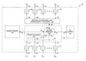
- FIG. 1shows a schematic block diagram of a conventional shared buffer packet switching device at 10 which is commonly employed in networks supporting the propagation of cells (e.g., an ATM network).
- the device 10includes: a plurality of N serial receive ports 12 designated RX 0 , RX 1 , RX 2 , . . . , RX N ⁇ providing serial reception of bits of cells received via associated links (not shown) of a network; and a plurality of N serial transmission ports 14 designated TX 1 , TX 2 , TX 3 , . . . TX N ⁇ providing serial transmission of bits of cells via associated links of the network.
- the serial receive ports RX 0 , RX 1 , RX 2 , . . . , RX N ⁇ and associated ones of the serial transmission ports TX 1 , TX 2 , TX 3 , . . . TX N ⁇are typically formed by bi-directional network ports communicatively coupled with associated network links.
- the shared buffer switching device 10further includes: a source managing unit 18 having a plurality of N ports 20 each for receiving cells from an associated one of the receive ports 12 via an associated one of a plurality of N receive buffers 22 ; a shared buffer 26 having a port 28 communicatively coupled with the source managing unit 18 via a bus 30 as further explained below; and a destination managing unit 34 having a plurality of N ports 36 each being communicatively coupled with an associated one of the transmission ports 14 of the device via an associated one of a plurality of N transmit buffer queues 38 .
- the shared buffer 26is implemented using static random access memory (SRAM) technology, and is addressable by the source managing unit 18 and destination managing unit 34 via memory address values as further explained below.
- SRAMstatic random access memory
- the source managing unit 18includes: a packet forwarding module 50 for receiving cells from each of the receive buffers 22 via a bus 54 , and a port 56 as further explained below; and a buffer managing unit 60 having a port 62 communicatively coupled with each of the receive buffers 22 via the bus 54 , and with port 52 of the packet forwarding module 50 via the bus 54 , a port 64 communicatively coupled with port 28 of the shared buffer 26 via the memory bus 30 , a port 66 communicatively coupled with port 56 of the packet forwarding module, and a port 68 communicatively coupled with port 42 of the destination managing unit 34 . Operation of the device 10 is further explained below.
- FIG. 2shows a generalized table diagram illustrating a memory space at 72 of the shared buffer 26 (FIG. 1 ).
- the memory space 72includes a plurality of word locations 74 of the shared buffer memory space, each word location being addressable via a corresponding memory address value 76 , and having a word storage space 78 for storing an associated word of data having a word length of B bits.
- the shared buffer 26(FIG. 1) is said to have a “width” of B bits, and a “height” equal to the total number of addressable word locations 74 .
- a bandwidth problemarises in using a shared buffer memory for switching variable length packets.
- the packet forwarding module 50is responsive to address values (e.g., MAC address values) carried by the received cells, and operative to determine destination port information associated with each of the received cells by reading a cell forwarding table (not shown), the destination port information indicating a destination one of the transmission ports 14 associated with the received cell.
- the packet forwarding module 50provides the destination port information associated with each one of the received cells to port 66 of the buffer managing unit 60 via its port 56 .
- the buffer managing unit 60is operative to determine a memory address value 76 (FIG. 2) associated with each of the received cells, the associated memory address values indicating word locations 74 (FIG. 2) for storing the received cells.
- the buffer managing unit 60is then operative to store (write) the received cells in the associated word locations 74 (FIG. 2 ), and is also operative to provide the destination information and the memory address values associated with of the each cells to port 42 of the destination managing unit 34 which uses the information to perform output queuing operations.
- the destination managing unit 34receives and temporarily stores the destination information and memory address values associated with each of the cells.
- the destination managing unit 34includes output queuing logic (not shown) for arbitrating between requests on behalf of received cells for access to associated destination ones of the transmit buffer queues 38 . After resolving requests and selecting a received cell for access to an associated one of the transmit buffer queues 38 , the destination managing unit 34 reads the selected cell from the associated word location 74 (FIG. 2) of the shared buffer 26 using the associated memory address value, and forwards the cell to the associated one of the transmit buffer queues 38 .
- the shared buffer 26may serve one of the receive ports 12 or one of the transmission ports 14 at a time for writing (storing) and reading (retrieving) cells.
- the switching device 10is generally synchronous in that cells are received serially by the receive buffers 22 , converted from serial to parallel format, and stored in the shared buffer.
- the buffer manager 60accesses word locations 74 (FIG. 2) of the shared buffer 26 in accordance with allocated times slots associated with each of the receive ports 12 , and with each of the transmission ports 14 .
- the access operationsare synchronized in accordance with a write cycle in which the buffer manager 60 stores a cell received by each of the N receive ports 12 during each of N write time slots, and a read cycle in which the buffer manager 60 reads a cell to be transmitted from each of the N transmission ports 14 during each of N read time slots. Any time slot allocated for a receive port which has not received a cell is wasted during an associated write cycle. Likewise, any time slot allocated for a particular transmission port is wasted during an associated read cycle if no cell is to be transmitted from the particular transmission port.
- RX 0receives a cell determined to be destined for TX 1
- RX 1receives a first cell determined to be destined for TX 2
- RX 2does not receive any cells
- RX 3receives a second cell determined to be destined for TX 2 .
- the buffer manager 60stores the cells received by RX 0 , RX 1 , and RX 3 in associated ones of the word locations 74 (FIG. 2) of the shared buffer.
- the allocated time slot for storing a cell received by RX 2is wasted in this case because RX 2 did not receive any packets.
- the buffer manager 60reads cells stored in associated ones of the word locations 74 (FIG. 2) which are associated with each of the transmission ports 14 .
- the buffer manager 60wastes a first read time slot associated with TX 0 as no packets destined for TX 0 have been received; reads the cell destined for TX 1 , during a second read time slot; reads the first cell destined for TX 2 during the third read time slot; and wastes a fourth read time slot associated with TX 3 as no packets destined for TX 3 have been received.
- the second cell destined for TX 2is left in the shared buffer, and will be retrieved during a subsequent read cycle.
- the switching deviceIn order for a switching device, of any architectural type, to support N ports each having a line rate, R (defined in units of bits per second), the switching device must provide total switching bandwidth performance equal to NR, that is the product of N and R.
- the bandwidth performance of the shared buffer switching device 10is a function of clock rate (which is defined by the time required to access the contents of one word location), and the width, B, of the shared buffer.
- the bandwidth performance of a shared buffer switching devicedetermines the number N of ports which can be served by the device. Therefore, the number of ports which may be supported by the shared buffer device is also a function of the width, B, of the shared buffer.
- the memory bandwidth for accessing the packet buffermust be equal to 2NR, thereby providing a write bandwidth of NR and a read bandwidth of NR.
- the number N of ports, of a uniform line rate, which may be supported by the shared buffer switching device 10may be determined in accordance with Relationship (1), below:
- Clock_Rateis defined in units of cycles per second
- Bis the width of the shared buffer 26 in bits
- Ris the line rate of each of the ports of the switching device.
- the clock rate of the shared buffer switching deviceis 125 MHz which provides for accessing (read or writing) the contents of a word location 74 (FIG. 2) of the shared buffer in 8 nanoseconds.
- the width, B, of the shared buffer 26is 512 bits. This provides a total memory bandwidth of 512 bits per every 8 nanoseconds which is equivalent to 64 Gbits per second.
- the shared buffer 26is implemented using SRAM technology.
- the size of the shared buffer 26may be varied by interconnecting a plurality of commercially available standard size memory units.
- the width, B, of the shared buffer 26may be varied by interconnecting a plurality of memory units in parallel, and, the height of the shared buffer may be varied by interconnecting a plurality of memory units in series.
- One commercially available standard size memory unitis 1K ⁇ 16 bits, that is 1000 words in height and 16 bits wide, and therefore provides for storing one thousand 16-bit words.
- thirty two of the 1K ⁇ 16 bits memory unitsmay be arranged in parallel to form a shared buffer having a width, B, of 512 bits, wherein each word storage unit 78 (FIG. 2) of the packet buffer provides a 512 bit word length.
- bandwidth performancedecreases where a shared buffer memory is used for switching variable length packets.
- Each of the above calculations of bandwidth performancebased on Relationship (1), assumes an ideal case wherein the entire contents of each word storage unit 78 (FIG. 2) of each word location of the shared buffer 26 is utilized for storing a data packet, or a portion of a data packet.
- the overall bandwidth performance of the switching device 10decreases if less than the entire contents of each word storage unit 78 (FIG. 2) of each word location is utilized.
- packet switching devices having a shared buffer architecturehave traditionally been used only in networks wherein the data packets are fixed length data packets.
- the overall bandwidth performance of the switching device 10is maximized where the width of the shared buffer is equal to the fixed length of the cells being switched.
- packet switching devices having a shared buffer architecturehave not been traditionally applied for switching variable length data packets because bandwidth performance suffers in such application. If the length of the packets vary, the bandwidth provided by the switching device 10 is decreased. For example in an Ethernet network, packet lengths vary in a range between 64 bytes and 1522 bytes, each of the packets having an integer number of bytes within the defined range. In a worst case scenario, the bandwidth performance of a packet switching device having a shared buffer architecture is most adversely affected where a received packet has a length which is one byte greater than the width, B, of the packet buffer.
- the bandwidth provided by the switching device 10is maximized at 64 Gbits/s if each of the received packets has a fixed length of 64 bytes.
- Bandwidth performance of the packet switching device 10may be expressed by the product of the width, B, of the shared buffer 26 and the clock rate of the device only if the full memory width is utilized. However, decreased bandwidth performance of the packet switching device, as well as wasted memory space, occurs in response to receiving a packet having a length slightly greater (e.g., one byte greater) than the width of the shared buffer 26 (FIG. 1 ).
- a worst case bandwidth performance of the packet switching deviceoccurs where a received packet has a length equal to 65 bytes. This problem arises because the bandwidth performance of the packet switching device 10 is dependent upon the portion each word location of the shared buffer 26 which is actually utilized.
- the first 64 bytes of the received packetare written to a first one of the word locations 74 (FIG. 2) designated 80 , and a last byte of the received packet is written to a second one of the word locations 74 designated 82 .
- Only a very small portion of the word storage space 78 of the second word location 82is used for storing the last byte of the received packet.
- the remaining portion of the storage space of the second word location 82cannot be used for storing a next packet, or a portion of a next packet, because the output queuing logic of the destination managing unit 34 (FIG.
- each one of the word locations 74 (FIG. 2) of the shared buffermay store data of only one of the received packets so that the memory address value associated with the word location only identifies data of a single stored packet. Because of the wasted storage space of the second word location 82 , the bandwidth performance of the switching device suffers.
- the width of the shared buffer 26may be increased. However, there is a practical limit to how much the width of the shared buffer 26 may be increased, and it is not practical to increase the width of the shared buffer 26 to 1522 bytes in order to accommodate the longest Ethernet packet.
- the worst case bandwidth performance of the packet switching deviceoccurring when a packet having a length of 65 bytes is received, is 32 Gbits/s which is one half of the maximum bandwidth achieved for 64 byte packets. Therefore, only sixteen 1 Gbit ports may be supported by the prior art switching device 10 for switching variable length data packets in the example presented.
- a presently preferred embodiment of the present inventionincludes a shared buffer packet switching device for receiving data packets via associated ones of a plurality of receive ports, and for transmitting data packets via associated selected ones of a plurality of transmit port.
- the shared buffer packet switching deviceincludes: a shared buffer unit for temporarily storing at least a portion of each of a plurality of the data packets received via the receive ports, the shared buffer including a plurality of word locations each being associated with a shared buffer memory address value, and having an associated word storage space, the word storage spaces defining a shared buffer memory width; a tail buffer for temporarily storing remainder portions of selected ones of the received data packets, the tail buffer including a plurality of tail buffer locations each being associated with a tail buffer memory address value, and an associated tail data storage space, the tail data storage spaces defining a tail buffer memory width; and a source managing unit for receiving packets via the input ports, and being operative to store each of the received packets in selected ones of the word locations and the tail buffer locations.
- the source managing unitfurther includes: a packet forwarding module operative to determine destination information associated with each of the received data packets, the destination information indicating an associated destination one of the transmit ports; and a buffer managing unit for determining at least one shared buffer memory address value associated with each of the received packets, and for determining a tail buffer memory address value for selected ones of the received packets.
- a destination managing unitreceives the destination information, the shared buffer memory address values, and tail buffer memory address values, and is operative to access each of the data packets stored in the shared buffer and the tail buffer using the shared buffer memory address values and the tail buffer memory address values.
- the buffer managing unitis operative to perform the steps of: dividing a received packet by the shared buffer memory width to determine a number of the word locations required for storing the received packet, and a remainder number of bits; storing at least a portion of the received packet in at least one associated word location; comparing the remainder number of bits to the tail buffer memory width; determining if the remainder number of bits is less than the tail buffer memory width; if the remainder number of bits is less than the tail buffer memory width, storing the remainder number of bits of the received packet in an associated tail buffer location; and if the remainder number of bits is greater than the tail buffer memory width, storing the remainder number of bits of the received packet in an associated additional word location.
- An important advantage of the shared buffer packet switching device of the present inventionis that bandwidth performance in switching data packets of a variable length is enhanced by use of the tail buffer.
- Bandwidth performance of a shared buffer memory switching deviceis directly proportional to the width of the shared buffer and the percentage of utilized memory space of word locations of the shared buffer.
- Use of the tail bufferallows for less wasted shared buffer memory space for storing packets for which the remainder number of bits is less than the tail buffer memory width.
- FIG. 1is a schematic circuit block diagram of a conventional shared buffer packet switching device
- FIG. 2is a generalized table diagram illustrating a memory space of a shared buffer of the conventional switching device of FIG. 1;
- FIG. 3is a schematic circuit block diagram of a shared buffer packet switching device having a shared buffer and a tail buffer in accordance with the present invention
- FIG. 4Ais a generalized table diagram illustrating a memory space of the shared buffer of FIG. 3;
- FIG. 4Bis a generalized table diagram illustrating a memory space of the tail buffer of FIG. 3.
- FIG. 5is a generalized table diagram illustrating an embodiment of the present invention wherein the height of the shared buffer is greater than the height of the tail buffer.
- FIG. 3shows a schematic circuit block diagram of a shared buffer packet switching device at 100 in accordance with the present invention.
- the device 100includes: a plurality of N serial receive ports 102 designated RX 0 , RX 1 , RX 2 , . . . , RX N ⁇ for serially receiving data packets via associated links of a network (not shown); and a plurality of N serial transmission ports 104 designated TX 1 , TX 2 , TX 3 , . . . TX N ⁇ for transmitting packets via links of a network.
- the serial receive ports RX 0 , RX 1 , RX 2 , . . . . , RX N ⁇ and associated ones of the serial transmission ports 104 TX 1 , TX 2 , TX 3 , . . . TX N ⁇are formed by associated bi-directional ports.
- the shared buffer packet switching device 100further includes: a source managing unit 108 having a plurality of N ports 110 each for receiving packets from an associated one of the serial receive ports 102 via an associated one of a plurality of N receive buffers 112 ; a shared packet buffer 116 having a port 118 communicatively coupled with the source managing unit as further explained below; a tail buffer 120 having a port 122 communicatively coupled with the source managing unit as further explained below; a destination managing unit 124 having a port 126 communicatively coupled with the source managing unit as further explained below; a plurality of N ports 128 each being communicatively coupled with an associated one of the serial transmission ports 104 of the device via an associated one of a plurality of N transmit buffers 130 .
- the shared packet buffer 116 and the tail buffer 120are both implemented using static random access memory (SRAM) technology.
- the source managing unit 108includes: a packet forwarding module 134 having a port 136 for receiving packets from each of the receive buffers 112 via a bus 138 , and a port 137 further explained below; and a buffer managing unit 140 having a port 142 communicatively coupled with each of the receive buffers 112 via the bus 138 and with port 136 of the packet forwarding module 134 via the bus 138 , a port 143 communicatively coupled with port 137 of the packet forwarding module, a port 144 communicatively coupled with port 122 of the tail buffer 120 , a port 146 communicatively coupled with port 118 of the shared packet buffer 116 , and a port 148 communicatively coupled with port 126 of the destination managing unit 124 . Operation of the device 100 is further explained below.
- FIG. 4Ashows a generalized table diagram illustrating a memory space at 170 of the shared buffer 116 (FIG. 3 ).
- the memory space 170includes a plurality of word locations 172 of the shared buffer memory space, each word location being addressable via a corresponding shared buffer memory address value 174 , each word location having an associated word storage space 176 for storing an associated word of data having a word length of B s bits.
- the shared buffer 116(FIG. 3) is said to have a “width” of B s bits, and a “height” equal to the total number of addressable word locations 172 .
- FIG. 4Bshows a generalized table diagram illustrating a memory space at 180 of the tail buffer 120 (FIG. 3 ).
- the memory space 180includes a plurality of tail buffer locations 182 each being addressable via a corresponding tail buffer memory address value 184 , and having a tail data storage space 186 for storing an associated portion of data having a maximum length of B T bits.
- the tail buffer 120(FIG. 3) is said to have a “width” of B T bits, and a “height” equal to the total number of addressable locations 182 in the tail buffer.
- packetsare received serially via associated network links (not shown) at each one of the receive ports 102 and temporarily stored in the receive buffers 112 which are used in converting the received packets from the serial data format to a parallel data format.
- the packet forwarding module 134is responsive to address values (e.g., MAC address values) carried by the received packets, and is operative to determine destination port information associated with each of the received packets by reading a packet forwarding table (not shown), the destination port information indicating a destination one of the transmission ports 104 associated with the received packet.
- the packet forwarding module 134provides the destination port information associated with each one of the received packets to port 143 of the buffer managing unit 140 via its port 137 .
- the buffer managing unit 140is operative to determine selected ones of the word locations 172 (FIG. 4 A), as well as selected ones of the tail buffer locations 182 if appropriate, for storing the received packets.
- the buffer managing unit 140is operative to perform the steps of: dividing a received packet by the width B s of the shared buffer 116 , and determining a remainder number of bits; comparing the remainder number of bits to the width B T of the tail buffer; determining if the remainder number of bits is less than the width B T of the tail buffer; if the remainder number of bits is less than the width B T of the tail buffer, using one of the tail buffer locations 182 (FIG.
- the buffer managing unit 140is operative to determine: at least one shared buffer memory address value 172 (FIG. 4A) associated with each of the received packets; and an associated tail buffer memory address value 184 (FIG. 4B) if appropriate as explained above.
- the associated shared buffer memory address valuesindicate word locations 172 (FIG. 2) for storing at least portions of received packets, and the tail buffer memory address values indicate associated tail buffer locations 182 (FIG. 4B) for storing remainder portions of received packets.
- the buffer managing unit 140is operative to store (write) an associated portion of the received packets in the associated word locations 172 (FIG. 4 A), and also in the associated tail buffer location when appropriate.
- the buffer managing unit 140is also operative to provide the destination information and the memory address values associated with of the each packets to port 126 of the destination managing unit 124 .
- the destination managing unit 124receives and temporarily stores the destination information and memory address values associated with each of the packets.
- the destination managing unit 124includes output queuing logic (not shown) for arbitrating between requests on behalf of received packets for access to corresponding ones of the transmit buffer queues 130 .
- the destination managing unit 124reads at least a portion of the selected packet from the associated word location 172 (FIG. 4A) of the shared buffer using the associated shared buffer memory address value(s) 174 , and also reads an associated portion of the selected packet from the associated tail buffer location 182 (FIG. 4B) of the tail buffer using an associated tail buffer memory address value(s) 184 if applicable.
- the destination managing unit 124forwards the packet to the associated one of the transmit buffer queues 130 .
- An important advantage of the shared buffer packet switching device of the present inventionis that bandwidth performance in switching data packets of a variable length is enhanced by use of the tail buffer.
- Bandwidth performance of a shared buffer memory switching deviceis directly proportional to the width of the shared buffer and the percentage of utilized memory space of word locations of the shared buffer.
- Use of the tail bufferallows for less waste of shared buffer memory space for storing packets for which the remainder number of bits is less than the tail buffer memory width B T .
- Portions of word locations 172 (FIG. 4A) of the shared bufferare only wasted for cases wherein the remainder number of bits for a packet (after dividing the length of the packet by the shared buffer memory width B s ) is greater than the tail buffer memory width B T .
- the memory width B T of the tail buffer, and the memory width B s of the shared buffermay be may be varied in order to optimize bandwidth performance and utilization of memory space.
- the shared buffer 116(FIG. 3) includes a number of word locations 172 (FIG. 4A) equal to the number of tail buffer locations 182 (FIG. 4B) in the tail buffer 120 (FIG. 3 ), and therefore the height of the shared buffer is equal to the height of the tail buffer.
- An unnecessary disadvantagesarise in this embodiment if the range of variation of the length packets is large because several of the word locations 172 (FIG. 4A) may be required store a single large packet, while a maximum of only one of the tail buffer locations 182 (FIG. 4B) is required to store a remaining portion of the packet.
- Much of the memory space of the tail bufferis wasted in this embodiment because of the one to one relation ships between word locations 172 (FIG. 4A) and tail buffer locations 182 (FIG. 4 B).
- output queuing operations performed by the destination managing unitare performed on a word level wherein portions of the shared buffer memory space 170 (FIG. 4A) are assigned to associated packets one word location 172 (FIG. 4A) at a time.
- two portions of a data packetmay be stored in nonconsecutive ones of the word locations because different ones of the receive ports 102 (FIG. 3) write to the shared buffer 116 (FIG. 3) at different times.
- three portions of a received data packetmay be stored in three separate nonconsecutive word locations designated 190 , 192 , and 194 .
- the buffer managing unit 140(FIG. 3) must determine a plurality of associated shared buffer memory address values 174 (FIG. 4A) for each packet having a length greater than or equal to twice the width of the shared buffer, in addition to a tail buffer memory address value 184 (FIG. 4B) if required.
- the destination managing unit 124must be provided with a plurality of associated shared buffer memory address values, and a tail buffer memory address value if required, for each received data packet which has a length greater than twice the width of the shared buffer. Generating and using more than one shared buffer memory address value for storing and accessing packets in the shared buffer is somewhat cumbersome because additional registers are required for storing the memory address values. In summary, word level queuing may not be ideal for some switching applications because a large tail buffer is required, and because additional registers are required for storing more than one memory address value for accessing each packet.
- FIG. 5shows a generalized table diagram illustrating an embodiment of the present invention at 200 wherein the height of the shared buffer 116 (FIG. 3) is greater than the height of the tail buffer 120 (FIG. 3 ).
- at least one memory space unit 202 of the buffer memory spaceis assigned by the buffer managing unit 140 (FIG. 3) for storing each received data packet.
- the buffer managing unit 140(FIG. 3) for storing each received data packet.
- the output queuing schemeis referred to as a block level queuing scheme because only one tail buffer location 182 is required for each memory space unit 202 which includes a block of the word locations 172 .
- the width of the shared buffer 116(FIG. 3) is 64 bytes, and each of the memory space units 202 includes eight of the word locations 172 thereby providing 512 bytes of storage space.
- the total shared buffer memory spaceis 16K words ⁇ 64 Bytes providing for 1 Megabyte of shared buffer storage space
- the total tail buffer memory spaceis 2K words ⁇ 16 Bytes providing for 32 Kilobytes of tail buffer storage space.
- tail buffer 5allows for use of a tail buffer having a smaller height, less tail buffer locations, than the word level queuing embodiment because in this block level queuing scheme, only one tail buffer location 182 is required for each memory space unit 202 , as opposed to the word level queuing scheme wherein one tail buffer location is required for each word location.
Landscapes
- Engineering & Computer Science (AREA)
- Computer Networks & Wireless Communication (AREA)
- Signal Processing (AREA)
- Data Exchanges In Wide-Area Networks (AREA)
Abstract
Description
Claims (13)
Priority Applications (7)
| Application Number | Priority Date | Filing Date | Title |
|---|---|---|---|
| US09/526,102US6700894B1 (en) | 2000-03-15 | 2000-03-15 | Method and apparatus for shared buffer packet switching |
| AU2001245284AAU2001245284A1 (en) | 2000-03-15 | 2001-03-09 | Method and apparatus for shared buffer packet switching |
| AT01918178TATE371315T1 (en) | 2000-03-15 | 2001-03-09 | METHOD AND DEVICE FOR PACKET SWITCHING USING A SHARED BUFFER MEMORY |
| PCT/US2001/004954WO2001069849A2 (en) | 2000-03-15 | 2001-03-09 | Method and apparatus for shared buffer packet switching |
| DE60130079TDE60130079T2 (en) | 2000-03-15 | 2001-03-09 | METHOD AND DEVICE FOR PACKET TRANSMISSION BY MEANS OF A PARTICULAR BUFFER STORAGE |
| EP01918178AEP1192753B1 (en) | 2000-03-15 | 2001-03-09 | Method and apparatus for shared buffer packet switching |
| US10/703,523US7315550B2 (en) | 2000-03-15 | 2003-11-10 | Method and apparatus for shared buffer packet switching |
Applications Claiming Priority (1)
| Application Number | Priority Date | Filing Date | Title |
|---|---|---|---|
| US09/526,102US6700894B1 (en) | 2000-03-15 | 2000-03-15 | Method and apparatus for shared buffer packet switching |
Related Child Applications (1)
| Application Number | Title | Priority Date | Filing Date |
|---|---|---|---|
| US10/703,523ContinuationUS7315550B2 (en) | 2000-03-15 | 2003-11-10 | Method and apparatus for shared buffer packet switching |
Publications (1)
| Publication Number | Publication Date |
|---|---|
| US6700894B1true US6700894B1 (en) | 2004-03-02 |
Family
ID=24095914
Family Applications (2)
| Application Number | Title | Priority Date | Filing Date |
|---|---|---|---|
| US09/526,102Expired - Fee RelatedUS6700894B1 (en) | 2000-03-15 | 2000-03-15 | Method and apparatus for shared buffer packet switching |
| US10/703,523Active2026-03-13US7315550B2 (en) | 2000-03-15 | 2003-11-10 | Method and apparatus for shared buffer packet switching |
Family Applications After (1)
| Application Number | Title | Priority Date | Filing Date |
|---|---|---|---|
| US10/703,523Active2026-03-13US7315550B2 (en) | 2000-03-15 | 2003-11-10 | Method and apparatus for shared buffer packet switching |
Country Status (6)
| Country | Link |
|---|---|
| US (2) | US6700894B1 (en) |
| EP (1) | EP1192753B1 (en) |
| AT (1) | ATE371315T1 (en) |
| AU (1) | AU2001245284A1 (en) |
| DE (1) | DE60130079T2 (en) |
| WO (1) | WO2001069849A2 (en) |
Cited By (36)
| Publication number | Priority date | Publication date | Assignee | Title |
|---|---|---|---|---|
| US20020018469A1 (en)* | 2000-07-17 | 2002-02-14 | Roke Manor Research Limited | Switching devices |
| US20020091884A1 (en)* | 2000-11-17 | 2002-07-11 | Andrew Chang | Method and system for translating data formats |
| US20020089977A1 (en)* | 2000-11-17 | 2002-07-11 | Andrew Chang | Network switch cross point |
| US20020097713A1 (en)* | 2000-11-17 | 2002-07-25 | Andrew Chang | Backplane interface adapter |
| US20020105966A1 (en)* | 2000-11-17 | 2002-08-08 | Ronak Patel | Backplane interface adapter with error control and redundant fabric |
| US20040076147A1 (en)* | 2001-03-16 | 2004-04-22 | Alain Loge | Variable sized information frame switch for on-board security networks |
| US20040090976A1 (en)* | 2000-03-15 | 2004-05-13 | Broadcom Corporation | Method and apparatus for shared buffer packet switching |
| US20040109463A1 (en)* | 2002-12-05 | 2004-06-10 | Alcatel Canada Inc. | Efficient data transmission method |
| US20040179548A1 (en)* | 2000-11-17 | 2004-09-16 | Andrew Chang | Method and system for encoding wide striped cells |
| US20050089049A1 (en)* | 2001-05-15 | 2005-04-28 | Foundry Networks, Inc. | High-performance network switch |
| US6917623B1 (en)* | 2001-03-26 | 2005-07-12 | Advanced Micro Devices, Inc. | System and method for transferring data in a network device |
| US20050175018A1 (en)* | 2003-05-15 | 2005-08-11 | Wong Yuen F. | System and method for high speed packet transmission implementing dual transmit and receive pipelines |
| US20060062233A1 (en)* | 2000-12-19 | 2006-03-23 | Chiaro Networks Ltd. | System and method for router queue and congestion management |
| US7187687B1 (en) | 2002-05-06 | 2007-03-06 | Foundry Networks, Inc. | Pipeline method and system for switching packets |
| US7266117B1 (en) | 2002-05-06 | 2007-09-04 | Foundry Networks, Inc. | System architecture for very fast ethernet blade |
| US20070288690A1 (en)* | 2006-06-13 | 2007-12-13 | Foundry Networks, Inc. | High bandwidth, high capacity look-up table implementation in dynamic random access memory |
| US20080002707A1 (en)* | 2002-05-06 | 2008-01-03 | Davis Ian E | Flexible method for processing data packets in a network routing system for enhanced efficiency and monitoring capability |
| US20080028157A1 (en)* | 2003-01-13 | 2008-01-31 | Steinmetz Joseph H | Global shared memory switch |
| US20080049742A1 (en)* | 2006-08-22 | 2008-02-28 | Deepak Bansal | System and method for ecmp load sharing |
| US20080225859A1 (en)* | 1999-01-12 | 2008-09-18 | Mcdata Corporation | Method for scoring queued frames for selective transmission through a switch |
| US20090100500A1 (en)* | 2007-10-15 | 2009-04-16 | Foundry Networks, Inc. | Scalable distributed web-based authentication |
| US20090279549A1 (en)* | 2005-12-28 | 2009-11-12 | Foundry Networks, Inc. | Hitless software upgrades |
| US20090279542A1 (en)* | 2007-01-11 | 2009-11-12 | Foundry Networks, Inc. | Techniques for using dual memory structures for processing failure detection protocol packets |
| US20090279558A1 (en)* | 2002-05-06 | 2009-11-12 | Ian Edward Davis | Network routing apparatus for enhanced efficiency and monitoring capability |
| US20090282322A1 (en)* | 2007-07-18 | 2009-11-12 | Foundry Networks, Inc. | Techniques for segmented crc design in high speed networks |
| US20090279559A1 (en)* | 2004-03-26 | 2009-11-12 | Foundry Networks, Inc., A Delaware Corporation | Method and apparatus for aggregating input data streams |
| US7649885B1 (en) | 2002-05-06 | 2010-01-19 | Foundry Networks, Inc. | Network routing system for enhanced efficiency and monitoring capability |
| US7657703B1 (en) | 2004-10-29 | 2010-02-02 | Foundry Networks, Inc. | Double density content addressable memory (CAM) lookup scheme |
| US8090901B2 (en) | 2009-05-14 | 2012-01-03 | Brocade Communications Systems, Inc. | TCAM management approach that minimize movements |
| US8149839B1 (en) | 2007-09-26 | 2012-04-03 | Foundry Networks, Llc | Selection of trunk ports and paths using rotation |
| US8238255B2 (en) | 2006-11-22 | 2012-08-07 | Foundry Networks, Llc | Recovering from failures without impact on data traffic in a shared bus architecture |
| US8271859B2 (en) | 2007-07-18 | 2012-09-18 | Foundry Networks Llc | Segmented CRC design in high speed networks |
| US8599850B2 (en) | 2009-09-21 | 2013-12-03 | Brocade Communications Systems, Inc. | Provisioning single or multistage networks using ethernet service instances (ESIs) |
| US8671219B2 (en) | 2002-05-06 | 2014-03-11 | Foundry Networks, Llc | Method and apparatus for efficiently processing data packets in a computer network |
| US8730961B1 (en) | 2004-04-26 | 2014-05-20 | Foundry Networks, Llc | System and method for optimizing router lookup |
| US10250495B2 (en)* | 2005-05-06 | 2019-04-02 | Orckit Ip, Llc | Tunnel provisioning with link aggregation |
Families Citing this family (6)
| Publication number | Priority date | Publication date | Assignee | Title |
|---|---|---|---|---|
| FR2838899B1 (en)* | 2002-04-19 | 2004-08-27 | Cit Alcatel | ROUTING DEVICE WITH PARALLEL PROCESSING |
| US7489362B2 (en)* | 2003-03-04 | 2009-02-10 | Broadcom Corporation | Television functionality on a chip |
| US7561597B2 (en)* | 2003-08-14 | 2009-07-14 | Broadcom Corporation | System and method for data packet substitution |
| US8386750B2 (en)* | 2008-10-31 | 2013-02-26 | Cray Inc. | Multiprocessor system having processors with different address widths and method for operating the same |
| US9846658B2 (en)* | 2014-04-21 | 2017-12-19 | Cisco Technology, Inc. | Dynamic temporary use of packet memory as resource memory |
| US11789858B2 (en)* | 2020-08-11 | 2023-10-17 | Samsung Electronics Co., Ltd. | Method and system for performing read/write operation within a computing system hosting non-volatile memory |
Citations (11)
| Publication number | Priority date | Publication date | Assignee | Title |
|---|---|---|---|---|
| US5499263A (en)* | 1993-02-22 | 1996-03-12 | Alcatel N.V. | Multiplexing arrangement |
| US5541912A (en)* | 1994-10-04 | 1996-07-30 | At&T Corp. | Dynamic queue length thresholds in a shared memory ATM switch |
| US5745491A (en)* | 1995-08-31 | 1998-04-28 | Victor Company Of Japan, Ltd. | Information storage and output system |
| US5838677A (en)* | 1995-04-18 | 1998-11-17 | Hitachi, Ltd. | Switching system having means for congestion control by monitoring packets in a shared buffer and by suppressing the reading of packets from input buffers |
| US5905725A (en) | 1996-12-16 | 1999-05-18 | Juniper Networks | High speed switching device |
| US5910928A (en) | 1993-08-19 | 1999-06-08 | Mmc Networks, Inc. | Memory interface unit, shared memory switch system and associated method |
| US6044061A (en)* | 1998-03-10 | 2000-03-28 | Cabletron Systems, Inc. | Method and apparatus for fair and efficient scheduling of variable-size data packets in an input-buffered multipoint switch |
| US6061358A (en)* | 1997-02-13 | 2000-05-09 | Mcdata Corporation | Data communication system utilizing a scalable, non-blocking, high bandwidth central memory controller and method |
| US6094435A (en)* | 1997-06-30 | 2000-07-25 | Sun Microsystems, Inc. | System and method for a quality of service in a multi-layer network element |
| US6272143B1 (en)* | 1998-03-20 | 2001-08-07 | Accton Technology Corporation | Quasi-pushout method associated with upper-layer packet discarding control for packet communication systems with shared buffer memory |
| US6377546B1 (en)* | 1998-05-12 | 2002-04-23 | International Business Machines Corporation | Rate guarantees through buffer management |
Family Cites Families (2)
| Publication number | Priority date | Publication date | Assignee | Title |
|---|---|---|---|---|
| US5901928A (en)* | 1996-06-14 | 1999-05-11 | Aptek, Inc. | Active turbulence control technique for drag reduction |
| US6700894B1 (en)* | 2000-03-15 | 2004-03-02 | Broadcom Corporation | Method and apparatus for shared buffer packet switching |
- 2000
- 2000-03-15USUS09/526,102patent/US6700894B1/ennot_activeExpired - Fee Related
- 2001
- 2001-03-09WOPCT/US2001/004954patent/WO2001069849A2/enactiveIP Right Grant
- 2001-03-09ATAT01918178Tpatent/ATE371315T1/ennot_activeIP Right Cessation
- 2001-03-09AUAU2001245284Apatent/AU2001245284A1/ennot_activeAbandoned
- 2001-03-09EPEP01918178Apatent/EP1192753B1/ennot_activeExpired - Lifetime
- 2001-03-09DEDE60130079Tpatent/DE60130079T2/ennot_activeExpired - Lifetime
- 2003
- 2003-11-10USUS10/703,523patent/US7315550B2/enactiveActive
Patent Citations (11)
| Publication number | Priority date | Publication date | Assignee | Title |
|---|---|---|---|---|
| US5499263A (en)* | 1993-02-22 | 1996-03-12 | Alcatel N.V. | Multiplexing arrangement |
| US5910928A (en) | 1993-08-19 | 1999-06-08 | Mmc Networks, Inc. | Memory interface unit, shared memory switch system and associated method |
| US5541912A (en)* | 1994-10-04 | 1996-07-30 | At&T Corp. | Dynamic queue length thresholds in a shared memory ATM switch |
| US5838677A (en)* | 1995-04-18 | 1998-11-17 | Hitachi, Ltd. | Switching system having means for congestion control by monitoring packets in a shared buffer and by suppressing the reading of packets from input buffers |
| US5745491A (en)* | 1995-08-31 | 1998-04-28 | Victor Company Of Japan, Ltd. | Information storage and output system |
| US5905725A (en) | 1996-12-16 | 1999-05-18 | Juniper Networks | High speed switching device |
| US6061358A (en)* | 1997-02-13 | 2000-05-09 | Mcdata Corporation | Data communication system utilizing a scalable, non-blocking, high bandwidth central memory controller and method |
| US6094435A (en)* | 1997-06-30 | 2000-07-25 | Sun Microsystems, Inc. | System and method for a quality of service in a multi-layer network element |
| US6044061A (en)* | 1998-03-10 | 2000-03-28 | Cabletron Systems, Inc. | Method and apparatus for fair and efficient scheduling of variable-size data packets in an input-buffered multipoint switch |
| US6272143B1 (en)* | 1998-03-20 | 2001-08-07 | Accton Technology Corporation | Quasi-pushout method associated with upper-layer packet discarding control for packet communication systems with shared buffer memory |
| US6377546B1 (en)* | 1998-05-12 | 2002-04-23 | International Business Machines Corporation | Rate guarantees through buffer management |
Cited By (99)
| Publication number | Priority date | Publication date | Assignee | Title |
|---|---|---|---|---|
| US20100135312A1 (en)* | 1999-01-12 | 2010-06-03 | Mitchem W Jeffrey | Method for Scoring Queued Frames for Selective Transmission Through a Switch |
| US7848253B2 (en) | 1999-01-12 | 2010-12-07 | Mcdata Corporation | Method for scoring queued frames for selective transmission through a switch |
| US20080225859A1 (en)* | 1999-01-12 | 2008-09-18 | Mcdata Corporation | Method for scoring queued frames for selective transmission through a switch |
| US8014315B2 (en) | 1999-01-12 | 2011-09-06 | Mcdata Corporation | Method for scoring queued frames for selective transmission through a switch |
| US7315550B2 (en)* | 2000-03-15 | 2008-01-01 | Broadcom Corporation | Method and apparatus for shared buffer packet switching |
| US20040090976A1 (en)* | 2000-03-15 | 2004-05-13 | Broadcom Corporation | Method and apparatus for shared buffer packet switching |
| US20020018469A1 (en)* | 2000-07-17 | 2002-02-14 | Roke Manor Research Limited | Switching devices |
| US6956859B2 (en)* | 2000-07-27 | 2005-10-18 | Roke Manor Research Limited | Switching devices |
| US7512127B2 (en) | 2000-11-17 | 2009-03-31 | Foundry Networks, Inc. | Backplane interface adapter |
| US7995580B2 (en) | 2000-11-17 | 2011-08-09 | Foundry Networks, Inc. | Backplane interface adapter with error control and redundant fabric |
| US20090287952A1 (en)* | 2000-11-17 | 2009-11-19 | Foundry Networks, Inc. | Backplane Interface Adapter with Error Control and Redundant Fabric |
| US8964754B2 (en) | 2000-11-17 | 2015-02-24 | Foundry Networks, Llc | Backplane interface adapter with error control and redundant fabric |
| US20040179548A1 (en)* | 2000-11-17 | 2004-09-16 | Andrew Chang | Method and system for encoding wide striped cells |
| US20090290499A1 (en)* | 2000-11-17 | 2009-11-26 | Foundry Networks, Inc. | Backplane Interface Adapter with Error Control and Redundant Fabric |
| US8619781B2 (en) | 2000-11-17 | 2013-12-31 | Foundry Networks, Llc | Backplane interface adapter with error control and redundant fabric |
| US7203194B2 (en) | 2000-11-17 | 2007-04-10 | Foundry Networks, Inc. | Method and system for encoding wide striped cells |
| US20100034215A1 (en)* | 2000-11-17 | 2010-02-11 | Foundry Networks, Inc. | Backplane Interface Adapter with Error Control |
| US7236490B2 (en) | 2000-11-17 | 2007-06-26 | Foundry Networks, Inc. | Backplane interface adapter |
| US8514716B2 (en) | 2000-11-17 | 2013-08-20 | Foundry Networks, Llc | Backplane interface adapter with error control and redundant fabric |
| US9030937B2 (en) | 2000-11-17 | 2015-05-12 | Foundry Networks, Llc | Backplane interface adapter with error control and redundant fabric |
| US20020091884A1 (en)* | 2000-11-17 | 2002-07-11 | Andrew Chang | Method and system for translating data formats |
| US20020089977A1 (en)* | 2000-11-17 | 2002-07-11 | Andrew Chang | Network switch cross point |
| US7978702B2 (en) | 2000-11-17 | 2011-07-12 | Foundry Networks, Llc | Backplane interface adapter |
| US7948872B2 (en) | 2000-11-17 | 2011-05-24 | Foundry Networks, Llc | Backplane interface adapter with error control and redundant fabric |
| US7356030B2 (en) | 2000-11-17 | 2008-04-08 | Foundry Networks, Inc. | Network switch cross point |
| US20020105966A1 (en)* | 2000-11-17 | 2002-08-08 | Ronak Patel | Backplane interface adapter with error control and redundant fabric |
| US20020097713A1 (en)* | 2000-11-17 | 2002-07-25 | Andrew Chang | Backplane interface adapter |
| US20090279561A1 (en)* | 2000-11-17 | 2009-11-12 | Foundry Networks, Inc. | Backplane Interface Adapter |
| US7596139B2 (en) | 2000-11-17 | 2009-09-29 | Foundry Networks, Inc. | Backplane interface adapter with error control and redundant fabric |
| US7813365B2 (en) | 2000-12-19 | 2010-10-12 | Foundry Networks, Inc. | System and method for router queue and congestion management |
| US20060062233A1 (en)* | 2000-12-19 | 2006-03-23 | Chiaro Networks Ltd. | System and method for router queue and congestion management |
| US7522611B2 (en)* | 2001-03-16 | 2009-04-21 | Thales | Variable sized information frame switch for on-board security networks |
| US20040076147A1 (en)* | 2001-03-16 | 2004-04-22 | Alain Loge | Variable sized information frame switch for on-board security networks |
| US6917623B1 (en)* | 2001-03-26 | 2005-07-12 | Advanced Micro Devices, Inc. | System and method for transferring data in a network device |
| US20050089049A1 (en)* | 2001-05-15 | 2005-04-28 | Foundry Networks, Inc. | High-performance network switch |
| US7206283B2 (en) | 2001-05-15 | 2007-04-17 | Foundry Networks, Inc. | High-performance network switch |
| US7738450B1 (en) | 2002-05-06 | 2010-06-15 | Foundry Networks, Inc. | System architecture for very fast ethernet blade |
| US8194666B2 (en) | 2002-05-06 | 2012-06-05 | Foundry Networks, Llc | Flexible method for processing data packets in a network routing system for enhanced efficiency and monitoring capability |
| US8989202B2 (en) | 2002-05-06 | 2015-03-24 | Foundry Networks, Llc | Pipeline method and system for switching packets |
| US8671219B2 (en) | 2002-05-06 | 2014-03-11 | Foundry Networks, Llc | Method and apparatus for efficiently processing data packets in a computer network |
| US7187687B1 (en) | 2002-05-06 | 2007-03-06 | Foundry Networks, Inc. | Pipeline method and system for switching packets |
| US7266117B1 (en) | 2002-05-06 | 2007-09-04 | Foundry Networks, Inc. | System architecture for very fast ethernet blade |
| US7649885B1 (en) | 2002-05-06 | 2010-01-19 | Foundry Networks, Inc. | Network routing system for enhanced efficiency and monitoring capability |
| US20090279548A1 (en)* | 2002-05-06 | 2009-11-12 | Foundry Networks, Inc. | Pipeline method and system for switching packets |
| US20090279558A1 (en)* | 2002-05-06 | 2009-11-12 | Ian Edward Davis | Network routing apparatus for enhanced efficiency and monitoring capability |
| US8170044B2 (en) | 2002-05-06 | 2012-05-01 | Foundry Networks, Llc | Pipeline method and system for switching packets |
| US20080002707A1 (en)* | 2002-05-06 | 2008-01-03 | Davis Ian E | Flexible method for processing data packets in a network routing system for enhanced efficiency and monitoring capability |
| US7468975B1 (en) | 2002-05-06 | 2008-12-23 | Foundry Networks, Inc. | Flexible method for processing data packets in a network routing system for enhanced efficiency and monitoring capability |
| US7830884B2 (en) | 2002-05-06 | 2010-11-09 | Foundry Networks, Llc | Flexible method for processing data packets in a network routing system for enhanced efficiency and monitoring capability |
| US7813367B2 (en) | 2002-05-06 | 2010-10-12 | Foundry Networks, Inc. | Pipeline method and system for switching packets |
| US20040109463A1 (en)* | 2002-12-05 | 2004-06-10 | Alcatel Canada Inc. | Efficient data transmission method |
| US20160021031A1 (en)* | 2003-01-13 | 2016-01-21 | Avago Technologies General Ip (Singapore) Pte. Ltd. | Global shared memory switch |
| US20080028157A1 (en)* | 2003-01-13 | 2008-01-31 | Steinmetz Joseph H | Global shared memory switch |
| US8718051B2 (en) | 2003-05-15 | 2014-05-06 | Foundry Networks, Llc | System and method for high speed packet transmission |
| US8811390B2 (en) | 2003-05-15 | 2014-08-19 | Foundry Networks, Llc | System and method for high speed packet transmission |
| US20100046521A1 (en)* | 2003-05-15 | 2010-02-25 | Foundry Networks, Inc. | System and Method for High Speed Packet Transmission |
| US20050175018A1 (en)* | 2003-05-15 | 2005-08-11 | Wong Yuen F. | System and method for high speed packet transmission implementing dual transmit and receive pipelines |
| US7636369B2 (en) | 2003-05-15 | 2009-12-22 | Foundry Networks, Inc. | System and method for high speed packet transmission implementing dual transmit and receive pipelines |
| US9461940B2 (en) | 2003-05-15 | 2016-10-04 | Foundry Networks, Llc | System and method for high speed packet transmission |
| US20090279559A1 (en)* | 2004-03-26 | 2009-11-12 | Foundry Networks, Inc., A Delaware Corporation | Method and apparatus for aggregating input data streams |
| US9338100B2 (en) | 2004-03-26 | 2016-05-10 | Foundry Networks, Llc | Method and apparatus for aggregating input data streams |
| US8493988B2 (en) | 2004-03-26 | 2013-07-23 | Foundry Networks, Llc | Method and apparatus for aggregating input data streams |
| US7817659B2 (en) | 2004-03-26 | 2010-10-19 | Foundry Networks, Llc | Method and apparatus for aggregating input data streams |
| US8730961B1 (en) | 2004-04-26 | 2014-05-20 | Foundry Networks, Llc | System and method for optimizing router lookup |
| US7657703B1 (en) | 2004-10-29 | 2010-02-02 | Foundry Networks, Inc. | Double density content addressable memory (CAM) lookup scheme |
| US7953923B2 (en) | 2004-10-29 | 2011-05-31 | Foundry Networks, Llc | Double density content addressable memory (CAM) lookup scheme |
| US7953922B2 (en) | 2004-10-29 | 2011-05-31 | Foundry Networks, Llc | Double density content addressable memory (CAM) lookup scheme |
| US20100100671A1 (en)* | 2004-10-29 | 2010-04-22 | Foundry Networks, Inc. | Double density content addressable memory (cam) lookup scheme |
| US11838205B2 (en) | 2005-05-06 | 2023-12-05 | Corrigent Corporation | Tunnel provisioning with link aggregation |
| US10911350B2 (en) | 2005-05-06 | 2021-02-02 | Orckit Ip, Llc | Tunnel provisioning with link aggregation |
| US10250495B2 (en)* | 2005-05-06 | 2019-04-02 | Orckit Ip, Llc | Tunnel provisioning with link aggregation |
| US11418437B2 (en) | 2005-05-06 | 2022-08-16 | Orckit Ip, Llc | Tunnel provisioning with link aggregation |
| US10523561B2 (en) | 2005-05-06 | 2019-12-31 | Orckit Ip, Llc | Tunnel provisioning with link aggregation |
| US9378005B2 (en) | 2005-12-28 | 2016-06-28 | Foundry Networks, Llc | Hitless software upgrades |
| US8448162B2 (en) | 2005-12-28 | 2013-05-21 | Foundry Networks, Llc | Hitless software upgrades |
| US20090279549A1 (en)* | 2005-12-28 | 2009-11-12 | Foundry Networks, Inc. | Hitless software upgrades |
| US20070288690A1 (en)* | 2006-06-13 | 2007-12-13 | Foundry Networks, Inc. | High bandwidth, high capacity look-up table implementation in dynamic random access memory |
| US20080049742A1 (en)* | 2006-08-22 | 2008-02-28 | Deepak Bansal | System and method for ecmp load sharing |
| US7903654B2 (en) | 2006-08-22 | 2011-03-08 | Foundry Networks, Llc | System and method for ECMP load sharing |
| US9030943B2 (en) | 2006-11-22 | 2015-05-12 | Foundry Networks, Llc | Recovering from failures without impact on data traffic in a shared bus architecture |
| US8238255B2 (en) | 2006-11-22 | 2012-08-07 | Foundry Networks, Llc | Recovering from failures without impact on data traffic in a shared bus architecture |
| US7978614B2 (en) | 2007-01-11 | 2011-07-12 | Foundry Network, LLC | Techniques for detecting non-receipt of fault detection protocol packets |
| US9112780B2 (en) | 2007-01-11 | 2015-08-18 | Foundry Networks, Llc | Techniques for processing incoming failure detection protocol packets |
| US8155011B2 (en) | 2007-01-11 | 2012-04-10 | Foundry Networks, Llc | Techniques for using dual memory structures for processing failure detection protocol packets |
| US20090279542A1 (en)* | 2007-01-11 | 2009-11-12 | Foundry Networks, Inc. | Techniques for using dual memory structures for processing failure detection protocol packets |
| US20090279441A1 (en)* | 2007-01-11 | 2009-11-12 | Foundry Networks, Inc. | Techniques for transmitting failure detection protocol packets |
| US8395996B2 (en) | 2007-01-11 | 2013-03-12 | Foundry Networks, Llc | Techniques for processing incoming failure detection protocol packets |
| US8037399B2 (en) | 2007-07-18 | 2011-10-11 | Foundry Networks, Llc | Techniques for segmented CRC design in high speed networks |
| US20090282322A1 (en)* | 2007-07-18 | 2009-11-12 | Foundry Networks, Inc. | Techniques for segmented crc design in high speed networks |
| US8271859B2 (en) | 2007-07-18 | 2012-09-18 | Foundry Networks Llc | Segmented CRC design in high speed networks |
| US8509236B2 (en) | 2007-09-26 | 2013-08-13 | Foundry Networks, Llc | Techniques for selecting paths and/or trunk ports for forwarding traffic flows |
| US8149839B1 (en) | 2007-09-26 | 2012-04-03 | Foundry Networks, Llc | Selection of trunk ports and paths using rotation |
| US8799645B2 (en) | 2007-10-15 | 2014-08-05 | Foundry Networks, LLC. | Scalable distributed web-based authentication |
| US8667268B2 (en) | 2007-10-15 | 2014-03-04 | Foundry Networks, Llc | Scalable distributed web-based authentication |
| US8190881B2 (en) | 2007-10-15 | 2012-05-29 | Foundry Networks Llc | Scalable distributed web-based authentication |
| US20090100500A1 (en)* | 2007-10-15 | 2009-04-16 | Foundry Networks, Inc. | Scalable distributed web-based authentication |
| US8090901B2 (en) | 2009-05-14 | 2012-01-03 | Brocade Communications Systems, Inc. | TCAM management approach that minimize movements |
| US9166818B2 (en) | 2009-09-21 | 2015-10-20 | Brocade Communications Systems, Inc. | Provisioning single or multistage networks using ethernet service instances (ESIs) |
| US8599850B2 (en) | 2009-09-21 | 2013-12-03 | Brocade Communications Systems, Inc. | Provisioning single or multistage networks using ethernet service instances (ESIs) |
Also Published As
| Publication number | Publication date |
|---|---|
| AU2001245284A1 (en) | 2001-09-24 |
| WO2001069849A3 (en) | 2002-01-10 |
| WO2001069849A2 (en) | 2001-09-20 |
| ATE371315T1 (en) | 2007-09-15 |
| US7315550B2 (en) | 2008-01-01 |
| DE60130079D1 (en) | 2007-10-04 |
| US20040090976A1 (en) | 2004-05-13 |
| DE60130079T2 (en) | 2008-05-15 |
| EP1192753B1 (en) | 2007-08-22 |
| EP1192753A2 (en) | 2002-04-03 |
Similar Documents
| Publication | Publication Date | Title |
|---|---|---|
| US6700894B1 (en) | Method and apparatus for shared buffer packet switching | |
| US7391721B1 (en) | Maintaining counters and updating a secondary counter storage | |
| AU642830B2 (en) | Multiple virtual fifo arrangement | |
| JP4046943B2 (en) | Multiport internal cache DRAM | |
| US4849968A (en) | Buffer management system | |
| US8161205B1 (en) | Packet buffer management apparatus and method | |
| US5687173A (en) | Addressable high speed counter array | |
| EP1508225B1 (en) | Method for data storage in external and on-chip memory in a packet switch | |
| US6957309B1 (en) | Method and apparatus for re-accessing a FIFO location | |
| US20050081003A1 (en) | Apparatus and method for efficient data storage in a digital logic device | |
| US20100054272A1 (en) | Storage device capable of accommodating high-speed network using large-capacity low-speed memory | |
| US6314489B1 (en) | Methods and systems for storing cell data using a bank of cell buffers | |
| US7161950B2 (en) | Systematic memory location selection in Ethernet switches | |
| JP3103298B2 (en) | ATM switch address generation circuit | |
| US6885591B2 (en) | Packet buffer circuit and method | |
| US7116659B2 (en) | Data transmission memory | |
| US6831920B1 (en) | Memory vacancy management apparatus and line interface unit | |
| AU624745B2 (en) | Packet/fast packet switch for voice and data | |
| US7143185B1 (en) | Method and apparatus for accessing external memories | |
| KR100243414B1 (en) | Queuing apparatus and method of virtual connection unit | |
| KR100198789B1 (en) | Receiving connecting network interface structure | |
| JP2006135379A (en) | Packet processing apparatus and packet processing method | |
| JPH03268539A (en) | Vci conversion system in atm speech path |
Legal Events
| Date | Code | Title | Description |
|---|---|---|---|
| AS | Assignment | Owner name:ALLAYER COMMUNICATIONS, CALIFORNIA Free format text:ASSIGNMENT OF ASSIGNORS INTEREST;ASSIGNOR:SHUNG, CHUEN-SHEN BERNARD;REEL/FRAME:010929/0922 Effective date:20000630 | |
| AS | Assignment | Owner name:BROADCOM CORPORATION, CALIFORNIA Free format text:ASSIGNMENT OF ASSIGNORS INTEREST;ASSIGNOR:ALLAYER COMMUNICATIONS;REEL/FRAME:011663/0283 Effective date:20010320 | |
| FEPP | Fee payment procedure | Free format text:PAYOR NUMBER ASSIGNED (ORIGINAL EVENT CODE: ASPN); ENTITY STATUS OF PATENT OWNER: LARGE ENTITY | |
| FEPP | Fee payment procedure | Free format text:PAT HOLDER NO LONGER CLAIMS SMALL ENTITY STATUS, ENTITY STATUS SET TO UNDISCOUNTED (ORIGINAL EVENT CODE: STOL); ENTITY STATUS OF PATENT OWNER: LARGE ENTITY | |
| FPAY | Fee payment | Year of fee payment:4 | |
| FPAY | Fee payment | Year of fee payment:8 | |
| REMI | Maintenance fee reminder mailed | ||
| AS | Assignment | Owner name:BANK OF AMERICA, N.A., AS COLLATERAL AGENT, NORTH CAROLINA Free format text:PATENT SECURITY AGREEMENT;ASSIGNOR:BROADCOM CORPORATION;REEL/FRAME:037806/0001 Effective date:20160201 Owner name:BANK OF AMERICA, N.A., AS COLLATERAL AGENT, NORTH Free format text:PATENT SECURITY AGREEMENT;ASSIGNOR:BROADCOM CORPORATION;REEL/FRAME:037806/0001 Effective date:20160201 | |
| LAPS | Lapse for failure to pay maintenance fees | ||
| STCH | Information on status: patent discontinuation | Free format text:PATENT EXPIRED DUE TO NONPAYMENT OF MAINTENANCE FEES UNDER 37 CFR 1.362 | |
| FP | Lapsed due to failure to pay maintenance fee | Effective date:20160302 | |
| AS | Assignment | Owner name:AVAGO TECHNOLOGIES GENERAL IP (SINGAPORE) PTE. LTD., SINGAPORE Free format text:ASSIGNMENT OF ASSIGNORS INTEREST;ASSIGNOR:BROADCOM CORPORATION;REEL/FRAME:041706/0001 Effective date:20170120 Owner name:AVAGO TECHNOLOGIES GENERAL IP (SINGAPORE) PTE. LTD Free format text:ASSIGNMENT OF ASSIGNORS INTEREST;ASSIGNOR:BROADCOM CORPORATION;REEL/FRAME:041706/0001 Effective date:20170120 | |
| AS | Assignment | Owner name:BROADCOM CORPORATION, CALIFORNIA Free format text:TERMINATION AND RELEASE OF SECURITY INTEREST IN PATENTS;ASSIGNOR:BANK OF AMERICA, N.A., AS COLLATERAL AGENT;REEL/FRAME:041712/0001 Effective date:20170119 | |
| AS | Assignment | Owner name:AVAGO TECHNOLOGIES INTERNATIONAL SALES PTE. LIMITE Free format text:MERGER;ASSIGNOR:AVAGO TECHNOLOGIES GENERAL IP (SINGAPORE) PTE. LTD.;REEL/FRAME:047195/0026 Effective date:20180509 | |
| AS | Assignment | Owner name:AVAGO TECHNOLOGIES INTERNATIONAL SALES PTE. LIMITE Free format text:CORRECTIVE ASSIGNMENT TO CORRECT THE EFFECTIVE DATE OF MERGER PREVIOUSLY RECORDED ON REEL 047195 FRAME 0026. ASSIGNOR(S) HEREBY CONFIRMS THE MERGER;ASSIGNOR:AVAGO TECHNOLOGIES GENERAL IP (SINGAPORE) PTE. LTD.;REEL/FRAME:047477/0423 Effective date:20180905 |