US6700669B1 - Method and system for three-dimensional imaging using light pattern having multiple sub-patterns - Google Patents
Method and system for three-dimensional imaging using light pattern having multiple sub-patternsDownload PDFInfo
- Publication number
- US6700669B1 US6700669B1US09/771,531US77153101AUS6700669B1US 6700669 B1US6700669 B1US 6700669B1US 77153101 AUS77153101 AUS 77153101AUS 6700669 B1US6700669 B1US 6700669B1
- Authority
- US
- United States
- Prior art keywords
- light
- sub
- scene
- patterns
- light pattern
- Prior art date
- Legal status (The legal status is an assumption and is not a legal conclusion. Google has not performed a legal analysis and makes no representation as to the accuracy of the status listed.)
- Expired - Fee Related, expires
Links
- 238000003384imaging methodMethods0.000titleclaimsabstractdescription26
- 238000000034methodMethods0.000titleclaimsdescription30
- 238000001228spectrumMethods0.000claimsabstractdescription36
- 230000003287optical effectEffects0.000claimsabstractdescription13
- 238000004364calculation methodMethods0.000claimsdescription10
- 230000007246mechanismEffects0.000claimsdescription10
- 230000003044adaptive effectEffects0.000claimsdescription8
- 239000000463materialSubstances0.000claimsdescription5
- 238000004040coloringMethods0.000claims1
- 238000005286illuminationMethods0.000description12
- 238000005259measurementMethods0.000description8
- 238000010586diagramMethods0.000description7
- 239000002131composite materialSubstances0.000description6
- 230000000694effectsEffects0.000description5
- 230000014509gene expressionEffects0.000description5
- 238000004422calculation algorithmMethods0.000description4
- 230000003595spectral effectEffects0.000description4
- 230000010363phase shiftEffects0.000description3
- 230000008569processEffects0.000description3
- 230000005684electric fieldEffects0.000description2
- 238000001914filtrationMethods0.000description2
- 230000035945sensitivityEffects0.000description2
- 238000009825accumulationMethods0.000description1
- 230000004913activationEffects0.000description1
- 238000004458analytical methodMethods0.000description1
- 230000008901benefitEffects0.000description1
- 239000003086colorantSubstances0.000description1
- 238000006073displacement reactionMethods0.000description1
- 239000011521glassSubstances0.000description1
- 238000012804iterative processMethods0.000description1
- 239000005304optical glassSubstances0.000description1
- 238000010206sensitivity analysisMethods0.000description1
- 230000003068static effectEffects0.000description1
- 238000004441surface measurementMethods0.000description1
- 239000012780transparent materialSubstances0.000description1
- 238000001429visible spectrumMethods0.000description1
Images


Classifications
- G—PHYSICS
- G01—MEASURING; TESTING
- G01S—RADIO DIRECTION-FINDING; RADIO NAVIGATION; DETERMINING DISTANCE OR VELOCITY BY USE OF RADIO WAVES; LOCATING OR PRESENCE-DETECTING BY USE OF THE REFLECTION OR RERADIATION OF RADIO WAVES; ANALOGOUS ARRANGEMENTS USING OTHER WAVES
- G01S17/00—Systems using the reflection or reradiation of electromagnetic waves other than radio waves, e.g. lidar systems
- G01S17/88—Lidar systems specially adapted for specific applications
- G01S17/89—Lidar systems specially adapted for specific applications for mapping or imaging
- G—PHYSICS
- G01—MEASURING; TESTING
- G01B—MEASURING LENGTH, THICKNESS OR SIMILAR LINEAR DIMENSIONS; MEASURING ANGLES; MEASURING AREAS; MEASURING IRREGULARITIES OF SURFACES OR CONTOURS
- G01B11/00—Measuring arrangements characterised by the use of optical techniques
- G01B11/24—Measuring arrangements characterised by the use of optical techniques for measuring contours or curvatures
- G01B11/25—Measuring arrangements characterised by the use of optical techniques for measuring contours or curvatures by projecting a pattern, e.g. one or more lines, moiré fringes on the object
- G01B11/2513—Measuring arrangements characterised by the use of optical techniques for measuring contours or curvatures by projecting a pattern, e.g. one or more lines, moiré fringes on the object with several lines being projected in more than one direction, e.g. grids, patterns
Definitions
- the present inventionis directed to three-dimensional surface profile imaging, and more particularly to a method and apparatus for three-dimensional imaging that uses color ranging to conduct surface profile measurement.
- a three dimensional surface profile imaging method and apparatus described in U.S. Pat. No. 5,675,407(“the '407 patent”), the disclosure of which is incorporated herein by reference in its entirety, conducts imaging by projecting light through an optical filter, such as linear variable wavelength filter (LVWF), thereby projecting light having a known, spatially distributed wavelength spectrum on the objects being imaged.
- the LVWFis a rectangular optical glass plate coated with a color-filtering film that gradually varies in color, (i.e., wavelength). If the color spectrum of a LVWF is within the visible light region, one edge of the filter rectangle may correspond to the shortest visible wavelength (i.e. blue or violet) while the opposite edge may correspond to the longest visible wavelength, (i.e. red).
- the wavelength of light passing through the coated color-filtering layeris linearly proportional to the distance between the position on the filter glass where the light passes and the blue or red edge. Consequently, the color of the light is directly related to the angle ⁇ , shown in FIG. 1, at which the light leaves the rainbow projector and LVWF.
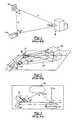
- the imaging method and apparatusis based on the triangulation principle and the relationship between a light projector 100 having the LVWF, a camera 102 , and the object being imaged 104 .
- a triangleis uniquely defined by the angles theta ( ⁇ ) and alpha ( ⁇ ), and the length of the baseline (B).
- the distancei.e., the range R
- the key to the triangulation methodis to determine the projection angle, ⁇ , from an image captured by the camera 102 and more particularly to determine all ⁇ angles corresponding to all the visible points on an object's surface in order to obtain a full-frame 3D image in one snapshot.
- FIG. 2is a more detailed version of FIG. 1 and illustrates the manner in which all visible points on the object's surface 104 is obtained via the triangulation method.
- the light projector 100generates a fan beam of light 200 .
- the fan beam 200is broad spectrum light (i.e., white light) which passes through the LVWF to illuminate one or more three-dimensional objects 104 in the scene with a pattern of light rays possessing a rainbow-like spectrum distribution.
- the fan beam of light 200is composed of multiple vertical planes of light, or “light sheets”, each plane having a given projection angle and wavelength.
- the light reflected from the surface of the object 104is then detected by the camera 102 .
- a visible spectrum range LVWF400-700 nm
- the color detected by the camera pixelsis determined by the proportion of its primary color Red, Green, and Blue components (RGB).
- RGBRed, Green, and Blue components
- the color spectrum of each pixelhas a one-tone correspondence with the projection angle ( ⁇ ) of the plane of light due to the fixed geometry of the camera 102 lens and the LVWF characteristics. Therefore, the color of light received by the camera 102 can be used to determine the angle ⁇ at which that light left the rainbow light projector.
- Other spectrum rangescan also be used in similar fashion. The implementation is straightforward to those skilled in the art.
- the angle ais determined by the physical relationship between the camera 102 and the coordinates of each pixel on the camera's imaging plane.
- the baseline B between the camera's 102 focal point and the center of the cylindrical lens of the light projector 100is fixed and known. Given the value for angles ⁇ and ⁇ , together with the known baseline length B, all necessary information is provided to easily determine the full frame of three-dimensional range values (x,y,z) for any and every visible spot on the surface of the objects seen by the camera 102 .
- the three dimensional imaging system described abovecan capture full-frame, high spatial resolution three-dimensional images using a standard camera, such as a charge coupled device camera, in real time without relying on any moving parts.
- a standard camerasuch as a charge coupled device camera
- the imaging systemdoes not rely on a laser, it does not pose any hazard to the eyes when used in clinical applications.
- the wavelength of the light projected onto the object surfacecontinuously varies, there is no theoretical limitation on the measurement accuracy that can be achieved by the system. The actual accuracy of a specific system will depend on system implementation and will be affected primarily by limiting factors such as the optical system design, the quality and resolution of the camera, light spectral emission of the light source projector; noise level and resolution of the frame grabber, calibration algorithms, and the three-dimensional imaging processing algorithms.
- the systemmay obtain an image of the object under normal light conditions before projecting the filtered light onto the object.
- the image obtained under normal light conditionsis then subtracted from the image obtained under LVWF light conditions to eliminate the effects of the ambient light on the image.
- (x p , y p )is the location of the rainbow light projector
- (x c , y c )is the location of imaging sensor
- Bis the baseline between the rainbow projector and the imaging sensor (CCD)
- ⁇⁇
- Ois a surface point on the object in the scene
- Ris the three-dimensional range, that is, the distance between (x c , y c ) and O.
- ⁇ R[ cos ⁇ ⁇ ⁇ sin ⁇ ⁇ ⁇ ⁇ b ] ⁇ z p ( x - x p ) 2 + z p 2 ⁇ ⁇ ⁇ x ( 6 )
- the continuously varying wavelength pattern obtained via the light projector 100 and the LVWF 101is projected spatially onto surfaces of a three-dimensional object or scene 104 .
- a ( ⁇ , ⁇ ) lookup tablecan be established for the color matching operation.
- An image sensor device(such as the CCD camera 102 ) that collects the reflection from object's surfaces also provides wavelength information for each pixel in an image, enabling the determination of the projection angle ⁇ corresponding to each image pixel through the color matching operation based on the ( ⁇ , ⁇ ) lookup table.
- the accuracy of the color match operationaffects the accuracy of the three-dimensional surface measurement.
- Equation (8)Using Equ. (8) in Equ. (9), the expression becomes:
- the imaging systemprojects a light pattern that could be described as a “single rainbow projection” pattern because the pattern ranges over the visible light spectrum a single time.
- This type of patternhas a variation rate that depends on numerous factors, including the field of view of the camera/image sensor, the distance between the light projector and the object being imaged, as well as other factors. As a result, it is difficult to adjust the spectral variation rate of the single rainbow projection pattern to fit the accuracy requirements of many three-dimensional imaging tasks.
- the present inventionis directed to a system and method that generates a light pattern that contains multiple cycles of light spectra or sub-patterns.
- the light patternincludes two or more cycles of spectra of visible or infrared light, arranged contiguously with each other.
- the light patternmay also be generated by sequentially emitting two or more sub-patterns.
- the multiple spectra light patternis generated by projecting the light from the light source through a planar member, such as a slotted panel, that is movable to generate small phase shifts in the light pattern.
- a planar membersuch as a slotted panel
- the multiple patterns and/or sub-patterns used to illuminate the object being imagedimproves resolution and measurement accuracy by reducing color mismatch error.
- FIG. 1is a simplified diagram illustrating a triangulation principle used in the present invention
- FIG. 2is a representative diagram of the components used by the inventive system.
- FIG. 3is a plan view of the system shown in FIG. 2;
- FIG. 4is a representative diagram illustrating the effect of errors in range calculation
- FIGS. 5 a and 5 bare graphs comparing the slopes of the illumination pattern on measurement accuracy
- FIGS. 6 a and 6 bare light pattern spatial displacement graphs corresponding to one embodiment of the present invention.
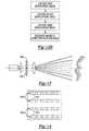
- FIGS. 7 a , 7 b and 7 cillustrate a multiple spectra light projection pattern according to the present invention
- FIG. 8is a representative diagram of the manner in which a point search is conducted for the multiple spectra light projection pattern
- FIG. 9is a flowchart of an adaptive initial point calculation method used in the present invention.
- FIGS. 10 a and 10 bare diagrams illustrating the effect of sensor characteristics on light pattern distortion
- FIG. 11illustrates another embodiment of the inventive system
- FIGS. 12 a and 12 billustrate a light pattern and method that is generated from a composite image of multiple sub-patterns according to another embodiment of the invention
- FIG. 13is a representative diagram of another embodiment of the invention using a slotted plate
- FIG. 14illustrates examples of cross-sections of the slotted plate used in FIG. 13;
- FIG. 15is an illustrative diagram showing the manner in which the slot plane generates a spatially varying light intensity pattern.
- FIGS. 16 a and 16 billustrate alternative systems incorporating the slotted plate.
- FIGS. 6 a and 6 billustrate one manner in which the light projection pattern can be modified to improve resolution and measurement accuracy.
- FIGS. 6 a and 6 bassume that the light pattern is a single rainbow projection pattern.
- the light patterncontains red, green and blue (RGB) components.
- the intensities of the RGB components in the light patternare modulated so that the intensity of each R, G, B component varies between high and low points, i.e. from a peak to a valley, and forms multiple cycles of pattern variation.
- the locations of the peak-valley points for the R, G, and B sub-patternsare spread over the spatial period of the light pattern, as shown in FIG. 6 b . Notice that the distribution of R, G, and B does not need to be evenly spaced across the spatial period.
- this embodimentuses a single rainbow projection pattern as the light pattern, the one-to-one correspondence between the wavelength of a light sheet in the light pattern and its projection angle still applies in this embodiment.
- the light pattern from the light projectordoes not have to be limited to a single spectrum, where a one-to-one correspondence between a given wavelength and a given projection angle applies.
- the light patternmay include multiple cycles of spectra, such as multiple visible light spectra, such that a given wavelength from the light projector could be generated and transmitted in several projection directions, i.e. at several projection angles. This will be referred to as a “multiple rainbow projection” pattern, even though the spectra is not limited to the visible rainbow light spectrum.
- the look-up tablewill contain two or more projection angles for each wavelength (a one-to-many relationship).
- the multiple rainbow projection systemrequires an additional procedure to select the correct projection angle for a given wavelength.
- FIGS. 8 and 9is a graph and flowchart, respectively, outlining the procedure for conducting color matching for a one-to-many lookup table that contains multiple projection angles for a given wavelength. To avoid any mismatching from an incorrect projection angle selection, the method shown in FIG. 9 can be used to reduce any ambiguities.
- adaptive controlcan be used to determine the initial condition in the search. More particularly, an adaptive initial point calculation mechanism may be used to ensure that the initial point at which the iterative search method begins is at least somewhat close to the correct result, particularly because the final result of iterative processes tends to depend on the selected initial condition.
- an adaptive initial point calculation mechanismmay be used to ensure that the initial point at which the iterative search method begins is at least somewhat close to the correct result, particularly because the final result of iterative processes tends to depend on the selected initial condition.
- the initial point of the searchis determined by a correct match point in the search of a neighboring pixel.
- the underlying assumption hereis that most portions of the surface of a physical object being imaged are continuous.
- the projected, i.e., reflected, coloris similar for neighboring portions of the object, and therefore the initial projection angle value should also be very similar.
- the processstarts by determining origin point coordinates (x 0 , y 0 , z 0 ) at step 900 .
- This pointcan be, for example, the upper right-hand pixel in the image.
- the inventive systemuses color matching to obtain projection angle candidates at step 904 . For example, if the object is being illuminated with two identical rainbow spectra are arranged horizontally, i.e., right and left, with respect to each other, it can be assumed that the light resulting in the upper right-hand pixel of the image taken results from light in the right-hand spectrum as reflected by the object.
- the wavelength of that lightis matched to the angle at which that wavelength is being emitted in the right-hand, as opposed to the left-hand, rainbow spectrum.
- the value for (x′ i , y′ i , z′ i ) obtained at step 906is compared with previously obtained neighborhood point (x i ⁇ 1 , y i ⁇ 1 , z i ⁇ 1 ) to determine the correct value for (x i , y i , z i ) at step 908 . If the iteration process is determined to be complete at step 910 , then the process ends. Otherwise, another iteration is conducted to refine the determination of the value of (x i , y i , z i ).
- the look-up table for a multiple rainbow projection systemhas multiple projection angles associated with any given wavelength when the light pattern is viewed as a whole, the system restricts the search space in the color matching operation within a smaller range (e.g., within one sub-pattern) so that, as a practical matter, there is a one-to-one correspondence between the wavelength and the projection angle when the search is restricted to within the sub-pattern.
- the actual projection pattern appearing on the image received by the camerais the convolution of the projection pattern produced by the light source and the sensitivity characteristics of the image sensor. As shown in the FIG. 10 a , if an image sensor has a nonlinear sensitivity, a linear projection pattern provided by the light source may be distorted into a nonlinear variation pattern in the received image.
- the pre-calibrate the characteristics of the image sensor 102it may be desirable to pre-calibrate the characteristics of the image sensor 102 , then apply its inverse function to the desired projection pattern design, resulting in a pre-distorted projection pattern, as shown in FIG. 10 b .
- the pre-distortion projection patterncompensates for any non-linearities in the camera or image sensor so that the final pattern on the image captured by the image sensor is ideal and distortion-free.
- the light projectormarked ⁇ circle around ( 1 ) ⁇
- the multiple rainbow projection patternsmarked ⁇ circle around ( 2 ) ⁇
- the reflected lightis detected by a pair of color CCD cameras, marked ⁇ circle around ( 3 ) ⁇ and ⁇ circle around ( 4 ) ⁇ .
- the imageswhich contain both intensity and color components, will be grabbed by a real time frame grabber board, marked ⁇ circle around ( 5 ) ⁇ , into a host computer, marked ⁇ circle around ( 6 ) ⁇ , to perform pixel-to-pixel color matching and triangulation calculation, based on the similarity of color patterns and intensity variation in the neighborhood of pixels in stereo image pairs.
- the color spectrum of pixels on the captured imagesis determined by the proportion of Red, Green and Blue components (RGB) associated with the individual pixel.
- RGBRed, Green and Blue components
- pixel-to-pixel registrationcan be easily performed based on matching the color components of counterparts.
- the locations of a pair of corresponding pixels in a stereo image pairprovide sufficient information to determine viewing angles ⁇ 1 and ⁇ 2 .
- a full frame of a three-dimensional imagecan be obtained from a single snap shot, and a stream of three-dimensional images can be generated at the camera's frame rate (e.g., 30 frames per second or higher).
- the stereo matching and triangulation methods used in this embodimentreduces the dependence of distinguishing features, such as edges and corners, on an object's surface in conducting the measurement.
- a multiple rainbow projection patterncan be represented as a combination of three individual bands of color, namely red, green, and blue (or other colors, if a different color space is defined).
- Each band of color componentsR, G, B
- R, G, Bcan be projected sequentially so that a monochromic camera can collect the reflected images for each color component upon each projection.
- These imagesare then combined to form a composite “color” image, which is equivalent to the color image produced by a color camera under the multiple rainbow projection, as illustrated in FIG. 12 a .
- FIG. 12 boutlines the method corresponding to the sequential images illustrated in FIG. 12 a .
- the resulting composite imagecan be used like any color image and can be captured by systems employing one camera or multiple cameras.
- this embodimentis most suitable for acquiring images of static or slowly moving objects.
- the above examplesassumed that an optical filter is used to produce the illumination pattern, such as a rainbow pattern, on the object or scene being imaged.
- the light from the light sourceis projected through the optical filter to generate the light pattern.
- the quality of the light patterndepends greatly on the quality of the optical filter, which can be expensive and difficult to produce.
- FIGS. 13 through 16 a and 16 billustrate an alternative structure that can create multiple-periods of a light pattern having gradually changing intensities.
- a planar member 1000 with slots 1002 cut through the member to form a slotted plate 1000may be used.
- the slotted plate 1000can be made of any non-transparent material and have any physical dimensions and any thickness.
- the width of each slot 1002is made to be the same as the width of the material between the slots.
- the cross-sectional shape of the slotsthemselves can have any desired shape and do not need to conform to any specific dimensions.
- the slotted plate 1002can be placed in a similar position as the optical filter, in front of the light source so that the light from the source is projected toward the object being imaged through the slotted plate.
- a light projector using the slotted plate 1000is able to generate the desired spatially-varying illumination pattern on objects in a scene with varying light intensity crossing the scene.
- Intensity⁇ s ⁇ I ⁇ ( s , l ) ⁇ ⁇ ⁇ s
- sis the location of the point light sources element
- lis the location on the surface of object
- I(s, l)is the illumination intensity on the surface of object at the l location produced by point light source of s.
- Accumulation of the light illumination from all of the point light sourcesforms the desired spatially varying illumination intensity on the object's surface at locations that are away from the focal plane of the light projection system, as illustrated in FIG. 15 . Shifting the position of the slotted plate 1002 relative to the object surface creates small phase shifts of the illumination intensity pattern to allow triangulation of each point on the object being imaged.
- FIGS. 16 a and 16 billustrate two possible structures for shifting the slot plate position to provide phase shifts in the illumination intensity pattern.
- FIG. 16 ashows one possible microshifting mechanism using a piece of bimorpher material 1004 to support the slotted plate 1002 .
- Bimorpher materialshave the unique property of electrical field induced motion. By fixing one end of the bimorpher support 1004 , the other end of the bimorpher support 1004 can be controlled to move transversally by applying DC voltage on the two sides of the bimorpher support 1004 .
- the bimorpher support 1004can be fixed, for example, on the light source and the slot plate, supported by the bimorpher support 1004 , can be controlled to move the slot plate 1002 relative to the position of the light source 100 by applying different electrical fields to the bimorpher support member 1004 . Consequently, the zigzag illumination pattern can be shifted. In many application of three-dimensional imaging, the micro-shifting of the slot plate 1002 position can generate sufficient shift of the zigzag waveform to allow for triangulation of each point on the object being imaged 104 .
- FIG. 16 bAn alternative embodiment, as shown in FIG. 16 b , of the micro-shift mechanism uses a pair of miniature electromagnetic actuators 1004 and a flexible bar 1005 supporting the slotted plate 1004 . More particularly, activation of the actuators 1004 can move the flexible bar 1005 , and thereby the slot plate 1002 , in transverse directions.
- the slotted plate 1002can be used with, for example, a camera and a single-color light source.
- the monochromatic camerapreferably illuminates the object three times with the slotted plate 1002 in a different position each time.
- These three imagesare then processed by the system's computer as if they represented the red, green and blue components of a color image.
- the resulting composite imagewhile not actually in color, contains variation that can be arbitrarily associated with color.
- This pseudo-color imageis then used by the system to determine the angle at which light left the light source to illuminate each point or pixel on the object being imaged.
- This methodis proceeds in precisely the manner outlined above when, for example, an LVWF is used to provide a rainbow or wavelength varying light pattern on the object being imaged.
- three-dimensional rangingcan be performed according to any ranging technique such as, for example, the technique described in U.S. Pat. No. 5,675,407, the disclosure of which is incorporated herein by reference.
Landscapes
- Physics & Mathematics (AREA)
- Engineering & Computer Science (AREA)
- General Physics & Mathematics (AREA)
- Computer Networks & Wireless Communication (AREA)
- Electromagnetism (AREA)
- Radar, Positioning & Navigation (AREA)
- Remote Sensing (AREA)
- Computer Vision & Pattern Recognition (AREA)
- Length Measuring Devices By Optical Means (AREA)
Abstract
Description


Claims (43)
Priority Applications (2)
| Application Number | Priority Date | Filing Date | Title |
|---|---|---|---|
| US09/771,531US6700669B1 (en) | 2000-01-28 | 2001-01-29 | Method and system for three-dimensional imaging using light pattern having multiple sub-patterns |
| US10/426,083US6937348B2 (en) | 2000-01-28 | 2003-04-28 | Method and apparatus for generating structural pattern illumination |
Applications Claiming Priority (2)
| Application Number | Priority Date | Filing Date | Title |
|---|---|---|---|
| US17869500P | 2000-01-28 | 2000-01-28 | |
| US09/771,531US6700669B1 (en) | 2000-01-28 | 2001-01-29 | Method and system for three-dimensional imaging using light pattern having multiple sub-patterns |
Related Child Applications (1)
| Application Number | Title | Priority Date | Filing Date |
|---|---|---|---|
| US10/426,083Continuation-In-PartUS6937348B2 (en) | 2000-01-28 | 2003-04-28 | Method and apparatus for generating structural pattern illumination |
Publications (1)
| Publication Number | Publication Date |
|---|---|
| US6700669B1true US6700669B1 (en) | 2004-03-02 |
Family
ID=31720137
Family Applications (1)
| Application Number | Title | Priority Date | Filing Date |
|---|---|---|---|
| US09/771,531Expired - Fee RelatedUS6700669B1 (en) | 2000-01-28 | 2001-01-29 | Method and system for three-dimensional imaging using light pattern having multiple sub-patterns |
Country Status (1)
| Country | Link |
|---|---|
| US (1) | US6700669B1 (en) |
Cited By (59)
| Publication number | Priority date | Publication date | Assignee | Title |
|---|---|---|---|---|
| US20020041282A1 (en)* | 2000-08-08 | 2002-04-11 | Ricoh Company, Ltd. | Shape measurement system |
| US20020196415A1 (en)* | 2001-06-26 | 2002-12-26 | Olympus Optical Co., Ltd. | Three-dimensional information acquisition apparatus, projection pattern in three-dimensional information acquisition, and three-dimensional information acquisition method |
| US20030223083A1 (en)* | 2000-01-28 | 2003-12-04 | Geng Z Jason | Method and apparatus for generating structural pattern illumination |
| US20040192377A1 (en)* | 1999-07-30 | 2004-09-30 | Curitell Communications Inc. | Method and apparatus for interfacing among mobile terminal, base station and core network in mobile telecommunications system |
| US20050011470A1 (en)* | 2002-11-08 | 2005-01-20 | Dataflow/Alaska, Inc. | System for uniquely identifying subjects from a target population |
| US20050024606A1 (en)* | 2003-07-29 | 2005-02-03 | Baoxin Li | Projection system |
| US6873924B1 (en)* | 2003-09-30 | 2005-03-29 | General Electric Company | Method and system for calibrating relative fields of view of multiple cameras |
| US20050088529A1 (en)* | 2003-10-23 | 2005-04-28 | Geng Z. J. | System and a method for three-dimensional imaging systems |
| US20050128197A1 (en)* | 2003-12-11 | 2005-06-16 | Strider Labs, Inc. | Probable reconstruction of surfaces in occluded regions by computed symmetry |
| US20050168705A1 (en)* | 2004-02-02 | 2005-08-04 | Baoxin Li | Projection system |
| US20050200857A1 (en)* | 2004-03-15 | 2005-09-15 | Northrop Grumman Corporation | Color coded light for automated shape measurement using photogrammetry |
| US20050243330A1 (en)* | 2004-04-28 | 2005-11-03 | Simon Magarill | Methods and apparatus for determining three dimensional configurations |
| US20050244078A1 (en)* | 2004-04-28 | 2005-11-03 | Simon Magarill | Photographic slides having specified transmission functions |
| US20060244977A1 (en)* | 2005-04-21 | 2006-11-02 | Mladen Gomercic | Projector for an arrangement for three-dimensional optical measurement of objects |
| US7144115B2 (en) | 2004-04-14 | 2006-12-05 | Sharp Laboratories Of America, Inc. | Projection system |
| US20080063239A1 (en)* | 2006-09-13 | 2008-03-13 | Ford Motor Company | Object detection system and method |
| CN100387065C (en)* | 2003-07-07 | 2008-05-07 | 财团法人工业技术研究院 | Three-dimensional color information extraction method and device |
| US20080117438A1 (en)* | 2006-11-16 | 2008-05-22 | Solvision Inc. | System and method for object inspection using relief determination |
| US7411688B1 (en) | 2006-03-17 | 2008-08-12 | Arius3D Inc. | Method and system for laser intensity calibration in a three-dimensional multi-color laser scanning system |
| US7440590B1 (en)* | 2002-05-21 | 2008-10-21 | University Of Kentucky Research Foundation | System and technique for retrieving depth information about a surface by projecting a composite image of modulated light patterns |
| WO2009016367A1 (en) | 2007-07-31 | 2009-02-05 | Third Dimension Software Limited | Optical triangulation sensor |
| US20090140926A1 (en)* | 2007-12-04 | 2009-06-04 | Elden Douglas Traster | System and method for localization utilizing dynamically deployable beacons |
| US20090169095A1 (en)* | 2008-01-02 | 2009-07-02 | Spatial Integrated Systems, Inc. | System and method for generating structured light for 3-dimensional image rendering |
| US20090189858A1 (en)* | 2008-01-30 | 2009-07-30 | Jeff Lev | Gesture Identification Using A Structured Light Pattern |
| US20100007717A1 (en)* | 2008-07-09 | 2010-01-14 | Prime Sense Ltd | Integrated processor for 3d mapping |
| EP2159538A1 (en) | 2008-08-28 | 2010-03-03 | Omnitron AG | Method and device for calculating the location and/or shape of an object |
| US20100110165A1 (en)* | 2007-03-23 | 2010-05-06 | Keigo Iizuka | Divergence ratio distance mapping camera |
| US20100118123A1 (en)* | 2007-04-02 | 2010-05-13 | Prime Sense Ltd | Depth mapping using projected patterns |
| US20100201811A1 (en)* | 2009-02-12 | 2010-08-12 | Prime Sense Ltd. | Depth ranging with moire patterns |
| US20100225746A1 (en)* | 2009-03-05 | 2010-09-09 | Prime Sense Ltd | Reference image techniques for three-dimensional sensing |
| US20100265316A1 (en)* | 2009-04-16 | 2010-10-21 | Primesense Ltd. | Three-dimensional mapping and imaging |
| US20100290698A1 (en)* | 2007-06-19 | 2010-11-18 | Prime Sense Ltd | Distance-Varying Illumination and Imaging Techniques for Depth Mapping |
| US20110025827A1 (en)* | 2009-07-30 | 2011-02-03 | Primesense Ltd. | Depth Mapping Based on Pattern Matching and Stereoscopic Information |
| US20110102320A1 (en)* | 2007-12-05 | 2011-05-05 | Rudolf Hauke | Interaction arrangement for interaction between a screen and a pointer object |
| US20110134114A1 (en)* | 2009-12-06 | 2011-06-09 | Primesense Ltd. | Depth-based gain control |
| US20110211044A1 (en)* | 2010-03-01 | 2011-09-01 | Primesense Ltd. | Non-Uniform Spatial Resource Allocation for Depth Mapping |
| US20120236317A1 (en)* | 2011-03-16 | 2012-09-20 | Canon Kabushiki Kaisha | Three-dimensional distance measurement apparatus, three-dimensional distance measurement method, and non-transitory computer-readable storage medium |
| US8462357B2 (en) | 2009-11-04 | 2013-06-11 | Technologies Numetrix Inc. | Device and method for obtaining three-dimensional object surface data |
| EP2728306A1 (en)* | 2012-11-05 | 2014-05-07 | Hexagon Technology Center GmbH | Method and device for determining three-dimensional coordinates of an object |
| US9030528B2 (en) | 2011-04-04 | 2015-05-12 | Apple Inc. | Multi-zone imaging sensor and lens array |
| US9063283B2 (en) | 2005-10-11 | 2015-06-23 | Apple Inc. | Pattern generation using a diffraction pattern that is a spatial fourier transform of a random pattern |
| US9066084B2 (en) | 2005-10-11 | 2015-06-23 | Apple Inc. | Method and system for object reconstruction |
| US9066087B2 (en) | 2010-11-19 | 2015-06-23 | Apple Inc. | Depth mapping using time-coded illumination |
| US9098931B2 (en) | 2010-08-11 | 2015-08-04 | Apple Inc. | Scanning projectors and image capture modules for 3D mapping |
| US9131136B2 (en) | 2010-12-06 | 2015-09-08 | Apple Inc. | Lens arrays for pattern projection and imaging |
| DE102014104903A1 (en)* | 2014-04-07 | 2015-10-08 | Isra Vision Ag | Method and sensor for generating and detecting patterns on a surface |
| US9157790B2 (en) | 2012-02-15 | 2015-10-13 | Apple Inc. | Integrated optoelectronic modules with transmitter, receiver and beam-combining optics for aligning a beam axis with a collection axis |
| US9330324B2 (en) | 2005-10-11 | 2016-05-03 | Apple Inc. | Error compensation in three-dimensional mapping |
| WO2017119941A1 (en)* | 2016-01-04 | 2017-07-13 | Qualcomm Incorporated | Depth map generation in structured light system |
| US9886759B2 (en) | 2013-10-21 | 2018-02-06 | National Taiwan University Of Science And Technology | Method and system for three-dimensional data acquisition |
| US10043404B2 (en)* | 2016-04-18 | 2018-08-07 | Rosemount Aerospace Inc. | Method and system for aircraft taxi strike alerting |
| US20190147609A1 (en)* | 2017-05-16 | 2019-05-16 | Phasica, LLC | System and Method to acquire the three-dimensional shape of an object using a moving patterned substrate |
| EP3783301A1 (en)* | 2019-08-20 | 2021-02-24 | Bizerba SE & Co. KG | Object measuring system for a packaging machine for determining the dimensions of a base surface and optionally a height of a packaging tray to be wrapped |
| US20210063571A1 (en)* | 2019-09-04 | 2021-03-04 | Pixart Imaging Inc. | Object detecting system and object detecting method |
| US11017500B2 (en)* | 2018-10-08 | 2021-05-25 | Verily Life Sciences Llc | Image acquisition using time-multiplexed chromatic illumination |
| US20220092804A1 (en)* | 2019-02-22 | 2022-03-24 | Prophesee | Three-dimensional imaging and sensing using a dynamic vision sensor and pattern projection |
| JP2022173585A (en)* | 2018-12-28 | 2022-11-18 | ヤマハ発動機株式会社 | Three-dimensional measuring device and work-piece work device |
| DE102011101476B4 (en) | 2011-05-11 | 2023-05-25 | Cognex Ireland Ltd. | Process for 3D measurement of objects |
| US20230196599A1 (en)* | 2021-10-08 | 2023-06-22 | University Of Maryland, College Park | Systems and methods for machine vision robotic processing |
Citations (6)
| Publication number | Priority date | Publication date | Assignee | Title |
|---|---|---|---|---|
| US4648717A (en)* | 1984-02-06 | 1987-03-10 | Robotic Vision Systems, Inc. | Method of three-dimensional measurement with few projected patterns |
| US5675407A (en)* | 1995-03-02 | 1997-10-07 | Zheng Jason Geng | Color ranging method for high speed low-cost three dimensional surface profile measurement |
| US6028672A (en)* | 1996-09-30 | 2000-02-22 | Zheng J. Geng | High speed three dimensional imaging method |
| US6147760A (en)* | 1994-08-30 | 2000-11-14 | Geng; Zheng Jason | High speed three dimensional imaging method |
| US6252623B1 (en)* | 1998-05-15 | 2001-06-26 | 3Dmetrics, Incorporated | Three dimensional imaging system |
| US6341016B1 (en)* | 1999-08-06 | 2002-01-22 | Michael Malione | Method and apparatus for measuring three-dimensional shape of object |
- 2001
- 2001-01-29USUS09/771,531patent/US6700669B1/ennot_activeExpired - Fee Related
Patent Citations (6)
| Publication number | Priority date | Publication date | Assignee | Title |
|---|---|---|---|---|
| US4648717A (en)* | 1984-02-06 | 1987-03-10 | Robotic Vision Systems, Inc. | Method of three-dimensional measurement with few projected patterns |
| US6147760A (en)* | 1994-08-30 | 2000-11-14 | Geng; Zheng Jason | High speed three dimensional imaging method |
| US5675407A (en)* | 1995-03-02 | 1997-10-07 | Zheng Jason Geng | Color ranging method for high speed low-cost three dimensional surface profile measurement |
| US6028672A (en)* | 1996-09-30 | 2000-02-22 | Zheng J. Geng | High speed three dimensional imaging method |
| US6252623B1 (en)* | 1998-05-15 | 2001-06-26 | 3Dmetrics, Incorporated | Three dimensional imaging system |
| US6341016B1 (en)* | 1999-08-06 | 2002-01-22 | Michael Malione | Method and apparatus for measuring three-dimensional shape of object |
Cited By (108)
| Publication number | Priority date | Publication date | Assignee | Title |
|---|---|---|---|---|
| US20040192377A1 (en)* | 1999-07-30 | 2004-09-30 | Curitell Communications Inc. | Method and apparatus for interfacing among mobile terminal, base station and core network in mobile telecommunications system |
| US6937348B2 (en)* | 2000-01-28 | 2005-08-30 | Genex Technologies, Inc. | Method and apparatus for generating structural pattern illumination |
| US20030223083A1 (en)* | 2000-01-28 | 2003-12-04 | Geng Z Jason | Method and apparatus for generating structural pattern illumination |
| US7310154B2 (en)* | 2000-08-08 | 2007-12-18 | Ricoh Company, Ltd. | Shape measurement system |
| US20020041282A1 (en)* | 2000-08-08 | 2002-04-11 | Ricoh Company, Ltd. | Shape measurement system |
| US20020196415A1 (en)* | 2001-06-26 | 2002-12-26 | Olympus Optical Co., Ltd. | Three-dimensional information acquisition apparatus, projection pattern in three-dimensional information acquisition, and three-dimensional information acquisition method |
| US7092563B2 (en)* | 2001-06-26 | 2006-08-15 | Olympus Optical Co., Ltd. | Three-dimensional information acquisition apparatus and three-dimensional information acquisition method |
| US7440590B1 (en)* | 2002-05-21 | 2008-10-21 | University Of Kentucky Research Foundation | System and technique for retrieving depth information about a surface by projecting a composite image of modulated light patterns |
| US20080279446A1 (en)* | 2002-05-21 | 2008-11-13 | University Of Kentucky Research Foundation | System and technique for retrieving depth information about a surface by projecting a composite image of modulated light patterns |
| US10932445B2 (en) | 2002-11-08 | 2021-03-02 | Biopar, LLC | System for uniquely identifying subjects from a target population |
| US9295227B2 (en) | 2002-11-08 | 2016-03-29 | Biopar, LLC | System for uniquely identifying subjects from a target population |
| US8438997B2 (en) | 2002-11-08 | 2013-05-14 | Biopar, LLC | System for uniquely identifying subjects from a target population |
| US9693535B2 (en) | 2002-11-08 | 2017-07-04 | Biopar, LLC | System for uniquely identifying subjects from a target population |
| US8826863B2 (en) | 2002-11-08 | 2014-09-09 | Biopar, LLC | System for uniquely identifying subjects from a target population |
| US7841300B2 (en)* | 2002-11-08 | 2010-11-30 | Biopar, LLC | System for uniquely identifying subjects from a target population |
| US20100215278A1 (en)* | 2002-11-08 | 2010-08-26 | Biopar, LLC | System for uniquely identifying subjects from a target population |
| US8113151B2 (en) | 2002-11-08 | 2012-02-14 | Biopar, LLC | System for uniquely identifying subjects from a target population |
| US20050011470A1 (en)* | 2002-11-08 | 2005-01-20 | Dataflow/Alaska, Inc. | System for uniquely identifying subjects from a target population |
| CN100387065C (en)* | 2003-07-07 | 2008-05-07 | 财团法人工业技术研究院 | Three-dimensional color information extraction method and device |
| US7175285B2 (en)* | 2003-07-29 | 2007-02-13 | Sharp Laboratories Of America, Inc. | Projection system that adjusts for keystoning |
| US20050024606A1 (en)* | 2003-07-29 | 2005-02-03 | Baoxin Li | Projection system |
| US20050071105A1 (en)* | 2003-09-30 | 2005-03-31 | General Electric Company | Method and system for calibrating relative fields of view of multiple cameras |
| US6873924B1 (en)* | 2003-09-30 | 2005-03-29 | General Electric Company | Method and system for calibrating relative fields of view of multiple cameras |
| US20050088529A1 (en)* | 2003-10-23 | 2005-04-28 | Geng Z. J. | System and a method for three-dimensional imaging systems |
| US7349104B2 (en)* | 2003-10-23 | 2008-03-25 | Technest Holdings, Inc. | System and a method for three-dimensional imaging systems |
| US7961934B2 (en) | 2003-12-11 | 2011-06-14 | Strider Labs, Inc. | Probable reconstruction of surfaces in occluded regions by computed symmetry |
| US20050128197A1 (en)* | 2003-12-11 | 2005-06-16 | Strider Labs, Inc. | Probable reconstruction of surfaces in occluded regions by computed symmetry |
| US7125122B2 (en) | 2004-02-02 | 2006-10-24 | Sharp Laboratories Of America, Inc. | Projection system with corrective image transformation |
| US20050168705A1 (en)* | 2004-02-02 | 2005-08-04 | Baoxin Li | Projection system |
| JP2005274567A (en)* | 2004-03-15 | 2005-10-06 | Northrop Grumman Corp | Color-coded light for automatic shape instrumentation using photogrammetry |
| US7154613B2 (en)* | 2004-03-15 | 2006-12-26 | Northrop Grumman Corporation | Color coded light for automated shape measurement using photogrammetry |
| US20050200857A1 (en)* | 2004-03-15 | 2005-09-15 | Northrop Grumman Corporation | Color coded light for automated shape measurement using photogrammetry |
| US7144115B2 (en) | 2004-04-14 | 2006-12-05 | Sharp Laboratories Of America, Inc. | Projection system |
| WO2005109093A3 (en)* | 2004-04-28 | 2007-01-11 | 3M Innovative Properties Co | Photographic slides having specified transmission functions |
| US20050244078A1 (en)* | 2004-04-28 | 2005-11-03 | Simon Magarill | Photographic slides having specified transmission functions |
| US20050243330A1 (en)* | 2004-04-28 | 2005-11-03 | Simon Magarill | Methods and apparatus for determining three dimensional configurations |
| US7532332B2 (en)* | 2005-04-21 | 2009-05-12 | Gom Gesellschaft Fur Optische Messtechnik Mbh | Projector for an arrangement for three-dimensional optical measurement of objects |
| US20060244977A1 (en)* | 2005-04-21 | 2006-11-02 | Mladen Gomercic | Projector for an arrangement for three-dimensional optical measurement of objects |
| US9063283B2 (en) | 2005-10-11 | 2015-06-23 | Apple Inc. | Pattern generation using a diffraction pattern that is a spatial fourier transform of a random pattern |
| US9066084B2 (en) | 2005-10-11 | 2015-06-23 | Apple Inc. | Method and system for object reconstruction |
| US9330324B2 (en) | 2005-10-11 | 2016-05-03 | Apple Inc. | Error compensation in three-dimensional mapping |
| US7411688B1 (en) | 2006-03-17 | 2008-08-12 | Arius3D Inc. | Method and system for laser intensity calibration in a three-dimensional multi-color laser scanning system |
| US7720260B2 (en)* | 2006-09-13 | 2010-05-18 | Ford Motor Company | Object detection system and method |
| US20080063239A1 (en)* | 2006-09-13 | 2008-03-13 | Ford Motor Company | Object detection system and method |
| US20080117438A1 (en)* | 2006-11-16 | 2008-05-22 | Solvision Inc. | System and method for object inspection using relief determination |
| US8982191B2 (en)* | 2007-03-23 | 2015-03-17 | Keigo Iizuka | Divergence ratio distance mapping camera |
| US20100110165A1 (en)* | 2007-03-23 | 2010-05-06 | Keigo Iizuka | Divergence ratio distance mapping camera |
| US20100118123A1 (en)* | 2007-04-02 | 2010-05-13 | Prime Sense Ltd | Depth mapping using projected patterns |
| US8493496B2 (en) | 2007-04-02 | 2013-07-23 | Primesense Ltd. | Depth mapping using projected patterns |
| US20100290698A1 (en)* | 2007-06-19 | 2010-11-18 | Prime Sense Ltd | Distance-Varying Illumination and Imaging Techniques for Depth Mapping |
| US8494252B2 (en) | 2007-06-19 | 2013-07-23 | Primesense Ltd. | Depth mapping using optical elements having non-uniform focal characteristics |
| US20100195116A1 (en)* | 2007-07-31 | 2010-08-05 | Third Dimension Software Limited | Optical triangulation sensor |
| US8274662B2 (en) | 2007-07-31 | 2012-09-25 | Third Dimension Software Limited | Optical triangulation sensor |
| WO2009016367A1 (en) | 2007-07-31 | 2009-02-05 | Third Dimension Software Limited | Optical triangulation sensor |
| US20090140926A1 (en)* | 2007-12-04 | 2009-06-04 | Elden Douglas Traster | System and method for localization utilizing dynamically deployable beacons |
| US9582115B2 (en)* | 2007-12-05 | 2017-02-28 | Almeva Ag | Interaction arrangement for interaction between a screen and a pointer object |
| US20110102320A1 (en)* | 2007-12-05 | 2011-05-05 | Rudolf Hauke | Interaction arrangement for interaction between a screen and a pointer object |
| US7986321B2 (en)* | 2008-01-02 | 2011-07-26 | Spatial Integrated Systems, Inc. | System and method for generating structured light for 3-dimensional image rendering |
| US20090169095A1 (en)* | 2008-01-02 | 2009-07-02 | Spatial Integrated Systems, Inc. | System and method for generating structured light for 3-dimensional image rendering |
| US20090189858A1 (en)* | 2008-01-30 | 2009-07-30 | Jeff Lev | Gesture Identification Using A Structured Light Pattern |
| US8456517B2 (en) | 2008-07-09 | 2013-06-04 | Primesense Ltd. | Integrated processor for 3D mapping |
| US20100007717A1 (en)* | 2008-07-09 | 2010-01-14 | Prime Sense Ltd | Integrated processor for 3d mapping |
| EP2159538A1 (en) | 2008-08-28 | 2010-03-03 | Omnitron AG | Method and device for calculating the location and/or shape of an object |
| US20100201811A1 (en)* | 2009-02-12 | 2010-08-12 | Prime Sense Ltd. | Depth ranging with moire patterns |
| US8462207B2 (en) | 2009-02-12 | 2013-06-11 | Primesense Ltd. | Depth ranging with Moiré patterns |
| US20100225746A1 (en)* | 2009-03-05 | 2010-09-09 | Prime Sense Ltd | Reference image techniques for three-dimensional sensing |
| US9386299B2 (en)* | 2009-03-05 | 2016-07-05 | Apple Inc. | Reference image techniques for three-dimensional sensing |
| US8786682B2 (en)* | 2009-03-05 | 2014-07-22 | Primesense Ltd. | Reference image techniques for three-dimensional sensing |
| US20140285638A1 (en)* | 2009-03-05 | 2014-09-25 | Primesense Ltd. | Reference image techniques for three-dimensional sensing |
| TWI480832B (en)* | 2009-03-05 | 2015-04-11 | Apple Inc | Reference image techniques for three-dimensional sensing |
| US20100265316A1 (en)* | 2009-04-16 | 2010-10-21 | Primesense Ltd. | Three-dimensional mapping and imaging |
| US8717417B2 (en) | 2009-04-16 | 2014-05-06 | Primesense Ltd. | Three-dimensional mapping and imaging |
| US9582889B2 (en) | 2009-07-30 | 2017-02-28 | Apple Inc. | Depth mapping based on pattern matching and stereoscopic information |
| US20110025827A1 (en)* | 2009-07-30 | 2011-02-03 | Primesense Ltd. | Depth Mapping Based on Pattern Matching and Stereoscopic Information |
| US8462357B2 (en) | 2009-11-04 | 2013-06-11 | Technologies Numetrix Inc. | Device and method for obtaining three-dimensional object surface data |
| US8520058B2 (en) | 2009-11-04 | 2013-08-27 | Technologies Numetrix Inc. | Device and method for obtaining three-dimensional object surface data |
| US8830227B2 (en) | 2009-12-06 | 2014-09-09 | Primesense Ltd. | Depth-based gain control |
| US20110134114A1 (en)* | 2009-12-06 | 2011-06-09 | Primesense Ltd. | Depth-based gain control |
| US20110211044A1 (en)* | 2010-03-01 | 2011-09-01 | Primesense Ltd. | Non-Uniform Spatial Resource Allocation for Depth Mapping |
| US8982182B2 (en) | 2010-03-01 | 2015-03-17 | Apple Inc. | Non-uniform spatial resource allocation for depth mapping |
| US9098931B2 (en) | 2010-08-11 | 2015-08-04 | Apple Inc. | Scanning projectors and image capture modules for 3D mapping |
| US9066087B2 (en) | 2010-11-19 | 2015-06-23 | Apple Inc. | Depth mapping using time-coded illumination |
| US9131136B2 (en) | 2010-12-06 | 2015-09-08 | Apple Inc. | Lens arrays for pattern projection and imaging |
| US9167138B2 (en) | 2010-12-06 | 2015-10-20 | Apple Inc. | Pattern projection and imaging using lens arrays |
| US9098909B2 (en)* | 2011-03-16 | 2015-08-04 | Canon Kabushiki Kaisha | Three-dimensional distance measurement apparatus, three-dimensional distance measurement method, and non-transitory computer-readable storage medium |
| US20120236317A1 (en)* | 2011-03-16 | 2012-09-20 | Canon Kabushiki Kaisha | Three-dimensional distance measurement apparatus, three-dimensional distance measurement method, and non-transitory computer-readable storage medium |
| US9030528B2 (en) | 2011-04-04 | 2015-05-12 | Apple Inc. | Multi-zone imaging sensor and lens array |
| DE102011101476B4 (en) | 2011-05-11 | 2023-05-25 | Cognex Ireland Ltd. | Process for 3D measurement of objects |
| US9157790B2 (en) | 2012-02-15 | 2015-10-13 | Apple Inc. | Integrated optoelectronic modules with transmitter, receiver and beam-combining optics for aligning a beam axis with a collection axis |
| US9651417B2 (en) | 2012-02-15 | 2017-05-16 | Apple Inc. | Scanning depth engine |
| US10041788B2 (en) | 2012-11-05 | 2018-08-07 | Hexagon Technology Center Gmbh | Method and device for determining three-dimensional coordinates of an object |
| EP2728306A1 (en)* | 2012-11-05 | 2014-05-07 | Hexagon Technology Center GmbH | Method and device for determining three-dimensional coordinates of an object |
| US9886759B2 (en) | 2013-10-21 | 2018-02-06 | National Taiwan University Of Science And Technology | Method and system for three-dimensional data acquisition |
| DE102014104903A1 (en)* | 2014-04-07 | 2015-10-08 | Isra Vision Ag | Method and sensor for generating and detecting patterns on a surface |
| WO2017119941A1 (en)* | 2016-01-04 | 2017-07-13 | Qualcomm Incorporated | Depth map generation in structured light system |
| US11057608B2 (en) | 2016-01-04 | 2021-07-06 | Qualcomm Incorporated | Depth map generation in structured light system |
| US10043404B2 (en)* | 2016-04-18 | 2018-08-07 | Rosemount Aerospace Inc. | Method and system for aircraft taxi strike alerting |
| US10706570B2 (en)* | 2017-05-16 | 2020-07-07 | Phasica, LLC | System and method to acquire the three-dimensional shape of an object using a moving patterned substrate |
| US20190147609A1 (en)* | 2017-05-16 | 2019-05-16 | Phasica, LLC | System and Method to acquire the three-dimensional shape of an object using a moving patterned substrate |
| US11017500B2 (en)* | 2018-10-08 | 2021-05-25 | Verily Life Sciences Llc | Image acquisition using time-multiplexed chromatic illumination |
| JP2022173585A (en)* | 2018-12-28 | 2022-11-18 | ヤマハ発動機株式会社 | Three-dimensional measuring device and work-piece work device |
| US20220092804A1 (en)* | 2019-02-22 | 2022-03-24 | Prophesee | Three-dimensional imaging and sensing using a dynamic vision sensor and pattern projection |
| EP3783301A1 (en)* | 2019-08-20 | 2021-02-24 | Bizerba SE & Co. KG | Object measuring system for a packaging machine for determining the dimensions of a base surface and optionally a height of a packaging tray to be wrapped |
| US20210063571A1 (en)* | 2019-09-04 | 2021-03-04 | Pixart Imaging Inc. | Object detecting system and object detecting method |
| US11698457B2 (en)* | 2019-09-04 | 2023-07-11 | Pixart Imaging Inc. | Object detecting system and object detecting method |
| US11971480B2 (en) | 2019-09-04 | 2024-04-30 | Pixart Imaging Inc. | Optical sensing system |
| US12189029B2 (en) | 2019-09-04 | 2025-01-07 | Pixart Imaging Inc. | Optical sensing system |
| US20230196599A1 (en)* | 2021-10-08 | 2023-06-22 | University Of Maryland, College Park | Systems and methods for machine vision robotic processing |
Similar Documents
| Publication | Publication Date | Title |
|---|---|---|
| US6700669B1 (en) | Method and system for three-dimensional imaging using light pattern having multiple sub-patterns | |
| US6556706B1 (en) | Three-dimensional surface profile imaging method and apparatus using single spectral light condition | |
| US6147760A (en) | High speed three dimensional imaging method | |
| US8195006B2 (en) | Method and device for representing a digital image on a surface which is non-trivial in terms of its geometry and photometry | |
| US8199335B2 (en) | Three-dimensional shape measuring apparatus, three-dimensional shape measuring method, three-dimensional shape measuring program, and recording medium | |
| US6377298B1 (en) | Method and device for geometric calibration of CCD cameras | |
| JP5443303B2 (en) | Appearance inspection apparatus and appearance inspection method | |
| TWI490445B (en) | Methods, apparatus, and machine-readable non-transitory storage media for estimating a three dimensional surface shape of an object | |
| JP3723057B2 (en) | 3D measuring device | |
| JP4808871B2 (en) | Surface texture evaluation device | |
| WO2008115464A1 (en) | System and method for providing improved display quality by display adjustment and image processing using optical feedback | |
| JP2002071328A (en) | Surface shape determination method | |
| DE112016003107T5 (en) | MEASURING DEVICE FOR MEASURING THE FORM OF A TARGET OBJECT, SYSTEM AND MANUFACTURING METHOD | |
| KR20180010252A (en) | Camera and method for 3D measurement of tooth objects | |
| CN106662485A (en) | Measuring polarization | |
| US9041907B2 (en) | Drawing device and drawing method | |
| US20090268212A1 (en) | Moire shape measurement apparatus using liquid crystal display panel | |
| JP4011561B2 (en) | 3D measuring device | |
| JP2012189479A (en) | Shape measuring device | |
| JP3921547B2 (en) | Shape measuring method and apparatus using line sensor and line projector | |
| CN110503690B (en) | A dual camera alignment method for a hyperspectral video acquisition system | |
| WO2020116052A1 (en) | Projecting device and three-dimensional measuring device | |
| JP2009074867A (en) | Measuring device and measuring method thereof | |
| KR102138854B1 (en) | Apparatus and method for image acquisition using vision camera | |
| CN114565676A (en) | Infrared camera calibration device |
Legal Events
| Date | Code | Title | Description |
|---|---|---|---|
| AS | Assignment | Owner name:GENEX TECHNOLOGIES, INC., MARYLAND Free format text:ASSIGNMENT OF ASSIGNORS INTEREST;ASSIGNOR:GENG, ZHENG JASON;REEL/FRAME:015778/0024 Effective date:20050211 | |
| AS | Assignment | Owner name:SILICON VALLEY BANK, CALIFORNIA Free format text:SECURITY AGREEMENT;ASSIGNORS:TECHNEST HOLDINGS, INC.;E-OIR TECHNOLOGIES, INC.;GENEX TECHNOLOGIES INCORPORATED;REEL/FRAME:018148/0292 Effective date:20060804 | |
| FEPP | Fee payment procedure | Free format text:PAT HOLDER NO LONGER CLAIMS SMALL ENTITY STATUS, ENTITY STATUS SET TO UNDISCOUNTED (ORIGINAL EVENT CODE: STOL); ENTITY STATUS OF PATENT OWNER: LARGE ENTITY | |
| REFU | Refund | Free format text:REFUND - SURCHARGE, PETITION TO ACCEPT PYMT AFTER EXP, UNINTENTIONAL (ORIGINAL EVENT CODE: R2551); ENTITY STATUS OF PATENT OWNER: LARGE ENTITY | |
| FPAY | Fee payment | Year of fee payment:4 | |
| AS | Assignment | Owner name:TECHNEST HOLDINGS, INC., MASSACHUSETTS Free format text:ASSIGNMENT OF ASSIGNORS INTEREST;ASSIGNOR:GENEX TECHNOLOGIES, INC.;REEL/FRAME:019781/0010 Effective date:20070406 | |
| AS | Assignment | Owner name:TECHNEST HOLDINGS, INC., VIRGINIA Free format text:RELEASE;ASSIGNOR:SILICON VALLEY BANK;REEL/FRAME:020462/0938 Effective date:20080124 Owner name:GENEX TECHNOLOGIES INCORPORATED, VIRGINIA Free format text:RELEASE;ASSIGNOR:SILICON VALLEY BANK;REEL/FRAME:020462/0938 Effective date:20080124 Owner name:E-OIR TECHNOLOGIES, INC., VIRGINIA Free format text:RELEASE;ASSIGNOR:SILICON VALLEY BANK;REEL/FRAME:020462/0938 Effective date:20080124 | |
| FPAY | Fee payment | Year of fee payment:8 | |
| REMI | Maintenance fee reminder mailed | ||
| LAPS | Lapse for failure to pay maintenance fees | ||
| STCH | Information on status: patent discontinuation | Free format text:PATENT EXPIRED DUE TO NONPAYMENT OF MAINTENANCE FEES UNDER 37 CFR 1.362 | |
| FP | Lapsed due to failure to pay maintenance fee | Effective date:20160302 |