US6700526B2 - Method and apparatus for identifying buried objects using ground penetrating radar - Google Patents
Method and apparatus for identifying buried objects using ground penetrating radarDownload PDFInfo
- Publication number
- US6700526B2 US6700526B2US10/118,991US11899102AUS6700526B2US 6700526 B2US6700526 B2US 6700526B2US 11899102 AUS11899102 AUS 11899102AUS 6700526 B2US6700526 B2US 6700526B2
- Authority
- US
- United States
- Prior art keywords
- data
- buried object
- gpr
- identifying
- processor
- Prior art date
- Legal status (The legal status is an assumption and is not a legal conclusion. Google has not performed a legal analysis and makes no representation as to the accuracy of the status listed.)
- Expired - Lifetime
Links
- 238000000034methodMethods0.000titleclaimsabstractdescription41
- 230000000149penetrating effectEffects0.000titleclaimsabstractdescription15
- 230000003068static effectEffects0.000claimsdescription32
- 238000012545processingMethods0.000claimsdescription17
- 238000004590computer programMethods0.000claimsdescription13
- 238000005316response functionMethods0.000claimsdescription7
- 230000004044responseEffects0.000claimsdescription6
- 230000006870functionEffects0.000description18
- 238000010586diagramMethods0.000description16
- 230000008569processEffects0.000description10
- 230000000644propagated effectEffects0.000description10
- 239000000463materialSubstances0.000description8
- 238000003491arrayMethods0.000description6
- 230000008901benefitEffects0.000description5
- 238000005259measurementMethods0.000description5
- 238000001514detection methodMethods0.000description4
- 238000005516engineering processMethods0.000description4
- 230000003595spectral effectEffects0.000description4
- 238000010276constructionMethods0.000description3
- 230000005674electromagnetic inductionEffects0.000description3
- 239000002184metalSubstances0.000description3
- 238000007781pre-processingMethods0.000description3
- DOEADYYICZVJDD-UHFFFAOYSA-N[4-[(4-aminophenyl)diazenyl]phenyl]arsonic acidChemical compoundC1=CC(N)=CC=C1N=NC1=CC=C([As](O)(O)=O)C=C1DOEADYYICZVJDD-UHFFFAOYSA-N0.000description2
- 238000004458analytical methodMethods0.000description2
- 238000009412basement excavationMethods0.000description2
- 238000007796conventional methodMethods0.000description2
- 230000006378damageEffects0.000description2
- 238000013507mappingMethods0.000description2
- 238000012986modificationMethods0.000description2
- 230000004048modificationEffects0.000description2
- 230000005404monopoleEffects0.000description2
- 230000010287polarizationEffects0.000description2
- 230000001902propagating effectEffects0.000description2
- 238000003325tomographyMethods0.000description2
- 238000013459approachMethods0.000description1
- 238000009933burialMethods0.000description1
- 230000008859changeEffects0.000description1
- 239000004927claySubstances0.000description1
- 238000004891communicationMethods0.000description1
- 239000002131composite materialSubstances0.000description1
- 238000011960computer-aided designMethods0.000description1
- 239000004567concreteSubstances0.000description1
- 230000021615conjugationEffects0.000description1
- 230000001934delayEffects0.000description1
- 230000001419dependent effectEffects0.000description1
- 230000004069differentiationEffects0.000description1
- RUZYUOTYCVRMRZ-UHFFFAOYSA-NdoxazosinChemical compoundC1OC2=CC=CC=C2OC1C(=O)N(CC1)CCN1C1=NC(N)=C(C=C(C(OC)=C2)OC)C2=N1RUZYUOTYCVRMRZ-UHFFFAOYSA-N0.000description1
- 230000000694effectsEffects0.000description1
- 230000007613environmental effectEffects0.000description1
- 230000003628erosive effectEffects0.000description1
- 238000000605extractionMethods0.000description1
- 239000000835fiberSubstances0.000description1
- 238000001914filtrationMethods0.000description1
- 238000003384imaging methodMethods0.000description1
- 238000009440infrastructure constructionMethods0.000description1
- 238000013508migrationMethods0.000description1
- 230000005012migrationEffects0.000description1
- 238000003909pattern recognitionMethods0.000description1
- 230000035699permeabilityEffects0.000description1
- 238000002310reflectometryMethods0.000description1
- 238000009877renderingMethods0.000description1
- 230000002441reversible effectEffects0.000description1
- 239000000523sampleSubstances0.000description1
- 238000000926separation methodMethods0.000description1
- 239000002689soilSubstances0.000description1
- 238000001228spectrumMethods0.000description1
- 238000006467substitution reactionMethods0.000description1
- 230000002123temporal effectEffects0.000description1
- 239000010891toxic wasteSubstances0.000description1
- 230000000007visual effectEffects0.000description1
- 239000002023woodSubstances0.000description1
Images


Classifications
- G—PHYSICS
- G01—MEASURING; TESTING
- G01S—RADIO DIRECTION-FINDING; RADIO NAVIGATION; DETERMINING DISTANCE OR VELOCITY BY USE OF RADIO WAVES; LOCATING OR PRESENCE-DETECTING BY USE OF THE REFLECTION OR RERADIATION OF RADIO WAVES; ANALOGOUS ARRANGEMENTS USING OTHER WAVES
- G01S13/00—Systems using the reflection or reradiation of radio waves, e.g. radar systems; Analogous systems using reflection or reradiation of waves whose nature or wavelength is irrelevant or unspecified
- G01S13/02—Systems using reflection of radio waves, e.g. primary radar systems; Analogous systems
- G01S13/0209—Systems with very large relative bandwidth, i.e. larger than 10 %, e.g. baseband, pulse, carrier-free, ultrawideband
- G—PHYSICS
- G01—MEASURING; TESTING
- G01S—RADIO DIRECTION-FINDING; RADIO NAVIGATION; DETERMINING DISTANCE OR VELOCITY BY USE OF RADIO WAVES; LOCATING OR PRESENCE-DETECTING BY USE OF THE REFLECTION OR RERADIATION OF RADIO WAVES; ANALOGOUS ARRANGEMENTS USING OTHER WAVES
- G01S13/00—Systems using the reflection or reradiation of radio waves, e.g. radar systems; Analogous systems using reflection or reradiation of waves whose nature or wavelength is irrelevant or unspecified
- G01S13/88—Radar or analogous systems specially adapted for specific applications
- G—PHYSICS
- G01—MEASURING; TESTING
- G01S—RADIO DIRECTION-FINDING; RADIO NAVIGATION; DETERMINING DISTANCE OR VELOCITY BY USE OF RADIO WAVES; LOCATING OR PRESENCE-DETECTING BY USE OF THE REFLECTION OR RERADIATION OF RADIO WAVES; ANALOGOUS ARRANGEMENTS USING OTHER WAVES
- G01S7/00—Details of systems according to groups G01S13/00, G01S15/00, G01S17/00
- G01S7/02—Details of systems according to groups G01S13/00, G01S15/00, G01S17/00 of systems according to group G01S13/00
- G01S7/28—Details of pulse systems
- G—PHYSICS
- G01—MEASURING; TESTING
- G01V—GEOPHYSICS; GRAVITATIONAL MEASUREMENTS; DETECTING MASSES OR OBJECTS; TAGS
- G01V3/00—Electric or magnetic prospecting or detecting; Measuring magnetic field characteristics of the earth, e.g. declination, deviation
- G01V3/12—Electric or magnetic prospecting or detecting; Measuring magnetic field characteristics of the earth, e.g. declination, deviation operating with electromagnetic waves
- G—PHYSICS
- G01—MEASURING; TESTING
- G01V—GEOPHYSICS; GRAVITATIONAL MEASUREMENTS; DETECTING MASSES OR OBJECTS; TAGS
- G01V3/00—Electric or magnetic prospecting or detecting; Measuring magnetic field characteristics of the earth, e.g. declination, deviation
- G01V3/15—Electric or magnetic prospecting or detecting; Measuring magnetic field characteristics of the earth, e.g. declination, deviation specially adapted for use during transport, e.g. by a person, vehicle or boat
- G01V3/17—Electric or magnetic prospecting or detecting; Measuring magnetic field characteristics of the earth, e.g. declination, deviation specially adapted for use during transport, e.g. by a person, vehicle or boat operating with electromagnetic waves
- H—ELECTRICITY
- H01—ELECTRIC ELEMENTS
- H01Q—ANTENNAS, i.e. RADIO AERIALS
- H01Q21/00—Antenna arrays or systems
- H01Q21/06—Arrays of individually energised antenna units similarly polarised and spaced apart
- H01Q21/08—Arrays of individually energised antenna units similarly polarised and spaced apart the units being spaced along or adjacent to a rectilinear path
- H—ELECTRICITY
- H01—ELECTRIC ELEMENTS
- H01Q—ANTENNAS, i.e. RADIO AERIALS
- H01Q3/00—Arrangements for changing or varying the orientation or the shape of the directional pattern of the waves radiated from an antenna or antenna system
- H01Q3/24—Arrangements for changing or varying the orientation or the shape of the directional pattern of the waves radiated from an antenna or antenna system varying the orientation by switching energy from one active radiating element to another, e.g. for beam switching
- H—ELECTRICITY
- H01—ELECTRIC ELEMENTS
- H01Q—ANTENNAS, i.e. RADIO AERIALS
- H01Q3/00—Arrangements for changing or varying the orientation or the shape of the directional pattern of the waves radiated from an antenna or antenna system
- H01Q3/26—Arrangements for changing or varying the orientation or the shape of the directional pattern of the waves radiated from an antenna or antenna system varying the relative phase or relative amplitude of energisation between two or more active radiating elements; varying the distribution of energy across a radiating aperture
- H01Q3/2682—Time delay steered arrays
- G—PHYSICS
- G01—MEASURING; TESTING
- G01S—RADIO DIRECTION-FINDING; RADIO NAVIGATION; DETERMINING DISTANCE OR VELOCITY BY USE OF RADIO WAVES; LOCATING OR PRESENCE-DETECTING BY USE OF THE REFLECTION OR RERADIATION OF RADIO WAVES; ANALOGOUS ARRANGEMENTS USING OTHER WAVES
- G01S13/00—Systems using the reflection or reradiation of radio waves, e.g. radar systems; Analogous systems using reflection or reradiation of waves whose nature or wavelength is irrelevant or unspecified
- G01S13/88—Radar or analogous systems specially adapted for specific applications
- G01S13/885—Radar or analogous systems specially adapted for specific applications for ground probing
Definitions
- the present inventionrelates to ground-penetrating radar (GPR) systems and methods, and more particularly to ground-penetrating radar systems and methods for identifying buried objects.
- GPRground-penetrating radar
- GPRis similar to upward-looking radar used for air traffic control and meteorology, except that the antenna array is directed toward the ground; thus presenting an entirely different set of technical challenges.
- GPRis used for geophysical applications such as mapping sub surface strata, locating toxic waste sites for rededication, and detecting of unexploded sub surface ordinance.
- a GPR systemcomprises at least one transmitter that transmits an electromagnetic impulse, continuous wave, or swept frequency signal, for example, in the frequency range of 1 MHz to 10 GHz.
- the systemalso comprises at least one receiver that receives a reflected waveform.
- the impulseis short with respect to the wavelength being transmitted. In practice, the impulse can be, for example, one or two cycles. Therefore, GPR systems are sometimes referred to as “impulse” radars.
- One Callis a nationwide clearinghouse that provides an alert to all public and private utilities of when and where construction may impact their lines. By law, contractors must register their site with One Call, which in turn contacts all the relevant utilities so they can mark their utility lines.
- One Call locating systemsare based on electromagnetic induction technology. Utility companies, responding to a One Call work order, guarantee accuracy on conductive lines within twenty-four inches horizontally on either side, with no guarantee of depth. With One Call, utility line locations are simply painted temporarily on the ground, easily subject to erosion or destruction. This poor accuracy results in broken utility lines and revenue loss.
- Private locatingprovides a greater degree of accuracy than is delivered by One Call. These companies often hire a utility locating company or a geophysics company to apply more expensive and time-consuming locating techniques. Private locating companies typically use electromagnetic induction technology, GPR, and magnetometer. Often this includes excavation, the most reliable and expensive conventional method for determining the exact location of utilities.
- SUEcan provide more accuracy than One Call or private locating.
- SUEis a rapidly growing specialty service offered by geophysical and engineering companies. It entails planning and designing utility arrangements before highway or other large infrastructure construction. SUE engineers painstakingly map all discernible utilities at a given site using a variety of conventional geophysical methods. SUE uses electromagnetic induction technology, GPR, and magnetometer. It is generally more costly than private locating services because it uses computer aided design to produce a permanent record of the location of utilities. Even this premium service often only identifies 80% of utilities with certainty, frequently less when unknown non-conductive utilities are present. Further, SUE is very expensive. Accordingly, therefore, a need for systems that overcome the limitations of the conventional techniques.
- the present inventionprovides a methodology for identifying buried objects using ground penetrating radar. Additional features and advantages of the invention will be set forth in the description which follows, and in part, will be apparent from the description, or may be learned by practicing the invention. The objectives and other advantages of the invention will be realized and obtained by the method and apparatus particularly pointed out in the written description and the claims hereof as well as in the appended drawings.
- an apparatus and method according to the inventionidentifies buried objects using GPR.
- An apparatus for identifying a buried object using ground penetrating radar (GPR) in a system containing at least one GPR sensorcomprises a data processor for detecting spatial correlations in data received from a GPR sensor in the apparatus and an image processor capable of building a data structure corresponding to an image of the buried object from data processed by the data processor.
- a method for identifying a buried object using GPR in a system containing a GPR sensorcomprising detecting spatial correlations in data received from the GPR sensor in the system and building a data structure corresponding to an image of the buried object from the received data.
- FIG. 1is an embodiment of an apparatus for identifying buried objects using ground-penetrating radar
- FIG. 2is a detailed view of sensor unit 102 ;
- FIG. 3is a block diagram of three suitable antenna geometries
- FIG. 4illustrates a direction of movement in antenna array configuration 302 with a single line of transmitter and receiver antenna elements
- FIG. 5is a schematic diagram of data acquisition at three different time steps t 0 , t 1 , and t 2 using the array configuration and scan direction shown in FIG. 4;
- FIG. 6is a schematic diagram of the antenna array elements in a configuration of sensor unit 102 for mono static data acquisition
- FIG. 7is a schematic diagram of multi static data acquisition
- FIG. 8is a schematic diagram of the distance between a transmitting antenna element and a receiving antenna element
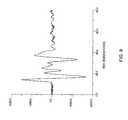
- FIG. 9is a graph of a received radar signal time series
- FIG. 10is a schematic of a critically refracted ray in a GPR system
- FIG. 11is a schematic of a critically refracted ray and a reflected ray in a GPR system
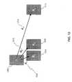
- FIG. 12is a schematic diagram of bi static measurements for computing wave speed
- FIG. 13is a diagram of a mobile vehicle with a GPR system
- FIG. 14is a diagram of a mobile vehicle with a GPR system.
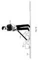
- FIG. 15is a diagram of a portable GPR system.
- FIG. 1is an embodiment of an apparatus for identifying buried objects using ground-penetrating radar consistent with the present invention.
- the apparatus of FIG. 1includes sensor unit 102 , data processor 104 , pre-processor 106 , image processor 108 , feature processor 110 , detector 112 , discriminator 114 , and display 116 .
- FIG. 2is a detailed view of sensor unit 102 .
- An embodiment of sensor unit 102 consistent with the present inventionincludes transmit antenna 202 and receive antenna 204 .
- Transmit antenna 202emits GPR waves used to probe for buried objects.
- Receive antenna 204receives the transmitted GPR waves as they are reflected from the ground and from objects located beneath the ground.
- Sensor unit 102controls the characteristics of the transmitted GPR signal (in some instances receiving support from data processor 104 as will be descried in greater detail below) and receives the reflected signal.
- Suitable antennas for the present inventioninclude, for example, small broadband antennas with a broad beam pattern having a frequence response spanning at least two octaves.
- Antenna 302has antenna transmitters (“T”) and receivers (“R”) arranged in a single line, with alternating transmitter and receiver elements.
- Antenna 304has one row of transmitter elements and a parallel row of receiver elements.
- Antenna 306has one row of transmitter elements and a parallel row of receiver elements with the receiver element row offset from the row of transmitter elements.
- Each antennacan have the same polarization or polarization can vary among the antennas. Additional antenna arrangements consistent with the present invention are described in U.S. Patent Provisional Application No. 60/152,607, filed Sep. 8, 1999, and in corresponding non provisional U.S. patent application Ser. No. 09/658,188, filed Sep. 8, 2000, now abandoned.
- FIG. 3depicts sensor units comprised of arrays of antenna elements
- an embodiment of sensor unit 102 consistent with the present inventionincludes a pair of transmit and receive antenna elements that are moved during data acquisition to simulate data acquisition using an array.
- transmit and receive antenna elementsthat are moved during data acquisition to simulate data acquisition using an array.
- FIG. 4illustrates an example of a direction of movement (indicated by the arrow) in antenna array configuration 302 with a single line of transmitter and receiver antenna elements.
- FIG. 5is a schematic diagram of data acquisition at three different time steps t 0 , t 1 , and t 2 (parts (a), (b), and (c), respectively) using the array configuration and scan direction shown in FIG. 4 . As shown in part (a) of FIG. 5, at time t 0 data are acquired over all antennas in the array at a fixed position x 0 .
- the antenna arrayis moved preferably by a fixed amount ⁇ x to position x 1 (FIG. 5 part (b). Once at position x 1 , data are acquired over all antennas in the array at the new position. Parts (b) and (c) of FIG. 5 include shaded antenna array elements showing the locations of the antenna elements at previous time steps.
- the antenna arrayis moved again by a fixed amount ⁇ x to position x 2 (FIG. 5, part (c)). Once at position x 2 , data are acquired over all antennas in the array at the new position. This process continues for a number of iterations sufficient to scan a region of interest over a buried object. Note also that scanning can also be non-linear, e.g., ⁇ x is not fixed at each time interval.
- Data processor 104can generate control signals that ensure proper operation of sensor unit 102 when acquiring data as illustrated in FIGS. 4 and 5. Moreover, data processor 104 processes data received by sensor unit 102 .
- Two techniques for acquiring and processing data using sensor unit 102 and data processor 104 consistent with the present inventionare mono static and multi static processing. In mono static data acquisition, data processor 104 assumes that a transmitting and receiving antenna are paired such that the data acquired simulates a single pair of antennas moved in unison.
- FIG. 6is a schematic diagram of the antenna array elements in a configuration of sensor unit 102 for mono static data acquisition. As shown in FIG.
- sensor unit 102fires transmit antenna element 602 a and then receive antenna element 602 b records the reflected GPR signal.
- sensor unit 102activates the next transmit and receive antenna elements 604 a and 604 b , respectively, in the array (FIG. 6, part (b)).
- the remaining transmit and receive antenna elementsare activated in pairs at successive time intervals, e.g., transmit element 606 a and receive element 606 b are activated during period t 2 (FIG. 6, part (c)), transmit element 608 a and receive element F 08 b are activated during period t 3 (FIG. 6, part (d)), etc.
- a transmittercan be paired with more than one receiver or vice versa.
- An embodiment of data processor 104 consistent with the present inventionincludes a mono static data processor that recognizes the manner in which sensor unit 102 acquires data representing the buried object. The mono static data processor then processes data accordingly to extract a signal representing the buried object.
- FIG. 7is a schematic diagram of multi static data acquisition.
- multi staticsometimes also referred to as bi static
- datais acquired at all receivers for every transmitter at each time period.
- transmit element 702fires and each of the receive elements 704 - 718 record the reflected GPR wave (FIG. 7, part (a)).
- transmit element 720fires and each of the receive elements 704 - 718 record the reflected GPR wave (FIG. 7, part (b)).
- t 3FIG.
- transmit elements 722 and 724respectively, fire and the resultant GPR waves are recorded by receive elements 704 - 718 .
- This processcontinues over successive time intervals until data acquisition processor 102 has activated each of the transmit antenna elements.
- this technique of multi static data acquisitioncan be performed by moving a pair of antenna elements to simulate data acquisition using an array.
- An embodiment of data processor 104 consistent with the present inventionincludes a multi static data processor that recognizes the manner in which sensor unit 102 acquires data representing the buried object. The multi static data processor then processes data accordingly to extract a signal representing the buried object.
- An embodiment of a multi static data acquisition processor consistent with the present inventionhas either a dedicated data acquisition channel for each receiver or a multiplexer for sequentially multiplexing through some lesser number of data acquisition channels.
- data processor 104 in the apparatus of FIG. 1performs system calibration operations including, for example, one or more of the following: time alignment, wave speed analysis, and impulse response function computation (which can include, for example, beam pattern and spectral response computations). Each of these operation is described in greater detail below.
- data processor 104processes data received from sensor unit 102 to extract a meaningful signal corresponding to buried object in a surveyed region.
- An embodiment of data processor 104 consistent with the present inventionis comprised of a processor that executes stored computer program code designed to implement calibration operations.
- data processor 104implemented entirely in software, entirely in hardware, or in an embodiment allocating calibration functions among hardware and software elements, either distributed or centralized, is consistent with the scope of the present invention.
- An embodiment of data processor 104 consistent with the present inventioncan include a time alignment calculator that performs time alignment to compensate for the difference in wave propagation speed in air versus its propagation speed in geological material.
- Electromagnetic waves generated by a GPR system consistent with the present inventiontravel at the speed of light through geological objects.
- electromagnetic signalstravel between controlling system electronics and the antennas at a propagation speed near that of the wave speed in the host medium. Accordingly, unless compensated for, this can prevent accurate absolute time registration, i.e., determining the actual time at which the transmitted wave leaves the transmitting antenna.
- electronic circuitrycan differ for each antenna pairing. Consequently, an embodiment of data processor 104 consistent with the present invention performs time alignment for each antenna pairing used in sensor unit 102 .
- an embodiment of data processor 104 consistent with the present inventioncan include a wave speed calculator to compute wave speed as described in greater detail below.
- Time alignmentis accomplished by recognizing that the wave sent from each transmitting antenna to each receiving antenna travels through air.
- the distance between any transmitter-receiver antenna pairis know.
- the distance between transmitting antenna element 802 and receiving antenna element 804is labeled “d.”
- the earliest arriving signalwill be from the air-propagated wave.
- data processor 104searches an acquired time series (FIG. 9) for the first arriving peak. As seen in FIG. 9, the peak at approximately twelve nanoseconds is the air-propagated arrival time and the peak at approximately forty nanoseconds in the ground-propagated arrival time. Data processor 104 then adjusts the acquired time series so that the arrival time of the first peak occurs at t air as determined from Eq. (1).
- a GPR apparatus consistent with the present inventionuses spatial correlations among time series acquired for various transmitter-receiver antenna element pairings.
- the travel distance ris related to the travel time t arrival by:
- Data processor 104computes the background wave speed c 0 .
- Data processor 104computes c 0 by exploiting the fact that there will be a critically refracted ray (FIG. 10, 1008 ) that will propagate at speed c 0 horizontally between a transmitter ( 1002 ) and receiver ( 1004 ) just below the air-ground interface ( 1006 ).
- This ground-propagated arrivalwill occur later than the direct air-propagated arrival. Since this is the shortest ground-propagated ray path, this arrival will precede any ray paths associated with reflections from sub surface objects.
- FIG. 11shows critically refracted ray path 1108 and ray path associated with a reflection 1110 a , 1110 b from sub surface object 1106 . Since ray path 1108 for the critically refracted ray is shorter than the ray path associated with a reflection 1110 a , 1110 b , the arrival of the ground-propagated ray will precede that of the reflection.
- FIG. 12is a schematic diagram of bi static measurements for computing wave speed.
- the distance from the transmitter to receiver iis denoted by d i .
- d 1is the distance 1206 between transmitting antenna (T) 1202 and receiving antenna (R 1 ) 1204
- d 2is the distance 1210 between transmitting antenna (T) 1202 and receiving antenna (R 2 ) 1208
- d nis the distance 1214 between transmitting antenna (T) 1202 and receiving antenna (R n ) 1212 .
- the distance usedis the distance from the transmitter to the receiver position.
- the first major arrivalis the air propagated arrival and the second major arrival is the critically refracted ground propagated arrival.
- t i 's and d 'scan be used and 1/c 0 is the slope of a linear fit for Eq. (3), e.g., the best linear fit.
- ringingWhen using an array of antennas, there may be arrivals intermediate to the air- and ground-propagated arrivals. These are typically air-propagated and associated with reflections or multiple reflections with the antenna array. These artifacts are referred to herein as “ringing” and will be manifested as peaks in the power spectra of the acquired data. It may be necessary to remove this ringing before computing wave speed. This can be done by identifying the spectral peaks and applying appropriate spectral band-pass filters, such as Blackman-Harris filters, known to those skilled in the art prior to implementing any of the above-described procedures.
- spectral band-pass filterssuch as Blackman-Harris filters
- the followingis an additional method for computing wave speed consistent with the present invention in a GPR system configured with a single transmitting antenna and one or more receiving antennas where the i th receiver is a distance d i away from the transmitting antenna (or when one receive element is used and moved to simulate an array, the distance used is the distance from the transmitter to the receiver position). If the transmitter is pulsed, the first two arriving signals at any receiver are transmitted through the air propagating at the wave speed in air, c a , and a critically refracted ray propagating just below the air-ground interface at a wave speed c g , where c g ⁇ c a .
- dis the transmitter-receiver separation and ⁇ g is the measured travel time of the critically refracted ray through the ground.
- ⁇ gis the measured travel time of the critically refracted ray through the ground.
- An embodiment of data processor 104can implement a variation of the above procedure using two receiving antennas at different distances from the transmitting antenna.
- S 1 and S 2be time series for transmitter-receiver spacings of d 1 and d 2 , respectively.
- a cross-correlation of the form F 1 - 2 ⁇ ( t )⁇ ⁇ ⁇ - ⁇ ⁇ ⁇ t ⁇ s 1 ⁇ ( ⁇ ) ⁇ s 2 * ⁇ ( ⁇ ) s 1 ⁇ ( ⁇ ) ⁇ s 1 * ⁇ ( ⁇ ) + ⁇ , ( 11 )
- ⁇ a 1 and ⁇ g 1are the air and ground propagated travel times, respectively, for the i th receiver.
- ⁇ a 1 and ⁇ g 1are the air and ground propagated travel times, respectively, for the i th receiver.
- Ground penetrating radar antennashave spatially three-dimensional beam patterns that are frequency dependent. While it is possible to characterize these beam patterns by direct propagation measurements in air, these patterns will change when the antennas are dynamically coupled to a material with a dielectric or electrical conductivity that is different from air.
- data processor 104characterizes antenna beam patterns from any array geometry by acquiring data over an object having a known location and known electromagnetic properties.
- the wave field ucan be considered as the superposition of u 0 , the wavefield that would exist in the absence of a buried object and u′, the perturbation to u 0 associated with the known buried object.
- ⁇ 0is the free-space magnetic permeability
- ⁇ 0 and ⁇ (r)are background and object dielectric constants, respectively
- ⁇ 0 and ⁇ (r)are the background and object electrical conductivities, respectively. Since any object can be buried, a relatively small object can be selected such that the Born approximation is valid, in which case, the background wave field u 0 can be used in place of the total field u in Eq.
- Equation (16)can be used by data processor 104 for forwarding modeling where, given O, u′ is computed.
- data processor 104can use this equation for inverse scattering where O is determined from known u 0 and measured u′.
- Ois determined from known u 0 and measured u′.
- u 0 and Oare known
- u′is measured for a measurement configuration of interest
- Eq. (16)is used by data processor 104 to determine the impulse response function of the antenna array that includes the effects of the unknown beam pattern.
- G ⁇ ( r - r ′ ; k 0 )i ⁇ ⁇ d ⁇ ⁇ ⁇ k 0 2 - ⁇ 2 ⁇ A R ⁇ ( ⁇ ; k 0 ) ⁇ ⁇ ⁇ ⁇ [ ⁇ ⁇ ( r - r ′ ) + k 0 2 - ⁇ 2 ⁇ ⁇ z ⁇ ⁇ ⁇ ( r - r ′ ) ⁇ ] ( 18 )
- factor A Ris included to represent the unknown receiving antenna beam pattern.
- ⁇ ′( ⁇ , ⁇ ; k 0 )⁇ dr ⁇ dr 0 u′ ( r, r 0 ; k 0 ) e ⁇ i( ⁇ r ⁇ r 0 ) (20)
- ⁇ ′( ⁇ , ⁇ ; k 0 )⁇ ( ⁇ , ⁇ ; k 0 ) I (( ⁇ , ⁇ ; k 0 ) ⁇ , (21)
- ⁇is the two-dimensional spatial Fourier transform of A R A T
- Iis the impulse response function for monopole sources
- ⁇is the three-dimensional spatial Fourier transform of the object function.
- the arrayincluding the antenna beam patterns and spectral respnses in terms of the known O and measured u′.
- Arrays that are not fully bi staticare either fully mono static or bi static in one direction and mono static in the other. Accordingly, for these geometries, additional assumptions or approximations can be used by data processor 104 for deconvolving Eq. (16).
- One suitable assumptionis that the object is buried about one wavelength deep or deeper. Since the burial depth of the reference object can be controlled during calibration, the validity of this assumption can be assured and a valid relationship such as that given by Eq. (16) can be developed.
- data processor 104detects spatial correlations corresponding to the buried object in data from the GPR sensors.
- preprocessor 106The next element of the GPR systems of FIG. 1 is preprocessor 106 .
- An embodiment of preprocessor 106 consistent with the present inventionis comprised of a processor that executes stored computer program code designed to implement preprocessing operations.
- preprocessor 106implemented entirely in software, entirely in hardware, or in an embodiment allocating preprocessing functions among hardware and software elements, either distributed or centralized, is consistent with the scope of the present invention.
- Preprocessor 106rejects elements in the acquired data associated with unwanted sub surface features and/or admits only targets of interest. For example, consider spatial frequency preprocessing of mono static data. Frequently reflections from soil or geological strata produce strong reflections that can obscure other features of interest. These strata typically are nearly planar and horizontal. The two-dimensional spatial Fourier transform of a horizontal surface will be a delta function at the spatial frequency origin. An embodiment of preprocessor 106 consistent with the present invention removes such a feature using a notch filter for filtering a DC response. Since most naturally occurring strata are not perfectly horizontal, and may not be truly planar, preprocessor 106 relaxes the notched filter somewhat into a low-cut filter (e.g., “high-pass filter) to substantially suppress these strata.
- a low-cut filtere.g., “high-pass filter
- a Blackman-Harris filteris an example of an appropriate filter for this purpose. Similar spatial frequency filters can be used to admit features of interest. If targets of interest are buried utilities, for example, these have the rather unique characteristic of being long and thin. The spatial Fourier transform of such a shape will generate a DC response in the axial direction and a white response in the transverse direction. Thus, preprocessor 106 applies an appropriate filter to admit features having these characteristics.
- Image processor 108builds a data structure corresponding to an image of the buried object from the data processed by data processor 104 .
- Image processor 108can, for example, reconstruct the location, size, shape, and material properties of sub surface features in two-dimensions, three-dimensions, or as a sequence of two-dimensional images.
- An embodiment of image processor 108 consistent with the present inventionis comprised of a processor that executes stored computer program code designed to implement image processing operations.
- image processor 108implemented entirely in software, entirely in hardware, or in an embodiment allocating image processing functions among hardware and software elements, either distributed or centralized, is consistent with the scope of the present invention.
- Embodiments of image processor 108implement image processing algorithms including, but not limited to, synthetic aperture radar (SAR), migration, backpropagation, diffraction tomography, algebraic reconstruction tomography (ART), iterative ART, pseudo-inverse, and reverse time processing.
- SARsynthetic aperture radar
- ARTalgebraic reconstruction tomography
- ARTiterative ART
- pseudo-inversepseudo-inverse
- reverse time processingOne skilled in the art will recognize that other image processing algorithms are also suitable for implementing the functions performed by image processor 108 .
- some operations performed by preprocessor 106can be incorporated directly into many of these imaging procedures of image processor 108 by introducing filters into the impulse response function.
- Feature processor 110processes a received GPR signal to characterize features present in the signal that correspond to properties of a detected buried object.
- An embodiment of feature processor 110 consistent with the present inventionis comprised of a processor that executes stored computer program code designed to implement feature processor operations.
- One skilled in the artwill recognize that an embodiment of feature processor 110 implemented entirely in software, entirely in hardware, or in an embodiment allocating feature processor functions among hardware and software elements, either distributed or centralized, is consistent with the scope of the present invention.
- Feature processor 110differentiates the GPR signal to characterize features based on differences in reconstructed material properties.
- An embodiment of feature processor 110uses frequency domain processing, performing an inverse operation mapping frequency information to depth.
- L ⁇ 1be the operator that maps the broadband data into the image, i.e.,
- equations 23-27can be extended to accommodate processing a GPR signal that propagated through a conducting background.
- Feature processor 110accomplishes further differentiation by recognizing how O ⁇ and O 94 are related for certain material types. For example, plastic objects are characterized by low dielectric and low conductivity. Consequently, feature processor 110 recognizes that plastic objects exhibit an O ⁇ that is greater than background (positive) and an O 94 that is, in general, less than background (negative). The converse is generally true for metal objects. For this reason, feature processor 110 generates an enhanced data set forming a picture of metal or plastic objects by examining O ⁇ ⁇ O ⁇ . For metal objects, this difference could be strongly negative while, for plastic objects, it could be strongly positive. For other materials such as clay, wood, and concrete; feature processor 110 enhances features using the sum O ⁇ +O 94 .
- Detector 112automatically identifies targets of interest.
- An embodiment of detector 112 consistent with the present inventionis comprised of a processor that executes stored computer program code designed to implement detection operations.
- One skilled in the artwill recognize that an embodiment of detector 112 implemented entirely in software, entirely in hardware, or in an embodiment allocating detection functions among hardware and software elements, either distributed or centralized, is consistent with the scope of the present invention.
- Detector 112determines whether an object detected in a surveyed region matches a predetermined target or belongs to a predefined target class. If the object in the surveyed region does match, detector 112 identifies the location of the object.
- An embodiment of detector 112uses matched filters to compare a signal representing an object in a surveyed region to targets and target classes.
- u(r, ⁇ )is the acquired data over a measurement surface defined by r over a bandwidth spanned by ⁇ .
- ⁇ (r, ⁇ ; x 0 )is the data that would be acquired if the target of interest were centered at the point x 0 .
- detector 112Many other detection algorithms are suitable for implementation by detector 112 such, for example, Baysian statistics or the MUSIC algorithm.
- Descriminator 114is a signal processing element similar to detector 112 (described in detail above); however, descriminator 114 processes images reconstructed from received GPR signal data rather than processing the acquired GPR signal data directly.
- An embodiment of descriminator 114 consistent with the present inventionis comprised of a processor that executes stored computer program code designed to implement descriminator operations.
- One skilled in the artwill recognize that an embodiment of descriminator 114 implemented entirely in software, entirely in hardware, or in an embodiment allocating descriminator functions among hardware and software elements, either distributed or centralized, is consistent with the scope of the present invention.
- an embodiment of descriminator 114performs a correlation operation similar to Eq. (28), but applied to images reconstructed from received GPR signal data.
- Other embodiments of descriminator 114implement feature extraction algorithms, pattern recognition algorithms, and/or feature tracking algorithms that track a feature identified in one portion of the image throughout the entire image.
- Display 116proves an operator of the GPR system with visual feedback representing the surveyed region.
- An embodiment of display 116 consistent with the present inventionis comprised of a graphical display device that can present an image to an operator (e.g., video screen, plotter, printer, etc.) and a processor that executes stored computer program code designed to implement display operations.
- an embodiment of display 116implemented entirely in software, entirely in hardware, or in an embodiment allocating display functions among hardware and software elements, either distributed or centralized, is consistent with the scope of the present invention.
- the image presented to the operatortakes the form of a three-dimensional rendering of the surveyed site or a sequence of two-dimensional images of the reconstruction.
- the reconstructionscan be of a basic material property, such as dielectric, or a composite of multiple properties, such as reflectivity, object function or some statistical estimator.
- Other embodiments of display 116 consistent with the present inventionpresent images to the operator as projections of reconstructed information onto a plane such as the ground surface.
- the GPR system functions described for each of the elements abovecan be distributed or combined differently than stated above and still fall within the scope of the invention.
- the GPR systemcan be implemented using a single processor or group of processors that execute software stored in a central memory, wherein the software relates to each of the above-described GPR system operations.
- the operation of the GPR system elements as defined aboveprovide an efficient system to rapidly and accurately locate buried objects. Therefore, in accordance with the present invention, the disclosed GPR system elements can be housed in many types of structures, including portable and mobile structures to allow rapid and accurate real-time surveying of a region of interest.
- FIG. 13is a diagram of a mobile vehicle 1304 with a GPR system, consistent with this invention.
- a radar array 1306attaches to an arm 1305 , which attaches to the back a vehicle 1304 , as shown in FIG. 13 .
- Radar array 1306may comprise at least one transmit antenna and at least one receive antenna.
- Vehicle 1304may move in direction shown by arrow 1302 .
- Radar array 1306transmits impulses into ground 1308 .
- the impulsesmay reflect off of a buried object, such as subterranean pipe 1312 and radar array 1306 may receive reflected waveforms.
- Module 1314 on the back of vehicle 1304may comprise elements described in greater detail above for FIG. 1, which control array 1306 and process signals received by array 1306 . It may also display on display 1316 images of buried objects from data acquired by sensor unit 102 in the surveyed region of interest (with or without images of the surrounding area).
- FIG. 14is a diagram, consistent with this invention, of mobile vehicle 1404 with a trailer 1402 having a GPR system.
- radar array 1306(not shown in FIG. 14) is within trailer 1402 , which is attached to vehicle 1404 .
- Trailer 1402moves in the direction of arrow 1410 with vehicle 1404 .
- FIG. 15is a diagram, consistent with this invention, of a portable housing 1504 with a GPR system.
- radar array 1306(not shown in FIG. 14) is within portable housing 1504 .
- a user 1502may guide portable housing 1504 over ground 1308 using handle 1506 .
- Portable housing 1504may have wheels 1508 , skid pads (not shown), or neither.
- An embodiment of portable housing 1504can also be made sufficiently light to allow an operator to carry the entire system, thereby alleviating the need for wheels, skid pads, or similar structure to guide the housing over the ground.
- Both the mobile system of FIG. 14 and the portable system of FIG. 15may also display images of buried objects from data acquired by the sensor unit in the surveyed region of interest (with or without images of the surrounding area).
- a GPR system consistent with the present inventioncan overcome the disadvantages of One Call, private locating, and SUE by providing a cost effective method to locate and image conductive and non-conductive utilities, vertically and horizontally, with a margin of error to satisfy many excavating needs.
- a GPR system consistent with the present inventioncan also provide a permanent record of images of the excavation site that can be used in the future.
- a GPR system consistent with the present inventioncan fit onto a moving vehicle, trailer, or portable housing so that sub surface images can be formed as the system is moving.
Landscapes
- Engineering & Computer Science (AREA)
- Remote Sensing (AREA)
- Physics & Mathematics (AREA)
- Radar, Positioning & Navigation (AREA)
- General Physics & Mathematics (AREA)
- Life Sciences & Earth Sciences (AREA)
- Electromagnetism (AREA)
- Computer Networks & Wireless Communication (AREA)
- Environmental & Geological Engineering (AREA)
- Geology (AREA)
- General Life Sciences & Earth Sciences (AREA)
- Geophysics (AREA)
- Radar Systems Or Details Thereof (AREA)
- Geophysics And Detection Of Objects (AREA)
Abstract
Description


Claims (31)
Priority Applications (7)
| Application Number | Priority Date | Filing Date | Title |
|---|---|---|---|
| US10/118,991US6700526B2 (en) | 2000-09-08 | 2002-04-10 | Method and apparatus for identifying buried objects using ground penetrating radar |
| EP02764144AEP1393098A2 (en) | 2001-04-20 | 2002-04-22 | A method and apparatus for identifying buried objects using ground penetrating radar |
| CN02812267.4ACN1228648C (en) | 2001-04-20 | 2002-04-22 | A method and apparatus for identifying buried objects using ground penetrating radar |
| PCT/US2002/008274WO2002086542A2 (en) | 2001-04-20 | 2002-04-22 | A method and apparatus for identifying buried objects using ground penetrating radar |
| AU2002338452AAU2002338452A1 (en) | 2001-04-20 | 2002-04-22 | A method and apparatus for identifying buried objects using ground penetrating radar |
| JP2002584015AJP2005503539A (en) | 2001-04-20 | 2002-04-22 | Method and apparatus for identifying buried objects using underground search radar |
| US10/769,965US7034740B2 (en) | 2000-09-08 | 2004-02-02 | Method and apparatus for identifying buried objects using ground penetrating radar |
Applications Claiming Priority (5)
| Application Number | Priority Date | Filing Date | Title |
|---|---|---|---|
| US65818800A | 2000-09-08 | 2000-09-08 | |
| US28492101P | 2001-04-20 | 2001-04-20 | |
| US86657501A | 2001-05-29 | 2001-05-29 | |
| US10/079,807US20030043067A1 (en) | 1999-09-08 | 2002-02-22 | Ground penetrating radar array and timing circuit |
| US10/118,991US6700526B2 (en) | 2000-09-08 | 2002-04-10 | Method and apparatus for identifying buried objects using ground penetrating radar |
Related Parent Applications (1)
| Application Number | Title | Priority Date | Filing Date |
|---|---|---|---|
| US10/079,807Continuation-In-PartUS20030043067A1 (en) | 1999-09-08 | 2002-02-22 | Ground penetrating radar array and timing circuit |
Related Child Applications (1)
| Application Number | Title | Priority Date | Filing Date |
|---|---|---|---|
| US10/769,965ContinuationUS7034740B2 (en) | 2000-09-08 | 2004-02-02 | Method and apparatus for identifying buried objects using ground penetrating radar |
Publications (2)
| Publication Number | Publication Date |
|---|---|
| US20030076254A1 US20030076254A1 (en) | 2003-04-24 |
| US6700526B2true US6700526B2 (en) | 2004-03-02 |
Family
ID=26816949
Family Applications (2)
| Application Number | Title | Priority Date | Filing Date |
|---|---|---|---|
| US10/118,991Expired - LifetimeUS6700526B2 (en) | 2000-09-08 | 2002-04-10 | Method and apparatus for identifying buried objects using ground penetrating radar |
| US10/769,965Expired - Fee RelatedUS7034740B2 (en) | 2000-09-08 | 2004-02-02 | Method and apparatus for identifying buried objects using ground penetrating radar |
Family Applications After (1)
| Application Number | Title | Priority Date | Filing Date |
|---|---|---|---|
| US10/769,965Expired - Fee RelatedUS7034740B2 (en) | 2000-09-08 | 2004-02-02 | Method and apparatus for identifying buried objects using ground penetrating radar |
Country Status (6)
| Country | Link |
|---|---|
| US (2) | US6700526B2 (en) |
| EP (1) | EP1393098A2 (en) |
| JP (1) | JP2005503539A (en) |
| CN (1) | CN1228648C (en) |
| AU (1) | AU2002338452A1 (en) |
| WO (1) | WO2002086542A2 (en) |
Cited By (73)
| Publication number | Priority date | Publication date | Assignee | Title |
|---|---|---|---|---|
| US20040090359A1 (en)* | 2001-03-16 | 2004-05-13 | Mcmakin Douglas L. | Detecting concealed objects at a checkpoint |
| US20040140924A1 (en)* | 2001-03-16 | 2004-07-22 | Keller Paul E. | Detection of a concealed object |
| US20040155810A1 (en)* | 2000-09-08 | 2004-08-12 | Witten Technologies, Inc. | Method and apparatus for identifying buried objects using ground penetrating radar |
| US20040225444A1 (en)* | 2000-06-14 | 2004-11-11 | Vermeer Manufacturing Company | Underground utility detection system and method |
| US20040263379A1 (en)* | 2003-06-26 | 2004-12-30 | Keller Paul E. | Concealed object detection |
| US20050027769A1 (en)* | 2003-07-28 | 2005-02-03 | Alan Witten | Method for reconstructing complex wave attributes from limited view measurements |
| WO2005096019A1 (en)* | 2004-04-03 | 2005-10-13 | Statoil Asa | Electromagnetic data processing |
| US20060066469A1 (en)* | 2004-09-24 | 2006-03-30 | Foote Harlan P | Three-dimensional surface/contour processing based on electromagnetic radiation interrogation |
| US20060077095A1 (en)* | 2004-07-20 | 2006-04-13 | Tucker Layne D | Precision GPS driven utility asset management and utility damage prevention system and method |
| US20070035437A1 (en)* | 2005-05-31 | 2007-02-15 | L-3 Communications Cyterra Corporation | Computerized Tomography Using Radar |
| US20070258325A1 (en)* | 2006-05-02 | 2007-11-08 | Mark Grasmueck | Rotary laser positioning for geophysical sensing |
| US20070263907A1 (en)* | 2006-05-15 | 2007-11-15 | Battelle Memorial Institute | Imaging systems and methods for obtaining and using biometric information |
| US20080079723A1 (en)* | 2006-05-16 | 2008-04-03 | David Hanson | System and method for visualizing multiple-sensor subsurface imaging data |
| US20080143581A1 (en)* | 2006-12-19 | 2008-06-19 | Bellsouth Intellectual Property Corporation | Scanning and projection systems and methods |
| US20080169961A1 (en)* | 2005-05-31 | 2008-07-17 | L-3 Communications Cyterra Corporation | Computerized Tomography Using Radar |
| US20090013928A1 (en)* | 2007-04-04 | 2009-01-15 | Certusview Technologies, Llc | Marking system and method |
| US7511654B1 (en) | 2006-01-12 | 2009-03-31 | The United States Of America As Represented By The Secretary Of The Army | Systems and methods for mine detection |
| US20090134877A1 (en)* | 2005-02-01 | 2009-05-28 | Tor Schaug-Pettersen | Optimum signal for sea bed logging |
| US7548192B1 (en)* | 2008-02-07 | 2009-06-16 | Fdh Engineering, Inc. | Method of mapping steel reinforcements in concrete foundations |
| US20090201178A1 (en)* | 2007-03-13 | 2009-08-13 | Nielsen Steven E | Methods for evaluating operation of marking apparatus |
| US20090204238A1 (en)* | 2007-03-13 | 2009-08-13 | Nielsen Steven E | Electronically controlled marking apparatus and methods |
| US20090202111A1 (en)* | 2008-02-12 | 2009-08-13 | Steven Nielsen | Electronic manifest of underground facility locate marks |
| US7586433B1 (en) | 2007-03-26 | 2009-09-08 | Mala Geoscience Ab | Dual port memory trigger system for a ground penetrating radar |
| US7606530B1 (en) | 2006-03-11 | 2009-10-20 | Rockwell Collins, Inc. | RFID system for allowing access to remotely positioned RFID tags |
| US20100045517A1 (en)* | 2004-07-20 | 2010-02-25 | Global Precision Solutions, Llp | Precision GPS Driven Utility Asset Management and Utility Damage Prevention System and Method |
| US20100052688A1 (en)* | 2006-02-09 | 2010-03-04 | Electromagnetic Geoservices As | Electromagnetic surveying |
| US20100088164A1 (en)* | 2008-10-02 | 2010-04-08 | Certusview Technologies, Llc | Methods and apparatus for analyzing locate and marking operations with respect to facilities maps |
| US20100085185A1 (en)* | 2008-10-02 | 2010-04-08 | Certusview Technologies, Llc | Methods and apparatus for generating electronic records of locate operations |
| US20100085376A1 (en)* | 2008-10-02 | 2010-04-08 | Certusview Technologies, Llc | Methods and apparatus for displaying an electronic rendering of a marking operation based on an electronic record of marking information |
| US20100085701A1 (en)* | 2008-10-02 | 2010-04-08 | Certusview Technologies, Llc | Marking device docking stations having security features and methods of using same |
| US20100088031A1 (en)* | 2008-10-02 | 2010-04-08 | Certusview Technologies, Llc | Methods and apparatus for generating an electronic record of environmental landmarks based on marking device actuations |
| US20100188216A1 (en)* | 2008-10-02 | 2010-07-29 | Certusview Technologies, Llc | Methods and apparatus for generating alerts on a locate device, based on comparing electronic locate information to facilities map information and/or other image information |
| US20100188215A1 (en)* | 2008-10-02 | 2010-07-29 | Certusview Technologies, Llc | Methods and apparatus for generating alerts on a marking device, based on comparing electronic marking information to facilities map information and/or other image information |
| US20100188088A1 (en)* | 2008-10-02 | 2010-07-29 | Certusview Technologies, Llc | Methods and apparatus for displaying and processing facilities map information and/or other image information on a locate device |
| US20100188407A1 (en)* | 2008-10-02 | 2010-07-29 | Certusview Technologies, Llc | Methods and apparatus for displaying and processing facilities map information and/or other image information on a marking device |
| US20100189887A1 (en)* | 2008-10-02 | 2010-07-29 | Certusview Technologies, Llc | Marking apparatus having enhanced features for underground facility marking operations, and associated methods and systems |
| US20100189312A1 (en)* | 2008-10-02 | 2010-07-29 | Certusview Technologies, Llc | Methods and apparatus for overlaying electronic locate information on facilities map information and/or other image information displayed on a locate device |
| US20100188245A1 (en)* | 2008-10-02 | 2010-07-29 | Certusview Technologies, Llc | Locate apparatus having enhanced features for underground facility locate operations, and associated methods and systems |
| US20100198663A1 (en)* | 2008-10-02 | 2010-08-05 | Certusview Technologies, Llc | Methods and apparatus for overlaying electronic marking information on facilities map information and/or other image information displayed on a marking device |
| US20100231223A1 (en)* | 2006-06-09 | 2010-09-16 | Electromagnetic Geoservices Asa | Instrument for measuring electromagnetic signals |
| US20100259438A1 (en)* | 2006-05-16 | 2010-10-14 | Ross Peter Jones | Sensor cart positioning system and method |
| US20110045175A1 (en)* | 2009-08-20 | 2011-02-24 | Certusview Technologies, Llc | Methods and marking devices with mechanisms for indicating and/or detecting marking material color |
| US20110060549A1 (en)* | 2009-08-20 | 2011-03-10 | Certusview Technologies, Llc | Methods and apparatus for assessing marking operations based on acceleration information |
| US20110115667A1 (en)* | 2009-11-17 | 2011-05-19 | Geophysical Survey Systems, Inc. | Ultra-wideband Radar Waveform Calibration for Measurements of a Heterogeneous Material |
| US20110117272A1 (en)* | 2009-08-20 | 2011-05-19 | Certusview Technologies, Llc | Marking device with transmitter for triangulating location during locate operations |
| US20110115666A1 (en)* | 2009-11-17 | 2011-05-19 | Geophysical Survey Systems, Inc. | Highway Speed Ground Penetrating Radar System Utilizing Air-Launched Antenna and Method of Use |
| US20110191058A1 (en)* | 2009-08-11 | 2011-08-04 | Certusview Technologies, Llc | Locating equipment communicatively coupled to or equipped with a mobile/portable device |
| US8040272B1 (en) | 2007-04-20 | 2011-10-18 | Niitek Inc. | Leading and lagging aperture for linear ground penetrating radar array |
| US8044838B1 (en)* | 2008-08-13 | 2011-10-25 | The Boeing Company | Methods and systems for determining the phase constant for a dielectric medium |
| US8063813B1 (en)* | 2008-04-14 | 2011-11-22 | Nokomis, Inc. | Active improvised explosive device (IED) electronic signature detection |
| US8086426B2 (en) | 2004-01-09 | 2011-12-27 | Statoil Asa | Processing seismic data representing a physical system |
| US8315804B2 (en) | 2007-01-09 | 2012-11-20 | Statoilhydro Asa | Method of and apparatus for analyzing data from an electromagnetic survey |
| US8314608B2 (en) | 2010-06-30 | 2012-11-20 | Hall David R | Method of determining distance to a ferrous material |
| US8473209B2 (en) | 2007-03-13 | 2013-06-25 | Certusview Technologies, Llc | Marking apparatus and marking methods using marking dispenser with machine-readable ID mechanism |
| US20140232586A1 (en)* | 2013-02-19 | 2014-08-21 | Infineon Technologies Ag | Method and Device for Radar Applications |
| US8913463B2 (en) | 2006-10-12 | 2014-12-16 | Electromagnetic Geoservices Asa | Positioning system |
| US8917199B2 (en) | 2011-04-13 | 2014-12-23 | Raytheon Company | Subterranean image generating device and associated method |
| US20150042508A1 (en)* | 2013-08-09 | 2015-02-12 | Electronics And Telecommunications Research Institute | Method and apparatus for reconstructing dielectric image using electromagnetic waves |
| US8957809B2 (en) | 2012-07-18 | 2015-02-17 | Geophysical Survey Systems, Inc. | Merged ground penetrating radar display for multiple antennas |
| US9004004B2 (en) | 2008-07-10 | 2015-04-14 | Certusview Technologies, Llc | Optical sensing methods and apparatus for detecting a color of a marking substance |
| US9052394B2 (en) | 2009-10-06 | 2015-06-09 | Louisiana Tech University Research Foundation | Method and apparatus for detecting buried objects |
| US20160131738A1 (en)* | 2013-06-05 | 2016-05-12 | Airbus Defence and Space GmbH | Multi-Functional Radar Assembly |
| US9348020B2 (en) | 2012-03-12 | 2016-05-24 | Vermeer Manufacturing Company | Offset frequency homodyne ground penetrating radar |
| US9372117B2 (en) | 2012-02-13 | 2016-06-21 | SeeScan, Inc. | Optical ground tracking apparatus, systems, and methods |
| US9684090B1 (en) | 2013-12-23 | 2017-06-20 | SeeScan, Inc. | Nulled-signal utility locating devices, systems, and methods |
| US9696448B2 (en) | 2010-06-15 | 2017-07-04 | SeeScan, Inc. | Ground tracking devices and methods for use with a utility locator |
| US9739133B2 (en) | 2013-03-15 | 2017-08-22 | Vermeer Corporation | Imaging underground objects using spatial sampling customization |
| US10054668B2 (en) | 2015-02-26 | 2018-08-21 | Src, Inc. | Probabilistic signal, detection, and track processing architecture and system |
| US10234552B1 (en) | 2018-06-27 | 2019-03-19 | University Of South Florida | Precise infrastructure mapping using full-waveform inversion of ground penetrating radar signals |
| WO2019168559A3 (en)* | 2017-09-01 | 2019-10-17 | Massachusetts Institute Of Technology | Surface penetrating radar and battery systems |
| US10448864B1 (en) | 2017-02-24 | 2019-10-22 | Nokomis, Inc. | Apparatus and method to identify and measure gas concentrations |
| US11489847B1 (en) | 2018-02-14 | 2022-11-01 | Nokomis, Inc. | System and method for physically detecting, identifying, and diagnosing medical electronic devices connectable to a network |
| US20230266461A1 (en)* | 2020-06-30 | 2023-08-24 | Commissariat A L’Energie Atomique Et Aux Energies Alternatives | Target detection method for ground-penetrating radar and associated radar |
Families Citing this family (78)
| Publication number | Priority date | Publication date | Assignee | Title |
|---|---|---|---|---|
| US6959982B2 (en)* | 1998-06-09 | 2005-11-01 | Silverbrook Research Pty Ltd | Flexible wall driven inkjet printhead nozzle |
| US6982666B2 (en)* | 2001-06-08 | 2006-01-03 | The United States Of America As Represented By The Secretary Of The Navy | Three-dimensional synthetic aperture radar for mine detection and other uses |
| US6674391B2 (en)* | 2002-05-08 | 2004-01-06 | Lockheed Martin Corporation | System and method of simulated image reconstruction |
| US20050104771A1 (en)* | 2003-09-17 | 2005-05-19 | Spectrotech, Inc. | Airborne imaging spectrometry system and method |
| NL1024427C2 (en)* | 2003-10-01 | 2005-04-05 | Arcadis Geo En Vastgoedinforma | Device is for contactless measurement of underground structure and uses ground radar, whereby an active ground radar unit is moved along a number of parallel running measurement lines |
| US8335814B2 (en)* | 2004-03-31 | 2012-12-18 | The Invention Science Fund I, Llc | Transmission of aggregated mote-associated index data |
| US20050255841A1 (en)* | 2004-05-12 | 2005-11-17 | Searete Llc | Transmission of mote-associated log data |
| US7929914B2 (en)* | 2004-03-31 | 2011-04-19 | The Invention Science Fund I, Llc | Mote networks using directional antenna techniques |
| US8275824B2 (en)* | 2004-03-31 | 2012-09-25 | The Invention Science Fund I, Llc | Occurrence data detection and storage for mote networks |
| US20050267960A1 (en)* | 2004-05-12 | 2005-12-01 | Searete Llc, A Limited Liability Corporation Of The State Of Delaware | Mote-associated log creation |
| US7389295B2 (en)* | 2004-06-25 | 2008-06-17 | Searete Llc | Using federated mote-associated logs |
| US9062992B2 (en)* | 2004-07-27 | 2015-06-23 | TriPlay Inc. | Using mote-associated indexes |
| US20050256667A1 (en)* | 2004-05-12 | 2005-11-17 | Searete Llc, A Limited Liability Corporation Of The State Of Delaware | Federating mote-associated log data |
| US7536388B2 (en)* | 2004-03-31 | 2009-05-19 | Searete, Llc | Data storage for distributed sensor networks |
| US20050227686A1 (en)* | 2004-03-31 | 2005-10-13 | Jung Edward K Y | Federating mote-associated index data |
| US20060064402A1 (en)* | 2004-07-27 | 2006-03-23 | Jung Edward K Y | Using federated mote-associated indexes |
| US7457834B2 (en) | 2004-07-30 | 2008-11-25 | Searete, Llc | Aggregation and retrieval of network sensor data |
| US8161097B2 (en)* | 2004-03-31 | 2012-04-17 | The Invention Science Fund I, Llc | Aggregating mote-associated index data |
| US8346846B2 (en)* | 2004-05-12 | 2013-01-01 | The Invention Science Fund I, Llc | Transmission of aggregated mote-associated log data |
| US7941188B2 (en) | 2004-03-31 | 2011-05-10 | The Invention Science Fund I, Llc | Occurrence data detection and storage for generalized sensor networks |
| US7599696B2 (en)* | 2004-06-25 | 2009-10-06 | Searete, Llc | Frequency reuse techniques in mote-appropriate networks |
| US9261383B2 (en) | 2004-07-30 | 2016-02-16 | Triplay, Inc. | Discovery of occurrence-data |
| US7725080B2 (en)* | 2004-03-31 | 2010-05-25 | The Invention Science Fund I, Llc | Mote networks having directional antennas |
| US20060004888A1 (en)* | 2004-05-21 | 2006-01-05 | Searete Llc, A Limited Liability Corporation Of The State Delaware | Using mote-associated logs |
| WO2005094494A2 (en)* | 2004-03-31 | 2005-10-13 | Searete Llc | Aggregating mote-associated index data |
| US8200744B2 (en)* | 2004-03-31 | 2012-06-12 | The Invention Science Fund I, Llc | Mote-associated index creation |
| US20060062252A1 (en)* | 2004-06-30 | 2006-03-23 | Jung Edward K | Mote appropriate network power reduction techniques |
| US20050265388A1 (en)* | 2004-05-12 | 2005-12-01 | Searete Llc, A Limited Liability Corporation Of The State Of Delaware | Aggregating mote-associated log data |
| US8253619B2 (en) | 2005-02-15 | 2012-08-28 | Techtronic Power Tools Technology Limited | Electromagnetic scanning imager |
| DE102005052367A1 (en)* | 2005-10-31 | 2007-05-03 | Robert Bosch Gmbh | Measuring device for detecting wires or pipes in walls, ceilings and floors comprises a high frequency sensor arranged in a housing and having a first antenna arrangement with antenna elements |
| SE530696C2 (en)* | 2006-12-19 | 2008-08-19 | Radarbolaget I Gaevle Ab | Method and apparatus for detecting movement of the surface of an object |
| US7898456B2 (en)* | 2008-02-19 | 2011-03-01 | Prairielands Energy Marketing Inc. | Apparatus and method for detecting and locating hidden objects |
| EP2128649A1 (en)* | 2008-05-28 | 2009-12-02 | Leica Geosystems AG | Radar measuring device with a planar aerial arrangement |
| WO2010014859A2 (en)* | 2008-07-30 | 2010-02-04 | Sal Amarillas | Device and method to evaluate condition of concrete roadways employing a radar-based sensing and data acquisition system |
| US8212710B2 (en) | 2008-10-31 | 2012-07-03 | Raytheon Company | Radar image generation system |
| DE102008054448A1 (en)* | 2008-12-10 | 2010-06-17 | Robert Bosch Gmbh | tracking device |
| US8130904B2 (en)* | 2009-01-29 | 2012-03-06 | The Invention Science Fund I, Llc | Diagnostic delivery service |
| US8047714B2 (en)* | 2009-01-29 | 2011-11-01 | The Invention Science Fund I, Llc | Diagnostic delivery service |
| DE102010014795A1 (en)* | 2010-01-08 | 2011-07-14 | Rohde & Schwarz GmbH & Co. KG, 81671 | Device for detecting and locating explosives in body to be examined, has contact unit connected with transmission- and receiving unit, where flexible surface area of contact unit is adapted to contour of body |
| KR101191387B1 (en)* | 2010-03-22 | 2012-10-18 | 한국전자통신연구원 | Two dimensional array antenna and object detection device using the same |
| US8625006B2 (en)* | 2010-07-26 | 2014-01-07 | Sony Corporation | Active imaging device and method for speckle noise reduction |
| US8681036B2 (en)* | 2010-08-26 | 2014-03-25 | Lawrence Livermore National Security, Llc | Distributed road assessment system |
| CN102004240B (en)* | 2010-10-25 | 2012-08-22 | 天津大学 | Unknown target detection signal reference waveform extraction method based on antenna array |
| WO2012097416A1 (en)* | 2011-01-20 | 2012-07-26 | Minelab Electronics Pty Limited | Incorporation and use of a position sensor in a metal detector |
| EP2506040A1 (en)* | 2011-04-01 | 2012-10-03 | Université Catholique De Louvain | Method and device for characterization of physical properties of a target volume by electromagnetic inspection. |
| US9329263B2 (en)* | 2011-05-23 | 2016-05-03 | The Regents Of The University Of Michigan | Imaging system and method |
| CN103636015B (en)* | 2011-06-09 | 2017-07-25 | 迪尔公司 | Systems and methods for ground penetrating radar communications using antenna crosstalk |
| CN102435866A (en)* | 2011-11-21 | 2012-05-02 | 浙江大学 | A rapid identification method for ground object interference in ground penetrating radar archaeological detection |
| US8937570B2 (en)* | 2012-09-28 | 2015-01-20 | Battelle Memorial Institute | Apparatus for synthetic imaging of an object |
| US10405222B2 (en) | 2012-10-18 | 2019-09-03 | Gil Zwirn | Acquiring information regarding a volume using wireless networks |
| WO2014060876A1 (en)* | 2012-10-18 | 2014-04-24 | Gil Zwirn | Acquiring information regarding a volume using wireless networks |
| CN103048693A (en)* | 2012-12-22 | 2013-04-17 | 南通天地通网络工程有限公司 | Head-mounted solar-powered underground object detector |
| KR101498726B1 (en)* | 2013-05-16 | 2015-03-03 | 삼성중공업(주) | Apparatus and method for inspecting structure |
| US9395437B2 (en) | 2013-06-06 | 2016-07-19 | The United States Of America, As Represented By The Secretary Of The Army | Moving multi-polarization multi-transmitter/receiver ground penetrating radar system and signal processing for buried target detection |
| CN104597442A (en)* | 2013-11-01 | 2015-05-06 | 无锡慧思顿科技有限公司 | High-speed imaging ultra-wideband ground penetrating radar vehicle |
| US10007996B2 (en) | 2015-03-02 | 2018-06-26 | Lawrence Livermore National Security, Llc | System for detecting objects in streaming 3D images formed from data acquired with a medium penetrating sensor |
| US9841502B2 (en) | 2015-03-06 | 2017-12-12 | Noble Sensors, Llc | System and method for phased array material imaging |
| US11530605B2 (en)* | 2015-03-13 | 2022-12-20 | The Charles Machine Works, Inc. | Horizontal directional drilling crossbore detector |
| WO2016182906A1 (en) | 2015-05-08 | 2016-11-17 | Precison Planting Llc | Work layer imaging and analysis for implement monitoring, control and operator feedback |
| TWI568079B (en)* | 2015-07-17 | 2017-01-21 | 緯創資通股份有限公司 | Antenna array |
| US10514452B2 (en) | 2015-11-19 | 2019-12-24 | Electronics And Telecommunications Research Institute | Radar device and operation method thereof |
| KR20180102564A (en)* | 2015-12-17 | 2018-09-17 | 메사추세츠 인스티튜트 오브 테크놀로지 | Methods and systems for near field microwave imaging |
| CN105445737A (en)* | 2015-12-18 | 2016-03-30 | 广东力特工程机械有限公司 | System and method based on conversion from geological radar data to foundation bearing capacity |
| US20170245361A1 (en)* | 2016-01-06 | 2017-08-24 | Nokomis, Inc. | Electronic device and methods to customize electronic device electromagnetic emissions |
| JP6571033B2 (en)* | 2016-03-16 | 2019-09-04 | 株式会社東芝 | Structure evaluation apparatus, structure evaluation system, and structure evaluation method |
| KR101839236B1 (en)* | 2016-10-24 | 2018-03-15 | 주식회사 한화 | Subbottom profiler and subbottom profiling method |
| AU2017355315B2 (en)* | 2016-11-07 | 2023-12-14 | Climate Llc | Work layer imaging and analysis for implement monitoring, control and operator feedback |
| DE102017125156A1 (en)* | 2017-10-26 | 2019-05-02 | Infineon Technologies Ag | Apparatus and method for processing radar signals |
| FR3075524B1 (en)* | 2017-12-15 | 2020-01-03 | Alessandro Manneschi | DOUBLE TECHNOLOGY DETECTOR WITH TRANSVERSE REELS |
| US10175350B1 (en)* | 2018-06-28 | 2019-01-08 | University Of South Florida | Systems and methods for detecting buried objects |
| CN108646295B (en)* | 2018-06-29 | 2020-04-14 | 深圳市汇沣世纪数据工程有限公司 | Method, device and equipment for determining detection depth and storage medium |
| US10895637B1 (en)* | 2019-07-17 | 2021-01-19 | BGA Technology LLC | Systems and methods for mapping manmade objects buried in subterranean surfaces using an unmanned aerial vehicle integrated with radar sensor equipment |
| IL275318A (en)* | 2020-06-11 | 2022-01-01 | G A A A Global Infrastructures Tech Ltd | An excavator system for locating an underground utility line |
| JP7598607B2 (en) | 2020-07-20 | 2024-12-12 | 国立研究開発法人情報通信研究機構 | Buried object exploration device and buried object exploration method |
| CN112232392B (en)* | 2020-09-29 | 2022-03-22 | 深圳安德空间技术有限公司 | Data interpretation and identification method for three-dimensional ground penetrating radar |
| CN113534140B (en)* | 2021-07-01 | 2024-02-20 | 北京理工大学 | Ground penetrating radar three-dimensional imaging method based on wave field cross correlation |
| CN113985487B (en)* | 2021-08-20 | 2024-10-18 | 深圳安德空间技术有限公司 | Three-dimensional rendering method and system for underground buried object based on three-dimensional ground penetrating radar |
| CN114578348B (en)* | 2022-05-05 | 2022-07-29 | 深圳安德空间技术有限公司 | Autonomous intelligent scanning and navigation method for ground penetrating radar based on deep learning |
Citations (30)
| Publication number | Priority date | Publication date | Assignee | Title |
|---|---|---|---|---|
| US3665466A (en) | 1970-03-20 | 1972-05-23 | Exxon Production Research Co | Determination of ice thickness |
| US4072942A (en)* | 1976-02-20 | 1978-02-07 | Calspan Corporation | Apparatus for the detection of buried objects |
| JPS5937474A (en) | 1982-08-25 | 1984-02-29 | Osaka Gas Co Ltd | Antenna device for underground search radar |
| JPS59231466A (en) | 1983-06-14 | 1984-12-26 | Nippon Kokan Kk <Nkk> | How to detect the location of underground objects |
| JPS60235080A (en) | 1984-05-08 | 1985-11-21 | Mitsubishi Electric Corp | Underground prospecting radar |
| US4698634A (en) | 1985-07-10 | 1987-10-06 | Alongi Anthony V | Subsurface inspection radar |
| US4706031A (en)* | 1984-03-30 | 1987-11-10 | Hitachi, Ltd. | Method and system for detecting an object with a radio wave |
| WO1988004063A1 (en) | 1986-11-17 | 1988-06-02 | Kabushiki Kaisha Komatsu Seisakusho | Apparatus for detecting materials buried under the ground |
| US4835474A (en) | 1986-11-24 | 1989-05-30 | Southwest Research Institute | Method and apparatus for detecting subsurface anomalies |
| JPH01274092A (en) | 1988-04-27 | 1989-11-01 | Komatsu Ltd | Apparatus for searching underground buried material |
| US4905008A (en) | 1986-11-08 | 1990-02-27 | Osaka Gas Co., Ltd. | Radar type underground searching apparatus |
| US5130711A (en)* | 1991-12-02 | 1992-07-14 | Mitsui Engineering & Shipbuilding Co., Ltd. | Subsurface target identification radar |
| US5248975A (en) | 1991-06-26 | 1993-09-28 | Geophysical Survey Systems, Inc. | Ground probing radar with multiple antenna capability |
| US5339080A (en) | 1993-04-08 | 1994-08-16 | Coleman Research Corporation | Earth-penetrating synthetic image radar |
| US5384715A (en) | 1993-08-27 | 1995-01-24 | The Texas A&M Univeristy System | System identification and analysis of subsurface radar signals |
| US5499029A (en) | 1992-07-14 | 1996-03-12 | Eg&G Energy Measurements, Inc. | Wide band stepped frequency ground penetrating radar |
| US5579430A (en) | 1989-04-17 | 1996-11-26 | Fraunhofer Gesellschaft Zur Foerderung Der Angewandten Forschung E.V. | Digital encoding process |
| US5592170A (en)* | 1995-04-11 | 1997-01-07 | Jaycor | Radar system and method for detecting and discriminating targets from a safe distance |
| US5644314A (en)* | 1996-03-29 | 1997-07-01 | The United States Of America As Represented By The Secretary Of The Army | Portable geophysical system using an inverse collocation-type metehodology |
| US5704142A (en) | 1995-06-19 | 1998-01-06 | Vermeer Manufacturing Company | Excavator data acquisition and control system and process |
| US5742735A (en) | 1987-10-06 | 1998-04-21 | Fraunhofer Gesellschaft Zur Forderung Der Angewanten Forschung E.V. | Digital adaptive transformation coding method |
| US5835053A (en) | 1993-06-28 | 1998-11-10 | Road Radar Ltd. | Roadway ground penetrating radar system |
| US5835054A (en) | 1996-03-01 | 1998-11-10 | The Regents Of The University Of California | Ultra wideband ground penetrating radar imaging of heterogeneous solids |
| US5912639A (en) | 1997-05-23 | 1999-06-15 | Power Spectra, Inc. | Ground penetrating radar with synthesized end-fire array |
| US5920285A (en) | 1996-06-06 | 1999-07-06 | University Of Bristol | Post-reception focusing in remote detection systems |
| US6002357A (en) | 1995-08-18 | 1999-12-14 | London Electricity Plc | System for and method of determining the location of an object in a medium |
| US6100839A (en) | 1996-04-16 | 2000-08-08 | Zircon Corporation | Enhanced impulse radar system |
| US6130641A (en) | 1998-09-04 | 2000-10-10 | Simon Fraser University | Imaging methods and apparatus using model-based array signal processing |
| US6252538B1 (en)* | 1996-01-25 | 2001-06-26 | Richard J. Chignell | Underground pipe locating system |
| US6377201B1 (en)* | 1998-06-03 | 2002-04-23 | Science Applications International Corporation | Radar and method therefor |
Family Cites Families (10)
| Publication number | Priority date | Publication date | Assignee | Title |
|---|---|---|---|---|
| JP2779559B2 (en)* | 1991-09-04 | 1998-07-23 | 本田技研工業株式会社 | Radar equipment |
| US5886661A (en)* | 1993-04-16 | 1999-03-23 | The United States Of America As Represented By The Secretary Of The Navy | Submerged object detection and classification system |
| US5337053A (en)* | 1993-10-22 | 1994-08-09 | The United States Of America As Represented By The Secretary Of The Navy | Method and apparatus for classifying targets |
| CA2251125A1 (en)* | 1996-04-16 | 1997-11-06 | William M. Sunlin | Material penetrating imaging radar |
| SE509733C2 (en)* | 1996-07-05 | 1999-03-01 | Foersvarets Forskningsanstalt | Ways of detecting and classifying objects using radar |
| AU2808901A (en)* | 1999-09-08 | 2001-04-10 | Witten Technologies, Inc. | Ground penetrating radar array and timing circuit |
| US6496137B1 (en)* | 1999-09-19 | 2002-12-17 | Mala Geoscience Ab | Ground penetrating radar array and timing circuit |
| US6396433B1 (en)* | 2000-04-10 | 2002-05-28 | Niitek Inc. | Talking buried object detector |
| US6700526B2 (en)* | 2000-09-08 | 2004-03-02 | Witten Technologies Inc. | Method and apparatus for identifying buried objects using ground penetrating radar |
| US20030043087A1 (en) | 2001-08-29 | 2003-03-06 | Kim Hyun Dae | Display screen |
- 2002
- 2002-04-10USUS10/118,991patent/US6700526B2/ennot_activeExpired - Lifetime
- 2002-04-22AUAU2002338452Apatent/AU2002338452A1/ennot_activeAbandoned
- 2002-04-22CNCN02812267.4Apatent/CN1228648C/ennot_activeExpired - Fee Related
- 2002-04-22JPJP2002584015Apatent/JP2005503539A/enactivePending
- 2002-04-22EPEP02764144Apatent/EP1393098A2/ennot_activeWithdrawn
- 2002-04-22WOPCT/US2002/008274patent/WO2002086542A2/enactiveApplication Filing
- 2004
- 2004-02-02USUS10/769,965patent/US7034740B2/ennot_activeExpired - Fee Related
Patent Citations (30)
| Publication number | Priority date | Publication date | Assignee | Title |
|---|---|---|---|---|
| US3665466A (en) | 1970-03-20 | 1972-05-23 | Exxon Production Research Co | Determination of ice thickness |
| US4072942A (en)* | 1976-02-20 | 1978-02-07 | Calspan Corporation | Apparatus for the detection of buried objects |
| JPS5937474A (en) | 1982-08-25 | 1984-02-29 | Osaka Gas Co Ltd | Antenna device for underground search radar |
| JPS59231466A (en) | 1983-06-14 | 1984-12-26 | Nippon Kokan Kk <Nkk> | How to detect the location of underground objects |
| US4706031A (en)* | 1984-03-30 | 1987-11-10 | Hitachi, Ltd. | Method and system for detecting an object with a radio wave |
| JPS60235080A (en) | 1984-05-08 | 1985-11-21 | Mitsubishi Electric Corp | Underground prospecting radar |
| US4698634A (en) | 1985-07-10 | 1987-10-06 | Alongi Anthony V | Subsurface inspection radar |
| US4905008A (en) | 1986-11-08 | 1990-02-27 | Osaka Gas Co., Ltd. | Radar type underground searching apparatus |
| WO1988004063A1 (en) | 1986-11-17 | 1988-06-02 | Kabushiki Kaisha Komatsu Seisakusho | Apparatus for detecting materials buried under the ground |
| US4835474A (en) | 1986-11-24 | 1989-05-30 | Southwest Research Institute | Method and apparatus for detecting subsurface anomalies |
| US5742735A (en) | 1987-10-06 | 1998-04-21 | Fraunhofer Gesellschaft Zur Forderung Der Angewanten Forschung E.V. | Digital adaptive transformation coding method |
| JPH01274092A (en) | 1988-04-27 | 1989-11-01 | Komatsu Ltd | Apparatus for searching underground buried material |
| US5579430A (en) | 1989-04-17 | 1996-11-26 | Fraunhofer Gesellschaft Zur Foerderung Der Angewandten Forschung E.V. | Digital encoding process |
| US5248975A (en) | 1991-06-26 | 1993-09-28 | Geophysical Survey Systems, Inc. | Ground probing radar with multiple antenna capability |
| US5130711A (en)* | 1991-12-02 | 1992-07-14 | Mitsui Engineering & Shipbuilding Co., Ltd. | Subsurface target identification radar |
| US5499029A (en) | 1992-07-14 | 1996-03-12 | Eg&G Energy Measurements, Inc. | Wide band stepped frequency ground penetrating radar |
| US5339080A (en) | 1993-04-08 | 1994-08-16 | Coleman Research Corporation | Earth-penetrating synthetic image radar |
| US5835053A (en) | 1993-06-28 | 1998-11-10 | Road Radar Ltd. | Roadway ground penetrating radar system |
| US5384715A (en) | 1993-08-27 | 1995-01-24 | The Texas A&M Univeristy System | System identification and analysis of subsurface radar signals |
| US5592170A (en)* | 1995-04-11 | 1997-01-07 | Jaycor | Radar system and method for detecting and discriminating targets from a safe distance |
| US5704142A (en) | 1995-06-19 | 1998-01-06 | Vermeer Manufacturing Company | Excavator data acquisition and control system and process |
| US6002357A (en) | 1995-08-18 | 1999-12-14 | London Electricity Plc | System for and method of determining the location of an object in a medium |
| US6252538B1 (en)* | 1996-01-25 | 2001-06-26 | Richard J. Chignell | Underground pipe locating system |
| US5835054A (en) | 1996-03-01 | 1998-11-10 | The Regents Of The University Of California | Ultra wideband ground penetrating radar imaging of heterogeneous solids |
| US5644314A (en)* | 1996-03-29 | 1997-07-01 | The United States Of America As Represented By The Secretary Of The Army | Portable geophysical system using an inverse collocation-type metehodology |
| US6100839A (en) | 1996-04-16 | 2000-08-08 | Zircon Corporation | Enhanced impulse radar system |
| US5920285A (en) | 1996-06-06 | 1999-07-06 | University Of Bristol | Post-reception focusing in remote detection systems |
| US5912639A (en) | 1997-05-23 | 1999-06-15 | Power Spectra, Inc. | Ground penetrating radar with synthesized end-fire array |
| US6377201B1 (en)* | 1998-06-03 | 2002-04-23 | Science Applications International Corporation | Radar and method therefor |
| US6130641A (en) | 1998-09-04 | 2000-10-10 | Simon Fraser University | Imaging methods and apparatus using model-based array signal processing |
Non-Patent Citations (2)
| Title |
|---|
| J.K. van Deen and J.W. de Feijter, "Three-Dimensional Ground Probing Radar", Geological Survey of Finland, Special Paper 16, pp. 35-40, Jun. 1992. |
| Patent Cooperation Treaty International Search Report dated Dec. 11, 2002. |
Cited By (175)
| Publication number | Priority date | Publication date | Assignee | Title |
|---|---|---|---|---|
| US7930103B2 (en) | 2000-06-14 | 2011-04-19 | Vermeer Manufacturing Company | Utility mapping and data distribution system and method |
| US7400976B2 (en) | 2000-06-14 | 2008-07-15 | Vermeer Manufacturing Company | Utility mapping and data distribution system and method |
| US20090024326A1 (en)* | 2000-06-14 | 2009-01-22 | Gary Neal Young | Utility mapping and data distribution system and method |
| US20040225444A1 (en)* | 2000-06-14 | 2004-11-11 | Vermeer Manufacturing Company | Underground utility detection system and method |
| US20110213585A1 (en)* | 2000-06-14 | 2011-09-01 | Gary Neal Young | Utility Mapping and Data Distribution System and Method |
| US8280634B2 (en) | 2000-06-14 | 2012-10-02 | Underground Imaging Technologies | Utility mapping and data distribution system and method |
| US20060085133A1 (en)* | 2000-06-14 | 2006-04-20 | Vermeer Manufacturing Company | Utility mapping and data distribution system and method |
| US9360588B2 (en) | 2000-06-14 | 2016-06-07 | Vermeer Corporation | Utility mapping and data distribution system and method |
| US6975942B2 (en)* | 2000-06-14 | 2005-12-13 | Vermeer Manufacturing Company | Underground utility detection system and method |
| US8775083B2 (en) | 2000-06-14 | 2014-07-08 | Vermeer Manufacturing Company | Utility mapping and data distribution system and method |
| US7034740B2 (en) | 2000-09-08 | 2006-04-25 | Witten Technologies, Inc. | Method and apparatus for identifying buried objects using ground penetrating radar |
| US20040155810A1 (en)* | 2000-09-08 | 2004-08-12 | Witten Technologies, Inc. | Method and apparatus for identifying buried objects using ground penetrating radar |
| US20040090359A1 (en)* | 2001-03-16 | 2004-05-13 | Mcmakin Douglas L. | Detecting concealed objects at a checkpoint |
| US7834802B2 (en) | 2001-03-16 | 2010-11-16 | Battelle Memorial Institute | Detection of a concealed object |
| US20040140924A1 (en)* | 2001-03-16 | 2004-07-22 | Keller Paul E. | Detection of a concealed object |
| US7365672B2 (en) | 2001-03-16 | 2008-04-29 | Battelle Memorial Institute | Detection of a concealed object |
| US20090140907A1 (en)* | 2001-03-16 | 2009-06-04 | Battelle Memorial Institute | Detection of a concealed object |
| US7405692B2 (en) | 2001-03-16 | 2008-07-29 | Battelle Memorial Institute | Detecting concealed objects at a checkpoint |
| WO2005004053A3 (en)* | 2003-06-26 | 2007-09-13 | Battelle Memorial Institute | Concealed object detection |
| US20040263379A1 (en)* | 2003-06-26 | 2004-12-30 | Keller Paul E. | Concealed object detection |
| US6876322B2 (en)* | 2003-06-26 | 2005-04-05 | Battelle Memorial Institute | Concealed object detection |
| US20050027769A1 (en)* | 2003-07-28 | 2005-02-03 | Alan Witten | Method for reconstructing complex wave attributes from limited view measurements |
| US7330792B2 (en) | 2003-07-28 | 2008-02-12 | Alan Witten | Method for reconstructing complex wave attributes from limited view measurements |
| WO2005012850A3 (en)* | 2003-07-28 | 2006-05-04 | Alan J Witten | A method for reconstructing complex wave attributes from limited view measurements |
| US8086426B2 (en) | 2004-01-09 | 2011-12-27 | Statoil Asa | Processing seismic data representing a physical system |
| US20080065330A1 (en)* | 2004-04-03 | 2008-03-13 | Tage Rosten | Electromagnetic Data Processing |
| WO2005096019A1 (en)* | 2004-04-03 | 2005-10-13 | Statoil Asa | Electromagnetic data processing |
| RU2349935C2 (en)* | 2004-04-03 | 2009-03-20 | Статойл Аса | Electromagnetic data processing method and device |
| US7482973B2 (en)* | 2004-07-20 | 2009-01-27 | Global Precision Solutions, Llp. | Precision GPS driven utility asset management and utility damage prevention system and method |
| US20100045517A1 (en)* | 2004-07-20 | 2010-02-25 | Global Precision Solutions, Llp | Precision GPS Driven Utility Asset Management and Utility Damage Prevention System and Method |
| US20060077095A1 (en)* | 2004-07-20 | 2006-04-13 | Tucker Layne D | Precision GPS driven utility asset management and utility damage prevention system and method |
| US7834806B2 (en) | 2004-07-20 | 2010-11-16 | Global Precision Solutions, Llp | System and method for utility asset data collection and management |
| US8081112B2 (en) | 2004-07-20 | 2011-12-20 | Global Precision Solutions, Llp. | System and method for collecting information related to utility assets |
| US20090121933A1 (en)* | 2004-07-20 | 2009-05-14 | Global Precision Solutions, Llp. | Precision gps driven utility asset management and utility damage prevention system and method |
| US7253766B2 (en) | 2004-09-24 | 2007-08-07 | Battelle Memorial Institute | Three-dimensional surface/contour processing based on electromagnetic radiation interrogation |
| US20060066469A1 (en)* | 2004-09-24 | 2006-03-30 | Foote Harlan P | Three-dimensional surface/contour processing based on electromagnetic radiation interrogation |
| US20090134877A1 (en)* | 2005-02-01 | 2009-05-28 | Tor Schaug-Pettersen | Optimum signal for sea bed logging |
| US7312742B2 (en)* | 2005-05-31 | 2007-12-25 | L-3 Communications Security And Detection Systems, Inc. | Computerized tomography using radar |
| US20080169961A1 (en)* | 2005-05-31 | 2008-07-17 | L-3 Communications Cyterra Corporation | Computerized Tomography Using Radar |
| US20070035437A1 (en)* | 2005-05-31 | 2007-02-15 | L-3 Communications Cyterra Corporation | Computerized Tomography Using Radar |
| US7671784B2 (en) | 2005-05-31 | 2010-03-02 | L-3 Communications Cyterra Corporation | Computerized tomography using radar |
| US7511654B1 (en) | 2006-01-12 | 2009-03-31 | The United States Of America As Represented By The Secretary Of The Army | Systems and methods for mine detection |
| US8188748B2 (en) | 2006-02-09 | 2012-05-29 | Electromagnetic Geoservices As | Electromagnetic surveying |
| US20100052688A1 (en)* | 2006-02-09 | 2010-03-04 | Electromagnetic Geoservices As | Electromagnetic surveying |
| US7606530B1 (en) | 2006-03-11 | 2009-10-20 | Rockwell Collins, Inc. | RFID system for allowing access to remotely positioned RFID tags |
| US8941816B2 (en) | 2006-05-02 | 2015-01-27 | National Science Foundation | Rotary laser positioning for geophysical sensing |
| US20070258325A1 (en)* | 2006-05-02 | 2007-11-08 | Mark Grasmueck | Rotary laser positioning for geophysical sensing |
| US7844081B2 (en) | 2006-05-15 | 2010-11-30 | Battelle Memorial Institute | Imaging systems and methods for obtaining and using biometric information |
| US20070263907A1 (en)* | 2006-05-15 | 2007-11-15 | Battelle Memorial Institute | Imaging systems and methods for obtaining and using biometric information |
| US9646415B2 (en) | 2006-05-16 | 2017-05-09 | Underground Imaging Technologies, Inc. | System and method for visualizing multiple-sensor subsurface imaging data |
| US9470789B2 (en) | 2006-05-16 | 2016-10-18 | Underground Imaging Technologies, Inc. | Sensor cart positioning system and method |
| US20080079723A1 (en)* | 2006-05-16 | 2008-04-03 | David Hanson | System and method for visualizing multiple-sensor subsurface imaging data |
| US8779967B2 (en) | 2006-05-16 | 2014-07-15 | Underground Imaging Technologies, Inc. | Sensor cart positioning system and method |
| US20100259438A1 (en)* | 2006-05-16 | 2010-10-14 | Ross Peter Jones | Sensor cart positioning system and method |
| US8089390B2 (en)* | 2006-05-16 | 2012-01-03 | Underground Imaging Technologies, Inc. | Sensor cart positioning system and method |
| US20100231223A1 (en)* | 2006-06-09 | 2010-09-16 | Electromagnetic Geoservices Asa | Instrument for measuring electromagnetic signals |
| US8228066B2 (en) | 2006-06-09 | 2012-07-24 | Electromagnetic Geoservices As | Instrument for measuring electromagnetic signals |
| US8913463B2 (en) | 2006-10-12 | 2014-12-16 | Electromagnetic Geoservices Asa | Positioning system |
| US20080143581A1 (en)* | 2006-12-19 | 2008-06-19 | Bellsouth Intellectual Property Corporation | Scanning and projection systems and methods |
| US8315804B2 (en) | 2007-01-09 | 2012-11-20 | Statoilhydro Asa | Method of and apparatus for analyzing data from an electromagnetic survey |
| US20090210098A1 (en)* | 2007-03-13 | 2009-08-20 | Nielsen Steven E | Marking apparatus and methods for creating an electronic record of marking apparatus operations |
| US20090204238A1 (en)* | 2007-03-13 | 2009-08-13 | Nielsen Steven E | Electronically controlled marking apparatus and methods |
| US20090201178A1 (en)* | 2007-03-13 | 2009-08-13 | Nielsen Steven E | Methods for evaluating operation of marking apparatus |
| US8407001B2 (en) | 2007-03-13 | 2013-03-26 | Certusview Technologies, Llc | Systems and methods for using location data to electronically display dispensing of markers by a marking system or marking tool |
| US8401791B2 (en) | 2007-03-13 | 2013-03-19 | Certusview Technologies, Llc | Methods for evaluating operation of marking apparatus |
| US8478523B2 (en) | 2007-03-13 | 2013-07-02 | Certusview Technologies, Llc | Marking apparatus and methods for creating an electronic record of marking apparatus operations |
| US8473209B2 (en) | 2007-03-13 | 2013-06-25 | Certusview Technologies, Llc | Marking apparatus and marking methods using marking dispenser with machine-readable ID mechanism |
| US9086277B2 (en) | 2007-03-13 | 2015-07-21 | Certusview Technologies, Llc | Electronically controlled marking apparatus and methods |
| US8700325B2 (en) | 2007-03-13 | 2014-04-15 | Certusview Technologies, Llc | Marking apparatus and methods for creating an electronic record of marking operations |
| US8775077B2 (en) | 2007-03-13 | 2014-07-08 | Certusview Technologies, Llc | Systems and methods for using location data to electronically display dispensing of markers by a marking system or marking tool |
| US20090208642A1 (en)* | 2007-03-13 | 2009-08-20 | Nielsen Steven E | Marking apparatus and methods for creating an electronic record of marking operations |
| US20100094553A1 (en)* | 2007-03-13 | 2010-04-15 | Certusview Technologies, Llc | Systems and methods for using location data and/or time data to electronically display dispensing of markers by a marking system or marking tool |
| US8903643B2 (en) | 2007-03-13 | 2014-12-02 | Certusview Technologies, Llc | Hand-held marking apparatus with location tracking system and methods for logging geographic location of same |
| US7586433B1 (en) | 2007-03-26 | 2009-09-08 | Mala Geoscience Ab | Dual port memory trigger system for a ground penetrating radar |
| US8386178B2 (en) | 2007-04-04 | 2013-02-26 | Certusview Technologies, Llc | Marking system and method |
| US20100090858A1 (en)* | 2007-04-04 | 2010-04-15 | Certusview Technologies, Llc | Systems and methods for using marking information to electronically display dispensing of markers by a marking system or marking tool |
| US8374789B2 (en) | 2007-04-04 | 2013-02-12 | Certusview Technologies, Llc | Systems and methods for using marking information to electronically display dispensing of markers by a marking system or marking tool |
| US20090013928A1 (en)* | 2007-04-04 | 2009-01-15 | Certusview Technologies, Llc | Marking system and method |
| US8040272B1 (en) | 2007-04-20 | 2011-10-18 | Niitek Inc. | Leading and lagging aperture for linear ground penetrating radar array |
| US7548192B1 (en)* | 2008-02-07 | 2009-06-16 | Fdh Engineering, Inc. | Method of mapping steel reinforcements in concrete foundations |
| US20090202111A1 (en)* | 2008-02-12 | 2009-08-13 | Steven Nielsen | Electronic manifest of underground facility locate marks |
| US8416995B2 (en) | 2008-02-12 | 2013-04-09 | Certusview Technologies, Llc | Electronic manifest of underground facility locate marks |
| US8063813B1 (en)* | 2008-04-14 | 2011-11-22 | Nokomis, Inc. | Active improvised explosive device (IED) electronic signature detection |
| US9004004B2 (en) | 2008-07-10 | 2015-04-14 | Certusview Technologies, Llc | Optical sensing methods and apparatus for detecting a color of a marking substance |
| US8044838B1 (en)* | 2008-08-13 | 2011-10-25 | The Boeing Company | Methods and systems for determining the phase constant for a dielectric medium |
| US8766638B2 (en) | 2008-10-02 | 2014-07-01 | Certusview Technologies, Llc | Locate apparatus with location tracking system for receiving environmental information regarding underground facility marking operations, and associated methods and systems |
| US20100085694A1 (en)* | 2008-10-02 | 2010-04-08 | Certusview Technologies, Llc | Marking device docking stations and methods of using same |
| US20100088164A1 (en)* | 2008-10-02 | 2010-04-08 | Certusview Technologies, Llc | Methods and apparatus for analyzing locate and marking operations with respect to facilities maps |
| US9542863B2 (en) | 2008-10-02 | 2017-01-10 | Certusview Technologies, Llc | Methods and apparatus for generating output data streams relating to underground utility marking operations |
| US20110095885A9 (en)* | 2008-10-02 | 2011-04-28 | Certusview Technologies, Llc | Methods and apparatus for generating electronic records of locate operations |
| US20100085185A1 (en)* | 2008-10-02 | 2010-04-08 | Certusview Technologies, Llc | Methods and apparatus for generating electronic records of locate operations |
| US20100085376A1 (en)* | 2008-10-02 | 2010-04-08 | Certusview Technologies, Llc | Methods and apparatus for displaying an electronic rendering of a marking operation based on an electronic record of marking information |
| US9208458B2 (en) | 2008-10-02 | 2015-12-08 | Certusview Technologies, Llc | Methods and apparatus for analyzing locate and marking operations with respect to facilities maps |
| US20100262470A1 (en)* | 2008-10-02 | 2010-10-14 | Certusview Technologies, Llc | Methods, apparatus, and systems for analyzing use of a marking device by a technician to perform an underground facility marking operation |
| US20100257029A1 (en)* | 2008-10-02 | 2010-10-07 | Certusview Technologies, Llc | Methods, apparatus, and systems for analyzing use of a locate device by a technician to perform an underground facility locate operation |
| US9177403B2 (en) | 2008-10-02 | 2015-11-03 | Certusview Technologies, Llc | Methods and apparatus for overlaying electronic marking information on facilities map information and/or other image information displayed on a marking device |
| US20100253511A1 (en)* | 2008-10-02 | 2010-10-07 | Certusview Technologies, Llc | Locate apparatus configured to detect out-of-tolerance conditions in connection with underground facility locate operations, and associated methods and systems |
| US20100085701A1 (en)* | 2008-10-02 | 2010-04-08 | Certusview Technologies, Llc | Marking device docking stations having security features and methods of using same |
| US8361543B2 (en) | 2008-10-02 | 2013-01-29 | Certusview Technologies, Llc | Methods and apparatus for displaying an electronic rendering of a marking operation based on an electronic record of marking information |
| US20100253513A1 (en)* | 2008-10-02 | 2010-10-07 | Certusview Technologies, Llc | Locate transmitter having enhanced features for underground facility locate operations, and associated methods and systems |
| US20100247754A1 (en)* | 2008-10-02 | 2010-09-30 | Certusview Technologies, Llc | Methods and apparatus for dispensing marking material in connection with underground facility marking operations based on environmental information and/or operational information |
| US8400155B2 (en) | 2008-10-02 | 2013-03-19 | Certusview Technologies, Llc | Methods and apparatus for displaying an electronic rendering of a locate operation based on an electronic record of locate information |
| US20100198663A1 (en)* | 2008-10-02 | 2010-08-05 | Certusview Technologies, Llc | Methods and apparatus for overlaying electronic marking information on facilities map information and/or other image information displayed on a marking device |
| US20100188245A1 (en)* | 2008-10-02 | 2010-07-29 | Certusview Technologies, Llc | Locate apparatus having enhanced features for underground facility locate operations, and associated methods and systems |
| US20100189312A1 (en)* | 2008-10-02 | 2010-07-29 | Certusview Technologies, Llc | Methods and apparatus for overlaying electronic locate information on facilities map information and/or other image information displayed on a locate device |
| US8442766B2 (en) | 2008-10-02 | 2013-05-14 | Certusview Technologies, Llc | Marking apparatus having enhanced features for underground facility marking operations, and associated methods and systems |
| US8457893B2 (en) | 2008-10-02 | 2013-06-04 | Certusview Technologies, Llc | Methods and apparatus for generating an electronic record of a marking operation including service-related information and/or ticket information |
| US8467969B2 (en) | 2008-10-02 | 2013-06-18 | Certusview Technologies, Llc | Marking apparatus having operational sensors for underground facility marking operations, and associated methods and systems |
| US20100189887A1 (en)* | 2008-10-02 | 2010-07-29 | Certusview Technologies, Llc | Marking apparatus having enhanced features for underground facility marking operations, and associated methods and systems |
| US20130162431A1 (en)* | 2008-10-02 | 2013-06-27 | Steven Nielsen | Methods and apparatus for generating alerts on a locate device, based on comparing electronic locate information to facilities map information and/or other image information |
| US8478524B2 (en) | 2008-10-02 | 2013-07-02 | Certusview Technologies, Llc | Methods and apparatus for dispensing marking material in connection with underground facility marking operations based on environmental information and/or operational information |
| US9069094B2 (en) | 2008-10-02 | 2015-06-30 | Certusview Technologies, Llc | Locate transmitter configured to detect out-of-tolerance conditions in connection with underground facility locate operations, and associated methods and systems |
| US8478525B2 (en) | 2008-10-02 | 2013-07-02 | Certusview Technologies, Llc | Methods, apparatus, and systems for analyzing use of a marking device by a technician to perform an underground facility marking operation |
| US8478617B2 (en)* | 2008-10-02 | 2013-07-02 | Certusview Technologies, Llc | Methods and apparatus for generating alerts on a locate device, based on comparing electronic locate information to facilities map information and/or other image information |
| US8476906B2 (en) | 2008-10-02 | 2013-07-02 | Certusview Technologies, Llc | Methods and apparatus for generating electronic records of locate operations |
| US8510141B2 (en)* | 2008-10-02 | 2013-08-13 | Certusview Technologies, Llc | Methods and apparatus for generating alerts on a marking device, based on comparing electronic marking information to facilities map information and/or other image information |
| US8527308B2 (en)* | 2008-10-02 | 2013-09-03 | Certusview Technologies, Llc | Methods and apparatus for overlaying electronic locate information on facilities map information and/or other image information displayed on a locate device |
| US8577707B2 (en)* | 2008-10-02 | 2013-11-05 | Certusview Technologies, Llc | Methods and apparatus for overlaying electronic locate information on facilities map information and/or other image information displayed on a locate device |
| US8583264B2 (en) | 2008-10-02 | 2013-11-12 | Certusview Technologies, Llc | Marking device docking stations and methods of using same |
| US8589202B2 (en)* | 2008-10-02 | 2013-11-19 | Certusview Technologies, Llc | Methods and apparatus for displaying and processing facilities map information and/or other image information on a marking device |
| US8589201B2 (en)* | 2008-10-02 | 2013-11-19 | Certusview Technologies, Llc | Methods and apparatus for generating alerts on a locate device, based on comparing electronic locate information to facilities map information and/or other image information |
| US8600526B2 (en) | 2008-10-02 | 2013-12-03 | Certusview Technologies, Llc | Marking device docking stations having mechanical docking and methods of using same |
| US8612148B2 (en) | 2008-10-02 | 2013-12-17 | Certusview Technologies, Llc | Marking apparatus configured to detect out-of-tolerance conditions in connection with underground facility marking operations, and associated methods and systems |
| US9046621B2 (en) | 2008-10-02 | 2015-06-02 | Certusview Technologies, Llc | Locate apparatus configured to detect out-of-tolerance conditions in connection with underground facility locate operations, and associated methods and systems |
| US8965700B2 (en) | 2008-10-02 | 2015-02-24 | Certusview Technologies, Llc | Methods and apparatus for generating an electronic record of environmental landmarks based on marking device actuations |
| US8644965B2 (en) | 2008-10-02 | 2014-02-04 | Certusview Technologies, Llc | Marking device docking stations having security features and methods of using same |
| US20100188088A1 (en)* | 2008-10-02 | 2010-07-29 | Certusview Technologies, Llc | Methods and apparatus for displaying and processing facilities map information and/or other image information on a locate device |
| US8731830B2 (en) | 2008-10-02 | 2014-05-20 | Certusview Technologies, Llc | Marking apparatus for receiving environmental information regarding underground facility marking operations, and associated methods and systems |
| US8749239B2 (en) | 2008-10-02 | 2014-06-10 | Certusview Technologies, Llc | Locate apparatus having enhanced features for underground facility locate operations, and associated methods and systems |
| US20100188407A1 (en)* | 2008-10-02 | 2010-07-29 | Certusview Technologies, Llc | Methods and apparatus for displaying and processing facilities map information and/or other image information on a marking device |
| US20100188215A1 (en)* | 2008-10-02 | 2010-07-29 | Certusview Technologies, Llc | Methods and apparatus for generating alerts on a marking device, based on comparing electronic marking information to facilities map information and/or other image information |
| US20100084532A1 (en)* | 2008-10-02 | 2010-04-08 | Certusview Technologies, Llc | Marking device docking stations having mechanical docking and methods of using same |
| US8770140B2 (en) | 2008-10-02 | 2014-07-08 | Certusview Technologies, Llc | Marking apparatus having environmental sensors and operations sensors for underground facility marking operations, and associated methods and systems |
| US20100090700A1 (en)* | 2008-10-02 | 2010-04-15 | Certusview Technologies, Llc | Methods and apparatus for displaying an electronic rendering of a locate operation based on an electronic record of locate information |
| US20100088031A1 (en)* | 2008-10-02 | 2010-04-08 | Certusview Technologies, Llc | Methods and apparatus for generating an electronic record of environmental landmarks based on marking device actuations |
| US20100188216A1 (en)* | 2008-10-02 | 2010-07-29 | Certusview Technologies, Llc | Methods and apparatus for generating alerts on a locate device, based on comparing electronic locate information to facilities map information and/or other image information |
| US20110191058A1 (en)* | 2009-08-11 | 2011-08-04 | Certusview Technologies, Llc | Locating equipment communicatively coupled to or equipped with a mobile/portable device |
| US8311765B2 (en) | 2009-08-11 | 2012-11-13 | Certusview Technologies, Llc | Locating equipment communicatively coupled to or equipped with a mobile/portable device |
| US20110045175A1 (en)* | 2009-08-20 | 2011-02-24 | Certusview Technologies, Llc | Methods and marking devices with mechanisms for indicating and/or detecting marking material color |
| US20110060549A1 (en)* | 2009-08-20 | 2011-03-10 | Certusview Technologies, Llc | Methods and apparatus for assessing marking operations based on acceleration information |
| US8620616B2 (en) | 2009-08-20 | 2013-12-31 | Certusview Technologies, Llc | Methods and apparatus for assessing marking operations based on acceleration information |
| US20110117272A1 (en)* | 2009-08-20 | 2011-05-19 | Certusview Technologies, Llc | Marking device with transmitter for triangulating location during locate operations |
| US8620572B2 (en) | 2009-08-20 | 2013-12-31 | Certusview Technologies, Llc | Marking device with transmitter for triangulating location during locate operations |
| US9097522B2 (en) | 2009-08-20 | 2015-08-04 | Certusview Technologies, Llc | Methods and marking devices with mechanisms for indicating and/or detecting marking material color |
| US9052394B2 (en) | 2009-10-06 | 2015-06-09 | Louisiana Tech University Research Foundation | Method and apparatus for detecting buried objects |
| US8115667B2 (en) | 2009-11-17 | 2012-02-14 | Geophysical Survey Systems, Inc. | Highway speed ground penetrating radar system utilizing air-launched antenna and method of use |
| US7982657B2 (en) | 2009-11-17 | 2011-07-19 | Geophysical Survey Systems, Inc. | Ultra-wideband radar waveform calibration for measurements of a heterogeneous material |
| US20110115666A1 (en)* | 2009-11-17 | 2011-05-19 | Geophysical Survey Systems, Inc. | Highway Speed Ground Penetrating Radar System Utilizing Air-Launched Antenna and Method of Use |
| US20110115667A1 (en)* | 2009-11-17 | 2011-05-19 | Geophysical Survey Systems, Inc. | Ultra-wideband Radar Waveform Calibration for Measurements of a Heterogeneous Material |
| US10317559B1 (en) | 2010-06-15 | 2019-06-11 | SeeScan, Inc. | Ground tracking devices and methods for use with a utility locator |
| US9696448B2 (en) | 2010-06-15 | 2017-07-04 | SeeScan, Inc. | Ground tracking devices and methods for use with a utility locator |
| US8314608B2 (en) | 2010-06-30 | 2012-11-20 | Hall David R | Method of determining distance to a ferrous material |
| US8917199B2 (en) | 2011-04-13 | 2014-12-23 | Raytheon Company | Subterranean image generating device and associated method |
| US9841503B2 (en) | 2012-02-13 | 2017-12-12 | SeeScan, Inc. | Optical ground tracking apparatus, systems, and methods |
| US9372117B2 (en) | 2012-02-13 | 2016-06-21 | SeeScan, Inc. | Optical ground tracking apparatus, systems, and methods |
| US9348020B2 (en) | 2012-03-12 | 2016-05-24 | Vermeer Manufacturing Company | Offset frequency homodyne ground penetrating radar |
| US8957809B2 (en) | 2012-07-18 | 2015-02-17 | Geophysical Survey Systems, Inc. | Merged ground penetrating radar display for multiple antennas |
| US20140232586A1 (en)* | 2013-02-19 | 2014-08-21 | Infineon Technologies Ag | Method and Device for Radar Applications |
| US9279883B2 (en)* | 2013-02-19 | 2016-03-08 | Infineon Technologies Ag | Method and device for radar applications |
| US10254385B2 (en) | 2013-02-19 | 2019-04-09 | Infineon Technologies Ag | Method and device for radar applications |
| US9739133B2 (en) | 2013-03-15 | 2017-08-22 | Vermeer Corporation | Imaging underground objects using spatial sampling customization |
| US20160131738A1 (en)* | 2013-06-05 | 2016-05-12 | Airbus Defence and Space GmbH | Multi-Functional Radar Assembly |
| US20150042508A1 (en)* | 2013-08-09 | 2015-02-12 | Electronics And Telecommunications Research Institute | Method and apparatus for reconstructing dielectric image using electromagnetic waves |
| US9519054B2 (en)* | 2013-08-09 | 2016-12-13 | Electronics And Telecommunications Research Institute | Method and apparatus for reconstructing dielectric image using electromagnetic waves |
| US9684090B1 (en) | 2013-12-23 | 2017-06-20 | SeeScan, Inc. | Nulled-signal utility locating devices, systems, and methods |
| US10054668B2 (en) | 2015-02-26 | 2018-08-21 | Src, Inc. | Probabilistic signal, detection, and track processing architecture and system |
| US10448864B1 (en) | 2017-02-24 | 2019-10-22 | Nokomis, Inc. | Apparatus and method to identify and measure gas concentrations |
| US11229379B2 (en) | 2017-02-24 | 2022-01-25 | Nokomis, Inc. | Apparatus and method to identify and measure gas concentrations |
| WO2019168559A3 (en)* | 2017-09-01 | 2019-10-17 | Massachusetts Institute Of Technology | Surface penetrating radar and battery systems |
| US10935655B2 (en) | 2017-09-01 | 2021-03-02 | Massachusetts Institute Of Technology | Surface penetrating radar and battery systems |
| US11489847B1 (en) | 2018-02-14 | 2022-11-01 | Nokomis, Inc. | System and method for physically detecting, identifying, and diagnosing medical electronic devices connectable to a network |
| US10234552B1 (en) | 2018-06-27 | 2019-03-19 | University Of South Florida | Precise infrastructure mapping using full-waveform inversion of ground penetrating radar signals |
| US10451726B1 (en) | 2018-06-27 | 2019-10-22 | University Of South Florida | Precise infrastructure mapping using full-waveform inversion of ground penetrating radar signals |
| US11169256B2 (en) | 2018-06-27 | 2021-11-09 | University Of South Florida | Precise infrastructure mapping using full-waveform inversion of ground penetrating radar signals |
| US20230266461A1 (en)* | 2020-06-30 | 2023-08-24 | Commissariat A L’Energie Atomique Et Aux Energies Alternatives | Target detection method for ground-penetrating radar and associated radar |
Also Published As
| Publication number | Publication date |
|---|---|
| US7034740B2 (en) | 2006-04-25 |
| CN1228648C (en) | 2005-11-23 |
| US20030076254A1 (en) | 2003-04-24 |
| AU2002338452A1 (en) | 2002-11-05 |
| WO2002086542A8 (en) | 2003-01-09 |
| EP1393098A2 (en) | 2004-03-03 |
| WO2002086542A2 (en) | 2002-10-31 |
| US20040155810A1 (en) | 2004-08-12 |
| CN1527950A (en) | 2004-09-08 |
| WO2002086542A3 (en) | 2003-03-27 |
| JP2005503539A (en) | 2005-02-03 |
Similar Documents
| Publication | Publication Date | Title |
|---|---|---|
| US6700526B2 (en) | Method and apparatus for identifying buried objects using ground penetrating radar | |
| US20030135328A1 (en) | Method for merging position information with measurements and filtering to obtain high-quality images that are positioned accurately with respect to global coordinates | |
| KR101588215B1 (en) | System for exploring underground properties and method for analyzing underground properties using thereof | |
| Santos et al. | Study of time-reversal-based signal processing applied to polarimetric GPR detection of elongated targets | |
| Alao et al. | The effectiveness of very low-frequency electromagnetics (VLF-EM) method in detecting buried targets at a controlled site | |
| Van Der Kruk et al. | Background of ground penetrating radar measurements | |
| Oudart et al. | Retrieval of the ground dielectric permittivity by planetary GPR accommodated on a rover: Application to the estimation of the reflectors' depth by the WISDOM/ExoMars radar | |
| JP2528148B2 (en) | Method and device for detecting underground buried objects | |
| CN107677197B (en) | A kind of volume measurement device and measurement method of buried target body | |
| Ellis et al. | Cross-borehole sensing: Identification and localization of underground tunnels in the presence of a horizontal stratification | |
| CN112684516B (en) | Data processing method and related equipment for tunnel advance forecast visualization comprehensive geophysical prospecting | |
| Diamanti et al. | Phantom subsurface targets in ground-penetrating radar data | |
| Song et al. | Ground-penetrating radar land mine imaging: Two-dimensional seismic migration and three-dimensional inverse scattering in layered media | |
| El-Behiry et al. | Imaging soil moisture using GPR tomography and reflection field experiments | |
| Tokmaktsi et al. | Studying GPR's direct and reflected waves | |
| US12181625B2 (en) | Detection of near subsurface voids that are resistive or contain conductive elements within the void space | |
| Serma et al. | Ground penetrating radar (gpr) for subsurface mapping: preliminary result | |
| US20240142656A1 (en) | Method for detection of underground objects | |
| Walker et al. | Noniterative techniques for GPR imaging through a nonplanar air-ground interface | |
| Mazzucchelli et al. | 3D GPR real-time automated detection of buried utilities | |
| Tokmaktsi et al. | A study of the GPR’s direct wave | |
| Takahashi et al. | Estimation of a buried pipe location by borehole radar | |
| Nomura et al. | A geometrical analysis of buried flat-plates on ground penetrating radar images | |
| Mazzucchelli et al. | Real-time automated detection of buried utilities for 3D GPR investigations | |
| Pochanin | Problems and promising lines of development of UWB ground penetrating radiolocation |
Legal Events
| Date | Code | Title | Description |
|---|---|---|---|
| AS | Assignment | Owner name:WITTEN TECHNOLOGIES, INC., MASSACHUSETTS Free format text:ASSIGNMENT OF ASSIGNORS INTEREST;ASSIGNOR:WITTEN, ALAN;REEL/FRAME:013811/0277 Effective date:20030219 | |
| AS | Assignment | Owner name:MALA GEOSCIENCE AB, SWEDEN Free format text:ASSIGNMENT OF ASSIGNORS INTEREST;ASSIGNOR:WITTEN TECHNOLOGIES, INC.;REEL/FRAME:015259/0752 Effective date:20040929 | |
| AS | Assignment | Owner name:WITTEN TECHNOLOGIES, INC., GEORGIA Free format text:ASSIGNMENT BY ARBITRATION AWARD;ASSIGNOR:MALA GEOSCIENCE, AB;REEL/FRAME:018087/0790 Effective date:20060710 | |
| REMI | Maintenance fee reminder mailed | ||
| FEPP | Fee payment procedure | Free format text:PETITION RELATED TO MAINTENANCE FEES FILED (ORIGINAL EVENT CODE: PMFP); ENTITY STATUS OF PATENT OWNER: LARGE ENTITY | |
| FEPP | Fee payment procedure | Free format text:PAYOR NUMBER ASSIGNED (ORIGINAL EVENT CODE: ASPN); ENTITY STATUS OF PATENT OWNER: LARGE ENTITY Free format text:PETITION RELATED TO MAINTENANCE FEES FILED (ORIGINAL EVENT CODE: PMFP); ENTITY STATUS OF PATENT OWNER: LARGE ENTITY | |
| REIN | Reinstatement after maintenance fee payment confirmed | ||
| FP | Lapsed due to failure to pay maintenance fee | Effective date:20080302 | |
| FPAY | Fee payment | Year of fee payment:4 | |
| SULP | Surcharge for late payment | ||
| FEPP | Fee payment procedure | Free format text:PETITION RELATED TO MAINTENANCE FEES GRANTED (ORIGINAL EVENT CODE: PMFG); ENTITY STATUS OF PATENT OWNER: LARGE ENTITY | |
| PRDP | Patent reinstated due to the acceptance of a late maintenance fee | Effective date:20091112 | |
| STCF | Information on status: patent grant | Free format text:PATENTED CASE | |
| REMI | Maintenance fee reminder mailed | ||
| AS | Assignment | Owner name:UNDERGROUND IMAGING TECHNOLOGIES LLC, NEW YORK Free format text:ASSIGNMENT OF ASSIGNORS INTEREST;ASSIGNOR:ALTMAN, ROBERT;REEL/FRAME:027683/0137 Effective date:20111025 | |
| FPAY | Fee payment | Year of fee payment:8 | |
| SULP | Surcharge for late payment | Year of fee payment:7 | |
| REMI | Maintenance fee reminder mailed | ||
| FEPP | Fee payment procedure | Free format text:PAT HOLDER NO LONGER CLAIMS SMALL ENTITY STATUS, ENTITY STATUS SET TO UNDISCOUNTED (ORIGINAL EVENT CODE: STOL); ENTITY STATUS OF PATENT OWNER: LARGE ENTITY | |
| FPAY | Fee payment | Year of fee payment:12 | |
| SULP | Surcharge for late payment | Year of fee payment:11 |