US6700052B2 - Flexible thermoelectric circuit - Google Patents
Flexible thermoelectric circuitDownload PDFInfo
- Publication number
- US6700052B2 US6700052B2US09/987,804US98780401AUS6700052B2US 6700052 B2US6700052 B2US 6700052B2US 98780401 AUS98780401 AUS 98780401AUS 6700052 B2US6700052 B2US 6700052B2
- Authority
- US
- United States
- Prior art keywords
- thermoelectric
- substrate
- flexible
- elements
- substrates
- Prior art date
- Legal status (The legal status is an assumption and is not a legal conclusion. Google has not performed a legal analysis and makes no representation as to the accuracy of the status listed.)
- Expired - Lifetime, expires
Links
Images


Classifications
- H—ELECTRICITY
- H10—SEMICONDUCTOR DEVICES; ELECTRIC SOLID-STATE DEVICES NOT OTHERWISE PROVIDED FOR
- H10N—ELECTRIC SOLID-STATE DEVICES NOT OTHERWISE PROVIDED FOR
- H10N10/00—Thermoelectric devices comprising a junction of dissimilar materials, i.e. devices exhibiting Seebeck or Peltier effects
- H10N10/10—Thermoelectric devices comprising a junction of dissimilar materials, i.e. devices exhibiting Seebeck or Peltier effects operating with only the Peltier or Seebeck effects
- H10N10/17—Thermoelectric devices comprising a junction of dissimilar materials, i.e. devices exhibiting Seebeck or Peltier effects operating with only the Peltier or Seebeck effects characterised by the structure or configuration of the cell or thermocouple forming the device
Definitions
- thermoelectric circuitsThe description below relates to flexible thermoelectric circuits.
- TEMsPresent Thermoelectric Modules
- TEEsThermoelectric Elements
- the connectionsare made so that one surface of an array of TEEs is heated and the opposite surface is cooled when current is passed through the array in a specified direction.
- Most TEMshave ceramic substrates with copper circuits to connect individual TEEs.
- the TEEsare soldered to the copper circuits.
- Other systemsuse printed and fired conductive ink circuits, and still others use circuits fabricated within the substrate structure itself and have the circuit pattern formed into a monolithic substrate/conductor structure.
- Kapton or other high temperature organic substratesare used in combination with laminated or deposited copper circuit material. Such assemblies are processed using printed circuit technology to form the circuit pattern and electrically connect the TEEs.
- the substrate constructionproduces TEMs that are essentially rigid.
- the substratesare on opposite sides of the TEEs forming a sandwich with the TEEs between the substrates. Because of this geometry, present substrates, even those that are polymer based, do not allow the TEM to flex to the degree needed. Furthermore, when such assemblies are bent forcefully, high shear forces are produced on individual TEEs which cause immediate failure or reduced life. In applications that involve exposure to thermal cycling, variable mechanical loadings, shock or vibration, bending and shear forces can occur repeatedly so the systems tend to have short life and can thereby make the use of TEMS impractical
- Certain recent applications for TEMsbenefit from the use of flexible TEMs that can be shaped to meet the geometrical constraints imposed by the optimized cooling and heating system performance.
- flexible TE systemscosts, size and complexity can be reduced and system capability improved.
- Substratesare designed and constructed so that they can flex in one or more directions; the construction of such substrates follows certain design guidelines that are described in text and figures that follow. Several variations are described that can meet specific design needs such as (1) flexure in one and more than one direction; (2) designs for TEMs that flex and have zones that heat and others that cool on the same substrate surface; (3) systems that provide thermal isolation in accordance with co-pending U.S. patent application Ser. No. 09/844,818 entitled Improved Efficiency Thermoelectrics Utilizing Thermal Isolation; and (4) systems that are cascades or multi-layered.
- thermoelectricsthat have a plurality of thermoelectric elements and first and second substrates.
- the substratessandwich the plurality of thermoelectric elements and have electrical conductors that interconnect ones of the plurality of thermoelectric elements.
- At least one of the first and second substratesis constructed of a substantially rigid material, and the substrates are configured to flex in at least one direction.
- At least one substratemay be weakened, have cuts, be formed in sections, be shaped, be constructed of a material, or be modified in order to permit flexing.
- the flexible thermoelectricin one embodiment, is for use with a fluid flow, and the sections or cuts are formed in a manner to improve thermal isolation from section to section in at least the direction of fluid flow.
- Other featuresmay be provided to provide thermal isolation in the direction of fluid flow.
- the thermoelectricflexes in at least two directions.
- the thermoelectricis constructed with a single layer of thermoelectric elements, and cools on a first side and heats on a second side, in response to an electrical current.
- at least portions of the thermoelectricmay have multiple layers of thermoelectric elements.
- a first plurality of thermoelectric elementsmay be positioned along a first side of a central substrate and a second plurality of thermoelectric elements may be positioned along an opposing side of the central substrate.
- the first plurality of thermoelectric elementsare sandwiched between the first substrate and the central substrate, and the second plurality of thermoelectric elements are sandwiched between said second substrate and the central substrate.
- the flexible thermoelectricmay be configured to provide both heating and cooling on one side of the thermoelectric, in response to a current flow.
- the flexible thermoelectricfurther has at least a first thermal conductor configured to provide heat flow to and/or from the thermoelectric.
- the thermal conductorstrengthens the thermoelectric.
- thermoelectrichas a plurality of thermoelectric elements, and first and second substrates sandwiching the plurality of thermoelectric elements, wherein at least one of the first and second substrates is constructed in sections in a manner to permit flex of the thermoelectric in at least one direction.
- At least one of the substratesmay be weakened, formed in sections, have cuts, be of a material selected, or be shaped, to permit flexing.
- the flexible thermoelectricmay be for use with a fluid flow, and the cuts may be formed in a manner to improve thermal isolation from section to section in at least the direction of fluid flow.
- the flexible thermoelectricflexes in at least two directions.
- the flexible thermoelectricmay also be constructed with a single layer of thermoelectric elements, or multiple layers of thermoelectric elements.
- the flexible thermoelectricmay be configured to cool on a first side and heat on a second side, or to both cool and heat on the same side.
- a first plurality of thermoelectric elementsmay be positioned along a first side of a central substrate and a second plurality of thermoelectric elements may be positioned along an opposing side of the central substrate, where the first plurality of thermoelectric elements are sandwiched between the first substrate and the central substrate, and the second plurality of thermoelectric elements are sandwiched between said second substrate and the central substrate.
- a thermal conductormay be provided for heat flow to and/or from the thermoelectric.
- a thermal conductormay be used to strengthen the thermoelectric.
- a flexible thermoelectrichas a plurality of thermoelectric elements, and first and second substrates sandwiching the plurality of thermoelectric elements.
- at least one of the first and second substratesis constructed in a non-uniform manner to permit flex of the thermoelectric in at least one direction.
- at least one substrateis weakened in places, is formed in sections, has cuts in a plurality of locations, is shaped non-uniformly, or is formed of a material in certain locations in order to permit flexing.
- the cuts or sections or non-uniformitiesare preferably formed in a manner to improve thermal isolation in at least the direction of fluid flow.
- the thermoelectricflexes in at least two directions.
- thermoelectricmay be constructed with a single layer of thermoelectric elements, or with multiple layers of thermoelectrics. In this manner, the thermoelectric may be configured to cool on a first side and heat on a second side, and/or provide both heating and cooling on the same side.
- a first plurality of thermoelectric elementsmay be positioned along a first side of a central substrate and a second plurality of thermoelectric elements may be positioned along an opposing side of the central substrate, the first plurality of thermoelectric elements sandwiched between the first substrate and the central substrate, and the second plurality of thermoelectric elements sandwiched between said second substrate and the central substrate.
- thermoelectricA method of constructing a flexible thermoelectric is also disclosed, involving the steps of providing a plurality of thermoelectric elements, and positioning or forming the thermoelectric elements between first and second substrates, wherein at least one of the substrates is constructed of a substantially rigid material, and configured to permit flexing of the thermoelectric.
- the substratesmay be formed in sections, may be weakened in locations, may have cuts, may be shaped, and/or may be formed of material selected to permit flexing in one or more directions.
- the methodinvolves making the thermoelectric in a manner to improve thermal isolation in at least the direction of fluid flow.
- the methodmay involve forming a single layer of thermoelectric elements, or multiple layers of thermoelectric elements.
- the thermoelectricmay be configured to provide heating on one side and cooling on another, and/or both heating and cooling on the same side.
- FIG. 1depicts a conventional TEM with a ceramic substrate.
- FIG. 2depicts a typical circuit pattern for a conventional TEM.
- FIG. 3depicts a substrate for flexible TEMs.
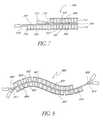
- FIG. 4depicts a TEM flexible in one direction.
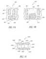
- FIG. 5depicts a TEM flexible in two directions.
- FIG. 6depicts a TEM flexible in multiple directions.
- FIG. 7depicts a flexible TEM with heating and cooling in separate zones of the same substrate.
- FIG. 8depicts a multi-layer flexible substrate.
- FIG. 9depicts representative patterns for flexible conductors in a flexible TEM.
- FIG. 10depicts a TEM with enhanced heat transfer produced by secondary thermally conductive members.
- FIG. 1Adepicts a conventional TEM 100 with substantially rigid first and second substrates 101 , 102 .
- Power supply 103provides current to the TEM 100 .
- FIG. 1Bdepicts details of the TEM's 100 internal circuitry.
- P-type 104 and N-type 105 TEEsalternate and are electrically connected in series through circuits 106 and 107 .
- the circuits 106 and 107are attached to the substrates 101 and 102 , respectively.
- the electronsflow in the direction indicated by arrows 108 . All of the electrons flow from P-type TEEs 104 to a circuit 106 to N-type TEEs 105 on the first substrate 101 side. On the second substrate 102 side, exactly the opposite occurs. Electrons always flow from the N-type TEEs 105 through circuits 107 to P-type TEEs 104 . Under these circumstances, the flow of heat is shown by the arrows, with q c indicating cooling at substrate 101 and q h indicating heating at substrate 102 . The power in is denoted by q in . T c indicates the temperature of the first substrate 101 , and T h indicates the temperature of the second substrate 102 .
- FIG. 2depicts in more detail a typical circuit pattern for the principal components of the TEM of FIG. 1.
- a first upper substrate 201consists of a series of electrically conductive circuits 203 to which are soldered or otherwise uniformly and electrically connected TEEs 204 , 205 , 206 , 207 , 208 and 209 .
- every circuit 203has two TEEs, one N-type and one P-type, attached.
- a corresponding second or lower substrate 202has electrically conductive circuits 203 attached.
- the lower substrate 202also has two electrical wires 210 and 212 electrically attached to two of the circuits 203 , the wires 210 and 212 are shown sheathed in insulation 211 and 213 , respectively.
- the upper substrate 201When assembled, the upper substrate 201 is positioned with respect to the lower substrate 202 so that the two ends of the TEE 204 engage circuits 203 . Similarly, TEEs 205 , 206 , 207 , 208 and 209 ends are engaged as shown.
- Currententers through the wire 210 and passes upward from the lower substrate 202 to the upper substrate 203 through the TEE 205 . It then passes along the circuit 203 to the TEE 206 , and so on, as was illustrated in FIG. 1 .
- This patterncontinues through TEE 208 where the circuit 203 connects to TEE 209 on the lower substrate 202 .
- the currentpasses through 209 to the upper substrate 201 , and along the second set of circuits 203 which are interconnected through TEEs (not shown).
- the currentcontinues to pass through circuits 203 and TEEs until it reaches TEE 204 and circuit 203 . From there the current exits the TEM through wire 212 .
- the upper and lower substrates 201 and 202are constructed of electrical nonconductive materials such as alumina ceramic or the like.
- the substrate materialshave as high a thermal conductivity as possible perpendicular to the plane of FIG. 2 so that heat can be transported through the substrates to the outer faces of the assembled TEM with as little temperature change as possible.
- the circuit material and the circuit 203 designshould maximize electrical conductivity between adjacent TEEs. This combination of design and material properties held minimize thermal and electrical losses in the TEM.
- FIG. 3Adepicts an example of a substrate system 300 wherein at least one of the substrates is constructed of a substantially rigid material in one preferred embodiment.
- the upper substrate 301is made from a high thermal conductivity flexible material preferably such as Kapton polyamide film, very thin fiberglass, or any other flexible material.
- Circuits 303are on the upper substrate in a pattern.
- a lower substrate 302which is preferably, but not necessarily, of a substantially rigid material, has circuits 315 arranged in a pattern on it.
- TEEs 304 , 305 , 306 and 307are some of the TEEs in the TEM.
- Wires 309 and 311each attach to a circuit. Insulation 310 and 312 sheathe the wire.
- the upper circuit 301is connected to the lower circuit 302 so that the respective ends of the TEEs 304 , 305 , 306 and 307 mate at the positions indicated in FIG. 3 A.
- the TEEsare of N-type and P-type and are arrayed with the circuits 303 and 315 so that current flows alternately through each type of material. The pattern is such that current flows from one wire 309 through the TEM 300 to the other wire 311 , as was described in detail in FIG. 2 .
- slotsare cut into the lower substrate at positions 313 so as to separate the lower substrate 302 into segments.
- the upper substrate 301can flex in the areas 308 if the circuits 303 can flex so as to not degrade the TEE circuit 303 electrical connection.
- the TEMcan be flexed in a concave direction with respect to the outer surface of the TEM upper substrate 301 .
- the TEMcan be twisted about its length as well as bent.
- slotsare made in the lower substrate 302 so as to remove material as shown at 313 , the TEM can flex in both directions.
- FIG. 3AThe general description of FIG. 3A holds for an even number of TEEs in a horizontal row. For larger number of TEEs, there will be one circuit 315 for every two TEEs added in each row of the lower substrate 302 . One circuit 317 is added for each circuit 315 added.
- FIG. 3Bdepicts a configuration 320 with an odd number of TEEs (for example, 325 , 326 and 327 ) in each horizontal row.
- both the upper substrate 321 and the lower substrate 322have both horizontal and vertical circuits 323 and 324 .
- the assemblyconsists of N and P-type TEEs, and circuits arranged as described therein. Wire assemblies 333 and 334 are attached at the ends. Cuts 329 and 330 are made respectively in the upper substrate 321 and the lower substrate 322 at the locations shown.
- the TEMWhen the TEM is assembled, for example, current enters through wire assembly 333 and into TEE 325 and so on until it exits at the wire assembly 324 , after passing through the TEE 335 .
- the TEEsare alternately P and N-types so that as current passes, one side is heated and the other cooled.
- the cuts 329 and 330allow the assembled TEM to flex in two directions if the circuits 323 and 324 can flex or bend at 331 and 332 . If the cuts 329 and 330 are formed as slots with the removal of substrate material, the corresponding flexure points can bend in both directions. Finally, if cuts 336 and 337 are incorporated, the assembled TEM can twist about its length.
- TEMs 300 and 320form separate arrays.
- part of a TEMcan be of one type and other parts of the other type.
- FIG. 4depicts a TEM 400 with an upper substrate 401 and cut lower substrate 402 .
- the lower substrate materialis substantially rigid, but is modified or configured in a manner to be flexible. In this configuration, dividing the substrate into sections permits the flexibility.
- Wire assemblies 406 and 407are attached at each end.
- each rowhas an even number of TEEs 405 and 408 .
- the TEEsare connected via circuits (not shown) as in FIG. 3 A.
- the circuitsin practice, generally are very thin, such as printed circuit traces. Therefore, the circuits are often not shown in the Figures herein, except to illustrate the manner in which the circuits connect the individual TEEs.
- the TEMhas been bent in the principal direction indicated in the description of FIG. 3 A. Spaces 403 develop because of the flexure. For descriptive purposes, the lower substrate 402 has not been cut at location 404 and therefore, that segment does not have a bend to it.
- FIG. 5depicts a TEM 500 formed according to FIG. 3 B. It consists of a lower substrate 501 , preferably but not necessarily constructed from substantially rigid material with cuts 505 and 506 to permit flexing and an upper substrate 502 with cuts 503 and 504 . TEEs and electrical paths are connected as discussed in FIGS. 2 and 3B.
- the TEM 500is shown flexed in two directions.
- the cuts 503are spread open and form gaps in the upper substrate 502 where TEM 500 is flexed in one direction while other cuts 504 are not open where TEM 500 is flexed in the opposite direction.
- cuts 505are closed while cuts 506 are open.
- FIG. 6depicts a TEM 600 of the type described in FIG. 3 A.
- Wire assemblies 608 and 609are attached to the lower substrate 601 .
- Upper substrate 602 and TEEs 603are connected with circuits (not shown) as discussed in FIG. 3 A.
- Slots 606are in the upper substrate 602 . Opposite the slots 606 are partial cuts not visible in FIG. 6, but of the type shown as slot 314 of the upper substrate 301 in FIG. 3 A.
- the TEM 600is depicted as twisted about its length so that the upper substrate 602 is vertical at location 607 and horizontal at the opposite end 610 .
- the two adjacent circuits at 604 and the two adjacent circuits at 605act as rigid units since there is no twist in the TEM 600 at these points. Twisting occurs at slots 606 in the upper substrate 602 and the partial slots (not shown) at the corresponding location in lower substrate 601 .
- TEEs 603are connected via a circuit (not shown) that is adjacent to a partial slot in the lower substrate 601 . Current can pass through the TEM 600 via wire assemblies 608 and 609 .
- FIG. 7depicts a TEM 700 with the upper substrate 701 , 703 and 705 and a lower substrate 702 , 704 and 706 , circuits (not shown), and TEEs 712 , 713 , 715 and 716 .
- the upper substrate 701is folded upon itself at fold 708 .
- Grease 707 , solder or other high thermal conductivity materialfills the space between the two segments of the upper substrate 703 and 705 .
- a circuit as described in FIG. 2(not shown), connects TEE 712 to TEE 713 .
- the circuit patternis either that of FIG. 3A or 3 B.
- the TEEs 712 and 713are both of the same type. All other TEEs are alternately N-type and P-type and are connected as described in FIG. 2 .
- the upper substrate surface 703removes the heat generated at the upper substrate surface 705 and cools that surface, so that the lower substrate surface 706 is significantly colder than the portion of the upper substrate surface 701 , not contact with substrate surface 705 .
- a typical TEM cascadeis formed in the region of the contact zone 707 , and a single stage TEM is formed elsewhere.
- design of the TEEs in the regions between substrate surfaces 705 and 706 and also between 702 and 703can be of a form well known to the art.
- FIG. 8depicts another variation of a TEM 800 .
- a backbone substrate 801has circuits on each side preferably of the type of upper substrate 301 of FIG. 3 A.
- the TEM 800has two additional substrates, an upper substrate 802 and a lower substrate 804 . Each has slots 807 formed by removing substrate material.
- Between the upper substrate 802 and the backbone substrate 801are TEEs 803 and between the backbone substrate 801 and the lower substrate 804 are TEEs 805 .
- the TEEs 803 and 805are alternately N-type and P-type and are connected by circuits, as in FIG. 3A (not shown).
- the componentsare electrically connected so that the portion above the insulation layer in the backbone substrate 301 forms one TEM circuit with wire connections 808 and 809 and the portion below forms a separate TEM circuit with wire connections 810 and 811 .
- the TEM 800operates by passing current from, for example, 808 to 809 and a separate current from 810 to 811 .
- the currentflows so that the upper substrate 802 is cooled and hence the upper surface of the backbone substrate 801 is heated. Heat passes through to the lower surface of the backbone substrate 801 , which is the cooled side of the lower portion. The lower substrate 804 is therefore heated.
- the TEM 800is a cascade system.
- the backbone substrate 801could be wider, thermal energy transferred through the added width, and the currents could flow so that the backbone substrate 801 was heated or cooled by both the upper and lower TEMs.
- the upper substrate 802 and the lower substrate 804need not be the same dimensions or exact shape, thus, for example, a portion 812 of the lower substrate 804 need not have a corresponding part of the upper substrate 802 , directly in thermal contact with it.
- the upper substrate 802could be of the type shown in FIG. 3 B and the lower substrate 804 of the type shown in FIG. 3 A.
- the upper substrate 302could have fewer TEEs in each row compared to the lower substrate 804 and the total number of TEEs could differ among rows.
- the electrical connectionscould be modified to pass current from the upper circuits of TEM 800 to the lower circuits so that two of the wires, for example, 809 and 811 , would be eliminated.
- Other connection changescould be made to modify performance at certain locations, or to achieve other purposes.
- FIG. 9depicts a portion of a substrate 900 that consists of flexible substrate material 901 , circuits 902 and 903 , solder mask 904 , TEEs 905 and slot 906 .
- the assemblyincorporates substrate 900 to mechanically connect parts.
- circuit 902is of the form previously discussed in FIGS. 3A and 3B.
- Circuit 903depicts a method for allowing that circuit to flex in the region between TEEs 905 .
- solder mask 904covers a portion of the circuit 903 so as to prevent solder from accumulating where it is so covered. If the substrate 901 is flexed, bending will occur preferentially in the solder mask 904 region, since the circuit 903 does not have solder build up there and hence, is thinnest and most easily flexed there. Such preferential bending reduces mechanical stress at the interface of the TEE 905 and circuit 903 .
- FIG. 9Bdepicts another geometry 920 which achieves flexure.
- Flexible substrate material 921has circuits 922 and 923 attached, TEEs 924 and an elongated slot 926 . Sections 925 of the circuit 923 have been omitted.
- the geometry 920is known to the flexible circuit industry as a design that allows severe or repeated flexure with good stability. Further, by proper design, known to the art, solder accumulation in the flexure can be either prevented or reduced to acceptable levels and shear stresses induced during flexure (at the circuit 923 and substrate 921 interface) can be reduced.
- electrically conductive flexuressuch as circuits that incorporate components not attached to the substrate (e.g., shunt wires and strips, electrically conductive hinges, and the like) can be employed to allow needed movement and are the subject of this invention.
- FIG. 10depicts a portion 1000 of a TEM of the present invention. It consists of an upper substrate 1001 with circuits 1002 and upper thermal conductors 1003 attached. A lower substrate 1005 has circuit 1006 and thermal conductor 1007 attached. TEEs 1004 are electrically connected to the circuits. Slots or cuts 1008 are in the upper substrate 1001 to allow flexure.
- the thermal conductors 1003 and 1007are designed to increase and distribute heat flow to and from the TEM.
- the conductors 1003 and 1007are useful in high-power TEMs since typical substrate materials have relatively low thermal conductivity, and thereby reduce TEM performance.
- Performancecan be improved by utilizing thermal conductors to increase thermal energy transport across the substrate and also mechanically strengthen the TEM. These improvements can be done by (1) maximizing the surface area of the circuit substrate and thermal conductor interface, (2) minimizing thermal resistance across the interfaces by selecting materials or material composites that minimize interfacial thermal resistance, or (3) utilizing the thermal conductors as structural members so that the substrate can be thinner, weaker or otherwise allow selection from a broader class of electrical insulators.
- Theseprovide examples of designs that achieve enhanced performance, cost reduction, improved durability, size reduction and other benefits by utilizing additional componentry with the substrate. The above are presented as examples, and they do not cover all variations or otherwise restrict the scope of the invention.
- the substratecould have cuts, slots and sections removed to achieve flexure and bending.
- the same effectcan be achieved by utilizing substrates that are mechanically weak.
- the substratecould be made of a soft or weak material such as Teflon TFE, a silicone rubber, or the like; it could be made very thin; it could be mechanically weakened by incorporating holes, porosity, and making it from felt or the like; could be chemically weakened, treated to have its flexibility increased in selected areas, etched or the like; it could be fabricated with areas weakened, omitted, treated or otherwise modified, made thinner, slotted or the like that frees adjacent TEEs to move toward or away from one another so as to allow flexure and/or twisting within the TEM.
- the substratecould be completely omitted from the TEM so that unconstrained circuits would connect TEEs.
- the circuitsUpon installation (and after flexure), the circuits could be attached to a structural material wherein the bonding agent or the structural material serves the function of a substrate within the system.
Landscapes
- Structure Of Printed Boards (AREA)
Abstract
Description
Claims (57)
Priority Applications (1)
| Application Number | Priority Date | Filing Date | Title |
|---|---|---|---|
| US09/987,804US6700052B2 (en) | 2001-11-05 | 2001-11-05 | Flexible thermoelectric circuit |
Applications Claiming Priority (1)
| Application Number | Priority Date | Filing Date | Title |
|---|---|---|---|
| US09/987,804US6700052B2 (en) | 2001-11-05 | 2001-11-05 | Flexible thermoelectric circuit |
Publications (2)
| Publication Number | Publication Date |
|---|---|
| US20030084935A1 US20030084935A1 (en) | 2003-05-08 |
| US6700052B2true US6700052B2 (en) | 2004-03-02 |
Family
ID=25533582
Family Applications (1)
| Application Number | Title | Priority Date | Filing Date |
|---|---|---|---|
| US09/987,804Expired - LifetimeUS6700052B2 (en) | 2001-11-05 | 2001-11-05 | Flexible thermoelectric circuit |
Country Status (1)
| Country | Link |
|---|---|
| US (1) | US6700052B2 (en) |
Cited By (120)
| Publication number | Priority date | Publication date | Assignee | Title |
|---|---|---|---|---|
| US20040107704A1 (en)* | 2002-07-11 | 2004-06-10 | Hudson Douglas E. | Workpiece chuck with temperature control assembly having spacers between layers providing clearance for thermoelectric modules |
| US20050150537A1 (en)* | 2004-01-13 | 2005-07-14 | Nanocoolers Inc. | Thermoelectric devices |
| US20050150536A1 (en)* | 2004-01-13 | 2005-07-14 | Nanocoolers, Inc. | Method for forming a monolithic thin-film thermoelectric device including complementary thermoelectric materials |
| US20050150539A1 (en)* | 2004-01-13 | 2005-07-14 | Nanocoolers, Inc. | Monolithic thin-film thermoelectric device including complementary thermoelectric materials |
| US20050160752A1 (en)* | 2004-01-23 | 2005-07-28 | Nanocoolers, Inc. | Apparatus and methodology for cooling of high power density devices by electrically conducting fluids |
| US20050172994A1 (en)* | 2002-11-12 | 2005-08-11 | Naoki Shutoh | Thermoelectric material and thermoelectric element |
| US20050264086A1 (en)* | 2004-05-25 | 2005-12-01 | John Lofy | Climate controlled seat |
| US20060076046A1 (en)* | 2004-10-08 | 2006-04-13 | Nanocoolers, Inc. | Thermoelectric device structure and apparatus incorporating same |
| US20060087160A1 (en)* | 2004-10-25 | 2006-04-27 | Hanh Dong | Apparatus for providing fluid through a vehicle seat |
| US20060105620A1 (en)* | 2004-11-17 | 2006-05-18 | Julio Navarro | Forming and bonding of flex circuits to structures |
| US20060102032A1 (en)* | 2004-10-29 | 2006-05-18 | Peow Ng | Heating system for printing apparatus |
| US20060130490A1 (en)* | 2004-12-20 | 2006-06-22 | Dusko Petrovski | Control system for thermal module vehicle |
| US20060137359A1 (en)* | 2004-12-23 | 2006-06-29 | Nanocoolers, Inc. | Counterflow thermoelectric configuration employing thermal transfer fluid in closed cycle |
| US20060137360A1 (en)* | 2004-12-23 | 2006-06-29 | Nanocoolers, Inc. | Thermoelectric configuration employing thermal transfer fluid flow(s) with recuperator |
| US20060175877A1 (en)* | 2005-02-07 | 2006-08-10 | L&P Property Management Company | Heat, cool, and ventilate system for automotive applications |
| US20060180583A1 (en)* | 2005-02-03 | 2006-08-17 | W.E.T. Automotive Group Ag | Glasses temperature regulation device |
| US20060214480A1 (en)* | 2005-03-23 | 2006-09-28 | John Terech | Vehicle seat with thermal elements |
| US20060273646A1 (en)* | 2005-05-16 | 2006-12-07 | Brian Comiskey | Ventilated headrest |
| US20070035448A1 (en)* | 2005-08-09 | 2007-02-15 | Navarro Julio A | Compliant, internally cooled antenna apparatus and method |
| US20070158981A1 (en)* | 2005-11-10 | 2007-07-12 | W.E.T. Automotive Systems, Ag | Vehicle seat with cushioning layer |
| US20070200398A1 (en)* | 2006-02-28 | 2007-08-30 | Scott Richard Wolas | Climate controlled seat |
| US20070241592A1 (en)* | 2006-04-13 | 2007-10-18 | Griffin Steven C | Tie strap for climate controlled seat |
| US20070262621A1 (en)* | 2004-10-25 | 2007-11-15 | Hanh Dong | Apparatus for providing fluid through a vehicle seat |
| US20080047598A1 (en)* | 2006-08-03 | 2008-02-28 | Amerigon Inc. | Thermoelectric device |
| US20080100101A1 (en)* | 2006-11-01 | 2008-05-01 | Amerigon Inc. | Chair with air conditioning device |
| US20080099701A1 (en)* | 2006-08-22 | 2008-05-01 | Cameron International Corporation | Fluid Saving Blowout Preventer Operator System |
| US20080148481A1 (en)* | 2006-10-13 | 2008-06-26 | Amerigon Inc. | Air conditioned bed |
| US20080160900A1 (en)* | 2003-09-25 | 2008-07-03 | W.E.T. Automotive Systems Ag | Method for ventilating a seat |
| US20090000309A1 (en)* | 2007-06-29 | 2009-01-01 | Jeffrey Gerard Hershberger | Flexible assemblies with integrated thermoelectric modules suitable for use in extracting power from or dissipating heat from fluid conduits |
| US7475551B2 (en) | 2004-12-23 | 2009-01-13 | Nanocoolers, Inc. | System employing temporal integration of thermoelectric action |
| US20090014046A1 (en)* | 2007-07-12 | 2009-01-15 | Industrial Technology Research Institute | Flexible thermoelectric device and manufacturing method thereof |
| US20090026813A1 (en)* | 2007-07-23 | 2009-01-29 | John Lofy | Radial thermoelectric device assembly |
| US20090025770A1 (en)* | 2007-07-23 | 2009-01-29 | John Lofy | Segmented thermoelectric device |
| US20090033130A1 (en)* | 2007-07-02 | 2009-02-05 | David Marquette | Fluid delivery systems for climate controlled seats |
| US20090218855A1 (en)* | 2008-02-26 | 2009-09-03 | Amerigon Incorporated | Climate control systems and devices for a seating assembly |
| US7588288B2 (en) | 2003-10-17 | 2009-09-15 | W.E.T. Automotive Systems Ag | Automotive vehicle seat insert |
| US20090293499A1 (en)* | 2008-06-03 | 2009-12-03 | Bell Lon E | Thermoelectric heat pump |
| US7640754B2 (en) | 2006-12-14 | 2010-01-05 | Amerigon Incorporated | Insert duct piece for thermal electric module |
| US20100011502A1 (en)* | 2008-07-18 | 2010-01-21 | Amerigon Incorporated | Climate controlled bed assembly |
| US20100052374A1 (en)* | 2007-05-25 | 2010-03-04 | Bsst Llc | System and method for climate control within a passenger compartment of a vehicle |
| US7708338B2 (en) | 2006-10-10 | 2010-05-04 | Amerigon Incorporated | Ventilation system for seat |
| US20100141753A1 (en)* | 2000-05-03 | 2010-06-10 | Aperio Technologies, Inc. | Optimizing Virtual Slide Image Quality |
| US20100193498A1 (en)* | 2009-01-28 | 2010-08-05 | Amerigon Incorporated | Convective heater |
| US20100199687A1 (en)* | 2009-02-11 | 2010-08-12 | Marlow Industries, Inc. | Temperature control device |
| US20100209230A1 (en)* | 2009-02-18 | 2010-08-19 | W.E.T. Automotive Systems Ag | Air conditioning device for vehicle seats |
| US7827805B2 (en) | 2005-03-23 | 2010-11-09 | Amerigon Incorporated | Seat climate control system |
| US20110011098A1 (en)* | 2009-07-15 | 2011-01-20 | Hon Hai Precision Industry Co., Ltd. | Heat recycling system |
| US20110016888A1 (en)* | 2009-07-24 | 2011-01-27 | Basf Se | Thermoelectric module |
| US7877827B2 (en) | 2007-09-10 | 2011-02-01 | Amerigon Incorporated | Operational control schemes for ventilated seat or bed assemblies |
| US20110030754A1 (en)* | 2009-08-06 | 2011-02-10 | Laird Technologies, Inc. | Thermoelectric modules and related methods |
| US20110099991A1 (en)* | 2009-11-03 | 2011-05-05 | Basf Se | Use of porous metallic materials as contact connection in thermoelectric modules |
| US20110115635A1 (en)* | 2009-05-06 | 2011-05-19 | Dusko Petrovski | Control schemes and features for climate-controlled beds |
| US20110174350A1 (en)* | 2010-01-19 | 2011-07-21 | Alexander Gurevich | Thermoelectric generator |
| US8143554B2 (en) | 2007-03-16 | 2012-03-27 | Amerigon Incorporated | Air warmer |
| US8191187B2 (en) | 2009-08-31 | 2012-06-05 | Amerigon Incorporated | Environmentally-conditioned topper member for beds |
| US8256236B2 (en) | 2008-02-01 | 2012-09-04 | Gentherm Incorporated | Condensation and humidity sensors for thermoelectric devices |
| US20130104951A1 (en)* | 2010-05-05 | 2013-05-02 | Guillaume Savelli | Optimized thermoelectric module for operation in peltier mode or in seebeck mode |
| US8438863B2 (en) | 2006-01-30 | 2013-05-14 | Gentherm Incorporated | Climate controlled beverage container |
| USRE44272E1 (en) | 1998-05-12 | 2013-06-11 | Gentherm Incorporated | Thermoelectric heat exchanger |
| US8495884B2 (en) | 2001-02-09 | 2013-07-30 | Bsst, Llc | Thermoelectric power generating systems utilizing segmented thermoelectric elements |
| US8503941B2 (en) | 2008-02-21 | 2013-08-06 | The Boeing Company | System and method for optimized unmanned vehicle communication using telemetry |
| WO2013115445A1 (en)* | 2012-01-30 | 2013-08-08 | 연세대학교 산학협력단 | Thermoelectric element having structure capable of improving thermal efficiency |
| US8539624B2 (en) | 2006-05-31 | 2013-09-24 | Gentherm Incorporated | Structure based fluid distribution system |
| DE102012105743A1 (en)* | 2012-06-29 | 2014-01-02 | Elringklinger Ag | Heat shielding device with thermoelectric energy use |
| US8649179B2 (en) | 2011-02-05 | 2014-02-11 | Laird Technologies, Inc. | Circuit assemblies including thermoelectric modules |
| US20140102501A1 (en)* | 2011-06-09 | 2014-04-17 | Tohoku University | Thermoelectric conversion apparatus |
| US8722222B2 (en) | 2011-07-11 | 2014-05-13 | Gentherm Incorporated | Thermoelectric-based thermal management of electrical devices |
| US8915091B2 (en) | 2005-04-08 | 2014-12-23 | Gentherm Incorporated | Thermoelectric-based thermal management system |
| US9006557B2 (en) | 2011-06-06 | 2015-04-14 | Gentherm Incorporated | Systems and methods for reducing current and increasing voltage in thermoelectric systems |
| US20150153237A1 (en)* | 2012-09-19 | 2015-06-04 | Fujitsu Limited | Power generation device, measurement device, and measurement system |
| US9105808B2 (en) | 2007-01-10 | 2015-08-11 | Gentherm Incorporated | Thermoelectric device |
| US9103573B2 (en) | 2006-08-02 | 2015-08-11 | Gentherm Incorporated | HVAC system for a vehicle |
| US9121414B2 (en) | 2010-11-05 | 2015-09-01 | Gentherm Incorporated | Low-profile blowers and methods |
| US9125497B2 (en) | 2007-10-15 | 2015-09-08 | Gentherm Incorporated | Climate controlled bed assembly with intermediate layer |
| US9131781B2 (en) | 2012-12-27 | 2015-09-15 | Select Comfort Corporation | Distribution pad for a temperature control system |
| WO2015157161A1 (en)* | 2014-04-07 | 2015-10-15 | Alphabet Energy, Inc. | Flexible lead frame for multi-leg package assembly |
| US9162769B2 (en) | 2010-04-06 | 2015-10-20 | Gentherm Gmbh | Occupancy sensor that measures electric current through a heating element |
| US9172023B2 (en) | 2007-08-24 | 2015-10-27 | Gentherm Gmbh | Electrothermal transducer, and temperature controlling device |
| US9257627B2 (en) | 2012-07-23 | 2016-02-09 | Alphabet Energy, Inc. | Method and structure for thermoelectric unicouple assembly |
| US9293680B2 (en) | 2011-06-06 | 2016-03-22 | Gentherm Incorporated | Cartridge-based thermoelectric systems |
| US9306143B2 (en) | 2012-08-01 | 2016-04-05 | Gentherm Incorporated | High efficiency thermoelectric generation |
| US9318682B2 (en) | 2012-01-25 | 2016-04-19 | Alphabet Energy, Inc | Modular thermoelectric units for heat recovery systems and methods thereof |
| US20160129817A1 (en)* | 2013-06-04 | 2016-05-12 | Denso Corporation | Comfortable temperature control apparatus using heat flux sensor |
| WO2016089707A1 (en)* | 2014-12-03 | 2016-06-09 | Thermogen Technologies, Inc. | Flexible thermoelectric generator |
| US9365090B2 (en) | 2004-05-10 | 2016-06-14 | Gentherm Incorporated | Climate control system for vehicles using thermoelectric devices |
| US9445524B2 (en) | 2012-07-06 | 2016-09-13 | Gentherm Incorporated | Systems and methods for thermoelectrically cooling inductive charging stations |
| US9440567B2 (en) | 2005-08-19 | 2016-09-13 | Gentherm Gmbh | Automotive vehicle seat insert |
| US9448017B2 (en) | 2011-12-09 | 2016-09-20 | Gentherm Gmbh | Temperature control system for an electrochemical voltage source |
| US9447994B2 (en) | 2008-10-23 | 2016-09-20 | Gentherm Incorporated | Temperature control systems with thermoelectric devices |
| DE102015105939A1 (en) | 2015-04-17 | 2016-10-20 | Elringklinger Ag | Device for the thermoelectric conversion of thermal energy |
| US9555686B2 (en) | 2008-10-23 | 2017-01-31 | Gentherm Incorporated | Temperature control systems with thermoelectric devices |
| US9596945B2 (en) | 2014-04-16 | 2017-03-21 | Tempur-Pedic Management, Llc | Support cushions and methods for dissipating heat away from the same |
| US9608188B2 (en) | 2013-09-01 | 2017-03-28 | Alphabet Energy, Inc. | Thermoelectric devices having reduced thermal stress and contact resistance, and methods of forming and using the same |
| US20170144574A1 (en)* | 2014-06-03 | 2017-05-25 | Denso Corporation | Temperature adjustment control device |
| US9666914B2 (en) | 2009-05-18 | 2017-05-30 | Gentherm Incorporated | Thermoelectric-based battery thermal management system |
| US9662962B2 (en) | 2013-11-05 | 2017-05-30 | Gentherm Incorporated | Vehicle headliner assembly for zonal comfort |
| US9685599B2 (en) | 2011-10-07 | 2017-06-20 | Gentherm Incorporated | Method and system for controlling an operation of a thermoelectric device |
| US20170229629A1 (en)* | 2016-02-10 | 2017-08-10 | The Boeing Company | System for recapturing energy lost to plasma or ionization heating |
| US20170325359A1 (en)* | 2016-05-09 | 2017-11-09 | Nathan S. Lazarus | Self cooling stretchable electrical circuit having a conduit forming an electrical component and containing electrically conductive liquid |
| US9857107B2 (en) | 2006-10-12 | 2018-01-02 | Gentherm Incorporated | Thermoelectric device with internal sensor |
| US9865794B2 (en) | 2011-11-17 | 2018-01-09 | Gentherm Incorporated | Thermoelectric devices with interface materials and methods of manufacturing the same |
| US9989267B2 (en) | 2012-02-10 | 2018-06-05 | Gentherm Incorporated | Moisture abatement in heating operation of climate controlled systems |
| US10106011B2 (en) | 2009-05-18 | 2018-10-23 | Gentherm Incorporated | Temperature control system with thermoelectric device |
| US10160356B2 (en) | 2014-05-09 | 2018-12-25 | Gentherm Incorporated | Climate control assembly |
| US10219323B2 (en) | 2014-02-14 | 2019-02-26 | Genthrem Incorporated | Conductive convective climate controlled seat |
| US10270141B2 (en) | 2013-01-30 | 2019-04-23 | Gentherm Incorporated | Thermoelectric-based thermal management system |
| US10439122B2 (en)* | 2016-04-15 | 2019-10-08 | Hyundai Motor Company | Thermoelectric module |
| US10589647B2 (en) | 2013-12-05 | 2020-03-17 | Gentherm Incorporated | Systems and methods for climate controlled seats |
| US10827845B2 (en) | 2017-02-24 | 2020-11-10 | Sealy Technology, Llc | Support cushions including a support insert with a bag for directing air flow, and methods for controlling surface temperature of same |
| US10991869B2 (en) | 2018-07-30 | 2021-04-27 | Gentherm Incorporated | Thermoelectric device having a plurality of sealing materials |
| US11033058B2 (en) | 2014-11-14 | 2021-06-15 | Gentherm Incorporated | Heating and cooling technologies |
| US11152557B2 (en) | 2019-02-20 | 2021-10-19 | Gentherm Incorporated | Thermoelectric module with integrated printed circuit board |
| US11152556B2 (en) | 2017-07-29 | 2021-10-19 | Nanohmics, Inc. | Flexible and conformable thermoelectric compositions |
| US11160386B2 (en) | 2018-06-29 | 2021-11-02 | Tempur World, Llc | Body support cushion with ventilation system |
| US11375825B2 (en) | 2018-02-22 | 2022-07-05 | Sealy Technology, Llc | Support cushions including a pocketed coil layer with a plurality of fabric types for directing air flow, and methods for controlling surface temperature of same |
| US11571999B2 (en)* | 2019-12-02 | 2023-02-07 | Hyundai Motor Company | System and method for adjusting properties of seat for vehicles |
| US11639816B2 (en) | 2014-11-14 | 2023-05-02 | Gentherm Incorporated | Heating and cooling technologies including temperature regulating pad wrap and technologies with liquid system |
| US11857004B2 (en) | 2014-11-14 | 2024-01-02 | Gentherm Incorporated | Heating and cooling technologies |
| US11993132B2 (en) | 2018-11-30 | 2024-05-28 | Gentherm Incorporated | Thermoelectric conditioning system and methods |
| US12442569B2 (en)* | 2024-04-01 | 2025-10-14 | Nouvel Technologies, Inc. | Energy recovery from waste heat |
Families Citing this family (41)
| Publication number | Priority date | Publication date | Assignee | Title |
|---|---|---|---|---|
| US6893086B2 (en) | 2002-07-03 | 2005-05-17 | W.E.T. Automotive Systems Ltd. | Automotive vehicle seat insert |
| US6857697B2 (en) | 2002-08-29 | 2005-02-22 | W.E.T. Automotive Systems Ag | Automotive vehicle seating comfort system |
| DE10259648B4 (en) | 2002-12-18 | 2006-01-26 | W.E.T. Automotive Systems Ag | Air-conditioned seat and air conditioning device for a ventilated seat |
| DE10259621B4 (en) | 2002-12-18 | 2005-12-01 | W.E.T. Automotive Systems Ag | Vehicle seat and associated air conditioning device |
| US7274007B2 (en) | 2003-09-25 | 2007-09-25 | W.E.T. Automotive Systems Ltd. | Control system for operating automotive vehicle components |
| JP2005116746A (en)* | 2003-10-07 | 2005-04-28 | Toshiba Corp | Thermoelectric conversion material and thermoelectric conversion element using the same |
| US7425034B2 (en) | 2003-10-17 | 2008-09-16 | W.E.T. Automotive Systems Ag | Automotive vehicle seat having a comfort system |
| US7461892B2 (en) | 2003-12-01 | 2008-12-09 | W.E.T. Automotive Systems, A.C. | Valve layer for a seat |
| JP4468044B2 (en)* | 2004-03-30 | 2010-05-26 | 株式会社東芝 | Thermoelectric material and thermoelectric conversion element |
| JP4239010B2 (en)* | 2004-08-18 | 2009-03-18 | 独立行政法人産業技術総合研究所 | Composite oxide having p-type thermoelectric conversion characteristics |
| US7763792B2 (en)* | 2005-02-14 | 2010-07-27 | Marlow Industries, Inc. | Multistage heat pumps and method of manufacture |
| DE102005018445B3 (en) | 2005-04-20 | 2006-06-29 | W.E.T. Automotive Systems Ag | Air conditioning device for e.g. vehicle seat has air-conditioning zones, which are connected to recess by connecting device whereby recess allows the air to pass through it partially in transverse direction inspite of cover |
| US7870745B2 (en)* | 2006-03-16 | 2011-01-18 | Bsst Llc | Thermoelectric device efficiency enhancement using dynamic feedback |
| US7779639B2 (en)* | 2006-08-02 | 2010-08-24 | Bsst Llc | HVAC system for hybrid vehicles using thermoelectric devices |
| US9373770B2 (en)* | 2006-09-28 | 2016-06-21 | Rosemount Inc. | Industrial thermoelectric generator |
| FR2919431B1 (en)* | 2007-07-23 | 2010-08-27 | Commissariat Energie Atomique | THERMOELECTRIC MEDIUM AND FABRIC TYPE STRUCTURE INTEGRATING SUCH A MEANS. |
| CN102239579A (en)* | 2008-08-01 | 2011-11-09 | Bsst有限责任公司 | Enhanced thermally isolated thermoelectrics |
| WO2010048575A1 (en)* | 2008-10-23 | 2010-04-29 | Bsst Llc | Multi-mode hvac system with thermoelectric device |
| DE202009017050U1 (en) | 2008-12-21 | 2010-05-12 | W.E.T. Automotive Systems Ag | aerator |
| JP2012517016A (en)* | 2009-02-04 | 2012-07-26 | ネーデルランドセ・オルガニサティ・フォール・トゥーヘパスト−ナトゥールウェテンスハッペライク・オンデルズーク・テーエヌオー | Origami sensor |
| DE112010004107A5 (en)* | 2009-10-23 | 2012-10-25 | Miba Sinter Austria Gmbh | THERMO GENERATOR |
| DE102009046099A1 (en)* | 2009-10-28 | 2011-05-05 | Robert Bosch Gmbh | Method for producing a sea shelf module and corresponding sea shelf module |
| WO2011116303A1 (en) | 2010-03-19 | 2011-09-22 | Micropen Technologies Corporation | Thermocouple device |
| CN101894903B (en)* | 2010-06-25 | 2012-03-28 | 清华大学 | photoelectric conversion device |
| US8969703B2 (en) | 2010-09-13 | 2015-03-03 | Tempronics, Inc. | Distributed thermoelectric string and insulating panel |
| US9048004B2 (en) | 2010-12-20 | 2015-06-02 | Gmz Energy, Inc. | Half-heusler alloys with enhanced figure of merit and methods of making |
| KR20140045408A (en) | 2011-07-06 | 2014-04-16 | 템프로닉스, 인크. | Integration of distributed thermoelectric heating and cooling |
| US9638442B2 (en) | 2012-08-07 | 2017-05-02 | Tempronics, Inc. | Medical, topper, pet wireless, and automated manufacturing of distributed thermoelectric heating and cooling |
| US9676310B2 (en) | 2012-09-25 | 2017-06-13 | Faurecia Automotive Seating, Llc | Vehicle seat with thermal device |
| WO2014135600A1 (en)* | 2013-03-06 | 2014-09-12 | O-Flexx Technologies Gmbh | Carrier element and module |
| CN105848964B (en) | 2013-11-04 | 2020-01-03 | 坦普罗尼克斯公司 | Design of thermoelectric strings, plates and envelopes for function and durability |
| US9929332B2 (en)* | 2014-04-25 | 2018-03-27 | North Carolina State University | Flexible thermoelectric devices, methods of preparation thereof, and methods of recovering waste heat therewith |
| US20160197260A1 (en)* | 2015-01-05 | 2016-07-07 | The Boeing Company | Thermoelectric generator |
| WO2016130840A1 (en)* | 2015-02-12 | 2016-08-18 | Tempronics, Inc. | Distributed thermoelectric module with flexible dimensions |
| KR101704257B1 (en) | 2015-09-10 | 2017-02-07 | 현대자동차주식회사 | Thermoelectric module |
| CN113270536A (en)* | 2016-10-31 | 2021-08-17 | 泰格韦有限公司 | Flexible thermoelectric module and thermoelectric device comprising same |
| WO2019245474A2 (en)* | 2017-08-08 | 2019-12-26 | Tes Termoelektrik Sistemleri Ltd. | Thermoelectric vehicle liquid cooler |
| EP3732737A4 (en)* | 2017-12-27 | 2022-01-19 | 3M Innovative Properties Company | Flexible thermoelectric device |
| CN108305935A (en)* | 2018-02-08 | 2018-07-20 | 南方科技大学 | Flexible thermoelectric device and preparation method thereof |
| KR102564026B1 (en)* | 2019-05-07 | 2023-08-07 | 현대자동차주식회사 | Thermoelectric module |
| DE102019207496A1 (en)* | 2019-05-22 | 2020-11-26 | Mahle International Gmbh | Thermoelectric module |
Citations (17)
| Publication number | Priority date | Publication date | Assignee | Title |
|---|---|---|---|---|
| US3554815A (en)* | 1963-04-30 | 1971-01-12 | Du Pont | Thin,flexible thermoelectric device |
| US3635037A (en) | 1969-09-02 | 1972-01-18 | Buderus Eisenwerk | Peltier-effect heat pump |
| US3681929A (en) | 1969-12-10 | 1972-08-08 | Hans Schering | Thermoelectric device |
| US3779814A (en) | 1972-12-26 | 1973-12-18 | Monsanto Co | Thermoelectric devices utilizing electrically conducting organic salts |
| US4065936A (en) | 1976-06-16 | 1978-01-03 | Borg-Warner Corporation | Counter-flow thermoelectric heat pump with discrete sections |
| US4730459A (en) | 1984-09-12 | 1988-03-15 | Air Industrie | Thermoelectric modules, used in thermoelectric apparatus and in thermoelectric devices using such thermoelectric modules |
| US5092129A (en) | 1989-03-20 | 1992-03-03 | United Technologies Corporation | Space suit cooling apparatus |
| US5228923A (en) | 1991-12-13 | 1993-07-20 | Implemed, Inc. | Cylindrical thermoelectric cells |
| US5232516A (en) | 1991-06-04 | 1993-08-03 | Implemed, Inc. | Thermoelectric device with recuperative heat exchangers |
| US5802856A (en) | 1996-07-31 | 1998-09-08 | Stanford University | Multizone bake/chill thermal cycling module |
| US6084172A (en) | 1997-03-27 | 2000-07-04 | Seiko Instruments R&D Center Inc. | Thermoelectric conversion component |
| US6097088A (en)* | 1995-09-29 | 2000-08-01 | Morix Co., Ltd. | Thermoelectric element and cooling or heating device provided with the same |
| US6334311B1 (en) | 1999-03-05 | 2002-01-01 | Samsung Electronics Co., Ltd. | Thermoelectric-cooling temperature control apparatus for semiconductor device fabrication facility |
| US6346668B1 (en) | 1999-10-13 | 2002-02-12 | Mcgrew Stephen P. | Miniature, thin-film, solid state cryogenic cooler |
| WO2002013282A1 (en)* | 2000-08-09 | 2002-02-14 | Peltech S.R.L. | Thermoelectric heat pump |
| US6347521B1 (en) | 1999-10-13 | 2002-02-19 | Komatsu Ltd | Temperature control device and method for manufacturing the same |
| US6410971B1 (en)* | 2001-07-12 | 2002-06-25 | Ferrotec (Usa) Corporation | Thermoelectric module with thin film substrates |
- 2001
- 2001-11-05USUS09/987,804patent/US6700052B2/ennot_activeExpired - Lifetime
Patent Citations (17)
| Publication number | Priority date | Publication date | Assignee | Title |
|---|---|---|---|---|
| US3554815A (en)* | 1963-04-30 | 1971-01-12 | Du Pont | Thin,flexible thermoelectric device |
| US3635037A (en) | 1969-09-02 | 1972-01-18 | Buderus Eisenwerk | Peltier-effect heat pump |
| US3681929A (en) | 1969-12-10 | 1972-08-08 | Hans Schering | Thermoelectric device |
| US3779814A (en) | 1972-12-26 | 1973-12-18 | Monsanto Co | Thermoelectric devices utilizing electrically conducting organic salts |
| US4065936A (en) | 1976-06-16 | 1978-01-03 | Borg-Warner Corporation | Counter-flow thermoelectric heat pump with discrete sections |
| US4730459A (en) | 1984-09-12 | 1988-03-15 | Air Industrie | Thermoelectric modules, used in thermoelectric apparatus and in thermoelectric devices using such thermoelectric modules |
| US5092129A (en) | 1989-03-20 | 1992-03-03 | United Technologies Corporation | Space suit cooling apparatus |
| US5232516A (en) | 1991-06-04 | 1993-08-03 | Implemed, Inc. | Thermoelectric device with recuperative heat exchangers |
| US5228923A (en) | 1991-12-13 | 1993-07-20 | Implemed, Inc. | Cylindrical thermoelectric cells |
| US6097088A (en)* | 1995-09-29 | 2000-08-01 | Morix Co., Ltd. | Thermoelectric element and cooling or heating device provided with the same |
| US5802856A (en) | 1996-07-31 | 1998-09-08 | Stanford University | Multizone bake/chill thermal cycling module |
| US6084172A (en) | 1997-03-27 | 2000-07-04 | Seiko Instruments R&D Center Inc. | Thermoelectric conversion component |
| US6334311B1 (en) | 1999-03-05 | 2002-01-01 | Samsung Electronics Co., Ltd. | Thermoelectric-cooling temperature control apparatus for semiconductor device fabrication facility |
| US6346668B1 (en) | 1999-10-13 | 2002-02-12 | Mcgrew Stephen P. | Miniature, thin-film, solid state cryogenic cooler |
| US6347521B1 (en) | 1999-10-13 | 2002-02-19 | Komatsu Ltd | Temperature control device and method for manufacturing the same |
| WO2002013282A1 (en)* | 2000-08-09 | 2002-02-14 | Peltech S.R.L. | Thermoelectric heat pump |
| US6410971B1 (en)* | 2001-07-12 | 2002-06-25 | Ferrotec (Usa) Corporation | Thermoelectric module with thin film substrates |
Non-Patent Citations (7)
| Title |
|---|
| A New Concept for Improving Thermoelectric Heat Pump Efficiency, R.J. Buist, J.W. Fenton and J.S. Lee, Borg-Warner Thermoelectrics Wolf and Algonquin Road. |
| A New Concept of Porous Thermoelectric Module Using a Reciprocating Flow for Cooling/Heating System (Numerical Analysis for Heating System), Shigeru Tada, Ryozo Echigo and Hideo Yoshida, 16<th >International Conference on Thermoelectrics (1997). |
| A New Concept of Porous Thermoelectric Module Using a Reciprocating Flow for Cooling/Heating System (Numerical Analysis for Heating System), Shigeru Tada, Ryozo Echigo and Hideo Yoshida, 16th International Conference on Thermoelectrics (1997). |
| H. J. Goldsmid, Electronic Refrigeration, Pion Ltd, 207 Brondesbury Park, London (1986). |
| International Search Report for PCT/US 02/03654 dated Jun. 12, 2002. |
| International Search Report for PCT/US 02/06285 dated Jun. 12, 2002. |
| Stanley W. Angrist, Direct Energy Conversion, 32 Ed. Ally & Bacon (1976). |
Cited By (231)
| Publication number | Priority date | Publication date | Assignee | Title |
|---|---|---|---|---|
| USRE44272E1 (en) | 1998-05-12 | 2013-06-11 | Gentherm Incorporated | Thermoelectric heat exchanger |
| US20100141753A1 (en)* | 2000-05-03 | 2010-06-10 | Aperio Technologies, Inc. | Optimizing Virtual Slide Image Quality |
| US8495884B2 (en) | 2001-02-09 | 2013-07-30 | Bsst, Llc | Thermoelectric power generating systems utilizing segmented thermoelectric elements |
| US6886347B2 (en)* | 2002-07-11 | 2005-05-03 | Temptronic Corporation | Workpiece chuck with temperature control assembly having spacers between layers providing clearance for thermoelectric modules |
| US20040107704A1 (en)* | 2002-07-11 | 2004-06-10 | Hudson Douglas E. | Workpiece chuck with temperature control assembly having spacers between layers providing clearance for thermoelectric modules |
| US8637758B2 (en)* | 2002-11-12 | 2014-01-28 | Kabushiki Kaisha Toshiba | Thermoelectric material and thermoelectric element |
| US20050172994A1 (en)* | 2002-11-12 | 2005-08-11 | Naoki Shutoh | Thermoelectric material and thermoelectric element |
| US8067686B2 (en)* | 2002-11-12 | 2011-11-29 | Kabushiki Kaisha Toshiba | Thermoelectric material and thermoelectric element |
| US20120037199A1 (en)* | 2002-11-12 | 2012-02-16 | Naoki Shutoh | Thermoelectric material and thermoelectric element |
| US20080160900A1 (en)* | 2003-09-25 | 2008-07-03 | W.E.T. Automotive Systems Ag | Method for ventilating a seat |
| US7588288B2 (en) | 2003-10-17 | 2009-09-15 | W.E.T. Automotive Systems Ag | Automotive vehicle seat insert |
| US20050150539A1 (en)* | 2004-01-13 | 2005-07-14 | Nanocoolers, Inc. | Monolithic thin-film thermoelectric device including complementary thermoelectric materials |
| US20050150536A1 (en)* | 2004-01-13 | 2005-07-14 | Nanocoolers, Inc. | Method for forming a monolithic thin-film thermoelectric device including complementary thermoelectric materials |
| US20050150537A1 (en)* | 2004-01-13 | 2005-07-14 | Nanocoolers Inc. | Thermoelectric devices |
| US20050160752A1 (en)* | 2004-01-23 | 2005-07-28 | Nanocoolers, Inc. | Apparatus and methodology for cooling of high power density devices by electrically conducting fluids |
| US20080239672A1 (en)* | 2004-01-23 | 2008-10-02 | Nanocoolers, Inc. | Cooling of High Power Density Devices Using Electrically Conducting Fluids |
| US9365090B2 (en) | 2004-05-10 | 2016-06-14 | Gentherm Incorporated | Climate control system for vehicles using thermoelectric devices |
| US20060197363A1 (en)* | 2004-05-25 | 2006-09-07 | John Lofy | Climate controlled seat |
| US20060208540A1 (en)* | 2004-05-25 | 2006-09-21 | John Lofy | Climate controlled seat |
| US7114771B2 (en) | 2004-05-25 | 2006-10-03 | Amerigon, Inc. | Climate controlled seat |
| US7475464B2 (en) | 2004-05-25 | 2009-01-13 | Amerigon Incorporated | Climate controlled seat |
| US20050264086A1 (en)* | 2004-05-25 | 2005-12-01 | John Lofy | Climate controlled seat |
| US20060076046A1 (en)* | 2004-10-08 | 2006-04-13 | Nanocoolers, Inc. | Thermoelectric device structure and apparatus incorporating same |
| US20060087160A1 (en)* | 2004-10-25 | 2006-04-27 | Hanh Dong | Apparatus for providing fluid through a vehicle seat |
| US20070262621A1 (en)* | 2004-10-25 | 2007-11-15 | Hanh Dong | Apparatus for providing fluid through a vehicle seat |
| US20060102032A1 (en)* | 2004-10-29 | 2006-05-18 | Peow Ng | Heating system for printing apparatus |
| US20060105620A1 (en)* | 2004-11-17 | 2006-05-18 | Julio Navarro | Forming and bonding of flex circuits to structures |
| US7332048B2 (en) | 2004-11-17 | 2008-02-19 | The Boeing Company | Forming and bonding of flex circuits to structures |
| US20060130490A1 (en)* | 2004-12-20 | 2006-06-22 | Dusko Petrovski | Control system for thermal module vehicle |
| US8516842B2 (en) | 2004-12-20 | 2013-08-27 | Gentherm Incorporated | Thermal conditioning system for climate-controlled seat assemblies |
| US7966835B2 (en) | 2004-12-20 | 2011-06-28 | Amerigon Incorporated | Thermal module for climate-controlled seat assemblies |
| US10005337B2 (en) | 2004-12-20 | 2018-06-26 | Gentherm Incorporated | Heating and cooling systems for seating assemblies |
| US20100001558A1 (en)* | 2004-12-20 | 2010-01-07 | Amerion Incorporated | Thermal module for climate-controlled seat assemblies |
| US7587901B2 (en) | 2004-12-20 | 2009-09-15 | Amerigon Incorporated | Control system for thermal module in vehicle |
| US7293416B2 (en) | 2004-12-23 | 2007-11-13 | Nanocoolers, Inc. | Counterflow thermoelectric configuration employing thermal transfer fluid in closed cycle |
| US7296417B2 (en) | 2004-12-23 | 2007-11-20 | Nanocoolers, Inc. | Thermoelectric configuration employing thermal transfer fluid flow(s) with recuperator |
| US7475551B2 (en) | 2004-12-23 | 2009-01-13 | Nanocoolers, Inc. | System employing temporal integration of thermoelectric action |
| US20060137360A1 (en)* | 2004-12-23 | 2006-06-29 | Nanocoolers, Inc. | Thermoelectric configuration employing thermal transfer fluid flow(s) with recuperator |
| US20060137359A1 (en)* | 2004-12-23 | 2006-06-29 | Nanocoolers, Inc. | Counterflow thermoelectric configuration employing thermal transfer fluid in closed cycle |
| US20060180583A1 (en)* | 2005-02-03 | 2006-08-17 | W.E.T. Automotive Group Ag | Glasses temperature regulation device |
| US20060175877A1 (en)* | 2005-02-07 | 2006-08-10 | L&P Property Management Company | Heat, cool, and ventilate system for automotive applications |
| US20060214480A1 (en)* | 2005-03-23 | 2006-09-28 | John Terech | Vehicle seat with thermal elements |
| US20110048033A1 (en)* | 2005-03-23 | 2011-03-03 | Amerigon Incorporated | Climate control systems and methods |
| US20070001489A1 (en)* | 2005-03-23 | 2007-01-04 | John Terech | Vehicle seat with thermal elements |
| US20060284455A1 (en)* | 2005-03-23 | 2006-12-21 | John Terech | Vehicle seat with thermal elements |
| US7827805B2 (en) | 2005-03-23 | 2010-11-09 | Amerigon Incorporated | Seat climate control system |
| US8434314B2 (en) | 2005-03-23 | 2013-05-07 | Gentherm Incorporated | Climate control systems and methods |
| US9863672B2 (en) | 2005-04-08 | 2018-01-09 | Gentherm Incorporated | Thermoelectric-based air conditioning system |
| US8915091B2 (en) | 2005-04-08 | 2014-12-23 | Gentherm Incorporated | Thermoelectric-based thermal management system |
| US20060273646A1 (en)* | 2005-05-16 | 2006-12-07 | Brian Comiskey | Ventilated headrest |
| US20070035448A1 (en)* | 2005-08-09 | 2007-02-15 | Navarro Julio A | Compliant, internally cooled antenna apparatus and method |
| US7443354B2 (en) | 2005-08-09 | 2008-10-28 | The Boeing Company | Compliant, internally cooled antenna apparatus and method |
| US9440567B2 (en) | 2005-08-19 | 2016-09-13 | Gentherm Gmbh | Automotive vehicle seat insert |
| US20070158981A1 (en)* | 2005-11-10 | 2007-07-12 | W.E.T. Automotive Systems, Ag | Vehicle seat with cushioning layer |
| US8438863B2 (en) | 2006-01-30 | 2013-05-14 | Gentherm Incorporated | Climate controlled beverage container |
| US20070200398A1 (en)* | 2006-02-28 | 2007-08-30 | Scott Richard Wolas | Climate controlled seat |
| US7591507B2 (en) | 2006-04-13 | 2009-09-22 | Amerigon Incorporated | Tie strap for climate controlled seat |
| US20070241592A1 (en)* | 2006-04-13 | 2007-10-18 | Griffin Steven C | Tie strap for climate controlled seat |
| USRE47574E1 (en) | 2006-05-31 | 2019-08-20 | Gentherm Incorporated | Structure based fluid distribution system |
| US8539624B2 (en) | 2006-05-31 | 2013-09-24 | Gentherm Incorporated | Structure based fluid distribution system |
| US9103573B2 (en) | 2006-08-02 | 2015-08-11 | Gentherm Incorporated | HVAC system for a vehicle |
| US20080047598A1 (en)* | 2006-08-03 | 2008-02-28 | Amerigon Inc. | Thermoelectric device |
| US8222511B2 (en) | 2006-08-03 | 2012-07-17 | Gentherm | Thermoelectric device |
| US20080099701A1 (en)* | 2006-08-22 | 2008-05-01 | Cameron International Corporation | Fluid Saving Blowout Preventer Operator System |
| US7708338B2 (en) | 2006-10-10 | 2010-05-04 | Amerigon Incorporated | Ventilation system for seat |
| US9857107B2 (en) | 2006-10-12 | 2018-01-02 | Gentherm Incorporated | Thermoelectric device with internal sensor |
| US20080148481A1 (en)* | 2006-10-13 | 2008-06-26 | Amerigon Inc. | Air conditioned bed |
| US8065763B2 (en) | 2006-10-13 | 2011-11-29 | Amerigon Incorporated | Air conditioned bed |
| US8732874B2 (en) | 2006-10-13 | 2014-05-27 | Gentherm Incorporated | Heated and cooled bed assembly |
| US9603459B2 (en) | 2006-10-13 | 2017-03-28 | Genthem Incorporated | Thermally conditioned bed assembly |
| US20080100101A1 (en)* | 2006-11-01 | 2008-05-01 | Amerigon Inc. | Chair with air conditioning device |
| US7665803B2 (en) | 2006-11-01 | 2010-02-23 | Amerigon Incorporated | Chair with air conditioning device |
| US7963594B2 (en)* | 2006-11-01 | 2011-06-21 | Amerigon Incorporated | Chair with air conditioning device |
| US20100146700A1 (en)* | 2006-11-01 | 2010-06-17 | Amerigon Incorporated | Chair with air conditioning device |
| US7640754B2 (en) | 2006-12-14 | 2010-01-05 | Amerigon Incorporated | Insert duct piece for thermal electric module |
| US9105808B2 (en) | 2007-01-10 | 2015-08-11 | Gentherm Incorporated | Thermoelectric device |
| US8143554B2 (en) | 2007-03-16 | 2012-03-27 | Amerigon Incorporated | Air warmer |
| US9310112B2 (en) | 2007-05-25 | 2016-04-12 | Gentherm Incorporated | System and method for distributed thermoelectric heating and cooling |
| US10464391B2 (en) | 2007-05-25 | 2019-11-05 | Gentherm Incorporated | System and method for distributed thermoelectric heating and cooling |
| US20100052374A1 (en)* | 2007-05-25 | 2010-03-04 | Bsst Llc | System and method for climate control within a passenger compartment of a vehicle |
| US9366461B2 (en) | 2007-05-25 | 2016-06-14 | Gentherm Incorporated | System and method for climate control within a passenger compartment of a vehicle |
| US20110000516A1 (en)* | 2007-06-29 | 2011-01-06 | Laird Technologies, Inc. | Flexible assemblies with integrated thermoelectric modules suitable for use in extracting power from or dissipating heat from fluid conduits |
| US7765811B2 (en) | 2007-06-29 | 2010-08-03 | Laird Technologies, Inc. | Flexible assemblies with integrated thermoelectric modules suitable for use in extracting power from or dissipating heat from fluid conduits |
| US20090000309A1 (en)* | 2007-06-29 | 2009-01-01 | Jeffrey Gerard Hershberger | Flexible assemblies with integrated thermoelectric modules suitable for use in extracting power from or dissipating heat from fluid conduits |
| US20090033130A1 (en)* | 2007-07-02 | 2009-02-05 | David Marquette | Fluid delivery systems for climate controlled seats |
| US7999172B2 (en) | 2007-07-12 | 2011-08-16 | Industrial Technology Research Institute | Flexible thermoelectric device |
| US20090014046A1 (en)* | 2007-07-12 | 2009-01-15 | Industrial Technology Research Institute | Flexible thermoelectric device and manufacturing method thereof |
| US20090026813A1 (en)* | 2007-07-23 | 2009-01-29 | John Lofy | Radial thermoelectric device assembly |
| US20090025770A1 (en)* | 2007-07-23 | 2009-01-29 | John Lofy | Segmented thermoelectric device |
| US9105809B2 (en) | 2007-07-23 | 2015-08-11 | Gentherm Incorporated | Segmented thermoelectric device |
| US10132534B2 (en) | 2007-08-24 | 2018-11-20 | Gentherm Gmbh | Electrothermal transducer, and temperature controlling device |
| US9172023B2 (en) | 2007-08-24 | 2015-10-27 | Gentherm Gmbh | Electrothermal transducer, and temperature controlling device |
| US11578900B2 (en) | 2007-08-24 | 2023-02-14 | Gentherm Gmbh | Electrothermal transducer, and temperature controlling device |
| US8402579B2 (en) | 2007-09-10 | 2013-03-26 | Gentherm Incorporated | Climate controlled beds and methods of operating the same |
| US20110119826A1 (en)* | 2007-09-10 | 2011-05-26 | Amerigon Incorporated | Operational schemes for climate controlled beds |
| US10405667B2 (en) | 2007-09-10 | 2019-09-10 | Gentherm Incorporated | Climate controlled beds and methods of operating the same |
| US7996936B2 (en)* | 2007-09-10 | 2011-08-16 | Amerigon Incorporated | Operational schemes for climate controlled beds |
| US7877827B2 (en) | 2007-09-10 | 2011-02-01 | Amerigon Incorporated | Operational control schemes for ventilated seat or bed assemblies |
| US9125497B2 (en) | 2007-10-15 | 2015-09-08 | Gentherm Incorporated | Climate controlled bed assembly with intermediate layer |
| US9974394B2 (en) | 2007-10-15 | 2018-05-22 | Gentherm Incorporated | Climate controlled bed assembly with intermediate layer |
| US8256236B2 (en) | 2008-02-01 | 2012-09-04 | Gentherm Incorporated | Condensation and humidity sensors for thermoelectric devices |
| US8505320B2 (en) | 2008-02-01 | 2013-08-13 | Gentherm Incorporated | Climate controlled seating assembly with humidity sensor |
| US10228166B2 (en) | 2008-02-01 | 2019-03-12 | Gentherm Incorporated | Condensation and humidity sensors for thermoelectric devices |
| US9335073B2 (en) | 2008-02-01 | 2016-05-10 | Gentherm Incorporated | Climate controlled seating assembly with sensors |
| US9651279B2 (en) | 2008-02-01 | 2017-05-16 | Gentherm Incorporated | Condensation and humidity sensors for thermoelectric devices |
| US8503941B2 (en) | 2008-02-21 | 2013-08-06 | The Boeing Company | System and method for optimized unmanned vehicle communication using telemetry |
| US20090218855A1 (en)* | 2008-02-26 | 2009-09-03 | Amerigon Incorporated | Climate control systems and devices for a seating assembly |
| US10473365B2 (en) | 2008-06-03 | 2019-11-12 | Gentherm Incorporated | Thermoelectric heat pump |
| US20090293499A1 (en)* | 2008-06-03 | 2009-12-03 | Bell Lon E | Thermoelectric heat pump |
| US8701422B2 (en) | 2008-06-03 | 2014-04-22 | Bsst Llc | Thermoelectric heat pump |
| US9719701B2 (en) | 2008-06-03 | 2017-08-01 | Gentherm Incorporated | Thermoelectric heat pump |
| US9622588B2 (en) | 2008-07-18 | 2017-04-18 | Gentherm Incorporated | Environmentally-conditioned bed |
| US12016466B2 (en) | 2008-07-18 | 2024-06-25 | Sleep Number Corporation | Environmentally-conditioned mattress |
| US20100011502A1 (en)* | 2008-07-18 | 2010-01-21 | Amerigon Incorporated | Climate controlled bed assembly |
| US8181290B2 (en) | 2008-07-18 | 2012-05-22 | Amerigon Incorporated | Climate controlled bed assembly |
| US8418286B2 (en) | 2008-07-18 | 2013-04-16 | Gentherm Incorporated | Climate controlled bed assembly |
| US10226134B2 (en) | 2008-07-18 | 2019-03-12 | Gentherm Incorporated | Environmentally-conditioned bed |
| US11297953B2 (en) | 2008-07-18 | 2022-04-12 | Sleep Number Corporation | Environmentally-conditioned bed |
| US12274365B2 (en) | 2008-07-18 | 2025-04-15 | Sleep Number Corporation | Climate controlled bed with fluid distribution member |
| US8782830B2 (en) | 2008-07-18 | 2014-07-22 | Gentherm Incorporated | Environmentally conditioned bed assembly |
| US9555686B2 (en) | 2008-10-23 | 2017-01-31 | Gentherm Incorporated | Temperature control systems with thermoelectric devices |
| US9447994B2 (en) | 2008-10-23 | 2016-09-20 | Gentherm Incorporated | Temperature control systems with thermoelectric devices |
| US8575518B2 (en) | 2009-01-28 | 2013-11-05 | Gentherm Incorporated | Convective heater |
| US20100193498A1 (en)* | 2009-01-28 | 2010-08-05 | Amerigon Incorporated | Convective heater |
| US20100199687A1 (en)* | 2009-02-11 | 2010-08-12 | Marlow Industries, Inc. | Temperature control device |
| US8359871B2 (en) | 2009-02-11 | 2013-01-29 | Marlow Industries, Inc. | Temperature control device |
| US20100209230A1 (en)* | 2009-02-18 | 2010-08-19 | W.E.T. Automotive Systems Ag | Air conditioning device for vehicle seats |
| US8167368B2 (en) | 2009-02-18 | 2012-05-01 | W.E.T. Automotive System Ag | Air conditioning device for vehicle seats |
| US8893329B2 (en) | 2009-05-06 | 2014-11-25 | Gentherm Incorporated | Control schemes and features for climate-controlled beds |
| US20110115635A1 (en)* | 2009-05-06 | 2011-05-19 | Dusko Petrovski | Control schemes and features for climate-controlled beds |
| US11264655B2 (en) | 2009-05-18 | 2022-03-01 | Gentherm Incorporated | Thermal management system including flapper valve to control fluid flow for thermoelectric device |
| US9666914B2 (en) | 2009-05-18 | 2017-05-30 | Gentherm Incorporated | Thermoelectric-based battery thermal management system |
| US11203249B2 (en) | 2009-05-18 | 2021-12-21 | Gentherm Incorporated | Temperature control system with thermoelectric device |
| US10106011B2 (en) | 2009-05-18 | 2018-10-23 | Gentherm Incorporated | Temperature control system with thermoelectric device |
| US8704077B2 (en)* | 2009-07-15 | 2014-04-22 | Hon Hai Precision Industry Co., Ltd. | Heat recycling system |
| US20110011098A1 (en)* | 2009-07-15 | 2011-01-20 | Hon Hai Precision Industry Co., Ltd. | Heat recycling system |
| US20110016888A1 (en)* | 2009-07-24 | 2011-01-27 | Basf Se | Thermoelectric module |
| US20110030754A1 (en)* | 2009-08-06 | 2011-02-10 | Laird Technologies, Inc. | Thermoelectric modules and related methods |
| US12303445B2 (en) | 2009-08-31 | 2025-05-20 | Sleep Number Corporation | Temperature controlled bed system |
| US9814641B2 (en) | 2009-08-31 | 2017-11-14 | Genthrem Incorporated | Climate-controlled topper member for beds |
| US8332975B2 (en) | 2009-08-31 | 2012-12-18 | Gentherm Incorporated | Climate-controlled topper member for medical beds |
| US11642265B2 (en) | 2009-08-31 | 2023-05-09 | Sleep Number Corporation | Climate-controlled topper member for beds |
| US11020298B2 (en) | 2009-08-31 | 2021-06-01 | Sleep Number Corporation | Climate-controlled topper member for beds |
| US8621687B2 (en) | 2009-08-31 | 2014-01-07 | Gentherm Incorporated | Topper member for bed |
| US8191187B2 (en) | 2009-08-31 | 2012-06-05 | Amerigon Incorporated | Environmentally-conditioned topper member for beds |
| US11045371B2 (en) | 2009-08-31 | 2021-06-29 | Sleep Number Corporation | Climate-controlled topper member for beds |
| US11903888B2 (en) | 2009-08-31 | 2024-02-20 | Sleep Number Corporation | Conditioner mat system for use with a bed assembly |
| US11938071B2 (en) | 2009-08-31 | 2024-03-26 | Sleep Number Corporation | Climate-controlled bed system |
| US11389356B2 (en) | 2009-08-31 | 2022-07-19 | Sleep Number Corporation | Climate-controlled topper member for beds |
| US10675198B2 (en) | 2009-08-31 | 2020-06-09 | Gentherm Incorporated | Climate-controlled topper member for beds |
| US8729380B2 (en)* | 2009-11-03 | 2014-05-20 | Basf Se | Use of porous metallic materials as contact connection in thermoelectric modules |
| US20110099991A1 (en)* | 2009-11-03 | 2011-05-05 | Basf Se | Use of porous metallic materials as contact connection in thermoelectric modules |
| US20110174350A1 (en)* | 2010-01-19 | 2011-07-21 | Alexander Gurevich | Thermoelectric generator |
| US9162769B2 (en) | 2010-04-06 | 2015-10-20 | Gentherm Gmbh | Occupancy sensor that measures electric current through a heating element |
| US20130104951A1 (en)* | 2010-05-05 | 2013-05-02 | Guillaume Savelli | Optimized thermoelectric module for operation in peltier mode or in seebeck mode |
| US9054272B2 (en)* | 2010-05-05 | 2015-06-09 | Commissariat A L'energie Atomique Et Aux Energies Alternatives | Optimized thermoelectric module for operation in peltier mode or in seebeck mode |
| US9121414B2 (en) | 2010-11-05 | 2015-09-01 | Gentherm Incorporated | Low-profile blowers and methods |
| US11408438B2 (en) | 2010-11-05 | 2022-08-09 | Gentherm Incorporated | Low-profile blowers and methods |
| US10288084B2 (en) | 2010-11-05 | 2019-05-14 | Gentherm Incorporated | Low-profile blowers and methods |
| US12025151B2 (en) | 2010-11-05 | 2024-07-02 | Gentherm Incorporated | Low-profile blowers and methods |
| US9322580B2 (en) | 2011-02-05 | 2016-04-26 | Laird Technologies, Inc. | Circuit assemblies including thermoelectric modules |
| US8649179B2 (en) | 2011-02-05 | 2014-02-11 | Laird Technologies, Inc. | Circuit assemblies including thermoelectric modules |
| US9006557B2 (en) | 2011-06-06 | 2015-04-14 | Gentherm Incorporated | Systems and methods for reducing current and increasing voltage in thermoelectric systems |
| US9293680B2 (en) | 2011-06-06 | 2016-03-22 | Gentherm Incorporated | Cartridge-based thermoelectric systems |
| US9917241B2 (en) | 2011-06-09 | 2018-03-13 | Nec Corporation | Thermoelectric conversion apparatus |
| US20140102501A1 (en)* | 2011-06-09 | 2014-04-17 | Tohoku University | Thermoelectric conversion apparatus |
| US9496474B2 (en)* | 2011-06-09 | 2016-11-15 | Nec Corporation | Thermoelectric conversion apparatus |
| US8722222B2 (en) | 2011-07-11 | 2014-05-13 | Gentherm Incorporated | Thermoelectric-based thermal management of electrical devices |
| US9671142B2 (en) | 2011-07-11 | 2017-06-06 | Gentherm Incorporated | Thermoelectric-based thermal management of electrical devices |
| US10337770B2 (en) | 2011-07-11 | 2019-07-02 | Gentherm Incorporated | Thermoelectric-based thermal management of electrical devices |
| US10208990B2 (en) | 2011-10-07 | 2019-02-19 | Gentherm Incorporated | Thermoelectric device controls and methods |
| US9685599B2 (en) | 2011-10-07 | 2017-06-20 | Gentherm Incorporated | Method and system for controlling an operation of a thermoelectric device |
| US9865794B2 (en) | 2011-11-17 | 2018-01-09 | Gentherm Incorporated | Thermoelectric devices with interface materials and methods of manufacturing the same |
| US9448017B2 (en) | 2011-12-09 | 2016-09-20 | Gentherm Gmbh | Temperature control system for an electrochemical voltage source |
| US9318682B2 (en) | 2012-01-25 | 2016-04-19 | Alphabet Energy, Inc | Modular thermoelectric units for heat recovery systems and methods thereof |
| WO2013115445A1 (en)* | 2012-01-30 | 2013-08-08 | 연세대학교 산학협력단 | Thermoelectric element having structure capable of improving thermal efficiency |
| US10495322B2 (en) | 2012-02-10 | 2019-12-03 | Gentherm Incorporated | Moisture abatement in heating operation of climate controlled systems |
| US9989267B2 (en) | 2012-02-10 | 2018-06-05 | Gentherm Incorporated | Moisture abatement in heating operation of climate controlled systems |
| DE102012105743A1 (en)* | 2012-06-29 | 2014-01-02 | Elringklinger Ag | Heat shielding device with thermoelectric energy use |
| US9451723B2 (en) | 2012-07-06 | 2016-09-20 | Gentherm Incorporated | System and method for thermoelectrically cooling inductive charging assemblies |
| US10455728B2 (en) | 2012-07-06 | 2019-10-22 | Gentherm Incorporated | Systems and methods for thermoelectrically cooling inductive charging stations |
| US9861006B2 (en) | 2012-07-06 | 2018-01-02 | Gentherm Incorporated | Systems and methods for thermoelectrically cooling inductive charging stations |
| US10219407B2 (en) | 2012-07-06 | 2019-02-26 | Gentherm Incorporated | Systems and methods for cooling inductive charging assemblies |
| US9445524B2 (en) | 2012-07-06 | 2016-09-13 | Gentherm Incorporated | Systems and methods for thermoelectrically cooling inductive charging stations |
| US9257627B2 (en) | 2012-07-23 | 2016-02-09 | Alphabet Energy, Inc. | Method and structure for thermoelectric unicouple assembly |
| US9306143B2 (en) | 2012-08-01 | 2016-04-05 | Gentherm Incorporated | High efficiency thermoelectric generation |
| US20150153237A1 (en)* | 2012-09-19 | 2015-06-04 | Fujitsu Limited | Power generation device, measurement device, and measurement system |
| US9816874B2 (en)* | 2012-09-19 | 2017-11-14 | Fujitsu Limited | Power generation device, measurement device, and measurement system for generating power by increasing heat quantity due to vibration |
| US9131781B2 (en) | 2012-12-27 | 2015-09-15 | Select Comfort Corporation | Distribution pad for a temperature control system |
| US11083308B2 (en) | 2012-12-27 | 2021-08-10 | Sleep Number Corporation | Distribution pad for a temperature control system |
| US12383070B2 (en) | 2012-12-27 | 2025-08-12 | Sleep Number Corporation | Distribution pad for a temperature control system |
| US10784546B2 (en) | 2013-01-30 | 2020-09-22 | Gentherm Incorporated | Thermoelectric-based thermal management system |
| US10270141B2 (en) | 2013-01-30 | 2019-04-23 | Gentherm Incorporated | Thermoelectric-based thermal management system |
| US20160129817A1 (en)* | 2013-06-04 | 2016-05-12 | Denso Corporation | Comfortable temperature control apparatus using heat flux sensor |
| US9608188B2 (en) | 2013-09-01 | 2017-03-28 | Alphabet Energy, Inc. | Thermoelectric devices having reduced thermal stress and contact resistance, and methods of forming and using the same |
| US10266031B2 (en) | 2013-11-05 | 2019-04-23 | Gentherm Incorporated | Vehicle headliner assembly for zonal comfort |
| US9662962B2 (en) | 2013-11-05 | 2017-05-30 | Gentherm Incorporated | Vehicle headliner assembly for zonal comfort |
| US10589647B2 (en) | 2013-12-05 | 2020-03-17 | Gentherm Incorporated | Systems and methods for climate controlled seats |
| US10219323B2 (en) | 2014-02-14 | 2019-02-26 | Genthrem Incorporated | Conductive convective climate controlled seat |
| US11240883B2 (en) | 2014-02-14 | 2022-02-01 | Gentherm Incorporated | Conductive convective climate controlled seat |
| US11240882B2 (en) | 2014-02-14 | 2022-02-01 | Gentherm Incorporated | Conductive convective climate controlled seat |
| WO2015157161A1 (en)* | 2014-04-07 | 2015-10-15 | Alphabet Energy, Inc. | Flexible lead frame for multi-leg package assembly |
| US9596945B2 (en) | 2014-04-16 | 2017-03-21 | Tempur-Pedic Management, Llc | Support cushions and methods for dissipating heat away from the same |
| US10457173B2 (en) | 2014-05-09 | 2019-10-29 | Gentherm Incorporated | Climate control assembly |
| US10160356B2 (en) | 2014-05-09 | 2018-12-25 | Gentherm Incorporated | Climate control assembly |
| US10647232B2 (en) | 2014-05-09 | 2020-05-12 | Gentherm Incorporated | Climate control assembly |
| US9956896B2 (en)* | 2014-06-03 | 2018-05-01 | Denso Corporation | Temperature adjustment control device |
| US20170144574A1 (en)* | 2014-06-03 | 2017-05-25 | Denso Corporation | Temperature adjustment control device |
| US11857004B2 (en) | 2014-11-14 | 2024-01-02 | Gentherm Incorporated | Heating and cooling technologies |
| US11639816B2 (en) | 2014-11-14 | 2023-05-02 | Gentherm Incorporated | Heating and cooling technologies including temperature regulating pad wrap and technologies with liquid system |
| US11033058B2 (en) | 2014-11-14 | 2021-06-15 | Gentherm Incorporated | Heating and cooling technologies |
| WO2016089707A1 (en)* | 2014-12-03 | 2016-06-09 | Thermogen Technologies, Inc. | Flexible thermoelectric generator |
| DE102015105939A1 (en) | 2015-04-17 | 2016-10-20 | Elringklinger Ag | Device for the thermoelectric conversion of thermal energy |
| US20170229629A1 (en)* | 2016-02-10 | 2017-08-10 | The Boeing Company | System for recapturing energy lost to plasma or ionization heating |
| US10074791B2 (en)* | 2016-02-10 | 2018-09-11 | The Boeing Company | System for recapturing energy lost to plasma or ionization heating |
| US10217924B2 (en) | 2016-02-10 | 2019-02-26 | The Boeing Company | System for recapturing energy lost to plasma or ionization heating |
| US11069847B2 (en) | 2016-04-15 | 2021-07-20 | Hyundai Motor Company | Thermoelectric module |
| US10439122B2 (en)* | 2016-04-15 | 2019-10-08 | Hyundai Motor Company | Thermoelectric module |
| US10104805B2 (en)* | 2016-05-09 | 2018-10-16 | The United States Of America As Represented By The Secretary Of The Army | Self cooling stretchable electrical circuit having a conduit forming an electrical component and containing electrically conductive liquid |
| US20170325359A1 (en)* | 2016-05-09 | 2017-11-09 | Nathan S. Lazarus | Self cooling stretchable electrical circuit having a conduit forming an electrical component and containing electrically conductive liquid |
| US10827845B2 (en) | 2017-02-24 | 2020-11-10 | Sealy Technology, Llc | Support cushions including a support insert with a bag for directing air flow, and methods for controlling surface temperature of same |
| US11152556B2 (en) | 2017-07-29 | 2021-10-19 | Nanohmics, Inc. | Flexible and conformable thermoelectric compositions |
| US11375825B2 (en) | 2018-02-22 | 2022-07-05 | Sealy Technology, Llc | Support cushions including a pocketed coil layer with a plurality of fabric types for directing air flow, and methods for controlling surface temperature of same |
| US11160386B2 (en) | 2018-06-29 | 2021-11-02 | Tempur World, Llc | Body support cushion with ventilation system |
| US11223004B2 (en) | 2018-07-30 | 2022-01-11 | Gentherm Incorporated | Thermoelectric device having a polymeric coating |
| US11075331B2 (en) | 2018-07-30 | 2021-07-27 | Gentherm Incorporated | Thermoelectric device having circuitry with structural rigidity |
| US10991869B2 (en) | 2018-07-30 | 2021-04-27 | Gentherm Incorporated | Thermoelectric device having a plurality of sealing materials |
| US11993132B2 (en) | 2018-11-30 | 2024-05-28 | Gentherm Incorporated | Thermoelectric conditioning system and methods |
| US11152557B2 (en) | 2019-02-20 | 2021-10-19 | Gentherm Incorporated | Thermoelectric module with integrated printed circuit board |
| US11571999B2 (en)* | 2019-12-02 | 2023-02-07 | Hyundai Motor Company | System and method for adjusting properties of seat for vehicles |
| US12442569B2 (en)* | 2024-04-01 | 2025-10-14 | Nouvel Technologies, Inc. | Energy recovery from waste heat |
Also Published As
| Publication number | Publication date |
|---|---|
| US20030084935A1 (en) | 2003-05-08 |
Similar Documents
| Publication | Publication Date | Title |
|---|---|---|
| US6700052B2 (en) | Flexible thermoelectric circuit | |
| EP0843366B1 (en) | Method for manufacturing thermoelectric module | |
| CN100356602C (en) | Thermoelectric module with thin film substrates | |
| US20100031987A1 (en) | Enhanced thermally isolated thermoelectrics | |
| EP1286441B1 (en) | Two-dimensional laser diode array | |
| US20060289051A1 (en) | Thermoelectric converter for a heat transfer device | |
| US20040261829A1 (en) | Thermoelectric heterostructure assemblies element | |
| EP3580789B1 (en) | Thermoelectric module | |
| US20140182644A1 (en) | Structures and methods for multi-leg package thermoelectric devices | |
| US20150287901A1 (en) | Flexible lead frame for multi-leg package assembly | |
| US4687879A (en) | Tiered thermoelectric unit and method of fabricating same | |
| US7365264B2 (en) | Thermoelectric converter and manufacturing method thereof | |
| US20120060889A1 (en) | Thermoelectric modules and assemblies with stress reducing structure | |
| JP4622577B2 (en) | Cascade module for thermoelectric conversion | |
| JP7055113B2 (en) | Thermoelectric module and its manufacturing method | |
| JP3472593B2 (en) | Thermoelectric device | |
| US20240244977A1 (en) | Thermoelectric module | |
| JP3569836B2 (en) | Thermoelectric device | |
| US10833237B2 (en) | Thermoelectric module | |
| JP4575106B2 (en) | Thermoelectric converter | |
| US12004424B2 (en) | Flexible thermoelectric device | |
| JPH07176796A (en) | Thermoelectric converter | |
| JP4242118B2 (en) | Thermoelectric conversion module | |
| JP2006108253A (en) | Thermoelectric converter | |
| JP5940939B2 (en) | Thermoelectric module |
Legal Events
| Date | Code | Title | Description |
|---|---|---|---|
| AS | Assignment | Owner name:BSST, INC., CALIFORNIA Free format text:ASSIGNMENT OF ASSIGNORS INTEREST;ASSIGNOR:BELL, LON E.;REEL/FRAME:012313/0242 Effective date:20011022 | |
| AS | Assignment | Owner name:AMERIGON INCORPORATED, CALIFORNIA Free format text:ASSIGNMENT OF ASSIGNORS INTEREST;ASSIGNOR:BSST, LLC;REEL/FRAME:012452/0767 Effective date:20020108 | |
| STCF | Information on status: patent grant | Free format text:PATENTED CASE | |
| REFU | Refund | Free format text:REFUND - PAYMENT OF MAINTENANCE FEE UNDER 1.28(C) (ORIGINAL EVENT CODE: R1559); ENTITY STATUS OF PATENT OWNER: LARGE ENTITY Free format text:REFUND - SURCHARGE, PETITION TO ACCEPT PYMT AFTER EXP, UNINTENTIONAL (ORIGINAL EVENT CODE: R2551); ENTITY STATUS OF PATENT OWNER: LARGE ENTITY | |
| FEPP | Fee payment procedure | Free format text:PAT HOLDER NO LONGER CLAIMS SMALL ENTITY STATUS, ENTITY STATUS SET TO UNDISCOUNTED (ORIGINAL EVENT CODE: STOL); ENTITY STATUS OF PATENT OWNER: LARGE ENTITY | |
| FEPP | Fee payment procedure | Free format text:PAT HOLDER NO LONGER CLAIMS SMALL ENTITY STATUS, ENTITY STATUS SET TO UNDISCOUNTED (ORIGINAL EVENT CODE: STOL); ENTITY STATUS OF PATENT OWNER: LARGE ENTITY Free format text:PAT HOLDER CLAIMS SMALL ENTITY STATUS, ENTITY STATUS SET TO SMALL (ORIGINAL EVENT CODE: LTOS); ENTITY STATUS OF PATENT OWNER: LARGE ENTITY | |
| FPAY | Fee payment | Year of fee payment:4 | |
| FPAY | Fee payment | Year of fee payment:8 | |
| AS | Assignment | Owner name:BANK OF AMERICA, N.A., TEXAS Free format text:SECURITY AGREEMENT;ASSIGNORS:AMERIGON INCORPORATED;BSST LLC;ZT PLUS, LLC;REEL/FRAME:028192/0016 Effective date:20110330 | |
| AS | Assignment | Owner name:GENTHERM INCORPORATED, MICHIGAN Free format text:CHANGE OF NAME;ASSIGNOR:AMERIGON INCORPORATED;REEL/FRAME:029722/0326 Effective date:20120902 | |
| FPAY | Fee payment | Year of fee payment:12 | |
| AS | Assignment | Owner name:BANK OF AMERICA, N.A., AS ADMINISTRATIVE AGENT, NO Free format text:NOTICE OF GRANT OF SECURITY INTEREST IN PATENTS;ASSIGNOR:GENTHERM INCORPORATED;REEL/FRAME:049627/0311 Effective date:20190627 Owner name:BANK OF AMERICA, N.A., AS ADMINISTRATIVE AGENT, NORTH CAROLINA Free format text:NOTICE OF GRANT OF SECURITY INTEREST IN PATENTS;ASSIGNOR:GENTHERM INCORPORATED;REEL/FRAME:049627/0311 Effective date:20190627 |