US6699275B1 - Stent and delivery system - Google Patents
Stent and delivery systemDownload PDFInfo
- Publication number
- US6699275B1 US6699275B1US10/269,878US26987802AUS6699275B1US 6699275 B1US6699275 B1US 6699275B1US 26987802 AUS26987802 AUS 26987802AUS 6699275 B1US6699275 B1US 6699275B1
- Authority
- US
- United States
- Prior art keywords
- stent
- delivery system
- catheter
- balloon
- drug
- Prior art date
- Legal status (The legal status is an assumption and is not a legal conclusion. Google has not performed a legal analysis and makes no representation as to the accuracy of the status listed.)
- Expired - Fee Related
Links
Images


Classifications
- A—HUMAN NECESSITIES
- A61—MEDICAL OR VETERINARY SCIENCE; HYGIENE
- A61F—FILTERS IMPLANTABLE INTO BLOOD VESSELS; PROSTHESES; DEVICES PROVIDING PATENCY TO, OR PREVENTING COLLAPSING OF, TUBULAR STRUCTURES OF THE BODY, e.g. STENTS; ORTHOPAEDIC, NURSING OR CONTRACEPTIVE DEVICES; FOMENTATION; TREATMENT OR PROTECTION OF EYES OR EARS; BANDAGES, DRESSINGS OR ABSORBENT PADS; FIRST-AID KITS
- A61F2/00—Filters implantable into blood vessels; Prostheses, i.e. artificial substitutes or replacements for parts of the body; Appliances for connecting them with the body; Devices providing patency to, or preventing collapsing of, tubular structures of the body, e.g. stents
- A61F2/82—Devices providing patency to, or preventing collapsing of, tubular structures of the body, e.g. stents
- A61F2/86—Stents in a form characterised by the wire-like elements; Stents in the form characterised by a net-like or mesh-like structure
- A61F2/90—Stents in a form characterised by the wire-like elements; Stents in the form characterised by a net-like or mesh-like structure characterised by a net-like or mesh-like structure
- A61F2/91—Stents in a form characterised by the wire-like elements; Stents in the form characterised by a net-like or mesh-like structure characterised by a net-like or mesh-like structure made from perforated sheets or tubes, e.g. perforated by laser cuts or etched holes
- A61F2/915—Stents in a form characterised by the wire-like elements; Stents in the form characterised by a net-like or mesh-like structure characterised by a net-like or mesh-like structure made from perforated sheets or tubes, e.g. perforated by laser cuts or etched holes with bands having a meander structure, adjacent bands being connected to each other
- A—HUMAN NECESSITIES
- A61—MEDICAL OR VETERINARY SCIENCE; HYGIENE
- A61F—FILTERS IMPLANTABLE INTO BLOOD VESSELS; PROSTHESES; DEVICES PROVIDING PATENCY TO, OR PREVENTING COLLAPSING OF, TUBULAR STRUCTURES OF THE BODY, e.g. STENTS; ORTHOPAEDIC, NURSING OR CONTRACEPTIVE DEVICES; FOMENTATION; TREATMENT OR PROTECTION OF EYES OR EARS; BANDAGES, DRESSINGS OR ABSORBENT PADS; FIRST-AID KITS
- A61F2/00—Filters implantable into blood vessels; Prostheses, i.e. artificial substitutes or replacements for parts of the body; Appliances for connecting them with the body; Devices providing patency to, or preventing collapsing of, tubular structures of the body, e.g. stents
- A61F2/95—Instruments specially adapted for placement or removal of stents or stent-grafts
- A61F2/962—Instruments specially adapted for placement or removal of stents or stent-grafts having an outer sleeve
- A61F2/966—Instruments specially adapted for placement or removal of stents or stent-grafts having an outer sleeve with relative longitudinal movement between outer sleeve and prosthesis, e.g. using a push rod
- A—HUMAN NECESSITIES
- A61—MEDICAL OR VETERINARY SCIENCE; HYGIENE
- A61F—FILTERS IMPLANTABLE INTO BLOOD VESSELS; PROSTHESES; DEVICES PROVIDING PATENCY TO, OR PREVENTING COLLAPSING OF, TUBULAR STRUCTURES OF THE BODY, e.g. STENTS; ORTHOPAEDIC, NURSING OR CONTRACEPTIVE DEVICES; FOMENTATION; TREATMENT OR PROTECTION OF EYES OR EARS; BANDAGES, DRESSINGS OR ABSORBENT PADS; FIRST-AID KITS
- A61F2/00—Filters implantable into blood vessels; Prostheses, i.e. artificial substitutes or replacements for parts of the body; Appliances for connecting them with the body; Devices providing patency to, or preventing collapsing of, tubular structures of the body, e.g. stents
- A61F2/82—Devices providing patency to, or preventing collapsing of, tubular structures of the body, e.g. stents
- A61F2/848—Devices providing patency to, or preventing collapsing of, tubular structures of the body, e.g. stents having means for fixation to the vessel wall, e.g. barbs
- A—HUMAN NECESSITIES
- A61—MEDICAL OR VETERINARY SCIENCE; HYGIENE
- A61F—FILTERS IMPLANTABLE INTO BLOOD VESSELS; PROSTHESES; DEVICES PROVIDING PATENCY TO, OR PREVENTING COLLAPSING OF, TUBULAR STRUCTURES OF THE BODY, e.g. STENTS; ORTHOPAEDIC, NURSING OR CONTRACEPTIVE DEVICES; FOMENTATION; TREATMENT OR PROTECTION OF EYES OR EARS; BANDAGES, DRESSINGS OR ABSORBENT PADS; FIRST-AID KITS
- A61F2/00—Filters implantable into blood vessels; Prostheses, i.e. artificial substitutes or replacements for parts of the body; Appliances for connecting them with the body; Devices providing patency to, or preventing collapsing of, tubular structures of the body, e.g. stents
- A61F2/95—Instruments specially adapted for placement or removal of stents or stent-grafts
- A61F2/958—Inflatable balloons for placing stents or stent-grafts
- A—HUMAN NECESSITIES
- A61—MEDICAL OR VETERINARY SCIENCE; HYGIENE
- A61F—FILTERS IMPLANTABLE INTO BLOOD VESSELS; PROSTHESES; DEVICES PROVIDING PATENCY TO, OR PREVENTING COLLAPSING OF, TUBULAR STRUCTURES OF THE BODY, e.g. STENTS; ORTHOPAEDIC, NURSING OR CONTRACEPTIVE DEVICES; FOMENTATION; TREATMENT OR PROTECTION OF EYES OR EARS; BANDAGES, DRESSINGS OR ABSORBENT PADS; FIRST-AID KITS
- A61F2/00—Filters implantable into blood vessels; Prostheses, i.e. artificial substitutes or replacements for parts of the body; Appliances for connecting them with the body; Devices providing patency to, or preventing collapsing of, tubular structures of the body, e.g. stents
- A61F2/82—Devices providing patency to, or preventing collapsing of, tubular structures of the body, e.g. stents
- A61F2/86—Stents in a form characterised by the wire-like elements; Stents in the form characterised by a net-like or mesh-like structure
- A61F2/90—Stents in a form characterised by the wire-like elements; Stents in the form characterised by a net-like or mesh-like structure characterised by a net-like or mesh-like structure
- A61F2/91—Stents in a form characterised by the wire-like elements; Stents in the form characterised by a net-like or mesh-like structure characterised by a net-like or mesh-like structure made from perforated sheets or tubes, e.g. perforated by laser cuts or etched holes
- A61F2/915—Stents in a form characterised by the wire-like elements; Stents in the form characterised by a net-like or mesh-like structure characterised by a net-like or mesh-like structure made from perforated sheets or tubes, e.g. perforated by laser cuts or etched holes with bands having a meander structure, adjacent bands being connected to each other
- A61F2002/91533—Stents in a form characterised by the wire-like elements; Stents in the form characterised by a net-like or mesh-like structure characterised by a net-like or mesh-like structure made from perforated sheets or tubes, e.g. perforated by laser cuts or etched holes with bands having a meander structure, adjacent bands being connected to each other characterised by the phase between adjacent bands
- A61F2002/91541—Adjacent bands are arranged out of phase
- A—HUMAN NECESSITIES
- A61—MEDICAL OR VETERINARY SCIENCE; HYGIENE
- A61F—FILTERS IMPLANTABLE INTO BLOOD VESSELS; PROSTHESES; DEVICES PROVIDING PATENCY TO, OR PREVENTING COLLAPSING OF, TUBULAR STRUCTURES OF THE BODY, e.g. STENTS; ORTHOPAEDIC, NURSING OR CONTRACEPTIVE DEVICES; FOMENTATION; TREATMENT OR PROTECTION OF EYES OR EARS; BANDAGES, DRESSINGS OR ABSORBENT PADS; FIRST-AID KITS
- A61F2/00—Filters implantable into blood vessels; Prostheses, i.e. artificial substitutes or replacements for parts of the body; Appliances for connecting them with the body; Devices providing patency to, or preventing collapsing of, tubular structures of the body, e.g. stents
- A61F2/82—Devices providing patency to, or preventing collapsing of, tubular structures of the body, e.g. stents
- A61F2/86—Stents in a form characterised by the wire-like elements; Stents in the form characterised by a net-like or mesh-like structure
- A61F2/90—Stents in a form characterised by the wire-like elements; Stents in the form characterised by a net-like or mesh-like structure characterised by a net-like or mesh-like structure
- A61F2/91—Stents in a form characterised by the wire-like elements; Stents in the form characterised by a net-like or mesh-like structure characterised by a net-like or mesh-like structure made from perforated sheets or tubes, e.g. perforated by laser cuts or etched holes
- A61F2/915—Stents in a form characterised by the wire-like elements; Stents in the form characterised by a net-like or mesh-like structure characterised by a net-like or mesh-like structure made from perforated sheets or tubes, e.g. perforated by laser cuts or etched holes with bands having a meander structure, adjacent bands being connected to each other
- A61F2002/9155—Adjacent bands being connected to each other
- A—HUMAN NECESSITIES
- A61—MEDICAL OR VETERINARY SCIENCE; HYGIENE
- A61F—FILTERS IMPLANTABLE INTO BLOOD VESSELS; PROSTHESES; DEVICES PROVIDING PATENCY TO, OR PREVENTING COLLAPSING OF, TUBULAR STRUCTURES OF THE BODY, e.g. STENTS; ORTHOPAEDIC, NURSING OR CONTRACEPTIVE DEVICES; FOMENTATION; TREATMENT OR PROTECTION OF EYES OR EARS; BANDAGES, DRESSINGS OR ABSORBENT PADS; FIRST-AID KITS
- A61F2250/00—Special features of prostheses classified in groups A61F2/00 - A61F2/26 or A61F2/82 or A61F9/00 or A61F11/00 or subgroups thereof
- A61F2250/0058—Additional features; Implant or prostheses properties not otherwise provided for
- A61F2250/0067—Means for introducing or releasing pharmaceutical products into the body
- A61F2250/0068—Means for introducing or releasing pharmaceutical products into the body the pharmaceutical product being in a reservoir
Definitions
- This inventionpertains to stents for use in intraluminal applications. More particularly, this invention pertains to a novel structure for such stents and a novel delivery tool and method.
- Stentsare widely used for numerous applications where the stent is placed in the lumen of a patient and expanded.
- Such stentsmay be used in coronary or other vasculature (such as carotid arteries or peripheral arteries), as well as other body lumens (e.g., biliary lumens).
- stentsare cylindrical members.
- the stentsexpand from reduced diameters to enlarged diameters.
- Stentsmay be self-expanding or may require the application of force to expand.
- Self-expanding stentsare commonly formed of material which (when in the reduced diameter state) are biased to expand to the enlarged diameter.
- Such stentsare carried on catheters with a sliding sheath placed over the stent and resisting the natural bias of the stent. At a desired delivery site, the sheath is retracted and the stent is free to expand to the enlarged diameter with an outer wall of the stent opposing and abutting an inner wall of the body lumen.
- Non-self-expanding stentsare commonly placed on a balloon catheter with the stent in the reduced-diameter state. So placed, the stent is advanced on the catheter to a placement site. At the site, the balloon is inflated to expand the stent to the enlarged diameter. The balloon is deflated and removed, leaving the enlarged diameter stent in place. So used, such stents are used to expand occluded sites within a patient's vasculature or other lumen.
- U.S. Pat. No. 5,449,373 to Pinchasik et al.teaches a stent with at least two rigid segments joined by a flexible connector.
- U.S. Pat. No. 5,695,516 to Fischellteaches a stent with a cell having a butterfly shape when the stent is in a reduced-diameter state. Upon expansion of the stent, the cell assumes a hexagonal shape.
- stents having drug coatingshave been developed to address a restenosis problem associated with stents. Restenosis is the tendency of an occlusion to reappear after having been treated by a stent.
- An example stent having drug storing and metering capabilitiesis disclosed in U.S. Pat. No. 6,206,915, which is hereby incorporated by reference in its entirety. It is hoped that restenosis rates would reduce following the introduction of drug-coated stents were the drug-coating is selected to inhibit restenosis.
- drug-coated stentsWhile having a potential to being a significant improvement in stent design, drug-coated stents continue to have defects in application. For example, there are few choices of drugs and dosages in drug-coated stents. Also, current designs of drug-coated stents deplete the drug coating over a relatively short period of time (e.g., a few days).
- an intraluminal stentcomprising a reticulated tube having an un-deployed diameter and expandable to an enlarged diameter.
- the tubeWhen the tube is at the rest diameter, the tube has cell-defining portions with opposing surfaces defining an open cell bounded by the cell-defining portions.
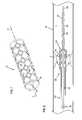
- FIG. 1is a perspective view of a stent according to the present invention
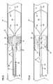
- FIG. 2is a side sectional view of a delivery system according to present invention shown in a body lumen;
- FIG. 3is the view of FIG. 2 with a distal balloon shown in an inflated state
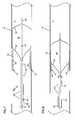
- FIG. 4is the view of FIG. 3 following ejection of a drug-laden hydrogel into the body lumen and surrounding the occlusion;
- FIG. 5is the view of FIG. 4 showing partial expansion of the stent within the body lumen
- FIG. 6is the view of FIG. 5 showing complete expansion of the stent within the body lumen and showing removal of excess amounts of hydrogel from the body lumen;
- FIG. 7is the view of FIG. 6 following completion of removal of the excess amounts of hydrogel and showing initiation of a compression of the stent and remaining hydrogel by the distal balloon;
- FIG. 8is the view of FIG. 7 showing partial compression of the stent and hydrogel by the balloon;
- FIG. 9is the view of FIG. 8 showing complete expansion of the stent and compression of the hydrogel by the distal balloon;
- FIG. 10is the view of FIG. 9 showing the balloon and in deflated state with the delivery system less the stent in process of removal from the body lumen.
- a stent 10is schematically shown in FIG. 1 .
- the stent 10is a reticulated tube having a plurality of struts 12 , which operate as cell-defining portions to define a plurality of open cells 14 extending through an outer cylindrical wall of the stent 10 .
- the struts 12have an inner surface 16 opposing a longitudinal stent axis X-X.
- An outer surface of the cell-defining portionsis provided with a surface depression 18 in the form of a groove.
- the grooveis concave in shape and extends along the outer surface of the cell-defining portions.
- each of the struts 12in cross-section, presents a concave groove on an outer surface of the strut 12 .
- the grooveis disposed such that when the stent is urged against the wall W of a body lumen L, the groove becomes an enclosed chamber captured between the struts 12 and the wall W of the body lumen L as will be more described.
- the depressions 18cover or coincide with at least 10% of a total outer surface area of the struts. In another embodiment, the depressions 18 coincide with at least 25% or at least 50% of the total area defined by the outer surfaces of the struts 12 . As best shown in FIG. 2, inner surfaces 19 of the struts are preferably rounded so as to have a convex curvature.
- the stent 10is shown in an enlarged or expanded diameter.
- the material of the stent 10defines the plurality of cells 14 .
- the cells 14are bounded areas which are open (i.e., extend through the wall thickness of the stent 10 ).
- the stentmay be formed through any suitable means including laser or chemical milling. In such processes, a hollow cylindrical tube is milled to remove material and form the open cells 14 .
- the width and thickness of the stent 10is sized for a particular application.
- the stent 10may be sized such that is enlarged diameter is only slightly greater than the internal diameter of the artery.
- the stentmay have an expanded diameter of about 5.5 mm and a reduced diameter of about 2 mm such that the stent may be placed on a catheter and advanced through the arterial system to a deployment site as is conventional.
- the stent 10 as shown in FIG. 1is for illustration purposes only. There are numerous geometries and shapes of stents and cell-defining portions of stents in the prior art which can be applicable to the present invention.
- the stentmay be lined with an inner or outer sleeve such as polyester fabric or EPTFE for tissue ingrowth.
- the stentmay be coated with radiopaque coatings such as platinum, gold, tungsten, or tantalum.
- the stentmay be formed of any one of a wide variety of previously known materials including, without limitation, stainless steel, nitinol, MP35N, tantalum, platinum, gold, Elgiloy and Phynox.
- the stent 10is shown as a self-expanding stent preferably formed of nitinol.
- the stent 10may be a non-self-expanding stent of the construction requiring the application of force (such as inflation of a balloon) to expand the stent to the expanded diameter as is known in the prior art.
- FIG. 2shows a delivery system 20 according to the present invention in position within a body lumen L defined by a wall W.
- the wall Wmay be an artery such as a coronary artery.
- an obstruction O(such as arterial plaque or thrombus) is located within the lumen L and at least partially occluding the lumen L.
- the delivery system 20includes a distal balloon 22 which may be carried on the distal tip of a catheter or, as shown, on the distal tip of a guide wire 24 where the guide wire contains a hollow lumen 26 and with an opening 28 in communication with the balloon 22 . Accordingly, fluid may be selectively admitted under pressure through the lumen 26 and through the opening 28 to cause inflation of the balloon 22 .
- the balloon 22is shown in a deflated state for unobstructed advancement through the lumen L.
- a catheter 30is positioned coaxially surrounding the guide wire 24 and terminating on a proximal side of the balloon 22 .
- the outer cylindrical wall of the catheter 30is provided with a plurality of openings 32 in communication with an inner hollow lumen 34 of the catheter 30 such that material may be ejected from the lumen 34 and through the openings 32 as will be described.
- the stent 10is positioned surrounding the distal end of the catheter 30 with the stent 10 in a reduced diameter or compressed state.
- An outer sheath 40surrounds the catheter 30 and the stent 10 .
- the sheath 40is provided with a plurality of openings 42 positioned opposing the stent 10 .
- the stent 10is a self-expanding stent. When the sheath 40 is retracted proximally, the sheath 40 exposes the stent 10 which may now expand under its bias to an expanded diameter.
- the delivery system 20 as describedis advanced to the position shown in FIG. 2 with the balloon 22 in a deflated state and position distally to the obstruction O.
- the stent 10is positioned within the obstruction O.
- the stent 10has an axial length greater than an axial length of the obstruction O.
- the balloon 22is inflated as illustrated in FIG. 3 .
- the balloon 22is urged against the wall W of the vessel.
- the balloon 22is shown with a proximal end 23 having a sloped shape at an angle of approximately 45 degrees to the guide wire 24 such that the end 23 is generally conical in shape.
- a proximal balloon(not shown) could be inflated on a proximal side of the stent 10 to isolate the obstruction O between two balloons.
- An additional lumen(not shown) could be formed within the guide wire 24 or in an additional catheter to permit blood flow to flow from a proximal side of the second balloon (not shown) to the distal side of the balloon 22 thereby maintaining blood flow distal to balloon 22 .
- a hydrogel 50is ejected through the lumen 34 and through the openings 32 , 42 to set up surrounding the obstruction O as illustrated in FIG. 4 .
- the hydrogel 50is preferably drug-laden with a therapeutic amount of a drug to prevent restonosis or otherwise provide desired therapy to the artery wall W.
- drugs carried within the hydrogel 50may include heparin, heparin fragments, angiotensin converting enzyme inhibitors, angiopeptin, cyclosporin and antibiotics such as rapamycin.
- Other suitable drugsare disclosed in U.S. Pat. No. 6,273,913, which is hereby incorporated by reference in its entirety.
- the hydrogel 50completely surrounds the occlusion O.
- the sheath 40is retracted proximally such that the stent 10 may begin to expand as illustrated in FIG. 5 .
- opposing surfaces of the wall W and the concave cell-defining surfaces 18define a chamber captured between the stent 10 and the wall W.
- a portion of the drug-laden hydrogel 50is captured within the chamber and abutting the wall W.
- the balloon 22 and remaining portions of the delivery system 20are retracted as illustrated in FIGS. 7-9 with the balloon 22 urging further expansion of the stent 10 and urging the hydrogel 50 to be compressed within the interstitial spaces of the stent 10 .
- the balloon 22maybe deflated as illustrated in FIG. 10 such that the remaining elements of the delivery system (i.e., the complete delivery system 20 less the stent 10 ) can be proximally withdrawn through the vessel lumen L.
- the stent 10being positioned urging the obstruction O against the wall W of the vessel and maintaining the wall W of the vessel in an expanded and open state.
- a portion of the drug-laden hydrogel 50is captured within the chamber defined between the concave surfaces 18 of the stent 10 and the wall W of the vessel. Therefore, the drug may be eluded through the hydrogel 50 over time to provide a therapeutic effect to the wall W of the vessel.
- a portion of the hydrogel 50may reside within the interstitial spaces or open cells between opposing cell-defining struts 12 to provide additional therapeutic effect.
Landscapes
- Health & Medical Sciences (AREA)
- Engineering & Computer Science (AREA)
- Biomedical Technology (AREA)
- Cardiology (AREA)
- Oral & Maxillofacial Surgery (AREA)
- Transplantation (AREA)
- Heart & Thoracic Surgery (AREA)
- Vascular Medicine (AREA)
- Life Sciences & Earth Sciences (AREA)
- Animal Behavior & Ethology (AREA)
- General Health & Medical Sciences (AREA)
- Public Health (AREA)
- Veterinary Medicine (AREA)
- Physics & Mathematics (AREA)
- Optics & Photonics (AREA)
- Materials For Medical Uses (AREA)
Abstract
Description
Claims (8)
Priority Applications (1)
| Application Number | Priority Date | Filing Date | Title |
|---|---|---|---|
| US10/269,878US6699275B1 (en) | 2002-10-11 | 2002-10-11 | Stent and delivery system |
Applications Claiming Priority (1)
| Application Number | Priority Date | Filing Date | Title |
|---|---|---|---|
| US10/269,878US6699275B1 (en) | 2002-10-11 | 2002-10-11 | Stent and delivery system |
Publications (1)
| Publication Number | Publication Date |
|---|---|
| US6699275B1true US6699275B1 (en) | 2004-03-02 |
Family
ID=31715406
Family Applications (1)
| Application Number | Title | Priority Date | Filing Date |
|---|---|---|---|
| US10/269,878Expired - Fee RelatedUS6699275B1 (en) | 2002-10-11 | 2002-10-11 | Stent and delivery system |
Country Status (1)
| Country | Link |
|---|---|
| US (1) | US6699275B1 (en) |
Cited By (22)
| Publication number | Priority date | Publication date | Assignee | Title |
|---|---|---|---|---|
| US20040158308A1 (en)* | 2002-12-24 | 2004-08-12 | Novostent Corporation | Delivery catheter for ribbon-type prosthesis and methods of use |
| US20050119721A1 (en)* | 2002-12-31 | 2005-06-02 | Dmitry Rabkin | Stent delivery system |
| US20050183259A1 (en)* | 2004-02-23 | 2005-08-25 | Tracee Eidenschink | Apparatus and method for crimping a stent assembly |
| US20070043381A1 (en)* | 2005-08-19 | 2007-02-22 | Icon Medical Corp. | Medical device deployment instrument |
| US20070225781A1 (en)* | 2006-03-21 | 2007-09-27 | Nidus Medical, Llc | Apparatus and methods for altering temperature in a region within the body |
| US20080077230A1 (en)* | 2006-09-21 | 2008-03-27 | Barry Heaney | Stent with support element |
| US20080140179A1 (en)* | 2006-12-12 | 2008-06-12 | Ladisa John F | Apparatus and method for minimizing flow disturbances in a stented region of a lumen |
| WO2008073496A3 (en)* | 2006-12-12 | 2008-10-09 | John F Ladisa Jr | Apparatus and method for minimizing flow disturbances in a stented region of a lumen |
| US8216295B2 (en) | 2008-07-01 | 2012-07-10 | Endologix, Inc. | Catheter system and methods of using same |
| US8333003B2 (en) | 2008-05-19 | 2012-12-18 | Boston Scientific Scimed, Inc. | Bifurcation stent crimping systems and methods |
| US8731676B2 (en) | 2011-05-19 | 2014-05-20 | Neuros Medical, Inc. | High-frequency electrical nerve block |
| US9295841B2 (en) | 2011-05-19 | 2016-03-29 | Meuros Medical, Inc. | High-frequency electrical nerve block |
| US9549835B2 (en) | 2011-03-01 | 2017-01-24 | Endologix, Inc. | Catheter system and methods of using same |
| WO2018026818A1 (en)* | 2016-08-02 | 2018-02-08 | Boston Scientific Scimed, Inc. | Stent delivery system |
| USD864387S1 (en)* | 2017-05-02 | 2019-10-22 | Affera, Inc. | Catheter tip with openings |
| US10758723B2 (en) | 2011-05-19 | 2020-09-01 | Neuros Medical, Inc. | Nerve cuff electrode for neuromodulation in large human nerve trunks |
| US11116965B2 (en) | 2017-12-13 | 2021-09-14 | Neuros Medical, Inc. | Nerve cuff deployment devices |
| US11129737B2 (en) | 2015-06-30 | 2021-09-28 | Endologix Llc | Locking assembly for coupling guidewire to delivery system |
| US11213682B2 (en) | 2018-04-09 | 2022-01-04 | Neuros Medical, Inc. | Apparatuses and methods for setting an electrical dose |
| US11413458B2 (en) | 2011-05-19 | 2022-08-16 | Neuros Medical, Inc. | Nerve cuff electrode for neuromodulation in large human nerve trunks |
| US11878172B2 (en) | 2020-02-11 | 2024-01-23 | Neuros Medical, Inc. | System and method for quantifying qualitative patient-reported data sets |
| USD1074999S1 (en)* | 2019-12-16 | 2025-05-13 | Affera, Inc. | Catheter tip with electrode panel(s) |
Citations (15)
| Publication number | Priority date | Publication date | Assignee | Title |
|---|---|---|---|---|
| US5449373A (en) | 1994-03-17 | 1995-09-12 | Medinol Ltd. | Articulated stent |
| US5695516A (en) | 1996-02-21 | 1997-12-09 | Iso Stent, Inc. | Longitudinally elongating balloon expandable stent |
| US5855563A (en)* | 1992-11-02 | 1999-01-05 | Localmed, Inc. | Method and apparatus for sequentially performing multiple intraluminal procedures |
| JPH11347131A (en)* | 1998-06-11 | 1999-12-21 | Medikit Kk | Catheter introducer |
| US6071305A (en)* | 1996-11-25 | 2000-06-06 | Alza Corporation | Directional drug delivery stent and method of use |
| US6206915B1 (en) | 1998-09-29 | 2001-03-27 | Medtronic Ave, Inc. | Drug storing and metering stent |
| US6254632B1 (en)* | 2000-09-28 | 2001-07-03 | Advanced Cardiovascular Systems, Inc. | Implantable medical device having protruding surface structures for drug delivery and cover attachment |
| US6253443B1 (en)* | 1997-09-30 | 2001-07-03 | Scimed Life Systems, Inc. | Method of forming a stent |
| US6273913B1 (en) | 1997-04-18 | 2001-08-14 | Cordis Corporation | Modified stent useful for delivery of drugs along stent strut |
| US6287291B1 (en)* | 1999-11-09 | 2001-09-11 | Advanced Cardiovascular Systems, Inc. | Protective sheath for catheters |
| US6312454B1 (en)* | 1996-06-13 | 2001-11-06 | Nitinol Devices & Components | Stent assembly |
| US6558733B1 (en)* | 2000-10-26 | 2003-05-06 | Advanced Cardiovascular Systems, Inc. | Method for etching a micropatterned microdepot prosthesis |
| US6562065B1 (en)* | 1998-03-30 | 2003-05-13 | Conor Medsystems, Inc. | Expandable medical device with beneficial agent delivery mechanism |
| US6569145B1 (en)* | 1999-03-25 | 2003-05-27 | Transvascular, Inc. | Pressure-controlled continuous coronary sinus occlusion device and methods of use |
| US6579305B1 (en)* | 1995-12-07 | 2003-06-17 | Medtronic Ave, Inc. | Method and apparatus for delivery deployment and retrieval of a stent comprising shape-memory material |
- 2002
- 2002-10-11USUS10/269,878patent/US6699275B1/ennot_activeExpired - Fee Related
Patent Citations (15)
| Publication number | Priority date | Publication date | Assignee | Title |
|---|---|---|---|---|
| US5855563A (en)* | 1992-11-02 | 1999-01-05 | Localmed, Inc. | Method and apparatus for sequentially performing multiple intraluminal procedures |
| US5449373A (en) | 1994-03-17 | 1995-09-12 | Medinol Ltd. | Articulated stent |
| US6579305B1 (en)* | 1995-12-07 | 2003-06-17 | Medtronic Ave, Inc. | Method and apparatus for delivery deployment and retrieval of a stent comprising shape-memory material |
| US5695516A (en) | 1996-02-21 | 1997-12-09 | Iso Stent, Inc. | Longitudinally elongating balloon expandable stent |
| US6312454B1 (en)* | 1996-06-13 | 2001-11-06 | Nitinol Devices & Components | Stent assembly |
| US6071305A (en)* | 1996-11-25 | 2000-06-06 | Alza Corporation | Directional drug delivery stent and method of use |
| US6273913B1 (en) | 1997-04-18 | 2001-08-14 | Cordis Corporation | Modified stent useful for delivery of drugs along stent strut |
| US6253443B1 (en)* | 1997-09-30 | 2001-07-03 | Scimed Life Systems, Inc. | Method of forming a stent |
| US6562065B1 (en)* | 1998-03-30 | 2003-05-13 | Conor Medsystems, Inc. | Expandable medical device with beneficial agent delivery mechanism |
| JPH11347131A (en)* | 1998-06-11 | 1999-12-21 | Medikit Kk | Catheter introducer |
| US6206915B1 (en) | 1998-09-29 | 2001-03-27 | Medtronic Ave, Inc. | Drug storing and metering stent |
| US6569145B1 (en)* | 1999-03-25 | 2003-05-27 | Transvascular, Inc. | Pressure-controlled continuous coronary sinus occlusion device and methods of use |
| US6287291B1 (en)* | 1999-11-09 | 2001-09-11 | Advanced Cardiovascular Systems, Inc. | Protective sheath for catheters |
| US6254632B1 (en)* | 2000-09-28 | 2001-07-03 | Advanced Cardiovascular Systems, Inc. | Implantable medical device having protruding surface structures for drug delivery and cover attachment |
| US6558733B1 (en)* | 2000-10-26 | 2003-05-06 | Advanced Cardiovascular Systems, Inc. | Method for etching a micropatterned microdepot prosthesis |
Cited By (39)
| Publication number | Priority date | Publication date | Assignee | Title |
|---|---|---|---|---|
| US7666216B2 (en)* | 2002-12-24 | 2010-02-23 | Novostent Corporation | Delivery catheter for ribbon-type prosthesis and methods of use |
| US20040158308A1 (en)* | 2002-12-24 | 2004-08-12 | Novostent Corporation | Delivery catheter for ribbon-type prosthesis and methods of use |
| US20050119721A1 (en)* | 2002-12-31 | 2005-06-02 | Dmitry Rabkin | Stent delivery system |
| US7074236B2 (en)* | 2002-12-31 | 2006-07-11 | Intek Technology L.L.C. | Stent delivery system |
| US20050183259A1 (en)* | 2004-02-23 | 2005-08-25 | Tracee Eidenschink | Apparatus and method for crimping a stent assembly |
| US7225518B2 (en) | 2004-02-23 | 2007-06-05 | Boston Scientific Scimed, Inc. | Apparatus for crimping a stent assembly |
| US20070043381A1 (en)* | 2005-08-19 | 2007-02-22 | Icon Medical Corp. | Medical device deployment instrument |
| US20070225781A1 (en)* | 2006-03-21 | 2007-09-27 | Nidus Medical, Llc | Apparatus and methods for altering temperature in a region within the body |
| US20080077230A1 (en)* | 2006-09-21 | 2008-03-27 | Barry Heaney | Stent with support element |
| US7875069B2 (en)* | 2006-09-21 | 2011-01-25 | Boston Scientific Scimed, Inc. | Stent with support element |
| US20080140179A1 (en)* | 2006-12-12 | 2008-06-12 | Ladisa John F | Apparatus and method for minimizing flow disturbances in a stented region of a lumen |
| WO2008073496A3 (en)* | 2006-12-12 | 2008-10-09 | John F Ladisa Jr | Apparatus and method for minimizing flow disturbances in a stented region of a lumen |
| US8333003B2 (en) | 2008-05-19 | 2012-12-18 | Boston Scientific Scimed, Inc. | Bifurcation stent crimping systems and methods |
| US8216295B2 (en) | 2008-07-01 | 2012-07-10 | Endologix, Inc. | Catheter system and methods of using same |
| US10512758B2 (en) | 2008-07-01 | 2019-12-24 | Endologix, Inc. | Catheter system and methods of using same |
| US9700701B2 (en) | 2008-07-01 | 2017-07-11 | Endologix, Inc. | Catheter system and methods of using same |
| US9687374B2 (en) | 2011-03-01 | 2017-06-27 | Endologix, Inc. | Catheter system and methods of using same |
| US9549835B2 (en) | 2011-03-01 | 2017-01-24 | Endologix, Inc. | Catheter system and methods of using same |
| US12239558B2 (en) | 2011-03-01 | 2025-03-04 | Endologix Llc | Catheter system and methods of using same |
| US10660775B2 (en) | 2011-03-01 | 2020-05-26 | Endologix, Inc. | Catheter system and methods of using same |
| US8731676B2 (en) | 2011-05-19 | 2014-05-20 | Neuros Medical, Inc. | High-frequency electrical nerve block |
| US12011597B2 (en) | 2011-05-19 | 2024-06-18 | Neuros Medical, Inc. | Nerve cuff electrode for neuromodulation in large human nerve trunks |
| US8983612B2 (en) | 2011-05-19 | 2015-03-17 | Neuros Medical, Inc. | High-frequency electrical nerve block |
| US10758723B2 (en) | 2011-05-19 | 2020-09-01 | Neuros Medical, Inc. | Nerve cuff electrode for neuromodulation in large human nerve trunks |
| US9295841B2 (en) | 2011-05-19 | 2016-03-29 | Meuros Medical, Inc. | High-frequency electrical nerve block |
| US11413458B2 (en) | 2011-05-19 | 2022-08-16 | Neuros Medical, Inc. | Nerve cuff electrode for neuromodulation in large human nerve trunks |
| US11129737B2 (en) | 2015-06-30 | 2021-09-28 | Endologix Llc | Locking assembly for coupling guidewire to delivery system |
| US12186215B2 (en) | 2015-06-30 | 2025-01-07 | Endologix Llc | Locking assembly for coupling guidewire to delivery system |
| JP2019527115A (en)* | 2016-08-02 | 2019-09-26 | ボストン サイエンティフィック サイムド,インコーポレイテッドBoston Scientific Scimed,Inc. | Stent delivery system |
| WO2018026818A1 (en)* | 2016-08-02 | 2018-02-08 | Boston Scientific Scimed, Inc. | Stent delivery system |
| USD864387S1 (en)* | 2017-05-02 | 2019-10-22 | Affera, Inc. | Catheter tip with openings |
| USD963163S1 (en)* | 2017-05-02 | 2022-09-06 | Affera, Inc. | Catheter tip with openings |
| US11752331B2 (en) | 2017-12-13 | 2023-09-12 | Neuros Medical, Inc. | Nerve cuff deployment devices |
| US11116965B2 (en) | 2017-12-13 | 2021-09-14 | Neuros Medical, Inc. | Nerve cuff deployment devices |
| US11730963B2 (en) | 2018-04-09 | 2023-08-22 | Neuros Medical, Inc. | Apparatuses and methods for setting an electrical dose |
| US11213682B2 (en) | 2018-04-09 | 2022-01-04 | Neuros Medical, Inc. | Apparatuses and methods for setting an electrical dose |
| US12201837B2 (en) | 2018-04-09 | 2025-01-21 | Neuros Medical, Inc. | Apparatuses and methods for setting an electrical dose |
| USD1074999S1 (en)* | 2019-12-16 | 2025-05-13 | Affera, Inc. | Catheter tip with electrode panel(s) |
| US11878172B2 (en) | 2020-02-11 | 2024-01-23 | Neuros Medical, Inc. | System and method for quantifying qualitative patient-reported data sets |
Similar Documents
| Publication | Publication Date | Title |
|---|---|---|
| US6699275B1 (en) | Stent and delivery system | |
| US7955371B2 (en) | System and method for stent deployment and infusion of a therapeutic agent into tissue adjacent to the stent ends | |
| EP1158934B1 (en) | Stent with varying strut geometry | |
| EP1534181B1 (en) | Centering catheter | |
| US7806923B2 (en) | Side branch stent having a proximal split ring | |
| JP4344384B2 (en) | Method and system for treating side branch ostium | |
| JP4087112B2 (en) | Stent design for use in peripheral vessels | |
| EP2211788B1 (en) | Stent made of wire having a spiral channel for drug delivery | |
| US20040230176A1 (en) | System for treating a vascular condition that inhibits restenosis at stent ends | |
| US9056157B2 (en) | Hybrid biodegradable/non-biodegradable stent, delivery system and method of treating a vascular condition | |
| JP4394461B2 (en) | Overlapping covered stent | |
| US7029493B2 (en) | Stent with enhanced crossability | |
| US6752825B2 (en) | Nested stent apparatus | |
| US20090093871A1 (en) | Medical Implant With Internal Drug Delivery System | |
| EP1155664A2 (en) | A helical stent having flat ends | |
| US20060190072A1 (en) | Flexible cells for axially interconnecting stent components | |
| US20060173530A1 (en) | Flexible cells for interconnecting stent components | |
| US20050075710A1 (en) | Balloonless direct stenting device | |
| CA2353197A1 (en) | Channeled vascular stent apparatus and method | |
| WO2004105646A2 (en) | Devices and methods for treatment of stenotic regions | |
| JP2014511247A (en) | Low strain high strength stent | |
| US20100241069A1 (en) | Ostial lesion stent delivery system | |
| US20050267562A1 (en) | Stent-reduction sleeve | |
| WO2004021929A1 (en) | Modular stent system and delivery means | |
| EP1827303B1 (en) | Vulnerable plaque stent |
Legal Events
| Date | Code | Title | Description |
|---|---|---|---|
| AS | Assignment | Owner name:ALPHA MEDICAL, INC., MINNESOTA Free format text:ASSIGNMENT OF ASSIGNORS INTEREST;ASSIGNORS:KNUDSON, MARK B.;SOPP, JOHN P.;CONRAD, TIMOTHY R.;REEL/FRAME:013803/0441 Effective date:20030211 | |
| AS | Assignment | Owner name:BETA MEDICAL, INC., MINNESOTA Free format text:MERGER;ASSIGNOR:ALPHA MEDICAL, INC.;REEL/FRAME:014891/0131 Effective date:20031113 Owner name:ENTEROMEDICS, INC., MINNESOTA Free format text:CHANGE OF NAME;ASSIGNOR:BETA MEDICAL, INC.;REEL/FRAME:014890/0767 Effective date:20031114 | |
| CC | Certificate of correction | ||
| FPAY | Fee payment | Year of fee payment:4 | |
| AS | Assignment | Owner name:ENTEROMEDICS, INC., A DELAWARE CORPORATION, MINNES Free format text:MERGER;ASSIGNOR:ENTEROMEDICS INC., A MINNESOTA CORPORATION;REEL/FRAME:021998/0785 Effective date:20040728 | |
| AS | Assignment | Owner name:ENTEROMEDICS INC., A DELAWARE CORPORATION, MINNESO Free format text:CORRECTIVE ASSIGNMENT TO CORRECT THE ASSGINEE NAME PREVIOUSLY RECORDED ON REEL 021998 FRAME 0785;ASSIGNOR:ENTEROMEDICS INC., A MINNESOTA CORPORATION;REEL/FRAME:023230/0299 Effective date:20040728 Owner name:ENTEROMEDICS INC., A DELAWARE CORPORATION, MINNESO Free format text:CORRECTIVE ASSIGNMENT TO CORRECT THE ASSGINEE NAME PREVIOUSLY RECORDED ON REEL 021998 FRAME 0785. ASSIGNOR(S) HEREBY CONFIRMS THE MERGER;ASSIGNOR:ENTEROMEDICS INC., A MINNESOTA CORPORATION;REEL/FRAME:023230/0299 Effective date:20040728 | |
| FPAY | Fee payment | Year of fee payment:8 | |
| REMI | Maintenance fee reminder mailed | ||
| LAPS | Lapse for failure to pay maintenance fees | ||
| STCH | Information on status: patent discontinuation | Free format text:PATENT EXPIRED DUE TO NONPAYMENT OF MAINTENANCE FEES UNDER 37 CFR 1.362 | |
| FP | Lapsed due to failure to pay maintenance fee | Effective date:20160302 | |
| AS | Assignment | Owner name:RESHAPE LIFESCIENCES INC., CALIFORNIA Free format text:CHANGE OF NAME;ASSIGNOR:ENTEROMEDICS INC.;REEL/FRAME:045949/0495 Effective date:20171012 |