US6699245B2 - Anastomosis system and related methods - Google Patents
Anastomosis system and related methodsDownload PDFInfo
- Publication number
- US6699245B2 US6699245B2US10/068,777US6877702AUS6699245B2US 6699245 B2US6699245 B2US 6699245B2US 6877702 AUS6877702 AUS 6877702AUS 6699245 B2US6699245 B2US 6699245B2
- Authority
- US
- United States
- Prior art keywords
- anastomosis
- graft
- tissue
- vessel
- conduit
- Prior art date
- Legal status (The legal status is an assumption and is not a legal conclusion. Google has not performed a legal analysis and makes no representation as to the accuracy of the status listed.)
- Expired - Fee Related
Links
Images


Classifications
- A—HUMAN NECESSITIES
- A61—MEDICAL OR VETERINARY SCIENCE; HYGIENE
- A61B—DIAGNOSIS; SURGERY; IDENTIFICATION
- A61B17/00—Surgical instruments, devices or methods
- A61B17/11—Surgical instruments, devices or methods for performing anastomosis; Buttons for anastomosis
- A—HUMAN NECESSITIES
- A61—MEDICAL OR VETERINARY SCIENCE; HYGIENE
- A61F—FILTERS IMPLANTABLE INTO BLOOD VESSELS; PROSTHESES; DEVICES PROVIDING PATENCY TO, OR PREVENTING COLLAPSING OF, TUBULAR STRUCTURES OF THE BODY, e.g. STENTS; ORTHOPAEDIC, NURSING OR CONTRACEPTIVE DEVICES; FOMENTATION; TREATMENT OR PROTECTION OF EYES OR EARS; BANDAGES, DRESSINGS OR ABSORBENT PADS; FIRST-AID KITS
- A61F2/00—Filters implantable into blood vessels; Prostheses, i.e. artificial substitutes or replacements for parts of the body; Appliances for connecting them with the body; Devices providing patency to, or preventing collapsing of, tubular structures of the body, e.g. stents
- A61F2/02—Prostheses implantable into the body
- A61F2/04—Hollow or tubular parts of organs, e.g. bladders, tracheae, bronchi or bile ducts
- A61F2/06—Blood vessels
- A61F2/064—Blood vessels with special features to facilitate anastomotic coupling
- A—HUMAN NECESSITIES
- A61—MEDICAL OR VETERINARY SCIENCE; HYGIENE
- A61B—DIAGNOSIS; SURGERY; IDENTIFICATION
- A61B17/00—Surgical instruments, devices or methods
- A61B17/32—Surgical cutting instruments
- A61B17/3205—Excision instruments
- A61B17/32053—Punch like cutting instruments, e.g. using a cylindrical or oval knife
- A—HUMAN NECESSITIES
- A61—MEDICAL OR VETERINARY SCIENCE; HYGIENE
- A61B—DIAGNOSIS; SURGERY; IDENTIFICATION
- A61B17/00—Surgical instruments, devices or methods
- A61B17/11—Surgical instruments, devices or methods for performing anastomosis; Buttons for anastomosis
- A61B2017/1135—End-to-side connections, e.g. T- or Y-connections
- A—HUMAN NECESSITIES
- A61—MEDICAL OR VETERINARY SCIENCE; HYGIENE
- A61B—DIAGNOSIS; SURGERY; IDENTIFICATION
- A61B17/00—Surgical instruments, devices or methods
- A61B17/11—Surgical instruments, devices or methods for performing anastomosis; Buttons for anastomosis
- A61B2017/1139—Side-to-side connections, e.g. shunt or X-connections
Definitions
- the present inventionrelates generally to medical devices and methods for welding biological tissue.
- the inventionrelates to performing a vascular anastomosis and, more particularly, to preferred devices and methods for sealingly joining a graft vessel, such as a coronary bypass graft, to the side wall of a target vessel, such as the aorta or a coronary artery, in an anastomosis.
- a graft vesselsuch as a coronary bypass graft
- a target vesselsuch as the aorta or a coronary artery
- CABG surgeryA wide variety of medical procedures involve creating an anastomosis to establish fluid communication between two tubular conduits or organs in a patient.
- Coronary artery bypass graft (CABG) surgeryfor example, often involves creating an anastomosis between blood vessels or between a blood vessel and a vascular graft to create or restore a blood flow path to the heart muscles.
- CABG surgeryis necessary to overcome coronary artery disease, wherein plaque build-up on the inner walls of the coronary arteries causes narrowing or complete closure of these arteries. This results in insufficient blood flow and deprives the heart muscle of oxygen and nutrients, leading to ischemia, possible myocardial infarction, and even death.
- CABG surgerymay be performed via a traditional open-chest procedure or a closed-chest or port-access thoracoscopic procedure.
- CABG surgerymay require the creation of one or more anastomosis depending upon whether a “free graft” or a “pedicle graft” is employed.
- a “free graft”is a length of conduit having open proximal and distal ends.
- a proximal anastomosisis required to connect the proximal end of the graft to a source of blood (e.g. the aorta) and a distal anastomosis is required to connect the distal end of the graft to the target vessel (e.g. a coronary artery).
- Free graftsmay be autologous, such as by harvesting a saphenous vein or other venous or arterial conduit from elsewhere in the body, or an artificial conduit, such as Dacron or Goretex tubing.
- a “pedicle graft”is the result of rerouting a less essential artery, such as the internal mammary artery, from it native location so that it may be connected to the coronary artery downstream of the blockage. The proximal end of the graft vessel remains attached in its native position and only one anastomosis is required to connect the distal end of the graft vessel to the target vessel.
- the anastomosismay be between the end of the graft and an aperture in the side wall of the source or target vessel (a so-called “end-to-side” anastomosis) or the anastomosis may be between an aperture in the side wall of the graft and an aperture in the side wall of the source or target vessel (a so-called “side-to-side” anastomosis).
- Coronary arteriestypically have a diameter in the range of between about 1 to 5 mm, and the graft vessels have a diameter on the order of about 1 to 4 mm for an arterial graft such as a mammary artery, or about 4 to 8 mm for a vein graft such as a saphenous vein.
- the free end of the mammary arteryis everted over one end of the ring as a cuff and fixed with a silk ligature that is tied around the most proximal of the circular grooves in the ring.
- the cuffed internal mammary arteryis inserted into an incision in the target coronary artery.
- the ringis fixed in place and sealingly joined to the target coronary artery by tying one or more sutures circumferentially around the target vessel and into one or more circular grooves in the ring.
- An intimal-to-intimal anastomosisresults and dissection of blood between the coronary artery and the cuffed internal mammary artery is largely prevented.
- U.S. Pat. No. 4,350,160discloses a vascular stapling device for creating an end-to-end anastomosis between the internal mammary artery (IMA) or a vein graft and one of the coronary arteries, primarily the left anterior descending coronary artery (LAD).
- IMAinternal mammary artery
- LADleft anterior descending coronary artery
- this devicecan only perform end-to-end anastomoses such that the coronary artery must first be severed and dissected from the surrounding myocardium and the exposed end everted for attachment.
- This techniqueis limited to cases where the coronary artery is totally occluded and there is no loss of blood flow by completely severing the coronary artery downstream of the blockage to make the anastomosis. Consequently, this device is not applicable where the coronary artery is only partially occluded and is not at all applicable to making the proximal side-to-end anastomosis between a bypass graft and the aorta.
- U.S. Pat. No. 5,234,447discloses a vascular stapling device for end-to-side vascular anastomoses.
- a ring-shaped stapleis provided having legs extending from the proximal and distal ends of the ring for joining two blood vessels together in an end-to-side anastomosis.
- this devicedoes not provide a complete system for quickly and automatically performing an anastomosis. Rather, it involves a great deal of manual manipulation of the staple, using hand operated tools to individually deform the distal lines of the staple after the graft has been attached and before it is inserted into the opening made in the aortic wall.
- Another disadvantage of the device of the '447 patentis that the distal lines of the staple pierce the wall of the graft vessel at the point where it is everted over the staples. Piercing the wall of the graft vessel potentially invites leaking of the anastomosis and may compromise the structural integrity of the graft vessel wall, serving as a locus for a dissection or even a tear which could lead to catastrophic failure. Because the staple legs only apply pressure to the anastomosis at selected points, there is a potential for thrombosis.
- U.S. Pat. No. 4,366,819discloses a vascular anastomotic fitting device for end-to-side vascular anastomoses.
- This deviceis a four-part anastomotic fitting having a tubular member over which the graft vessel is everted, a ring flange which engages the aortic wall from within the aortic lumen, and a fixation ring and a locking ring which engage the exterior of the aortic wall.
- Another similar deviceis described in U.S. Pat. No. 4,368,736.
- This deviceis a tubular fitting with a flanged distal end that fastens to the aortic wall with an attachment ring, and a proximal end with a graft fixation collar for attaching to the graft vessel.
- These deviceshave a number of drawbacks that the present invention seeks to overcome.
- the anastomotic fittings describedexpose the foreign material of the anastomotic device to the blood flow path within the arteries. This is undesirable because foreign materials within the blood flow path can have a tendency to cause hemolysis, platelet deposition and thrombosis.
- Immune responses to foreign materialtend to be stronger when the material is exposed to the bloodstream.
- the anastomotic fitting of the '819 patentalso has the potential drawback that the spikes that hold the graft vessel onto the anastomotic fitting are very close to the blood flow path, potentially causing trauma to the blood vessel that could lead to leaks in the anastomosis or compromise of the mechanical integrity of the vessels. Consequently, it is desirable to provide an anastomosis fitting that is atraumatic to the graft vessel as possible. Any sharp features such as attachment spikes should be placed as far away from the blood flow path and the anastomosis site as possible so that there is no compromise of the anastomosis seal or the structural integrity of the vessels.
- the 3M-Unilink device for end-to-end anastomosis(U.S. Pat. Nos. 4,624,257; 4,917,090; 4,917,091) is designed for use in microsurgery, such as for reattaching vessels severed in accidents.
- This deviceprovides an anastomosis clamp that has two eversion rings which are locked together by a series of impaling spikes on their opposing faces.
- this deviceis awkward for use in end-to-side anastomosis and tends to deform the target vessel; therefore it is not currently used in CABG surgery. Due to the delicate process needed to insert the vessels into the device, it would also be unsuitable for port-access surgery.
- anastomosis devicecapable of performing end-to-side and/or side-to-side anastomosis between blood vessels or other hollow organs and vessels. It is also desirable to provide an anastomosis device which minimizes the amount of foreign materials exposed to the blood flow path within the blood vessels and which avoids leakage problems, and which promotes rapid endothelialization and healing. Further, it would be desirable to provide such a device which could be used in port-access CABG surgery. Whether it is used with open-chest or closed-chest surgical techniques, it is also desirable that the invention provide a complete system for quickly and automatically performing an anastomosis with a minimal amount of manual manipulation.
- the present inventioninvolves an anastomosis system and method suitable, by way of example, for use in establishing fluid communication between a graft conduit and a blood vessel in coronary artery bypass graft (CABG) surgery.
- the anastomosis system of the present inventionestablishes such fluid communication by employing tissue fusion technology to effectively fuses the graft conduit to the blood vessel, thereby eliminating the need for connectors or similar prior art devices that remain implanted following the anastomosis procedure.
- the systemmay be used to create side-to-side and/or end-to-side anastomosis connections. It may also be employed in either open-chest or closed chest procedures.
- FIG. 1is a cross-sectional view illustrating an anastomosis method according to a broad principle of the present invention for creating a side-to-side anastomosis between a graft conduit and a blood vessel;
- FIG. 2is a cross-sectional view illustrating an anastomosis method according to a broad principle of the present invention for creating an end-to-side anastomosis between a graft conduit and a blood vessel;
- FIG. 3is a side view illustrating an anastomosis system according to one exemplary embodiment of the present invention particularly suited for creating a side-to-side anastomosis;
- FIG. 4is a partial-sectional view illustrating the anastomosis system as taken along lines 4 — 4 of FIG. 3;
- FIG. 5is an enlarged cross-sectional view illustrating the portion of the anastomosis system within detail 5 of FIG. 4;
- FIGS. 6-11are side views illustrating the method steps in creating a side-to-side anastomosis according to one embodiment of the present invention, using the anastomosis system shown in FIGS. 3-5;
- FIG. 12is a side view illustrating an anastomosis system according to another exemplary embodiment of the present invention.
- FIG. 13is a partial-sectional view illustrating the anastomosis system as taken along lines 13 — 13 of FIG. 12;
- FIG. 14is an enlarged cross-sectional view illustrating the portion of the anastomosis system within detail 14 of FIG. 13;
- FIG. 15is a side view illustrating an anastomosis system according to still further exemplary embodiment of the present invention.
- FIG. 16is a partial-sectional view illustrating the anastomosis system as taken along lines 16 — 16 of FIG. 15;
- FIG. 17is an enlarged cross-sectional view illustrating the portion of the anastomosis system within detail 17 of FIG. 16;
- FIG. 18is a side view illustrating an anastomosis system according to still further exemplary embodiment of the present invention.
- FIG. 19is a partial-sectional view illustrating the anastomosis system as taken along lines 19 — 19 of FIG. 18;
- FIG. 20is an enlarged cross-sectional view illustrating the portion of the anastomosis system within detail 20 of FIG. 19;
- FIGS. 21-23are side views illustrating the method steps in creating and end-to-side anastomosis according to one embodiment of the present invention.
- FIG. 24is a side view illustrating an anastomosis system according to still further exemplary embodiment of the present invention.
- FIG. 25is a partial-sectional view illustrating the anastomosis system as taken along lines 25 — 25 of FIG. 24;
- FIG. 26is an enlarged cross-sectional view illustrating the portion of the anastomosis system within detail 26 of FIG. 25 .
- CABGcoronary artery bypass graft surgery
- the anastomosis system of the present inventionmay be employed in any number of applications and/or procedures wherein it is desired to establish fluid communication between two conduits.
- the anastomosis system and method disclosed hereinboasts a variety of inventive features and attributes that warrant patent protection, both individually and in combination.
- a broad aspect of the anastomosis system and method of the present inventioninvolves fusing a graft conduit to a blood vessel.
- the present inventionadvantageously provides the ability to create either a “side-to-side” anastomosis (FIG. 1) or an “end-to-side” anastomosis (FIG. 2 ).
- the anastomosisis created according to the present invention by: (a) positioning a length of graft conduit 10 in generally mating relationship with a length of blood vessel 12 to establish a graft mating region 14 ; (b) disposing first and second generally ring-shaped tissue fusion element 16 , 18 on either side of the graft mating region 14 ; and (c) activating at least one of the tissue fusion element 16 , 18 to fuse the graft conduit 10 to the blood vessel 12 .
- the graft conduit 10may be a “free graft” or a “pedicle graft.”
- a “free graft”will require a proximal anastomosis to connect the proximal end of the graft to a source of blood (e.g. the aorta) and a distal anastomosis to connect the distal end of the graft to the target vessel (e.g. a coronary artery).
- Free graftsmay be autologous, such as by harvesting a saphenous vein or other venous or arterial conduit from elsewhere in the body, or an artificial conduit, such as Dacron or Goretex tubing.
- a “pedicle graft”will require only one anastomosis to connect the distal end of the graft vessel (e.g. internal mammary artery) to the target vessel.
- the first and second tissue fusion elements 16 , 18may comprise any number of electrodes, devices, or components capable of establishing a suitable union between the graft conduit 10 and the blood vessel 12 .
- tissue fusion or tissue welding technologiesmay include, but are not necessarily limited to, so-called “wet electrode” technology; radio-frequency (RF) technology; ultrasonic technology; bi-polar technology, mono-polar technology, a-polar technology, laser technology, or any other technology (including but not limited to pressure and/or heat) capable of welding or fusing the graft conduit 10 to the blood vessel 12 .
- RFradio-frequency
- ultrasonic technologyultrasonic technology
- bi-polar technologymono-polar technology
- a-polar technologylaser technology
- any other technologyincluding but not limited to pressure and/or heat
- tissue fusion or tissue welding technologiesmay be disclosed in one or more of U.S. Pat. Nos.
- the first and second tissue fusion elements 16 , 18are each dimensioned to encompass a generally circular area on the graft conduit 10 and blood vessel 12 . That is, the first and second tissue fusion elements 16 , 18 are generally ring-shaped such that, when disposed on opposed sides of the graft mating region 14 , a generally circular region is defined within the mating region 14 . Upon activation for an effective period, the first and second tissue fusion elements 16 , 18 weld or fuse the graft conduit 10 and the blood vessel 12 about the periphery of the generally circular region with the mating region 14 .
- first and second tissue fusion elements 16 , 18are designed to cut or sever through the tissue at the same general time the fusion or welding is taking place. In this fashion, a generally circular union is formed in the approximate area of the ring-shaped first and second tissue fusion elements 16 , 18 and the generally circular region within the graft mating region 14 is free from subsequent removal. Fluid communication is thus established between the inner lumen of the graft conduit 10 and the blood vessel 12 . In an alternate embodiment, fluid communication may be established by manually cutting an aperture within the generally circular union between the graft conduit 10 and the blood vessel 12 .
- the first and second tissue fusion elements 16 , 18are shown by way of example only, disposed within structural elements 20 , 22 .
- Structural elements 20 , 22are meant to generally denote a vehicle for disposing the tissue fusion elements 16 , 18 in position on either side of the graft mating region 14 .
- a variety of other such vehiclesmay be employed to serve this purpose without departing from the scope of the present invention.
- the process of creating an end-to-side anastomosismay be facilitated by optionally employing a mechanism for retaining or biasing the distal end of the graft conduit 10 inwardly about the end of the structural element 20 .
- such a retaining or biasing mechanismmay comprise a mesh section 24 disposed along the distal surface of the structural element 20 .
- the mesh section 24serves this retaining or biasing function by providing a surface through which a physician may secure one or more sutures 26 that extend through the distal end of the graft conduit 10 .
- establishment of the graft mating region 14is ensured such that, when activated, the first and second tissue fusion elements 16 , 18 fuse and thus form a secure end-to-side anastomosis.
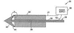
- FIGS. 3-5illustrate an anastomosis system 30 according to one embodiment of the present invention.
- the anastomosis system 30comprises a generally cylindrical base member 32 which houses the generally ring-shaped tissue fusion element 16 , a penetrating member 34 which houses the generally ring-shaped tissue fusion element 18 , and a power supply 36 for activating the first and second tissue fusion elements 16 , 18 .
- the base member 32 and the penetrating member 34provide a mechanism for disposing the first and second tissue fusion elements 16 , 18 on either side of a graft mating region 14 as shown in FIGS. 1-2.
- the penetrating member 34includes an elongated section 38 slideably disposed within a lumen 39 formed in the base member 32 and a tissue-piercing section 40 having the tissue fusion element 18 disposed near its proximal end.
- the tissue-piercing section 38may be selectively advanced through the graft conduit and blood vessel (in a side-to-side anastomosis) and then retracted to position the second tissue fusion element 18 against the inside of the blood vessel.
- the power supply 36may be coupled to the first and second tissue fusion elements 16 , 18 through the use of electrical wire 41 , 42 .
- FIGS. 6-11illustrate a method of creating a side-to-side anastomosis according to a broad aspect of the present invention, employing (by way of example) the anastomosis system 30 shown in FIGS. 3-5.
- the first stepinvolves positioning the graft conduit 10 in a mating relationship with a portion of the blood vessel 12 . Doing so creates the graft mating region shown generally at 14 .
- the second step(FIG.
- the next stepinvolves withdrawing the penetrating member 34 such that the first and second tissue fusion elements 16 , 18 are disposed on either side of the graft mating region 14 .
- the power supplymay then be activated such that the first and second tissue fusion elements 16 , 18 effectively fuse or weld the graft conduit 10 to the blood vessel 12 .
- the tissue fusion elements 16 , 18simultaneously sever or cut out a region disposed within the fused or welded region.
- the severed regionmay be easily removed from the anastomosis site within a concavity 44 formed within the tissue-piercing section 40 . That is, the base member 32 and penetrating member 34 may be removed immediately following fusion (without being slideably separated) while retaining the severed section within the concavity 40 .
- the result of such fusion and removalis a flow port (shown generally at 46 in FIGS.
- the last stepinvolves sealing the open distal end of the graft conduit 10 , such as through the use of a tissue-welding or tissue-fusing forceps 48 of a type well known in the art.
- the end resultis a side-to-side anastomosis between the graft conduit 10 and the blood vessel 12 which does not leave any foreign articles (such as staples) exposed to blood flow, and which is easy and takes very little time to perform.
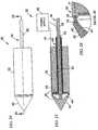
- FIGS. 12-14illustrate an anastomosis system 30 according to another embodiment of the present invention.
- the anastomosis system 30is generally similar to the embodiment shown in FIGS. 3-5 with the exception of the penetrating member 34 .
- the tissue-piercing section 40 of the penetrating member 34has a surface of varying pitch between a tip 50 and the remainder of the tissue-piercing section 40 .
- the embodiment of FIGS. 12-14is identical in design and operation to that previously described with reference to FIGS. 3-5 such that a repeat discussion is not necessary.
- FIGS. 15-17Another system for creating a side-to-side anastomosis according to the present invention is shown in FIGS. 15-17.
- An anastomosis system 30is shown according to another embodiment of the present invention.
- the anastomosis system 30is generally similar to the embodiment shown above with the exception of the penetrating member 34 .
- the penetrating member 34has an inner lumen 53 for slideably receiving an elongated stylet 52 having a tip 51 which, in use, provides a surface of varying pitch between the tip 50 and the remainder of the tissue-piercing section 40 .
- the sharp tip 51 of the sytlet 52facilitates piercing through the graft mating region 14 and may be withdrawn (partially or fully) before, during, or after fusion.
- the embodiment of FIGS. 12-14is identical in design and operation to that previously described above such that a repeat discussion is not necessary.
- FIGS. 3-5 and 12 - 17has been described in terms of forming side-to-side anastomosis according to the present invention, it is to be readily appreciated that these embodiments can be used to perform end-to-side anastomosis as well.
- the distal end of the graft conduit 10may be maintained in position over the first tissue fusion element 16 (as shown in FIG. 2) without the use of the mesh section 24 .
- the penetrating member 34may be advance completely through the blood vessel 12 while maintaining the base member 32 in position with the distal end of the graft conduit 10 sandwiched against the exterior of the blood vessel 12 .
- the first and second tissue fusion elements 16 , 18are then in position such that they may be activated via the power supply 36 to fuse the end of the graft conduit 10 to the side of the blood vessel 12 .
- this fusion processwill also cut or sever the region disposed within the ring-shaped first and second tissue fusion elements 16 , 18 . Due to the concavity 44 , the cut or severed material may be easily removed by simply maintaining the tissue-piercing section 40 in close proximity to the base member 32 during removal. This process is represented generally in FIGS. 21-23.
- a mechanism or devicemay be provided to aid in maintaining the distal end of the graft conduit 10 in proper position for an end-to-side anastomosis.
- the anastomosis system 30may be equipped with a mesh section 24 along the distal end of the base member 32 .
- the mesh section 24may allow a surgeon to suture the end of the graft conduit 10 to the end of the base member 32 to maintain it in that position during introduction into the anastomosis site.
- tissue-piercing section 40may be advanced in the manner described above to the position the first and second tissue fusion elements 16 , 18 on either side of the graft mating region 14 (FIGS. 21 - 22 ), after which point the fusion process may be undertaken to fuse the graft conduit 10 to the blood vessel 12 , leaving a flow port 46 therebetween (FIG. 23 ).
- FIGS. 24-26illustrate an anastomosis system 30 according to another embodiment of the present invention.
- the anastomosis system 30is generally similar to the embodiment shown in FIGS. 18-20 with the exception of the manner of retaining the distal end of the graft conduit 10 during introduction. More specifically, a slideable retaining member 60 is provided within the lumen 39 within the base member 32 .
- the retaining member 60includes a flange 62 which, due to the slideable relation of the retaining member 60 , may be selectively advanced to receive the distal end of the graft conduit 10 therein and then withdrawn to sandwich the distal end of the graft conduit 10 therein until after the fusion process.
- this embodimentis identical in design and operation to that previously described with reference to FIGS. 1 and 18 - 20 such that a repeat discussion is not necessary.
Landscapes
- Health & Medical Sciences (AREA)
- Life Sciences & Earth Sciences (AREA)
- General Health & Medical Sciences (AREA)
- Public Health (AREA)
- Engineering & Computer Science (AREA)
- Biomedical Technology (AREA)
- Heart & Thoracic Surgery (AREA)
- Surgery (AREA)
- Veterinary Medicine (AREA)
- Animal Behavior & Ethology (AREA)
- Medical Informatics (AREA)
- Nuclear Medicine, Radiotherapy & Molecular Imaging (AREA)
- Molecular Biology (AREA)
- Gastroenterology & Hepatology (AREA)
- Pulmonology (AREA)
- Cardiology (AREA)
- Oral & Maxillofacial Surgery (AREA)
- Transplantation (AREA)
- Vascular Medicine (AREA)
- Prostheses (AREA)
- Surgical Instruments (AREA)
Abstract
Description
Claims (2)
Priority Applications (1)
| Application Number | Priority Date | Filing Date | Title |
|---|---|---|---|
| US10/068,777US6699245B2 (en) | 2001-02-05 | 2002-02-05 | Anastomosis system and related methods |
Applications Claiming Priority (2)
| Application Number | Priority Date | Filing Date | Title |
|---|---|---|---|
| US26669401P | 2001-02-05 | 2001-02-05 | |
| US10/068,777US6699245B2 (en) | 2001-02-05 | 2002-02-05 | Anastomosis system and related methods |
Publications (2)
| Publication Number | Publication Date |
|---|---|
| US20020128672A1 US20020128672A1 (en) | 2002-09-12 |
| US6699245B2true US6699245B2 (en) | 2004-03-02 |
Family
ID=23015620
Family Applications (1)
| Application Number | Title | Priority Date | Filing Date |
|---|---|---|---|
| US10/068,777Expired - Fee RelatedUS6699245B2 (en) | 2001-02-05 | 2002-02-05 | Anastomosis system and related methods |
Country Status (2)
| Country | Link |
|---|---|
| US (1) | US6699245B2 (en) |
| WO (1) | WO2002069813A2 (en) |
Cited By (42)
| Publication number | Priority date | Publication date | Assignee | Title |
|---|---|---|---|---|
| US20040082850A1 (en)* | 2002-10-23 | 2004-04-29 | Medtonic, Inc. | Methods and apparatus for locating body vessels and occlusions in body vessels |
| US20040167515A1 (en)* | 2003-02-24 | 2004-08-26 | Intuitive Surgical, Inc., A Delaware Corporation | Surgical tool having electrocautery energy supply conductor with inhibited current leakage |
| US20050228212A1 (en)* | 1998-05-15 | 2005-10-13 | A-Med Systems, Inc. | Pulmonary and circulatory blood flow support devices and methods for heart surgery procedures |
| US20060025811A1 (en)* | 2004-07-28 | 2006-02-02 | Ethicon Endo-Surgery, Inc. | Surgical instrument incorporating an electrically actuated articulation mechanism |
| US20060025813A1 (en)* | 2004-07-28 | 2006-02-02 | Ethicon Endo-Surgery, Inc. | Surgical stapling instrument having an electroactive polymer actuated medical substance dispenser |
| US20060025810A1 (en)* | 2004-07-28 | 2006-02-02 | Ethicon Endo-Surgery, Inc. | Surgical instrument incorporating an electrically actuated articulation locking mechanism |
| US20060111698A1 (en)* | 2004-11-22 | 2006-05-25 | Kihong Kwon | Apparatus and method for performing laser-assisted vascular anastomoses |
| US20060142788A1 (en)* | 2004-12-23 | 2006-06-29 | C. R. Bard, Inc. | Blood vessel transecting and anastomosis |
| US20060212069A1 (en)* | 2005-03-17 | 2006-09-21 | Ethicon Endo-Surgery, Inc. | Surgical stapling instrument having load sensing control circuitry |
| US20070129726A1 (en)* | 2005-05-12 | 2007-06-07 | Eder Joseph C | Electrocautery method and apparatus |
| US20070203479A1 (en)* | 2003-02-13 | 2007-08-30 | Coaptus Medical Corporation | Transseptal closure of a patent foramen ovale and other cardiac defects |
| US20080172052A1 (en)* | 2006-05-02 | 2008-07-17 | Joseph Eder | Surgical Tool |
| US20080221565A1 (en)* | 2005-05-12 | 2008-09-11 | Joseph Charles Eder | Electrocautery method and apparatus |
| US20090198272A1 (en)* | 2008-02-06 | 2009-08-06 | Lawrence Kerver | Method and apparatus for articulating the wrist of a laparoscopic grasping instrument |
| WO2010127362A1 (en)* | 2009-05-01 | 2010-11-04 | Aragon Surgical, Inc. | Method and apparatus for rf anastomosis |
| US7862579B2 (en) | 2004-07-28 | 2011-01-04 | Ethicon Endo-Surgery, Inc. | Electroactive polymer-based articulation mechanism for grasper |
| US7914551B2 (en) | 2004-07-28 | 2011-03-29 | Ethicon Endo-Surgery, Inc. | Electroactive polymer-based articulation mechanism for multi-fire surgical fastening instrument |
| US20110087211A1 (en)* | 2009-10-09 | 2011-04-14 | Coaptus Medical Corporation | Tissue-penetrating guidewires with shaped tips, and associated systems and methods |
| US20110152861A1 (en)* | 2009-12-17 | 2011-06-23 | Aesculap Ag | Surgical System For Connecting Body Tissue |
| US20110202058A1 (en)* | 2005-05-12 | 2011-08-18 | Joseph Eder | Apparatus for Tissue Cauterization |
| US20110230875A1 (en)* | 2008-02-06 | 2011-09-22 | Erik Walberg | Articulable electrosurgical instrument with a stabilizable articulation actuator |
| US20110238062A1 (en)* | 2010-03-26 | 2011-09-29 | Tim Koss | Impedance Mediated Power Delivery for Electrosurgery |
| US20110238056A1 (en)* | 2010-03-26 | 2011-09-29 | Tim Koss | Impedance mediated control of power delivery for electrosurgery |
| US8317074B2 (en) | 2004-07-28 | 2012-11-27 | Ethicon Endo-Surgery, Inc. | Electroactive polymer-based articulation mechanism for circular stapler |
| US20140012248A1 (en)* | 2010-02-12 | 2014-01-09 | Stefan Josef Matthias Kraemer | Apparatus and method for gastric bypass surgery |
| US8728072B2 (en) | 2005-05-12 | 2014-05-20 | Aesculap Ag | Electrocautery method and apparatus |
| US20140309634A1 (en)* | 2011-11-10 | 2014-10-16 | Aesculap Ag | Anastomosis device with collapsible distal head element |
| US8951276B2 (en) | 2011-11-04 | 2015-02-10 | Avenu Medical, Inc. | Systems and methods for percutaneous intravascular access and guidewire placement |
| US9138230B1 (en) | 2011-04-29 | 2015-09-22 | Avenu Medical, Inc. | Systems and methods for creating arteriovenous (AV) fistulas |
| US9173698B2 (en) | 2010-09-17 | 2015-11-03 | Aesculap Ag | Electrosurgical tissue sealing augmented with a seal-enhancing composition |
| US9339327B2 (en) | 2011-06-28 | 2016-05-17 | Aesculap Ag | Electrosurgical tissue dissecting device |
| US9439728B2 (en) | 2010-06-15 | 2016-09-13 | Avenu Medical, Inc. | Systems for creating arteriovenous (AV) fistulas |
| US9439710B2 (en) | 2012-11-14 | 2016-09-13 | Avenu Medical, Inc. | Intravascular arterial to venous anastomosis and tissue welding catheter |
| US9452015B2 (en) | 2010-06-15 | 2016-09-27 | Avenu Medical, Inc. | Intravascular arterial to venous anastomosis and tissue welding catheter |
| US9474562B2 (en) | 2012-02-08 | 2016-10-25 | Avenu Medical, Inc. | Intravascular arterial to venous anastomosis and tissue welding catheter |
| US9872724B2 (en) | 2012-09-26 | 2018-01-23 | Aesculap Ag | Apparatus for tissue cutting and sealing |
| US9918778B2 (en) | 2006-05-02 | 2018-03-20 | Aesculap Ag | Laparoscopic radiofrequency surgical device |
| US10070866B1 (en) | 2013-08-01 | 2018-09-11 | Avenu Medical, Inc. | Percutaneous arterial to venous anastomosis clip application catheter system and methods |
| US10499919B2 (en) | 2015-08-21 | 2019-12-10 | Avenu Medical, Inc. | Systems and methods for percutaneous access and formation of arteriovenous fistulas |
| US10772672B2 (en) | 2014-03-06 | 2020-09-15 | Avenu Medical, Inc. | Systems and methods for percutaneous access and formation of arteriovenous fistulas |
| US11207503B2 (en) | 2016-11-11 | 2021-12-28 | Avenu Medical, Inc. | Systems and methods for percutaneous intravascular access and guidewire placement |
| US11751876B2 (en) | 2019-05-07 | 2023-09-12 | Easyflomicro Inc. | Apparatuses for anastomosis of tubular vessels and related methods |
Families Citing this family (18)
| Publication number | Priority date | Publication date | Assignee | Title |
|---|---|---|---|---|
| US7257450B2 (en) | 2003-02-13 | 2007-08-14 | Coaptus Medical Corporation | Systems and methods for securing cardiovascular tissue |
| US8021362B2 (en) | 2003-03-27 | 2011-09-20 | Terumo Kabushiki Kaisha | Methods and apparatus for closing a layered tissue defect |
| US7186251B2 (en) | 2003-03-27 | 2007-03-06 | Cierra, Inc. | Energy based devices and methods for treatment of patent foramen ovale |
| US6939348B2 (en) | 2003-03-27 | 2005-09-06 | Cierra, Inc. | Energy based devices and methods for treatment of patent foramen ovale |
| US7293562B2 (en) | 2003-03-27 | 2007-11-13 | Cierra, Inc. | Energy based devices and methods for treatment of anatomic tissue defects |
| US7165552B2 (en) | 2003-03-27 | 2007-01-23 | Cierra, Inc. | Methods and apparatus for treatment of patent foramen ovale |
| US7972330B2 (en) | 2003-03-27 | 2011-07-05 | Terumo Kabushiki Kaisha | Methods and apparatus for closing a layered tissue defect |
| AU2004226374B2 (en) | 2003-03-27 | 2009-11-12 | Terumo Kabushiki Kaisha | Methods and apparatus for treatment of patent foramen ovale |
| US7311701B2 (en) | 2003-06-10 | 2007-12-25 | Cierra, Inc. | Methods and apparatus for non-invasively treating atrial fibrillation using high intensity focused ultrasound |
| US7367975B2 (en) | 2004-06-21 | 2008-05-06 | Cierra, Inc. | Energy based devices and methods for treatment of anatomic tissue defects |
| US7473252B2 (en) | 2004-10-07 | 2009-01-06 | Coaptus Medical Corporation | Systems and methods for shrinking and/or securing cardiovascular tissue |
| US8109274B2 (en) | 2005-04-11 | 2012-02-07 | Terumo Kabushiki Kaisha | Methods and electrode apparatus to achieve a closure of a layered tissue defect |
| US20070093804A1 (en)* | 2005-10-17 | 2007-04-26 | Coaptus Medical Corporation | Control systems for patient devices, including devices for securing cardiovascular tissue, and associated methods |
| DE102009027813A1 (en) | 2009-07-17 | 2011-01-27 | Celon Ag Medical Instruments | Anastomosis ring and anastomosis ring arrangement |
| DE102010035470B4 (en)* | 2010-08-26 | 2015-08-13 | Fraunhofer-Gesellschaft zur Förderung der angewandten Forschung e.V. | Device for performing a side-to-side anastomosis |
| US9161756B2 (en)* | 2012-03-16 | 2015-10-20 | Covidien Lp | Closure tape dispenser |
| EP4027926B1 (en) | 2019-09-13 | 2025-05-21 | Alleviant Medical, Inc. | Systems for forming an anastomosis |
| EP4322865A4 (en)* | 2021-04-12 | 2025-05-14 | Myka Labs, Inc. | FEEDBACK-CONTROLLED ANASTOMOSIS DEVICES |
Citations (53)
| Publication number | Priority date | Publication date | Assignee | Title |
|---|---|---|---|---|
| US4350160A (en) | 1979-11-14 | 1982-09-21 | Kolesov Evgeny V | Instrument for establishing vascular anastomoses |
| US4366819A (en) | 1980-11-17 | 1983-01-04 | Kaster Robert L | Anastomotic fitting |
| US4368736A (en) | 1980-11-17 | 1983-01-18 | Kaster Robert L | Anastomotic fitting |
| US4624257A (en) | 1982-06-24 | 1986-11-25 | Anders Berggren | Surgical instrument for performing anastomosis |
| US4662068A (en) | 1985-11-14 | 1987-05-05 | Eli Polonsky | Suture fusing and cutting apparatus |
| US4892098A (en) | 1985-06-26 | 1990-01-09 | Sauer Jude S | Tubular tissue welding device without moving parts |
| US4917091A (en) | 1982-06-24 | 1990-04-17 | Unilink Ab | Annular fastening means |
| US4955378A (en) | 1988-05-02 | 1990-09-11 | University Of South Florida | Apparatus and methods for performing electrofusion at specific anatomical sites |
| US5071417A (en) | 1990-06-15 | 1991-12-10 | Rare Earth Medical Lasers, Inc. | Laser fusion of biological materials |
| US5140984A (en) | 1983-10-06 | 1992-08-25 | Proclosure, Inc. | Laser healing method and apparatus |
| US5156613A (en) | 1991-02-13 | 1992-10-20 | Interface Biomedical Laboratories Corp. | Collagen welding rod material for use in tissue welding |
| US5217458A (en)* | 1992-04-09 | 1993-06-08 | Everest Medical Corporation | Bipolar biopsy device utilizing a rotatable, single-hinged moving element |
| US5234447A (en) | 1990-08-28 | 1993-08-10 | Robert L. Kaster | Side-to-end vascular anastomotic staple apparatus |
| US5249192A (en) | 1991-06-27 | 1993-09-28 | Laserscope | Multiple frequency medical laser |
| US5272716A (en) | 1991-10-15 | 1993-12-21 | Mcdonnell Douglas Corporation | Hand held laser apparatus |
| US5290278A (en) | 1992-10-20 | 1994-03-01 | Proclosure Inc. | Method and apparatus for applying thermal energy to luminal tissue |
| US5300065A (en) | 1992-11-06 | 1994-04-05 | Proclosure Inc. | Method and apparatus for simultaneously holding and sealing tissue |
| US5334191A (en) | 1992-05-21 | 1994-08-02 | Dix Phillip Poppas | Laser tissue welding control system |
| US5336221A (en) | 1992-10-14 | 1994-08-09 | Premier Laser Systems, Inc. | Method and apparatus for applying thermal energy to tissue using a clamp |
| US5354323A (en) | 1992-10-20 | 1994-10-11 | Premier Laser Systems, Inc. | Optical heating system |
| US5364389A (en) | 1992-11-25 | 1994-11-15 | Premier Laser Systems, Inc. | Method and apparatus for sealing and/or grasping luminal tissue |
| US5403312A (en) | 1993-07-22 | 1995-04-04 | Ethicon, Inc. | Electrosurgical hemostatic device |
| US5409781A (en) | 1992-06-13 | 1995-04-25 | Asea Brown Boveri Ltd. | High-temperature component, especially a turbine blade, and process for producing this component |
| US5409479A (en) | 1983-10-06 | 1995-04-25 | Premier Laser Systems, Inc. | Method for closing tissue wounds using radiative energy beams |
| US5531744A (en) | 1991-11-01 | 1996-07-02 | Medical Scientific, Inc. | Alternative current pathways for bipolar surgical cutting tool |
| US5540684A (en) | 1994-07-28 | 1996-07-30 | Hassler, Jr.; William L. | Method and apparatus for electrosurgically treating tissue |
| US5571216A (en) | 1994-01-19 | 1996-11-05 | The General Hospital Corporation | Methods and apparatus for joining collagen-containing materials |
| US5612050A (en) | 1993-03-23 | 1997-03-18 | Focal, Inc. | Apparatus and method for local application of polymeric material to tissue |
| US5624452A (en) | 1995-04-07 | 1997-04-29 | Ethicon Endo-Surgery, Inc. | Hemostatic surgical cutting or stapling instrument |
| US5662643A (en) | 1994-09-28 | 1997-09-02 | Abiomed R & D, Inc. | Laser welding system |
| US5665085A (en) | 1991-11-01 | 1997-09-09 | Medical Scientific, Inc. | Electrosurgical cutting tool |
| US5693051A (en) | 1993-07-22 | 1997-12-02 | Ethicon Endo-Surgery, Inc. | Electrosurgical hemostatic device with adaptive electrodes |
| US5709680A (en) | 1993-07-22 | 1998-01-20 | Ethicon Endo-Surgery, Inc. | Electrosurgical hemostatic device |
| US5725522A (en) | 1990-06-15 | 1998-03-10 | Rare Earth Medical, Inc. | Laser suturing of biological materials |
| US5749895A (en)* | 1991-02-13 | 1998-05-12 | Fusion Medical Technologies, Inc. | Method for bonding or fusion of biological tissue and material |
| US5810811A (en) | 1993-07-22 | 1998-09-22 | Ethicon Endo-Surgery, Inc. | Electrosurgical hemostatic device |
| US5824015A (en) | 1991-02-13 | 1998-10-20 | Fusion Medical Technologies, Inc. | Method for welding biological tissue |
| US5827265A (en) | 1996-02-07 | 1998-10-27 | Regents Of The University Of California | Intraluminal tissue welding for anastomosis |
| US5846241A (en)* | 1995-12-19 | 1998-12-08 | Johns Hopkins University | Bipolar electrocautery valvulotome |
| US5865830A (en) | 1989-06-07 | 1999-02-02 | Parel; Jean-Marie | Noncontact laser microsurgical apparatus |
| US5871524A (en) | 1995-05-05 | 1999-02-16 | Thermage, Inc. | Apparatus for controlled contraction of collagen tissue |
| US6004335A (en) | 1994-08-02 | 1999-12-21 | Ethicon Endo-Surgery, Inc. | Ultrasonic hemostatic and cutting instrument |
| US6033401A (en) | 1997-03-12 | 2000-03-07 | Advanced Closure Systems, Inc. | Vascular sealing device with microwave antenna |
| US6083223A (en) | 1997-08-28 | 2000-07-04 | Baker; James A. | Methods and apparatus for welding blood vessels |
| US6087552A (en) | 1994-11-15 | 2000-07-11 | Sisters Of Providence Of Oregon | Method of producing fused biomaterials and tissue |
| US6086586A (en) | 1998-09-14 | 2000-07-11 | Enable Medical Corporation | Bipolar tissue grasping apparatus and tissue welding method |
| US6110188A (en) | 1998-03-09 | 2000-08-29 | Corvascular, Inc. | Anastomosis method |
| US6113598A (en) | 1998-02-17 | 2000-09-05 | Baker; James A. | Radiofrequency medical instrument and methods for vessel welding |
| US6113612A (en) | 1998-11-06 | 2000-09-05 | St. Jude Medical Cardiovascular Group, Inc. | Medical anastomosis apparatus |
| US6126658A (en) | 1998-02-19 | 2000-10-03 | Baker; James A. | Radiofrequency medical instrument and methods for vessel welding |
| US6132429A (en) | 1998-02-17 | 2000-10-17 | Baker; James A. | Radiofrequency medical instrument and methods for luminal welding |
| US6171319B1 (en) | 1997-05-19 | 2001-01-09 | Cardio Medical Solutions, Inc. | Anastomosis device with hole punch |
| US6176854B1 (en) | 1997-10-08 | 2001-01-23 | Robert Roy Cone | Percutaneous laser treatment |
- 2002
- 2002-02-05USUS10/068,777patent/US6699245B2/ennot_activeExpired - Fee Related
- 2002-02-05WOPCT/US2002/003310patent/WO2002069813A2/ennot_activeApplication Discontinuation
Patent Citations (57)
| Publication number | Priority date | Publication date | Assignee | Title |
|---|---|---|---|---|
| US4350160A (en) | 1979-11-14 | 1982-09-21 | Kolesov Evgeny V | Instrument for establishing vascular anastomoses |
| US4366819A (en) | 1980-11-17 | 1983-01-04 | Kaster Robert L | Anastomotic fitting |
| US4368736A (en) | 1980-11-17 | 1983-01-18 | Kaster Robert L | Anastomotic fitting |
| US4624257A (en) | 1982-06-24 | 1986-11-25 | Anders Berggren | Surgical instrument for performing anastomosis |
| US4917090A (en) | 1982-06-24 | 1990-04-17 | Unilink, Inc. | Method for performing an anastomosis |
| US4917091A (en) | 1982-06-24 | 1990-04-17 | Unilink Ab | Annular fastening means |
| US5140984A (en) | 1983-10-06 | 1992-08-25 | Proclosure, Inc. | Laser healing method and apparatus |
| US5409479A (en) | 1983-10-06 | 1995-04-25 | Premier Laser Systems, Inc. | Method for closing tissue wounds using radiative energy beams |
| US4892098A (en) | 1985-06-26 | 1990-01-09 | Sauer Jude S | Tubular tissue welding device without moving parts |
| US4662068A (en) | 1985-11-14 | 1987-05-05 | Eli Polonsky | Suture fusing and cutting apparatus |
| US4955378A (en) | 1988-05-02 | 1990-09-11 | University Of South Florida | Apparatus and methods for performing electrofusion at specific anatomical sites |
| US5865830A (en) | 1989-06-07 | 1999-02-02 | Parel; Jean-Marie | Noncontact laser microsurgical apparatus |
| US5725522A (en) | 1990-06-15 | 1998-03-10 | Rare Earth Medical, Inc. | Laser suturing of biological materials |
| US5071417A (en) | 1990-06-15 | 1991-12-10 | Rare Earth Medical Lasers, Inc. | Laser fusion of biological materials |
| US5234447A (en) | 1990-08-28 | 1993-08-10 | Robert L. Kaster | Side-to-end vascular anastomotic staple apparatus |
| US5156613A (en) | 1991-02-13 | 1992-10-20 | Interface Biomedical Laboratories Corp. | Collagen welding rod material for use in tissue welding |
| US5749895A (en)* | 1991-02-13 | 1998-05-12 | Fusion Medical Technologies, Inc. | Method for bonding or fusion of biological tissue and material |
| US5824015A (en) | 1991-02-13 | 1998-10-20 | Fusion Medical Technologies, Inc. | Method for welding biological tissue |
| US5249192A (en) | 1991-06-27 | 1993-09-28 | Laserscope | Multiple frequency medical laser |
| US5272716A (en) | 1991-10-15 | 1993-12-21 | Mcdonnell Douglas Corporation | Hand held laser apparatus |
| US5531744A (en) | 1991-11-01 | 1996-07-02 | Medical Scientific, Inc. | Alternative current pathways for bipolar surgical cutting tool |
| US5665085A (en) | 1991-11-01 | 1997-09-09 | Medical Scientific, Inc. | Electrosurgical cutting tool |
| US5217458A (en)* | 1992-04-09 | 1993-06-08 | Everest Medical Corporation | Bipolar biopsy device utilizing a rotatable, single-hinged moving element |
| US5334191A (en) | 1992-05-21 | 1994-08-02 | Dix Phillip Poppas | Laser tissue welding control system |
| US5409781A (en) | 1992-06-13 | 1995-04-25 | Asea Brown Boveri Ltd. | High-temperature component, especially a turbine blade, and process for producing this component |
| US5336221A (en) | 1992-10-14 | 1994-08-09 | Premier Laser Systems, Inc. | Method and apparatus for applying thermal energy to tissue using a clamp |
| US5354323A (en) | 1992-10-20 | 1994-10-11 | Premier Laser Systems, Inc. | Optical heating system |
| US5290278A (en) | 1992-10-20 | 1994-03-01 | Proclosure Inc. | Method and apparatus for applying thermal energy to luminal tissue |
| US5300065A (en) | 1992-11-06 | 1994-04-05 | Proclosure Inc. | Method and apparatus for simultaneously holding and sealing tissue |
| US5364389A (en) | 1992-11-25 | 1994-11-15 | Premier Laser Systems, Inc. | Method and apparatus for sealing and/or grasping luminal tissue |
| US5612050A (en) | 1993-03-23 | 1997-03-18 | Focal, Inc. | Apparatus and method for local application of polymeric material to tissue |
| US5876401A (en) | 1993-07-22 | 1999-03-02 | Ethicon Endo Surgery, Inc. | Electrosurgical hemostatic device with adaptive electrodes |
| US5833690A (en) | 1993-07-22 | 1998-11-10 | Ethicon, Inc. | Electrosurgical device and method |
| US5709680A (en) | 1993-07-22 | 1998-01-20 | Ethicon Endo-Surgery, Inc. | Electrosurgical hemostatic device |
| US5403312A (en) | 1993-07-22 | 1995-04-04 | Ethicon, Inc. | Electrosurgical hemostatic device |
| US5810811A (en) | 1993-07-22 | 1998-09-22 | Ethicon Endo-Surgery, Inc. | Electrosurgical hemostatic device |
| US5693051A (en) | 1993-07-22 | 1997-12-02 | Ethicon Endo-Surgery, Inc. | Electrosurgical hemostatic device with adaptive electrodes |
| US5925078A (en) | 1994-01-19 | 1999-07-20 | The General Hospital Corporation | Methods and apparatus for joining collagen-containing materials |
| US5571216A (en) | 1994-01-19 | 1996-11-05 | The General Hospital Corporation | Methods and apparatus for joining collagen-containing materials |
| US5540684A (en) | 1994-07-28 | 1996-07-30 | Hassler, Jr.; William L. | Method and apparatus for electrosurgically treating tissue |
| US6004335A (en) | 1994-08-02 | 1999-12-21 | Ethicon Endo-Surgery, Inc. | Ultrasonic hemostatic and cutting instrument |
| US5662643A (en) | 1994-09-28 | 1997-09-02 | Abiomed R & D, Inc. | Laser welding system |
| US6087552A (en) | 1994-11-15 | 2000-07-11 | Sisters Of Providence Of Oregon | Method of producing fused biomaterials and tissue |
| US5624452A (en) | 1995-04-07 | 1997-04-29 | Ethicon Endo-Surgery, Inc. | Hemostatic surgical cutting or stapling instrument |
| US5871524A (en) | 1995-05-05 | 1999-02-16 | Thermage, Inc. | Apparatus for controlled contraction of collagen tissue |
| US5846241A (en)* | 1995-12-19 | 1998-12-08 | Johns Hopkins University | Bipolar electrocautery valvulotome |
| US5827265A (en) | 1996-02-07 | 1998-10-27 | Regents Of The University Of California | Intraluminal tissue welding for anastomosis |
| US6033401A (en) | 1997-03-12 | 2000-03-07 | Advanced Closure Systems, Inc. | Vascular sealing device with microwave antenna |
| US6171319B1 (en) | 1997-05-19 | 2001-01-09 | Cardio Medical Solutions, Inc. | Anastomosis device with hole punch |
| US6083223A (en) | 1997-08-28 | 2000-07-04 | Baker; James A. | Methods and apparatus for welding blood vessels |
| US6176854B1 (en) | 1997-10-08 | 2001-01-23 | Robert Roy Cone | Percutaneous laser treatment |
| US6113598A (en) | 1998-02-17 | 2000-09-05 | Baker; James A. | Radiofrequency medical instrument and methods for vessel welding |
| US6132429A (en) | 1998-02-17 | 2000-10-17 | Baker; James A. | Radiofrequency medical instrument and methods for luminal welding |
| US6126658A (en) | 1998-02-19 | 2000-10-03 | Baker; James A. | Radiofrequency medical instrument and methods for vessel welding |
| US6110188A (en) | 1998-03-09 | 2000-08-29 | Corvascular, Inc. | Anastomosis method |
| US6086586A (en) | 1998-09-14 | 2000-07-11 | Enable Medical Corporation | Bipolar tissue grasping apparatus and tissue welding method |
| US6113612A (en) | 1998-11-06 | 2000-09-05 | St. Jude Medical Cardiovascular Group, Inc. | Medical anastomosis apparatus |
Non-Patent Citations (2)
| Title |
|---|
| Carter, Lt. E..L. et al; "Direct Nonsuture Coronary Artery Anastomosis in the Dog" Annals of Surgery, Vol 148, Issue 2, 1958 pp. 212-218. |
| Goetz, R.H., M.D. et al., "Internal mammary-Coronary Artery Anastomosis-A Nonsuture Method Employing Tantalum Rings", Journal of Thoracic and Cardiovascular Surgery, Vol 41, Issue 3, 1961, pp. 378-836. |
Cited By (94)
| Publication number | Priority date | Publication date | Assignee | Title |
|---|---|---|---|---|
| US20050228212A1 (en)* | 1998-05-15 | 2005-10-13 | A-Med Systems, Inc. | Pulmonary and circulatory blood flow support devices and methods for heart surgery procedures |
| US20040082850A1 (en)* | 2002-10-23 | 2004-04-29 | Medtonic, Inc. | Methods and apparatus for locating body vessels and occlusions in body vessels |
| US7493154B2 (en)* | 2002-10-23 | 2009-02-17 | Medtronic, Inc. | Methods and apparatus for locating body vessels and occlusions in body vessels |
| US20080009859A1 (en)* | 2003-02-13 | 2008-01-10 | Coaptus Medical Corporation | Transseptal left atrial access and septal closure |
| US20070203479A1 (en)* | 2003-02-13 | 2007-08-30 | Coaptus Medical Corporation | Transseptal closure of a patent foramen ovale and other cardiac defects |
| US7083615B2 (en)* | 2003-02-24 | 2006-08-01 | Intuitive Surgical Inc | Surgical tool having electrocautery energy supply conductor with inhibited current leakage |
| US20040167515A1 (en)* | 2003-02-24 | 2004-08-26 | Intuitive Surgical, Inc., A Delaware Corporation | Surgical tool having electrocautery energy supply conductor with inhibited current leakage |
| US20060025813A1 (en)* | 2004-07-28 | 2006-02-02 | Ethicon Endo-Surgery, Inc. | Surgical stapling instrument having an electroactive polymer actuated medical substance dispenser |
| US7862579B2 (en) | 2004-07-28 | 2011-01-04 | Ethicon Endo-Surgery, Inc. | Electroactive polymer-based articulation mechanism for grasper |
| US7857183B2 (en)* | 2004-07-28 | 2010-12-28 | Ethicon Endo-Surgery, Inc. | Surgical instrument incorporating an electrically actuated articulation mechanism |
| US8057508B2 (en) | 2004-07-28 | 2011-11-15 | Ethicon Endo-Surgery, Inc. | Surgical instrument incorporating an electrically actuated articulation locking mechanism |
| US7879070B2 (en) | 2004-07-28 | 2011-02-01 | Ethicon Endo-Surgery, Inc. | Electroactive polymer-based actuation mechanism for grasper |
| US7914551B2 (en) | 2004-07-28 | 2011-03-29 | Ethicon Endo-Surgery, Inc. | Electroactive polymer-based articulation mechanism for multi-fire surgical fastening instrument |
| US20060025810A1 (en)* | 2004-07-28 | 2006-02-02 | Ethicon Endo-Surgery, Inc. | Surgical instrument incorporating an electrically actuated articulation locking mechanism |
| US8905977B2 (en) | 2004-07-28 | 2014-12-09 | Ethicon Endo-Surgery, Inc. | Surgical stapling instrument having an electroactive polymer actuated medical substance dispenser |
| US20060025811A1 (en)* | 2004-07-28 | 2006-02-02 | Ethicon Endo-Surgery, Inc. | Surgical instrument incorporating an electrically actuated articulation mechanism |
| US8317074B2 (en) | 2004-07-28 | 2012-11-27 | Ethicon Endo-Surgery, Inc. | Electroactive polymer-based articulation mechanism for circular stapler |
| US20070244495A1 (en)* | 2004-11-22 | 2007-10-18 | Kihong Kwon | Apparatus and method for performing laser-assisted vascular anastomoses using bioglue |
| WO2006057784A3 (en)* | 2004-11-22 | 2009-05-07 | Beating Heart Surgical Systems | Apparatus and method for performing laser-assisted vascular anastomoses |
| US20060111698A1 (en)* | 2004-11-22 | 2006-05-25 | Kihong Kwon | Apparatus and method for performing laser-assisted vascular anastomoses |
| US8328797B2 (en)* | 2004-12-23 | 2012-12-11 | C. R. Bard, Inc. | Blood vessel transecting and anastomosis |
| US9307992B2 (en) | 2004-12-23 | 2016-04-12 | C.R. Bard, Inc. | Blood vessel transecting and anastomosis |
| US20060142788A1 (en)* | 2004-12-23 | 2006-06-29 | C. R. Bard, Inc. | Blood vessel transecting and anastomosis |
| US7784663B2 (en) | 2005-03-17 | 2010-08-31 | Ethicon Endo-Surgery, Inc. | Surgical stapling instrument having load sensing control circuitry |
| US20060212069A1 (en)* | 2005-03-17 | 2006-09-21 | Ethicon Endo-Surgery, Inc. | Surgical stapling instrument having load sensing control circuitry |
| US8888770B2 (en) | 2005-05-12 | 2014-11-18 | Aesculap Ag | Apparatus for tissue cauterization |
| US20110202058A1 (en)* | 2005-05-12 | 2011-08-18 | Joseph Eder | Apparatus for Tissue Cauterization |
| US8728072B2 (en) | 2005-05-12 | 2014-05-20 | Aesculap Ag | Electrocautery method and apparatus |
| US9339323B2 (en) | 2005-05-12 | 2016-05-17 | Aesculap Ag | Electrocautery method and apparatus |
| US20070129726A1 (en)* | 2005-05-12 | 2007-06-07 | Eder Joseph C | Electrocautery method and apparatus |
| US10314642B2 (en) | 2005-05-12 | 2019-06-11 | Aesculap Ag | Electrocautery method and apparatus |
| US20080221565A1 (en)* | 2005-05-12 | 2008-09-11 | Joseph Charles Eder | Electrocautery method and apparatus |
| US8696662B2 (en) | 2005-05-12 | 2014-04-15 | Aesculap Ag | Electrocautery method and apparatus |
| US20080228179A1 (en)* | 2005-05-12 | 2008-09-18 | Joseph Charles Eder | Electrocautery method and apparatus |
| US8574229B2 (en) | 2006-05-02 | 2013-11-05 | Aesculap Ag | Surgical tool |
| US9918778B2 (en) | 2006-05-02 | 2018-03-20 | Aesculap Ag | Laparoscopic radiofrequency surgical device |
| US20080172052A1 (en)* | 2006-05-02 | 2008-07-17 | Joseph Eder | Surgical Tool |
| US11058478B2 (en) | 2006-05-02 | 2021-07-13 | Aesculap Ag | Laparoscopic radiofrequency surgical device |
| US20110230875A1 (en)* | 2008-02-06 | 2011-09-22 | Erik Walberg | Articulable electrosurgical instrument with a stabilizable articulation actuator |
| US8870867B2 (en) | 2008-02-06 | 2014-10-28 | Aesculap Ag | Articulable electrosurgical instrument with a stabilizable articulation actuator |
| US20090198272A1 (en)* | 2008-02-06 | 2009-08-06 | Lawrence Kerver | Method and apparatus for articulating the wrist of a laparoscopic grasping instrument |
| JP2012525866A (en)* | 2009-05-01 | 2012-10-25 | アエスクラップ アーゲー | Method and apparatus for RF anastomosis |
| WO2010127362A1 (en)* | 2009-05-01 | 2010-11-04 | Aragon Surgical, Inc. | Method and apparatus for rf anastomosis |
| US20110087211A1 (en)* | 2009-10-09 | 2011-04-14 | Coaptus Medical Corporation | Tissue-penetrating guidewires with shaped tips, and associated systems and methods |
| US8308723B2 (en) | 2009-10-09 | 2012-11-13 | Coaptus Medical Corporation | Tissue-penetrating guidewires with shaped tips, and associated systems and methods |
| US9492172B2 (en)* | 2009-12-17 | 2016-11-15 | Aesculap Ag | Surgical system for connecting body tissue |
| US10772679B2 (en) | 2009-12-17 | 2020-09-15 | Aesculap Ag | Surgical system for connecting body tissue |
| US20110152861A1 (en)* | 2009-12-17 | 2011-06-23 | Aesculap Ag | Surgical System For Connecting Body Tissue |
| US20140012248A1 (en)* | 2010-02-12 | 2014-01-09 | Stefan Josef Matthias Kraemer | Apparatus and method for gastric bypass surgery |
| US8419727B2 (en) | 2010-03-26 | 2013-04-16 | Aesculap Ag | Impedance mediated power delivery for electrosurgery |
| US8827992B2 (en) | 2010-03-26 | 2014-09-09 | Aesculap Ag | Impedance mediated control of power delivery for electrosurgery |
| US9277962B2 (en) | 2010-03-26 | 2016-03-08 | Aesculap Ag | Impedance mediated control of power delivery for electrosurgery |
| US20110238056A1 (en)* | 2010-03-26 | 2011-09-29 | Tim Koss | Impedance mediated control of power delivery for electrosurgery |
| US10130411B2 (en) | 2010-03-26 | 2018-11-20 | Aesculap Ag | Impedance mediated control of power delivery for electrosurgery |
| US20110238062A1 (en)* | 2010-03-26 | 2011-09-29 | Tim Koss | Impedance Mediated Power Delivery for Electrosurgery |
| US10751461B2 (en) | 2010-06-15 | 2020-08-25 | Avenu Medical, Inc. | Systems and methods for creating arteriovenous (AV) fistulas |
| US9452015B2 (en) | 2010-06-15 | 2016-09-27 | Avenu Medical, Inc. | Intravascular arterial to venous anastomosis and tissue welding catheter |
| US11690944B2 (en) | 2010-06-15 | 2023-07-04 | Avenu Medical, Inc. | Systems and methods for creating arteriovenous (AV) fistulas |
| US9445868B2 (en) | 2010-06-15 | 2016-09-20 | Avenu Medical, Inc. | Systems and methods for creating arteriovenous (AV) fistulas |
| US11083518B2 (en) | 2010-06-15 | 2021-08-10 | Avenu Medical, Inc. | Intravascular arterial to venous anastomosis and tissue welding catheter and methods |
| US9439728B2 (en) | 2010-06-15 | 2016-09-13 | Avenu Medical, Inc. | Systems for creating arteriovenous (AV) fistulas |
| US9931164B2 (en) | 2010-06-15 | 2018-04-03 | Avenu Medical, Inc. | Intravascular arterial to venous anastomosis and tissue welding catheter |
| US9173698B2 (en) | 2010-09-17 | 2015-11-03 | Aesculap Ag | Electrosurgical tissue sealing augmented with a seal-enhancing composition |
| US9138230B1 (en) | 2011-04-29 | 2015-09-22 | Avenu Medical, Inc. | Systems and methods for creating arteriovenous (AV) fistulas |
| US9649157B1 (en) | 2011-04-29 | 2017-05-16 | Avenu Medical, Inc. | Systems and methods for creating arteriovenous (AV) fistulas |
| US9955972B1 (en) | 2011-04-29 | 2018-05-01 | Avenu Medical, Inc. | Systems and methods for creating arteriovenous (AV) fistulas |
| US10004555B2 (en) | 2011-06-28 | 2018-06-26 | Aesculap Ag | Electrosurgical tissue dissecting device |
| US9339327B2 (en) | 2011-06-28 | 2016-05-17 | Aesculap Ag | Electrosurgical tissue dissecting device |
| US9522016B2 (en) | 2011-11-04 | 2016-12-20 | Avenu Medical, Inc. | Systems and methods for percutaneous intravascular access and guidewire placement |
| US9801653B2 (en) | 2011-11-04 | 2017-10-31 | Avenu Medical, Inc. | Systems and methods for percutaneous intravascular access and guidewire placement |
| US8951276B2 (en) | 2011-11-04 | 2015-02-10 | Avenu Medical, Inc. | Systems and methods for percutaneous intravascular access and guidewire placement |
| US11141211B2 (en) | 2011-11-10 | 2021-10-12 | Aesculap Ag | Anastomosis device with collapsible distal head element |
| US9820804B2 (en)* | 2011-11-10 | 2017-11-21 | Aesculap Ag | Anastomosis device with collapsible distal head element |
| US20140309634A1 (en)* | 2011-11-10 | 2014-10-16 | Aesculap Ag | Anastomosis device with collapsible distal head element |
| US11172976B2 (en) | 2012-02-08 | 2021-11-16 | Avenu Medical, Inc. | Intravascular arterial to venous anastomosis and tissue welding catheter |
| US9474562B2 (en) | 2012-02-08 | 2016-10-25 | Avenu Medical, Inc. | Intravascular arterial to venous anastomosis and tissue welding catheter |
| US11950828B2 (en) | 2012-02-08 | 2024-04-09 | Avenu Medical, Inc. | Intravascular arterial to venous anastomosis and tissue welding catheter |
| US10231771B2 (en) | 2012-02-08 | 2019-03-19 | Avenu Medical, Inc. | Intravascular arterial to venous anastomosis and tissue welding catheter |
| US9872724B2 (en) | 2012-09-26 | 2018-01-23 | Aesculap Ag | Apparatus for tissue cutting and sealing |
| US12414808B2 (en) | 2012-11-14 | 2025-09-16 | Avenu Medical, Inc. | Intravascular arterial to venous anastomosis and tissue welding catheter |
| US9439710B2 (en) | 2012-11-14 | 2016-09-13 | Avenu Medical, Inc. | Intravascular arterial to venous anastomosis and tissue welding catheter |
| US11457970B2 (en) | 2012-11-14 | 2022-10-04 | Avenu Medical, Inc. | Intravascular arterial to venous anastomosis and tissue welding catheter |
| US10722285B2 (en) | 2012-11-14 | 2020-07-28 | Avenu Medical, Inc. | Intravascular arterial to venous anastomosis and tissue welding catheter |
| US10070866B1 (en) | 2013-08-01 | 2018-09-11 | Avenu Medical, Inc. | Percutaneous arterial to venous anastomosis clip application catheter system and methods |
| US10695065B1 (en) | 2013-08-01 | 2020-06-30 | Avenu Medical, Inc. | Percutaneous arterial to venous anastomosis clip application catheter system and methods |
| US11653923B1 (en) | 2013-08-01 | 2023-05-23 | Avenu Medical, Inc. | Percutaneous arterial to venous anastomosis clip application catheter system and methods |
| US11877785B2 (en) | 2014-03-06 | 2024-01-23 | Avenu Medical, Inc. | Systems and methods for percutaneous access and formation of arteriovenous fistulas |
| US10772672B2 (en) | 2014-03-06 | 2020-09-15 | Avenu Medical, Inc. | Systems and methods for percutaneous access and formation of arteriovenous fistulas |
| US11166727B2 (en) | 2015-08-21 | 2021-11-09 | Avenu Medical, Inc. | Systems and methods for percutaneous access and formation of arteriovenous fistulas |
| US11918224B2 (en) | 2015-08-21 | 2024-03-05 | Avenu Medical, Inc. | Systems and methods for percutaneous access and formation of arteriovenous fistulas |
| US10499919B2 (en) | 2015-08-21 | 2019-12-10 | Avenu Medical, Inc. | Systems and methods for percutaneous access and formation of arteriovenous fistulas |
| US11207503B2 (en) | 2016-11-11 | 2021-12-28 | Avenu Medical, Inc. | Systems and methods for percutaneous intravascular access and guidewire placement |
| US12403289B2 (en) | 2016-11-11 | 2025-09-02 | Avenu Medical, Inc. | Systems and methods for percutaneous intravascular access and guidewire placement |
| US11751876B2 (en) | 2019-05-07 | 2023-09-12 | Easyflomicro Inc. | Apparatuses for anastomosis of tubular vessels and related methods |
Also Published As
| Publication number | Publication date |
|---|---|
| US20020128672A1 (en) | 2002-09-12 |
| WO2002069813A2 (en) | 2002-09-12 |
| WO2002069813A3 (en) | 2002-12-12 |
Similar Documents
| Publication | Publication Date | Title |
|---|---|---|
| US6699245B2 (en) | Anastomosis system and related methods | |
| US8690901B2 (en) | Arrangement and method for vascular anastomosis | |
| US6176864B1 (en) | Anastomosis device and method | |
| US6673085B1 (en) | Anastomosis techniques | |
| US6183486B1 (en) | Device and method for minimizing heart displacements during a beating heart surgical procedure | |
| US6171321B1 (en) | Devices and methods for performing a vascular anastomosis | |
| US5797933A (en) | Coronary shunt and method of use | |
| WO1998002099A9 (en) | Coronary shunt and method of use | |
| US20030065344A1 (en) | Method and device for creating microvascular anastomoses | |
| EP1576928A1 (en) | Flanged graft for vascular anastomosis and bypass | |
| WO2003028546A2 (en) | Method and device for creating microvascular anastomoses | |
| Werker | Alternative approaches to vascular anastomosis surgery |
Legal Events
| Date | Code | Title | Description |
|---|---|---|---|
| AS | Assignment | Owner name:A-MED SYSTEMS INC., CALIFORNIA Free format text:ASSIGNMENT OF ASSIGNORS INTEREST;ASSIGNORS:DINGER, FRED;CHARBONNEAU, PAUL;REEL/FRAME:012927/0170 Effective date:20020424 | |
| AS | Assignment | Owner name:GUIDANT CORPORATION, MINNESOTA Free format text:ASSIGNMENT OF ASSIGNORS INTEREST;ASSIGNOR:A-MED SYSTEMS, INC.;REEL/FRAME:016274/0961 Effective date:20050708 | |
| FEPP | Fee payment procedure | Free format text:PAYOR NUMBER ASSIGNED (ORIGINAL EVENT CODE: ASPN); ENTITY STATUS OF PATENT OWNER: LARGE ENTITY | |
| FEPP | Fee payment procedure | Free format text:PAT HOLDER NO LONGER CLAIMS SMALL ENTITY STATUS, ENTITY STATUS SET TO UNDISCOUNTED (ORIGINAL EVENT CODE: STOL); ENTITY STATUS OF PATENT OWNER: LARGE ENTITY | |
| REFU | Refund | Free format text:REFUND - SURCHARGE, PETITION TO ACCEPT PYMT AFTER EXP, UNINTENTIONAL (ORIGINAL EVENT CODE: R2551); ENTITY STATUS OF PATENT OWNER: LARGE ENTITY | |
| FPAY | Fee payment | Year of fee payment:4 | |
| FEPP | Fee payment procedure | Free format text:PAYER NUMBER DE-ASSIGNED (ORIGINAL EVENT CODE: RMPN); ENTITY STATUS OF PATENT OWNER: LARGE ENTITY Free format text:PAYOR NUMBER ASSIGNED (ORIGINAL EVENT CODE: ASPN); ENTITY STATUS OF PATENT OWNER: LARGE ENTITY | |
| AS | Assignment | Owner name:MAQUET CARDIOVASCULAR, LLC, A DELAWARE CORPORATION Free format text:ASSIGNMENT OF ASSIGNORS INTEREST;ASSIGNOR:GUIDANT CORPORATION, AN INDIANA CORPORATION;REEL/FRAME:020986/0839 Effective date:20080102 | |
| FPAY | Fee payment | Year of fee payment:8 | |
| REMI | Maintenance fee reminder mailed | ||
| LAPS | Lapse for failure to pay maintenance fees | ||
| STCH | Information on status: patent discontinuation | Free format text:PATENT EXPIRED DUE TO NONPAYMENT OF MAINTENANCE FEES UNDER 37 CFR 1.362 | |
| FP | Lapsed due to failure to pay maintenance fee | Effective date:20160302 |