US6699233B2 - Locking catheter - Google Patents
Locking catheterDownload PDFInfo
- Publication number
- US6699233B2 US6699233B2US09/829,731US82973101AUS6699233B2US 6699233 B2US6699233 B2US 6699233B2US 82973101 AUS82973101 AUS 82973101AUS 6699233 B2US6699233 B2US 6699233B2
- Authority
- US
- United States
- Prior art keywords
- proximal
- elongated body
- elongated
- proximal member
- luer connector
- Prior art date
- Legal status (The legal status is an assumption and is not a legal conclusion. Google has not performed a legal analysis and makes no representation as to the accuracy of the status listed.)
- Expired - Lifetime, expires
Links
Images


Classifications
- A—HUMAN NECESSITIES
- A61—MEDICAL OR VETERINARY SCIENCE; HYGIENE
- A61M—DEVICES FOR INTRODUCING MEDIA INTO, OR ONTO, THE BODY; DEVICES FOR TRANSDUCING BODY MEDIA OR FOR TAKING MEDIA FROM THE BODY; DEVICES FOR PRODUCING OR ENDING SLEEP OR STUPOR
- A61M25/00—Catheters; Hollow probes
- A—HUMAN NECESSITIES
- A61—MEDICAL OR VETERINARY SCIENCE; HYGIENE
- A61M—DEVICES FOR INTRODUCING MEDIA INTO, OR ONTO, THE BODY; DEVICES FOR TRANSDUCING BODY MEDIA OR FOR TAKING MEDIA FROM THE BODY; DEVICES FOR PRODUCING OR ENDING SLEEP OR STUPOR
- A61M25/00—Catheters; Hollow probes
- A61M25/01—Introducing, guiding, advancing, emplacing or holding catheters
- A61M25/02—Holding devices, e.g. on the body
- A61M25/04—Holding devices, e.g. on the body in the body, e.g. expansible
- A—HUMAN NECESSITIES
- A61—MEDICAL OR VETERINARY SCIENCE; HYGIENE
- A61B—DIAGNOSIS; SURGERY; IDENTIFICATION
- A61B17/00—Surgical instruments, devices or methods
- A61B17/04—Surgical instruments, devices or methods for suturing wounds; Holders or packages for needles or suture materials
- A61B17/0483—Hand-held instruments for holding sutures
- A—HUMAN NECESSITIES
- A61—MEDICAL OR VETERINARY SCIENCE; HYGIENE
- A61M—DEVICES FOR INTRODUCING MEDIA INTO, OR ONTO, THE BODY; DEVICES FOR TRANSDUCING BODY MEDIA OR FOR TAKING MEDIA FROM THE BODY; DEVICES FOR PRODUCING OR ENDING SLEEP OR STUPOR
- A61M25/00—Catheters; Hollow probes
- A61M25/01—Introducing, guiding, advancing, emplacing or holding catheters
- A61M25/0105—Steering means as part of the catheter or advancing means; Markers for positioning
- A61M25/0133—Tip steering devices
- A61M2025/0163—Looped catheters
- A—HUMAN NECESSITIES
- A61—MEDICAL OR VETERINARY SCIENCE; HYGIENE
- A61M—DEVICES FOR INTRODUCING MEDIA INTO, OR ONTO, THE BODY; DEVICES FOR TRANSDUCING BODY MEDIA OR FOR TAKING MEDIA FROM THE BODY; DEVICES FOR PRODUCING OR ENDING SLEEP OR STUPOR
- A61M25/00—Catheters; Hollow probes
- A61M25/01—Introducing, guiding, advancing, emplacing or holding catheters
- A61M25/09—Guide wires
- A61M2025/09125—Device for locking a guide wire in a fixed position with respect to the catheter or the human body
Definitions
- the inventionrelates generally to catheters and more particularly to pigtail locking catheters.
- Kidney catheterization and bladder catheterizationare medical procedures that permit drainage of the kidney or bladder after surgery or when the urinary system is blocked by an obstruction.
- Catheters designed for draining the bladdercan be inserted percutaneously by first piercing the lower abdominal wall with a large hypodermic needle, fitting a cannula over the needle, and then placing the catheter within the bladder.
- the kidneycan be accessed percutaneously through the middle of the back of the patient.
- Cathetersare also used to drain other viscera such as the abdominal cavity, the stomach, and the biliary system.
- a catheter with a pigtail loop at its distal endis often used. After the catheter is inserted into the kidney or bladder, the pigtail loop is formed at a distal section of the catheter by pulling on a proximal end of a suture. The suture extends through and out of the catheter. A proximal portion of the suture is then secured to hold it in place and retain the loop shape at the distal section of the catheter.
- the inventionrelates generally to locking catheters and methods for using such locking catheters.
- the inventioninvolves a locking catheter.
- the locking catheterincludes an elongated body member which defines a central lumen.
- the elongated bodyincludes a distal portion and a proximal portion where at least a portion of the elongated body is for placement within a patient.
- the locking catheterfurther includes a first proximal member disposed at the proximal portion of the elongated body member and defines a central passageway which extends therethrough and is coaxial with the lumen.
- the locking catheterfurther includes an elongated flexible member.
- the elongated flexible memberincludes a first end and a second end.
- the first endis coupled to the distal portion of the elongated body member and extends through both at least a portion of the central lumen of the elongated body member and the central passageway of the first proximal member.
- the second endis disposed external to the elongated body member.
- the locking catheterfurther includes a second proximal member releasably couplable to the first proximal member to allow selective locking and unlocking of the elongated flexible member therebetween.
- the second proximal memberdefines a central passageway which extends therethrough and a separate channel which also extends therethrough.
- the elongated flexible memberextends through the separate channel and is slidable therethrough to allow the distal portion of the elongated body member to be drawn toward the proximal portion of the elongated body member to form a loop in the distal portion when the first and second proximal members are decoupled.
- the central passageway of the second proximal memberextends coaxially from the central passageway of the first proximal member and the elongated flexible member is compressed between the first and second proximal members and is non-slidable through the separate channel to secure the loop when the first and second proximal members are coupled together.
- the locking catheterfurther comprises a grommet which defines a central passageway extending therethrough.
- the grommetis disposed between the first proximal member and the second proximal member with the central passageway of the grommet coaxial with the central passageway of the second proximal member.
- the grommetcreates a seal between the first proximal member and the second proximal member when the first proximal member is coupled to the second proximal member.
- the grommetalso defines a channel extending therethrough and the elongated flexible member extends through the channel of the grommet.
- first proximal memberis a female luer connector and the second proximal member is a male luer connector.
- the central lumen of the elongated body member, the central passageway of the first proximal body, and the central passageway of the second proximal bodyare configured to receive a stylet.
- the elongated membercomprises plastic.
- the elongated memberincludes a plurality of apertures for allowing fluid to flow into and out of the central lumen of the elongated member.
- the first proximal memberincludes a valve which is open when the first proximal member is coupled to the second proximal member, and which is closed when the first proximal member is decoupled from the second proximal member.
- the first proximal memberincludes a ratchet and the second proximal member includes teeth.
- the ratchetengages the teeth when the second proximal member is coupled to the first proximal member and prevents the second proximal member from inadvertently decoupling from the first proximal member.
- the first proximal memberincludes one of a male and female latch and the second proximal member includes the other of a male and female latch.
- the male latchincludes a prong and the female latch includes a notch. The male latch engages the female latch when the first proximal member is coupled to the second proximal member and prevents the first proximal member from inadvertently decoupling from the second proximal member.
- the first proximal memberincludes a first latch which includes a first set of teeth and the second proximal member includes a second latch which includes a second set of teeth.
- the first set of teethengages the second set of teeth when the first proximal member is coupled to the second proximal member and prevents the first proximal member from inadvertently decoupling from the second proximal member.
- the second proximal memberincludes a spool to wind the elongated flexible member therearound when the second proximal member is coupled to the first proximal member.
- the locking catheterfurther includes a second elongated body member which defines a central lumen extending therethrough.
- the elongated body memberincludes a first port and a second port.
- the first portis removably couplable to the second proximal member and extends coaxially from the central passageway of the second proximal member.
- the second portis connectable to a device external to the patient.
- the first portincludes a valve for sealing the central passageway of the second proximal member when the second port is decoupled from the device external to the patient.
- the valveis a stopcock.
- the inventionin another aspect, involves a method of locking a catheter in a patient.
- the methodincludes providing a locking catheter.
- the locking catheterincludes an elongated body member which defines a central lumen.
- the elongated bodyincludes a distal portion and a proximal portion where at least a portion of the elongated body member is for placement within a patient.
- the locking catheterfurther includes a first proximal member which is disposed at the proximal portion of the elongated body member and defines a central passageway which extends therethrough and is coaxial with the lumen.
- the locking catheterfurther includes an elongated flexible member which includes a first end and a second end. The first end is coupled to the distal portion of the elongated body member.
- the elongated flexible memberextends through both at least a portion of the central lumen of the elongated body member and the central passageway of the first proximal member with the second end disposed external to the elongated body member.
- the locking catheterfurther includes a second proximal member releasably couplable to the first proximal member to allow selective locking and unlocking of the elongated flexible member therebetween.
- the second proximal memberdefines a central passageway extending therethrough and a separate channel also extending therethrough.
- the elongated flexible memberextends through the separate channel and is slidable therethrough to allow the distal portion of the elongated body member to be drawn toward the proximal portion of the elongated body member.
- the methodfurther includes inserting at least the distal portion of the elongated body member into the patient and pulling the elongated flexible member through the separate channel of the second proximal member to draw the distal portion of the elongated body member toward the proximal portion of the elongated body member and thereby forming a loop in the distal portion.
- the methodfurther includes coupling the first and second proximal members together to compress and lock the elongated flexible member and secure the loop.
- the inventionin still another aspect, involves a locking catheter.
- the locking catheterincludes an elongated body member defining a central lumen and comprising a distal portion and a proximal portion, where at least a portion of the elongated body member is for placement within a patient.
- the locking catheterfurther includes a first proximal member disposed at the proximal portion of the elongated body member and defines a central passageway extending therethrough and a separate channel extending therethrough.
- the central passageway of the first proximal memberis coaxial with the lumen.
- the locking catheterfurther includes an elongated flexible member.
- the elongated flexible memberincludes a first end and a second end.
- the first endis coupled to the distal portion of the elongated body member and the elongated flexible member extends through at least a portion of the central lumen of the elongated body member, the central passageway of the first proximal member, and the separate channel.
- the elongated flexible memberis slidable through the separate channel to allow the distal portion of the elongated body member to be drawn toward the proximal portion of the elongated body member to form a loop in the distal portion, with the second end disposed external to the elongated body member.
- the locking catheterfurther comprises a second proximal member releasably couplable to the first proximal member to allow selective locking and unlocking of the elongated flexible member therebetween.
- the second proximal memberdefines a central passageway extending therethrough, and the central passageway of the second proximal member extends coaxially from the central passageway of the first proximal member.
- the elongated flexible memberis compressed between the first and second proximal members and is non-slidable through the separate channel and secures the loop when the first and second proximal members are coupled together.
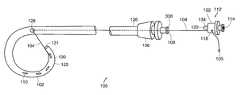
- FIG. 1Ais an illustrative diagram of a locking-pigtail catheter according to one embodiment of the invention.
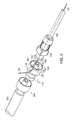
- FIG. 1Bis an illustrative perspective pulled-apart view of the male and female luer connectors of the locking-pigtail catheter shown in FIG. 1 A.
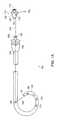
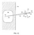
- FIG. 1Cis an illustrative diagram of the locking-pigtail catheter disposed within a patient in an unlocked position according to one embodiment of the invention.
- FIG. 1Dis an illustrative diagram of the locking-pigtail catheter disposed within a patient in a locked position according to one embodiment of the invention.
- FIG. 2is an illustrative perspective view of a locking-pigtail catheter and a connection tube according to one embodiment of the invention.
- FIG. 3Ais an illustrative perspective view of a possible arrangement of the components of the lock and the elongated flexible member of the locking-pigtail catheter shown in FIG. 1 A.
- FIG. 3Bis an illustrative perspective view of a possible arrangement of the grommet and the elongated flexible member according to another embodiment of the invention.
- FIG. 3Cis an illustrative perspective view of a possible arrangement of the grommet and the elongated flexible member according to yet another embodiment of the invention.
- FIG. 3Dis an illustrative perspective view of a possible arrangement of the grommet and the elongated flexible member according to still another embodiment of the invention.
- FIG. 3Eis an illustrative perspective view of a possible arrangement of the grommet and the elongated flexible member according to yet another embodiment of the invention.
- FIG. 3Fis an illustrative perspective pulled-apart view of the male and female luer connectors of the locking-pigtail catheter according to another embodiment of the invention.
- FIG. 3Gis an illustrative perspective pulled-apart view of the male and female luer connectors of the locking-pigtail catheter according to still another embodiment of the invention.
- FIG. 3His an illustrative perspective pulled-apart view of the male and female luer connectors of the locking-pigtail catheter according to yet another embodiment of the invention.
- FIG. 3Iis an illustrative perspective pulled-apart view of the male and female luer connectors of the locking-pigtail catheter according to still another embodiment of the invention.
- FIG. 4is an illustrative diagram in partial longitudinal cross-section of a coupled male and female luer connector according to one embodiment of the invention.
- FIG. 5is an illustrative diagram in partial longitudinal cross-section of a coupled male and female luer connector with a mechanism to prevent inadvertent decoupling according to one embodiment of the invention.
- FIG. 6is an illustrative diagram in partial longitudinal cross-section of a coupled male and female luer connector with a mechanism to prevent inadvertent decoupling according to another embodiment of the invention.
- FIG. 7Ais an illustrative diagram of a coupled male and female luer connector with a mechanism to prevent inadvertent decoupling according to yet another embodiment of the invention.
- FIG. 7Bis an illustrative diagram in partial longitudinal cross-section of the mechanism to prevent inadvertent decoupling shown in FIG. 7 A.
- FIG. 7Cis an illustrative diagram of a coupled male and female luer connector with a mechanism to prevent inadvertent decoupling according to another embodiment of the invention.
- FIG. 7Dis an illustrative diagram in partial longitudinal cross-section of the mechanism to prevent inadvertent decoupling shown in FIG. 7 C.
- FIG. 7Eis an illustrative top view diagram of the female luer connector portion of the mechanism to prevent inadvertent decoupling shown in FIG. 7 C.
- FIG. 8is an illustrative diagram in partial longitudinal cross-section of a decoupled male and female luer connector with a mechanism to prevent inadvertent decoupling according to still another embodiment of the invention.
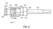
- FIG. 9is an illustrative diagram in partial longitudinal cross-section of a male and female luer connector with a mechanism to prevent inadvertent decoupling according to another embodiment of the invention.
- FIG. 10Ais an illustrative diagram of a coupled male and female luer connector with a mechanism to prevent inadvertent decoupling in an unengaged position according to another embodiment of the invention.
- FIG. 10Bis an illustrative diagram of a coupled male and female luer connector with the mechanism to prevent inadvertent decoupling shown in FIG. 10A in an engaged position.
- FIG. 10Cis an illustrative diagram of the mechanism to prevent inadvertent decoupling shown in FIGS. 10A and 10B being disengaged.
- FIG. 11Ais an illustrative diagram of a locking-pigtail catheter including a spool according to one embodiment of the invention.
- FIG. 11Bis an illustrative diagram a suture wound around the spool of the locking-pigtail catheter shown in FIG. 11 A.
- the pigtail-locking catheter 100includes an elongated body member 102 , a female luer connector 106 , a male luer connector 112 , and an elongated flexible member 104 .
- the elongated body member 102includes a plurality of apertures 110 disposed along the length of the elongated body member 102 and in the distal portion 125 , and a central lumen 131 that extends the entire length of the elongated body member 102 .
- the plurality of apertures 110provide access to the central lumen 131 to facilitate fluid flow into and/or out of the elongated body member 102 .
- the female luer connector 106includes an opening 108 and a rim 308 .
- the male luer connector 112includes an inner wall 134 and a cap 122 .
- the elongated flexible member 104is coupled to a distal portion 125 of the elongated body member 102 , extends outside of the elongated body member 102 through a distal opening 130 , and reenters the elongated body member 102 through another opening 128 disposed in a middle section of the elongated body member 102 .
- the elongated flexible member 104extends inside the elongated body member 102 through the opening 128 and along the central lumen 131 of the elongated body member 102 to the proximal end 126 of the elongated body member 102 .
- the elongated flexible member 104tied to the distal portion 125 .
- the elongated flexible member 104can be glued to the distal portion 125 or formed in the distal portion 125 .
- the elongated flexible member 104is coupled to the female luer connector 106 and extends through the elongated body member 102 to the distal portion 125 .
- the elongated flexible member 104extends outside the elongated body member 102 through the distal opening 130 and reenters the elongated body member 102 through another opening 128 disposed in a middle section of the elongated body member 102 .
- the elongated flexible member 104extends inside the elongated body member 102 from the opening 128 and along the central lumen 131 of the elongated body member 102 to the proximal end 126 of the elongated body member 102 .
- the elongated flexible member 104can be glued to the female luer connector 106 or formed in the female luer connector 106 .
- the distal portion 125 of the elongated body member 102 straightened with a stiffening stylet 166 disposed within the central lumen 131 of the elongated body member 102is inserted into a patient's bladder, for example, over a guidewire 168 .
- the stiffening stylet 166 and the guidewire 168are removed from the patient's body leaving the distal portion 125 of the elongated body member 102 disposed within the patient's bladder.
- the male luer connector 112is decoupled from the female luer connector 106 .
- the elongated flexible member 104is pulled through a channel 118 in the male luer connector 112 to draw the distal portion 125 of the elongated body member toward the proximal portion 126 of the elongated body member to form a loop in the elongated body portion 102 .
- the male luer connector 112is moved toward the female luer connector 106 until the male luer connector 112 engages the female luer connector 106 .
- an inner wall 134 of the male luer connector 112is inserted into an opening 108 of the female luer connector 106 .
- the elongated flexible member 104is compressed between the rim 308 of the opening 108 and the cap 122 of the male luer connector 112 thereby locking the elongated flexible member 104 in place and locking the distal portion 125 of the elongated body member 102 in the looped position.
- the female luer connector 106is coupled to the proximal portion 126 of the elongated body member 102 and includes a central passageway that extends therethrough which is coaxial with the central lumen 131 of the elongated body member 102 .
- the elongated flexible member 104extends through the central passageway of female luer connector 106 and out of a proximal opening 108 .
- the elongated flexible member 104is a suture thread made of nylon or other similar material of comparable strength.
- the elongated flexible member 104can be a thread or a flexible metal wire.
- the male luer connector 112includes an inner wall 134 defining a central passageway 120 that extends therethrough, a cap 122 defining a space 132 between the inner wall 134 , and a channel 118 located in a wall of the cap 120 .
- the elongated flexible member 104extends into the space 132 of the male luer connector 112 and exits through the channel 118 .
- the elongated flexible member 104includes a knot 105 disposed at the proximal end of the elongated flexible member 104 to prevent the elongated flexible member 104 from sliding out of the channel 118 or the male luer connector 112 from being loose or lost.
- the elongated flexible member 104slides through the channel 118 and allows the distal portion 125 to be drawn toward the proximal portion 126 to form a loop in the distal portion 125 .
- the male luer connector 112is moved toward the female luer connector 106 until the male luer connector 112 engages the female luer connector 106 .
- the inner wall 134is inserted into the opening 108 of the female luer connector 106 with the central passageway 120 being coaxial with the central passageway in female luer connector 106 .
- the elongated flexible member 104is compressed between the rim 308 of the opening 108 and the cap 122 thereby locking the elongated flexible member 104 in place and locking the distal portion 125 of the elongated body member 102 in the pigtail position.
- the elongated flexible member 104does not interfere with the seal between the male luer connector 112 and the female luer connector 106 when these two parts are coupled together and does not cause wicking along the elongated flexible member 104 and out of the catheter 100 .
- the male luer connector 112 and the female luer connector 106are made of molded bio-compatible plastic. In other embodiments, the male luer connector 112 and the female luer connector 106 are made of metal, such as surgical steel or aluminum. In still other embodiments, the male luer connector 112 and the female luer connector 106 need not be used and instead, other similar interference fit connectors can be used that will provide a seal and compress the elongated flexible member 104 .
- the luer connector, male or femaleis fitted on the elongated body member 102 by force fitting, gluing, or molding. In some embodiments, the elongated body member 102 can be made of plastic, nylon, polyethylene, ethylene-vinyl acetate co-polymer, or similar material.
- a grommet 116 made of compressible materialis placed inside the space 132 of the cap 122 surrounding the inner wall 134 .
- the grommet 116is compressed between the rim 308 of the opening 108 and the cap 122 and creates a seal between the male luer connector 112 and the female luer connector 106 .
- the elongated flexible member 104may radially extend through a channel 124 in the grommet 116 .
- the grommet 116When the male luer connector 112 engages the female luer connector 106 , the grommet 116 is compressed and the grommet 116 thereafter compresses the elongated flexible member 104 (as shown in FIG. 4) thereby locking the elongated flexible member 104 in place and locking the distal portion 125 of the elongated body member 102 in the pigtail position.
- the elongated flexible member 104may also be compressed and thereby locked by the grommet 116 in a variety of ways. Referring to FIG. 3B, in one embodiment, the elongated flexible member 104 extends through the central passageway 302 of the grommet 116 and is compressed between the interior surface 310 of the grommet 116 and the exterior surface of inner wall 134 . Referring to FIG. 3C, in another embodiment, the elongated flexible member 104 extends between and is compressed by the exterior surface 312 of the grommet 116 and an interior surface 136 of the cap 122 . Referring to FIG. 3D, in still another embodiment, the elongated flexible member 104 extends longitudinally through the wall of the grommet 116 .
- the elongated flexible member 104When the grommet 116 is compressed, the elongated flexible member 104 is compressed. Referring to FIG. 3E, in yet another embodiment, the elongated flexible member 104 is compressed between the distal face 306 of the grommet 116 and the rim 308 of the female luer connector 106 .
- the grommet 116is made of latex. In other embodiments, the grommet 116 can be made of silicone or foam.
- the benefit of using the grommet 116 between the male luer connector 112 and the female luer connector 106is that a better seal is created between the male luer connector 112 and the female luer connector 106 , wicking is prevented in the case where the elongated flexible member 104 is inadvertently compressed between the male luer connector 112 and the female luer connector 106 , and the elongated flexible member 104 is held more securely thereby maintaining the loop in the distal portion 125 of the elongated body member 102 .
- the positions of the female luer connector 106 and the male luer connector 112may be reversed.
- the male luer connector 112is coupled to the proximal portion 126 of the elongated body member 102
- the female luer connector 106is releasably couplable to the male luer connector 112 .
- the elongated flexible member 104may also be compressed and thereby locked by the grommet 116 in a variety of ways as shown in FIGS. 3F, 3 G, and 3 H.
- the elongated flexible member 104exits the central passageway 120 of the male luer connector 112 through an opening 320 in the inner wall 134 .
- the elongated flexible member 104pass through the channel 124 in the grommet 116 and then passes through a passageway 322 in the female luer connector 106 .
- the male luer connector 112includes proximally a female luer portion 114 which is used to mate with a male luer connector 204 of a connection tube 202 .
- the connection tube 202is used to connect the locking-pigtail catheter 100 with a medical device such as a collecting bag, for example.
- the male luer connector 112 and the female luer connector 106are threaded and are held together when the threads 402 of the male luer connector 112 engage the threads 404 of the female luer connector 106 .
- the male luer connector 204 of connection tube 202 and the female luer portion 114 of the male luer connector 112are also similarly threaded.
- the male luer connector 204 and the female portion 114are held together when the threads 406 of the male luer connector 204 engage the threads 408 of the female luer portion 114 .
- the patientmay accidentally disengage the male luer connector 112 from the female luer connector 106 instead of disengaging the male luer connector 204 from the female portion 114 and thereby unlock the loop in the distal portion 125 and increase the risk of dislodging the catheter 100 from the body cavity.
- various safety featuresmay be incorporated into the male luer connector 112 and the female luer connector 106 and are discussed below.
- the male luer connector 112includes a cap 504 which includes one or more prongs 506 .
- the female luer connector 106includes one or more notches 502 .
- the prongs 506engage the notch 502 and prevent further rotational motion of the male luer connector 112 or the female luer connector 106 and the male luer connector 112 from being inadvertently disconnected from the female luer connector 106 .
- the male luer connector 112can only be disengaged from the female luer connector 106 when the cap 504 is squeezed radially and simultaneously at two diametrically opposed positions disposed at a ninety-degree angle from the prongs 506 thereby causing the prongs 506 to lift out of the notch 502 .
- the notch 502 and the prongs 506may extend circumferentially, and fitting and release may be done through rigorous pushing together and pulling apart.
- the male luer connector 112freely rotates in either a clockwise or counterclockwise direction.
- the cap 602includes an outside portion 608 and an inside portion 610 .
- the outside portion 608includes teeth 604 disposed on the inside proximal face and extending longitudinally.
- the inside portion 610includes teeth 606 disposed on the outside proximal face and extending longitudinally but in the opposite direction of teeth 604 .
- the outer portion 608spins freely in the opposite (loosening) direction which prevents the male luer connector 112 from being inadvertently unscrewed and disconnected from the female luer connector 106 .
- the male luer connector 112can only be disengaged from the female luer connector 106 when the cap 602 is pressed toward the female luer connector 106 and turned in the loosening direction at the same time. Pressing the cap 602 toward the female luer connector 106 causes the outer portion 608 to move toward the inner portion 610 which causes the teeth 604 to engage the teeth 606 and allows the outer portion 608 to turn the inner portion 610 in the loosening direction.
- the cap 708includes a spring-loaded slidable ratchet 702 with a spring 706 and the slidable ratchet 702 mounted over a slide 710 .
- the female luer connector 106includes teeth 704 disposed on a proximal face and extending longitudinally.
- the teeth 712 in the spring-loaded ratchet 702engage the teeth 704 and prevent the male luer connector 112 from being inadvertently unscrewed and disconnected from the female luer connector 106 .
- the male luer connector 112can only be disengaged from the female luer connector 106 when the spring-loaded ratchet 702 is pressed proximally so that the teeth 704 and 712 disengage while male luer connector 112 is turned.
- the cap 718includes a spring-loaded slidable ratchet 702 with a spring 706 and the slidable ratchet 702 mounted over a slide 710 .
- the female luer connector 106includes holes (or notches) 716 disposed on a proximal face. When the male luer connector 112 and the female luer connector 106 engage each other by screwing them together, the pin 714 in the spring-loaded ratchet 702 engages one of the holes 716 and prevents the male luer connector 112 from being inadvertently unscrewed and disconnected from the female luer connector 106 .
- the male luer connector 112can only be disengaged from the female luer connector 106 when the spring-loaded ratchet 702 is pressed proximally so that the pin 714 disengages from one of the holes 716 while male luer connector 112 is turned.
- the cap 808includes teeth 804
- the female luer connector 106includes a flexible but resilient ratchet 802 which includes a tongue 810 , a landing 812 , and a pivot 814 .
- the tongue 810engages the teeth 804 and prevents the male luer connector 112 from being inadvertently unscrewed and disconnected from the female luer connector 106 .
- the male luer connector 112can only be disengaged from the female luer connector 106 when the landing 812 is pressed down radially thereby causing the tongue 810 to raise (outwardly via pivot 814 ) and then turning the male luer connector 112 .
- the female luer connector 106includes right-hand threads 906 and the female portion 114 of the male luer connector 112 includes left-hand threads 904 .
- the male luer connector 112 and the female luer connector 106engage each other by screwing together in one direction, and the male luer connector 204 on the connection tube 202 and the female portion 114 engage each other by screwing together in the opposite direction.
- connection tube 202When the connection tube 202 is disconnected from the female portion 114 of the male luer connector 112 , the male luer connector 204 is turned in a direction that tightens the connection between the male luer connector 112 and the female luer connector 106 , thus preventing the male luer connector 112 from being inadvertently unscrewed and disconnected from the female luer connector 106 and releasing the elongated flexible member 104 .
- the female luer connector 106includes a rotatable connector 910 coupled to the proximal portion 126 of the elongated body member 102 .
- the rotatable connector 910includes a first rotating portion 912 , a second rotating portion 914 coaxial with the first rotating portion 912 , and rotation point 916 coaxial with rotating portions 912 and 914 .
- Rotating portion 912 and 914are independently rotatable in both the clockwise and counterclockwise directions.
- the male luer connector 112 and the female luer connector 106are coupled together by screwing the male luer connector 112 to the female luer connector 106 while holding the rotating portion 912 .
- the male luer connector 112 and the female luer connector 106will rotate freely about the rotating point 916 ,
- the male luer connector 112can only be disengaged from the female luer connector 106 by holding the rotating portion 912 while unscrewing the male luer connector 112 . Inadvertently holding any other portion besides rotating portion 912 will prevent decoupling of the male luer connector 112 and the female luer connector 106 .
- the cap 1010includes teeth 1002 extending longitudinally from a distal face, and the female luer connector 106 includes a compressible member 1004 which includes teeth 1006 .
- the teeth 1002engage the teeth 1006 and prevent the male luer connector 112 from being inadvertently unscrewed and disconnected from the female luer connector 106 .
- the male luer connector 112can only be disengaged from the female luer connector 106 when the compressible member 1004 is compressed in a direction indicated by arrow 1008 . Compressing the compressible member 1004 causes the teeth 1002 to disengage the teeth 1006 and allows the male luer connector 112 and the female luer connector 106 to be unscrewing.
- other safety locking mechanismscan be used to prevent the male luer connector 112 from being inadvertently unscrewed and disconnected from the female luer connector 106 and releasing the elongated flexible member 104 .
- all the components of the safety locking mechanisms previously described above that are part of the male luer connector 112can be instead part of the female luer connector 106 .
- all the components of the safety locking mechanisms that are part of the female luer connector 106can be instead part of the male luer connector 112 .
- a stopcock valveis connected to and located between the connection tube 202 and the female portion 114 of the male luer connector 112 .
- the stopcock valveis used to prevent leaking from the locking-pigtail catheter 100 when the connection tube 202 is disconnected from the female portion 114 or from a medical device.
- the male luer connector 112includes a spool 1102 for winding any excess elongated flexible member 104 extending out of the channel 118 of the male luer connector 112 when the male luer connector 112 is coupled to the female luer connector 106 .
- the end 1104 of the elongated flexible member 104is coupled to spool 1102 .
- the spool 1102is turned, the elongated flexible member 104 is wound around the spool 1102 .
- the spool 1102can include a ratchet which prevents the spool 1102 from unwinding unless the ratchet is released, by pushing or pulling the spool 1102 longitudinally, for example.
- the spool 1102may be a circumferential groove disposed in the male luer connector 112 with a slit in the side of the groove to secure the end 1104 of the elongated flexible member 104 .
- the female luer connector 106includes a valve disposed in the central passageway of the female luer connector 106 .
- the valveis closed when the male luer connector 112 is decoupled from the female luer connector 106 .
- the inner wall 134is inserted into the opening 108 of the female luer connector 106 thereby opening the valve disposed in the central passageway in female luer connector 106 .
Landscapes
- Health & Medical Sciences (AREA)
- Life Sciences & Earth Sciences (AREA)
- Biophysics (AREA)
- Pulmonology (AREA)
- Engineering & Computer Science (AREA)
- Anesthesiology (AREA)
- Biomedical Technology (AREA)
- Heart & Thoracic Surgery (AREA)
- Hematology (AREA)
- Animal Behavior & Ethology (AREA)
- General Health & Medical Sciences (AREA)
- Public Health (AREA)
- Veterinary Medicine (AREA)
- Infusion, Injection, And Reservoir Apparatuses (AREA)
- Media Introduction/Drainage Providing Device (AREA)
- External Artificial Organs (AREA)
Abstract
Description
This claims priority to and the benefit of Provisional U.S. patent application Ser. No. 60/195,931 filed Apr. 10, 2000, the entirety of which is hereby incorporated by reference.
The invention relates generally to catheters and more particularly to pigtail locking catheters.
Kidney catheterization and bladder catheterization are medical procedures that permit drainage of the kidney or bladder after surgery or when the urinary system is blocked by an obstruction. Catheters designed for draining the bladder can be inserted percutaneously by first piercing the lower abdominal wall with a large hypodermic needle, fitting a cannula over the needle, and then placing the catheter within the bladder. The kidney can be accessed percutaneously through the middle of the back of the patient. Catheters are also used to drain other viscera such as the abdominal cavity, the stomach, and the biliary system.
To ensure drainage and inhibit movement of the catheter from its placement in a kidney or bladder, a catheter with a pigtail loop at its distal end is often used. After the catheter is inserted into the kidney or bladder, the pigtail loop is formed at a distal section of the catheter by pulling on a proximal end of a suture. The suture extends through and out of the catheter. A proximal portion of the suture is then secured to hold it in place and retain the loop shape at the distal section of the catheter.
One such lockable pigtail loop catheter was available from Boston Scientific Corporation of Natick, Mass. under the name “Microvasive Special Percutaneous Nephrostomy Catheters.” With the Special Percutaneous Nephrostomy Catheter, the suture was secured by screwing a separate, loose cap onto the proximal end of the catheter, thereby trapping the suture and securing it. Other locking arrangements also are known.
The invention relates generally to locking catheters and methods for using such locking catheters. In one aspect, the invention involves a locking catheter. The locking catheter includes an elongated body member which defines a central lumen. The elongated body includes a distal portion and a proximal portion where at least a portion of the elongated body is for placement within a patient. The locking catheter further includes a first proximal member disposed at the proximal portion of the elongated body member and defines a central passageway which extends therethrough and is coaxial with the lumen. The locking catheter further includes an elongated flexible member. The elongated flexible member includes a first end and a second end. The first end is coupled to the distal portion of the elongated body member and extends through both at least a portion of the central lumen of the elongated body member and the central passageway of the first proximal member. The second end is disposed external to the elongated body member. The locking catheter further includes a second proximal member releasably couplable to the first proximal member to allow selective locking and unlocking of the elongated flexible member therebetween. The second proximal member defines a central passageway which extends therethrough and a separate channel which also extends therethrough. The elongated flexible member extends through the separate channel and is slidable therethrough to allow the distal portion of the elongated body member to be drawn toward the proximal portion of the elongated body member to form a loop in the distal portion when the first and second proximal members are decoupled. The central passageway of the second proximal member extends coaxially from the central passageway of the first proximal member and the elongated flexible member is compressed between the first and second proximal members and is non-slidable through the separate channel to secure the loop when the first and second proximal members are coupled together.
In one embodiment the locking catheter further comprises a grommet which defines a central passageway extending therethrough. The grommet is disposed between the first proximal member and the second proximal member with the central passageway of the grommet coaxial with the central passageway of the second proximal member. The grommet creates a seal between the first proximal member and the second proximal member when the first proximal member is coupled to the second proximal member.
In another embodiment, the grommet also defines a channel extending therethrough and the elongated flexible member extends through the channel of the grommet.
In still another embodiment, the first proximal member is a female luer connector and the second proximal member is a male luer connector.
In yet another embodiment, the central lumen of the elongated body member, the central passageway of the first proximal body, and the central passageway of the second proximal body are configured to receive a stylet.
In other embodiments, the elongated member comprises plastic.
In still other embodiments, the elongated member includes a plurality of apertures for allowing fluid to flow into and out of the central lumen of the elongated member.
In yet other embodiments, the first proximal member includes a valve which is open when the first proximal member is coupled to the second proximal member, and which is closed when the first proximal member is decoupled from the second proximal member.
In another embodiment, the first proximal member includes a ratchet and the second proximal member includes teeth. The ratchet engages the teeth when the second proximal member is coupled to the first proximal member and prevents the second proximal member from inadvertently decoupling from the first proximal member.
In another embodiment, the first proximal member includes one of a male and female latch and the second proximal member includes the other of a male and female latch. The male latch includes a prong and the female latch includes a notch. The male latch engages the female latch when the first proximal member is coupled to the second proximal member and prevents the first proximal member from inadvertently decoupling from the second proximal member.
In yet another embodiment, the first proximal member includes a first latch which includes a first set of teeth and the second proximal member includes a second latch which includes a second set of teeth. The first set of teeth engages the second set of teeth when the first proximal member is coupled to the second proximal member and prevents the first proximal member from inadvertently decoupling from the second proximal member.
In still another embodiment, the second proximal member includes a spool to wind the elongated flexible member therearound when the second proximal member is coupled to the first proximal member.
In yet another embodiment, the locking catheter further includes a second elongated body member which defines a central lumen extending therethrough. The elongated body member includes a first port and a second port. The first port is removably couplable to the second proximal member and extends coaxially from the central passageway of the second proximal member. The second port is connectable to a device external to the patient.
In other embodiments, the first port includes a valve for sealing the central passageway of the second proximal member when the second port is decoupled from the device external to the patient. In some embodiments, the valve is a stopcock.
In another aspect, the invention involves a method of locking a catheter in a patient. The method includes providing a locking catheter. The locking catheter includes an elongated body member which defines a central lumen. The elongated body includes a distal portion and a proximal portion where at least a portion of the elongated body member is for placement within a patient. The locking catheter further includes a first proximal member which is disposed at the proximal portion of the elongated body member and defines a central passageway which extends therethrough and is coaxial with the lumen. The locking catheter further includes an elongated flexible member which includes a first end and a second end. The first end is coupled to the distal portion of the elongated body member. The elongated flexible member extends through both at least a portion of the central lumen of the elongated body member and the central passageway of the first proximal member with the second end disposed external to the elongated body member. The locking catheter further includes a second proximal member releasably couplable to the first proximal member to allow selective locking and unlocking of the elongated flexible member therebetween. The second proximal member defines a central passageway extending therethrough and a separate channel also extending therethrough. The elongated flexible member extends through the separate channel and is slidable therethrough to allow the distal portion of the elongated body member to be drawn toward the proximal portion of the elongated body member.
The method further includes inserting at least the distal portion of the elongated body member into the patient and pulling the elongated flexible member through the separate channel of the second proximal member to draw the distal portion of the elongated body member toward the proximal portion of the elongated body member and thereby forming a loop in the distal portion. The method further includes coupling the first and second proximal members together to compress and lock the elongated flexible member and secure the loop.
In still another aspect, the invention involves a locking catheter. The locking catheter includes an elongated body member defining a central lumen and comprising a distal portion and a proximal portion, where at least a portion of the elongated body member is for placement within a patient. The locking catheter further includes a first proximal member disposed at the proximal portion of the elongated body member and defines a central passageway extending therethrough and a separate channel extending therethrough. The central passageway of the first proximal member is coaxial with the lumen. The locking catheter further includes an elongated flexible member. The elongated flexible member includes a first end and a second end. The first end is coupled to the distal portion of the elongated body member and the elongated flexible member extends through at least a portion of the central lumen of the elongated body member, the central passageway of the first proximal member, and the separate channel. The elongated flexible member is slidable through the separate channel to allow the distal portion of the elongated body member to be drawn toward the proximal portion of the elongated body member to form a loop in the distal portion, with the second end disposed external to the elongated body member. The locking catheter further comprises a second proximal member releasably couplable to the first proximal member to allow selective locking and unlocking of the elongated flexible member therebetween. The second proximal member defines a central passageway extending therethrough, and the central passageway of the second proximal member extends coaxially from the central passageway of the first proximal member. The elongated flexible member is compressed between the first and second proximal members and is non-slidable through the separate channel and secures the loop when the first and second proximal members are coupled together.
The foregoing and other objects, aspects, features, and advantages of the invention will become more apparent from the following description, the drawings, and from the claims.
In the drawings, like reference characters generally refer to the same parts throughout the different views. Also, the drawings are not necessarily to scale, emphasis instead generally being placed upon illustrating the principles of the invention.
FIG. 1A is an illustrative diagram of a locking-pigtail catheter according to one embodiment of the invention.
FIG. 1B is an illustrative perspective pulled-apart view of the male and female luer connectors of the locking-pigtail catheter shown in FIG.1A.
FIG. 1C is an illustrative diagram of the locking-pigtail catheter disposed within a patient in an unlocked position according to one embodiment of the invention.
FIG. 1D is an illustrative diagram of the locking-pigtail catheter disposed within a patient in a locked position according to one embodiment of the invention.
FIG. 2 is an illustrative perspective view of a locking-pigtail catheter and a connection tube according to one embodiment of the invention.
FIG. 3A is an illustrative perspective view of a possible arrangement of the components of the lock and the elongated flexible member of the locking-pigtail catheter shown in FIG.1A.
FIG. 3B is an illustrative perspective view of a possible arrangement of the grommet and the elongated flexible member according to another embodiment of the invention.
FIG. 3C is an illustrative perspective view of a possible arrangement of the grommet and the elongated flexible member according to yet another embodiment of the invention.
FIG. 3D is an illustrative perspective view of a possible arrangement of the grommet and the elongated flexible member according to still another embodiment of the invention.
FIG. 3E is an illustrative perspective view of a possible arrangement of the grommet and the elongated flexible member according to yet another embodiment of the invention.
FIG. 3F is an illustrative perspective pulled-apart view of the male and female luer connectors of the locking-pigtail catheter according to another embodiment of the invention.
FIG. 3G is an illustrative perspective pulled-apart view of the male and female luer connectors of the locking-pigtail catheter according to still another embodiment of the invention.
FIG. 3H is an illustrative perspective pulled-apart view of the male and female luer connectors of the locking-pigtail catheter according to yet another embodiment of the invention.
FIG. 3I is an illustrative perspective pulled-apart view of the male and female luer connectors of the locking-pigtail catheter according to still another embodiment of the invention.
FIG. 4 is an illustrative diagram in partial longitudinal cross-section of a coupled male and female luer connector according to one embodiment of the invention.
FIG. 5 is an illustrative diagram in partial longitudinal cross-section of a coupled male and female luer connector with a mechanism to prevent inadvertent decoupling according to one embodiment of the invention.
FIG. 6 is an illustrative diagram in partial longitudinal cross-section of a coupled male and female luer connector with a mechanism to prevent inadvertent decoupling according to another embodiment of the invention.
FIG. 7A is an illustrative diagram of a coupled male and female luer connector with a mechanism to prevent inadvertent decoupling according to yet another embodiment of the invention.
FIG. 7B is an illustrative diagram in partial longitudinal cross-section of the mechanism to prevent inadvertent decoupling shown in FIG.7A.
FIG. 7C is an illustrative diagram of a coupled male and female luer connector with a mechanism to prevent inadvertent decoupling according to another embodiment of the invention.
FIG. 7D is an illustrative diagram in partial longitudinal cross-section of the mechanism to prevent inadvertent decoupling shown in FIG.7C.
FIG. 7E is an illustrative top view diagram of the female luer connector portion of the mechanism to prevent inadvertent decoupling shown in FIG.7C.
FIG. 8 is an illustrative diagram in partial longitudinal cross-section of a decoupled male and female luer connector with a mechanism to prevent inadvertent decoupling according to still another embodiment of the invention.
FIG. 9 is an illustrative diagram in partial longitudinal cross-section of a male and female luer connector with a mechanism to prevent inadvertent decoupling according to another embodiment of the invention.
FIG. 10A is an illustrative diagram of a coupled male and female luer connector with a mechanism to prevent inadvertent decoupling in an unengaged position according to another embodiment of the invention.
FIG. 10B is an illustrative diagram of a coupled male and female luer connector with the mechanism to prevent inadvertent decoupling shown in FIG. 10A in an engaged position.
FIG. 10C is an illustrative diagram of the mechanism to prevent inadvertent decoupling shown in FIGS. 10A and 10B being disengaged.
FIG. 11A is an illustrative diagram of a locking-pigtail catheter including a spool according to one embodiment of the invention.
FIG. 11B is an illustrative diagram a suture wound around the spool of the locking-pigtail catheter shown in FIG.11A.
The present invention is used to drain viscera such as the kidneys, bladder, abdominal cavity, the stomach, and the biliary system. Referring to FIG. 1A, FIG. 1C, and FIG1D, in one embodiment, the pigtail-lockingcatheter 100 includes anelongated body member 102, afemale luer connector 106, amale luer connector 112, and an elongatedflexible member 104. Theelongated body member 102 includes a plurality ofapertures 110 disposed along the length of theelongated body member 102 and in thedistal portion 125, and acentral lumen 131 that extends the entire length of theelongated body member 102. The plurality ofapertures 110 provide access to thecentral lumen 131 to facilitate fluid flow into and/or out of theelongated body member 102. Thefemale luer connector 106 includes anopening 108 and arim 308. Themale luer connector 112 includes aninner wall 134 and acap 122.
The elongatedflexible member 104 is coupled to adistal portion 125 of theelongated body member 102, extends outside of theelongated body member 102 through adistal opening 130, and reenters theelongated body member 102 through anotheropening 128 disposed in a middle section of theelongated body member 102. The elongatedflexible member 104 extends inside theelongated body member 102 through theopening 128 and along thecentral lumen 131 of theelongated body member 102 to theproximal end 126 of theelongated body member 102. In one embodiment, the elongatedflexible member 104 tied to thedistal portion 125. In other embodiments, the elongatedflexible member 104 can be glued to thedistal portion 125 or formed in thedistal portion 125.
In another embodiment, the elongatedflexible member 104 is coupled to thefemale luer connector 106 and extends through theelongated body member 102 to thedistal portion 125. The elongatedflexible member 104 extends outside theelongated body member 102 through thedistal opening 130 and reenters theelongated body member 102 through anotheropening 128 disposed in a middle section of theelongated body member 102. The elongatedflexible member 104 extends inside theelongated body member 102 from theopening 128 and along thecentral lumen 131 of theelongated body member 102 to theproximal end 126 of theelongated body member 102. In other embodiments, the elongatedflexible member 104 can be glued to thefemale luer connector 106 or formed in thefemale luer connector 106.
Referring to FIGS. 1C and 1D, thedistal portion 125 of theelongated body member 102 straightened with a stiffeningstylet 166 disposed within thecentral lumen 131 of theelongated body member 102 is inserted into a patient's bladder, for example, over aguidewire 168. The stiffeningstylet 166 and theguidewire 168 are removed from the patient's body leaving thedistal portion 125 of theelongated body member 102 disposed within the patient's bladder. Themale luer connector 112 is decoupled from thefemale luer connector 106. The elongatedflexible member 104 is pulled through achannel 118 in themale luer connector 112 to draw thedistal portion 125 of the elongated body member toward theproximal portion 126 of the elongated body member to form a loop in theelongated body portion 102. As the elongatedflexible member 104 is pulled through thechannel 118, themale luer connector 112 is moved toward thefemale luer connector 106 until themale luer connector 112 engages thefemale luer connector 106. When themale luer connector 112 engages thefemale luer connector 106, aninner wall 134 of themale luer connector 112 is inserted into anopening 108 of thefemale luer connector 106. The elongatedflexible member 104 is compressed between therim 308 of theopening 108 and thecap 122 of themale luer connector 112 thereby locking the elongatedflexible member 104 in place and locking thedistal portion 125 of theelongated body member 102 in the looped position.
Referring to FIGS. 1A,1B, and2, thefemale luer connector 106 is coupled to theproximal portion 126 of theelongated body member 102 and includes a central passageway that extends therethrough which is coaxial with thecentral lumen 131 of theelongated body member 102. The elongatedflexible member 104 extends through the central passageway offemale luer connector 106 and out of aproximal opening 108. In one embodiment, the elongatedflexible member 104 is a suture thread made of nylon or other similar material of comparable strength. In other embodiments, the elongatedflexible member 104 can be a thread or a flexible metal wire.
Themale luer connector 112 includes aninner wall 134 defining acentral passageway 120 that extends therethrough, acap 122 defining aspace 132 between theinner wall 134, and achannel 118 located in a wall of thecap 120. The elongatedflexible member 104 extends into thespace 132 of themale luer connector 112 and exits through thechannel 118. The elongatedflexible member 104 includes aknot 105 disposed at the proximal end of the elongatedflexible member 104 to prevent the elongatedflexible member 104 from sliding out of thechannel 118 or themale luer connector 112 from being loose or lost. The elongatedflexible member 104 slides through thechannel 118 and allows thedistal portion 125 to be drawn toward theproximal portion 126 to form a loop in thedistal portion 125. As the elongatedflexible member 104 is drawn through thechannel 118, themale luer connector 112 is moved toward thefemale luer connector 106 until themale luer connector 112 engages thefemale luer connector 106. When themale luer connector 112 engages thefemale luer connector 106, theinner wall 134 is inserted into theopening 108 of thefemale luer connector 106 with thecentral passageway 120 being coaxial with the central passageway infemale luer connector 106. The elongatedflexible member 104 is compressed between therim 308 of theopening 108 and thecap 122 thereby locking the elongatedflexible member 104 in place and locking thedistal portion 125 of theelongated body member 102 in the pigtail position. By compressing the elongatedflexible member 104 between therim 308 of theopening 108 and theinner wall 134, the elongatedflexible member 104 does not interfere with the seal between themale luer connector 112 and thefemale luer connector 106 when these two parts are coupled together and does not cause wicking along the elongatedflexible member 104 and out of thecatheter 100.
In one embodiment, themale luer connector 112 and thefemale luer connector 106 are made of molded bio-compatible plastic. In other embodiments, themale luer connector 112 and thefemale luer connector 106 are made of metal, such as surgical steel or aluminum. In still other embodiments, themale luer connector 112 and thefemale luer connector 106 need not be used and instead, other similar interference fit connectors can be used that will provide a seal and compress the elongatedflexible member 104. The luer connector, male or female, is fitted on theelongated body member 102 by force fitting, gluing, or molding. In some embodiments, theelongated body member 102 can be made of plastic, nylon, polyethylene, ethylene-vinyl acetate co-polymer, or similar material.
Referring to FIGS. 1B,2, and3A, in another embodiment, agrommet 116 made of compressible material is placed inside thespace 132 of thecap 122 surrounding theinner wall 134. When themale luer connector 112 engages thefemale luer connector 106, thegrommet 116 is compressed between therim 308 of theopening 108 and thecap 122 and creates a seal between themale luer connector 112 and thefemale luer connector 106. As shown in FIGS. 1B and 3A, the elongatedflexible member 104 may radially extend through achannel 124 in thegrommet 116. When themale luer connector 112 engages thefemale luer connector 106, thegrommet 116 is compressed and thegrommet 116 thereafter compresses the elongated flexible member104 (as shown in FIG. 4) thereby locking the elongatedflexible member 104 in place and locking thedistal portion 125 of theelongated body member 102 in the pigtail position.
The elongatedflexible member 104 may also be compressed and thereby locked by thegrommet 116 in a variety of ways. Referring to FIG. 3B, in one embodiment, the elongatedflexible member 104 extends through thecentral passageway 302 of thegrommet 116 and is compressed between theinterior surface 310 of thegrommet 116 and the exterior surface ofinner wall 134. Referring to FIG. 3C, in another embodiment, the elongatedflexible member 104 extends between and is compressed by theexterior surface 312 of thegrommet 116 and aninterior surface 136 of thecap 122. Referring to FIG. 3D, in still another embodiment, the elongatedflexible member 104 extends longitudinally through the wall of thegrommet 116. When thegrommet 116 is compressed, the elongatedflexible member 104 is compressed. Referring to FIG. 3E, in yet another embodiment, the elongatedflexible member 104 is compressed between thedistal face 306 of thegrommet 116 and therim 308 of thefemale luer connector 106. In one embodiment, thegrommet 116 is made of latex. In other embodiments, thegrommet 116 can be made of silicone or foam.
The benefit of using thegrommet 116 between themale luer connector 112 and thefemale luer connector 106 is that a better seal is created between themale luer connector 112 and thefemale luer connector 106, wicking is prevented in the case where the elongatedflexible member 104 is inadvertently compressed between themale luer connector 112 and thefemale luer connector 106, and the elongatedflexible member 104 is held more securely thereby maintaining the loop in thedistal portion 125 of theelongated body member 102.
Referring to FIGS. 3F,3G, and3H, the positions of thefemale luer connector 106 and themale luer connector 112 may be reversed. In such embodiments, themale luer connector 112 is coupled to theproximal portion 126 of theelongated body member 102, and thefemale luer connector 106 is releasably couplable to themale luer connector 112. The elongatedflexible member 104 may also be compressed and thereby locked by thegrommet 116 in a variety of ways as shown in FIGS. 3F,3G, and3H.
Referring to FIG. 3I, in another embodiment, the elongatedflexible member 104 exits thecentral passageway 120 of themale luer connector 112 through anopening 320 in theinner wall 134. The elongatedflexible member 104 pass through thechannel 124 in thegrommet 116 and then passes through apassageway 322 in thefemale luer connector 106.
Referring again to FIGS. 1A and 2, themale luer connector 112 includes proximally afemale luer portion 114 which is used to mate with amale luer connector 204 of aconnection tube 202. Theconnection tube 202 is used to connect the locking-pigtail catheter 100 with a medical device such as a collecting bag, for example.
Referring to FIG. 4, typically, themale luer connector 112 and thefemale luer connector 106 are threaded and are held together when thethreads 402 of themale luer connector 112 engage thethreads 404 of thefemale luer connector 106. Themale luer connector 204 ofconnection tube 202 and thefemale luer portion 114 of themale luer connector 112 are also similarly threaded. Themale luer connector 204 and thefemale portion 114 are held together when thethreads 406 of themale luer connector 204 engage thethreads 408 of thefemale luer portion 114. When a patient attempts to disconnect theconnection tube 202 from the locking-pigtail catheter 100, the patient may accidentally disengage themale luer connector 112 from thefemale luer connector 106 instead of disengaging themale luer connector 204 from thefemale portion 114 and thereby unlock the loop in thedistal portion 125 and increase the risk of dislodging thecatheter 100 from the body cavity. To prevent themale luer connector 112 from being inadvertently disengaged from thefemale luer 106, various safety features may be incorporated into themale luer connector 112 and thefemale luer connector 106 and are discussed below.
Referring to FIG. 5, in one embodiment themale luer connector 112 includes acap 504 which includes one ormore prongs 506. Thefemale luer connector 106 includes one ormore notches 502. When themale luer connector 112 and thefemale luer connector 106 engage each other (by pushing or screwing them together, for example), theprongs 506 engage thenotch 502 and prevent further rotational motion of themale luer connector 112 or thefemale luer connector 106 and themale luer connector 112 from being inadvertently disconnected from thefemale luer connector 106. Themale luer connector 112 can only be disengaged from thefemale luer connector 106 when thecap 504 is squeezed radially and simultaneously at two diametrically opposed positions disposed at a ninety-degree angle from theprongs 506 thereby causing theprongs 506 to lift out of thenotch 502. Alternatively, thenotch 502 and theprongs 506 may extend circumferentially, and fitting and release may be done through rigorous pushing together and pulling apart. When thenotch 502 is circumferential groove, themale luer connector 112 freely rotates in either a clockwise or counterclockwise direction.
Referring to FIG. 6, in another embodiment, the cap602 includes anoutside portion 608 and aninside portion 610. Theoutside portion 608 includesteeth 604 disposed on the inside proximal face and extending longitudinally. Theinside portion 610 includesteeth 606 disposed on the outside proximal face and extending longitudinally but in the opposite direction ofteeth 604. When themale luer connector 112 and thefemale luer connector 106 engage each other by screwing them together, theteeth 604 engage theteeth 606 and allow theouter portion 608 to turn theinner portion 610 and thereby tighten the coupling of themale luer connector 112 and thefemale luer connector 106. Theouter portion 608 spins freely in the opposite (loosening) direction which prevents themale luer connector 112 from being inadvertently unscrewed and disconnected from thefemale luer connector 106. Themale luer connector 112 can only be disengaged from thefemale luer connector 106 when the cap602 is pressed toward thefemale luer connector 106 and turned in the loosening direction at the same time. Pressing the cap602 toward thefemale luer connector 106 causes theouter portion 608 to move toward theinner portion 610 which causes theteeth 604 to engage theteeth 606 and allows theouter portion 608 to turn theinner portion 610 in the loosening direction.
Referring to FIGS. 7A and 7B, in still another embodiment, the cap708 includes a spring-loadedslidable ratchet 702 with aspring 706 and theslidable ratchet 702 mounted over aslide 710. Thefemale luer connector 106 includesteeth 704 disposed on a proximal face and extending longitudinally. When themale luer connector 112 and thefemale luer connector 106 engage each other by screwing them together, theteeth 712 in the spring-loadedratchet 702 engage theteeth 704 and prevent themale luer connector 112 from being inadvertently unscrewed and disconnected from thefemale luer connector 106. Themale luer connector 112 can only be disengaged from thefemale luer connector 106 when the spring-loadedratchet 702 is pressed proximally so that theteeth male luer connector 112 is turned.
Referring to FIGS. 7C,7D, and7E, in still another embodiment, thecap 718 includes a spring-loadedslidable ratchet 702 with aspring 706 and theslidable ratchet 702 mounted over aslide 710. Thefemale luer connector 106 includes holes (or notches)716 disposed on a proximal face. When themale luer connector 112 and thefemale luer connector 106 engage each other by screwing them together, thepin 714 in the spring-loadedratchet 702 engages one of theholes 716 and prevents themale luer connector 112 from being inadvertently unscrewed and disconnected from thefemale luer connector 106. Themale luer connector 112 can only be disengaged from thefemale luer connector 106 when the spring-loadedratchet 702 is pressed proximally so that thepin 714 disengages from one of theholes 716 whilemale luer connector 112 is turned.
Referring to FIG. 8, in yet another embodiment, thecap 808 includesteeth 804, and thefemale luer connector 106 includes a flexible butresilient ratchet 802 which includes atongue 810, alanding 812, and apivot 814. When themale luer connector 112 and thefemale luer connector 106 engage each other by screwing them together, thetongue 810 engages theteeth 804 and prevents themale luer connector 112 from being inadvertently unscrewed and disconnected from thefemale luer connector 106. Themale luer connector 112 can only be disengaged from thefemale luer connector 106 when thelanding 812 is pressed down radially thereby causing thetongue 810 to raise (outwardly via pivot814) and then turning themale luer connector 112.
Referring to FIG. 9, in yet another embodiment, thefemale luer connector 106 includes right-hand threads 906 and thefemale portion 114 of themale luer connector 112 includes left-hand threads 904. Themale luer connector 112 and thefemale luer connector 106 engage each other by screwing together in one direction, and themale luer connector 204 on theconnection tube 202 and thefemale portion 114 engage each other by screwing together in the opposite direction. When theconnection tube 202 is disconnected from thefemale portion 114 of themale luer connector 112, themale luer connector 204 is turned in a direction that tightens the connection between themale luer connector 112 and thefemale luer connector 106, thus preventing themale luer connector 112 from being inadvertently unscrewed and disconnected from thefemale luer connector 106 and releasing the elongatedflexible member 104.
In another embodiment, thefemale luer connector 106 includes a rotatable connector910 coupled to theproximal portion 126 of theelongated body member 102. The rotatable connector910 includes a firstrotating portion 912, a secondrotating portion 914 coaxial with the firstrotating portion 912, androtation point 916 coaxial withrotating portions portion male luer connector 112 and thefemale luer connector 106 are coupled together by screwing themale luer connector 112 to thefemale luer connector 106 while holding therotating portion 912. After themale luer connector 112 and thefemale luer connector 106 are coupled together, themale luer connector 112 and thefemale luer connector 106 will rotate freely about therotating point 916, Themale luer connector 112 can only be disengaged from thefemale luer connector 106 by holding therotating portion 912 while unscrewing themale luer connector 112. Inadvertently holding any other portion besides rotatingportion 912 will prevent decoupling of themale luer connector 112 and thefemale luer connector 106.
Referring to FIGS. 10A,10B, and10C, in another embodiment, Thecap 1010 includesteeth 1002 extending longitudinally from a distal face, and thefemale luer connector 106 includes acompressible member 1004 which includesteeth 1006. When themale luer connector 112 and thefemale luer connector 106 engage each other by screwing them together, theteeth 1002 engage theteeth 1006 and prevent themale luer connector 112 from being inadvertently unscrewed and disconnected from thefemale luer connector 106. Themale luer connector 112 can only be disengaged from thefemale luer connector 106 when thecompressible member 1004 is compressed in a direction indicated byarrow 1008. Compressing thecompressible member 1004 causes theteeth 1002 to disengage theteeth 1006 and allows themale luer connector 112 and thefemale luer connector 106 to be unscrewing.
In other embodiments, other safety locking mechanisms can be used to prevent themale luer connector 112 from being inadvertently unscrewed and disconnected from thefemale luer connector 106 and releasing the elongatedflexible member 104. Additionally, all the components of the safety locking mechanisms previously described above that are part of themale luer connector 112 can be instead part of thefemale luer connector 106. Likewise, all the components of the safety locking mechanisms that are part of thefemale luer connector 106 can be instead part of themale luer connector 112.
In another embodiment, a stopcock valve is connected to and located between theconnection tube 202 and thefemale portion 114 of themale luer connector 112. The stopcock valve is used to prevent leaking from the locking-pigtail catheter 100 when theconnection tube 202 is disconnected from thefemale portion 114 or from a medical device.
Referring to FIGS. 11A and 11B, in still another embodiment, themale luer connector 112 includes aspool 1102 for winding any excess elongatedflexible member 104 extending out of thechannel 118 of themale luer connector 112 when themale luer connector 112 is coupled to thefemale luer connector 106. Theend 1104 of the elongatedflexible member 104 is coupled tospool 1102. As thespool 1102 is turned, the elongatedflexible member 104 is wound around thespool 1102. Additionally, thespool 1102 can include a ratchet which prevents thespool 1102 from unwinding unless the ratchet is released, by pushing or pulling thespool 1102 longitudinally, for example. In another embodiment, thespool 1102 may be a circumferential groove disposed in themale luer connector 112 with a slit in the side of the groove to secure theend 1104 of the elongatedflexible member 104.
In yet another embodiment, thefemale luer connector 106 includes a valve disposed in the central passageway of thefemale luer connector 106. The valve is closed when themale luer connector 112 is decoupled from thefemale luer connector 106. When themale luer connector 112 engages thefemale luer connector 106, theinner wall 134 is inserted into theopening 108 of thefemale luer connector 106 thereby opening the valve disposed in the central passageway infemale luer connector 106.
Variations, modifications, and other implementations of what is described herein may occur to those of ordinary skill in the art without departing from the spirit and scope of the invention. Accordingly, the invention is not to be defined only by the preceding illustrative description.
Claims (17)
1. A locking catheter, comprising:
an elongated body member defining a central lumen and comprising a distal portion and a proximal portion, at least a portion of the elongated body member for placement within a patient;
a first proximal member disposed at the proximal portion of the elongated body member and defining a central passageway extending therethrough and coaxial with the lumen;
an elongated flexible member comprising a first end and a second end, the first end coupled to the distal portion of the elongated body member, the elongated flexible member extending through both at least a portion of the central lumen of the elongated body member and the central passageway of the first proximal member with the second end disposed external to the elongated body member; and
a second proximal member releasably couplable to the first proximal member to allow selective locking and unlocking of the elongated flexible member therebetween, the second proximal member defining a central passageway extending therethrough and a separate channel extending therethrough, the elongated flexible member extending through the separate channel and being slidable therethrough to allow the distal portion of the elongated body member to be drawn toward the proximal portion of the elongated body member to form a loop in the distal portion when the first and second proximal members are decoupled, the central passageway of the second proximal member extending coaxially from the central passageway of the first proximal member and the elongated flexible member being compressed between the first and second proximal members and non-slidable through the separate channel to secure the loop when the first and second proximal members are coupled together.
2. The locking catheter ofclaim 1 , further comprising a grommet defining a central passageway extending therethrough, the grommet disposed between the first proximal member and the second proximal member with the central passageway of the grommet coaxial with the central passageway of the second proximal member and creating a seal between the first proximal member and the second proximal member when the first proximal member is coupled to the second proximal member.
3. The locking catheter ofclaim 2 , wherein the grommet also defines a channel extending therethrough and wherein the elongated flexible member extends through the channel of the grommet.
4. The locking catheter ofclaim 1 , wherein the first proximal member is a female luer connector and the second proximal member is a male luer connector.
5. The locking catheter ofclaim 1 , wherein central lumen of the elongated body member, the central passageway of the first proximal body, and the central passageway of the second proximal body are configured to receive a stylet.
6. The locking catheter ofclaim 1 , wherein the elongated member comprises plastic.
7. The locking catheter ofclaim 1 , wherein the elongated member comprises a plurality of apertures for allowing fluid into and out of the central lumen of the elongated member.
8. The locking catheter ofclaim 1 , wherein the first proximal member comprises a valve, the valve being open when the first proximal member is coupled to the second proximal member, and the valve being closed when the first proximal member is decoupled from the second proximal member.
9. The locking catheter ofclaim 1 , wherein the first proximal member comprises a ratchet and the second proximal member comprises teeth, the ratchet engaging the teeth when the second proximal member is coupled to the first proximal member and thereby preventing the second proximal member from inadvertently decoupling from the first proximal member.
10. The locking catheter ofclaim 1 , wherein the first proximal member comprises one of a male and female latch and the second proximal member comprises the other of a male and female latch, the male latch comprising a prong, the female latch comprising a notch, the male latch engaging the female latch when the first proximal member is coupled to the second proximal member and thereby preventing the first proximal member from inadvertently decoupling from the second proximal member.
11. The locking catheter ofclaim 1 , wherein the first proximal member comprises a first latch including a first set of teeth and the second proximal member comprises a second latch including a second set of teeth, the first set of teeth engaging the second set of teeth when the first proximal member is coupled to the second proximal member thereby preventing the first proximal member from inadvertently decoupling from the second proximal member.
12. The locking catheter ofclaim 1 , wherein the second proximal member comprises a spool to wind the elongated flexible member therearound when the second proximal member is coupled to the first proximal member.
13. The locking catheter ofclaim 1 , further comprising a second elongated body member defining a central lumen extending therethrough, the elongated body member comprising a first port and a second port, the first port removably couplable to the second proximal member and extending coaxially from the central passageway of the second proximal member, the second port for connecting to a device external to the patient.
14. The locking catheter ofclaim 13 , wherein the first port comprises a valve for sealing the central passageway of the second proximal member when the second port is decoupled from the device external to the patient.
15. The locking catheter ofclaim 14 , wherein the valve comprises a stopcock.
16. A method of locking a catheter in a patient, comprising:
providing a locking catheter comprising:
an elongated body member defining a central lumen and comprising a distal portion and a proximal portion, at least a portion of the elongated body member for placement within a patient,
a first proximal member disposed at the proximal portion of the elongated body member and defining a central passageway extending therethrough and coaxial with the lumen,
an elongated flexible member comprising a first end and a second end, the first end coupled to the distal portion of the elongated body member, the elongated flexible member extending through both at least a portion of the central lumen of the elongated body member and the central passageway of the first proximal member with the second end disposed external to the elongated body member, and
a second proximal member releasably couplable to the first proximal member to allow selective locking and unlocking of the elongated flexible member therebetween, the second proximal member defining a central passageway extending therethrough and a separate channel extending therethrough, the elongated flexible member extending through the separate channel and being slidable therethrough to allow the distal portion of the elongated body member to be drawn toward the proximal portion of the elongated body member;
inserting at least the distal portion of the elongated body member into the patient;
pulling the elongated flexible member through the separate channel of the second proximal member to draw the distal portion of the elongated body member toward the proximal portion of the elongated body member thereby forming a loop in the distal portion; and
coupling the first and second proximal members together to compress and lock the elongated flexible member and secure the loop.
17. A locking catheter, comprising:
an elongated body member defining a central lumen and comprising a distal portion and a proximal portion, at least a portion of the elongated body member for placement within a patient;
a first proximal member disposed at the proximal portion of the elongated body member and defining a central passageway extending therethrough and a separate channel extending therethrough, the central passageway being coaxial with the lumen;
an elongated flexible member comprising a first end and a second end, the first end coupled to the distal portion of the elongated body member, the elongated flexible member extending through at least a portion of the central lumen of the elongated body member, the central passageway of the first proximal member, and the separate channel, and being slidable through the separate channel to allow the distal portion of the elongated body member to be drawn toward the proximal portion of the elongated body member to form a loop in the distal portion, with the second end disposed external to the elongated body member; and
a second proximal member releasably couplable to the first proximal member to allow selective locking and unlocking of the elongated flexible member therebetween, the second proximal member defining a central passageway extending therethrough, the central passageway of the second proximal member extending coaxially from the central passageway of the first proximal member and the elongated flexible member being compressed between the first and second proximal members and non-slidable through the separate channel to secure the loop when the first and second proximal members are coupled together.
Priority Applications (1)
| Application Number | Priority Date | Filing Date | Title |
|---|---|---|---|
| US09/829,731US6699233B2 (en) | 2000-04-10 | 2001-04-10 | Locking catheter |
Applications Claiming Priority (2)
| Application Number | Priority Date | Filing Date | Title |
|---|---|---|---|
| US19593100P | 2000-04-10 | 2000-04-10 | |
| US09/829,731US6699233B2 (en) | 2000-04-10 | 2001-04-10 | Locking catheter |
Publications (2)
| Publication Number | Publication Date |
|---|---|
| US20010049490A1 US20010049490A1 (en) | 2001-12-06 |
| US6699233B2true US6699233B2 (en) | 2004-03-02 |
Family
ID=22723419
Family Applications (1)
| Application Number | Title | Priority Date | Filing Date |
|---|---|---|---|
| US09/829,731Expired - LifetimeUS6699233B2 (en) | 2000-04-10 | 2001-04-10 | Locking catheter |
Country Status (7)
| Country | Link |
|---|---|
| US (1) | US6699233B2 (en) |
| EP (1) | EP1286718B1 (en) |
| JP (1) | JP4741774B2 (en) |
| AU (2) | AU2001257005B2 (en) |
| CA (1) | CA2404440C (en) |
| DE (1) | DE60126272T2 (en) |
| WO (1) | WO2001076677A1 (en) |
Cited By (52)
| Publication number | Priority date | Publication date | Assignee | Title |
|---|---|---|---|---|
| US20040186514A1 (en)* | 2001-05-18 | 2004-09-23 | Swain Christopher Paul | Flexible device for transfixing and joining tissue |
| US20050107739A1 (en)* | 2003-11-17 | 2005-05-19 | Angiodynamics, Inc. | Locking catheter hub |
| US20050124978A1 (en)* | 2002-02-21 | 2005-06-09 | Chul-Jun Kim | Indwelling urinary catheter |
| US20050137614A1 (en)* | 2003-10-08 | 2005-06-23 | Porter Christopher H. | System and method for connecting implanted conduits |
| US20050203485A1 (en)* | 2002-05-18 | 2005-09-15 | Nak-Ho Lee | Locking system for catheter |
| US20060020269A1 (en)* | 2004-07-20 | 2006-01-26 | Eric Cheng | Device to aid in stone removal and laser lithotripsy |
| US20060064159A1 (en)* | 2003-10-08 | 2006-03-23 | Porter Christopher H | Device and method for vascular access |
| US20060135990A1 (en)* | 2004-12-17 | 2006-06-22 | Johnson Eric G | Delivery system |
| US20060206096A1 (en)* | 2005-03-11 | 2006-09-14 | Accisano Nicholas G Iii | Drainage catheter hub with welded suture and sidewall stylet |
| US20060217667A1 (en)* | 2005-03-11 | 2006-09-28 | Accisano Nicholas G Iii | Drainage catheter hub with locking cam |
| US20060271073A1 (en)* | 2005-05-26 | 2006-11-30 | Usgi Medical Inc. | Methods and apparatus for securing and deploying tissue anchors |
| US20070032779A1 (en)* | 2005-08-05 | 2007-02-08 | Accisano Nicholas G Iii | Drainage catheter with lockable hub |
| US20070078385A1 (en)* | 2005-08-17 | 2007-04-05 | Accisano Nicholas G Iii | Drainage catheter with locking hub |
| US20070083189A1 (en)* | 2005-03-16 | 2007-04-12 | Lampropoulos Fred P | Locking drainage catheter with rotatable lever handle and release tool |
| US20070208294A1 (en)* | 2004-06-17 | 2007-09-06 | Biomet Sports Medicine, Inc. | Method And Apparatus For Retaining A Fixation Pin To A Cannula |
| US20080097394A1 (en)* | 2006-08-22 | 2008-04-24 | Lampropoulos Fred P | Drainage catheter with pig-tail straightener |
| US20080125756A1 (en)* | 2006-08-14 | 2008-05-29 | Dicarlo Paul | Adjustable lock pigtail loop drainage catheter and catheter connector lock |
| US20090247990A1 (en)* | 2008-03-28 | 2009-10-01 | Uresil, Llc | Locking medical catheter |
| US20090241991A1 (en)* | 2008-03-31 | 2009-10-01 | Vaillancourt Michael J | Method of removing a biofilm from a surface |
| US20110098682A1 (en)* | 2009-10-22 | 2011-04-28 | Mahfuza Ahmed | Locking Assembly for a Drainage Catheter |
| US20110125135A1 (en)* | 2009-11-24 | 2011-05-26 | Mahfuza Ahmed | Locking Assembly for a Drainage Catheter |
| US20110137256A1 (en)* | 2009-12-07 | 2011-06-09 | Upside Services, LLC | Fixation catheter |
| US8079973B2 (en) | 2008-03-05 | 2011-12-20 | Hemosphere Inc. | Vascular access system |
| US8298291B2 (en) | 2005-05-26 | 2012-10-30 | Usgi Medical, Inc. | Methods and apparatus for securing and deploying tissue anchors |
| US8336151B2 (en) | 2007-04-02 | 2012-12-25 | C. R. Bard, Inc. | Microbial scrubbing device |
| US8336152B2 (en) | 2007-04-02 | 2012-12-25 | C. R. Bard, Inc. | Insert for a microbial scrubbing device |
| US20130103004A1 (en)* | 2011-10-21 | 2013-04-25 | Boston Scientific Scimed, Inc. | Locking catheter hub |
| US8496645B2 (en) | 2009-02-06 | 2013-07-30 | Cook Medical Technologies Llc | Suture winding for a drainage catheter |
| US8726909B2 (en) | 2006-01-27 | 2014-05-20 | Usgi Medical, Inc. | Methods and apparatus for revision of obesity procedures |
| US9079006B1 (en) | 2008-03-28 | 2015-07-14 | Uresil, Llc | Suture locking mechanism |
| US9192449B2 (en) | 2007-04-02 | 2015-11-24 | C. R. Bard, Inc. | Medical component scrubbing device with detachable cap |
| US9278172B2 (en) | 2011-09-06 | 2016-03-08 | Cryolife, Inc. | Vascular access system with connector |
| USD785170S1 (en) | 2014-11-06 | 2017-04-25 | Covidien Lp | Female enteral tubing connector |
| USD785162S1 (en) | 2015-06-11 | 2017-04-25 | Covidien Lp | Enteral feeding syringe |
| USD797927S1 (en) | 2014-11-06 | 2017-09-19 | Covidien Lp | Male enteral tubing connector |
| US10080879B2 (en) | 2014-09-25 | 2018-09-25 | Kpr U.S., Llc | Enteral feeding connector |
| US10085866B2 (en) | 2013-02-23 | 2018-10-02 | Aspire Bariatrics, Inc. | Apparatus and method for draining material from a stomach |
| US10130770B2 (en) | 2015-06-11 | 2018-11-20 | Kpr U.S., Llc | Enteral feeding syringe assembly |
| US10369330B2 (en) | 2016-02-11 | 2019-08-06 | Cook Medical Technologies Llc | Drainage catheter hub with a semi-compressed suture seal |
| US10682453B2 (en) | 2013-12-20 | 2020-06-16 | Merit Medical Systems, Inc. | Vascular access system with reinforcement member |
| US10792413B2 (en) | 2008-03-05 | 2020-10-06 | Merit Medical Systems, Inc. | Implantable and removable customizable body conduit |
| US10806894B2 (en) | 2016-02-11 | 2020-10-20 | Cook Medical Technologies Llc | Catheter hub with sealed access port |
| US10925710B2 (en) | 2017-03-24 | 2021-02-23 | Merit Medical Systems, Inc. | Subcutaneous vascular assemblies for improving blood flow and related devices and methods |
| US11026704B2 (en) | 2017-03-06 | 2021-06-08 | Merit Medical Systems, Inc. | Vascular access assembly declotting systems and methods |
| US11179543B2 (en) | 2017-07-14 | 2021-11-23 | Merit Medical Systems, Inc. | Releasable conduit connectors |
| US11331458B2 (en) | 2017-10-31 | 2022-05-17 | Merit Medical Systems, Inc. | Subcutaneous vascular assemblies for improving blood flow and related devices and methods |
| US11383072B2 (en) | 2017-01-12 | 2022-07-12 | Merit Medical Systems, Inc. | Methods and systems for selection and use of connectors between conduits |
| US11413043B2 (en) | 2016-11-10 | 2022-08-16 | Merit Medical Systems, Inc. | Anchor device for vascular anastomosis |
| US11590010B2 (en) | 2017-01-25 | 2023-02-28 | Merit Medical Systems, Inc. | Methods and systems for facilitating laminar flow between conduits |
| US11911585B2 (en) | 2017-07-20 | 2024-02-27 | Merit Medical Systems, Inc. | Methods and systems for coupling conduits |
| US11957408B2 (en) | 2020-01-06 | 2024-04-16 | Boston Scientific Medical Device Limited | Medical device locking assemblies and methods of using the same |
| US12296121B2 (en)* | 2016-11-03 | 2025-05-13 | Merit Medical Systems, Inc. | Drainage catheter |
Families Citing this family (36)
| Publication number | Priority date | Publication date | Assignee | Title |
|---|---|---|---|---|
| US7041090B2 (en)* | 2000-11-01 | 2006-05-09 | Prostalund Operations Ab | Method and apparatus for self-draining of urine |
| US6852105B2 (en)* | 2000-11-01 | 2005-02-08 | Prostalund Operations Ab | Method and apparatus for insertion of self-draining urine apparatus into bladder |
| US8323228B2 (en) | 2007-04-12 | 2012-12-04 | Rex Medical L.P. | Dialysis catheter |
| US7097635B2 (en) | 2001-01-09 | 2006-08-29 | Rex Medical, L.P. | Guidewire retrieval member for catheter insertion |
| US7011645B2 (en) | 2001-01-09 | 2006-03-14 | Rex Medical, L.P. | Dialysis catheter |
| US7077829B2 (en) | 2001-01-09 | 2006-07-18 | Rex Medical, L.P. | Dialysis catheter |
| US6858019B2 (en) | 2001-01-09 | 2005-02-22 | Rex Medical, L.P. | Dialysis catheter and methods of insertion |
| US6986752B2 (en) | 2001-01-09 | 2006-01-17 | Rex Medical, Lp | Peritoneal dialysis catheter and insertion method |
| US6722705B2 (en)* | 2002-04-25 | 2004-04-20 | Ab Korkor Medical, Inc. | Medical tubing connector |
| US7083595B2 (en)* | 2002-05-01 | 2006-08-01 | Scimed Lipe Systems, Inc. | Medical catheter assembly and method of using the same |
| US20040220516A1 (en)* | 2002-11-04 | 2004-11-04 | Stephen Solomon | Food extraction apparatus and method |
| US7815629B2 (en)* | 2002-11-04 | 2010-10-19 | Deka Products Limited Partnership | Apparatus for treating obesity by extracting food |
| US7740624B2 (en)* | 2002-11-04 | 2010-06-22 | Aspiration Medical Technology, Llc | Method for treating obesity by extracting food |
| US9055995B2 (en) | 2002-11-04 | 2015-06-16 | Aspire Bariatrics, Inc. | Method for treating obesity by extracting food |
| US7331949B2 (en)* | 2003-02-27 | 2008-02-19 | Margaret Grahn Marisi | Urinary catheter with check valve |
| AU2011242124B2 (en)* | 2004-08-10 | 2013-07-11 | Aspire Bariatrics, Inc. | Apparatus and method for treating obesity by extracting food |
| EP2962708A1 (en)* | 2004-08-10 | 2016-01-06 | Aspire Bariatrics, Inc. | Apparatus and method for treating obesity by extracting food |
| EP1850903A1 (en)* | 2005-02-09 | 2007-11-07 | Innoventus Project AB | Drainage catheter |
| US20060200079A1 (en)* | 2005-03-01 | 2006-09-07 | Anders Magnusson | Drainage catheter |
| US20060212023A1 (en)* | 2005-03-17 | 2006-09-21 | Cross Jeffrey M | Locking drainage catheter |
| US8657791B2 (en)* | 2005-08-22 | 2014-02-25 | Venetec International, Inc. | Catheter securement device |
| US20070179454A1 (en)* | 2006-01-31 | 2007-08-02 | Smiths Medical Asd, Inc. | Safety needle assembly with correct medication connection |
| US8632513B2 (en) | 2006-08-03 | 2014-01-21 | Aspire Bariatrics, Inc. | Systems and methods for removing ingested material from a stomach |
| US8062285B2 (en)* | 2006-08-03 | 2011-11-22 | Aspire Bariatrics, Llc | Systems and methods for removing ingested material from a stomach |
| EP2146768B1 (en)* | 2007-05-18 | 2012-08-29 | The McLean Hospital Corporation | Apparatus and kit for convection enhanced therapeutic delivery |
| WO2010090930A1 (en)* | 2009-02-06 | 2010-08-12 | Cook Incorporated | Catheter tension member locking mechanism |
| US8801696B2 (en)* | 2009-10-30 | 2014-08-12 | Navilyst Medical, Inc. | Catheter hub assembly |
| US9364651B2 (en) | 2010-02-23 | 2016-06-14 | Smiths Medical Asd, Inc. | Adapter with special fitting |
| US8591450B2 (en) | 2010-06-07 | 2013-11-26 | Rex Medical L.P. | Dialysis catheter |
| US8870238B2 (en) | 2011-06-27 | 2014-10-28 | Smiths Medical Asd, Inc. | Fitting for medicament infusion systems |
| US9220833B2 (en) | 2011-06-27 | 2015-12-29 | Smiths Medical Asd, Inc. | Medicament infusion systems |
| US10737087B2 (en) | 2012-04-17 | 2020-08-11 | Smiths Medical Asd, Inc. | Filling fitting |
| US20140276655A1 (en)* | 2013-03-13 | 2014-09-18 | Boston Scientific Scimed, Inc. | Drainage catheter with cutting tool |
| CN110167415B (en)* | 2017-01-18 | 2023-07-25 | 波士顿科学医学有限公司 | Medical systems, devices, and related methods |
| US12121692B2 (en)* | 2020-06-12 | 2024-10-22 | Becton, Dickinson And Company | Catheter vent assembly and related systems and methods |
| WO2025024386A1 (en)* | 2023-07-25 | 2025-01-30 | Boston Scientific Scimed, Inc. | Locking mechanism for looped catheter |
Citations (26)
| Publication number | Priority date | Publication date | Assignee | Title |
|---|---|---|---|---|
| US3108595A (en) | 1960-08-08 | 1963-10-29 | Alfred P Overment | Retention catheter |
| US3946741A (en) | 1974-12-09 | 1976-03-30 | Adair Edwin Lloyd | Urethral catheter and body drainage device |
| US3983203A (en) | 1973-11-16 | 1976-09-28 | Sherwood Medical Industries Inc. | Method of making a catheter with an integral Luer lock means |
| US4405163A (en) | 1979-12-12 | 1983-09-20 | Intermedicat Gmbh | Coupling for medical apparatus tubes |
| US4643720A (en) | 1986-02-14 | 1987-02-17 | Medi-Tech | Drainage catheter |
| US4699611A (en) | 1985-04-19 | 1987-10-13 | C. R. Bard, Inc. | Biliary stent introducer |
| US4740195A (en) | 1986-02-14 | 1988-04-26 | Medi-Tech, Incorporated | Drainage catheter |
| US5041085A (en) | 1990-02-26 | 1991-08-20 | Cook Incorporated | Percutaneous lockable sleeve catheter |
| US5047021A (en) | 1989-08-29 | 1991-09-10 | Utterberg David S | Male luer lock medical fitting |
| US5352198A (en) | 1993-11-24 | 1994-10-04 | Uresil Corporation | Locking catheter system |
| US5399165A (en) | 1993-01-28 | 1995-03-21 | Cook Incorporated | Lockable connector, a drainage catheter utilizing the connector, and method of use |
| US5419764A (en) | 1994-01-19 | 1995-05-30 | Roll; John D. | Percutaneous twisting lock catheter |
| US5522400A (en) | 1994-11-23 | 1996-06-04 | Uresil Corp | Locking catheter system |
| US5542716A (en)* | 1994-11-04 | 1996-08-06 | Itt Corporation | Quick connector with snap-on retainer |
| US5620427A (en) | 1995-04-27 | 1997-04-15 | David R. Kipp | Luer lock system |
| US5741301A (en) | 1996-02-28 | 1998-04-21 | Pagedas; Anthony C. | Self locking suture lock |
| US5746722A (en) | 1997-02-05 | 1998-05-05 | Medtronic, Inc. | Suture sleeve with circumferential lead locking device |
| US5803509A (en)* | 1997-04-28 | 1998-09-08 | Adams; Robert D. | Line connector lock |
| US5871475A (en)* | 1995-06-05 | 1999-02-16 | Frassica; James J. | Catheter system |
| US5928208A (en) | 1997-08-29 | 1999-07-27 | Boston Scientific Corporation | Retention mechanism for catheter with distal anchor |
| US5941849A (en) | 1997-08-29 | 1999-08-24 | Scimed Life Systems, Inc. | Suture retention device |
| US5971950A (en) | 1983-01-24 | 1999-10-26 | Icu Medical, Inc. | Medical connector |
| US5989241A (en) | 1995-11-24 | 1999-11-23 | Manan Medical Products, Inc. | Drainage catheter apparatus |
| US6027143A (en)* | 1996-05-29 | 2000-02-22 | Armaturenfabrik Hermann Voss Gmbh + Co. | Plug connection for pressure systems |
| US6159177A (en) | 1997-09-30 | 2000-12-12 | Scimed Life Systems | Drainage catheter anchor locking mechanisms |
| US6595556B1 (en)* | 2002-03-14 | 2003-07-22 | Minature Precision Components, Inc. | Cartridge-type quick connector |
- 2001
- 2001-04-10AUAU2001257005Apatent/AU2001257005B2/ennot_activeCeased
- 2001-04-10AUAU5700501Apatent/AU5700501A/enactivePending
- 2001-04-10EPEP01930469Apatent/EP1286718B1/ennot_activeExpired - Lifetime
- 2001-04-10DEDE60126272Tpatent/DE60126272T2/ennot_activeExpired - Lifetime
- 2001-04-10CACA002404440Apatent/CA2404440C/ennot_activeExpired - Fee Related
- 2001-04-10USUS09/829,731patent/US6699233B2/ennot_activeExpired - Lifetime
- 2001-04-10JPJP2001574188Apatent/JP4741774B2/ennot_activeExpired - Fee Related
- 2001-04-10WOPCT/US2001/011693patent/WO2001076677A1/enactiveIP Right Grant
Patent Citations (28)
| Publication number | Priority date | Publication date | Assignee | Title |
|---|---|---|---|---|
| US3108595A (en) | 1960-08-08 | 1963-10-29 | Alfred P Overment | Retention catheter |
| US3983203A (en) | 1973-11-16 | 1976-09-28 | Sherwood Medical Industries Inc. | Method of making a catheter with an integral Luer lock means |
| US3946741A (en) | 1974-12-09 | 1976-03-30 | Adair Edwin Lloyd | Urethral catheter and body drainage device |
| US4405163A (en) | 1979-12-12 | 1983-09-20 | Intermedicat Gmbh | Coupling for medical apparatus tubes |
| US5971950A (en) | 1983-01-24 | 1999-10-26 | Icu Medical, Inc. | Medical connector |
| US4699611A (en) | 1985-04-19 | 1987-10-13 | C. R. Bard, Inc. | Biliary stent introducer |
| US4740195A (en) | 1986-02-14 | 1988-04-26 | Medi-Tech, Incorporated | Drainage catheter |
| US4643720A (en) | 1986-02-14 | 1987-02-17 | Medi-Tech | Drainage catheter |
| US5047021A (en) | 1989-08-29 | 1991-09-10 | Utterberg David S | Male luer lock medical fitting |
| US5041085A (en) | 1990-02-26 | 1991-08-20 | Cook Incorporated | Percutaneous lockable sleeve catheter |
| US5399165A (en) | 1993-01-28 | 1995-03-21 | Cook Incorporated | Lockable connector, a drainage catheter utilizing the connector, and method of use |
| US5352198A (en) | 1993-11-24 | 1994-10-04 | Uresil Corporation | Locking catheter system |
| US5419764A (en) | 1994-01-19 | 1995-05-30 | Roll; John D. | Percutaneous twisting lock catheter |
| US5542716A (en)* | 1994-11-04 | 1996-08-06 | Itt Corporation | Quick connector with snap-on retainer |
| JPH08252320A (en) | 1994-11-23 | 1996-10-01 | Uresil Corp | Catheter rocking device |
| US5522400A (en) | 1994-11-23 | 1996-06-04 | Uresil Corp | Locking catheter system |
| US5620427A (en) | 1995-04-27 | 1997-04-15 | David R. Kipp | Luer lock system |
| US5871475A (en)* | 1995-06-05 | 1999-02-16 | Frassica; James J. | Catheter system |
| US5989241A (en) | 1995-11-24 | 1999-11-23 | Manan Medical Products, Inc. | Drainage catheter apparatus |
| US5741301A (en) | 1996-02-28 | 1998-04-21 | Pagedas; Anthony C. | Self locking suture lock |
| US6027143A (en)* | 1996-05-29 | 2000-02-22 | Armaturenfabrik Hermann Voss Gmbh + Co. | Plug connection for pressure systems |
| US5746722A (en) | 1997-02-05 | 1998-05-05 | Medtronic, Inc. | Suture sleeve with circumferential lead locking device |
| US5803509A (en)* | 1997-04-28 | 1998-09-08 | Adams; Robert D. | Line connector lock |
| US5941849A (en) | 1997-08-29 | 1999-08-24 | Scimed Life Systems, Inc. | Suture retention device |
| US5928208A (en) | 1997-08-29 | 1999-07-27 | Boston Scientific Corporation | Retention mechanism for catheter with distal anchor |
| US6042577A (en) | 1997-08-29 | 2000-03-28 | Boston Scientific Corporation | Retention mechanism for catheter with distal anchor |
| US6159177A (en) | 1997-09-30 | 2000-12-12 | Scimed Life Systems | Drainage catheter anchor locking mechanisms |
| US6595556B1 (en)* | 2002-03-14 | 2003-07-22 | Minature Precision Components, Inc. | Cartridge-type quick connector |
Cited By (86)
| Publication number | Priority date | Publication date | Assignee | Title |
|---|---|---|---|---|
| US20040186514A1 (en)* | 2001-05-18 | 2004-09-23 | Swain Christopher Paul | Flexible device for transfixing and joining tissue |
| US7879051B2 (en)* | 2001-05-18 | 2011-02-01 | Christopher Paul Swain | Flexible device for transfixing and joining tissue |
| US20050124978A1 (en)* | 2002-02-21 | 2005-06-09 | Chul-Jun Kim | Indwelling urinary catheter |
| US7087038B2 (en)* | 2002-05-18 | 2006-08-08 | Nak-Ho Lee | Locking system for catheter |
| US20050203485A1 (en)* | 2002-05-18 | 2005-09-15 | Nak-Ho Lee | Locking system for catheter |
| US20060064159A1 (en)* | 2003-10-08 | 2006-03-23 | Porter Christopher H | Device and method for vascular access |
| US7762977B2 (en) | 2003-10-08 | 2010-07-27 | Hemosphere, Inc. | Device and method for vascular access |
| USRE47154E1 (en) | 2003-10-08 | 2018-12-11 | Merit Medical Systems, Inc. | Device and method for vascular access |
| US20050137614A1 (en)* | 2003-10-08 | 2005-06-23 | Porter Christopher H. | System and method for connecting implanted conduits |
| US8690815B2 (en) | 2003-10-08 | 2014-04-08 | Hemosphere, Inc. | Device and method for vascular access |
| US7217256B2 (en)* | 2003-11-17 | 2007-05-15 | Angiodynamics, Inc. | Locking catheter hub |
| US20050107739A1 (en)* | 2003-11-17 | 2005-05-19 | Angiodynamics, Inc. | Locking catheter hub |
| US7828751B2 (en)* | 2004-06-17 | 2010-11-09 | Biomet Sports Medicine, Llc | Method and apparatus for retaining a fixation pin to a cannula |
| US20070208294A1 (en)* | 2004-06-17 | 2007-09-06 | Biomet Sports Medicine, Inc. | Method And Apparatus For Retaining A Fixation Pin To A Cannula |
| US20060020269A1 (en)* | 2004-07-20 | 2006-01-26 | Eric Cheng | Device to aid in stone removal and laser lithotripsy |
| US20060135990A1 (en)* | 2004-12-17 | 2006-06-22 | Johnson Eric G | Delivery system |
| US8162905B2 (en) | 2004-12-17 | 2012-04-24 | W. L. Gore & Associates, Inc. | Delivery system |
| US20060217667A1 (en)* | 2005-03-11 | 2006-09-28 | Accisano Nicholas G Iii | Drainage catheter hub with locking cam |
| US20060206096A1 (en)* | 2005-03-11 | 2006-09-14 | Accisano Nicholas G Iii | Drainage catheter hub with welded suture and sidewall stylet |
| US7736331B2 (en) | 2005-03-11 | 2010-06-15 | Merit Medical Systems, Inc. | Drainage catheter hub with welded suture and sidewall stylet |
| US7641630B2 (en) | 2005-03-11 | 2010-01-05 | Merit Medical Systems, Inc. | Drainage catheter hub with locking cam |
| US20070083189A1 (en)* | 2005-03-16 | 2007-04-12 | Lampropoulos Fred P | Locking drainage catheter with rotatable lever handle and release tool |
| US7909814B2 (en) | 2005-03-16 | 2011-03-22 | Merit Medical Systems, Inc. | Drainage catheter hub with rotatable lever handle |
| US20100004636A1 (en)* | 2005-03-16 | 2010-01-07 | Accisano Iii Nicholas Gerald | Drainage catheter hub with rotatable lever handle |
| US7740608B2 (en) | 2005-03-16 | 2010-06-22 | Merit Medical Systems, Inc. | Locking drainage catheter with rotatable lever handle and release tool |
| US9585651B2 (en) | 2005-05-26 | 2017-03-07 | Usgi Medical, Inc. | Methods and apparatus for securing and deploying tissue anchors |
| US8298291B2 (en) | 2005-05-26 | 2012-10-30 | Usgi Medical, Inc. | Methods and apparatus for securing and deploying tissue anchors |
| US20060271073A1 (en)* | 2005-05-26 | 2006-11-30 | Usgi Medical Inc. | Methods and apparatus for securing and deploying tissue anchors |
| US20070032779A1 (en)* | 2005-08-05 | 2007-02-08 | Accisano Nicholas G Iii | Drainage catheter with lockable hub |
| US7578814B2 (en)* | 2005-08-05 | 2009-08-25 | Merit Medical Systems, Inc. | Drainage catheter with lockable hub |
| US7824367B2 (en)* | 2005-08-17 | 2010-11-02 | Merit Medical Systems, Inc. | Drainage catheter with locking hub |
| US20070078385A1 (en)* | 2005-08-17 | 2007-04-05 | Accisano Nicholas G Iii | Drainage catheter with locking hub |
| US8726909B2 (en) | 2006-01-27 | 2014-05-20 | Usgi Medical, Inc. | Methods and apparatus for revision of obesity procedures |
| US20080125756A1 (en)* | 2006-08-14 | 2008-05-29 | Dicarlo Paul | Adjustable lock pigtail loop drainage catheter and catheter connector lock |
| US9233226B2 (en)* | 2006-08-22 | 2016-01-12 | Merit Medical Systems, Inc. | Drainage catheter with pig-tail straightener |
| US20080097394A1 (en)* | 2006-08-22 | 2008-04-24 | Lampropoulos Fred P | Drainage catheter with pig-tail straightener |
| US8671496B2 (en) | 2007-04-02 | 2014-03-18 | C.R. Bard, Inc. | Insert for a microbial scrubbing device |
| US9192449B2 (en) | 2007-04-02 | 2015-11-24 | C. R. Bard, Inc. | Medical component scrubbing device with detachable cap |
| US8336151B2 (en) | 2007-04-02 | 2012-12-25 | C. R. Bard, Inc. | Microbial scrubbing device |
| US8336152B2 (en) | 2007-04-02 | 2012-12-25 | C. R. Bard, Inc. | Insert for a microbial scrubbing device |
| US9352140B2 (en) | 2007-04-02 | 2016-05-31 | C. R. Bard, Inc. | Medical component scrubbing device with detachable cap |
| US9186707B2 (en) | 2007-04-02 | 2015-11-17 | C. R. Bard, Inc. | Insert for a microbial scrubbing device |
| US10792413B2 (en) | 2008-03-05 | 2020-10-06 | Merit Medical Systems, Inc. | Implantable and removable customizable body conduit |
| US8079973B2 (en) | 2008-03-05 | 2011-12-20 | Hemosphere Inc. | Vascular access system |
| US9079006B1 (en) | 2008-03-28 | 2015-07-14 | Uresil, Llc | Suture locking mechanism |
| US8177773B2 (en) | 2008-03-28 | 2012-05-15 | Uresil, Llc | Locking medical catheter |
| US20090247990A1 (en)* | 2008-03-28 | 2009-10-01 | Uresil, Llc | Locking medical catheter |
| US8696820B2 (en)* | 2008-03-31 | 2014-04-15 | Bard Access Systems, Inc. | Method of removing a biofilm from a surface |
| CN105268701A (en)* | 2008-03-31 | 2016-01-27 | 巴德阿克塞斯系统股份有限公司 | Method of removing a biofilm from a surface |
| US20090241991A1 (en)* | 2008-03-31 | 2009-10-01 | Vaillancourt Michael J | Method of removing a biofilm from a surface |
| CN102083555A (en)* | 2008-03-31 | 2011-06-01 | 巴德阿克塞斯系统股份有限公司 | Methods for Removing Biofilms from Surfaces |
| CN102083555B (en)* | 2008-03-31 | 2015-11-25 | 巴德阿克塞斯系统股份有限公司 | Methods for Removing Biofilms from Surfaces |
| US8496645B2 (en) | 2009-02-06 | 2013-07-30 | Cook Medical Technologies Llc | Suture winding for a drainage catheter |
| US20110098682A1 (en)* | 2009-10-22 | 2011-04-28 | Mahfuza Ahmed | Locking Assembly for a Drainage Catheter |
| US8734426B2 (en) | 2009-10-22 | 2014-05-27 | Cook Medical Technologies Llc | Locking assembly for a drainage catheter |
| US20110125135A1 (en)* | 2009-11-24 | 2011-05-26 | Mahfuza Ahmed | Locking Assembly for a Drainage Catheter |
| US10010701B2 (en) | 2009-11-24 | 2018-07-03 | Cook Medical Technologies Llc | Locking assembly for a drainage catheter |
| US20110137256A1 (en)* | 2009-12-07 | 2011-06-09 | Upside Services, LLC | Fixation catheter |
| US9278172B2 (en) | 2011-09-06 | 2016-03-08 | Cryolife, Inc. | Vascular access system with connector |
| US11185676B2 (en) | 2011-09-06 | 2021-11-30 | Merit Medical Systems, Inc. | Vascular access system with connector |
| US10213590B2 (en) | 2011-09-06 | 2019-02-26 | Merit Medical Systems, Inc. | Vascular access system with connector |
| US10632296B2 (en) | 2011-09-06 | 2020-04-28 | Merit Medical Systems, Inc. | Vascular access system with connector |
| US20130103004A1 (en)* | 2011-10-21 | 2013-04-25 | Boston Scientific Scimed, Inc. | Locking catheter hub |
| US10413702B2 (en)* | 2011-10-21 | 2019-09-17 | Boston Scientific Scimed, Inc. | Locking catheter hub |
| US10085866B2 (en) | 2013-02-23 | 2018-10-02 | Aspire Bariatrics, Inc. | Apparatus and method for draining material from a stomach |
| US10682453B2 (en) | 2013-12-20 | 2020-06-16 | Merit Medical Systems, Inc. | Vascular access system with reinforcement member |
| US10080879B2 (en) | 2014-09-25 | 2018-09-25 | Kpr U.S., Llc | Enteral feeding connector |
| USD785170S1 (en) | 2014-11-06 | 2017-04-25 | Covidien Lp | Female enteral tubing connector |
| USD797927S1 (en) | 2014-11-06 | 2017-09-19 | Covidien Lp | Male enteral tubing connector |
| US10130770B2 (en) | 2015-06-11 | 2018-11-20 | Kpr U.S., Llc | Enteral feeding syringe assembly |
| USD785162S1 (en) | 2015-06-11 | 2017-04-25 | Covidien Lp | Enteral feeding syringe |
| US10806894B2 (en) | 2016-02-11 | 2020-10-20 | Cook Medical Technologies Llc | Catheter hub with sealed access port |
| US11517712B2 (en) | 2016-02-11 | 2022-12-06 | Cook Medical Technologies Llc | Drainage catheter hub with a semi-compressed suture seal |
| US11969559B2 (en) | 2016-02-11 | 2024-04-30 | Cook Medical Technologies Llc | Catheter hub with sealed access port |
| US10369330B2 (en) | 2016-02-11 | 2019-08-06 | Cook Medical Technologies Llc | Drainage catheter hub with a semi-compressed suture seal |
| US12296121B2 (en)* | 2016-11-03 | 2025-05-13 | Merit Medical Systems, Inc. | Drainage catheter |
| US11413043B2 (en) | 2016-11-10 | 2022-08-16 | Merit Medical Systems, Inc. | Anchor device for vascular anastomosis |
| US11383072B2 (en) | 2017-01-12 | 2022-07-12 | Merit Medical Systems, Inc. | Methods and systems for selection and use of connectors between conduits |
| US11590010B2 (en) | 2017-01-25 | 2023-02-28 | Merit Medical Systems, Inc. | Methods and systems for facilitating laminar flow between conduits |
| US11026704B2 (en) | 2017-03-06 | 2021-06-08 | Merit Medical Systems, Inc. | Vascular access assembly declotting systems and methods |
| US10925710B2 (en) | 2017-03-24 | 2021-02-23 | Merit Medical Systems, Inc. | Subcutaneous vascular assemblies for improving blood flow and related devices and methods |
| US11622846B2 (en) | 2017-03-24 | 2023-04-11 | Merit Medical Systems, Inc. | Subcutaneous vascular assemblies for improving blood flow and related devices and methods |
| US11179543B2 (en) | 2017-07-14 | 2021-11-23 | Merit Medical Systems, Inc. | Releasable conduit connectors |
| US11911585B2 (en) | 2017-07-20 | 2024-02-27 | Merit Medical Systems, Inc. | Methods and systems for coupling conduits |
| US11331458B2 (en) | 2017-10-31 | 2022-05-17 | Merit Medical Systems, Inc. | Subcutaneous vascular assemblies for improving blood flow and related devices and methods |
| US11957408B2 (en) | 2020-01-06 | 2024-04-16 | Boston Scientific Medical Device Limited | Medical device locking assemblies and methods of using the same |
Also Published As
| Publication number | Publication date |
|---|---|
| EP1286718A1 (en) | 2003-03-05 |
| CA2404440C (en) | 2009-06-09 |
| DE60126272T2 (en) | 2007-10-31 |
| DE60126272D1 (en) | 2007-03-15 |
| AU5700501A (en) | 2001-10-23 |
| EP1286718B1 (en) | 2007-01-24 |
| CA2404440A1 (en) | 2001-10-18 |
| JP4741774B2 (en) | 2011-08-10 |
| AU2001257005B2 (en) | 2006-03-02 |
| JP2003530166A (en) | 2003-10-14 |
| US20010049490A1 (en) | 2001-12-06 |
| WO2001076677A1 (en) | 2001-10-18 |
Similar Documents
| Publication | Publication Date | Title |
|---|---|---|
| US6699233B2 (en) | Locking catheter | |
| AU2001257005A1 (en) | Locking catheter | |
| CA2114045C (en) | A lockable connector, a drainage catheter utilizing the connector, and method of use | |
| US10413702B2 (en) | Locking catheter hub | |
| US7740608B2 (en) | Locking drainage catheter with rotatable lever handle and release tool | |
| US5419764A (en) | Percutaneous twisting lock catheter | |
| US8734426B2 (en) | Locking assembly for a drainage catheter | |
| CA2608714C (en) | Catheter port assembly for extracorporeal treatment | |
| US20080125756A1 (en) | Adjustable lock pigtail loop drainage catheter and catheter connector lock | |
| US20020123739A1 (en) | Ureter drainage device | |
| US20170120000A1 (en) | Central venous catheter with removable side ports | |
| US20050107739A1 (en) | Locking catheter hub | |
| US20110295237A1 (en) | Suture winding for a drainage catheter | |
| US20110313403A1 (en) | Locking mechanism for a catheter | |
| WO2024231919A1 (en) | Disengageable catheter assemblies | |
| CA2622964A1 (en) | Needle arrangement for a low-vacuum wound drainage system | |
| WO2010090930A1 (en) | Catheter tension member locking mechanism |
Legal Events
| Date | Code | Title | Description |
|---|---|---|---|
| AS | Assignment | Owner name:SCIMED LIFE SYSTEMS, INC., MINNESOTA Free format text:ASSIGNMENT OF ASSIGNORS INTEREST;ASSIGNORS:SLANDA, JOZEF;LIU, CLIFFORD M.;REEL/FRAME:011982/0047 Effective date:20010628 | |
| FEPP | Fee payment procedure | Free format text:PAYOR NUMBER ASSIGNED (ORIGINAL EVENT CODE: ASPN); ENTITY STATUS OF PATENT OWNER: LARGE ENTITY | |
| STCF | Information on status: patent grant | Free format text:PATENTED CASE | |
| AS | Assignment | Owner name:BOSTON SCIENTIFIC SCIMED, INC., MINNESOTA Free format text:CHANGE OF NAME;ASSIGNOR:SCIMED LIFE SYSTEMS, INC.;REEL/FRAME:018505/0868 Effective date:20050101 Owner name:BOSTON SCIENTIFIC SCIMED, INC.,MINNESOTA Free format text:CHANGE OF NAME;ASSIGNOR:SCIMED LIFE SYSTEMS, INC.;REEL/FRAME:018505/0868 Effective date:20050101 | |
| FPAY | Fee payment | Year of fee payment:4 | |
| FPAY | Fee payment | Year of fee payment:8 | |
| FPAY | Fee payment | Year of fee payment:12 |