US6699180B2 - Endoscopic hood - Google Patents
Endoscopic hoodDownload PDFInfo
- Publication number
- US6699180B2 US6699180B2US10/115,602US11560202AUS6699180B2US 6699180 B2US6699180 B2US 6699180B2US 11560202 AUS11560202 AUS 11560202AUS 6699180 B2US6699180 B2US 6699180B2
- Authority
- US
- United States
- Prior art keywords
- endoscope
- distal end
- cap
- treatment tool
- insertion section
- Prior art date
- Legal status (The legal status is an assumption and is not a legal conclusion. Google has not performed a legal analysis and makes no representation as to the accuracy of the status listed.)
- Expired - Lifetime, expires
Links
Images


Classifications
- A—HUMAN NECESSITIES
- A61—MEDICAL OR VETERINARY SCIENCE; HYGIENE
- A61B—DIAGNOSIS; SURGERY; IDENTIFICATION
- A61B1/00—Instruments for performing medical examinations of the interior of cavities or tubes of the body by visual or photographical inspection, e.g. endoscopes; Illuminating arrangements therefor
- A61B1/00064—Constructional details of the endoscope body
- A61B1/00071—Insertion part of the endoscope body
- A61B1/0008—Insertion part of the endoscope body characterised by distal tip features
- A61B1/00089—Hoods
- A—HUMAN NECESSITIES
- A61—MEDICAL OR VETERINARY SCIENCE; HYGIENE
- A61B—DIAGNOSIS; SURGERY; IDENTIFICATION
- A61B1/00—Instruments for performing medical examinations of the interior of cavities or tubes of the body by visual or photographical inspection, e.g. endoscopes; Illuminating arrangements therefor
- A61B1/012—Instruments for performing medical examinations of the interior of cavities or tubes of the body by visual or photographical inspection, e.g. endoscopes; Illuminating arrangements therefor characterised by internal passages or accessories therefor
- A61B1/018—Instruments for performing medical examinations of the interior of cavities or tubes of the body by visual or photographical inspection, e.g. endoscopes; Illuminating arrangements therefor characterised by internal passages or accessories therefor for receiving instruments
Definitions
- the present inventionrelates to an endoscopic hood which is attached to a distal end of an insertion section of an endoscope and, when the endoscope is inserted into a body cavity of a patient, protects the forward end portion of an insertion section of the endoscope.
- a treating toolupon an examination and surgery under an endoscope, a treating tool is used which is inserted into a body cavity of a patient via a tool insertion channel of the endoscope.
- a treating tool for an endoscopethere is a treating tool of such a type as to grasp a living tissue, such as a clipping device, a high frequency snare, grasping forceps as well as a biopsy forceps.
- the endoscope itself or the treating tool itselfis moved or rotated, so that the distal end of the treating tool is so operated as to be directed toward a desired direction. And such procedure is performed to fix the tool to a given position with the distal end of the treating tool oriented toward a desired direction. For this reason, for the treating tool for grasping or clipping a living tissue it is important to set a direction in which the living tissue is grasped or clipped.
- Jpn. Pat. Appln. KOKAI Publication Nos. 8-131397 and 9-66019disclose a structure in which, upon examination and surgery under an endoscope, an endoscopic hood of a substantially cylindrical configuration is detachably mounted to the distal end of the insertion section of the endoscope.
- the treating tool inserted into an inside of a body of a patient via a tool insertion channel of an endoscopeis projected toward a front direction from the distal end of an endoscopic hood.
- the inner surface of the endoscopic hood of a conventional structureis formed to have a substantially smooth wall surface.
- the treating toolslips upon being contacted with the inner wall surface of the endoscopic hood and is retained in a state to be freely rotatable about an axial direction of the insertion section of the endoscope.
- the endoscope itselfmay be rotated, or the treating tool may be rotated about an axial direction of the insertion section of the endoscope, due to an action of an operation force upon the treating tool when the living tissue is grasped or clipped by the treating tool.
- the distal end of the treating toolcannot be correctly retained toward an intended direction. For this reason, it takes a lot of time to fixedly orient the distal end of the treating tool toward the desired direction and it also takes a lot of a skill to perform such an operation.
- the invention of claim 1provides an endoscopic hood having a substantially cylindrical cap attached to a distal end of an insertion section of an endoscope to protect the distal end of an insertion section of the endoscope, the cap having a rotation restricting section in its inner surface which, when a treating tool is projected from the distal end of the insertion section of the endoscope, abuts against the treating tool to restrict the treating tool from being rotated about an axial direction of the insertion section of the endoscope.
- the treating tool projected from the distal end of the insertion section of the endoscopeis set in abutting engagement with the rotation restricting section of the inner surface of the cap attached to the distal end of the endoscope.
- the treating toolis restricted from being rotated about the axial direction of the insertion section of the endoscope.
- the distal end of the treating tool held within the capis projected onto a living tissue or, with the living tissue drawn into the cap, the distal end of the treating tool is abutted against the living tissue and the tool grasps or clips the living tissue.
- the distal end of the treating toolis initially restricted from being rotated about the axial direction and can be correctly oriented toward a desired direction, so that it is possible to perform a correct treatment quickly.
- the invention of claim 2is such that, in the endoscopic hood of claim 1 , the rotation restricting section is comprised of a projection projected toward an inner direction on the inner surface of the cap.
- the treating tool projected from the distal end of the insertion section of the endoscopeis set in abutting engagement with the projection of the rotation restricting section of the inner surface of the cap attached to the distal end of the insertion section of the endoscope.
- the treating toolis restricted from being rotated about the axial direction of the insertion section of the endoscope.
- the invention of claim 3is such that, in the endoscopic hood of claim 2 , the projection is comprised of a planar surface with a portion of the inner wall surface of the cap raised toward a center direction.
- the treating tool projected from the distal end of the insertion section of the endoscopeis set in abutting engagement with the projection of the rotation restricting section which is raised toward the center direction at a portion of the inner wall surface of the cap attached to the distal end of the insertion section of the endoscope.
- the treating toolis restricted from being rotated about the axial direction of the insertion section of the endoscope.
- the invention of claim 4is such that, in the endoscopic hood of claim 1 , the rotation restricting section is comprised of a wall groove section provided by cutting the wall of the cap from an inner wall surface side to an outer wall surface side.
- the invention of claim 4is such that the treating tool projected from the distal end of the insertion section of the endoscope is set into abutting engagement with the wall groove section of the rotation restricting section provided by cutting the wall of the cap from an inner wall surface side to an outer wall surface side, the cap being attached to the distal end portion of the insertion section of the endoscope. By doing so, the treating tool is restricted from being rotated about the axial direction of the insertion section of the endoscope.
- the invention of claim 5is such that, in the endoscopic hood of claim 1 , the cap is made of a hard material and has a fixing cylindrical body for fixing the distal end portion of the insertion section of the endoscope to an outer peripheral surface of a proximal end side thereof.
- the fixing cylindrical body at the outer peripheral surface of the proximal end side of the cap made of the hard materialis fixed to the distal end portion of the insertion section of the endoscope.
- the hard capis attached to the distal end portion of the insertion section of the endoscope.
- the invention of claim 6is directed to a method of using an endoscopic hood which has a substantially cylindrical cap fixed to an endoscope, the cap being attached to a distal end portion of the insertion section of the endoscope to protect the distal end portion of the insertion section of the endoscope.
- the caphas a rotation restricting section at an inner wall surface thereof which is set in abutting contact with a treating tool when the treating tool is projected from the distal end of the insertion section of the endoscope, and restricts the treating tool from being rotated about an axial direction of the insertion section of the endoscope.
- the capis so attached to align a line, which is drawn from a center of the distal end of the endoscope to a center of a channel, with a line which is drawn in a manner to set a cross-sectional configuration of the cap in a mirror image relation.
- the invention of claim 7is such that, in the method for using an endoscopic hood of claim 6 , when the cap is used, the distal end of the treating tool is opened in a mutually opposite directions to restrict a rotation of the distal end of the treating tool.
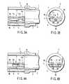
- FIG. 1Ais a longitudinal cross-sectional view showing a state in which an endoscopic hood of a first embodiment of the present invention is attached;
- FIG. 1Bis a front view showing the endoscopic hood of the first embodiment
- FIG. 2Ais a longitudinal cross-sectional view showing a major section in a state in which a clipping device is inserted into the endoscopic hood of the first embodiment
- FIG. 2Bis a front view of an endoscopic hood in a state in which the clipping device inserted into the endoscopic hood has its rotation restricted;
- FIG. 2Cis a longitudinal cross-sectional view showing a major section in a state in which the stopping of bleeding is performed with the use of the clipping device projected from the endoscopic hood of the first embodiment;
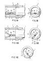
- FIG. 3Ais a longitudinal cross-sectional view showing a major section in a state in which a high frequency snare is inserted into the endoscopic hood of the first embodiment
- FIG. 3Bis a front view showing an endoscopic hood in a state in which the high frequency snare inserted into the endoscopic hood has its rotation restricted;
- FIG. 4Ais a longitudinal cross-sectional view showing a major section in a state in which a grasping forceps is inserted into the endoscopic hood of the first embodiment
- FIG. 4Bis a front view of the endoscopic hood in a state in which the grasping forceps inserted into the endoscopic hood of the first embodiment has its rotation restricted;
- FIG. 5Ais a longitudinal cross-sectional view showing a major section in a state in which a clipping device is inserted into an endoscopic hood as a first variant of the endoscopic hood of the first embodiment;
- FIG. 5Bis a front view of the endoscopic hood in a state in which the clipping device inserted into the endoscopic hood of the first variant has its rotation restricted;
- FIG. 6Ais a longitudinal cross-sectional view showing a major section in a state in which a clipping device is inserted into an endoscopic hood as a second variant of the endoscopic hood of the first embodiment;
- FIG. 6Bis a front view showing a state in which the clipping device inserted into the endoscopic hood of the second variant has its rotation restricted;
- FIG. 7Ais a longitudinal cross-sectional view showing a major section in a state in which a clipping device is inserted into an endoscopic hood according to a second embodiment of the present invention
- FIG. 7Bis a front view of the endoscopic hood in a state in which the clipping device inserted into the endoscopic hood of the second embodiment has its rotation restricted.
- FIG. 8Ais a longitudinal cross-sectional view showing a major section in a state in which a clipping device is inserted into an endoscopic hood according to a third embodiment of the present invention.
- FIG. 8Bis a front view of the endoscopic hood in a state in which the clipping device inserted into the endoscopic hood of the third embodiment has its rotation restricted;
- FIG. 8Cis a front view of the endoscopic hood in a state in which the distal end of a treating tool in the third embodiment is rotated onto a circular arc section;
- FIG. 9Ais a longitudinal cross-sectional view showing a major section in a state in which a clipping device is inserted into an endoscopic hood according to a fourth embodiment of the present invention.
- FIG. 9Bis a front view showing a state in which the clipping device inserted into the endoscopic hood of the fourth embodiment has its rotation restricted;
- FIG. 10Ais a longitudinal cross-sectional view showing a major section in a state in which a clipping device is inserted into an endoscopic hood according to a fifth embodiment of the present invention.
- FIG. 10Bis a front view showing a state in which the clipping device inserted into the endoscopic hood of the fifth embodiment is restricted from being rotated in a clockwise direction;
- FIG. 10Cis a front view showing a state in which the clipping device inserted into the endoscopic hood of the firth embodiment is restricted from being rotated in a counter-clockwise direction;
- FIG. 11Ais a longitudinal cross-sectional view showing a major section in a state in which a clipping device is inserted into an endoscopic hood according to a sixth embodiment of the present invention.
- FIG. 11Bis a front view of the endoscopic hood in a state in which the clipping device inserted into the endoscopic hood of the sixth embodiment has its rotation restricted;
- FIG. 12Ais a longitudinal cross-sectional view showing a major section in a state in which a clipping device is inserted into an endoscopic hood according to a seventh embodiment of the present invention.
- FIG. 12Bis a front view of the endoscopic hood in a state in which the clipping device inserted into the endoscopic hood of the seventh embodiment has its rotation restricted.
- FIG. 1Ashows a state in which an endoscopic hood 3 according to the present invention is mounted on a distal end portion of an insertion section 2 of an endoscope 1 .
- the endoscopic hood 3includes a substantially cylindrical cap 4 and a substantially cylindrical fixing body 5 .
- the fixing cylindrical body 5is comprised of a member for fixing the cap 4 to the distal end portion of the insertion section 2 of the endoscope 1 .
- the cap 4is formed of a rigid, transparent synthetic resin, such as an acryl resin, and preferably a transparent and hard plastic, such as polycarbonate. This structure does not prevent a visual field of the endoscope 1 .
- the cap 4has a hardness to an extent not being easily deformed.
- the hood 3has a hardness to an extent which can firmly fix the rotation of a later-described treating tool, by its cap 4 , at a time of pushing the hood 3 against a mucosa or sucking the mucosa and can retain it, at a sucking time, in such a state as to allow an adequate amount of mucosa to enter into the cap 4 .
- a substantially ring-like engaging recess 4 a of a smaller outer diameteris formed on an outer peripheral surface of a proximal end portion of the cap 4 .
- the cylindrical fixing body 5is made of a soft plastic material, such as vinyl chloride, polyurethane and fluorine resin, rubbers such as latex, silicone, isoprene and neoprene, or synthetic resin material.
- the distal end portion of the cylindrical fixing body 5is press-fitted over the cap 4 in such a state as to be externally inserted over the engaging recess 4 a of the cap 4 .
- the joining portions of the outer section of the cylindrical fixing body 5 and the engaging recess 4 aare connected together by an adhesive.
- the fixing of the cap 4 and cylindrical fixing body 5may be made by means of a screw, etc., or may be more firmly made with the use of an ultrasonic wave, solvent, etc.
- the hood 3is detachably mounted to the distal end portion of the insertion section 2 of the endoscope 1 .
- the cylindrical fixing body 5can be detachably mounted over the cap 4 so as to correspond to the distal end portion of the insertion section 2 of endoscopes of various diameters. That is, it is possible to commonly use one endoscopic hood 3 for endoscopes 1 of various diameters.
- a rotation restricting section 7 for the treating tool 6is provided at an inner surface of the cap 4 .
- the rotation restricting section 7has a pair of upper rails 8 a , 8 a , left and right, and a pair of lower rails 8 b , 8 b , left and right.
- the respective upper rails 8 a , 8 a and lower rails 8 b , 8 bare projected from the inner surface of the cap 4 .
- a channel 9 for allowing the insertion of the treating toolis provided at a distal end face 2 a of the insertion section 2 of the endoscope 1 .
- the upper rails 8 a , 8 a and lower rails 8 b , 8 bare arranged each at both sides relative to a solid line Y 1 passing through the axis of the insertion section 2 and the center of the channel 9 and extend in a parallel array along a dotted line x of a direction orthogonal to the solid line Y 1 .
- the cross-sectional configuration of the cap 4is set to such a relation that the pair of rails 8 a , 8 a and pair of rails 8 b , 8 b are arranged in a parallel array relative to the dotted line x drawn vertical to the solid line Y 1 passing through the center of the channel 9 and that the distance d between the upper rail 8 a and the lower rail 8 b is bisected by the dotted line x.
- these rails 8 a and 8 bare set to dimensions such that, when the mucosa, etc., is to be sucked into the cap 4 , the rails provide no bar to that suction.
- these rails 8 a and 8 bare such as to have, for example, a length L of about 2 mm to 13 mm, a thickness ta of about 0.5 mm to 3 mm, the distance d between the rail 8 a and the rail 8 b being about 2 mm to 5 mm, a width wa of the upper rail 8 a being about 1 mm to 6 mm and a width wb of the lower rail 8 b being about 1 mm to 6 mm.
- cap 4 and the rails 8 a and 8 bmay be formed as separate members and be fixedly bonded together. However, it is desirable that, in view of the advantage of being lower in cost, eliminating the need to be adhesively bonded, and so on, the cap 4 and these rails 8 a , 8 b be formed as an integral unit with the use of the same material.
- the endoscopic hood 3is attached to the distal end portion of the insertion section 2 of the endoscope 1 , it is so done in a positional relation as shown in FIG. 1 B. That is, the positional relation is such that the solid line Y 1 drawn in a state to pass through the center of the distal end of the insertion section 2 of the endoscope 1 and the center of the channel 9 is aligned with a dotted line Y 2 drawn in a state to have the cross-sectional configuration of the cap 4 set in a mirror image (line symmetry) relation.
- the treating tool 6is inserted into the body of a patient via the channel 9 for allowing the insertion of the treating tool of the endoscope 1 .
- the treating tool 6 projected from the distal end of the insertion section 2 of the endoscope 1is inserted in an area between the upper and lower rails 8 a and 8 b of the cap 4 .
- the distal end of the treating tool 6is abutted against the upper rail 8 a or lower rail 8 b of the inner surface of the cap 4 whereby the treating tool 6 is restricted from being rotated about an axial direction of the insertion section 2 of the endoscope 1 .
- the hood 3is attached to the distal end portion of the insertion section of the endoscope 1 .
- a corresponding treating tool 6is so set that it is used in combination with the endoscope 1 .
- a clipping device 10as shown in FIGS. 2A to 2 C is used as the treating tool 6 .
- the clipping device 10includes a narrow elongated flexible coil sheath 10 a inserted through the channel 9 of the endoscope 1 .
- a holding-down tube 10 bis arranged at a distal end of the coil sheath 10 a .
- a proximal end side of a clip 10 cis inserted, the clip 10 c having a pair of arms.
- the clip 10 cbeing drawn into the holding-down tube 10 b , clips a living tissue in a body cavity of the patient.
- the distal end of the coil sheath 10 ais projected from the distal end of the insertion section 2 of the endoscope 1 .
- the clip 10 c on the distal end of the coil sheath 10 a projected from the distal end of the insertion section 2is set in a sandwiched state at an area between the upper rail 8 a and the lower rail 8 b of the inner surface of the cap 4 as shown in FIG. 2 B.
- the clip 10 c of the clipping device 10is abutted against the upper rail 8 a or the lower rail 8 b of the inner surface of the cap 4 to restrict the clip 10 c from being rotated about the axial direction of the insertion section 2 of the endoscope 1 .
- an operationis done for inserting the endoscope 1 into the body cavity of the patient.
- an operation, not shown, of the endoscope 1is performed to allow the distal end's opening of the cap 4 of the hood 3 to be moved onto a region of interest where the bleeding of a living tissue H is desired to be stopped.
- the clip 10 cbeing held in the cap 4 , is projected via the distal end's opening of the cap 4 and, while being contacted with the living tissue H, abutted against the living tissue H.
- the clip 10 cis abutted against the living tissue H.
- This high frequency snare 11includes an elongated snare sheath 11 a formed of a flexible tube inserted through the channel 9 of the endoscope 1 , a snare wire 11 b insertable back and forth in the snare sheath 11 a and a loop-like section 11 c on the distal end of the snare wire 11 b.
- the high frequency snare 11is set in the endoscope 1 before inserting the endoscope 1 into the body cavity of the patient. At this time, the high frequency snare 11 is inserted through the channel 9 of the endoscope 1 and the distal end portion of the snare sheath 11 a is projected from the distal end of the insertion section 2 of the endoscope 1 .
- the loop-like section 11 c on the distal end of the snare sheath 11 a projected from the distal end of the insertion section 2is set in a sandwiched state at an area between the upper rail 8 a and the lower rail 8 b of the inner surface of the cap 4 as shown in FIG. 3 B.
- the loop-like section 11 c of the high frequency snare 11is abutted against the upper rail 8 a or the lower rail 8 b of the inner surface of the cap 4 to restrict the loop-like section 11 c from being rotated about the axial direction of the insertion section 2 of the endoscope 1 .
- an operationis performed for inserting the endoscope 1 into the body cavity of the patient.
- the operation section, not shown, of the endoscope 1is operated to allow the distal end's opening of the cap 4 of the hood 3 to be moved onto a to be resected region of the living tissue.
- the loop-like section 11 c held in the cap 4is projected via the distal end's opening of the cap 4 and operated in such a state as to be applied to the living tissue.
- an operationis performed in a manner to apply the loop-like section 11 c to the living tissue.
- an operation section not shown of the high frequency snare 11is operated to allow the loop-like section 11 c to be drawn back and the living tissue to be resected.
- This grasping forceps 12includes an elongated sheath 12 a inserted through the channel 9 of the endoscope 1 , a pair of forceps members 12 b provided to be openable and closable at the distal end of the sheath 12 a , a pair of link members 12 c connected to the proximal end of the forceps members 12 b and an operation wire, not shown, insertable back and forth in the sheath 12 a .
- the distal end of the operation wireis coupled to the proximal end of the link members 12 c.
- the grasping forceps 12is set in the endoscope 12 before inserting the endoscope 1 into the body cavity of the patient. At this time, the grasping forceps 12 is inserted into the channel 9 of the endoscope 1 and the distal end of the sheath 12 a is projected from the distal end of the insertion section 2 of the endoscope 1 .
- the forceps member 12 b at the distal end of the sheath 12 a projected from the distal end of the insertion section 2is set in a sandwiched state between the upper rail 8 a and the lower rail 8 b of the inner surface of the cap 4 as shown in FIG. 4 B.
- the forceps member 12 b of the grasping forceps 12is abutted against the upper rail 8 a or the lower rail 8 b of the inner surface of the cap 4 to restrict the forceps member 12 b from being rotated about the axial direction of the insertion section 2 of the endoscope 1 .
- an operationis performed for inserting the endoscope 1 into the body cavity of the patient.
- an operation section, not shown, of the endoscope 1is operated to allow the distal end's opening of the cap 4 of the hood 3 to be moved onto a to be grasped region of the living tissue.
- the forceps members 12 b of the grasping forceps 12are projected to allow these members to be abutted against the living tissue or the living tissue is drawn back into the cap 4 by the sucking operation of the endoscope 1 to set these members 12 b in abutting relation to the living tissue.
- the operation section, not shown, of the grasping forces 12is operated to grasp the living tissue.
- the rotation restricting section 7is provided on the inner surface of the cap 3 attached to the forward end of the insertion section 2 of the endoscope 1 .
- the treating tool 6 projected from the distal end of the insertion section 2 of the endoscope 1is set in abutting engagement with the upper and lower rails 8 a and 8 b of the rotation restricting section 7 . This restricts the treating tool 6 from being rotated about the axial direction of the insertion section 2 of the endoscope 1 .
- the clipping device 10high frequency snare 11 , grasping forceps 12 , etc., are explained as being used as the treating tool 6
- the present embodimentmay be so structured as to fix the rotation of biopsy forceps for living tissue collection as in the case of the grasping forceps 12 .
- the endoscopic hood 3may be replaced by a first variant of an endoscopic hood 3 as shown in FIGS. 5A and 5B.
- the variant of the first embodimentonly one pair of lower rails 8 b , right and left, are provided on the inner surface of a cap 4 and, similarly, these lower rails 8 b restrict the rotation of the distal end of the treating tool 6 .
- the cross-sectional configuration of the cap 4is so set as to define a distance of d/2 between a dotted line x drawn from the center of a channel 9 and the lower rails 8 b as shown in FIG. 5 B.
- the number of rails projected on the inner surface of the cap 4can be reduced in comparison with that of the first embodiment and it is possible to suck more mucosa into the cap 4 .
- only a pair of upper rails 8 amay be provided on the inner surface of a cap 4 .
- the rotation of the distal end of the treating tool 6can be restricted by these upper rails 8 a.
- FIGS. 7A and 7Bshow a second embodiment of the present invention.
- the endoscopic hood 3 according to the first embodimentis so varied as to provide a cap 4 of a different structure as will be set out below.
- the cap 4 of an endoscopic hoodhas its inner wall surface portion raised toward a center direction to provide a planar section 21 .
- the planar section 21is situated in a horizontal position corresponding to a lower portion of a channel 9 of the endoscope 1 as shown in FIG. 7 B. It is to be noted that the attaching of the hood 3 to the endoscope 1 is the same as that in the first embodiment and, here, an explanation of it will be omitted.
- the hoodis attached to the distal end of the insertion section 2 of the endoscope 1 .
- a treating tool 6such as a clipping device 10 , is set for use in combination with the endoscope 1 before the insertion of the endoscope 1 into the body cavity of the patient.
- a clip 10 c on the distal end of the coil sheath 10 a which is projected from the distal end of the insertion section 2is set in an abutted state along the planar section 21 of the inner surface of the cap 4 as shown in FIG. 7 B.
- the clip 10 c of the clipping device 10is abutted against the planar section 21 of the inner surface of the cap 4 to restrict the clip 10 c from being rotated about the axial direction of the insertion section 2 of the endoscope 1 .
- a subsequent operationis the same as that of the first embodiment and, here, an explanation of it is omitted.
- the portion of the inner wall surface of the cap 4is raised to provide the planar section 21 .
- the clip 10 c of the clipping device 10is restricted from being rotated about the axial direction of the insertion section 2 of the endoscope 1 .
- the cap 4has a simpler inner configuration and has an advantage of being formed in a simpler way.
- FIGS. 8A to 8 Cshow a third embodiment of the present invention.
- the cap 4 of the hood 3 according to the first embodimentis so varied as to provide a cap 4 of a different structure as will be set out below.
- a planar section 21 similar to the planar section 21 of the second embodimentis provided on the inner surface of the cap 4 and, in addition, a circular arc-like recess 22 is provided at a middle area of the planar section 21 .
- attaching an endoscopic hood 3 to the endoscope 1is the same as that in the first embodiment and, here, an explanation of it is omitted.
- the hood 3is attached to the distal end of the insertion section 2 of the endoscope 1 .
- the endoscope 1is inserted into the body cavity of the patient.
- a treating tool 6such as a clipping device 10 is set so that it is used in combination with the endoscope 1 .
- This clipping device 10is inserted via an opening on a proximal end side of the endoscope into a channel 9 provided at the endoscope 1 .
- the clipping device 10is set such that the distal end portion of its coil sheath 10 a is projected from the distal end of the insertion section 2 of the endoscope 1 .
- a clip 10 c on the distal end of the coil sheath 10 a projected from the distal end of the insertion section 2is set to a state abutted along the planar section 21 of the inner surface of the cap 4 as shown in FIG. 8 B.
- the clip 10 c of the clipping device 10is abutted against the planar section 21 of the inner surface of the cap 4 to restrict the clip 10 c from being rotated about an axial direction of the insertion section 2 of the endoscope 1 .
- the distal end of the clipping device 10is once projected from the cap 4 and then the clip 10 c is rotated about the axial direction to retract it into the cap 4 .
- the clip 10 c of the clipping deviceis allowed to be readily moved into the above-mentioned recess 22 .
- a subsequent operationis the same as that of the above-mentioned first embodiment and an explanation of it is omitted.
- the point of time at which the clipping device 10 as the treating tool 6 is inserted into the channel 9 of the endoscope 1can be set after the insertion of the endoscope 1 into the body cavity of the patient. Further, even if the clip 10 c is projected from the insertion section 2 in such a state as not to be abutted against the planar section 21 , it is possible to abut the clip 10 c against the planar surface 21 by rotating the clip 10 c within the cap 4 .
- FIGS. 9A and 9Bshow a fourth embodiment of the present invention.
- the hood 3 according to the first embodimentis so varied as to provide a cap 4 of a different structure as will be set out below.
- a pair of recess-like engaging grooves 31are so provided in the inner surface of the cap 4 of the first embodiment as to extend along the axial direction.
- the size of the respective grooves 31is so set as to allow the treating tool 6 , for example, the clip 10 c of the clipping device 10 , which is used in combination with the endoscope 1 to engage these grooves.
- the depth tb of the engaging groove 31is, for example, about 0.2 mm to 1 mm.
- the hood 3is attached to the distal end of the insertion section 2 of the endoscope 1 .
- the treating tool 6for example, a clipping device 10 is so set, before inserting the endoscope 1 into the body cavity of the patient, as to be used in combination with the endoscope 1 .
- the distal end of its coil sheath 10 ais projected from the distal end of the insertion section 2 of the endoscope 1 .
- a clip 10 c on the distal end of the coil sheath 10 a which is projected from the distal end of the insertion section 2is so set as to be inserted in the engaging grooves 31 of the cap 4 as shown in FIG. 9 B.
- the clip 10 c of the clipping device 10is fitted into engagement with the engaging grooves in the inner surface of the cap 4 .
- the clip 10 cis restricted from being rotated about the axial direction of the insertion section 2 of the endoscope 1 .
- a subsequent operationis the same as that of the first embodiment and further explanation of it is omitted.
- a pair of recess-like engaging grooves 31 , right and left, in the inner surface of the cap 4extend along the axial direction.
- the clip 10 c projected from the distal end of the insertion section 2can be so set as to be fitted in the engaging grooves 31 of the cap 4 as shown in FIG. 9 B. By doing so it is possible to restrict the clip 10 c from being rotated about the axial direction of the insertion section 2 of the endoscope 1 .
- two engaging grooves 31are provided in the inner surface of the cap 4 and it is, therefore, possible to secure more capacity with which a living tissue, such as the mucosa, is sucked into the cap 4 and hence to obtain the advantage of sucking much more mucosa into the cap 4 .
- FIGS. 10A to 10 Cshow a fifth embodiment of the present invention.
- the endoscopic hood 3 of the first embodiment(see FIGS. 1A through 4B) is so varied as to provide a cap of different structure as will be set out below.
- a slit 41is formed in the inner surface of a cap 4 as a through hole extending through the inner and outer wall surface sides.
- the slit 41extends along an axial direction from the distal end of the insertion section 2 of the endoscope 1 to a position of a distal end of the cap 4 . As shown in FIG.
- the width wc of the slit 41is, for example, about 2 mm to 12 mm and a treating tool 6 , for example, a clip 10 c of the clipping device 10 , is used in combination with the endoscope 1 and set in an engaging relation to the slit 41 .
- a treating tool 6for example, a clip 10 c of the clipping device 10
- the clip 10 cis restricted from being rotated about the axial direction of the insertion section 2 of the endoscope 1 . Attaching the hood 3 to the endoscope 1 is accomplished in the same way as that of the first embodiment and the further explanation of it is, therefore, omitted.
- the hood 3is attached to the distal end of the insertion section 2 of the endoscope 1 .
- a treating tool 6for example, the clipping device 10 , used in combination with the endoscope 1 is set before inserting the endoscope 1 into the body cavity of the patient 1 .
- the distal end of its coil sheath 10 ais projected from the distal end of the insertion section 2 of the endoscope 1 .
- the clip 10 c projected from the insertion section 2is so set that the clip 10 c is inserted into the slit 41 in the inner wall side of the cap 4 as shown in FIG. 10 B.
- the clip 10 cengages the slit 41 in the inner wall side of the cap 4 , so that, within the width wc range of the slit 41 , the clip 10 c is restricted from being rotated about the axial direction of the insertion section 2 of the endoscope 1 .
- an operationis made for inserting the insertion section 2 of the endoscope 1 into the body cavity of the patient.
- the rotation of the distal end of the clip 10 c within the cap 4can be restricted within the width wc range of the slit 41 , for example, within a range of about below 900.
- a slitmay be provided in the inner wall surface of the cap 4 to allow one end of the distal end portion of the treating tool 6 to barely enter therein and the distal end of the treating tool 6 be so fixed as to allow a rotation in a given position.
- the treating tool 6may be inserted from a proximal end side to restrict the rotation of the distal end portion of the treating tool 6 within the hood 3 .
- the operation section, not shown, of the endoscope 1is operated to move the distal end's opening of the cap 4 of the hood 3 to a to be clipped region of a living tissue.
- the clip 10 c held within the cap 4is projected via the distal end's opening of the hood 3 .
- the clip 10 cis so set as to be abutted against the living tissue and, in this state, the operation section of the clipping device 10 is operated to allow the living tissue to be clipped by its clip 10 c.
- the slit 41is formed in the inner wall surface of the cap 4 as a through hole extending through the inner and outer wall surface sides and the clip 10 c on the distal end of the coil sheath 10 a is set in an engaged relation to the slit 41 .
- the rotation of the distal end portion of the clip 10 ccan be restricted to an extent of, for example, about below 900 within the cap 4 . Therefore, the clip 10 c is readily oriented toward a desired direction, thus offering the advantage of performing a treatment quickly.
- FIGS. 11A and 11Bshow a sixth embodiment of the present invention.
- the hood 3 according to the first embodimentis so varied as to provide a cap 4 of a different structure as will be set out below.
- a pair of slits 51is formed in the inner wall surface of the cap 4 as through holes extending through its inner and outer wall surface sides.
- these slits 51extend along an axial direction from the distal end of the insertion section 2 of the endoscope 1 to a position of the distal end of the cap 4 .
- attaching the hood 3 to the endoscope 1is accomplished in the same way as that of the first embodiment and, here, further explanation of it is, therefore, omitted.
- the endoscopic hood 3is attached to the distal end portion of the insertion section 2 of the endoscope 1 .
- a treating toolfor example, a clipping device 10 , is set before inserting the endoscope 1 into the body cavity of the patient so that the device is used in combination with the endoscope 1 .
- a clip 10 c on the distal end of the coil sheath 10 a which is projected from the distal end of the insertion section 2is set such that, as shown in FIG. 11B, the clip 10 c is fitted in the right and left slits 51 in the inner wall surface of the cap 4 .
- the clip 10 c of the clipping device 10is set in an engaged relation to the slits 51 in the inner wall surface of the cap 4 to restrict the clip 10 c from being rotated about the axial direction of the insertion section 2 of the endoscope 1 .
- an operationis made for inserting the insertion section 2 of the endoscope 1 into the body cavity of the patient.
- an operation section, not shown, of the endoscope 1is operated to move the distal end's opening of the cap 4 of the endoscopic hood to a to be clipped region of the living tissue.
- the clip 10 c held within the cap 4is projected via the distal end's opening of the cap 4 .
- the clip 10 cis set in abutting contact with the living tissue and, by operating the operation section of the clipping device 10 , clips the living tissue.
- the pair of slits 51are formed in the inner wall of the cap 4 as through holes extending through the inner and outer wall surface sides and the clip 10 c on the distal end of the coil sheath 10 a is fitted in the right and left slits 51 in the inner wall of the cap 4 to set the clip 10 c in engaging contact with the slits in the inner wall of the cap 4 to restrict the clip 10 c from being rotated about the axial direction of the insertion section 2 of the endoscope 1 .
- this embodimenttherefore, there is no restriction against the opening width of the clip 10 c within the cap 4 , thus offering the advantage of clipping more living tissue.
- FIGS. 12A and 12Bshow a seventh embodiment of the present invention.
- the first embodiment(see FIGS. 1A through 4B) is so varied as to provide an endoscopic hood 3 having a different structure as will be set out below.
- the cap 4 , fixing cylindrical body 5 and two pairs of rails 8 a , 8 b in the first embodimentare made of the same material to provide an integral unit 61 .
- the material of the integral unit 61is made of a living tissue substance mainly consisting of a block copolymer comprising both a copolymer block mainly consisting of a vinyl aromatic compound and a block mainly consisting of a conjugate diene compound. The remaining portion of this embodiment is the same as that of the first embodiment.
- an endoscopic hood 3is attached to the distal end of the insertion section 2 of the endoscope 1 .
- a clipping device 10 as a treating tool 6is set, before inserting the endoscope 1 into the body cavity of the patient, so that the device is used in combination with the endoscope 1 .
- the clipping device 10is inserted via the channel 9 of the endoscope 1 and the distal end of a coil sheath 10 a is projected from the distal end of the insertion section 2 of the endoscope 1 .
- a clip 10 c on the distal end of the coil sheath 10 a which is projected from the distal end of the insertion section 2is set in a sandwiched relation between the upper rails 8 a or the lower rails 8 b of the inner surface of the cap 4 , so that the clip 10 c is restricted from being rotated about the axial direction of the insertion section 2 of the endoscope 1 .
- an operationis performed for inserting the endoscope 1 into the body cavity of the patient.
- an operation section, not shown, of the endoscope 1is performed to move the distal end's opening of the cap 4 of the hood 3 to a bleeding region of a living tissue H so that the bleeding may be stopped.
- the clip 10 c held within the cap 4is projected via the distal end's opening of the cap 4 and set in abutting contact with the living tissue.
- the operation section of the clipping device 10is operated to clip the living tissue by means of the clip 10 c.
- the hood 3is formed of an integral unit 61 made up of a soft member. For this reason, such integral unit 61 is attached to the distal end of the insertion section 2 of the endoscope 1 and there is an advantage of readily inserting it into the body cavity of the patient.
Landscapes
- Health & Medical Sciences (AREA)
- Life Sciences & Earth Sciences (AREA)
- Surgery (AREA)
- Biomedical Technology (AREA)
- Medical Informatics (AREA)
- Optics & Photonics (AREA)
- Pathology (AREA)
- Radiology & Medical Imaging (AREA)
- Biophysics (AREA)
- Engineering & Computer Science (AREA)
- Physics & Mathematics (AREA)
- Heart & Thoracic Surgery (AREA)
- Nuclear Medicine, Radiotherapy & Molecular Imaging (AREA)
- Molecular Biology (AREA)
- Animal Behavior & Ethology (AREA)
- General Health & Medical Sciences (AREA)
- Public Health (AREA)
- Veterinary Medicine (AREA)
- Endoscopes (AREA)
- Surgical Instruments (AREA)
- Instruments For Viewing The Inside Of Hollow Bodies (AREA)
Abstract
Description
The present invention relates to an endoscopic hood which is attached to a distal end of an insertion section of an endoscope and, when the endoscope is inserted into a body cavity of a patient, protects the forward end portion of an insertion section of the endoscope.
Generally, upon an examination and surgery under an endoscope, a treating tool is used which is inserted into a body cavity of a patient via a tool insertion channel of the endoscope. As the treating tool for an endoscope there is a treating tool of such a type as to grasp a living tissue, such as a clipping device, a high frequency snare, grasping forceps as well as a biopsy forceps.
When the grasping or clipping procedure is performed with the use of this type of treating tool, the endoscope itself or the treating tool itself is moved or rotated, so that the distal end of the treating tool is so operated as to be directed toward a desired direction. And such procedure is performed to fix the tool to a given position with the distal end of the treating tool oriented toward a desired direction. For this reason, for the treating tool for grasping or clipping a living tissue it is important to set a direction in which the living tissue is grasped or clipped.
For example, Jpn. Pat. Appln. KOKAI Publication Nos. 8-131397 and 9-66019 disclose a structure in which, upon examination and surgery under an endoscope, an endoscopic hood of a substantially cylindrical configuration is detachably mounted to the distal end of the insertion section of the endoscope. In this case, the treating tool inserted into an inside of a body of a patient via a tool insertion channel of an endoscope is projected toward a front direction from the distal end of an endoscopic hood.
Further, the inner surface of the endoscopic hood of a conventional structure is formed to have a substantially smooth wall surface. For this reason, the treating tool slips upon being contacted with the inner wall surface of the endoscopic hood and is retained in a state to be freely rotatable about an axial direction of the insertion section of the endoscope. Even if, therefore, the distal end of the treating tool is correctly oriented toward a desired direction, the endoscope itself may be rotated, or the treating tool may be rotated about an axial direction of the insertion section of the endoscope, due to an action of an operation force upon the treating tool when the living tissue is grasped or clipped by the treating tool. In this situation, the distal end of the treating tool cannot be correctly retained toward an intended direction. For this reason, it takes a lot of time to fixedly orient the distal end of the treating tool toward the desired direction and it also takes a lot of a skill to perform such an operation.
It is accordingly an object of the present invention to provide an endoscopic hood which can restrict the distal end of a treating tool from being rotated about its axial direction and orient the tool toward a desired direction and do this treating procedure quickly and accurately.
In order to achieve the above-mentioned object of the present invention, the invention ofclaim 1 provides an endoscopic hood having a substantially cylindrical cap attached to a distal end of an insertion section of an endoscope to protect the distal end of an insertion section of the endoscope, the cap having a rotation restricting section in its inner surface which, when a treating tool is projected from the distal end of the insertion section of the endoscope, abuts against the treating tool to restrict the treating tool from being rotated about an axial direction of the insertion section of the endoscope.
According to the invention ofclaim 1, the treating tool projected from the distal end of the insertion section of the endoscope is set in abutting engagement with the rotation restricting section of the inner surface of the cap attached to the distal end of the endoscope. By doing so, the treating tool is restricted from being rotated about the axial direction of the insertion section of the endoscope. Further, after inserting the endoscope into a body cavity of a patient, the distal end of the treating tool held within the cap is projected onto a living tissue or, with the living tissue drawn into the cap, the distal end of the treating tool is abutted against the living tissue and the tool grasps or clips the living tissue.
According to the present invention, therefore, the distal end of the treating tool is initially restricted from being rotated about the axial direction and can be correctly oriented toward a desired direction, so that it is possible to perform a correct treatment quickly.
The invention ofclaim 2 is such that, in the endoscopic hood ofclaim 1, the rotation restricting section is comprised of a projection projected toward an inner direction on the inner surface of the cap.
According to the invention ofclaim 2, the treating tool projected from the distal end of the insertion section of the endoscope is set in abutting engagement with the projection of the rotation restricting section of the inner surface of the cap attached to the distal end of the insertion section of the endoscope. By doing so, the treating tool is restricted from being rotated about the axial direction of the insertion section of the endoscope.
The invention ofclaim 3 is such that, in the endoscopic hood ofclaim 2, the projection is comprised of a planar surface with a portion of the inner wall surface of the cap raised toward a center direction.
According to the invention ofclaim 3, the treating tool projected from the distal end of the insertion section of the endoscope is set in abutting engagement with the projection of the rotation restricting section which is raised toward the center direction at a portion of the inner wall surface of the cap attached to the distal end of the insertion section of the endoscope. By doing so, the treating tool is restricted from being rotated about the axial direction of the insertion section of the endoscope.
The invention ofclaim 4 is such that, in the endoscopic hood ofclaim 1, the rotation restricting section is comprised of a wall groove section provided by cutting the wall of the cap from an inner wall surface side to an outer wall surface side.
The invention ofclaim 4 is such that the treating tool projected from the distal end of the insertion section of the endoscope is set into abutting engagement with the wall groove section of the rotation restricting section provided by cutting the wall of the cap from an inner wall surface side to an outer wall surface side, the cap being attached to the distal end portion of the insertion section of the endoscope. By doing so, the treating tool is restricted from being rotated about the axial direction of the insertion section of the endoscope.
The invention ofclaim 5 is such that, in the endoscopic hood ofclaim 1, the cap is made of a hard material and has a fixing cylindrical body for fixing the distal end portion of the insertion section of the endoscope to an outer peripheral surface of a proximal end side thereof.
According to the invention ofclaim 5, the fixing cylindrical body at the outer peripheral surface of the proximal end side of the cap made of the hard material is fixed to the distal end portion of the insertion section of the endoscope. By doing so, the hard cap is attached to the distal end portion of the insertion section of the endoscope.
The invention ofclaim 6 is directed to a method of using an endoscopic hood which has a substantially cylindrical cap fixed to an endoscope, the cap being attached to a distal end portion of the insertion section of the endoscope to protect the distal end portion of the insertion section of the endoscope. In the method, the cap has a rotation restricting section at an inner wall surface thereof which is set in abutting contact with a treating tool when the treating tool is projected from the distal end of the insertion section of the endoscope, and restricts the treating tool from being rotated about an axial direction of the insertion section of the endoscope. The cap is so attached to align a line, which is drawn from a center of the distal end of the endoscope to a center of a channel, with a line which is drawn in a manner to set a cross-sectional configuration of the cap in a mirror image relation.
The invention ofclaim 7 is such that, in the method for using an endoscopic hood ofclaim 6, when the cap is used, the distal end of the treating tool is opened in a mutually opposite directions to restrict a rotation of the distal end of the treating tool.
FIG. 1A is a longitudinal cross-sectional view showing a state in which an endoscopic hood of a first embodiment of the present invention is attached;
FIG. 1B is a front view showing the endoscopic hood of the first embodiment;
FIG. 2A is a longitudinal cross-sectional view showing a major section in a state in which a clipping device is inserted into the endoscopic hood of the first embodiment;
FIG. 2B is a front view of an endoscopic hood in a state in which the clipping device inserted into the endoscopic hood has its rotation restricted;
FIG. 2C is a longitudinal cross-sectional view showing a major section in a state in which the stopping of bleeding is performed with the use of the clipping device projected from the endoscopic hood of the first embodiment;
FIG. 3A is a longitudinal cross-sectional view showing a major section in a state in which a high frequency snare is inserted into the endoscopic hood of the first embodiment;
FIG. 3B is a front view showing an endoscopic hood in a state in which the high frequency snare inserted into the endoscopic hood has its rotation restricted;
FIG. 4A is a longitudinal cross-sectional view showing a major section in a state in which a grasping forceps is inserted into the endoscopic hood of the first embodiment;
FIG. 4B is a front view of the endoscopic hood in a state in which the grasping forceps inserted into the endoscopic hood of the first embodiment has its rotation restricted;
FIG. 5A is a longitudinal cross-sectional view showing a major section in a state in which a clipping device is inserted into an endoscopic hood as a first variant of the endoscopic hood of the first embodiment;
FIG. 5B is a front view of the endoscopic hood in a state in which the clipping device inserted into the endoscopic hood of the first variant has its rotation restricted;
FIG. 6A is a longitudinal cross-sectional view showing a major section in a state in which a clipping device is inserted into an endoscopic hood as a second variant of the endoscopic hood of the first embodiment;
FIG. 6B is a front view showing a state in which the clipping device inserted into the endoscopic hood of the second variant has its rotation restricted;
FIG. 7A is a longitudinal cross-sectional view showing a major section in a state in which a clipping device is inserted into an endoscopic hood according to a second embodiment of the present invention;
FIG. 7B is a front view of the endoscopic hood in a state in which the clipping device inserted into the endoscopic hood of the second embodiment has its rotation restricted.
FIG. 8A is a longitudinal cross-sectional view showing a major section in a state in which a clipping device is inserted into an endoscopic hood according to a third embodiment of the present invention;
FIG. 8B is a front view of the endoscopic hood in a state in which the clipping device inserted into the endoscopic hood of the third embodiment has its rotation restricted;
FIG. 8C is a front view of the endoscopic hood in a state in which the distal end of a treating tool in the third embodiment is rotated onto a circular arc section;
FIG. 9A is a longitudinal cross-sectional view showing a major section in a state in which a clipping device is inserted into an endoscopic hood according to a fourth embodiment of the present invention;
FIG. 9B is a front view showing a state in which the clipping device inserted into the endoscopic hood of the fourth embodiment has its rotation restricted;
FIG. 10A is a longitudinal cross-sectional view showing a major section in a state in which a clipping device is inserted into an endoscopic hood according to a fifth embodiment of the present invention;
FIG. 10B is a front view showing a state in which the clipping device inserted into the endoscopic hood of the fifth embodiment is restricted from being rotated in a clockwise direction;
FIG. 10C is a front view showing a state in which the clipping device inserted into the endoscopic hood of the firth embodiment is restricted from being rotated in a counter-clockwise direction;
FIG. 11A is a longitudinal cross-sectional view showing a major section in a state in which a clipping device is inserted into an endoscopic hood according to a sixth embodiment of the present invention;
FIG. 11B is a front view of the endoscopic hood in a state in which the clipping device inserted into the endoscopic hood of the sixth embodiment has its rotation restricted;
FIG. 12A is a longitudinal cross-sectional view showing a major section in a state in which a clipping device is inserted into an endoscopic hood according to a seventh embodiment of the present invention; and
FIG. 12B is a front view of the endoscopic hood in a state in which the clipping device inserted into the endoscopic hood of the seventh embodiment has its rotation restricted.
A first embodiment of the present invention will be described below with reference to FIGS. 1A through 4B. FIG. 1A shows a state in which anendoscopic hood 3 according to the present invention is mounted on a distal end portion of aninsertion section 2 of anendoscope 1. Theendoscopic hood 3 includes a substantiallycylindrical cap 4 and a substantiallycylindrical fixing body 5. The fixingcylindrical body 5 is comprised of a member for fixing thecap 4 to the distal end portion of theinsertion section 2 of theendoscope 1.
Further, thecap 4 is formed of a rigid, transparent synthetic resin, such as an acryl resin, and preferably a transparent and hard plastic, such as polycarbonate. This structure does not prevent a visual field of theendoscope 1. It is to be noted that thecap 4 has a hardness to an extent not being easily deformed. For example, thehood 3 has a hardness to an extent which can firmly fix the rotation of a later-described treating tool, by itscap 4, at a time of pushing thehood 3 against a mucosa or sucking the mucosa and can retain it, at a sucking time, in such a state as to allow an adequate amount of mucosa to enter into thecap 4. A substantially ring-likeengaging recess 4aof a smaller outer diameter is formed on an outer peripheral surface of a proximal end portion of thecap 4.
Further, thecylindrical fixing body 5 is made of a soft plastic material, such as vinyl chloride, polyurethane and fluorine resin, rubbers such as latex, silicone, isoprene and neoprene, or synthetic resin material. The distal end portion of thecylindrical fixing body 5 is press-fitted over thecap 4 in such a state as to be externally inserted over the engagingrecess 4aof thecap 4. The joining portions of the outer section of thecylindrical fixing body 5 and theengaging recess 4aare connected together by an adhesive. It is to be noted that the fixing of thecap 4 andcylindrical fixing body 5 may be made by means of a screw, etc., or may be more firmly made with the use of an ultrasonic wave, solvent, etc.
By the elastic deformation of thecylindrical fixing body 5, thehood 3 is detachably mounted to the distal end portion of theinsertion section 2 of theendoscope 1. In this case, without damaging the distal end portion of theinsertion section 2 of theendoscope 1 by an elastic deformation involved, thecylindrical fixing body 5 can be detachably mounted over thecap 4 so as to correspond to the distal end portion of theinsertion section 2 of endoscopes of various diameters. That is, it is possible to commonly use oneendoscopic hood 3 forendoscopes 1 of various diameters.
Arotation restricting section 7 for the treatingtool 6 is provided at an inner surface of thecap 4. As shown in FIG. 1B, therotation restricting section 7 has a pair ofupper rails lower rails upper rails lower rails cap 4.
Achannel 9 for allowing the insertion of the treating tool is provided at adistal end face 2aof theinsertion section 2 of theendoscope 1. Here, theupper rails lower rails insertion section 2 and the center of thechannel 9 and extend in a parallel array along a dotted line x of a direction orthogonal to the solid line Y1. Therefore, the cross-sectional configuration of thecap 4 is set to such a relation that the pair ofrails rails channel 9 and that the distance d between theupper rail 8aand thelower rail 8bis bisected by the dotted line x.
Further, theserails cap 4, the rails provide no bar to that suction. Preferably, theserails rail 8aand therail 8bbeing about 2 mm to 5 mm, a width wa of theupper rail 8abeing about 1 mm to 6 mm and a width wb of thelower rail 8bbeing about 1 mm to 6 mm.
It is to be noted that thecap 4 and therails cap 4 and theserails
In the case where theendoscopic hood 3 is attached to the distal end portion of theinsertion section 2 of theendoscope 1, it is so done in a positional relation as shown in FIG.1B. That is, the positional relation is such that the solid line Y1 drawn in a state to pass through the center of the distal end of theinsertion section 2 of theendoscope 1 and the center of thechannel 9 is aligned with a dotted line Y2 drawn in a state to have the cross-sectional configuration of thecap 4 set in a mirror image (line symmetry) relation.
In this state, the treatingtool 6 is inserted into the body of a patient via thechannel 9 for allowing the insertion of the treating tool of theendoscope 1. In this case, as shown in FIGS. 2A and 2B, the treatingtool 6 projected from the distal end of theinsertion section 2 of theendoscope 1 is inserted in an area between the upper andlower rails cap 4. At this time, the distal end of the treatingtool 6 is abutted against theupper rail 8aorlower rail 8bof the inner surface of thecap 4 whereby the treatingtool 6 is restricted from being rotated about an axial direction of theinsertion section 2 of theendoscope 1.
The operation of the present embodiment thus structured will be explained below. First, thehood 3 is attached to the distal end portion of the insertion section of theendoscope 1. Before theendoscope 1 is inserted into the body cavity of the patient, a corresponding treatingtool 6 is so set that it is used in combination with theendoscope 1. Here, an explanation will be made about the case where aclipping device 10 as shown in FIGS. 2A to2C is used as the treatingtool 6. Theclipping device 10 includes a narrow elongatedflexible coil sheath 10ainserted through thechannel 9 of theendoscope 1. A holding-downtube 10bis arranged at a distal end of thecoil sheath 10a. Into the holding-downtube 10ba proximal end side of aclip 10cis inserted, theclip 10chaving a pair of arms. Theclip 10c, being drawn into the holding-downtube 10b, clips a living tissue in a body cavity of the patient.
And after theclipping device 10 has been inserted through thechannel 9 of theendoscope 1, the distal end of thecoil sheath 10ais projected from the distal end of theinsertion section 2 of theendoscope 1. Here, theclip 10con the distal end of thecoil sheath 10aprojected from the distal end of theinsertion section 2 is set in a sandwiched state at an area between theupper rail 8aand thelower rail 8bof the inner surface of thecap 4 as shown in FIG.2B. By doing so, theclip 10cof theclipping device 10 is abutted against theupper rail 8aor thelower rail 8bof the inner surface of thecap 4 to restrict theclip 10cfrom being rotated about the axial direction of theinsertion section 2 of theendoscope 1.
After this, an operation is done for inserting theendoscope 1 into the body cavity of the patient. Then an operation, not shown, of theendoscope 1 is performed to allow the distal end's opening of thecap 4 of thehood 3 to be moved onto a region of interest where the bleeding of a living tissue H is desired to be stopped. And as shown in FIG. 2C, theclip 10c, being held in thecap 4, is projected via the distal end's opening of thecap 4 and, while being contacted with the living tissue H, abutted against the living tissue H. Or with the living tissue H drawn into thecap 4 by the suction operation of theendoscope 1, theclip 10cis abutted against the living tissue H. By operating the operation section, not shown, of theclipping device 10, theclip 10cclips the bleeding portion of the living tissue H, thus stopping the bleeding of the region of interest.
In the case where ahigh frequency snare 11 as shown in FIGS. 3A and 3B is used as a treatingdevice 6, the following operation is performed. Thishigh frequency snare 11 includes anelongated snare sheath 11aformed of a flexible tube inserted through thechannel 9 of theendoscope 1, asnare wire 11binsertable back and forth in thesnare sheath 11aand a loop-like section 11con the distal end of thesnare wire 11b.
Even at a time of using ahigh frequency snare 11, substantially the same operation as that of theclipping device 10 is performed. That is, after thehood 3 has been attached to the distal end portion of theinsertion section 2 of theendoscope 1, thehigh frequency snare 11 is set in theendoscope 1 before inserting theendoscope 1 into the body cavity of the patient. At this time, thehigh frequency snare 11 is inserted through thechannel 9 of theendoscope 1 and the distal end portion of thesnare sheath 11ais projected from the distal end of theinsertion section 2 of theendoscope 1. Here, the loop-like section 11con the distal end of thesnare sheath 11aprojected from the distal end of theinsertion section 2 is set in a sandwiched state at an area between theupper rail 8aand thelower rail 8bof the inner surface of thecap 4 as shown in FIG.3B. By doing so, the loop-like section 11cof thehigh frequency snare 11 is abutted against theupper rail 8aor thelower rail 8bof the inner surface of thecap 4 to restrict the loop-like section 11cfrom being rotated about the axial direction of theinsertion section 2 of theendoscope 1.
After this, an operation is performed for inserting theendoscope 1 into the body cavity of the patient. Then, the operation section, not shown, of theendoscope 1 is operated to allow the distal end's opening of thecap 4 of thehood 3 to be moved onto a to be resected region of the living tissue. And the loop-like section 11cheld in thecap 4 is projected via the distal end's opening of thecap 4 and operated in such a state as to be applied to the living tissue. Or with the living tissue sucked into thecap 4 by the sucking operation of theendoscope 1 an operation is performed in a manner to apply the loop-like section 11cto the living tissue. In this state, an operation section not shown of thehigh frequency snare 11 is operated to allow the loop-like section 11cto be drawn back and the living tissue to be resected.
In the case where graspingforceps 12 as shown in FIGS. 4A and 4B is used as a treatingtool 6, the following operation will be performed. This graspingforceps 12 includes anelongated sheath 12ainserted through thechannel 9 of theendoscope 1, a pair offorceps members 12bprovided to be openable and closable at the distal end of thesheath 12a, a pair oflink members 12cconnected to the proximal end of theforceps members 12band an operation wire, not shown, insertable back and forth in thesheath 12a. The distal end of the operation wire is coupled to the proximal end of thelink members 12c.
At a time of using the graspingforceps 12, substantially the same operation as that of theclipping device 10 is performed. That is, after thehood 3 has been attached to the distal end of theinsertion section 2 of theendoscope 1, the graspingforceps 12 is set in theendoscope 12 before inserting theendoscope 1 into the body cavity of the patient. At this time, the graspingforceps 12 is inserted into thechannel 9 of theendoscope 1 and the distal end of thesheath 12ais projected from the distal end of theinsertion section 2 of theendoscope 1. Here, theforceps member 12bat the distal end of thesheath 12aprojected from the distal end of theinsertion section 2 is set in a sandwiched state between theupper rail 8aand thelower rail 8bof the inner surface of thecap 4 as shown in FIG.4B. By doing so, theforceps member 12bof the graspingforceps 12 is abutted against theupper rail 8aor thelower rail 8bof the inner surface of thecap 4 to restrict theforceps member 12bfrom being rotated about the axial direction of theinsertion section 2 of theendoscope 1.
After this, an operation is performed for inserting theendoscope 1 into the body cavity of the patient. Then, an operation section, not shown, of theendoscope 1 is operated to allow the distal end's opening of thecap 4 of thehood 3 to be moved onto a to be grasped region of the living tissue. In a position held into thecap 4 from the distal end's opening of thecap 4, theforceps members 12bof the graspingforceps 12 are projected to allow these members to be abutted against the living tissue or the living tissue is drawn back into thecap 4 by the sucking operation of theendoscope 1 to set thesemembers 12bin abutting relation to the living tissue. In such a state, the operation section, not shown, of the graspingforces 12 is operated to grasp the living tissue.
The above-mentioned structure ensures the following advantage. That is, according to this embodiment, therotation restricting section 7 is provided on the inner surface of thecap 3 attached to the forward end of theinsertion section 2 of theendoscope 1. And the treatingtool 6 projected from the distal end of theinsertion section 2 of theendoscope 1 is set in abutting engagement with the upper andlower rails rotation restricting section 7. This restricts the treatingtool 6 from being rotated about the axial direction of theinsertion section 2 of theendoscope 1. For this reason, with the use of thehood 3 at the distal end of theinsertion section 2 of theendoscope 1, the rotation of the distal end of the treatingtool 6 is initially restricted and it is possible to orient the treatingtool 6 toward a desired direction. This offers an advantage of performing an accurate treatment quickly.
Although, in the above-mentioned embodiment, theclipping device 10,high frequency snare 11, graspingforceps 12, etc., are explained as being used as the treatingtool 6, the present embodiment may be so structured as to fix the rotation of biopsy forceps for living tissue collection as in the case of the graspingforceps 12.
Although, in theendoscopic hood 3 according to the present embodiment, two pairs of rails (upper rails 8aandlower rails 8b) are provided on the inner surface of thecap 4, these may be replaced by a first variant of anendoscopic hood 3 as shown in FIGS. 5A and 5B. In the variant of the first embodiment, only one pair oflower rails 8b, right and left, are provided on the inner surface of acap 4 and, similarly, theselower rails 8brestrict the rotation of the distal end of the treatingtool 6. Here, the cross-sectional configuration of thecap 4 is so set as to define a distance of d/2 between a dotted line x drawn from the center of achannel 9 and thelower rails 8bas shown in FIG.5B.
In thehood 3 according to this variant, the number of rails projected on the inner surface of thecap 4 can be reduced in comparison with that of the first embodiment and it is possible to suck more mucosa into thecap 4.
As shown in a second variant of FIGS. 6A and 6B, only a pair ofupper rails 8a, right and left, may be provided on the inner surface of acap 4. In this case, the rotation of the distal end of the treatingtool 6 can be restricted by theseupper rails 8a.
FIGS. 7A and 7B show a second embodiment of the present invention. In the second embodiment of the present invention, theendoscopic hood 3 according to the first embodiment (see FIGS. 1A through 4B) is so varied as to provide acap 4 of a different structure as will be set out below.
That is, thecap 4 of an endoscopic hood according to the second embodiment has its inner wall surface portion raised toward a center direction to provide aplanar section 21. When thehood 3 is attached to the distal end of theinsertion section 2 of theendoscope 1, theplanar section 21 is situated in a horizontal position corresponding to a lower portion of achannel 9 of theendoscope 1 as shown in FIG.7B. It is to be noted that the attaching of thehood 3 to theendoscope 1 is the same as that in the first embodiment and, here, an explanation of it will be omitted.
Now, an explanation will be made below about the operation of the present embodiment. First, the hood is attached to the distal end of theinsertion section 2 of theendoscope 1. After this, a treatingtool 6, such as aclipping device 10, is set for use in combination with theendoscope 1 before the insertion of theendoscope 1 into the body cavity of the patient.
After the insertion of theclipping device 10 into thechannel 9 of theendoscope 1, the distal end of acoil sheath 10ais projected from the distal end of theinsertion section 2 of theendoscope 1. Here, aclip 10con the distal end of thecoil sheath 10awhich is projected from the distal end of theinsertion section 2 is set in an abutted state along theplanar section 21 of the inner surface of thecap 4 as shown in FIG.7B. By doing so, theclip 10cof theclipping device 10 is abutted against theplanar section 21 of the inner surface of thecap 4 to restrict theclip 10cfrom being rotated about the axial direction of theinsertion section 2 of theendoscope 1. A subsequent operation is the same as that of the first embodiment and, here, an explanation of it is omitted.
In the second embodiment, the portion of the inner wall surface of thecap 4 is raised to provide theplanar section 21. And by theplanar section 21 theclip 10cof theclipping device 10 is restricted from being rotated about the axial direction of theinsertion section 2 of theendoscope 1. By doing so, thecap 4 has a simpler inner configuration and has an advantage of being formed in a simpler way.
FIGS. 8A to8C show a third embodiment of the present invention. In the third embodiment, thecap 4 of thehood 3 according to the first embodiment (see FIGS. 1A through 4B) is so varied as to provide acap 4 of a different structure as will be set out below.
That is, according to the third embodiment, aplanar section 21 similar to theplanar section 21 of the second embodiment (see FIGS. 7A and 7B) is provided on the inner surface of thecap 4 and, in addition, a circular arc-like recess 22 is provided at a middle area of theplanar section 21. Incidentally, attaching anendoscopic hood 3 to theendoscope 1 is the same as that in the first embodiment and, here, an explanation of it is omitted.
Now the operation of the third embodiment will be explained below. First, thehood 3 is attached to the distal end of theinsertion section 2 of theendoscope 1. After this, theendoscope 1 is inserted into the body cavity of the patient. Then, with theendoscope 1 inserted into the body cavity of the patient a treatingtool 6 such as aclipping device 10 is set so that it is used in combination with theendoscope 1.
Thisclipping device 10 is inserted via an opening on a proximal end side of the endoscope into achannel 9 provided at theendoscope 1. Theclipping device 10 is set such that the distal end portion of itscoil sheath 10ais projected from the distal end of theinsertion section 2 of theendoscope 1. Here, aclip 10con the distal end of thecoil sheath 10aprojected from the distal end of theinsertion section 2 is set to a state abutted along theplanar section 21 of the inner surface of thecap 4 as shown in FIG.8B. By doing so, theclip 10cof theclipping device 10 is abutted against theplanar section 21 of the inner surface of thecap 4 to restrict theclip 10cfrom being rotated about an axial direction of theinsertion section 2 of theendoscope 1.
Now, it is assumed that, when the distal end of thecoil sheath 10ais projected from the distal end of theinsertion section 2 of theendoscope 1, theclip 10centers into the circular arc-like recess 22 of the inner surface of thecap 4 as shown in FIG.8C. In this case, theclip 10cis rotated about the axial direction within thecap 4 and, by doing so, theclip 10cof theclipping device 10 is abutted against theplanar surface 21 of the inner surface of thecap 4 as shown in FIG.8B. This prevents theclip 10cfrom being rotated about the axial direction of theendoscope 1.
In the operation-restricted state, the distal end of theclipping device 10 is once projected from thecap 4 and then theclip 10cis rotated about the axial direction to retract it into thecap 4. By doing so, as shown in FIG. 8C, theclip 10cof the clipping device is allowed to be readily moved into the above-mentionedrecess 22.
A subsequent operation is the same as that of the above-mentioned first embodiment and an explanation of it is omitted.
As set out above, the point of time at which theclipping device 10 as the treatingtool 6 is inserted into thechannel 9 of theendoscope 1 can be set after the insertion of theendoscope 1 into the body cavity of the patient. Further, even if theclip 10cis projected from theinsertion section 2 in such a state as not to be abutted against theplanar section 21, it is possible to abut theclip 10cagainst theplanar surface 21 by rotating theclip 10cwithin thecap 4.
FIGS. 9A and 9B show a fourth embodiment of the present invention. In the fourth embodiment, thehood 3 according to the first embodiment (see FIGS. 1A through 4B) is so varied as to provide acap 4 of a different structure as will be set out below.
That is, in the fourth embodiment, a pair of recess-likeengaging grooves 31, right and left, are so provided in the inner surface of thecap 4 of the first embodiment as to extend along the axial direction. The size of therespective grooves 31 is so set as to allow the treatingtool 6, for example, theclip 10cof theclipping device 10, which is used in combination with theendoscope 1 to engage these grooves. Preferably, the depth tb of the engaginggroove 31 is, for example, about 0.2 mm to 1 mm. Incidentally, attaching anendoscopic hood 3 to theendoscope 1 is accomplished in the same way as in the case of the first embodiment and further explanation of it is, therefore, omitted.
An explanation will be made about the operation of the resultant structure. In this embodiment, thehood 3 is attached to the distal end of theinsertion section 2 of theendoscope 1. After this, the treatingtool 6, for example, aclipping device 10 is so set, before inserting theendoscope 1 into the body cavity of the patient, as to be used in combination with theendoscope 1.
After theclipping device 10 is inserted through thechannel 9 of theendoscope 1, the distal end of itscoil sheath 10ais projected from the distal end of theinsertion section 2 of theendoscope 1. Aclip 10con the distal end of thecoil sheath 10awhich is projected from the distal end of theinsertion section 2 is so set as to be inserted in the engaginggrooves 31 of thecap 4 as shown in FIG.9B. At this time, theclip 10cof theclipping device 10 is fitted into engagement with the engaging grooves in the inner surface of thecap 4. By doing so, theclip 10cis restricted from being rotated about the axial direction of theinsertion section 2 of theendoscope 1. A subsequent operation is the same as that of the first embodiment and further explanation of it is omitted.
In the above-mentioned structure, a pair of recess-likeengaging grooves 31, right and left, in the inner surface of thecap 4 extend along the axial direction. For this reason, theclip 10cprojected from the distal end of theinsertion section 2 can be so set as to be fitted in the engaginggrooves 31 of thecap 4 as shown in FIG.9B. By doing so it is possible to restrict theclip 10cfrom being rotated about the axial direction of theinsertion section 2 of theendoscope 1.
Further, according to this embodiment, two engaginggrooves 31 are provided in the inner surface of thecap 4 and it is, therefore, possible to secure more capacity with which a living tissue, such as the mucosa, is sucked into thecap 4 and hence to obtain the advantage of sucking much more mucosa into thecap 4.
FIGS. 10A to10C show a fifth embodiment of the present invention. In this embodiment, theendoscopic hood 3 of the first embodiment (see FIGS. 1A through 4B) is so varied as to provide a cap of different structure as will be set out below.
That is, in this embodiment, aslit 41 is formed in the inner surface of acap 4 as a through hole extending through the inner and outer wall surface sides. In the attachment of anendoscopic hood 3 to the distal end of theinsertion section 2 of theendoscope 1, theslit 41 extends along an axial direction from the distal end of theinsertion section 2 of theendoscope 1 to a position of a distal end of thecap 4. As shown in FIG. 10B, the width wc of theslit 41 is, for example, about 2 mm to 12 mm and a treatingtool 6, for example, aclip 10cof theclipping device 10, is used in combination with theendoscope 1 and set in an engaging relation to theslit 41. By doing so, it follows that, in a range of the width wc of theslit 41, theclip 10cis restricted from being rotated about the axial direction of theinsertion section 2 of theendoscope 1. Attaching thehood 3 to theendoscope 1 is accomplished in the same way as that of the first embodiment and the further explanation of it is, therefore, omitted.
An explanation will be made about the operation of this embodiment. First, thehood 3 is attached to the distal end of theinsertion section 2 of theendoscope 1. After this, a treatingtool 6, for example, theclipping device 10, used in combination with theendoscope 1 is set before inserting theendoscope 1 into the body cavity of thepatient 1.
After theclipping device 10 has been inserted into thechannel 9 of theendoscope 1, the distal end of itscoil sheath 10ais projected from the distal end of theinsertion section 2 of theendoscope 1. Here, theclip 10cprojected from theinsertion section 2 is so set that theclip 10cis inserted into theslit 41 in the inner wall side of thecap 4 as shown in FIG.10B. By doing so, theclip 10cengages theslit 41 in the inner wall side of thecap 4, so that, within the width wc range of theslit 41, theclip 10cis restricted from being rotated about the axial direction of theinsertion section 2 of theendoscope 1.
In this state, an operation is made for inserting theinsertion section 2 of theendoscope 1 into the body cavity of the patient. At this time, through the engaging of theclip 10cand slit41, the rotation of the distal end of theclip 10cwithin thecap 4 can be restricted within the width wc range of theslit 41, for example, within a range of about below 900. It is to be noted that a slit may be provided in the inner wall surface of thecap 4 to allow one end of the distal end portion of the treatingtool 6 to barely enter therein and the distal end of the treatingtool 6 be so fixed as to allow a rotation in a given position. Further, after inserting theinsertion section 2 of theendoscope 1 into the body cavity of the patient, the treatingtool 6 may be inserted from a proximal end side to restrict the rotation of the distal end portion of the treatingtool 6 within thehood 3.
Subsequently, the operation section, not shown, of theendoscope 1 is operated to move the distal end's opening of thecap 4 of thehood 3 to a to be clipped region of a living tissue. And theclip 10cheld within thecap 4 is projected via the distal end's opening of thehood 3. By doing so, theclip 10cis so set as to be abutted against the living tissue and, in this state, the operation section of theclipping device 10 is operated to allow the living tissue to be clipped by itsclip 10c.
In this embodiment, theslit 41 is formed in the inner wall surface of thecap 4 as a through hole extending through the inner and outer wall surface sides and theclip 10con the distal end of thecoil sheath 10ais set in an engaged relation to theslit 41. For this reason, within the width wc range of theslit 41, the rotation of the distal end portion of theclip 10ccan be restricted to an extent of, for example, about below900 within thecap 4. Therefore, theclip 10cis readily oriented toward a desired direction, thus offering the advantage of performing a treatment quickly.
FIGS. 11A and 11B show a sixth embodiment of the present invention. In this embodiment, thehood 3 according to the first embodiment (see FIGS. 1A through 4B) is so varied as to provide acap 4 of a different structure as will be set out below.
That is, according to this embodiment, a pair ofslits 51, right and left, is formed in the inner wall surface of thecap 4 as through holes extending through its inner and outer wall surface sides. When thehood 3 is attached to the distal end portion of theinsertion section 2 of theendoscope 1, theseslits 51 extend along an axial direction from the distal end of theinsertion section 2 of theendoscope 1 to a position of the distal end of thecap 4. Incidentally, attaching thehood 3 to theendoscope 1 is accomplished in the same way as that of the first embodiment and, here, further explanation of it is, therefore, omitted.
An explanation will be made below about the operation of this embodiment. First, theendoscopic hood 3 is attached to the distal end portion of theinsertion section 2 of theendoscope 1. After this, a treating tool, for example, aclipping device 10, is set before inserting theendoscope 1 into the body cavity of the patient so that the device is used in combination with theendoscope 1.
After inserting theclipping device 10 into thechannel 9 of theendoscope 1, the distal end of acoil sheath 10ais projected via the distal end of theinsertion section 2 of theendoscope 1. Here, aclip 10con the distal end of thecoil sheath 10awhich is projected from the distal end of theinsertion section 2 is set such that, as shown in FIG. 11B, theclip 10cis fitted in the right and leftslits 51 in the inner wall surface of thecap 4. By doing so, theclip 10cof theclipping device 10 is set in an engaged relation to theslits 51 in the inner wall surface of thecap 4 to restrict theclip 10cfrom being rotated about the axial direction of theinsertion section 2 of theendoscope 1.
In this state, an operation is made for inserting theinsertion section 2 of theendoscope 1 into the body cavity of the patient. At this time, an operation section, not shown, of theendoscope 1 is operated to move the distal end's opening of thecap 4 of the endoscopic hood to a to be clipped region of the living tissue. And theclip 10cheld within thecap 4 is projected via the distal end's opening of thecap 4. By doing so, theclip 10cis set in abutting contact with the living tissue and, by operating the operation section of theclipping device 10, clips the living tissue.
According to this embodiment thus structured, the pair ofslits 51, right and left, are formed in the inner wall of thecap 4 as through holes extending through the inner and outer wall surface sides and theclip 10con the distal end of thecoil sheath 10ais fitted in the right and leftslits 51 in the inner wall of thecap 4 to set theclip 10cin engaging contact with the slits in the inner wall of thecap 4 to restrict theclip 10cfrom being rotated about the axial direction of theinsertion section 2 of theendoscope 1. According to this embodiment, therefore, there is no restriction against the opening width of theclip 10cwithin thecap 4, thus offering the advantage of clipping more living tissue.
FIGS. 12A and 12B show a seventh embodiment of the present invention. In this embodiment, the first embodiment (see FIGS. 1A through 4B) is so varied as to provide anendoscopic hood 3 having a different structure as will be set out below.
In this embodiment, thecap 4, fixingcylindrical body 5 and two pairs ofrails integral unit 61. From the standpoint of a better biocompatible property and a better resistance to a chemical such as a disinfectant solution as well as a better transparent property, proper hardness, etc., the material of theintegral unit 61 is made of a living tissue substance mainly consisting of a block copolymer comprising both a copolymer block mainly consisting of a vinyl aromatic compound and a block mainly consisting of a conjugate diene compound. The remaining portion of this embodiment is the same as that of the first embodiment.
Now an explanation will be made below about the operation of the present embodiment. First, anendoscopic hood 3 is attached to the distal end of theinsertion section 2 of theendoscope 1. After this, aclipping device 10 as a treatingtool 6 is set, before inserting theendoscope 1 into the body cavity of the patient, so that the device is used in combination with theendoscope 1. At this time, theclipping device 10 is inserted via thechannel 9 of theendoscope 1 and the distal end of acoil sheath 10ais projected from the distal end of theinsertion section 2 of theendoscope 1. Aclip 10con the distal end of thecoil sheath 10awhich is projected from the distal end of theinsertion section 2 is set in a sandwiched relation between theupper rails 8aor thelower rails 8bof the inner surface of thecap 4, so that theclip 10cis restricted from being rotated about the axial direction of theinsertion section 2 of theendoscope 1.
After this, an operation is performed for inserting theendoscope 1 into the body cavity of the patient. Then, an operation section, not shown, of theendoscope 1 is performed to move the distal end's opening of thecap 4 of thehood 3 to a bleeding region of a living tissue H so that the bleeding may be stopped. And theclip 10cheld within thecap 4 is projected via the distal end's opening of thecap 4 and set in abutting contact with the living tissue. In this state, the operation section of theclipping device 10 is operated to clip the living tissue by means of theclip 10c.
The structure thus formed has an advantage as will be set out below. That is, according to the present invention, thehood 3 is formed of anintegral unit 61 made up of a soft member. For this reason, suchintegral unit 61 is attached to the distal end of theinsertion section 2 of theendoscope 1 and there is an advantage of readily inserting it into the body cavity of the patient.
Claims (15)
1. An endoscopic hood which has a substantially cylindrical cap attached to a distal end of an insertion section of an endoscope to protect the distal end of the insertion section of the endoscope, the cap having a rotation restricting section in an inner surface which, when a treating tool is projected from a distal end of the insertion section of the endoscope, abuts against the treating tool to restrict the treating tool from being rotated about an axial direction of the insertion section of the endoscope.
2. An endoscopic hood according toclaim 1 , wherein the rotation restriction section comprises a projection projected toward an inner direction on the inner surface of the cap.
3. An endoscopic hood according toclaim 2 , wherein the projection comprises a planar surface with a portion of the inner surface of the cap extends toward a center direction.
4. An endoscopic hood according toclaim 1 , wherein the rotation restricting section comprises a wall groove portion provided by cutting a wall of the cap from the inner surface to an outer surface.
5. An endoscopic hood according toclaim 1 , wherein the cap is made of a hard material and has a cylindrical fixing body for fixing the distal end portion of the insertion section of the endoscope to an outer peripheral surface of a proximal end side of the cap.
6. A method of using an endoscopic hood fixed to an endoscope, the method comprising:
attaching a cap to a distal end portion of an insertion section of the endoscope to protect the distal end portion of the insertion section of the endoscope; and
restricting an axial rotation of a treating tool when the treating tool is projected from the distal end portion of the insertion section of the endoscope with an interference of a distal end of the treating tool with at least a portion of an inner wall surface of the cap.
7. A method for using the endoscopic hood according toclaim 6 , wherein, the interference is at least partially created by opening the distal end of the treating tool in mutually opposite directions to restrict the axial rotation of the treating tool.
8. An endoscopic hood for attachment to a distal end of an endoscope, the endoscopic hood comprising:
a body having an interior surface defining a first volume; and
treatment tool rotation restriction means cooperating with the first volume for restricting an axial rotation of a treatment tool at least partially disposed in the first volume.
9. The endoscopic hood ofclaim 8 , wherein the treatment tool rotation restriction means comprises one or more abutments formed on the interior surface to define a second volume, the second volume being a portion of the first volume, the one or more abutments capturing a distal end of the treatment tool in the second volume so as to restrict the treatment tool from the axial rotation.
10. The endoscopic hood ofclaim 8 , wherein the treatment tool rotation restriction means comprises one or more slits formed in the interior surface, the one or more slits defining a second volume for capturing a distal end of the treatment tool so as to restrict the treatment tool from the axial rotation.
11. The endoscopic hood ofclaim 8 , wherein the treatment tool rotation restriction means comprises one or more abutments formed on the interior surface, the one or more abutments defining one or more planar sections to capture a distal end of the treatment tool so as to restrict the treatment tool from the axial rotation.
12. An endoscope comprising:
an insertion section having a distal end for insertion into a body, the insertion section further having a treatment tool channel for insertion of a treatment tool; and
an endoscopic hood for attachment to the distal end of the endoscope, the endoscopic hood comprising a body having an interior surface defining a first volume, the endoscopic hood further having treatment tool rotation restriction means cooperating with the first volume for restricting an axial rotation of a treatment tool at least partially disposed in the first volume.
13. The endoscope ofclaim 12 , wherein the treatment tool rotation restriction means comprises one or more abutments formed on the interior surface to define a second volume, the second volume being a portion of the first volume and cooperating with the distal end of the treatment tool channel, the one or more abutments capturing a distal end of the treatment tool in the second volume so as to restrict the treatment tool from the axial rotation.
14. The endoscope ofclaim 12 , wherein the treatment tool rotation restriction means comprises one or more slits formed in the interior surface, the one or more slits defining a second volume for capturing a distal end of the treatment tool so as to restrict the treatment tool from the axial rotation.
15. The endoscope ofclaim 12 , wherein the treatment tool rotation restriction means comprises one or more abutments formed on the interior surface, the one or more abutments defining one or more planar sections to capture a distal end of the treatment tool so as to restrict the treatment tool from the axial rotation.
Priority Applications (3)
| Application Number | Priority Date | Filing Date | Title |
|---|---|---|---|
| JP2000311082AJP2002112946A (en) | 2000-10-11 | 2000-10-11 | Hood for endoscope |
| US10/115,602US6699180B2 (en) | 2000-10-11 | 2002-04-03 | Endoscopic hood |
| DE10215132ADE10215132B4 (en) | 2000-10-11 | 2002-04-05 | endoscopic hood |
Applications Claiming Priority (3)
| Application Number | Priority Date | Filing Date | Title |
|---|---|---|---|
| JP2000311082AJP2002112946A (en) | 2000-10-11 | 2000-10-11 | Hood for endoscope |
| US10/115,602US6699180B2 (en) | 2000-10-11 | 2002-04-03 | Endoscopic hood |
| DE10215132ADE10215132B4 (en) | 2000-10-11 | 2002-04-05 | endoscopic hood |
Publications (2)
| Publication Number | Publication Date |
|---|---|
| US20030191365A1 US20030191365A1 (en) | 2003-10-09 |
| US6699180B2true US6699180B2 (en) | 2004-03-02 |
Family
ID=30118710
Family Applications (1)
| Application Number | Title | Priority Date | Filing Date |
|---|---|---|---|
| US10/115,602Expired - LifetimeUS6699180B2 (en) | 2000-10-11 | 2002-04-03 | Endoscopic hood |
Country Status (3)
| Country | Link |
|---|---|
| US (1) | US6699180B2 (en) |
| JP (1) | JP2002112946A (en) |
| DE (1) | DE10215132B4 (en) |
Cited By (118)
| Publication number | Priority date | Publication date | Assignee | Title |
|---|---|---|---|---|
| US20040127767A1 (en)* | 2002-12-30 | 2004-07-01 | Fleener Richard P. | Flexible endoscope capsule |
| US20040172018A1 (en)* | 2003-02-28 | 2004-09-02 | Olympus Corporation | Endoscopic treatment instrument |
| US20040215058A1 (en)* | 2002-09-06 | 2004-10-28 | Zirps Christopher T | Endoscopic accessory mounting adaptor |
| US20040230096A1 (en)* | 2003-05-16 | 2004-11-18 | David Stefanchik | Method of guiding medical devices |
| US20040230097A1 (en)* | 2003-05-16 | 2004-11-18 | David Stefanchik | Endcap for use with an endoscope |
| US20050043584A1 (en)* | 2003-08-21 | 2005-02-24 | Olympus Corporation | Endoscope hood |
| US20050256504A1 (en)* | 2004-05-14 | 2005-11-17 | Ethicon Endo-Surgery, Inc. | Medical instrument having a catheter and a medical guidewire |
| US20060009711A1 (en)* | 2004-06-28 | 2006-01-12 | Scimed Life Systems, Inc. | End effector assembly cap and tissue removal device and related methods |
| US20060069303A1 (en)* | 2004-09-30 | 2006-03-30 | Couvillon Lucien A Jr | Endoscopic apparatus with integrated hemostasis device |
| US20060068428A1 (en)* | 2003-11-03 | 2006-03-30 | Duke University | Identification of genetic markers associated with parkinson disease |
| US20060258904A1 (en)* | 2005-05-13 | 2006-11-16 | David Stefanchik | Feeding tube and track |
| US20060258910A1 (en)* | 2005-05-13 | 2006-11-16 | David Stefanchik | Method of positioning a device on an endoscope |
| US20060258907A1 (en)* | 2005-05-13 | 2006-11-16 | David Stefanchik | Track for medical devices |
| US20060258908A1 (en)* | 2005-05-13 | 2006-11-16 | David Stefanchik | Sheath for use with an endoscope |
| US20060258903A1 (en)* | 2005-05-13 | 2006-11-16 | David Stefanchik | Method of inserting a feeding tube |
| US20070142711A1 (en)* | 2005-12-13 | 2007-06-21 | Lex Bayer | Detachable Imaging Device, Endoscope Having A Detachable Imaging Device, And Method of Configuring Such An Endoscope |
| US20070177008A1 (en)* | 2005-01-05 | 2007-08-02 | Avantis Medical, Inc. | Endoscope with an imaging catheter assembly and method of configuring an endoscope |
| US20070177009A1 (en)* | 2005-01-05 | 2007-08-02 | Avantis Medical Systems, Inc. | Endoscope assembly with a polarizing filter |
| US20070185384A1 (en)* | 2006-01-23 | 2007-08-09 | Avantis Medical Systems, Inc. | Endoscope |
| US20070244354A1 (en)* | 2006-04-18 | 2007-10-18 | Avantis Medical Systems, Inc. | Vibratory Device, Endoscope Having Such A Device, Method For Configuring An Endoscope, And Method Of Reducing Looping Of An Endoscope. |
| US20070270642A1 (en)* | 2006-05-19 | 2007-11-22 | Avantis Medical Systems, Inc. | System and method for producing and improving images |
| US20070293720A1 (en)* | 2005-01-05 | 2007-12-20 | Avantis Medical Systems, Inc. | Endoscope assembly and method of viewing an area inside a cavity |
| US20080021274A1 (en)* | 2005-01-05 | 2008-01-24 | Avantis Medical Systems, Inc. | Endoscopic medical device with locking mechanism and method |
| US20080045863A1 (en)* | 2006-08-17 | 2008-02-21 | Ethicon Endo-Surgery, Inc. | Guidewire structure including a medical guidewire |
| US20080058679A1 (en)* | 2006-08-17 | 2008-03-06 | Ethicon Endo-Surgery, Inc. | Guidewire structure including a medical guidewire and method for using a medical instrument |
| US20080064920A1 (en)* | 2006-09-08 | 2008-03-13 | Ethicon Endo-Surgery, Inc. | Medical drive system for providing motion to at least a portion of a medical apparatus |
| US20080086157A1 (en)* | 2006-06-30 | 2008-04-10 | Depuy Spine, Inc. | Disc Nucleus Removal Devices and Methods |
| US20080097331A1 (en)* | 2006-09-05 | 2008-04-24 | Ethicon Endo-Surgery, Inc. | Guidewire structure including a medical guidewire and method for using |
| US20080130108A1 (en)* | 2005-01-05 | 2008-06-05 | Avantis Medical Systems, Inc. | Endoscope assembly with a polarizing filter |
| US20080132758A1 (en)* | 2006-12-05 | 2008-06-05 | Ethicon Endo-Surgery, Inc. | Independent Articulating Accessory Channel |
| US20080183037A1 (en)* | 2005-07-22 | 2008-07-31 | Hiroaki Ichikawa | Endoscope and endoscope instrument, and endoscope system |
| US20080183035A1 (en)* | 2007-01-26 | 2008-07-31 | Ethicon Endo-Surgery, Inc. | Endoscopic Accessory Control Mechanism |
| US20080200933A1 (en)* | 2007-02-15 | 2008-08-21 | Bakos Gregory J | Surgical devices and methods for forming an anastomosis between organs by gaining access thereto through a natural orifice in the body |
| US20080200912A1 (en)* | 2007-02-15 | 2008-08-21 | Long Gary L | Electroporation ablation apparatus, system, and method |
| US20080221619A1 (en)* | 2007-03-08 | 2008-09-11 | Spivey James T | Surgical suture anchors and deployment device |
| US7527620B2 (en) | 2004-05-14 | 2009-05-05 | Ethicon Endo-Surgery, Inc. | Medical instrument having a medical guidewire |
| US20090131932A1 (en)* | 2007-11-21 | 2009-05-21 | Vakharia Omar J | Bipolar forceps having a cutting element |
| US20090137867A1 (en)* | 2007-11-28 | 2009-05-28 | Hiroaki Goto | Endoscope treatment system |
| US20090143794A1 (en)* | 2007-11-29 | 2009-06-04 | Conlon Sean P | Tissue resection device |
| US20090213211A1 (en)* | 2007-10-11 | 2009-08-27 | Avantis Medical Systems, Inc. | Method and Device for Reducing the Fixed Pattern Noise of a Digital Image |
| US20090227828A1 (en)* | 2008-03-10 | 2009-09-10 | Ethicon Endo-Surgery, Inc. | Anastomotic device |
| US20090231419A1 (en)* | 2007-02-06 | 2009-09-17 | Avantis Medical Systems, Inc. | Endoscope Assembly and Method of Performing a Medical Procedure |
| US20090287236A1 (en)* | 2008-05-16 | 2009-11-19 | Ethicon Endo-Surgery, Inc. | Endoscopic rotary access needle |
| US20090299143A1 (en)* | 2008-05-30 | 2009-12-03 | Conlon Sean P | Actuating and articulating surgical device |
| US20100049190A1 (en)* | 2008-08-25 | 2010-02-25 | Ethicon Endo-Surgery, Inc. | Electrical ablation devices |
| US20100125164A1 (en)* | 2008-11-18 | 2010-05-20 | Labombard Denis | Adapter for attaching devices to endoscopes |
| US20100198244A1 (en)* | 2009-02-02 | 2010-08-05 | Ethicon Endo-Surgery, Inc. | Surgical scissors |
| US20100256632A1 (en)* | 1998-10-05 | 2010-10-07 | Boston Scientific Scimed, Inc. | Large area thermal ablation |
| US20100274278A1 (en)* | 2009-04-22 | 2010-10-28 | Pare Surgical, Inc. | Endoscopic tissue grasping apparatus and method |
| US20100280530A1 (en)* | 2009-05-01 | 2010-11-04 | Wilson-Cook Medical Inc. | Medical systems, devices and methods for suturing perforations |
| US7857754B2 (en) | 2005-05-13 | 2010-12-28 | Ethicon Endo-Surgery, Inc. | Apparatus useful for positioning a device on an endoscope |
| US8070759B2 (en) | 2008-05-30 | 2011-12-06 | Ethicon Endo-Surgery, Inc. | Surgical fastening device |
| US8075572B2 (en) | 2007-04-26 | 2011-12-13 | Ethicon Endo-Surgery, Inc. | Surgical suturing apparatus |
| US8100922B2 (en) | 2007-04-27 | 2012-01-24 | Ethicon Endo-Surgery, Inc. | Curved needle suturing tool |
| US8114119B2 (en) | 2008-09-09 | 2012-02-14 | Ethicon Endo-Surgery, Inc. | Surgical grasping device |
| US8114072B2 (en) | 2008-05-30 | 2012-02-14 | Ethicon Endo-Surgery, Inc. | Electrical ablation device |
| US8157834B2 (en) | 2008-11-25 | 2012-04-17 | Ethicon Endo-Surgery, Inc. | Rotational coupling device for surgical instrument with flexible actuators |
| US8172772B2 (en) | 2008-12-11 | 2012-05-08 | Ethicon Endo-Surgery, Inc. | Specimen retrieval device |
| US8211125B2 (en) | 2008-08-15 | 2012-07-03 | Ethicon Endo-Surgery, Inc. | Sterile appliance delivery device for endoscopic procedures |
| US8241204B2 (en) | 2008-08-29 | 2012-08-14 | Ethicon Endo-Surgery, Inc. | Articulating end cap |
| US8252057B2 (en) | 2009-01-30 | 2012-08-28 | Ethicon Endo-Surgery, Inc. | Surgical access device |
| US8262563B2 (en) | 2008-07-14 | 2012-09-11 | Ethicon Endo-Surgery, Inc. | Endoscopic translumenal articulatable steerable overtube |
| US8262655B2 (en) | 2007-11-21 | 2012-09-11 | Ethicon Endo-Surgery, Inc. | Bipolar forceps |
| US8317806B2 (en) | 2008-05-30 | 2012-11-27 | Ethicon Endo-Surgery, Inc. | Endoscopic suturing tension controlling and indication devices |
| US8337394B2 (en) | 2008-10-01 | 2012-12-25 | Ethicon Endo-Surgery, Inc. | Overtube with expandable tip |
| US8353487B2 (en) | 2009-12-17 | 2013-01-15 | Ethicon Endo-Surgery, Inc. | User interface support devices for endoscopic surgical instruments |
| US8361066B2 (en) | 2009-01-12 | 2013-01-29 | Ethicon Endo-Surgery, Inc. | Electrical ablation devices |
| US8361112B2 (en) | 2008-06-27 | 2013-01-29 | Ethicon Endo-Surgery, Inc. | Surgical suture arrangement |
| US8403926B2 (en) | 2008-06-05 | 2013-03-26 | Ethicon Endo-Surgery, Inc. | Manually articulating devices |
| US8409200B2 (en) | 2008-09-03 | 2013-04-02 | Ethicon Endo-Surgery, Inc. | Surgical grasping device |
| US8480657B2 (en) | 2007-10-31 | 2013-07-09 | Ethicon Endo-Surgery, Inc. | Detachable distal overtube section and methods for forming a sealable opening in the wall of an organ |
| US8480689B2 (en) | 2008-09-02 | 2013-07-09 | Ethicon Endo-Surgery, Inc. | Suturing device |
| US8489192B1 (en) | 2008-02-15 | 2013-07-16 | Holaira, Inc. | System and method for bronchial dilation |
| US8496574B2 (en) | 2009-12-17 | 2013-07-30 | Ethicon Endo-Surgery, Inc. | Selectively positionable camera for surgical guide tube assembly |
| US8506564B2 (en) | 2009-12-18 | 2013-08-13 | Ethicon Endo-Surgery, Inc. | Surgical instrument comprising an electrode |
| US8568410B2 (en) | 2007-08-31 | 2013-10-29 | Ethicon Endo-Surgery, Inc. | Electrical ablation surgical instruments |
| US8608652B2 (en) | 2009-11-05 | 2013-12-17 | Ethicon Endo-Surgery, Inc. | Vaginal entry surgical devices, kit, system, and method |
| US8652150B2 (en) | 2008-05-30 | 2014-02-18 | Ethicon Endo-Surgery, Inc. | Multifunction surgical device |
| US8679003B2 (en) | 2008-05-30 | 2014-03-25 | Ethicon Endo-Surgery, Inc. | Surgical device and endoscope including same |
| US8740895B2 (en) | 2009-10-27 | 2014-06-03 | Holaira, Inc. | Delivery devices with coolable energy emitting assemblies |
| US8808280B2 (en) | 2008-05-09 | 2014-08-19 | Holaira, Inc. | Systems, assemblies, and methods for treating a bronchial tree |
| US8828031B2 (en) | 2009-01-12 | 2014-09-09 | Ethicon Endo-Surgery, Inc. | Apparatus for forming an anastomosis |
| US8888792B2 (en) | 2008-07-14 | 2014-11-18 | Ethicon Endo-Surgery, Inc. | Tissue apposition clip application devices and methods |
| US8905921B2 (en) | 2011-02-16 | 2014-12-09 | The General Hospital Corporation | Optical coupler for an endoscope |
| US8906035B2 (en) | 2008-06-04 | 2014-12-09 | Ethicon Endo-Surgery, Inc. | Endoscopic drop off bag |
| US8911439B2 (en) | 2009-11-11 | 2014-12-16 | Holaira, Inc. | Non-invasive and minimally invasive denervation methods and systems for performing the same |
| US8939897B2 (en) | 2007-10-31 | 2015-01-27 | Ethicon Endo-Surgery, Inc. | Methods for closing a gastrotomy |
| USD725263S1 (en)* | 2012-12-26 | 2015-03-24 | Sumitomo Bakelite Co., Ltd. | Endoscope hood |
| US8986199B2 (en) | 2012-02-17 | 2015-03-24 | Ethicon Endo-Surgery, Inc. | Apparatus and methods for cleaning the lens of an endoscope |
| US9005198B2 (en) | 2010-01-29 | 2015-04-14 | Ethicon Endo-Surgery, Inc. | Surgical instrument comprising an electrode |
| US9028483B2 (en) | 2009-12-18 | 2015-05-12 | Ethicon Endo-Surgery, Inc. | Surgical instrument comprising an electrode |
| US9044185B2 (en) | 2007-04-10 | 2015-06-02 | Avantis Medical Systems, Inc. | Method and device for examining or imaging an interior surface of a cavity |
| US9049987B2 (en) | 2011-03-17 | 2015-06-09 | Ethicon Endo-Surgery, Inc. | Hand held surgical device for manipulating an internal magnet assembly within a patient |
| US20150164632A1 (en)* | 1998-08-12 | 2015-06-18 | Maquet Cardiovascular Llc | Vessel harvester |
| US9078662B2 (en) | 2012-07-03 | 2015-07-14 | Ethicon Endo-Surgery, Inc. | Endoscopic cap electrode and method for using the same |
| US9149328B2 (en) | 2009-11-11 | 2015-10-06 | Holaira, Inc. | Systems, apparatuses, and methods for treating tissue and controlling stenosis |
| US9226772B2 (en) | 2009-01-30 | 2016-01-05 | Ethicon Endo-Surgery, Inc. | Surgical device |
| US9233241B2 (en) | 2011-02-28 | 2016-01-12 | Ethicon Endo-Surgery, Inc. | Electrical ablation devices and methods |
| US9254169B2 (en) | 2011-02-28 | 2016-02-09 | Ethicon Endo-Surgery, Inc. | Electrical ablation devices and methods |
| US9277957B2 (en) | 2012-08-15 | 2016-03-08 | Ethicon Endo-Surgery, Inc. | Electrosurgical devices and methods |
| US9314620B2 (en) | 2011-02-28 | 2016-04-19 | Ethicon Endo-Surgery, Inc. | Electrical ablation devices and methods |
| US9339618B2 (en) | 2003-05-13 | 2016-05-17 | Holaira, Inc. | Method and apparatus for controlling narrowing of at least one airway |
| US9398933B2 (en) | 2012-12-27 | 2016-07-26 | Holaira, Inc. | Methods for improving drug efficacy including a combination of drug administration and nerve modulation |
| US9408594B2 (en) | 2006-03-25 | 2016-08-09 | Aponos Medical Corporation | Self closing tissue fastener |
| US9427255B2 (en) | 2012-05-14 | 2016-08-30 | Ethicon Endo-Surgery, Inc. | Apparatus for introducing a steerable camera assembly into a patient |
| US9459442B2 (en) | 2014-09-23 | 2016-10-04 | Scott Miller | Optical coupler for optical imaging visualization device |
| US9545290B2 (en) | 2012-07-30 | 2017-01-17 | Ethicon Endo-Surgery, Inc. | Needle probe guide |
| US9572623B2 (en) | 2012-08-02 | 2017-02-21 | Ethicon Endo-Surgery, Inc. | Reusable electrode and disposable sheath |
| US10092291B2 (en) | 2011-01-25 | 2018-10-09 | Ethicon Endo-Surgery, Inc. | Surgical instrument with selectively rigidizable features |
| US10098527B2 (en) | 2013-02-27 | 2018-10-16 | Ethidcon Endo-Surgery, Inc. | System for performing a minimally invasive surgical procedure |
| US10299770B2 (en) | 2006-06-01 | 2019-05-28 | Maquet Cardiovascular Llc | Endoscopic vessel harvesting system components |
| US10314649B2 (en) | 2012-08-02 | 2019-06-11 | Ethicon Endo-Surgery, Inc. | Flexible expandable electrode and method of intraluminal delivery of pulsed power |
| US10349970B2 (en)* | 2013-06-21 | 2019-07-16 | Boston Scientific Scimed, Inc. | Resection devices and related methods of deployment |
| US10507012B2 (en) | 2000-11-17 | 2019-12-17 | Maquet Cardiovascular Llc | Vein harvesting system and method |
| US10548467B2 (en) | 2015-06-02 | 2020-02-04 | GI Scientific, LLC | Conductive optical element |
| US10779882B2 (en) | 2009-10-28 | 2020-09-22 | Ethicon Endo-Surgery, Inc. | Electrical ablation devices |
| US10856724B2 (en) | 2015-07-21 | 2020-12-08 | GI Scientific, LLC | Endoscope accessory with angularly adjustable exit portal |
| US20210353377A1 (en)* | 2006-06-13 | 2021-11-18 | Intuitive Surgical Operations, Inc. | Side-looking minimally invasive surgery instrument assembly |
Families Citing this family (10)
| Publication number | Priority date | Publication date | Assignee | Title |
|---|---|---|---|---|
| JP4616058B2 (en)* | 2005-04-14 | 2011-01-19 | オリンパス株式会社 | Endoscope attachment, endoscope treatment tool, and endoscope system |
| US8932208B2 (en)* | 2005-05-26 | 2015-01-13 | Maquet Cardiovascular Llc | Apparatus and methods for performing minimally-invasive surgical procedures |
| US7918785B2 (en)* | 2007-01-17 | 2011-04-05 | Olympus Medical Systems Corp. | Medical apparatus, treatment instrument for endoscope and endoscope apparatus |
| JP4847354B2 (en) | 2007-01-22 | 2011-12-28 | オリンパスメディカルシステムズ株式会社 | Endoscopic treatment tool |
| US8986326B2 (en) | 2007-01-26 | 2015-03-24 | Olympus Medical Systems Corp. | Gasper and grasping tool |
| JP2012115317A (en)* | 2010-11-29 | 2012-06-21 | Asahi Intecc Co Ltd | Medical treatment instrument |
| WO2014151938A2 (en)* | 2013-03-14 | 2014-09-25 | Boston Scientific Scimed, Inc. | Tissue resection device and related methods of use |
| JP6081424B2 (en)* | 2014-09-16 | 2017-02-15 | 富士フイルム株式会社 | Ultrasound endoscope hood and ultrasound endoscope |
| CN111991036B (en)* | 2020-08-21 | 2021-09-07 | 天津大学 | A disposable biopsy forceps device with force sensing function of biopsy operation |
| WO2023190684A1 (en)* | 2022-03-31 | 2023-10-05 | Sbカワスミ株式会社 | Endoscope hood |
Citations (7)
| Publication number | Priority date | Publication date | Assignee | Title |
|---|---|---|---|---|
| DE2853466A1 (en) | 1977-12-11 | 1979-06-13 | Medos Kenkyusho Kk | Endoscope sighting tube guide system - has adjustable tilting arm to control curvature of tube over ridge at outlet end |
| US4436087A (en)* | 1977-12-11 | 1984-03-13 | Kabushiki Kaisha Medos Kenkyusho | Bioptic instrument |
| JPH08131397A (en) | 1994-11-14 | 1996-05-28 | Olympus Optical Co Ltd | Hood for endoscope |
| JPH0966019A (en) | 1995-09-04 | 1997-03-11 | Olympus Optical Co Ltd | Hood for endoscope, high frequency treatment device using the same and its mounting method |
| US5827175A (en)* | 1996-09-30 | 1998-10-27 | Fuji Photo Optical Co., Ltd. | Endoscopically inserting ultrasound probe |
| US6454702B1 (en)* | 1999-10-14 | 2002-09-24 | Scimed Life Systems, Inc. | Endoscope and endoscopic instrument system having reduced backlash when moving the endoscopic instrument within a working channel of the endoscope |
| US6524234B2 (en)* | 2000-09-18 | 2003-02-25 | Pentax Corporation | Tip portion of an endoscope |
Family Cites Families (8)
| Publication number | Priority date | Publication date | Assignee | Title |
|---|---|---|---|---|
| JPS5488681A (en)* | 1977-12-24 | 1979-07-13 | Ouchi Teruo | Endoscope detector direction converter |
| JPS5846803Y2 (en)* | 1978-06-24 | 1983-10-25 | 富士写真光機株式会社 | Orientation device for endoscope auxiliary equipment |
| JP2585912Y2 (en)* | 1993-04-15 | 1998-11-25 | オリンパス光学工業株式会社 | Hood for endoscope |
| JPH08131973A (en)* | 1994-11-04 | 1996-05-28 | Hitachi Ltd | Magnet close contact, peeling alternating movement type moving and sealing structure |
| JP3482022B2 (en)* | 1994-12-19 | 2003-12-22 | 富士写真光機株式会社 | Endoscope tip |
| JP3594278B2 (en)* | 1996-10-17 | 2004-11-24 | オリンパス株式会社 | Intracavity ultrasonic probe device |
| JP3758815B2 (en)* | 1997-06-18 | 2006-03-22 | ペンタックス株式会社 | End of the endoscope |
| JPH11313795A (en)* | 1998-05-01 | 1999-11-16 | Olympus Optical Co Ltd | Endoscope |
- 2000
- 2000-10-11JPJP2000311082Apatent/JP2002112946A/enactivePending
- 2002
- 2002-04-03USUS10/115,602patent/US6699180B2/ennot_activeExpired - Lifetime
- 2002-04-05DEDE10215132Apatent/DE10215132B4/ennot_activeExpired - Fee Related
Patent Citations (7)
| Publication number | Priority date | Publication date | Assignee | Title |
|---|---|---|---|---|
| DE2853466A1 (en) | 1977-12-11 | 1979-06-13 | Medos Kenkyusho Kk | Endoscope sighting tube guide system - has adjustable tilting arm to control curvature of tube over ridge at outlet end |
| US4436087A (en)* | 1977-12-11 | 1984-03-13 | Kabushiki Kaisha Medos Kenkyusho | Bioptic instrument |
| JPH08131397A (en) | 1994-11-14 | 1996-05-28 | Olympus Optical Co Ltd | Hood for endoscope |
| JPH0966019A (en) | 1995-09-04 | 1997-03-11 | Olympus Optical Co Ltd | Hood for endoscope, high frequency treatment device using the same and its mounting method |
| US5827175A (en)* | 1996-09-30 | 1998-10-27 | Fuji Photo Optical Co., Ltd. | Endoscopically inserting ultrasound probe |
| US6454702B1 (en)* | 1999-10-14 | 2002-09-24 | Scimed Life Systems, Inc. | Endoscope and endoscopic instrument system having reduced backlash when moving the endoscopic instrument within a working channel of the endoscope |
| US6524234B2 (en)* | 2000-09-18 | 2003-02-25 | Pentax Corporation | Tip portion of an endoscope |
Cited By (239)
| Publication number | Priority date | Publication date | Assignee | Title |
|---|---|---|---|---|
| US9730782B2 (en) | 1998-08-12 | 2017-08-15 | Maquet Cardiovascular Llc | Vessel harvester |
| US20150164632A1 (en)* | 1998-08-12 | 2015-06-18 | Maquet Cardiovascular Llc | Vessel harvester |
| US9700398B2 (en)* | 1998-08-12 | 2017-07-11 | Maquet Cardiovascular Llc | Vessel harvester |
| US20100256632A1 (en)* | 1998-10-05 | 2010-10-07 | Boston Scientific Scimed, Inc. | Large area thermal ablation |
| US10507012B2 (en) | 2000-11-17 | 2019-12-17 | Maquet Cardiovascular Llc | Vein harvesting system and method |
| US7204804B2 (en)* | 2002-09-06 | 2007-04-17 | C.R. Bard, Inc. | Endoscopic accessory mounting adaptor |
| WO2004021867A3 (en)* | 2002-09-06 | 2004-12-09 | Bard Inc C R | Endoscopic accessory mounting adaptor |
| US20040215058A1 (en)* | 2002-09-06 | 2004-10-28 | Zirps Christopher T | Endoscopic accessory mounting adaptor |
| US20040127767A1 (en)* | 2002-12-30 | 2004-07-01 | Fleener Richard P. | Flexible endoscope capsule |
| US6908427B2 (en)* | 2002-12-30 | 2005-06-21 | PARÉ Surgical, Inc. | Flexible endoscope capsule |
| US8192431B2 (en)* | 2003-02-28 | 2012-06-05 | Olympus Corporation | Endoscopic treatment instrument |
| US20040172018A1 (en)* | 2003-02-28 | 2004-09-02 | Olympus Corporation | Endoscopic treatment instrument |
| US10953170B2 (en) | 2003-05-13 | 2021-03-23 | Nuvaira, Inc. | Apparatus for treating asthma using neurotoxin |
| US9339618B2 (en) | 2003-05-13 | 2016-05-17 | Holaira, Inc. | Method and apparatus for controlling narrowing of at least one airway |
| US20040230097A1 (en)* | 2003-05-16 | 2004-11-18 | David Stefanchik | Endcap for use with an endoscope |
| US20040230095A1 (en)* | 2003-05-16 | 2004-11-18 | David Stefanchik | Medical apparatus for use with an endoscope |
| US7815565B2 (en)* | 2003-05-16 | 2010-10-19 | Ethicon Endo-Surgery, Inc. | Endcap for use with an endoscope |
| US20040230096A1 (en)* | 2003-05-16 | 2004-11-18 | David Stefanchik | Method of guiding medical devices |
| US7431694B2 (en) | 2003-05-16 | 2008-10-07 | Ethicon Endo-Surgery, Inc. | Method of guiding medical devices |
| US7615005B2 (en) | 2003-05-16 | 2009-11-10 | Ethicon Endo-Surgery, Inc. | Medical apparatus for use with an endoscope |
| US20050043584A1 (en)* | 2003-08-21 | 2005-02-24 | Olympus Corporation | Endoscope hood |
| US20060068428A1 (en)* | 2003-11-03 | 2006-03-30 | Duke University | Identification of genetic markers associated with parkinson disease |
| US7527620B2 (en) | 2004-05-14 | 2009-05-05 | Ethicon Endo-Surgery, Inc. | Medical instrument having a medical guidewire |
| US7758564B2 (en) | 2004-05-14 | 2010-07-20 | Ethicon Endo-Surgery, Inc. | Medical instrument having a catheter and a medical guidewire |
| US8100882B2 (en) | 2004-05-14 | 2012-01-24 | Ethicon Endo-Surgery, Inc. | Guidewire structure |
| US7785269B2 (en) | 2004-05-14 | 2010-08-31 | Ethicon Endo-Surgery, Inc. | Medical instrument having a guidewire and an add-to catheter |
| US7896862B2 (en) | 2004-05-14 | 2011-03-01 | Ethicon Endo-Surgery, Inc. | Medical instrument having a controlled guidewire drive |
| US7828791B2 (en) | 2004-05-14 | 2010-11-09 | Ethicon Endo-Surgery, Inc. | Medical instrument having a guidewire and articulated catheter |
| US20050256504A1 (en)* | 2004-05-14 | 2005-11-17 | Ethicon Endo-Surgery, Inc. | Medical instrument having a catheter and a medical guidewire |
| US20060009711A1 (en)* | 2004-06-28 | 2006-01-12 | Scimed Life Systems, Inc. | End effector assembly cap and tissue removal device and related methods |
| US7311674B2 (en)* | 2004-06-28 | 2007-12-25 | Scimed Life Systems, Inc. | End effector assembly cap and tissue removal device and related methods |
| US20060069303A1 (en)* | 2004-09-30 | 2006-03-30 | Couvillon Lucien A Jr | Endoscopic apparatus with integrated hemostasis device |
| US8797392B2 (en) | 2005-01-05 | 2014-08-05 | Avantis Medical Sytems, Inc. | Endoscope assembly with a polarizing filter |
| US20080021274A1 (en)* | 2005-01-05 | 2008-01-24 | Avantis Medical Systems, Inc. | Endoscopic medical device with locking mechanism and method |
| US20080130108A1 (en)* | 2005-01-05 | 2008-06-05 | Avantis Medical Systems, Inc. | Endoscope assembly with a polarizing filter |
| US20070293720A1 (en)* | 2005-01-05 | 2007-12-20 | Avantis Medical Systems, Inc. | Endoscope assembly and method of viewing an area inside a cavity |
| US20070177009A1 (en)* | 2005-01-05 | 2007-08-02 | Avantis Medical Systems, Inc. | Endoscope assembly with a polarizing filter |
| US20070177008A1 (en)* | 2005-01-05 | 2007-08-02 | Avantis Medical, Inc. | Endoscope with an imaging catheter assembly and method of configuring an endoscope |
| US8872906B2 (en) | 2005-01-05 | 2014-10-28 | Avantis Medical Systems, Inc. | Endoscope assembly with a polarizing filter |
| US8289381B2 (en) | 2005-01-05 | 2012-10-16 | Avantis Medical Systems, Inc. | Endoscope with an imaging catheter assembly and method of configuring an endoscope |
| US20060258908A1 (en)* | 2005-05-13 | 2006-11-16 | David Stefanchik | Sheath for use with an endoscope |
| US20060258907A1 (en)* | 2005-05-13 | 2006-11-16 | David Stefanchik | Track for medical devices |
| US7857754B2 (en) | 2005-05-13 | 2010-12-28 | Ethicon Endo-Surgery, Inc. | Apparatus useful for positioning a device on an endoscope |
| US20060258903A1 (en)* | 2005-05-13 | 2006-11-16 | David Stefanchik | Method of inserting a feeding tube |
| US20060258904A1 (en)* | 2005-05-13 | 2006-11-16 | David Stefanchik | Feeding tube and track |
| US7615003B2 (en) | 2005-05-13 | 2009-11-10 | Ethicon Endo-Surgery, Inc. | Track for medical devices |
| US7905830B2 (en) | 2005-05-13 | 2011-03-15 | Ethicon Endo-Surgery, Inc. | Sheath for use with an endoscope |
| US20060258910A1 (en)* | 2005-05-13 | 2006-11-16 | David Stefanchik | Method of positioning a device on an endoscope |
| US7648457B2 (en) | 2005-05-13 | 2010-01-19 | Ethicon Endo-Surgery, Inc. | Method of positioning a device on an endoscope |
| US20080183037A1 (en)* | 2005-07-22 | 2008-07-31 | Hiroaki Ichikawa | Endoscope and endoscope instrument, and endoscope system |
| US11529044B2 (en) | 2005-12-13 | 2022-12-20 | Psip Llc | Endoscope imaging device |
| US20070142711A1 (en)* | 2005-12-13 | 2007-06-21 | Lex Bayer | Detachable Imaging Device, Endoscope Having A Detachable Imaging Device, And Method of Configuring Such An Endoscope |
| US8182422B2 (en) | 2005-12-13 | 2012-05-22 | Avantis Medical Systems, Inc. | Endoscope having detachable imaging device and method of using |
| US8235887B2 (en) | 2006-01-23 | 2012-08-07 | Avantis Medical Systems, Inc. | Endoscope assembly with retroscope |
| US10045685B2 (en) | 2006-01-23 | 2018-08-14 | Avantis Medical Systems, Inc. | Endoscope |
| US20070185384A1 (en)* | 2006-01-23 | 2007-08-09 | Avantis Medical Systems, Inc. | Endoscope |
| US9408594B2 (en) | 2006-03-25 | 2016-08-09 | Aponos Medical Corporation | Self closing tissue fastener |
| US20070244354A1 (en)* | 2006-04-18 | 2007-10-18 | Avantis Medical Systems, Inc. | Vibratory Device, Endoscope Having Such A Device, Method For Configuring An Endoscope, And Method Of Reducing Looping Of An Endoscope. |
| US8287446B2 (en) | 2006-04-18 | 2012-10-16 | Avantis Medical Systems, Inc. | Vibratory device, endoscope having such a device, method for configuring an endoscope, and method of reducing looping of an endoscope |
| US8197399B2 (en) | 2006-05-19 | 2012-06-12 | Avantis Medical Systems, Inc. | System and method for producing and improving images |
| US20070270642A1 (en)* | 2006-05-19 | 2007-11-22 | Avantis Medical Systems, Inc. | System and method for producing and improving images |
| US8587645B2 (en) | 2006-05-19 | 2013-11-19 | Avantis Medical Systems, Inc. | Device and method for reducing effects of video artifacts |
| US8310530B2 (en) | 2006-05-19 | 2012-11-13 | Avantis Medical Systems, Inc. | Device and method for reducing effects of video artifacts |
| US11141055B2 (en) | 2006-06-01 | 2021-10-12 | Maquet Cardiovascular Llc | Endoscopic vessel harvesting system components |
| US11134835B2 (en) | 2006-06-01 | 2021-10-05 | Maquet Cardiovascular Llc | Endoscopic vessel harvesting system components |
| US10299770B2 (en) | 2006-06-01 | 2019-05-28 | Maquet Cardiovascular Llc | Endoscopic vessel harvesting system components |
| US11304769B2 (en)* | 2006-06-13 | 2022-04-19 | Intuitive Surgical Operations, Inc. | Side looking minimally invasive surgery instrument assembly |
| US12201264B2 (en)* | 2006-06-13 | 2025-01-21 | Intuitive Surgical Operations, Inc. | Side-looking minimally invasive surgery instrument assembly |
| US20210353377A1 (en)* | 2006-06-13 | 2021-11-18 | Intuitive Surgical Operations, Inc. | Side-looking minimally invasive surgery instrument assembly |
| US20210361369A1 (en)* | 2006-06-13 | 2021-11-25 | Intuitive Surgical Operations, Inc. | Side-looking minimally invasive surgery instrument assembly |
| US20080086157A1 (en)* | 2006-06-30 | 2008-04-10 | Depuy Spine, Inc. | Disc Nucleus Removal Devices and Methods |
| US10052123B2 (en) | 2006-06-30 | 2018-08-21 | DePuy Synthes Products, Inc. | Disc nucleus removal devices and methods |
| US11638592B2 (en) | 2006-06-30 | 2023-05-02 | DePuy Synthes Products, Inc. | Disc nucleus removal devices and methods |
| US9173673B2 (en) | 2006-06-30 | 2015-11-03 | DePuy Synthes Products, Inc. | Disc nucleus removal devices and methods |
| US8109957B2 (en) | 2006-06-30 | 2012-02-07 | Depuy Spine, Inc. | Disc nucleus removal devices and methods |
| US8002714B2 (en) | 2006-08-17 | 2011-08-23 | Ethicon Endo-Surgery, Inc. | Guidewire structure including a medical guidewire and method for using a medical instrument |
| US20080045863A1 (en)* | 2006-08-17 | 2008-02-21 | Ethicon Endo-Surgery, Inc. | Guidewire structure including a medical guidewire |
| US20080058679A1 (en)* | 2006-08-17 | 2008-03-06 | Ethicon Endo-Surgery, Inc. | Guidewire structure including a medical guidewire and method for using a medical instrument |
| US20080097331A1 (en)* | 2006-09-05 | 2008-04-24 | Ethicon Endo-Surgery, Inc. | Guidewire structure including a medical guidewire and method for using |
| US20080064920A1 (en)* | 2006-09-08 | 2008-03-13 | Ethicon Endo-Surgery, Inc. | Medical drive system for providing motion to at least a portion of a medical apparatus |
| US20080132758A1 (en)* | 2006-12-05 | 2008-06-05 | Ethicon Endo-Surgery, Inc. | Independent Articulating Accessory Channel |
| US7976458B2 (en) | 2006-12-05 | 2011-07-12 | Ethicon Endo-Surgery, Inc. | Independent articulating accessory channel |
| US8007432B2 (en) | 2007-01-26 | 2011-08-30 | Ethicon Endo-Surgery, Inc. | Endoscopic accessory control mechanism |
| US20080183035A1 (en)* | 2007-01-26 | 2008-07-31 | Ethicon Endo-Surgery, Inc. | Endoscopic Accessory Control Mechanism |
| US20090231419A1 (en)* | 2007-02-06 | 2009-09-17 | Avantis Medical Systems, Inc. | Endoscope Assembly and Method of Performing a Medical Procedure |
| US7655004B2 (en) | 2007-02-15 | 2010-02-02 | Ethicon Endo-Surgery, Inc. | Electroporation ablation apparatus, system, and method |
| US9375268B2 (en) | 2007-02-15 | 2016-06-28 | Ethicon Endo-Surgery, Inc. | Electroporation ablation apparatus, system, and method |
| US8029504B2 (en) | 2007-02-15 | 2011-10-04 | Ethicon Endo-Surgery, Inc. | Electroporation ablation apparatus, system, and method |
| US10478248B2 (en) | 2007-02-15 | 2019-11-19 | Ethicon Llc | Electroporation ablation apparatus, system, and method |
| US8449538B2 (en) | 2007-02-15 | 2013-05-28 | Ethicon Endo-Surgery, Inc. | Electroporation ablation apparatus, system, and method |
| US8425505B2 (en) | 2007-02-15 | 2013-04-23 | Ethicon Endo-Surgery, Inc. | Electroporation ablation apparatus, system, and method |
| US20080200933A1 (en)* | 2007-02-15 | 2008-08-21 | Bakos Gregory J | Surgical devices and methods for forming an anastomosis between organs by gaining access thereto through a natural orifice in the body |
| US20080200912A1 (en)* | 2007-02-15 | 2008-08-21 | Long Gary L | Electroporation ablation apparatus, system, and method |
| US20080221619A1 (en)* | 2007-03-08 | 2008-09-11 | Spivey James T | Surgical suture anchors and deployment device |
| US7815662B2 (en) | 2007-03-08 | 2010-10-19 | Ethicon Endo-Surgery, Inc. | Surgical suture anchors and deployment device |
| US9044185B2 (en) | 2007-04-10 | 2015-06-02 | Avantis Medical Systems, Inc. | Method and device for examining or imaging an interior surface of a cavity |
| US9613418B2 (en) | 2007-04-10 | 2017-04-04 | Avantis Medical Systems, Inc. | Method and device for examining or imaging an interior surface of a cavity |
| US10354382B2 (en) | 2007-04-10 | 2019-07-16 | Avantis Medical Systems, Inc. | Method and device for examining or imaging an interior surface of a cavity |
| US8075572B2 (en) | 2007-04-26 | 2011-12-13 | Ethicon Endo-Surgery, Inc. | Surgical suturing apparatus |
| US8100922B2 (en) | 2007-04-27 | 2012-01-24 | Ethicon Endo-Surgery, Inc. | Curved needle suturing tool |
| US8568410B2 (en) | 2007-08-31 | 2013-10-29 | Ethicon Endo-Surgery, Inc. | Electrical ablation surgical instruments |
| US20090213211A1 (en)* | 2007-10-11 | 2009-08-27 | Avantis Medical Systems, Inc. | Method and Device for Reducing the Fixed Pattern Noise of a Digital Image |
| US8480657B2 (en) | 2007-10-31 | 2013-07-09 | Ethicon Endo-Surgery, Inc. | Detachable distal overtube section and methods for forming a sealable opening in the wall of an organ |
| US8939897B2 (en) | 2007-10-31 | 2015-01-27 | Ethicon Endo-Surgery, Inc. | Methods for closing a gastrotomy |
| US8262655B2 (en) | 2007-11-21 | 2012-09-11 | Ethicon Endo-Surgery, Inc. | Bipolar forceps |
| US20090131932A1 (en)* | 2007-11-21 | 2009-05-21 | Vakharia Omar J | Bipolar forceps having a cutting element |
| US8579897B2 (en) | 2007-11-21 | 2013-11-12 | Ethicon Endo-Surgery, Inc. | Bipolar forceps |
| US8491463B2 (en)* | 2007-11-28 | 2013-07-23 | Olympus Medical Systems Corp. | Endoscope treatment system |
| US20090137867A1 (en)* | 2007-11-28 | 2009-05-28 | Hiroaki Goto | Endoscope treatment system |
| US20090143794A1 (en)* | 2007-11-29 | 2009-06-04 | Conlon Sean P | Tissue resection device |
| US8489192B1 (en) | 2008-02-15 | 2013-07-16 | Holaira, Inc. | System and method for bronchial dilation |
| US8731672B2 (en) | 2008-02-15 | 2014-05-20 | Holaira, Inc. | System and method for bronchial dilation |
| US12357827B2 (en) | 2008-02-15 | 2025-07-15 | Nuvaira, Inc. | System and method for bronchial dilation |
| US11058879B2 (en) | 2008-02-15 | 2021-07-13 | Nuvaira, Inc. | System and method for bronchial dilation |
| US9125643B2 (en) | 2008-02-15 | 2015-09-08 | Holaira, Inc. | System and method for bronchial dilation |
| US20090227828A1 (en)* | 2008-03-10 | 2009-09-10 | Ethicon Endo-Surgery, Inc. | Anastomotic device |
| US8262680B2 (en) | 2008-03-10 | 2012-09-11 | Ethicon Endo-Surgery, Inc. | Anastomotic device |
| US11937868B2 (en) | 2008-05-09 | 2024-03-26 | Nuvaira, Inc. | Systems, assemblies, and methods for treating a bronchial tree |
| US8961508B2 (en) | 2008-05-09 | 2015-02-24 | Holaira, Inc. | Systems, assemblies, and methods for treating a bronchial tree |
| US9668809B2 (en) | 2008-05-09 | 2017-06-06 | Holaira, Inc. | Systems, assemblies, and methods for treating a bronchial tree |
| US8961507B2 (en) | 2008-05-09 | 2015-02-24 | Holaira, Inc. | Systems, assemblies, and methods for treating a bronchial tree |
| US8808280B2 (en) | 2008-05-09 | 2014-08-19 | Holaira, Inc. | Systems, assemblies, and methods for treating a bronchial tree |
| US8821489B2 (en) | 2008-05-09 | 2014-09-02 | Holaira, Inc. | Systems, assemblies, and methods for treating a bronchial tree |
| US10149714B2 (en) | 2008-05-09 | 2018-12-11 | Nuvaira, Inc. | Systems, assemblies, and methods for treating a bronchial tree |
| US20090287236A1 (en)* | 2008-05-16 | 2009-11-19 | Ethicon Endo-Surgery, Inc. | Endoscopic rotary access needle |
| US8771260B2 (en) | 2008-05-30 | 2014-07-08 | Ethicon Endo-Surgery, Inc. | Actuating and articulating surgical device |
| US8317806B2 (en) | 2008-05-30 | 2012-11-27 | Ethicon Endo-Surgery, Inc. | Endoscopic suturing tension controlling and indication devices |
| US8679003B2 (en) | 2008-05-30 | 2014-03-25 | Ethicon Endo-Surgery, Inc. | Surgical device and endoscope including same |
| US8070759B2 (en) | 2008-05-30 | 2011-12-06 | Ethicon Endo-Surgery, Inc. | Surgical fastening device |
| US8652150B2 (en) | 2008-05-30 | 2014-02-18 | Ethicon Endo-Surgery, Inc. | Multifunction surgical device |
| US20090299143A1 (en)* | 2008-05-30 | 2009-12-03 | Conlon Sean P | Actuating and articulating surgical device |
| US8114072B2 (en) | 2008-05-30 | 2012-02-14 | Ethicon Endo-Surgery, Inc. | Electrical ablation device |
| US8906035B2 (en) | 2008-06-04 | 2014-12-09 | Ethicon Endo-Surgery, Inc. | Endoscopic drop off bag |
| US8403926B2 (en) | 2008-06-05 | 2013-03-26 | Ethicon Endo-Surgery, Inc. | Manually articulating devices |
| US8361112B2 (en) | 2008-06-27 | 2013-01-29 | Ethicon Endo-Surgery, Inc. | Surgical suture arrangement |
| US11399834B2 (en) | 2008-07-14 | 2022-08-02 | Cilag Gmbh International | Tissue apposition clip application methods |
| US8262563B2 (en) | 2008-07-14 | 2012-09-11 | Ethicon Endo-Surgery, Inc. | Endoscopic translumenal articulatable steerable overtube |
| US10105141B2 (en) | 2008-07-14 | 2018-10-23 | Ethicon Endo-Surgery, Inc. | Tissue apposition clip application methods |
| US8888792B2 (en) | 2008-07-14 | 2014-11-18 | Ethicon Endo-Surgery, Inc. | Tissue apposition clip application devices and methods |
| US8211125B2 (en) | 2008-08-15 | 2012-07-03 | Ethicon Endo-Surgery, Inc. | Sterile appliance delivery device for endoscopic procedures |
| US20100049190A1 (en)* | 2008-08-25 | 2010-02-25 | Ethicon Endo-Surgery, Inc. | Electrical ablation devices |
| US8529563B2 (en) | 2008-08-25 | 2013-09-10 | Ethicon Endo-Surgery, Inc. | Electrical ablation devices |
| US8241204B2 (en) | 2008-08-29 | 2012-08-14 | Ethicon Endo-Surgery, Inc. | Articulating end cap |
| US8480689B2 (en) | 2008-09-02 | 2013-07-09 | Ethicon Endo-Surgery, Inc. | Suturing device |
| US8409200B2 (en) | 2008-09-03 | 2013-04-02 | Ethicon Endo-Surgery, Inc. | Surgical grasping device |
| US8114119B2 (en) | 2008-09-09 | 2012-02-14 | Ethicon Endo-Surgery, Inc. | Surgical grasping device |
| US8337394B2 (en) | 2008-10-01 | 2012-12-25 | Ethicon Endo-Surgery, Inc. | Overtube with expandable tip |
| US8920311B2 (en)* | 2008-11-18 | 2014-12-30 | Aponos Medical Corp. | Adapter for attaching devices to endoscopes |
| US11266390B2 (en) | 2008-11-18 | 2022-03-08 | United States Endoscopy Group, Inc. | Adapter for attaching devices to endoscopes |
| US10716547B2 (en) | 2008-11-18 | 2020-07-21 | United States Endoscopy Group, Inc. | Adapter for attaching devices to endoscopes |
| US20100125164A1 (en)* | 2008-11-18 | 2010-05-20 | Labombard Denis | Adapter for attaching devices to endoscopes |
| US8157834B2 (en) | 2008-11-25 | 2012-04-17 | Ethicon Endo-Surgery, Inc. | Rotational coupling device for surgical instrument with flexible actuators |
| US10314603B2 (en) | 2008-11-25 | 2019-06-11 | Ethicon Llc | Rotational coupling device for surgical instrument with flexible actuators |
| US9220526B2 (en) | 2008-11-25 | 2015-12-29 | Ethicon Endo-Surgery, Inc. | Rotational coupling device for surgical instrument with flexible actuators |
| US8172772B2 (en) | 2008-12-11 | 2012-05-08 | Ethicon Endo-Surgery, Inc. | Specimen retrieval device |
| US8828031B2 (en) | 2009-01-12 | 2014-09-09 | Ethicon Endo-Surgery, Inc. | Apparatus for forming an anastomosis |
| US8361066B2 (en) | 2009-01-12 | 2013-01-29 | Ethicon Endo-Surgery, Inc. | Electrical ablation devices |
| US9011431B2 (en) | 2009-01-12 | 2015-04-21 | Ethicon Endo-Surgery, Inc. | Electrical ablation devices |
| US10004558B2 (en) | 2009-01-12 | 2018-06-26 | Ethicon Endo-Surgery, Inc. | Electrical ablation devices |
| US9226772B2 (en) | 2009-01-30 | 2016-01-05 | Ethicon Endo-Surgery, Inc. | Surgical device |
| US8252057B2 (en) | 2009-01-30 | 2012-08-28 | Ethicon Endo-Surgery, Inc. | Surgical access device |
| US20100198244A1 (en)* | 2009-02-02 | 2010-08-05 | Ethicon Endo-Surgery, Inc. | Surgical scissors |
| US8037591B2 (en) | 2009-02-02 | 2011-10-18 | Ethicon Endo-Surgery, Inc. | Surgical scissors |
| US20100274278A1 (en)* | 2009-04-22 | 2010-10-28 | Pare Surgical, Inc. | Endoscopic tissue grasping apparatus and method |
| US20100280530A1 (en)* | 2009-05-01 | 2010-11-04 | Wilson-Cook Medical Inc. | Medical systems, devices and methods for suturing perforations |
| US9089262B2 (en)* | 2009-05-01 | 2015-07-28 | Cook Medical Technologies Llc | Medical systems, devices and methods for suturing perforations |
| US9931162B2 (en) | 2009-10-27 | 2018-04-03 | Nuvaira, Inc. | Delivery devices with coolable energy emitting assemblies |
| US9017324B2 (en) | 2009-10-27 | 2015-04-28 | Holaira, Inc. | Delivery devices with coolable energy emitting assemblies |
| US8932289B2 (en) | 2009-10-27 | 2015-01-13 | Holaira, Inc. | Delivery devices with coolable energy emitting assemblies |
| US9675412B2 (en) | 2009-10-27 | 2017-06-13 | Holaira, Inc. | Delivery devices with coolable energy emitting assemblies |
| US8777943B2 (en) | 2009-10-27 | 2014-07-15 | Holaira, Inc. | Delivery devices with coolable energy emitting assemblies |
| US8740895B2 (en) | 2009-10-27 | 2014-06-03 | Holaira, Inc. | Delivery devices with coolable energy emitting assemblies |
| US9649153B2 (en) | 2009-10-27 | 2017-05-16 | Holaira, Inc. | Delivery devices with coolable energy emitting assemblies |
| US9005195B2 (en) | 2009-10-27 | 2015-04-14 | Holaira, Inc. | Delivery devices with coolable energy emitting assemblies |
| US10779882B2 (en) | 2009-10-28 | 2020-09-22 | Ethicon Endo-Surgery, Inc. | Electrical ablation devices |
| US8608652B2 (en) | 2009-11-05 | 2013-12-17 | Ethicon Endo-Surgery, Inc. | Vaginal entry surgical devices, kit, system, and method |
| US11712283B2 (en) | 2009-11-11 | 2023-08-01 | Nuvaira, Inc. | Non-invasive and minimally invasive denervation methods and systems for performing the same |
| US11389233B2 (en) | 2009-11-11 | 2022-07-19 | Nuvaira, Inc. | Systems, apparatuses, and methods for treating tissue and controlling stenosis |
| US8911439B2 (en) | 2009-11-11 | 2014-12-16 | Holaira, Inc. | Non-invasive and minimally invasive denervation methods and systems for performing the same |
| US12290309B2 (en) | 2009-11-11 | 2025-05-06 | Nuvaira, Inc. | Systems, apparatuses, and methods for treating tissue and controlling stenosis |
| US9649154B2 (en) | 2009-11-11 | 2017-05-16 | Holaira, Inc. | Non-invasive and minimally invasive denervation methods and systems for performing the same |
| US9149328B2 (en) | 2009-11-11 | 2015-10-06 | Holaira, Inc. | Systems, apparatuses, and methods for treating tissue and controlling stenosis |
| US10610283B2 (en) | 2009-11-11 | 2020-04-07 | Nuvaira, Inc. | Non-invasive and minimally invasive denervation methods and systems for performing the same |
| US12343060B2 (en) | 2009-11-11 | 2025-07-01 | Nuvaira, Inc. | Non-invasive and minimally invasive denervation methods and systems for performing the same |
| US8496574B2 (en) | 2009-12-17 | 2013-07-30 | Ethicon Endo-Surgery, Inc. | Selectively positionable camera for surgical guide tube assembly |
| US8353487B2 (en) | 2009-12-17 | 2013-01-15 | Ethicon Endo-Surgery, Inc. | User interface support devices for endoscopic surgical instruments |
| US8506564B2 (en) | 2009-12-18 | 2013-08-13 | Ethicon Endo-Surgery, Inc. | Surgical instrument comprising an electrode |
| US10098691B2 (en) | 2009-12-18 | 2018-10-16 | Ethicon Endo-Surgery, Inc. | Surgical instrument comprising an electrode |
| US9028483B2 (en) | 2009-12-18 | 2015-05-12 | Ethicon Endo-Surgery, Inc. | Surgical instrument comprising an electrode |
| US9005198B2 (en) | 2010-01-29 | 2015-04-14 | Ethicon Endo-Surgery, Inc. | Surgical instrument comprising an electrode |
| US10092291B2 (en) | 2011-01-25 | 2018-10-09 | Ethicon Endo-Surgery, Inc. | Surgical instrument with selectively rigidizable features |
| US20150065795A1 (en) | 2011-02-16 | 2015-03-05 | The General Hospital Corporation | Optical Coupler for an Endoscope |
| US10506918B2 (en) | 2011-02-16 | 2019-12-17 | The General Hospital Corporation | Optical coupler for an endoscope |
| US8905921B2 (en) | 2011-02-16 | 2014-12-09 | The General Hospital Corporation | Optical coupler for an endoscope |
| US9254169B2 (en) | 2011-02-28 | 2016-02-09 | Ethicon Endo-Surgery, Inc. | Electrical ablation devices and methods |
| US9314620B2 (en) | 2011-02-28 | 2016-04-19 | Ethicon Endo-Surgery, Inc. | Electrical ablation devices and methods |
| US9233241B2 (en) | 2011-02-28 | 2016-01-12 | Ethicon Endo-Surgery, Inc. | Electrical ablation devices and methods |
| US10258406B2 (en) | 2011-02-28 | 2019-04-16 | Ethicon Llc | Electrical ablation devices and methods |
| US10278761B2 (en) | 2011-02-28 | 2019-05-07 | Ethicon Llc | Electrical ablation devices and methods |
| US9883910B2 (en) | 2011-03-17 | 2018-02-06 | Eticon Endo-Surgery, Inc. | Hand held surgical device for manipulating an internal magnet assembly within a patient |
| US9049987B2 (en) | 2011-03-17 | 2015-06-09 | Ethicon Endo-Surgery, Inc. | Hand held surgical device for manipulating an internal magnet assembly within a patient |
| US8986199B2 (en) | 2012-02-17 | 2015-03-24 | Ethicon Endo-Surgery, Inc. | Apparatus and methods for cleaning the lens of an endoscope |
| US11284918B2 (en) | 2012-05-14 | 2022-03-29 | Cilag GmbH Inlernational | Apparatus for introducing a steerable camera assembly into a patient |
| US9427255B2 (en) | 2012-05-14 | 2016-08-30 | Ethicon Endo-Surgery, Inc. | Apparatus for introducing a steerable camera assembly into a patient |
| US10206709B2 (en) | 2012-05-14 | 2019-02-19 | Ethicon Llc | Apparatus for introducing an object into a patient |
| US9788888B2 (en) | 2012-07-03 | 2017-10-17 | Ethicon Endo-Surgery, Inc. | Endoscopic cap electrode and method for using the same |
| US9078662B2 (en) | 2012-07-03 | 2015-07-14 | Ethicon Endo-Surgery, Inc. | Endoscopic cap electrode and method for using the same |
| US10492880B2 (en) | 2012-07-30 | 2019-12-03 | Ethicon Llc | Needle probe guide |
| US9545290B2 (en) | 2012-07-30 | 2017-01-17 | Ethicon Endo-Surgery, Inc. | Needle probe guide |
| US9572623B2 (en) | 2012-08-02 | 2017-02-21 | Ethicon Endo-Surgery, Inc. | Reusable electrode and disposable sheath |
| US10314649B2 (en) | 2012-08-02 | 2019-06-11 | Ethicon Endo-Surgery, Inc. | Flexible expandable electrode and method of intraluminal delivery of pulsed power |
| US9788885B2 (en) | 2012-08-15 | 2017-10-17 | Ethicon Endo-Surgery, Inc. | Electrosurgical system energy source |
| US9277957B2 (en) | 2012-08-15 | 2016-03-08 | Ethicon Endo-Surgery, Inc. | Electrosurgical devices and methods |
| US10342598B2 (en) | 2012-08-15 | 2019-07-09 | Ethicon Llc | Electrosurgical system for delivering a biphasic waveform |
| USD725263S1 (en)* | 2012-12-26 | 2015-03-24 | Sumitomo Bakelite Co., Ltd. | Endoscope hood |
| US9398933B2 (en) | 2012-12-27 | 2016-07-26 | Holaira, Inc. | Methods for improving drug efficacy including a combination of drug administration and nerve modulation |
| US11484191B2 (en) | 2013-02-27 | 2022-11-01 | Cilag Gmbh International | System for performing a minimally invasive surgical procedure |
| US10098527B2 (en) | 2013-02-27 | 2018-10-16 | Ethidcon Endo-Surgery, Inc. | System for performing a minimally invasive surgical procedure |
| US11259833B2 (en) | 2013-06-21 | 2022-03-01 | Boston Scientific Scimed, Inc. | Resection devices and related methods of deployment |
| US10349970B2 (en)* | 2013-06-21 | 2019-07-16 | Boston Scientific Scimed, Inc. | Resection devices and related methods of deployment |
| US10989912B2 (en) | 2014-09-23 | 2021-04-27 | Scott Miller | Optical coupler for optical imaging visualization device |
| US12196945B2 (en) | 2014-09-23 | 2025-01-14 | Scott Miller | Optical imaging device |
| US9459442B2 (en) | 2014-09-23 | 2016-10-04 | Scott Miller | Optical coupler for optical imaging visualization device |
| US10642020B2 (en) | 2014-09-23 | 2020-05-05 | Scott Miller | Optical coupler for optical imaging visualization device |
| US11428922B2 (en) | 2014-09-23 | 2022-08-30 | Scott Miller | Optical coupler for optical imaging visualization device |
| US9709795B2 (en) | 2014-09-23 | 2017-07-18 | Scott Miller | Optical coupler for optical imaging visualization device |
| US11782257B2 (en) | 2014-09-23 | 2023-10-10 | Scott Miller | Optical imaging device |
| US10101574B2 (en) | 2014-09-23 | 2018-10-16 | Scott Miller | Optical coupler for optical imaging visualization device |
| US12245753B2 (en) | 2015-06-02 | 2025-03-11 | GI Scientific, LLC | Conductive optical element |
| US11666208B2 (en) | 2015-06-02 | 2023-06-06 | GI Scientific, LLC | Conductive optical element |
| US10548467B2 (en) | 2015-06-02 | 2020-02-04 | GI Scientific, LLC | Conductive optical element |
| US11019984B2 (en) | 2015-07-21 | 2021-06-01 | GI Scientific, LLC | Endoscope accessory with angularly adjustable exit portal |
| US12004712B2 (en) | 2015-07-21 | 2024-06-11 | GI Scientific, LLC | Medical device kit with endoscope accessory |
| US11910999B2 (en) | 2015-07-21 | 2024-02-27 | GI Scientific, LLC | Endoscope accessory with locking elements |
| US11882999B2 (en) | 2015-07-21 | 2024-01-30 | GI Scientific, LLC | Coupler device for an endoscope |
| US12256893B2 (en) | 2015-07-21 | 2025-03-25 | GI Scientific, LLC | Endoscope accessory and medical device kit |
| US10856724B2 (en) | 2015-07-21 | 2020-12-08 | GI Scientific, LLC | Endoscope accessory with angularly adjustable exit portal |
| US11253137B2 (en) | 2015-07-21 | 2022-02-22 | GI Scientific, LLC | Endoscope accessory with locking elements |
| US12414677B2 (en) | 2015-07-21 | 2025-09-16 | GI Scientific, LLC | Endoscope accessory with locking elements |
Also Published As
| Publication number | Publication date |
|---|---|
| DE10215132A1 (en) | 2003-10-23 |
| DE10215132B4 (en) | 2006-07-13 |
| US20030191365A1 (en) | 2003-10-09 |
| JP2002112946A (en) | 2002-04-16 |
Similar Documents
| Publication | Publication Date | Title |
|---|---|---|
| US6699180B2 (en) | Endoscopic hood | |
| JP3614943B2 (en) | Endoscopic puncture needle | |
| JP4425567B2 (en) | Device for placing and fixing tissue fasteners | |
| US9066655B2 (en) | Selective stiffening devices and methods | |
| JP4342837B2 (en) | Tissue fastener with shaft with reduced cross-sectional area | |
| US6689051B2 (en) | Endoscope hood for mucous membrane resection | |
| US20070233157A1 (en) | Flexible needle guide | |
| US7798972B2 (en) | Puncture adapter and an ultrasonic probe, and the method of using the same | |
| US20120209063A1 (en) | Device for controlled endoscopic penetration of injection needle | |
| US20140024892A1 (en) | Endoscopic tool assembly | |
| CA2033563A1 (en) | Medical instrument for driving a suture needle | |
| JP2005514172A5 (en) | ||
| JP2010524577A (en) | Visualization obturator with handle | |
| JPH06217987A (en) | Nonexternal wound type endoscope device | |
| WO2019003308A1 (en) | Medical instrument for endoscope | |
| KR101454659B1 (en) | Medical suture material equipped with Medical suture material insertion tool | |
| JP3743512B2 (en) | Surgical mantle | |
| US7189223B2 (en) | Dual short throw advancer/retractor | |
| JP3654660B2 (en) | Trocar tube | |
| KR101637518B1 (en) | Medical suture material equipped with Medical suture material insertion tool | |
| JP2859826B2 (en) | Ultrasound probe with puncture needle guide | |
| JPH10272139A (en) | Guide aid tool | |
| JP5285050B2 (en) | Endoscope hood | |
| KR101701066B1 (en) | Skin stapler for lembert suture with suction part | |
| JP2003525650A (en) | Surgical instrument having rotatably mounted offset end effector and method of use thereof |
Legal Events
| Date | Code | Title | Description |
|---|---|---|---|
| AS | Assignment | Owner name:OLYMPUS OPTICAL CO., LTD., JAPAN Free format text:ASSIGNMENT OF ASSIGNORS INTEREST;ASSIGNOR:KOBAYASHI, TSUKASA;REEL/FRAME:012769/0096 Effective date:20020325 | |
| FEPP | Fee payment procedure | Free format text:PAYOR NUMBER ASSIGNED (ORIGINAL EVENT CODE: ASPN); ENTITY STATUS OF PATENT OWNER: LARGE ENTITY | |
| AS | Assignment | Owner name:OLYMPUS CORPORATION, JAPAN Free format text:CHANGE OF NAME;ASSIGNOR:OLYMPUS OPTICAL CO., LTD.;REEL/FRAME:014897/0946 Effective date:20031001 | |
| STCF | Information on status: patent grant | Free format text:PATENTED CASE | |
| FPAY | Fee payment | Year of fee payment:4 | |
| FPAY | Fee payment | Year of fee payment:8 | |
| FPAY | Fee payment | Year of fee payment:12 | |
| AS | Assignment | Owner name:OLYMPUS CORPORATION, JAPAN Free format text:CHANGE OF ADDRESS;ASSIGNOR:OLYMPUS CORPORATION;REEL/FRAME:039344/0502 Effective date:20160401 |