US6699154B2 - Differential gear assembly - Google Patents
Differential gear assemblyDownload PDFInfo
- Publication number
- US6699154B2 US6699154B2US10/062,073US6207302AUS6699154B2US 6699154 B2US6699154 B2US 6699154B2US 6207302 AUS6207302 AUS 6207302AUS 6699154 B2US6699154 B2US 6699154B2
- Authority
- US
- United States
- Prior art keywords
- support ring
- pinion gears
- holes
- gear assembly
- differential
- Prior art date
- Legal status (The legal status is an assumption and is not a legal conclusion. Google has not performed a legal analysis and makes no representation as to the accuracy of the status listed.)
- Expired - Fee Related, expires
Links
Images


Classifications
- F—MECHANICAL ENGINEERING; LIGHTING; HEATING; WEAPONS; BLASTING
- F16—ENGINEERING ELEMENTS AND UNITS; GENERAL MEASURES FOR PRODUCING AND MAINTAINING EFFECTIVE FUNCTIONING OF MACHINES OR INSTALLATIONS; THERMAL INSULATION IN GENERAL
- F16H—GEARING
- F16H48/00—Differential gearings
- F16H48/06—Differential gearings with gears having orbital motion
- F16H48/08—Differential gearings with gears having orbital motion comprising bevel gears
- F16H2048/085—Differential gearings with gears having orbital motion comprising bevel gears characterised by shafts or gear carriers for orbital gears
- F—MECHANICAL ENGINEERING; LIGHTING; HEATING; WEAPONS; BLASTING
- F16—ENGINEERING ELEMENTS AND UNITS; GENERAL MEASURES FOR PRODUCING AND MAINTAINING EFFECTIVE FUNCTIONING OF MACHINES OR INSTALLATIONS; THERMAL INSULATION IN GENERAL
- F16H—GEARING
- F16H48/00—Differential gearings
- F16H48/06—Differential gearings with gears having orbital motion
- F16H48/08—Differential gearings with gears having orbital motion comprising bevel gears
- F16H2048/087—Differential gearings with gears having orbital motion comprising bevel gears characterised by the pinion gears, e.g. their type or arrangement
- F—MECHANICAL ENGINEERING; LIGHTING; HEATING; WEAPONS; BLASTING
- F16—ENGINEERING ELEMENTS AND UNITS; GENERAL MEASURES FOR PRODUCING AND MAINTAINING EFFECTIVE FUNCTIONING OF MACHINES OR INSTALLATIONS; THERMAL INSULATION IN GENERAL
- F16H—GEARING
- F16H48/00—Differential gearings
- F16H48/38—Constructional details
- F16H2048/385—Constructional details of the ring or crown gear
- F—MECHANICAL ENGINEERING; LIGHTING; HEATING; WEAPONS; BLASTING
- F16—ENGINEERING ELEMENTS AND UNITS; GENERAL MEASURES FOR PRODUCING AND MAINTAINING EFFECTIVE FUNCTIONING OF MACHINES OR INSTALLATIONS; THERMAL INSULATION IN GENERAL
- F16H—GEARING
- F16H48/00—Differential gearings
- F16H48/38—Constructional details
- F16H48/40—Constructional details characterised by features of the rotating cases
- Y—GENERAL TAGGING OF NEW TECHNOLOGICAL DEVELOPMENTS; GENERAL TAGGING OF CROSS-SECTIONAL TECHNOLOGIES SPANNING OVER SEVERAL SECTIONS OF THE IPC; TECHNICAL SUBJECTS COVERED BY FORMER USPC CROSS-REFERENCE ART COLLECTIONS [XRACs] AND DIGESTS
- Y10—TECHNICAL SUBJECTS COVERED BY FORMER USPC
- Y10T—TECHNICAL SUBJECTS COVERED BY FORMER US CLASSIFICATION
- Y10T74/00—Machine element or mechanism
- Y10T74/19—Gearing
Definitions
- the present inventiongenerally relates to a differential gear assembly wherein pinion gears are supported within a differential housing such that the differential housing can be made lighter. More specifically, the present invention relates to a differential gear assembly wherein the pinion gears are supported directly by a ring gear.
- a differential gear assemblyIn an automotive vehicle, a differential gear assembly is used to transfer power from a rotating driveshaft to the axles and wheels of the vehicle.
- the rotating driveshaft of the vehicleengages a ring gear which is mounted onto a differential housing.
- the end of the driveshaft and the ring gearare adapted to transfer rotation from the drive shaft to the differential housing such that the differential housing rotates transverse to the driveshaft.
- the ends of the axles of the vehicleare supported and connected to the differential housing through a differential gear set, such as a bevel differential gear set.
- the ring gear of the differential housingallows the driveshaft to rotate the differential housing in a direction transverse to the driveshaft, whereby the differential gear set rotates the axles of the vehicle to drive the wheels of the vehicle.
- the differential gear settypically includes a pair of side gears which are attached directly to the axles, and a pair of pinion gears which intermesh with the side gears.
- the pinion gearsare supported by a pinion pin which extends across the differential housing. The pinion gears are allowed to rotate on the pinion pin thereby allowing the vehicle axles to rotate relative to one another.
- the rotational loadis thus transferred from the driveshaft, to the ring gear, through the differential housing and to the pinion pin. Therefore, the differential housing must be large and thick so as to support the load being transferred therethrough. Additionally, the weakest link in a conventional differential gear assembly is the pinion gear because the pinion gear has a hole extending therethrough to receive the pinion pin.
- the differential gear assemblyincludes a plurality of pinion gears having an outwardly facing first side and an inwardly facing second side and a ring gear which engages the first side of the pinion gears such that the pinion gears are rotationally supported directly by the ring gear.
- the ring gearincludes a plurality of recesses spaced radially thereabout and each of the pinion gears includes a projection extending from the first side, whereby each of the recesses receives one of the projections.
- the differential gear assemblyfurther includes a first support ring having a plurality of holes formed thererein and each of the pinion gears includes a recess formed within the second side thereof. Each one of the holes is aligned with a recess of one of the pinion gears and a dowel or pin is inserted within each of the holes so as to extend into the recess.
- the differential gear assemblyincludes a second support ring adapted to fit within the first support ring thereby secure the pins within the holes.
- FIG. 1is a partial sectional view of a differential assembly having a differential gear assembly of the present invention including the drive-shaft and input pinion shown in engagement with the differential gear assembly;
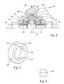
- FIG. 2is a partial sectional view of a first preferred embodiment of the differential gear assembly of the present invention including a first support ring with pins to secure pinion gears in engagement with a ring gear;
- FIG. 3is a perspective view of the support ring shown in FIG. 2 with the support ring haveing four holes for use in a differential gear assembly having four pinion gears;
- FIG. 4is a perspective view of the pin shown in FIG. 2;
- FIG. 5is a partial sectional exploded view showing the ring gear, a pinion gear, a pin and the first support ring;
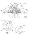
- FIG. 6is a partial sectional view of a second preferred embodiment of the differential gear assembly of the present invention including a second support ring which secures the pins within the holes of the first support ring;
- FIG. 7is an exploded view of the support rings.
- a differential assembly having a differential gear assembly of the present inventionis shown generally at 10 in FIG. 1 .
- the differential assembly 10includes a drive-shaft 12 which transfers rotational power from the engine of the vehicle to the differential assembly 10 .
- the drive-shaft 12includes an input gear 14 , such as a bevel gear, mounted at is end to engage a differential gear assembly 16 .
- FIG. 1only half of the differential gear assembly 16 is illustrated therein.
- the non-illustrated halfis, however, a mirror image of the illustrated half. Accordingly, those skilled in the field will readily appreciate the full construction of the gear assembly 16 without requiring such a full illustration.
- the differential gear assembly 16generally includes a differential housing 20 and a pair of side gears 22 which are substantially axially aligned and spaced apart from each other while being supported within the differential housing 20 .
- Each of the side gears 22is attached to an end of an axle half-shaft 18 of the vehicle.
- a plurality of pinion gears 24(one being shown), which are substantially axially aligned and spaced apart from each other, are supported within the differential housing 20 as explained hereinafter.
- Each of the pinion gears 24engages the side gears 22 .
- the pinion gears 24have an outwardly facing first side 26 and an inwardly facing second side 28 .
- the first side 26includes an outwardly extending projection 30 while the second side 28 includes a recess or hole 32 extending partially therethrough.
- the differential housing 20includes a pair of extending neck portions 34 , each of which are rotatably supporting a proximal end of one of the axle half-shafts 18 .
- the distal ends of each of the axle half-shafts 18are connected to a wheel of the vehicle.
- the proximal end of each of the axle half-shafts 18has secured thereon one of the side gears 22 , with the side gears 22 being engaged with the pinion gears 24 .
- rotation of the differential housing 20is transferred through the pinion gears 24 , to the side gears 22 and to the axle half-shafts 18 , all while allowing the axle half-shafts 18 to rotate relative to one another.
- a ring gear 36is mounted externally to the differential housing 20 .
- the ring gear 36is generally annularly shaped having a substantially circular inner surface and a plurality of circumferentially spaced teeth 38 extending obliquely from a side face of the ring gear 36 .
- the ring gear 36is a bevel ring gear.
- the teeth 38are adapted to provide smooth engagement with corresponding teeth on the input bevel gear 14 , which is mounted to of the drive shaft 12 of the vehicle.
- the ring gear 36further includes a plurality of recesses 40 spaced radially thereabout. Each of the recesses 40 receives the projection 30 extending from the first side 26 of one of the pinion gears 24 .
- Appropriate features, such as bearingsrotatably mount to the pinion gears 24 to the ring gear 36 for rotation about the projection 30 .
- the load from the drive-shaft 12is transferred directly from the ring gear 36 to the pinion gears 24 .
- the ring gear 36 and the pinion gears 24are formed from hardened steel, however it is to be understood that other materials with similar hardness and strength properties could be used with substantially equal results.
- a first support ring 42(FIGS. 1, 2 and 3 ) is placed between the pinion gears 24 to provide radial support for the pinion gears 24 and maintain engagement of the pinion gears 24 with the ring gear 36 .
- the first support ring 42has a plurality of holes 44 provided therein and extending therethrough. As shown in FIG. 3, the first support ring 42 has a total of four holes 44 , whereby one of the four holes 44 is aligned with the recesses 32 formed in the second side 28 of each of four pinion gears 24 used in the assembly 16 .
- the present inventioncould also be practiced with only two pinion gears 24 , whereby the first support ring 42 would only require two holes 44 therein.
- Pins 46are inserted within the holes 44 and extend into the recesses 32 to secure the pinion gears 24 to the first support ring 42 . Referring to FIG.
- an exploded view of the ring gear 36 , one of the pinion gears 24 , a dowel 46 and the first support ring 42more clearly illustrates the features of these components.
- the pins 46are held within the first support ring 42 by either press fitting of the pins 46 within the holes 44 or, alternatively, by welding the pins 46 within the holes 44 .
- the pins 46are held within the holes 44 of the first support ring 42 by a second support ring 48 .
- the second support ring 48has an out diameter approximately the inner diameter of the first support ring 42 and is not provided with any holes therethrough. As such, the ring 48 provides radial support for the pins 46 and keeps the pins 46 retained within the holes 44 of the first support ring 42 .
Landscapes
- Engineering & Computer Science (AREA)
- General Engineering & Computer Science (AREA)
- Mechanical Engineering (AREA)
- Retarders (AREA)
Abstract
Description
Claims (14)
Priority Applications (4)
| Application Number | Priority Date | Filing Date | Title |
|---|---|---|---|
| US10/062,073US6699154B2 (en) | 2002-01-31 | 2002-01-31 | Differential gear assembly |
| GB0300505AGB2386401B (en) | 2002-01-31 | 2003-01-10 | Differential gear assembly |
| FR0301067AFR2835302A1 (en) | 2002-01-31 | 2003-01-30 | DIFFERENTIAL SET |
| DE10304124ADE10304124B4 (en) | 2002-01-31 | 2003-01-31 | differential assembly |
Applications Claiming Priority (1)
| Application Number | Priority Date | Filing Date | Title |
|---|---|---|---|
| US10/062,073US6699154B2 (en) | 2002-01-31 | 2002-01-31 | Differential gear assembly |
Publications (2)
| Publication Number | Publication Date |
|---|---|
| US20030144107A1 US20030144107A1 (en) | 2003-07-31 |
| US6699154B2true US6699154B2 (en) | 2004-03-02 |
Family
ID=22040052
Family Applications (1)
| Application Number | Title | Priority Date | Filing Date |
|---|---|---|---|
| US10/062,073Expired - Fee RelatedUS6699154B2 (en) | 2002-01-31 | 2002-01-31 | Differential gear assembly |
Country Status (4)
| Country | Link |
|---|---|
| US (1) | US6699154B2 (en) |
| DE (1) | DE10304124B4 (en) |
| FR (1) | FR2835302A1 (en) |
| GB (1) | GB2386401B (en) |
Cited By (28)
| Publication number | Priority date | Publication date | Assignee | Title |
|---|---|---|---|---|
| US20060276296A1 (en)* | 2005-02-25 | 2006-12-07 | Ronjo Company, Llc. | Differential housing support member |
| US20060278036A1 (en)* | 2005-02-25 | 2006-12-14 | Ronjo Company, Llc. | Releasable enclosure for differential housing |
| US20060287155A1 (en)* | 2005-06-17 | 2006-12-21 | Jtekt Corporation | Differential Gearing for Vehicle |
| US20070095167A1 (en)* | 2005-10-21 | 2007-05-03 | Jtekt Corporation | Vehicle differential gear device, vehicle combined differential gear device and vehicle differential case |
| US20080261748A1 (en)* | 2007-04-18 | 2008-10-23 | Sudorowski Christopher M | Four pinion differential with cross pin retention unit and related method |
| US20080305910A1 (en)* | 2007-06-11 | 2008-12-11 | Ford Global Technologies, Llc | Dual-Pilot Axle Assembly for an Automotive Vehicle Driveline |
| US20090084223A1 (en)* | 2006-01-27 | 2009-04-02 | Clive James Harrup | Differential gear casing and method |
| US20090118054A1 (en)* | 2007-11-02 | 2009-05-07 | Jtekt Corporation | Differential apparatus for vehicle and assembling method thereof |
| US20090143183A1 (en)* | 2007-12-04 | 2009-06-04 | Jae-Hun Jung | Differential gear set in which lubrication structure is improved |
| US20090258750A1 (en)* | 2008-04-15 | 2009-10-15 | Ziech James F | Vehicle differential |
| US20090266198A1 (en)* | 2008-04-29 | 2009-10-29 | Transform Automotive Llc | Laser welded differential casings for vehicle axles |
| US20100130325A1 (en)* | 2007-05-08 | 2010-05-27 | Sona Blw Prazisionsschmiede Gmbh | Differential of lightweight construction for motor vehicles |
| US20100151983A1 (en)* | 2008-12-11 | 2010-06-17 | Ziech James F | Spider-less vehicle differential |
| US8043188B2 (en) | 2008-09-04 | 2011-10-25 | Dana Heavy Vehicle Systems Group, Llc | Spider-less vehicle differential |
| US20120000314A1 (en)* | 2010-07-01 | 2012-01-05 | Cripsey Timothy J | Flow-formed differential case assembly |
| US9028358B2 (en) | 2013-03-15 | 2015-05-12 | American Axle & Manufacturing, Inc. | Disconnecting axle assembly |
| US9157515B2 (en) | 2013-03-15 | 2015-10-13 | American Axle & Manufacturing, Inc. | Axle assembly |
| US9249872B2 (en) | 2013-03-15 | 2016-02-02 | American Axle & Manufacturing, Inc. | Axle assembly having an angular contact bearing that supports a ring gear for rotation on an axle housing |
| US9254713B2 (en) | 2013-03-15 | 2016-02-09 | American Axle & Manufacturing, Inc. | Axle assembly with inboard axle shaft bearings that support a differential mechanism |
| US9593757B2 (en) | 2013-03-15 | 2017-03-14 | American Axle & Manufacturing, Inc. | Axle assembly |
| US9797503B2 (en) | 2015-05-12 | 2017-10-24 | Caterpillar Inc. | Direct torque path differential having spiderless pinions |
| US9803736B2 (en) | 2015-05-12 | 2017-10-31 | Caterpillar Inc. | Direct torque path differential having spiderless pinions |
| US10082199B2 (en) | 2015-05-12 | 2018-09-25 | Caterpillar Inc. | Direct torque path differential having spiderless pinions |
| US10267401B2 (en) | 2015-11-25 | 2019-04-23 | American Axle & Manufacturing, Inc. | Axle assembly |
| US10487889B2 (en) | 2016-03-25 | 2019-11-26 | American Axle & Manufacturing, Inc. | Disconnecting axle assembly |
| US20200166111A1 (en)* | 2018-11-27 | 2020-05-28 | Musashi Seimitsu Industry Co., Ltd. | Differential device |
| US10704663B2 (en) | 2018-09-06 | 2020-07-07 | American Axle & Manufacturing, Inc. | Modular disconnecting drive module with torque vectoring augmentation |
| US10927937B2 (en) | 2018-09-06 | 2021-02-23 | American Axle & Manufacturing, Inc. | Modular disconnecting drive module with torque vectoring augmentation |
Families Citing this family (7)
| Publication number | Priority date | Publication date | Assignee | Title |
|---|---|---|---|---|
| GB2426798A (en)* | 2005-06-02 | 2006-12-06 | Sunpex Technology Co Ltd | Bearing arrangement supporting weight of differential gears on differential housing. |
| WO2008122276A2 (en)* | 2007-04-05 | 2008-10-16 | Neumayer Tekfor Holding Gmbh | Differential provided with a drive wheel |
| CN102518785A (en)* | 2011-12-30 | 2012-06-27 | 东风德纳车桥有限公司 | Main speed reducer housing for light car axle |
| CN103375569A (en)* | 2012-04-21 | 2013-10-30 | 东风德纳车桥有限公司 | Light speed reducer assembly |
| DE102014000430B4 (en)* | 2014-01-16 | 2017-07-13 | Audi Ag | differential gear |
| GB2521938A (en)* | 2014-12-11 | 2015-07-08 | Daimler Ag | Differential spider assembly for a differential gear of a vehicle, in particular a commercial vehicle |
| WO2023035232A1 (en)* | 2021-09-10 | 2023-03-16 | 舍弗勒技术股份两合公司 | Differential |
Citations (21)
| Publication number | Priority date | Publication date | Assignee | Title |
|---|---|---|---|---|
| US1230450A (en)* | 1913-06-06 | 1917-06-19 | Packard Motor Car Co | Motor-vehicle. |
| US1440555A (en)* | 1922-01-16 | 1923-01-02 | Advance Rumely Co | Differential for motor vehicles |
| US1657091A (en)* | 1927-07-23 | 1928-01-24 | Timken Axle Co Detroit | Differential mechanism |
| US3675459A (en) | 1971-02-03 | 1972-07-11 | Fritz Dohmann | Method for manufacturing bevel gears |
| US3741343A (en) | 1971-04-29 | 1973-06-26 | Clark Equipment Co | Lubrication system for a differential |
| US3874251A (en) | 1973-06-20 | 1975-04-01 | Igor Nikolaevich Lapitsky | Bevel gear differential |
| US4125026A (en) | 1974-12-02 | 1978-11-14 | Toyota Jidosha Kogyo Kabushiki Kaisha | Differential device for vehicles |
| US4688962A (en) | 1986-03-25 | 1987-08-25 | Deere & Company | No-slip shear connection |
| US4754661A (en) | 1985-06-15 | 1988-07-05 | Eaton Corporation | Limited slip differential |
| JPH02190655A (en)* | 1988-02-15 | 1990-07-26 | Sinberdis Christus | Gear box with continuous transmission leverage |
| US4949456A (en) | 1989-01-06 | 1990-08-21 | Eaton Corporation | Method of making ring gear and ring gear therefrom |
| US5098355A (en)* | 1990-12-05 | 1992-03-24 | Eaton Corporation | Floating ring gear and differential gear assembly |
| DE4042174A1 (en)* | 1990-12-29 | 1992-07-02 | Schmetz Roland Dipl Ing Dipl W | Differential gear with gear wheel - has equalising and drive shaft bevel gears with support in which is hole for bearings |
| US5480360A (en)* | 1993-04-23 | 1996-01-02 | Porsche | Differential for the axle drive of a motor vehicle |
| US5520589A (en) | 1993-10-14 | 1996-05-28 | Clark Equipment Company | Differential |
| US5584777A (en)* | 1994-05-18 | 1996-12-17 | Dr. Ing. H.C.F. Porsche Ag | Differential cage for absorbing shock mounted in a differential casing |
| JPH1061748A (en) | 1996-08-26 | 1998-03-06 | Kanzaki Kokyukoki Mfg Co Ltd | Differential gear device |
| US5823980A (en)* | 1996-09-20 | 1998-10-20 | Kopfer; Rudolph J. | Collapsible tactile support for body joints |
| US5980416A (en)* | 1997-08-06 | 1999-11-09 | Sven B. Gafvert | Differential for a vehicle |
| US6368242B1 (en)* | 2000-07-28 | 2002-04-09 | Spicer Technology, Inc. | Axle shaft retainer system |
| DE10136777A1 (en) | 2001-07-27 | 2003-02-13 | Zahnradfabrik Friedrichshafen | Differential for motor vehicles has crown wheel with compensation shaft and compensation wheels, and with support bearings |
Family Cites Families (2)
| Publication number | Priority date | Publication date | Assignee | Title |
|---|---|---|---|---|
| US1810194A (en)* | 1928-09-27 | 1931-06-16 | Columbia Axle Company | Differential mechanism |
| JPS6461748A (en)* | 1987-09-01 | 1989-03-08 | Fuji Photo Film Co Ltd | Silver halide photographic sensitive material |
- 2002
- 2002-01-31USUS10/062,073patent/US6699154B2/ennot_activeExpired - Fee Related
- 2003
- 2003-01-10GBGB0300505Apatent/GB2386401B/ennot_activeExpired - Fee Related
- 2003-01-30FRFR0301067Apatent/FR2835302A1/enactivePending
- 2003-01-31DEDE10304124Apatent/DE10304124B4/ennot_activeExpired - Fee Related
Patent Citations (21)
| Publication number | Priority date | Publication date | Assignee | Title |
|---|---|---|---|---|
| US1230450A (en)* | 1913-06-06 | 1917-06-19 | Packard Motor Car Co | Motor-vehicle. |
| US1440555A (en)* | 1922-01-16 | 1923-01-02 | Advance Rumely Co | Differential for motor vehicles |
| US1657091A (en)* | 1927-07-23 | 1928-01-24 | Timken Axle Co Detroit | Differential mechanism |
| US3675459A (en) | 1971-02-03 | 1972-07-11 | Fritz Dohmann | Method for manufacturing bevel gears |
| US3741343A (en) | 1971-04-29 | 1973-06-26 | Clark Equipment Co | Lubrication system for a differential |
| US3874251A (en) | 1973-06-20 | 1975-04-01 | Igor Nikolaevich Lapitsky | Bevel gear differential |
| US4125026A (en) | 1974-12-02 | 1978-11-14 | Toyota Jidosha Kogyo Kabushiki Kaisha | Differential device for vehicles |
| US4754661A (en) | 1985-06-15 | 1988-07-05 | Eaton Corporation | Limited slip differential |
| US4688962A (en) | 1986-03-25 | 1987-08-25 | Deere & Company | No-slip shear connection |
| JPH02190655A (en)* | 1988-02-15 | 1990-07-26 | Sinberdis Christus | Gear box with continuous transmission leverage |
| US4949456A (en) | 1989-01-06 | 1990-08-21 | Eaton Corporation | Method of making ring gear and ring gear therefrom |
| US5098355A (en)* | 1990-12-05 | 1992-03-24 | Eaton Corporation | Floating ring gear and differential gear assembly |
| DE4042174A1 (en)* | 1990-12-29 | 1992-07-02 | Schmetz Roland Dipl Ing Dipl W | Differential gear with gear wheel - has equalising and drive shaft bevel gears with support in which is hole for bearings |
| US5480360A (en)* | 1993-04-23 | 1996-01-02 | Porsche | Differential for the axle drive of a motor vehicle |
| US5520589A (en) | 1993-10-14 | 1996-05-28 | Clark Equipment Company | Differential |
| US5584777A (en)* | 1994-05-18 | 1996-12-17 | Dr. Ing. H.C.F. Porsche Ag | Differential cage for absorbing shock mounted in a differential casing |
| JPH1061748A (en) | 1996-08-26 | 1998-03-06 | Kanzaki Kokyukoki Mfg Co Ltd | Differential gear device |
| US5823980A (en)* | 1996-09-20 | 1998-10-20 | Kopfer; Rudolph J. | Collapsible tactile support for body joints |
| US5980416A (en)* | 1997-08-06 | 1999-11-09 | Sven B. Gafvert | Differential for a vehicle |
| US6368242B1 (en)* | 2000-07-28 | 2002-04-09 | Spicer Technology, Inc. | Axle shaft retainer system |
| DE10136777A1 (en) | 2001-07-27 | 2003-02-13 | Zahnradfabrik Friedrichshafen | Differential for motor vehicles has crown wheel with compensation shaft and compensation wheels, and with support bearings |
Cited By (48)
| Publication number | Priority date | Publication date | Assignee | Title |
|---|---|---|---|---|
| US7485064B2 (en) | 2005-02-25 | 2009-02-03 | Ronjo Company | Releasable enclosure for differential housing |
| US20060278036A1 (en)* | 2005-02-25 | 2006-12-14 | Ronjo Company, Llc. | Releasable enclosure for differential housing |
| US7367914B2 (en) | 2005-02-25 | 2008-05-06 | Ronjo Company | Differential housing support member |
| US20060276296A1 (en)* | 2005-02-25 | 2006-12-07 | Ronjo Company, Llc. | Differential housing support member |
| US20060287155A1 (en)* | 2005-06-17 | 2006-12-21 | Jtekt Corporation | Differential Gearing for Vehicle |
| US20070095167A1 (en)* | 2005-10-21 | 2007-05-03 | Jtekt Corporation | Vehicle differential gear device, vehicle combined differential gear device and vehicle differential case |
| US7749124B2 (en)* | 2005-10-21 | 2010-07-06 | Jtekt Corporation | Vehicle differential gear device, vehicle combined differential gear device and vehicle differential case |
| US8327541B2 (en)* | 2006-01-27 | 2012-12-11 | Meritor Heavy Vehicle Systems Cameri Spa | Method of assembling a differential mechanism |
| US20090084223A1 (en)* | 2006-01-27 | 2009-04-02 | Clive James Harrup | Differential gear casing and method |
| US7951037B2 (en) | 2007-04-18 | 2011-05-31 | American Axle & Manufacturing, Inc. | Four pinion differential with cross pin retention unit and related method |
| US20090305835A1 (en)* | 2007-04-18 | 2009-12-10 | American Axle & Manufacturing, Inc. | Four Pinion Differential With Cross Pin Retention Unit And Related Method |
| US7591751B2 (en)* | 2007-04-18 | 2009-09-22 | American Axle & Manufacturing, Inc. | Four pinion differential with cross pin retention unit and related method |
| US20080261748A1 (en)* | 2007-04-18 | 2008-10-23 | Sudorowski Christopher M | Four pinion differential with cross pin retention unit and related method |
| US20100130325A1 (en)* | 2007-05-08 | 2010-05-27 | Sona Blw Prazisionsschmiede Gmbh | Differential of lightweight construction for motor vehicles |
| US9683645B2 (en)* | 2007-05-08 | 2017-06-20 | Sona Blw Prazisionsschmiede Gmbh | Differential of lightweight construction for motor vehicles |
| US7878937B2 (en) | 2007-06-11 | 2011-02-01 | Ford Global Technologies, Llc | Dual-pilot axle assembly for an automotive vehicle driveline |
| US20080305910A1 (en)* | 2007-06-11 | 2008-12-11 | Ford Global Technologies, Llc | Dual-Pilot Axle Assembly for an Automotive Vehicle Driveline |
| US8216105B2 (en)* | 2007-11-02 | 2012-07-10 | Jtekt Corporation | Differential apparatus for vehicle and assembling method thereof |
| US20090118054A1 (en)* | 2007-11-02 | 2009-05-07 | Jtekt Corporation | Differential apparatus for vehicle and assembling method thereof |
| DE102008015694B4 (en)* | 2007-12-04 | 2013-05-29 | Hyundai Motor Co. | Differential gear with a lubrication structure |
| US20090143183A1 (en)* | 2007-12-04 | 2009-06-04 | Jae-Hun Jung | Differential gear set in which lubrication structure is improved |
| US7785222B2 (en)* | 2007-12-04 | 2010-08-31 | Hyundai Motor Company | Differential gear set in which lubrication structure is improved |
| US20090258750A1 (en)* | 2008-04-15 | 2009-10-15 | Ziech James F | Vehicle differential |
| US20090266198A1 (en)* | 2008-04-29 | 2009-10-29 | Transform Automotive Llc | Laser welded differential casings for vehicle axles |
| US8043188B2 (en) | 2008-09-04 | 2011-10-25 | Dana Heavy Vehicle Systems Group, Llc | Spider-less vehicle differential |
| US20100151983A1 (en)* | 2008-12-11 | 2010-06-17 | Ziech James F | Spider-less vehicle differential |
| US8628444B2 (en)* | 2010-07-01 | 2014-01-14 | Metal Forming & Coining Corporation | Flow-formed differential case assembly |
| US20120000314A1 (en)* | 2010-07-01 | 2012-01-05 | Cripsey Timothy J | Flow-formed differential case assembly |
| US9028358B2 (en) | 2013-03-15 | 2015-05-12 | American Axle & Manufacturing, Inc. | Disconnecting axle assembly |
| US9249872B2 (en) | 2013-03-15 | 2016-02-02 | American Axle & Manufacturing, Inc. | Axle assembly having an angular contact bearing that supports a ring gear for rotation on an axle housing |
| US9254713B2 (en) | 2013-03-15 | 2016-02-09 | American Axle & Manufacturing, Inc. | Axle assembly with inboard axle shaft bearings that support a differential mechanism |
| US9593757B2 (en) | 2013-03-15 | 2017-03-14 | American Axle & Manufacturing, Inc. | Axle assembly |
| US9677656B2 (en) | 2013-03-15 | 2017-06-13 | American Axle & Manufacturing, Inc. | Axle assembly |
| US9157515B2 (en) | 2013-03-15 | 2015-10-13 | American Axle & Manufacturing, Inc. | Axle assembly |
| US11473661B2 (en) | 2013-03-15 | 2022-10-18 | American Axle & Manufacturing, Inc. | Axle assembly |
| US10975945B2 (en) | 2013-03-15 | 2021-04-13 | American Axle & Manufacturing, Inc. | Axle assembly |
| US9895931B2 (en) | 2013-03-15 | 2018-02-20 | American Axle & Manufacturing, Inc. | Method for forming an axle shaft and related axle shaft |
| US11231096B2 (en) | 2013-03-15 | 2022-01-25 | American Axle & Manufacturing, Inc. | Axle assembly |
| US10166812B2 (en) | 2013-03-15 | 2019-01-01 | American Axle & Manufacturing, Inc. | Axle assembly |
| US9803736B2 (en) | 2015-05-12 | 2017-10-31 | Caterpillar Inc. | Direct torque path differential having spiderless pinions |
| US10082199B2 (en) | 2015-05-12 | 2018-09-25 | Caterpillar Inc. | Direct torque path differential having spiderless pinions |
| US9797503B2 (en) | 2015-05-12 | 2017-10-24 | Caterpillar Inc. | Direct torque path differential having spiderless pinions |
| US10267401B2 (en) | 2015-11-25 | 2019-04-23 | American Axle & Manufacturing, Inc. | Axle assembly |
| US10487889B2 (en) | 2016-03-25 | 2019-11-26 | American Axle & Manufacturing, Inc. | Disconnecting axle assembly |
| US10704663B2 (en) | 2018-09-06 | 2020-07-07 | American Axle & Manufacturing, Inc. | Modular disconnecting drive module with torque vectoring augmentation |
| US10927937B2 (en) | 2018-09-06 | 2021-02-23 | American Axle & Manufacturing, Inc. | Modular disconnecting drive module with torque vectoring augmentation |
| US20200166111A1 (en)* | 2018-11-27 | 2020-05-28 | Musashi Seimitsu Industry Co., Ltd. | Differential device |
| US10883587B2 (en)* | 2018-11-27 | 2021-01-05 | Musashi Seimitsu Industry Co., Ltd. | Differential device |
Also Published As
| Publication number | Publication date |
|---|---|
| DE10304124B4 (en) | 2006-01-12 |
| DE10304124A1 (en) | 2003-09-25 |
| US20030144107A1 (en) | 2003-07-31 |
| GB2386401B (en) | 2004-02-25 |
| FR2835302A1 (en) | 2003-08-01 |
| GB0300505D0 (en) | 2003-02-12 |
| GB2386401A (en) | 2003-09-17 |
Similar Documents
| Publication | Publication Date | Title |
|---|---|---|
| US6699154B2 (en) | Differential gear assembly | |
| US6623396B2 (en) | Differential gear assembly | |
| US6743138B2 (en) | Compact differential housing assembly | |
| US7306537B2 (en) | Differential gearing for vehicle | |
| US6645113B2 (en) | Differential gear retention system | |
| EP1571373A2 (en) | Helical gear differential | |
| US6813972B2 (en) | Differential housing assembly with cap-ring bearing support architecture | |
| US6659651B1 (en) | Driving and locking mechanism for a threaded bearing cup | |
| WO2004013519A1 (en) | Differential gear for vehicle | |
| US5785624A (en) | Differential drive with supporting means for differential gears | |
| US6013004A (en) | Parallel-axis gear differential with pinion mounted brake shoes | |
| WO2007109572A2 (en) | Adjustable antifriction bearing arrangement | |
| US6811511B2 (en) | Gearwheel pairing and its use | |
| JP2008051305A (en) | Vehicle differential case and vehicle differential equipped with the same | |
| JP2008082544A (en) | Vehicle differential | |
| JP3284065B2 (en) | Planetary gear reducer | |
| JP3574273B2 (en) | Axle drive for traveling vehicles | |
| US5662544A (en) | Side gear retention of pinion mates | |
| WO2009012792A1 (en) | A differential housing and a crown for a differential gearbox in a vehicle | |
| JP2004068873A (en) | Pinion washer | |
| JP2008051301A (en) | Vehicle differential case and vehicle differential equipped with the same | |
| EP1623128A1 (en) | Annular member and drive device comprising the annular member | |
| JP4715005B2 (en) | Rolling bearing unit for drive wheels | |
| JPH11166524A (en) | Rolling bearing unit for wheels | |
| JPS58137646A (en) | Differential locking apparatus for automobile |
Legal Events
| Date | Code | Title | Description |
|---|---|---|---|
| AS | Assignment | Owner name:VISTEON GLOBAL TECHNOLOGIES, INC., MICHIGAN Free format text:ASSIGNMENT OF ASSIGNORS INTEREST;ASSIGNORS:ORR, BRIAN CHRISTIAN;KRZESICKI, RICHARD MICHAEL;RUTT, JOHN EDWARD;REEL/FRAME:012789/0496;SIGNING DATES FROM 20020315 TO 20020318 | |
| AS | Assignment | Owner name:AUTOMOTIVE COMPONENTS HOLDINGS, LLC, MICHIGAN Free format text:ASSIGNMENT OF ASSIGNORS INTEREST;ASSIGNOR:VISTEON GLOBAL TECHNOLOGIES, INC.;REEL/FRAME:016835/0471 Effective date:20051129 | |
| AS | Assignment | Owner name:FORD MOTOR COMPANY, MICHIGAN Free format text:ASSIGNMENT OF ASSIGNORS INTEREST;ASSIGNOR:AUTOMOTIVE COMPONENTS HOLDINGS, LLC;REEL/FRAME:017164/0694 Effective date:20060214 | |
| FPAY | Fee payment | Year of fee payment:4 | |
| AS | Assignment | Owner name:FORD GLOBAL TECHNOLOGIES, LLC, MICHIGAN Free format text:ASSIGNMENT OF ASSIGNORS INTEREST;ASSIGNOR:FORD MOTOR COMPANY;REEL/FRAME:022562/0494 Effective date:20090414 Owner name:FORD GLOBAL TECHNOLOGIES, LLC,MICHIGAN Free format text:ASSIGNMENT OF ASSIGNORS INTEREST;ASSIGNOR:FORD MOTOR COMPANY;REEL/FRAME:022562/0494 Effective date:20090414 | |
| FPAY | Fee payment | Year of fee payment:8 | |
| REMI | Maintenance fee reminder mailed | ||
| LAPS | Lapse for failure to pay maintenance fees | ||
| STCH | Information on status: patent discontinuation | Free format text:PATENT EXPIRED DUE TO NONPAYMENT OF MAINTENANCE FEES UNDER 37 CFR 1.362 | |
| FP | Lapsed due to failure to pay maintenance fee | Effective date:20160302 |