US6698228B2 - Method and apparatus for producing and dispensing an aerated and/or blended food product - Google Patents
Method and apparatus for producing and dispensing an aerated and/or blended food productDownload PDFInfo
- Publication number
- US6698228B2 US6698228B2US10/160,674US16067402AUS6698228B2US 6698228 B2US6698228 B2US 6698228B2US 16067402 AUS16067402 AUS 16067402AUS 6698228 B2US6698228 B2US 6698228B2
- Authority
- US
- United States
- Prior art keywords
- rotary surface
- product
- rotating
- rotary
- depositing
- Prior art date
- Legal status (The legal status is an assumption and is not a legal conclusion. Google has not performed a legal analysis and makes no representation as to the accuracy of the status listed.)
- Expired - Fee Related
Links
- 235000013305foodNutrition0.000titleclaimsdescription27
- 238000000034methodMethods0.000titleabstractdescription11
- 239000000047productSubstances0.000claimsabstractdescription188
- 238000000151depositionMethods0.000claimsabstractdescription40
- 239000012263liquid productSubstances0.000claimsabstractdescription39
- 238000007790scrapingMethods0.000claimsabstractdescription38
- 239000007787solidSubstances0.000claimsabstractdescription8
- 239000000203mixtureSubstances0.000claimsdescription59
- 239000012530fluidSubstances0.000claimsdescription41
- 238000002156mixingMethods0.000claimsdescription22
- 230000033001locomotionEffects0.000claimsdescription12
- 238000005273aerationMethods0.000claimsdescription4
- 230000015572biosynthetic processEffects0.000claimsdescription4
- 238000001816coolingMethods0.000claimsdescription4
- 230000008093supporting effectEffects0.000claimsdescription2
- 238000007710freezingMethods0.000abstractdescription90
- 230000008014freezingEffects0.000abstractdescription90
- 239000007788liquidSubstances0.000abstractdescription30
- 235000013611frozen foodNutrition0.000abstractdescription3
- 239000000796flavoring agentSubstances0.000description33
- 235000019634flavorsNutrition0.000description33
- 238000004140cleaningMethods0.000description29
- 235000015243ice creamNutrition0.000description23
- 239000003507refrigerantSubstances0.000description18
- 238000005057refrigerationMethods0.000description18
- 238000000429assemblyMethods0.000description13
- 230000000712assemblyEffects0.000description13
- 230000008878couplingEffects0.000description12
- 238000010168coupling processMethods0.000description12
- 238000005859coupling reactionMethods0.000description12
- 230000006870functionEffects0.000description11
- 239000004615ingredientSubstances0.000description10
- 239000002699waste materialSubstances0.000description9
- XLYOFNOQVPJJNP-UHFFFAOYSA-NwaterSubstancesOXLYOFNOQVPJJNP-UHFFFAOYSA-N0.000description9
- 235000019219chocolateNutrition0.000description8
- 235000013618yogurtNutrition0.000description8
- 238000005086pumpingMethods0.000description7
- 235000009508confectioneryNutrition0.000description6
- 238000012423maintenanceMethods0.000description6
- 238000005056compactionMethods0.000description4
- 230000008569processEffects0.000description4
- 238000013022ventingMethods0.000description4
- DNIAPMSPPWPWGF-UHFFFAOYSA-NPropylene glycolChemical compoundCC(O)CODNIAPMSPPWPWGF-UHFFFAOYSA-N0.000description3
- 244000290333Vanilla fragransSpecies0.000description3
- 235000009499Vanilla fragransNutrition0.000description3
- 235000012036Vanilla tahitensisNutrition0.000description3
- 235000016213coffeeNutrition0.000description3
- 235000013353coffee beverageNutrition0.000description3
- 235000014510cookyNutrition0.000description3
- 230000000881depressing effectEffects0.000description3
- 230000000694effectsEffects0.000description3
- 238000004519manufacturing processMethods0.000description3
- 235000003363Cornus masNutrition0.000description2
- 240000006766Cornus masSpecies0.000description2
- 235000016623Fragaria vescaNutrition0.000description2
- 240000009088Fragaria x ananassaSpecies0.000description2
- 235000011363Fragaria x ananassaNutrition0.000description2
- 230000003213activating effectEffects0.000description2
- 230000008901benefitEffects0.000description2
- 235000013361beverageNutrition0.000description2
- 230000008859changeEffects0.000description2
- 238000004891communicationMethods0.000description2
- 238000010276constructionMethods0.000description2
- 235000013365dairy productNutrition0.000description2
- 238000009826distributionMethods0.000description2
- 238000011049fillingMethods0.000description2
- ZZUFCTLCJUWOSV-UHFFFAOYSA-NfurosemideChemical compoundC1=C(Cl)C(S(=O)(=O)N)=CC(C(O)=O)=C1NCC1=CC=CO1ZZUFCTLCJUWOSV-UHFFFAOYSA-N0.000description2
- 230000007246mechanismEffects0.000description2
- 239000008267milkSubstances0.000description2
- 235000013336milkNutrition0.000description2
- 210000004080milkAnatomy0.000description2
- 239000003595mistSubstances0.000description2
- 230000037361pathwayEffects0.000description2
- 230000002441reversible effectEffects0.000description2
- 235000015067saucesNutrition0.000description2
- 235000014347soupsNutrition0.000description2
- 241000208140AcerSpecies0.000description1
- 244000291564Allium cepaSpecies0.000description1
- 235000002732Allium cepa var. cepaNutrition0.000description1
- 241000894006BacteriaSpecies0.000description1
- 235000002566CapsicumNutrition0.000description1
- 235000013162Cocos nuciferaNutrition0.000description1
- 244000060011Cocos nuciferaSpecies0.000description1
- 235000010469Glycine maxNutrition0.000description1
- 240000008790Musa x paradisiacaSpecies0.000description1
- 235000018290Musa x paradisiacaNutrition0.000description1
- 241000758706PiperaceaeSpecies0.000description1
- 241001291279Solanum galapagenseSpecies0.000description1
- 244000269722Thea sinensisSpecies0.000description1
- 230000002411adverseEffects0.000description1
- 230000000903blocking effectEffects0.000description1
- 239000006227byproductSubstances0.000description1
- 235000013351cheeseNutrition0.000description1
- 239000003638chemical reducing agentSubstances0.000description1
- 239000008370chocolate flavorSubstances0.000description1
- 235000020965cold beverageNutrition0.000description1
- 235000021270cold foodNutrition0.000description1
- 239000013078crystalSubstances0.000description1
- 238000002425crystallisationMethods0.000description1
- 230000008025crystallizationEffects0.000description1
- 230000001351cycling effectEffects0.000description1
- 230000000994depressogenic effectEffects0.000description1
- 238000013461designMethods0.000description1
- 239000003599detergentSubstances0.000description1
- 238000010586diagramMethods0.000description1
- 230000003670easy-to-cleanEffects0.000description1
- 235000013861fat-freeNutrition0.000description1
- 210000003608feceAnatomy0.000description1
- 239000012467final productSubstances0.000description1
- 235000011389fruit/vegetable juiceNutrition0.000description1
- 238000002309gasificationMethods0.000description1
- 210000004907glandAnatomy0.000description1
- 230000036541healthEffects0.000description1
- 238000010438heat treatmentMethods0.000description1
- 235000012171hot beverageNutrition0.000description1
- 235000020278hot chocolateNutrition0.000description1
- 235000021268hot foodNutrition0.000description1
- 230000001976improved effectEffects0.000description1
- 230000000977initiatory effectEffects0.000description1
- 235000014109instant soupNutrition0.000description1
- 230000000670limiting effectEffects0.000description1
- 235000021056liquid foodNutrition0.000description1
- 238000011068loading methodMethods0.000description1
- 239000000463materialSubstances0.000description1
- 230000007935neutral effectEffects0.000description1
- 235000019629palatabilityNutrition0.000description1
- 235000012771pancakesNutrition0.000description1
- 239000002245particleSubstances0.000description1
- 230000002572peristaltic effectEffects0.000description1
- 239000000843powderSubstances0.000description1
- 238000002360preparation methodMethods0.000description1
- 238000012545processingMethods0.000description1
- 230000002035prolonged effectEffects0.000description1
- 230000001681protective effectEffects0.000description1
- 235000011962puddingsNutrition0.000description1
- 230000002829reductive effectEffects0.000description1
- 230000002040relaxant effectEffects0.000description1
- 239000011369resultant mixtureSubstances0.000description1
- 230000000717retained effectEffects0.000description1
- 239000002002slurrySubstances0.000description1
- 235000014214soft drinkNutrition0.000description1
- 125000006850spacer groupChemical group0.000description1
- 230000007480spreadingEffects0.000description1
- 238000003892spreadingMethods0.000description1
- 239000000126substanceSubstances0.000description1
- 239000006188syrupSubstances0.000description1
- 235000020357syrupNutrition0.000description1
- 235000013616teaNutrition0.000description1
- 210000003813thumbAnatomy0.000description1
- 238000012546transferMethods0.000description1
Images


Classifications
- G—PHYSICS
- G07—CHECKING-DEVICES
- G07F—COIN-FREED OR LIKE APPARATUS
- G07F17/00—Coin-freed apparatus for hiring articles; Coin-freed facilities or services
- G07F17/0064—Coin-freed apparatus for hiring articles; Coin-freed facilities or services for processing of food articles
- G07F17/0071—Food articles which need to be processed for dispensing in a cold condition, e.g. ice and ice cream
- A—HUMAN NECESSITIES
- A23—FOODS OR FOODSTUFFS; TREATMENT THEREOF, NOT COVERED BY OTHER CLASSES
- A23G—COCOA; COCOA PRODUCTS, e.g. CHOCOLATE; SUBSTITUTES FOR COCOA OR COCOA PRODUCTS; CONFECTIONERY; CHEWING GUM; ICE-CREAM; PREPARATION THEREOF
- A23G9/00—Frozen sweets, e.g. ice confectionery, ice-cream; Mixtures therefor
- A23G9/04—Production of frozen sweets, e.g. ice-cream
- A23G9/045—Production of frozen sweets, e.g. ice-cream of slush-ice, e.g. semi-frozen beverage
- A—HUMAN NECESSITIES
- A23—FOODS OR FOODSTUFFS; TREATMENT THEREOF, NOT COVERED BY OTHER CLASSES
- A23G—COCOA; COCOA PRODUCTS, e.g. CHOCOLATE; SUBSTITUTES FOR COCOA OR COCOA PRODUCTS; CONFECTIONERY; CHEWING GUM; ICE-CREAM; PREPARATION THEREOF
- A23G9/00—Frozen sweets, e.g. ice confectionery, ice-cream; Mixtures therefor
- A23G9/04—Production of frozen sweets, e.g. ice-cream
- A23G9/14—Continuous production
- A23G9/16—Continuous production the products being within a cooled chamber, e.g. drum
- A23G9/163—Continuous production the products being within a cooled chamber, e.g. drum with intermittent operation
- A—HUMAN NECESSITIES
- A23—FOODS OR FOODSTUFFS; TREATMENT THEREOF, NOT COVERED BY OTHER CLASSES
- A23G—COCOA; COCOA PRODUCTS, e.g. CHOCOLATE; SUBSTITUTES FOR COCOA OR COCOA PRODUCTS; CONFECTIONERY; CHEWING GUM; ICE-CREAM; PREPARATION THEREOF
- A23G9/00—Frozen sweets, e.g. ice confectionery, ice-cream; Mixtures therefor
- A23G9/04—Production of frozen sweets, e.g. ice-cream
- A23G9/20—Production of frozen sweets, e.g. ice-cream the products being mixed with gas, e.g. soft-ice
- A—HUMAN NECESSITIES
- A23—FOODS OR FOODSTUFFS; TREATMENT THEREOF, NOT COVERED BY OTHER CLASSES
- A23G—COCOA; COCOA PRODUCTS, e.g. CHOCOLATE; SUBSTITUTES FOR COCOA OR COCOA PRODUCTS; CONFECTIONERY; CHEWING GUM; ICE-CREAM; PREPARATION THEREOF
- A23G9/00—Frozen sweets, e.g. ice confectionery, ice-cream; Mixtures therefor
- A23G9/04—Production of frozen sweets, e.g. ice-cream
- A23G9/22—Details, component parts or accessories of apparatus insofar as not peculiar to a single one of the preceding groups
- A23G9/228—Arrangement and mounting of control or safety devices
- A—HUMAN NECESSITIES
- A23—FOODS OR FOODSTUFFS; TREATMENT THEREOF, NOT COVERED BY OTHER CLASSES
- A23G—COCOA; COCOA PRODUCTS, e.g. CHOCOLATE; SUBSTITUTES FOR COCOA OR COCOA PRODUCTS; CONFECTIONERY; CHEWING GUM; ICE-CREAM; PREPARATION THEREOF
- A23G9/00—Frozen sweets, e.g. ice confectionery, ice-cream; Mixtures therefor
- A23G9/04—Production of frozen sweets, e.g. ice-cream
- A23G9/22—Details, component parts or accessories of apparatus insofar as not peculiar to a single one of the preceding groups
- A23G9/28—Details, component parts or accessories of apparatus insofar as not peculiar to a single one of the preceding groups for portioning or dispensing
- A23G9/281—Details, component parts or accessories of apparatus insofar as not peculiar to a single one of the preceding groups for portioning or dispensing at the discharge end of freezing chambers
- A23G9/282—Details, component parts or accessories of apparatus insofar as not peculiar to a single one of the preceding groups for portioning or dispensing at the discharge end of freezing chambers for dispensing multi-flavour ice-creams
- A—HUMAN NECESSITIES
- A23—FOODS OR FOODSTUFFS; TREATMENT THEREOF, NOT COVERED BY OTHER CLASSES
- A23G—COCOA; COCOA PRODUCTS, e.g. CHOCOLATE; SUBSTITUTES FOR COCOA OR COCOA PRODUCTS; CONFECTIONERY; CHEWING GUM; ICE-CREAM; PREPARATION THEREOF
- A23G9/00—Frozen sweets, e.g. ice confectionery, ice-cream; Mixtures therefor
- A23G9/04—Production of frozen sweets, e.g. ice-cream
- A23G9/22—Details, component parts or accessories of apparatus insofar as not peculiar to a single one of the preceding groups
- A23G9/28—Details, component parts or accessories of apparatus insofar as not peculiar to a single one of the preceding groups for portioning or dispensing
- A23G9/281—Details, component parts or accessories of apparatus insofar as not peculiar to a single one of the preceding groups for portioning or dispensing at the discharge end of freezing chambers
- A23G9/283—Details, component parts or accessories of apparatus insofar as not peculiar to a single one of the preceding groups for portioning or dispensing at the discharge end of freezing chambers for filling containers with material
- A—HUMAN NECESSITIES
- A23—FOODS OR FOODSTUFFS; TREATMENT THEREOF, NOT COVERED BY OTHER CLASSES
- A23G—COCOA; COCOA PRODUCTS, e.g. CHOCOLATE; SUBSTITUTES FOR COCOA OR COCOA PRODUCTS; CONFECTIONERY; CHEWING GUM; ICE-CREAM; PREPARATION THEREOF
- A23G9/00—Frozen sweets, e.g. ice confectionery, ice-cream; Mixtures therefor
- A23G9/44—Frozen sweets, e.g. ice confectionery, ice-cream; Mixtures therefor characterised by shape, structure or physical form
- A23G9/46—Aerated, foamed, cellular or porous products
- A—HUMAN NECESSITIES
- A23—FOODS OR FOODSTUFFS; TREATMENT THEREOF, NOT COVERED BY OTHER CLASSES
- A23G—COCOA; COCOA PRODUCTS, e.g. CHOCOLATE; SUBSTITUTES FOR COCOA OR COCOA PRODUCTS; CONFECTIONERY; CHEWING GUM; ICE-CREAM; PREPARATION THEREOF
- A23G9/00—Frozen sweets, e.g. ice confectionery, ice-cream; Mixtures therefor
- A23G9/44—Frozen sweets, e.g. ice confectionery, ice-cream; Mixtures therefor characterised by shape, structure or physical form
- A23G9/48—Composite products, e.g. layered, laminated, coated, filled
- F—MECHANICAL ENGINEERING; LIGHTING; HEATING; WEAPONS; BLASTING
- F25—REFRIGERATION OR COOLING; COMBINED HEATING AND REFRIGERATION SYSTEMS; HEAT PUMP SYSTEMS; MANUFACTURE OR STORAGE OF ICE; LIQUEFACTION SOLIDIFICATION OF GASES
- F25B—REFRIGERATION MACHINES, PLANTS OR SYSTEMS; COMBINED HEATING AND REFRIGERATION SYSTEMS; HEAT PUMP SYSTEMS
- F25B41/00—Fluid-circulation arrangements
- F25B41/20—Disposition of valves, e.g. of on-off valves or flow control valves
- F25B41/22—Disposition of valves, e.g. of on-off valves or flow control valves between evaporator and compressor
- F—MECHANICAL ENGINEERING; LIGHTING; HEATING; WEAPONS; BLASTING
- F25—REFRIGERATION OR COOLING; COMBINED HEATING AND REFRIGERATION SYSTEMS; HEAT PUMP SYSTEMS; MANUFACTURE OR STORAGE OF ICE; LIQUEFACTION SOLIDIFICATION OF GASES
- F25C—PRODUCING, WORKING OR HANDLING ICE
- F25C1/00—Producing ice
- F25C1/12—Producing ice by freezing water on cooled surfaces, e.g. to form slabs
- F25C1/14—Producing ice by freezing water on cooled surfaces, e.g. to form slabs to form thin sheets which are removed by scraping or wedging, e.g. in the form of flakes
- F25C1/145—Producing ice by freezing water on cooled surfaces, e.g. to form slabs to form thin sheets which are removed by scraping or wedging, e.g. in the form of flakes from the inner walls of cooled bodies
Definitions
- This inventionrelates to a method and apparatus for producing and dispensing aerated and/or blended food products. While the invention may be used to produce a variety of products, it has particular application to the production and dispensing of frozen confections such as ice cream and frozen yogurt. Consequently, we will describe the invention in that context. It should be understood, however, that various aspects of the invention to be described also have application to the making and dispensing of various other food products.
- Aerated frozen food productsgenerally require the mixing of selected liquid ingredients with a prescribed volume of air and freezing of the resultant mixture and dispensing of the finished product.
- the desirability of the finished productis often related directly to the manner and to the degree in which the air is metered and blended with the liquid ingredients of the mixture, referred to as overrun, and the manner in which the blended mix is frozen and then dispensed.
- the prior artis replete with examples of apparatus for dispensing ice cream and other semi-frozen dairy products such as soft ice cream and frozen yogurt.
- Such machinesare usually dedicated to dispensing one or two flavors of product and, in some cases, a combination of the two.
- a machinewith two separate freezing chambers for making and dispensing chocolate and vanilla ice cream, a second two-chamber machine for making and dispensing strawberry and banana ice cream, a third machine dedicated to making and dispensing coffee and frozen pudding flavors, and so on.
- each chambertypically contains a volume of ice cream greater than is required for a single serving. In order to dispense a different flavor ice cream, that chamber must be emptied and cleaned before the new flavor can be made in that chamber and appear at the outlet of the dispenser.
- vat of preflavored mix from which the frozen product is mademust also be very clean. While high volume ice cream shops and confectionery stores may have sales to justify the presence of several dispensing machines dispensing many different products and flavors, smaller sales outlets can usually only afford one or two such machines and are thus restricted in the number of flavors that they can offer to customers.
- the productis typically formed in a quantity that is greater than that to be dispensed at any one serving, the excess product remains in the chamber after formation and until additional servings draw it down. The excess is thus subjected to further freezing which promotes crystallization. Because of the relatively large quantity of the premixed flavors, and the continuous freezing of several quarts of the product, the freshness and palatability of the product may be adversely affected in outlets with relatively slow sales of the product.
- U.S. Pat. No. 5,433,967discloses a method and apparatus for producing and dispensing an aerated product which includes a mixing chamber having a first inlet for receiving a liquid, a second inlet for receiving a gas, and an outlet leading to a continuous tube which has a relatively small cross section.
- the tubehas one end positioned to receive the fluid effluent from the mixing chamber outlet and its other end is spaced from that outlet so that the effluent is subjected to confined turbulent mixing in the tube until the fluid product is discharged from the other end of the tube. If that product is to be cooled, the tube leads to a cooling zone or surface which cools and at least partially freezes the liquid product issuing from that tube.
- the apparatus disclosed thereis especially suitable for making and dispensing frozen yogurt and ice cream and allows for the service of individualized fresh product portions in a variety of flavors.
- U.S. Pat. No. 5,727,713discloses a dispenser product supply unit which includes a pressurizable container for containing a product liquid or base and having an opening leading into one end of a conduit. Formed integrally in the conduit is a mixing chamber at which a gas may be added to the liquid, followed by an elongated tube for causing turbulent flow of the mixed fluids. Side branches from the conduit may also be present for introducing one or more flavors into the fluid flowing through the conduit. The opposite or outlet end of the conduit may be coupled to a distribution manifold that can distribute the aerated liquid issuing from the turbulence tube onto a freezing surface as a relatively thin layer.
- the container, conduit and side branchesconstitute a one-piece disposable structure which is especially suitable for producing and dispensing flavored dairy products from an associated dispensing apparatus in an efficient and sanitary manner.
- Another object of the inventionis to provide apparatus for producing and dispensing various food products which does not require the maintenance of a large supply of preflavored mixes and/or a large supply of finished product within the apparatus.
- Still another object in the inventionis to provide such apparatus which facilitates changing substantially immediately from one product type to another to satisfy the demands of individual customers.
- a further object of the inventionis to provide apparatus for producing and dispensing individualized portions of freshly aerated flavored frozen products on demand and in different formats, e.g. as a cup or cone.
- Yet another object of the inventionis to provide apparatus for producing and dispensing aerated frozen products which is easy to clean and to maintain in a sanitary condition.
- Another objectis to provide apparatus for selectively mixing or blending many different flavors while aerating a base product such as a neutral ice cream, fat-free ice cream, soy, sorbet or yogurt base.
- a base productsuch as a neutral ice cream, fat-free ice cream, soy, sorbet or yogurt base.
- An additional objectis to provide a frozen product-dispensing machine which has a minimal product carryover from one serving to the next, e.g. which prevents a serving of vanilla ice cream from being contaminated by residue from a prior serving of chocolate ice cream.
- a further object of the inventionis provide apparatus for this general type which occupies a relatively small amount of floor space while being able to dispense food products having a wide variety of bases, flavors and mix-ins.
- Still another object of the inventionis to provide apparatus of this type which maintains the product supply under sanitary conditions until it is dispensed.
- a further object of the inventionis to provide apparatus for effectively and efficiently carrying out the dispensing methods disclosed in the above patents.
- Yet another object of the inventionis to provide a method of producing and dispensing various food products which produces one or more of the above advantages.
- our product dispensing apparatusis preferably a self-contained unit housed in a cabinet having a door containing a product selection control panel and a portal providing access to a product dispensing station including a vertically moveable tray which can support a product container such as a cup or cone placed on the tray.
- the apparatusincludes a rotary horizontal freezing surface and motive means for rotating that surface about an axis.
- the freezing surfaceconstitutes the evaporator component of a closed-loop refrigeration system situated in the cabinet. When the refrigeration system is in operation, it maintains the surface of the freezing surface at a selected temperature which is low enough to freeze or partially freeze a liquid product mix such as sorbet, yogurt or ice cream mix deposited on that surface.
- a turret sectionSpaced above the freezing surface is a turret section including a turret having a plurality of pumpable containers filled with different liquid flavors and supported on a rotary manifold.
- the manifolddefines a plurality of mixing chambers, one for each container, and a separate turbulence tube leading from each mixing chamber to a separate outlet port in a depositing head over the freezing surface.
- Each containeris connected to one of the mixing chambers of the manifold and motive means are provided for rotating the turret independently of the freezing surface, about an axis located above the freezing surface.
- product base delivery meansincluding one or more vertically moveable nozzles or fittings each of which receives compressed air and a different one of a plurality of liquid product bases pumped thereto from bulk supplies stored in the cabinet.
- Each of the aforesaid nozzleswhen operative, may deliver to the turret a liquid product base along with air (or not).
- the selected product base with or without air delivered by a nozzleis brought together with the selected flavor pumped from a flavor container.
- the two fluidsare then intimately mixed together in the manifold and conducted to the manifold's depositing head so that a fixed volume or portion of the selected flavored and aerated (or not) product mix is deposited on the freezing surface.
- the apparatusalso comprises a stationary product delivery section disposed between the turret section and the freezing surface.
- the delivery sectionhas product mix leveling means in the form of a radially oriented self-cleaning roller having a conical surface spaced above the freezing surface.
- product mix leveling meansin the form of a radially oriented self-cleaning roller having a conical surface spaced above the freezing surface.
- the delivery sectionalso includes a radial scraper angularly spaced behind the roller which scrapes the layer of frozen product from the rotating freezing surface and gathers it into a radially extending ridge row of frozen scrapings which row is aligned with a vertically oriented forming cylinder located at the periphery of the delivery section just beyond the edge of the freezing surface.
- the delivery sectionalso has a radially moveable scraping blade which operates in conjunction with the radial scraper to push the ridge row of frozen product through a side window of the forming cylinder to gather and compress the frozen product within that cylinder.
- a radially moveable scraping bladewhich operates in conjunction with the radial scraper to push the ridge row of frozen product through a side window of the forming cylinder to gather and compress the frozen product within that cylinder.
- a piston moveable along the cylinderto further compact the product into a scoop shape and push the scoop of frozen product out the bottom of the cylinder into a container, e.g. a cup or cone, which has been placed on the tray at the product dispensing station and raised to position the container at a selected elevation under the forming cylinder.
- the trayis lowered so that the container may be removed from the tray through the portal in the cabinet door.
- the apparatusis designed so that all critical components of the apparatus are readily accessible for cleaning and routine maintenance.
- the present apparatusis able to efficiently and effectively dispense, on demand, a variety of food products for a prolonged period of time and requires only a minimum amount of maintenance.
- FIG. 1is a perspective view of dispensing apparatus incorporating the invention with the front door of the apparatus shown partially open;
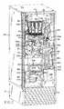
- FIG. 2is a similar view of the FIG. 1 apparatus on a slightly larger scale with the front door removed and with the apparatus' turret section and delivery section shown in their closed positions;
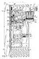
- FIG. 3is a similar view of the apparatus with its turret section shown in the open position and the delivery gate cover removed;
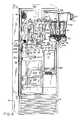
- FIG. 4is a similar view of the apparatus showing both the turret section and delivery sections (sans cover) in their open positions;
- FIG. 5is a right front perspective view of the FIG. 1 apparatus devoid of the cabinet and other parts;
- FIG. 6Ais a fragmentary perspective view on a larger scale showing part of the turret section of the FIG. 1 apparatus in greater detail;
- FIG. 6Bis a sectional view on a larger scale showing in detail a flavor bottle pump in the FIG. 6A turret section;
- FIG. 6Cis a fragmentary perspective view showing the underside of the turret section
- FIG. 6Dis a sectional view on a larger scale taken along line 6 D— 6 D of FIG. 6A.;
- FIG. 7is an enlarged perspective view showing the leveling roller in the delivery section of the FIG. 1 apparatus
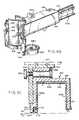
- FIG. 8Ais a perspective view from below illustrating the compaction/forming assembly in the delivery section of the FIG. 1 apparatus
- FIG. 8Bis a similar view from above of a portion of that assembly
- FIG. 8Cis a sectional view on a larger scale taken along line 8 C— 8 C of FIG. 8A;
- FIG. 8Dis a fragmentary perspective view showing another portion of the delivery section in greater detail
- FIG. 8Eis a fragmentary sectional view, on a larger scale, showing a part of the FIG. 8A assembly in greater detail;
- FIG. 9is a diagrammatic view of another part of the delivery section.
- FIG. 10is a sectional view on a larger scale taken along line 10 — 10 of FIG. 4;
- FIG. 11is a block diagram of the refrigeration loop in the FIG. 1 apparatus
- FIG. 12Ais a sectional view on a larger scale of the rotary coupling/seal assembly for the rotary freezing surface in the FIG. 1 apparatus, and
- FIG. 12Bis a similar view on a much smaller scale of another such assembly embodiment.
- our dispensing apparatusis a stand-alone unit housed in a cabinet 10 having a top wall 10 a , opposite sidewalls 10 b and 10 c as well as rear and bottom walls (not shown).
- the front of the cabinetis open for the most part except for a low front wall 12 containing louvers to provide inlet air to the primary refrigeration unit.
- the front opening into the cabinetmay be closed by a hinged door 14 which may be swung between an open position wherein the door allows access to the interior of the cabinet and a closed position wherein the door covers the opening into the cabinet.
- Suitable means 15 a , 15 bare provided for latching or locking the door in it's closed position.
- a relatively large opening or portal 16is provided in door 14 so that when the door is closed, the portal 16 provides access to a dispensing station 17 within the cabinet at which a customer may pick up a food product dispensed by the apparatus.
- the portalis provided with a swing-out door 16 a so that the portal is normally closed blocking access to station 17 .
- a customermay select the particular product to be dispensed by depressing the appropriate keys of a control panel 18 mounted in door 14 after viewing product availability on an electronic display 19 above panel 18 .
- the control panel 18may include the usual mechanisms for accepting coins, debit cards and currency and possibly delivering change in return.
- an illuminated displaymay be built into the front of door 14 as shown in FIG. 1 .
- the cabinet 10includes a horizontal shelf 22 supported by the cabinet walls more or less midway along the height of the front opening into the cabinet.
- a pan 22 amay sit on shelf 22 as shown in FIG. 2 to catch fluid droppings.
- Shelf 22includes an upstanding rotary coupling 24 covered by a boot 25 and which rotatably supports a horizontal freezing surface 26 .
- freezing surface 26has a depending shaft 28 which extends down into the rotary coupling 24 , the input shaft of the coupling carrying a pulley 32 which is coupled by a belt, and perhaps an idler mechanism 34 , to the shaft of an electric motor 36 mounted to the underside of shelf 22 .
- controller 36may be activated to rotate freezing surface 26 at a controlled speed in the direction of the arrow A shown in FIG. 2 .
- controller 36is programmed to control all aspects of the apparatus including control of the speed and temperature of surface 26 , the timing of various operations to be described, the operation of interlocks, base product and flavor selections, etc.
- freezing surface 26contains an internal spiral or sinuous fluid conduit or path 42 whose opposite ends are connected via rotary coupling 24 to fluid lines (not shown) leading to and from a refrigeration system shown generally at 44 and which operates under the control of controller 38 .
- Suitable couplings with rotary fluid sealswill be described later in connection with FIGS. 12A and 12B.
- refrigeration system 44comprises a primary compressor 44 a , and a primary condenser and fan unit 44 b .
- the refrigeration system 44Under the control of controller 38 , circulates refrigerant through the freezing surface so as to cool the upper surface 26 a thereof to a selected low temperature, e.g. ⁇ 5 to +17° F.
- freezing surface 26is a direct expansion freezing surface, i.e. it functions as the evaporator component in the closed refrigerant loop of the refrigeration system 44 , and the refrigeration control circuit in controller 38 has two modes of operation, to wit: STANDBY and DUMP.
- the STANDBY modeis operative during inactive periods of the apparatus to maintain the upper surface 26 a of freezing surface 26 at a specified temperature T 1 , e.g. 0° F.
- T 1e.g. 0° F.
- the DUMP modeis operative during periods of active product production. Since product production is intermittent, the refrigerator control circuit can switch frequently between the two modes.
- the STANDBY modeuses a standard expansion valve 40 in the refrigeration loop of system 44 whose valve orifice is sized to control the temperature of freezing surface 26 to maintain the upper surface 26 a at the temperature T 1 . Due to the limits of the expansion valve, this control mode cannot provide the heat removal required to freeze the product mix on surface 26 a . Therefore, the DUMP mode is utilized to provide a high rate of heat removal from the upper surface 26 a .
- the DUMP mode of operationutilizes a second, or so-called dump valve 41 , that is connected in parallel with the standard expansion valve in the loop of refrigerator system 44 . This mode provides a high heat removal rate from upper surface 26 a by flooding the refrigerant conduit 42 in surface 26 with liquid refrigerant.
- the refrigerantchanges state to a gas in surface 26 (i.e. the evaporator component of the refrigeration loop), it cools the portion of the surface 26 adjacent conduit 42 to a temperature T 2 , that is appreciably lower than T 1 . This creates a large temperature differential with the upper surface 26 a causing the temperature of that surface to drop rapidly.
- the de-positioning of product mix on surface 26 a by turret section 52is initiated and the refrigerant modes are switched simultaneously, or within a short period of time. This sets up a large temperature differential between the lower portion of surface 26 and the product mix being applied to the upper surface 26 a thereof creating a high heat transfer rate.
- the refrigeration control system 44changes the operating mode from DUMP back to STANDBY until the dispensing process is ready to be initiated again.
- the orifice of the dump valveis sized intentionally to prevent the liquid refrigerant from changing state to refrigerant gas.
- the intended effect of thisis to allow liquid refrigerant to flow into the evaporator, i.e. surface 26 .
- Heat added to the evaporator, i.e. surface 26by the depositing of the relatively warm product mix on that surface will cause the liquid refrigerant in surface 26 to change state to a gas.
- the dump valvecan be any type of metering or throttling device.
- a manually set bypass valvesuch as a needle valve or a capillary tube, which is operative in the DUMP mode to cause the aforesaid refrigerant gasification in surface 26 .
- an electric blower 45is mounted inside cabinet 10 in the corner between the cabinet walls 10 a and 10 c .
- the blowersucks in relatively warm air at the top of the cabinet and delivers it via a duct 46 to a secondary cooling unit or system 47 at the bottom of cabinet 10 .
- Unit 47under the control of controller 38 , expels cold air which cools the cabinet 10 interior and especially the space under shelf 22 containing the supplies of the product base to be described later. If a more uniform temperature within the cabinet is desired for a particular application, the air flow path through duct 46 may be reversed so that cold air is discharged at the top of the cabinet.
- the apparatuscontains two distinct and separately controlled cooling systems 44 and 47 , the former of which cools freezing surface 26 and the latter of which cools the interior cabinet 10 .
- the apparatusincludes a turret section shown generally at 52 which provides a plurality of different flavors.
- a product base delivery means indicated generally at 54Positioned next to the turret section 52 is a product base delivery means indicated generally at 54 which, upon command, can deliver a selected one of a plurality of product bases, aerated or not, to the turret section where it is mixed with a selected flavor from turret section 52 .
- the turret sectionthoroughly mixes and aerates (or not) the flavored product base and deposits same on the upper surface 26 a of freezing surface 26 .
- a product delivery section shown generally at 56Disposed between turret section 52 and the freezing surface 26 .
- the delivery section 56includes means for spreading the flavored mix on the surface 26 a so that it forms a layer of selected area and thickness which becomes frozen or partially frozen. Delivery section 56 also includes means for scraping the frozen or partially frozen product from freezing surface 26 , compacting the product into a “scoop” and delivering that scoop to the dispensing station 17 from where it may be removed by the consumer through the portal 16 in cabinet door 14 (FIG. 1 ).
- the turret section 52is specifically designed to minimize parts and to maintain sanitary pathways for the fluids being deposited on the freezing surface 26 . It is illustrated as a swing-out unit, but could just as well be implemented as a pull-out drawer.
- the illustrated sectionincludes a horizontal gate 58 which is connected by a hinge 62 to the cabinet's sidewall 10 b . Gate 58 may be swung between a closed, operative position within cabinet 10 illustrated in FIG. 2 and an open position shown in FIG. 3 wherein the turret gate is swung out to provide access to the components of the turret section for resupply and maintenance purposes.
- a handle 64is present at the free end of gate 58 to facilitate swinging the gate between those two positions, and a latch 66 and keeper 66 a are provided to latch the gate in its closed position shown in FIG. 2 .
- a turret shown generally at 67comprising a shaft 68 whose upper end is rotatably supported within gate 58 and which extends down to a lower end 68 a which, when the turret section 52 is in its closed position, is situated in a clearance notch 69 (FIG. 3) formed in the delivery section 56 .
- Shaft 68is rotated by a servomotor 70 (FIG. 6C) mounted in gate 58 under the control of controller 38 . A portion of that motor extending below the gate may be enclosed by a cover 71 .
- Mounted and rotatably fixed to shaft 68is a circular plate 75 (FIG.
- a circular manifold 72Removably mounted to the lower end of shaft 68 under plate 75 is a circular manifold 72 having a relatively thick side wall which extends up around that plate.
- a pin(not shown) projecting up from the upper surface of the manifold engages in a hole on plate 75 to rotatably fix the manifold to the plate and thus to shaft 68 .
- the manifoldis held in place against the plate by a nut 77 threaded onto the lower end of the shaft.
- each bottle 74has a radially outwardly facing pumping section 78 including a radially moveable piston 82 .
- a piston 82When a piston 82 is depressed or moved inward toward shaft 68 , the liquid in the corresponding bottle 74 is pumped out through an outlet conduit 84 which extends down into a top opening 86 in the side wall 72 a of manifold 72 .
- the pumping section 78may be permanently attached to bottle 74 which may itself be disposable.
- the pumping section 78is installed in an opening 88 in the front wall 74 a of bottle 74 adjacent to the bottom thereof. For reasons to be described later, the mouth of that opening is surrounded by a radial flange 89 .
- the pumping sectionincludes a generally cylindrical housing 92 which slidably receives the piston 82 .
- the pistonis movable between an outer position shown in FIG. 6 B and an inner position closer to the closed inner end 92 a of the housing.
- the pistonis biased to its outer position by a coil spring 94 compressed between the piston 82 and the housing end 92 a.
- Pumping section 78also includes an antechamber 96 in fluid communication with the interior of the housing 92 at the closed end 92 a thereof.
- Antechamber 96opens into the interior of the corresponding bottle 74 and is fitted with a check valve 98 so that when piston 82 is moved to its extended or outer position shown in FIG. 6B, liquid in bottle 74 is drawn into antechamber 96 and into housing 92 .
- Also in fluid communication with ante-chamber 96is a fluid passage 102 which is connected by way of a check value 104 to the outlet conduit 84 .
- the piston 82When the piston 82 is moved to its inner or retracted position, the liquid in antechamber 96 and the housing 92 interior is expelled through passage 102 and check value 104 to the outlet conduit 84 , section 78 also including provision for venting the bottle.
- each bottle 74is preferably used only once; i.e. it is a disposable item. It may be filled initially through an opening 105 (FIG. 6C) near or at the top of the bottle which opening is then sealed to prevent reuse of the bottle.
- each outlet conduit 84is turned down and makes a sliding seal with the side wall 86 a of the opening 86 into which it extends.
- Each opening 86leads to a separate mixing chamber 108 having an outlet 109 which connects to a separate turbulence tube or passage 110 leading to a separate outlet port 112 in a depositing head 114 at the underside of manifold 72 .
- outlet conduit 84 from each bottle 74connects to a different mixing chamber 108 whose outlet is connected by a different turbulence tube 110 to a different port 112 in head 114 .
- the provision of a separate fluid path to head 114 for each flavorminimizes carryover from one product serving to the next.
- Ports 112form a circular array in the depositing head 114 that is located above the freezing table 26 when turret section 52 is in its closed position shown in FIG. 2 .
- the structure and function of the turbulence tubes 110are described in detail in the aforesaid patents incorporated by reference.
- each mixing chamber 108has two additional inlet branches extending to top openings 116 a and 116 b in manifold wall 72 a on opposite sides of the corresponding opening 86 therein.
- manifold 72defines twelve mixing chambers 108 connected to twelve long, sinuous turbulence tubes 110 leading to twelve outlet ports 112 in head 114 .
- the tubes or passages 110are in the order of 2 to 4 feet long, a preferred length being about 3 feet.
- the manifoldis molded (using the lost wax process) or otherwise formed as a generally cylindrical block containing the aforesaid mixing chambers 108 and conduits 110 .
- Manifold 72is preferably removable from shaft 68 as noted above in order to facilitate its cleaning.
- a special cup-like attachmentconnected to a supply of water and detergent at a sink may be engaged to the depositing head 114 in order to backflush all of the manifold passages 110 .
- the Product Base Delivery Means 54The Product Base Delivery Means 54
- delivery means 54operates in concert with manifold 72 to make and break connections of the tubing supplying the product bases to the manifold so as to deliver product bases to the manifold via a minimum number of tubing joints or splits.
- the delivery means 54included a block 126 mounted to the side wall 10 c of cabinet 10 .
- Formed in block 126is a pair of laterally spaced-apart vertical passages 128 for slidably receiving a pair of guide rods 132 .
- the upper ends of rods 132are secured to a block 134 anchored by suitable fasteners to the bottom of a circular disk 136 having a top flange 136 a.
- Delivery means 54also includes a relatively large bracket or shuttle 138 having a horizontal arm 138 a and a vertical arm 138 b .
- Arm 138 ais provided with a large opening 142 for receiving disk 136 with some clearance but whose edge underlies disk flange 136 a .
- the bracket arm 138 ais fastened to an overlying plate 146 .
- Plate 146 and bracket arm 138 aform a pocket 147 for disk 136 which, for reasons that will become apparent, permits some movement of plate 146 relative to disk 136 but only in a horizontal plane. In other words, there is a small gap between the edge disk flange 136 a and the side wall of pocket 147 .
- a set of eight springs 154is provided, the springs being stretched between four posts 156 extending down from bracket arm 138 a at locations that define the four corners of a square and four outboard posts located midway along each side of that square. As shown in FIG. 6D, the springs 154 underlie the opening 142 in the bracket arm 138 a and engage the sides of disk 136 . Thus, the springs tend to maintain plate 146 centered on disk 136 , but allow some horizontal movement of the plate.
- a vertical, double-acting pneumatic actuator 158is mounted to block 126 between openings 128 therein.
- Actuator 158has a shaft 158 a which connects to block 134 .
- Actuator 158is normally charged with air through one inlet so that its shaft 158 a is extended so as to maintain bracket or shuttle 138 in a raised position relative to turret section 52 as shown in FIG. 6 A.
- controller 38FIG. 5
- the vertical bracket arm 138 bhas two tabs 138 c which are bent toward turret section 52 such that the tabs overlie the side wall 72 a of manifold 72 .
- the tabs 138 csupport a pair of mirror-image nozzle assemblies each shown generally at 164 .
- Each nozzle assemblyincludes an upper section 164 a mounted to a tab 138 c and a lower section 164 b which is releasably secured to the upper section by clips 166 .
- section 164 bis part of a disposable product base supply unit.
- the upper nozzle section 164 aincludes a fitting 168 which has a neck 168 a extending up through a hole 172 in the associated tab 138 c and is secured to that tab.
- Each fitting neck 168 ais connected via a hose 169 to a supply of compressed air as will be described presently.
- Fitting 168has an internal passage 170 which is upwardly-inwardly tapered. Also the fitting has an external shoulder 171 .
- the lower nozzle section 164 bincludes a fitting 172 having a tapered tubular upper end or nose 174 adapted to plug into passage 170 of fitting 168 to establish a fluid-tight face seal therewith.
- Clips 166extend up from fitting 172 and are arranged to engage the shoulder 171 to releasably couple together the two fittings 168 , 172 .
- the lower nozzle sectionalso has a vertical leg 182 , and a side branch 184 which opens into leg 182 .
- Side branch 184is connected to tubing 185 leading to a source of liquid product base which is part of the disposable product base supply unit mentioned above.
- delivery means 54also include an actuator 186 mounted to bracket arm 138 b between that bracket arm and block 126 .
- the actuator 186has a shaft 186 a which extends through the bracket arm and is terminated by a plunger 188 (FIGS. 3 and 6B) which faces turret section 52 between the two nozzle assemblies 164 .
- the two air hoses 169are connected to outlets from a compressed air tank 194 which is pressurized by an air compressor 196 .
- a compressed air tank 194which is pressurized by an air compressor 196 .
- outlet valves(not shown) in the lines from the tank 194 are opened under the control of controller 138 , air at a selected pressure is delivered to nozzle assemblies 164 .
- Each nozzle assembly 164also receives a liquid product base. More particularly as shown in FIGS. 2 and 5, cabinet 10 has a rack 197 which supports a plurality, herein two, of trays 204 . Each tray contains a sealed flexible bag 206 containing a liquid product base. Each bag is part of a disposable base product supply unit mentioned above, which unit may be similar to the one described in the above-mentioned U.S. Pat. No. 5,727,713.
- the bag 206 in one tray 204may contain a yogurt base while the bag in the other tray may be filled with an ice cream base or simply water or a water mix to make a slush.
- Each bagis connected to one of the tubes 185 leading to a nozzle section 164 b (FIG. 6 A).
- Each tube 185extends out of the associated tray 204 and is passed through a roller pump 210 on its way to one of the nozzle assemblies 164 .
- that pump and its associated tube 185function as a peristaltic pump to pump liquid product base from the corresponding bag 206 to the corresponding nozzle assembly 164 .
- each pump 210is driven by a DC servo with feedback control so that the pump pumps at a selected rate for a selected period to assure precise portion control over the dispensed product base.
- each nozzle assembly 164When compressed air and the product base are provided simultaneously to each nozzle assembly 164 , the two fluids mix within the nozzle assembly and that fluid mixture is discharged through the nozzle discharge end 182 a of that assembly. If the product to be dispensed is not aerated, e.g. a slush, compressed air is not delivered to the operative nozzle assembly during the dispensing cycle.
- the product baseis combined in chamber 108 within the manifold 72 with a selected flavor from one of the bottles 74 in the turret 67 .
- each nozzle assembly 164incorporates one or more check valves (not shown) to isolate the lines leading from the base supply and the air supply. Most preferably, a check valve is located in the fitting 172 of each lower nozzle assembly section 164 b.
- the relative position of turret 67 and product base delivery means 54is such that when the turret 67 is rotated to position one of bottles 74 directly opposite delivery means 54 as described above, the nozzle assemblies 164 of the delivery means are disposed directly above the pair of passages 116 a and 116 b in the manifold side wall 72 a that bracket the opening 86 in that wall which receives the outlet tube 84 from that opposing bottle. Also, the actuator plunger 188 (FIGS. 3 and 6B) of the delivery means 54 is located directly above the pump piston 82 of that same bottle 74 . Thus, when the delivery means actuator 158 is actuated by controller 38 (FIG.
- the tapered discharge ends 182 a of nozzle assemblies 164are plugged into the underlying openings 116 a and 116 b in the manifold wall 72 a making seals with the side walls of those openings.
- the shuttle 138is movable in the vertical direction and maintains the nozzle assembly 164 in a vertical orientation. But to accommodate misalignment of the nozzle assembly 164 and turret, the shuttle 158 is compliant in the horizontal plane.
- the nozzle ends 182 ashift as necessary to establish good seals with the walls of openings 116 a , 116 b .
- other comparable flexure arrangementsmay be contemplated to provide the necessary relative movement between the nozzles with manifold to establish good seals between the two.
- the actuator plunger 188is now positioned directly opposite the piston 82 of that bottle's pumping section 78 as shown in phantom in FIG. 6 B.
- controller 38should activate the base product mix pump 210 serving one of the nozzle assemblies 164 while initiating the delivery of compressed air to that same nozzle assembly, the nozzle assembly will deliver a selected volume of air and product base to the operative mixing chamber 108 in manifold 72 .
- the controllershould also activate actuator 186 , the actuator plunger 188 will extend against the piston 82 of the operative bottle 74 causing a selected amount of flavor to be pumped via outlet tube 84 to the same mixing chamber 108 .
- a pair of grippers 214 with in-turned ends 214 amay project from the front of the bracket or shuttle leg 138 b as shown in FIG. 6 B.
- the grippersWhen the shuttle 138 is in its raised position shown in FIG. 6A, the grippers extend out over the bottle flange 89 .
- the gripper ends 214 aengage behind the bottle flange at the opposite sides thereof thereby holding the bottle while the plunger 188 presses against the pump piston 82 thus eliminating any compliances inherent in the shuttle and turret system.
- the same effectmay be obtained by engaging a depending pin on the shuttle in a hole in the manifold or vice versa.
- All three fluidswill come together in the chamber 108 and will be thoroughly mixed and aerated (if selected) in the turbulence tube 110 extending from that chamber to the depositing head 114 so that by the time the fluid mixture reaches the corresponding outlet port 112 in that head 114 and is deposited on the freezing surface 26 , the flavor will be distributed uniformly throughout the mix and the mix may have a selected amount of aeration or overrun.
- nozzle assembly 164Often only one nozzle assembly 164 is active at any given time, however, in some cases, it may be desirable to also deliver air to the “inactive” assembly which plugs into the manifold opening 116 a , 116 b adjacent to the one receiving the selected product base so that the base fluid will not cross over in mixing chamber 108 and come out that adjacent opening.
- Variations on the turret and nozzle assembliesmay include various check valve implementations to organize and control flow through the flow paths of both liquids and the air.
- the Delivery Section 56The Delivery Section 56
- delivery section 56is also designed as a swing-out unit for easy cleaning and maintenance, although it could just as well be a pull-out drawer.
- the turret section 52 and delivery section 54may be formed as a single unit that is separable from freezing surface 26 .
- the illustrated section 56preferably comprises a pan-like shelf 220 which has a side wall 220 a and is connected by a hinge 222 to the interior surface of the cabinet sidewall 10 c so that the shelf can be swung between a closed, operative position shown in FIGS. 2 and 3 wherein the shelf is interposed between the freezing surface 26 and the manifold 72 , and an open position shown in FIG.
- the shelf 220may be maintained in its closed position by a suitable latch 224 shown in FIGS. 2, 4 and 8 B.
- the shelf 220has a circular cutout 226 formed in its forward edge that defines the notch 69 which provides clearance for the shaft lower end 68 a of the turret 67 when both the turret and the delivery sections are in their closed positions shown in FIG. 2 .
- assembly 227comprises a conical leveling roller 228 rotatably supported at its opposite ends by a bracket 232 .
- Bracket 232is actually composed of two separate sections 232 a and 232 b which are releasably connected together by a thumbscrew 234 . By removing the thumbscrew, the two sections can be spread apart allowing the roller 228 to be separated from bracket 232 in the event it becomes necessary to clean or replace the roller.
- a slotted post 236extends up from bracket 232 and is slidably received in a vertical promontory 238 formed in a plate 242 that is normally mounted to the underside of shelf 220 .
- Promontory 238is also slotted to provide clearance for one end of a lever arm 244 so that that end of the lever arm can be pivotably connected to the upper end of post 236 .
- Lever arm 244is itself pivotally connected at 246 to promontory 238 so that when the opposite end of the lever arm is moved up and down, the bracket 232 and roller 228 are moved up and down relative to plate 242 .
- lever arm 244in the slotted promontory 238 fixes the angular position of post 236 so that roller 228 is orientated radially with respect to the rotary axis of table 26 .
- an actuator 248is mounted to plate 242 with the shaft 248 a of the actuator being pivotally connected to the end of lever arm 244 remote from post 236 .
- the pivot 246 for lever arm 244is created from a combination of parts that allows for vertical adjustment of the pivot point to compensate for parts tolerances and to permit adjustment of the actuator stroke.
- a fixed throw solenoidcould act directly on post 236 .
- the roller 228is comprised of a rigid internal core covered by an elastomeric sheath. At each end of the sheath is a circular ridge 250 .
- the roller surface 228 ais spaced a selected small distance above the freezing surface, e.g. 0.020 inch, by ridges 250 , which set the gap for the thickness of product on freezing surface 26 . That thickness affects the freezing rate of the liquid mix deposited on surface 26 which has an impact on freezing characteristics, ice crystal formation, etc., which, in turn, can affect the texture and mouth feel of the final product.
- actuator 248is actuated under the control of the controller 38 (FIG.
- roller 228a compressive force is transferred to roller 228 through lever arm 244 .
- This forcecompresses the elastomeric ridges 250 allowing the conical roller surface 228 a to contact the freezing surface 26 so that product residue on the roller offsets to surface 26 . As will be seen later, this is done periodically to clean the surface of the roller to minimize carryover from one serving to the next.
- roller 228spreads out that deposit on upper surface 26 a to the level determined by the height of ridges 250 , i.e. 0.020 in. Thereupon, the leveled product mix becomes frozen or partially frozen due to the low temperature of the freezing surface 26 .
- the depositing head 114 of manifold 72may be provided with an attachment 252 which may be secured to head 114 by nut 77 .
- the attachmentshown in FIG. 6C, includes a cup-like base 253 supporting a plurality of depending flexible tubes 254 .
- the upper ends of the tubesare arranged to connect to the outlet ports 112 in head 114 while the lower ends, which are closed, extend down next to roller 228 .
- the tubes 254have side openings 254 a directed toward roller 228 . Resultantly, when liquid mix flows out of ports 112 , it is directed by tubes 254 against the conical surface 228 a of roller 228 . This avoids splatter that could occur if the liquid is deposited directly onto (i.e., normal to) surface 26 a . Such splatter could make it more difficult to maintain the desired minimum level of carryover and ease of cleaning.
- a rollerto level and control the thickness of the liquid deposit on surface 26 .
- a radially oriented leveling blademay be used which is normally maintained at a selected elevation (gap) above surface and which may be periodically brought into contact with that surface momentary in order to clean the blade edge.
- the delivery section 56also includes a compaction assembly shown generally at 256 mounted to shelf 220 so that, when section 56 is in its closed position shown in FIG. 2, assembly 256 is oriented radially with respect to the rotary axis of freezing surface 26 .
- assembly 256includes a corner bracket 258 at the outer end of the assembly which has a vertical leg 258 a that is normally secured to the side wall 220 a of shelf 220 as in FIG. 2 .
- a support plate 262which is normally mounted to the underside of shelf 220 .
- bracket 264normally secured to the underside of that shelf between bracket 258 and plate 262 is a bracket 264 having a generally L-shaped cross-section. That bracket pivotally supports a scraper assembly shown generally at 265 .
- assembly 265comprises an inverted U-shaped channel 266 .
- An eye 266 a projecting up from the top wall of the channelreceives a horizontal pin 267 extending to bracket 264 and is retained by a thumb screw 268 extending through a hole in that bracket and into the threaded end of that pin. That pin/eye connection prevents vertical and horizontal movement of the channel but allows limited pivotal motion thereof so that the scrapper assembly will contact the freezing surface 26 all along its length as will be described presently despite possible height variations in that rotating surface.
- Snugly received in channel 266is an inverted U-shaped liner 269 having a front wall or blade 269 a , a rear wall 269 b and a top wall 269 c .
- the lower edge margin 271 of the rear wall 269 bis crimped around the adjacent edge of channel 266 to secure the liner to the channel.
- the liner front wall or blade 269 aextends below the rear edge margin 271 and its lower edge is beveled to form a sharp scraping edge 272 .
- the liner front wallis thickened to form a forwardly extending shelf 273 .
- the channel 266is internally notched at 274 just above shelf 273 to provide a space for receiving an elastomeric strip 275 which extends the length of channel 266 .
- a gap Gis provided between liner top wall 269 c and the top wall of channel 266 so that the liner front wall 269 a and its scraping edge 272 can move vertically relative to the channel with the resilient strip 275 providing compliance.
- the strip 275functions as a spring to urge edge 272 toward freezing surface 26 .
- a series of small tabs or feet 269 ′project to the same plane as the scraping edge 272 of the channel 266 front wall. These feet ride along freezing surface 26 just behind scraping edge 272 to add stability to the scraper assembly 265 .
- the liner 269defines a radial alley or path 270 for pushing means in the form of a scraper blade 276 .
- the blade 276is curved about a vertical axis and its side edges resiliently but slidably engage the liner side walls 269 a , 269 b .
- Blade 276is secured to one end of a rigid beam 278 having a toothed rack 282 is formed in the side of beam 278 facing liner front wall 269 a .
- a depending shaft 284is rotatably mounted in the support plate 262 directly opposite rack 282 .
- the shaft 284is slidably received in a notch 285 adjacent to the inner end of channel 266 .
- An enlargement 284 a of shaft 284seats on the top of channel 266 and the shaft carries a spur gear 286 whose teeth mesh with those of the rack.
- gear 286Also on shaft 284 below gear 286 is a radial enlargement 284 b which rotatably engages under a lateral rib 278 a of beam 278 to help support the beam.
- Shaft 284is rotated by a reversible motor 292 mounted to the top of plate 262 , the motor shaft being connected via a speed reducer 293 to the upper end of the shaft.
- Motor 292is operated under the control of controller 38 (FIG. 5) to move the scraper blade 276 from a retracted position shown in FIG. 8A wherein the blade 276 is located at the inner end of liner 269 under plate 262 to an extended position wherein the blade is positioned at the outer end of the liner under bracket 258 .
- the channel 266extends radially out from the rotary axis of the freezing surface 26 such that the horizontal leg 258 b of bracket 258 extends out laterally beyond the shelf side wall 220 a over the dispensing station 17 .
- the scraping edge 272resiliently engages the upper surface 26 a of the freezing surface 26 along a radius of that surface which lags behind roller 228 by about 270°.
- the shelf 220is connected to cabinet wall 10 c by a hinge 222 .
- Shelf 220is attached to hinge 222 by way of a torsion bar 295 which extends perpendicular to hinge 222 and has one end connected to the hinge and the other end secured to shelf 220 .
- the torsion bar 295permits the shelf to rotate counterclockwise (FIG. 8D) relative to hinge 222 from a stable position that orients scraper assembly 266 at some small angle of about 1° above the horizontal. This allows shelf 220 to swing between its closed operative position shown in FIG. 2 to its open position shown in FIG. 4 without the scraper assembly 266 rubbing against the freezing surface 26 .
- a stop 287 on the hinge 222is engaged by a vertical plate 289 connected to shelf 220 to prevent over travel of shelf 220 in the counter clockwise direction in FIG. 8 D.
- the latch 224which is mounted to cabinet side wall 10 b , is moved to its latched position. More particularly, the latch includes a base 288 normally secured to wall 10 b .
- the basesupports an upstanding tubular housing 296 .
- Housing 296slidably receives a vertical shaft 297 having a flange 297 a adjacent to its upper end. Compressed between the flange 297 a and a shoulder 296 a of the housing is a coil spring 298 which biases the shaft 297 upwards in housing 296 .
- a lever arm 299is connected by a pivot 300 to the top of housing 296 .
- the lever armis formed with a depending cam 299 a so that when the lever arm 299 is moved downward, the cam engages the top of shaft 297 and the shaft is shifted downward.
- a lost motion plunger 300mounted to the lower end of shaft 297 is a lost motion plunger 300 with an overhang 300 a which extends over the shelf.
- a cam 301 at the edge of shelfengages under a cam follower 302 projecting out from base 295 .
- shaft 297is moved down thereby pushing plunger 300 into a hole 303 in the top of shelf 220 .
- the shelf itselfis pushed downward by the plunger against the upward bias provided by the torsion bar 295 until the scraper edge 272 engages against freezing surface 26 .
- the lost motion plunger 300provides compliance in the event that upper surface 26 a of freezing surface is not flat.
- the fact that the scraper assembly 265 is mounted to shelf 220 by pin 267enables that assembly to remain parallel with upper surface 26 a and produce a uniform loading of the freezing surface 26 .
- lever-actuated shaft 297may be used to lock the shelf in its closed position automatically, e.g. a pneumatic cylinder or solenoid actuator controlled by controller 38 (FIG. 5 ).
- the compaction assembly 256also includes a vertical forming cylinder 304 which is secured to the radially outer end of channel 266 by fasteners 305 .
- a lower end of cylinder 304is open.
- the side wall of the cylinder facing the outer end of the linerhas a window 306 which is sized so that when the scraper blade 276 is moved to its extended position pushing the ridge row of frozen product into the cylinder in the process, the blade eventually closes window 306 thus essentially becoming part of the forming cylinder side wall.
- a vertical, double-acting pneumatic cylinder 307 containing a piston 308mounted to the bracket leg 258 b directly above cylinder 302 .
- a downwardly facing hemispherical ejection cup 309mounted to the lower end of the piston rod.
- a downwardly facing hemispherical ejection cup 309whose diameter is slightly less than the inside diameter of forming cylinder 304 so that the cup can slide up and down within the cylinder along with the piston 308 .
- cup 309has a concave lower surface 309 a whose mouth is spanned by an elastic diaphragm 310 which is specially shaped so that when cup 309 pushes frozen product down in cylinder 304 , diaphragm 310 is deformed by product into the cup as shown by dashed lines in that figure so that the thus compacted product assumes a dome or, scoop or other molded shape depending upon the shape of surface 309 a .
- a suitable vent passage 311is provided in cup 308 to vent the space above the diaphragm 310 .
- the resilience of diaphragm 310will cause the diaphragm to reassume its natural shape shown in solid lines in FIG. 8 C. In so relaxing, the diaphragm actually peels away from the ice cream thereby releasing the ice cream “scoop” from cup 309 allowing it to drop into a container placed under cup 309 .
- the diaphragmmay have a normal shape shown by the dashed lines in FIG. 8 E and be forced downward or outward by compressed air introduced through passage 311 to eject the product scoop.
- the diaphragm 310is preferably provided with a reinforced edge margin 310 a which functions both as a sliding seal and a wiper to clean the interior surface of cylinder 304 as the cup 309 moves up and down within the cylinder.
- Air ports 311 a and 311 bare provided at the respective upper and lower ends of cylinder 307 .
- the portsare connected by valved air hoses 312 a and 312 b , respectively, to the compressed air tank 194 shown in FIG. 5 .
- the piston 308 and cup 309 attached theretomove downward within cylinder 304 .
- the piston and cupmove upwardly within the cylinder.
- cylinder 307as well as actuators 322 , 324 are normally housed in a protective boot 325 as shown in FIG. 2 .
- the shaft 322 a of actuator 322extends down through the bracket leg 258 b and its lower end is releasably keyed to the upper end of a vertical shaft 326 rotatably mounted to a bracket 328 extending from one side of cylinder 304 and which is, in turn, secured by the fasteners 305 to the adjacent end of the channel 266 .
- Shaft 326extends down to a point just below the lower end of cylinder 304 and the lower end of that shaft is connected to a discoid door 332 having essentially the same diameter as that of cylinder 304 .
- Door 332can be swung by actuator 322 under the control of controller 38 (FIG. 5) between an open position shown in FIG. 8B wherein the door is located to one side of cylinder 304 and a closed position wherein the door completely closes the bottom opening into the cylinder while the cylinder is being loaded with frozen product by scraper blade 276 as described above. It should be understood, however, that in some applications, the door 332 may not be necessary.
- the other rotary actuator 324operates in a similar manner to swing a cleaning cup 336 located at the opposite side of cylinder 304 from door 332 between an open position shown in FIGS. 8A and 8B wherein the cup is swung to one side of the cylinder and a closed position wherein the cup is disposed directly under the lower end of the cylinder.
- cup 336is used to periodically clean the interior of cylinder 304 and the ejection cup 309 therein.
- an inlet port 338is provided in a wall of cleaning cup 336 and that port is connected by tubing 342 to a clean water misting source shown generally at 344 mounted to the rear wall of cabinet 10 behind the product base delivery means 54 as seen in FIG. 3 .
- Cup 336also includes an outlet port 342 connected by tubing 348 to a vacuum waste container 358 mounted to the cabinet side wall 10 b behind dispensing station 17 as shown in FIG. 5 .
- the misting source 344comprises a relatively large bottle 345 containing a supply of water or other cleaning fluid. Cleaning fluid from the bottle is pumped from the bottle via a tube 349 containing an automatic pinch valve 350 controlled by controller 38 and fed via tube 342 to inlet 338 . Pumping air from tank 194 (FIG. 5) is delivered to the bottle via tube 351 . A manually set needle valve 352 controls the air/fluid ratio delivered to tube 342 and cup 336 .
- cleaning cup 336may be moved into position under forming cylinder 304 .
- the aforesaid pinch valve 350is opened by controller 38 and mist is ejected from a nozzle 336 a in the cup (FIG. 8B) and directed up into forming cylinder 304 to clean any residue from the prior product serving from the interior surface of the cylinder, the diaphragm 310 and other product contact points thereby minimizing carryover to the next serving.
- the pinch valve 350then closes allowing just air to be blown via tube 342 and nozzle 336 a into the forming cylinder 304 to dry the components in preparation for the next product serving.
- the waste fluidis then conveyed from the cup 336 via the outlet tube 348 to the waste container 358 shown in FIG. 5 .
- means(not shown) are provided for drawing a vacuum in container 358 so that the waste fluid is actually sucked from cup 336 to the waste container.
- cleaning of the cylindermay be done at other times in the dispensing cycle under the control of controller 38 (FIG. 5 ).
- the depositing meanscomprise a plurality of bins 362 removably mounted to the cabinet sidewall 10 b and the cabinet rear wall behind the closed turret section 52 .
- the binshave open tops to facilitate filling the bins with different mix-ins.
- covers 361normally close the top openings into bins 362 to protect the bins contents.
- Each binhas a downwardly inclined or V-shaped bottom wall 362 a leading to a slot 363 which extends out over freezing surface 26 .
- Filling that slotis a roller 364 rotatably mounted at the bottom of the bin with a gear 365 projecting from the end of the bin.
- gear 365meshes with a similar gear (not shown) driven by a motor 366 mounted to wall 10 b .
- Each rolleris formed with a plurality of grooves 365 so that when the roller is rotated by motor 366 under the control of controller 38 , mix-in particles will be carried around by the grooved roller and sprinkled onto the spread out and leveled product on the freezing surface 26 .
- the controller 38controls the timing and amount of the mix-in deposit on surface 26 .
- the dispensing station 17is supported by a shelf 370 located at the front of cabinet 10 adjacent to the cabinet side wall 10 b .
- the dispensing stationincludes a plate 372 mounted to shelf 370 and which supports a vertical, double-acting pneumatic cylinder 374 which contains a piston 376 (FIG. 5 ).
- Cylinder 374has the usual inlet/outlet ports at its upper/lower ends and these ports are connected by three tubes 378 a , 378 b and 378 c to the compressed air tank 194 shown in FIG. 5, suitable valves being provided in the air lines to control the air flow to and from cylinder 374 .
- a lift plate 380Attached to the upper end of piston 376 within station 17 is a lift plate 380 which moves up and down with the piston and removably mounted to the lift plate is a tray 381 .
- the trayis adapted to support a product container C such as a cup or cone. If the latter, the tray is shaped to hold the cone vertically.
- a product container Csuch as a cup or cone. If the latter, the tray is shaped to hold the cone vertically.
- three guide rods 382extend down from lift plate 380 through suitable openings in support plate 372 around cylinder 374 to stabilize the tray during its up and down movements.
- a bellows or boot 384may be connected between support plate 372 and lift plate 380 to protectively enclosed the sliding piston.
- Cylinder 374operates under the control of controller 38 to move tray 380 at least between a lower retracted position shown in FIGS. 1 and 5 wherein tray 380 and its contents are readily accessible through the dispensing portal 16 in the closed cabinet door 14 and an upper extended position illustrated in FIG. 2 wherein the cup or cone supported on the tray is disposed directly under the open lower end of the forming cylinder 304 in position to receive the frozen compacted product pushed out of the cylinder by the ejection cup 309 .
- the controller 38is preferably programmed to set the tray 380 at one or more intermediate positions to allow for servings with more than one scoop of frozen product, e.g. a double decker cone.
- the freezing surface 26has a depending shaft 28 which is rotated by a driven pulley 32 .
- Surface 26contains a fluid path 42 whose opposite ends are connected by rotary coupling 24 to fluid lines leading to and from refrigeration system 44 .
- Coupling 24includes a cylindrical housing 402 which is mounted to shelf 22 and which receives the shaft 28 . As shown there, both the shaft and the housing 402 are stepped to accommodate an upper bearing element 404 at the top of housing 402 and a larger lower bearing element 406 at the bottom of the housing.
- the shaft 28extends below the lower bearing element 406 where it is connected to the pulley 32 .
- shaft 28has an axial passage 408 whose upper end communicates with a radial passage 410 which leads to an elbow fitting 412 connected to one end of the fluid path 42 in freezing surface 26 .
- a side passage 414is provided adjacent to the opposite end of passage 408 which communicates with a radial passage 416 in housing 402 whose outer end is provided with a fitting 418 for conducting refrigerant to the refrigeration system 44 .
- Rotary seals 422 a and 422 bare provided between shaft 28 and housing 402 above and below passages 414 and 416 to provide fluid tight seals at those locations.
- Refrigerant fluid from refrigeration system 44is introduced into coupling 24 by way of a fitting 424 in the side of housing 402 .
- Fitting 424communicates with a radial passage 426 in the side of housing 402 which leads through a radial hole 427 in the shaft 28 to an annular passage 428 which surrounds passage 408 .
- a rotary seal 430is provided between passage 426 and bearing element 404 which, along with the seal 422 a , confines the inflowing refrigerant to those fluid pathways.
- the refrigerant flowing into the annular passage 428leaves that passage via a side hole 432 near the upper end of shaft 28 .
- That hole 432leads to an elbow fitting 434 which is connected to the other end of the fluid path 42 in the freezing surface 26 .
- the fluid flow through the coupling 24 , shaft 28 and freezing surface 26is indicated by the arrows in FIG. 12 A.
- the coupling 24 along with shaft 28conduct refrigerant through the freezing surface 26 so that that surface can function as the evaporator component of the refrigeration system 44 as described above, while still allowing that surface to be rotated at the desired speed.
- FIG. 12Billustrates another rotary seal embodiment shown generally at 24 ′.
- a stationary shaft 28 ′supports a discoid table 452 mounted to the upper end of the shaft.
- Table 452has a raised lip or rim 452 a enabling table 452 to contain a viscous, thermally conductive liquid 454 such as propylene glycol.
- liquid 454is also supported on table 452 in that liquid 454 is a multiplicity of ball bearings 456 .
- the freezing surface 26 ′is positioned on top of table 452 so that the underside of the freezing surface rests on the ball bearings 456 .
- a circular recess 458is provided in the underside of surface 26 ′ which provides clearance for the upper edge of the rim or lip 452 a that establishes the liquid 454 level, and surface 26 ′ is formed with a de-pending flange 26 W which encircles table 452 .
- a rotary seal 462is provided between rim 452 a and flange 26 b ′.
- a skirt 464is secured to the lower edge of flange 26 b ′ which skirt has a reduced diameter neck 464 a which surrounds shaft 28 ′.
- a bearing element 466is provided between skirt 464 a and shaft 28 ′ to allow the skirt along with freezing surface 26 ′ to rotate to relative to table 452 .
- the lower end of the skirt neck 464 ais formed as a pulley 467 which may be rotated by a conventional belt drive (not shown).
- a pair of longitudinal passages 468 and 472are provided in shaft 28 ′ and table 452 for conducting refrigerant through a long spiral or sinuous passage 473 in plate 452 .
- heatis transferred by conduction and convection through the liquid 454 to maintain the freezing surface 26 ′ at the desired low temperature, while at the same time allowing that surface to be rotated by pulley 467 .
- all of the various fluid linesare provided with appropriate valves which operate under the control of controller 38 to deliver the various fluids at the correct times and in the correct amounts to achieve accurate product portion control.
- all of the various electrical components of the apparatusare activated by the controller in a selected sequence during each product dispensing cycle to dispense at the dispensing station 17 a controlled portion of the particular flavored product selected by the operator at the apparatus' control panel 18 .
- the apparatusis also provided with conventional position sensors and interlocks for safety reasons and to prevent its various subsystems from operating out of sequence and to signal when a particular function is not performed. For example, the door 16 a to dispensing station 17 is locked when the machine is in a dispensing cycle. Also, the machine will not commence a dispensing cycle unless a container C is on tray 380 .
- the drive circuit for each motor 292 , 322 and 324includes a voltage controller to set the motor speed so that the time it takes for a part such door 332 to move between stops at its open and closed positions is known, e.g. 5 seconds.
- the current drawn by the associated motor, i.e. motor 322is monitored by controller 38 to detect when a current spike occurs when the part reaches a stop thereby stopping the motor shaft. If the spike occurs at the known elapsed time, i.e.
- the controller“knows” that the door 332 has fully closed (or opened).
- the controller“knows” that the door is only particularly closed (or opened) and thereupon stops the dispensing cycle.
- the refrigeration system 44When the apparatus is in its initial state, the refrigeration system 44 is operative so that the upper surface 26 a of freezing surface 26 has the desired low temperature, e.g. 0° F. Also, surface 26 is usually already rotating although provision may be made for stopping rotation at a selected time after the previous dispensing cycle. Also initially, the tray 380 is in its lower position, the roller 228 is in its raised position, the cylinder door 332 (if present) is closed, cleaning cup 336 is swung to the side and the scraper blade 276 is retracted to its position shown in FIG. 8 A.
- a customer or operatormakes a product selection by placing the appropriate container C on tray 380 and depressing the required buttons in control panel 18 , perhaps after depositing money. More specifically, he/she may select among the available product bases, e.g., ice cream or yogurt, and among the available flavors, e.g., vanilla, chocolate, etc. Available also is a selection of mix-ins, e.g., jimmies, crushed nuts, etc.
- the selectionsare stored in the memory of controller 38 which then carries out the steps required to deliver the selected frozen product to the dispensing station 17 as follows:
- actuator 158activates actuator 158 to plug nozzles 164 into passages 116 a and 116 b in the manifold 72 ;
- the liquid deposited on the rotating freezing surface 26is leveled automatically by roller 228 and becomes frozen or partially frozen before it is scraped from the freezing surface by scraper assembly 265 and collected into a ridge row of frozen product that extends in a line along path or alley 270 between the scraper blade 276 and the window 306 of forming cylinder 304 ;
- actuator 248activates actuator 248 to press roller 228 against the freezing surface 26 with enough force to compress the roller's elastomeric ridges 250 so that the roller's conical surface 228 a contacts the freezing surface; the roller is held in this position for a time that allows enough rotations of the roller, e.g.
- controller 38may be programmed to clean the roller before the next depositing step so that any roller residue offset to the freezing surface is included in the next serving; of course, the residue can also be scraped manually or automatically into a waste container (not shown) under the edge of surface 26 ;
- valve 350 of the misting source 344opens valve 350 of the misting source 344 to deliver cleaning mist via cleaning cup 336 to the interior of forming cylinder 304 and actuates the vacuum pump serving the waste container 358 to collect waste liquid from the cleaning cup;
- cylinder 307possibly activates cylinder 307 to raise and lower the ejection cup 309 within cylinder 304 to ensure thorough cleaning of the cup and the interior wall of the cylinder by sliding seals 310 a;
- the cleaning cup 336may be left in the closed position of the dispensing cycle so that at the beginning of the next cycle, the apparatus may execute a pre-cleaning of cylinder 304 after which the cup 336 may be moved to its open position and be replaced by door 332 (if present).
- an end-of-day cleaning cyclebe carried out by substituting for product base bags 206 , similar bags containing a cleaning solution and cycling the apparatus to rotate turret 67 , using nozzle assemblies 164 , and to pump cleaning solution, in turn, to each pair of manifold openings 116 a , 116 b so as to flush out and sanitize all of the flow paths 110 in manifold 72 , including extension tubes 254 .
- the controller 38controls and manages all of the functions and activities of the apparatus, including the timing thereof, necessary to make, and to maintain strict portion control of, all products being dispensed by the apparatus and to assure prompt and effective delivery of those products, as well as to maintain the machine in a sanitary and properly refrigerated condition.
- the controllermay also be programmed to carry out various housekeeping and inventory control functions.
- the flavor bottles 74 , bags 206 of product base and mix-in bins 362may be marked with coded indicia, e.g., bar codes, which identify and pertain specifically to the particular substance in the bottle, bag or bin.
- coded indiciae.g., bar codes
- the apparatusmay include a code scanner or reader 294 shown in FIG. 1 which may be plugged into a receptacle 296 in the cabinet door 14 above display 19 and connected to controller 38 .
- the scanner or readermay be plugged into a receptacle inside the cabinet.
- the coded indicia 292 on the bottles, bags and binsmay be read out by scanner or reader 294 and loaded into the internal memory of controller 38 .
- the controllerpreferably also stores therein other data for controlling the operation of the apparatus depending upon the ingredients being mixed to form the finished product.
- the controllermay store data reflecting the amount of a selected flavor that should be mixed with a particular product base to obtain an optimum food product. For example, less chocolate flavor may be required to make a serving of chocolate ice cream as compared with chocolate yogurt; less flavor may be needed to make chocolate ice cream as compared with strawberry ice cream, etc.
- controller 38is programmed to mix the proper amount of the ingredients available in the apparatus at a given time as reflected by the container codes 392 written into the memory of controller 38 , to cause the apparatus to dispense products with superior qualities.
- the product ingredients and the processing thereofare optimized to suit the apparatus and its control functions. Resultantly, when a customer selects a particular product at control panel 18 (FIG. 1 ), the apparatus will dispense a selected product with the proper ratio of ingredients for that particular product.
- control exercised by the controller depending upon the ingredients being mixedinclude optimum residence time on surface 26 , optimum surface 26 temperature.
- Controller 38is programmed to control each dispenser motor 366 to dispense the proper amount of the particular mix-in selected by the customer which may vary depending upon the particular product base selected by the customer.
- the controller memoryPreferably also stored in the controller memory is the number of servings that can be delivered from each bottle, bag and bin and the time when that particular container was last replaced.
- the controllercan keep track of the amount of material remaining in each such container and thus can update product availability information being displayed by display 19 and trigger an alarm or an appropriate display message on the display 19 to signal that it is time to refill or replace empty or near empty containers or containers whose contents may be outdated.
- controller 38can be programmed to cause display 19 to show other information such as “flavor of the month” product discounts, special sales and the like.
- the turret section 52 and delivery means 54may operated to dispense selected beverages, e.g., soft drinks, from head 114 into a container position under that head.
- selected beveragese.g., soft drinks
- the tubing 185 leading to each nozzle assemblymay be connected to a source of water or carbonated water.
- Another option as to fill the bottles 74 with various liquid soup, coffee, tea, chocolate, etc. baseswhich, when combined with hot water from nozzle assemblies 164 , will result in a selected heated product being delivered to a container positioned under head 114 .
- hoses 169 to nozzle assemblies 164may be delivered along with the air as a slurry via hoses 169 to nozzle assemblies 164 and combined therein with a liquid such as milk, water, etc. from tubing 158 to dispense at head 114 a hot or cold beverage or other liquid food product.
- surface 26may be made hot instead of cold by circulating a hot fluid through passage 42 (FIG. 5) therein or by incorporating a heating element in that surface.
- a hot fluidthrough passage 42 (FIG. 5) therein or by incorporating a heating element in that surface.
- an egg baseis delivered to nozzle assemblies 164 and mixed therein with milk delivered via hoses 169 and deposited on the hot surface 26
- the resultant productmay be an omelet, pancake, candy, cookie, etc. depending upon the particular product base.
- Various liquid toppings, e.g. tomato sauce, fudge sauce, maple syrup, etc. from bottles 74may be added to the resultant product after the product has set on surface 26 , and various add-ons such as cheese, diced peppers, onions, coconut, etc. from bins 362 may be sprinkled by rollers 364 on the top of the set product resident on the hot surface 26 .
- surface 26may be more appropriate to make certain products.
- the set or solidified product on surface 26may be it ice cream, an omelette, cookie, etc. may be removed from that surface manually using a spatula or scraper instead of relying on delivery section 56 for that purpose.
Landscapes
- Engineering & Computer Science (AREA)
- Life Sciences & Earth Sciences (AREA)
- Food Science & Technology (AREA)
- Chemical & Material Sciences (AREA)
- Polymers & Plastics (AREA)
- Manufacturing & Machinery (AREA)
- Physics & Mathematics (AREA)
- General Physics & Mathematics (AREA)
- Confectionery (AREA)
- Freezing, Cooling And Drying Of Foods (AREA)
Abstract
Description
Claims (31)
Priority Applications (19)
| Application Number | Priority Date | Filing Date | Title |
|---|---|---|---|
| US10/160,674US6698228B2 (en) | 2001-11-02 | 2002-07-31 | Method and apparatus for producing and dispensing an aerated and/or blended food product |
| DE60232357TDE60232357D1 (en) | 2001-11-02 | 2002-11-01 | METHOD AND DEVICE FOR PRODUCING AND DISTRIBUTING A MIXED FOODSTUFF |
| CNB028267001ACN100408948C (en) | 2001-11-02 | 2002-11-01 | Method and apparatus for producing and dispensing an aerated and/or blended food |
| PCT/US2002/035123WO2003041513A2 (en) | 2001-11-02 | 2002-11-01 | Method and apparatus for producing and dispensing an aerated and/or blended food |
| AU2002353968AAU2002353968A1 (en) | 2001-11-02 | 2002-11-01 | Method and apparatus for producing and dispensing an aerated and/or blended food |
| JP2003543413AJP4383874B2 (en) | 2001-11-02 | 2002-11-01 | Method and apparatus for producing and dispensing aerated and / or mixed foods |
| CNB021563365ACN1311756C (en) | 2002-07-31 | 2002-11-01 | Device and method for producing and distributing gas-filled and/or mixed food |
| EP02789372AEP1448939B1 (en) | 2001-11-02 | 2002-11-01 | Method and apparatus for producing and dispensing an aerated and/or blended food |
| MXPA04004950AMXPA04004950A (en) | 2001-11-02 | 2002-11-01 | Method and apparatus for producing and dispensing an aerated and/or blended food. |
| CA2465925ACA2465925C (en) | 2001-11-02 | 2002-11-01 | Method and apparatus for producing and dispensing an aerated and/or blended food |
| EP09159984AEP2145545A2 (en) | 2001-11-02 | 2002-11-01 | Method and apparatus for producing and dispensing an aerated and/or blended food product |
| US10/726,815US6952928B2 (en) | 2001-11-02 | 2003-12-03 | Method for producing and dispensing an aerated and/or blended food product |
| US10/881,684US7052728B2 (en) | 2001-11-02 | 2004-06-30 | Method and apparatus for dispensing a product from a rotary surface |
| US10/971,796US7131279B2 (en) | 2001-11-02 | 2004-10-22 | Method and apparatus for producing and dispensing an aerated and/or blended food product |
| US11/140,624US7726136B2 (en) | 2001-11-02 | 2005-05-27 | Systems and methods for dispensing product |
| US11/278,928US20060162347A1 (en) | 2001-11-02 | 2006-04-06 | Apparatus for Dispensing a Product from a Rotary Surface |
| US11/278,993US20060162348A1 (en) | 2001-11-02 | 2006-04-07 | Apparatus for Leveling a Liquid Deposited on a Flat Surface |
| US12/490,072US7908871B2 (en) | 2002-07-31 | 2009-06-23 | Systems and methods for dispensing product |
| JP2009159447AJP2009278983A (en) | 2001-11-02 | 2009-07-06 | Method and apparatus for producing and dispensing aerated and/or blended food |
Applications Claiming Priority (2)
| Application Number | Priority Date | Filing Date | Title |
|---|---|---|---|
| US33625201P | 2001-11-02 | 2001-11-02 | |
| US10/160,674US6698228B2 (en) | 2001-11-02 | 2002-07-31 | Method and apparatus for producing and dispensing an aerated and/or blended food product |
Related Child Applications (2)
| Application Number | Title | Priority Date | Filing Date |
|---|---|---|---|
| US10/726,815DivisionUS6952928B2 (en) | 2001-11-02 | 2003-12-03 | Method for producing and dispensing an aerated and/or blended food product |
| US11/278,993DivisionUS20060162348A1 (en) | 2001-11-02 | 2006-04-07 | Apparatus for Leveling a Liquid Deposited on a Flat Surface |
Publications (2)
| Publication Number | Publication Date |
|---|---|
| US20030085237A1 US20030085237A1 (en) | 2003-05-08 |
| US6698228B2true US6698228B2 (en) | 2004-03-02 |
Family
ID=26857117
Family Applications (6)
| Application Number | Title | Priority Date | Filing Date |
|---|---|---|---|
| US10/160,674Expired - Fee RelatedUS6698228B2 (en) | 2001-11-02 | 2002-07-31 | Method and apparatus for producing and dispensing an aerated and/or blended food product |
| US10/726,815Expired - Fee RelatedUS6952928B2 (en) | 2001-11-02 | 2003-12-03 | Method for producing and dispensing an aerated and/or blended food product |
| US10/881,684Expired - Fee RelatedUS7052728B2 (en) | 2001-11-02 | 2004-06-30 | Method and apparatus for dispensing a product from a rotary surface |
| US10/971,796Expired - Fee RelatedUS7131279B2 (en) | 2001-11-02 | 2004-10-22 | Method and apparatus for producing and dispensing an aerated and/or blended food product |
| US11/278,928AbandonedUS20060162347A1 (en) | 2001-11-02 | 2006-04-06 | Apparatus for Dispensing a Product from a Rotary Surface |
| US11/278,993AbandonedUS20060162348A1 (en) | 2001-11-02 | 2006-04-07 | Apparatus for Leveling a Liquid Deposited on a Flat Surface |
Family Applications After (5)
| Application Number | Title | Priority Date | Filing Date |
|---|---|---|---|
| US10/726,815Expired - Fee RelatedUS6952928B2 (en) | 2001-11-02 | 2003-12-03 | Method for producing and dispensing an aerated and/or blended food product |
| US10/881,684Expired - Fee RelatedUS7052728B2 (en) | 2001-11-02 | 2004-06-30 | Method and apparatus for dispensing a product from a rotary surface |
| US10/971,796Expired - Fee RelatedUS7131279B2 (en) | 2001-11-02 | 2004-10-22 | Method and apparatus for producing and dispensing an aerated and/or blended food product |
| US11/278,928AbandonedUS20060162347A1 (en) | 2001-11-02 | 2006-04-06 | Apparatus for Dispensing a Product from a Rotary Surface |
| US11/278,993AbandonedUS20060162348A1 (en) | 2001-11-02 | 2006-04-07 | Apparatus for Leveling a Liquid Deposited on a Flat Surface |
Country Status (9)
| Country | Link |
|---|---|
| US (6) | US6698228B2 (en) |
| EP (2) | EP1448939B1 (en) |
| JP (2) | JP4383874B2 (en) |
| CN (1) | CN100408948C (en) |
| AU (1) | AU2002353968A1 (en) |
| CA (1) | CA2465925C (en) |
| DE (1) | DE60232357D1 (en) |
| MX (1) | MXPA04004950A (en) |
| WO (1) | WO2003041513A2 (en) |
Cited By (79)
| Publication number | Priority date | Publication date | Assignee | Title |
|---|---|---|---|---|
| US20040182250A1 (en)* | 2003-01-24 | 2004-09-23 | Kraft Foods R & D, Inc. | Cartridge and method for the preparation of beverages |
| WO2004091324A3 (en)* | 2003-04-15 | 2005-02-17 | John Harra | Apparatus for processing, storing, and dispensing soft serve frozen food product |
| US20050064077A1 (en)* | 2003-04-15 | 2005-03-24 | John Harra | Dispensing system for blended frozen food compositions |
| US20050198990A1 (en)* | 2001-11-02 | 2005-09-15 | Paul Kateman | Method and apparatus for producing and dispensing an earated and/or blended food product |
| US20060003065A1 (en)* | 2004-07-01 | 2006-01-05 | Kateman Paul R | Dry-base aerated food product dispensing method and apparatus |
| US20060054614A1 (en)* | 2001-11-02 | 2006-03-16 | Baxter James R | Systems and methods for dispensing product |
| US20060090493A1 (en)* | 2004-11-01 | 2006-05-04 | Manole Dan M | Heat exchanger with enhanced air distribution |
| US20060144242A1 (en)* | 2004-12-31 | 2006-07-06 | Mitchell Alan J | Disposable flavor insert for water dispenser |
| US20070109068A1 (en)* | 2005-11-15 | 2007-05-17 | Gilbarco Inc. | Multi-layer security system and method to prevent unauthorized access to fuel dispenser compartments |
| US20070205220A1 (en)* | 2006-03-06 | 2007-09-06 | The Coca-Cola Company | Juice Dispensing System |
| US20070210105A1 (en)* | 2005-04-25 | 2007-09-13 | Malachowsky Michael W | Method and system for making and vending ice |
| US20070212468A1 (en)* | 2006-03-06 | 2007-09-13 | The Coca-Cola Company | Methods and Apparatuses for Making Compositions Comprising an Acid and an Acid Degradable Component and/or Compositions Comprising a Plurality of Selectable Components |
| US20070251260A1 (en)* | 2005-01-14 | 2007-11-01 | Baxter James R | Systems and methods for dispensing product |
| US20090070234A1 (en)* | 2007-09-06 | 2009-03-12 | The Coca-Cola Company | Systems and Methods for Facilitating Consumer-Dispenser Interactions |
| US20090065570A1 (en)* | 2007-09-06 | 2009-03-12 | The Coca-Cola Company | Systems and Methods for Facilitating Consumer-Dispenser Interactions |
| US20090069931A1 (en)* | 2007-09-06 | 2009-03-12 | The Coca-Cola Company | Systems and Methods for Facilitating Consumer-Dispenser Interactions |
| US20090069932A1 (en)* | 2007-09-06 | 2009-03-12 | The Coca-Cola Company | Method and Apparatuses for Providing a Selectable Beverage |
| US20090065520A1 (en)* | 2007-09-06 | 2009-03-12 | The Coca-Cola Company | Systems and Methods for Facilitating Consumer-Dispenser Interactions |
| US20090069934A1 (en)* | 2007-09-06 | 2009-03-12 | The Coca-Cola Company | Systems and methods for monitoring and controlling the dispense of a plurality of product forming ingredients |
| US20090069933A1 (en)* | 2007-09-06 | 2009-03-12 | The Coca-Cola Company | Systems and methods of selecting and dispensing products |
| US20090069930A1 (en)* | 2007-09-06 | 2009-03-12 | The Coca-Cola Company | Systems and Methods for Dispensing Consumable Products |
| WO2009058094A1 (en)* | 2007-11-02 | 2009-05-07 | Irics Company Pte Ltd | System and method for confectionery preparation |
| US20090120306A1 (en)* | 2007-08-23 | 2009-05-14 | Decarlo John M | Systems and methods of mixing and cooling food products |
| US20090126581A1 (en)* | 2005-05-25 | 2009-05-21 | Friesland Brands B.V. | Dispenser system using gas injection |
| US20090178570A1 (en)* | 2005-12-12 | 2009-07-16 | Minard James J | Housing with integrated water line |
| US20090260251A1 (en)* | 2008-04-18 | 2009-10-22 | Mabe Canada Inc. | Clothes dryer with louvre cover |
| US7640755B1 (en) | 2003-02-07 | 2010-01-05 | Moobella, Llc | Dynamic process control |
| US7648050B1 (en) | 2004-11-29 | 2010-01-19 | Stacey Ehlers | Fluoride dispenser |
| US20100028501A1 (en)* | 2002-07-31 | 2010-02-04 | Moobella, Llc | Systems and Methods for Dispensing Product |
| US20100107887A1 (en)* | 2007-02-27 | 2010-05-06 | Kraft Foods R & D, Inc. | Machine For The Preparation Of Beverages |
| US7757896B2 (en) | 2006-03-06 | 2010-07-20 | The Coca-Cola Company | Beverage dispensing system |
| WO2010098851A2 (en) | 2009-02-25 | 2010-09-02 | Moobella, Inc. | System and method of temperature adjustment and control of food processing/dispensing system or apparatus |
| WO2010098850A1 (en) | 2009-02-25 | 2010-09-02 | Moobella, Inc. | Apparatus and method of reducing carry over in food processing systems and methods |
| WO2010098855A2 (en) | 2009-02-25 | 2010-09-02 | Moobella, Inc. | Apparatus and method for enhancing food product overrun produced in food processing system or apparatus |
| US20100237099A1 (en)* | 2006-03-06 | 2010-09-23 | The Coca-Cola Company | Beverage Dispensing System |
| WO2010110921A1 (en) | 2009-03-26 | 2010-09-30 | Moobella, Inc. | Frozen dessert compositions having increased overrun percentage |
| WO2010110915A1 (en) | 2009-03-26 | 2010-09-30 | Moobella, Inc. | Food compositions compromising dried probiotics, methods of manufacture and uses thereof |
| US20100319373A1 (en)* | 2009-06-23 | 2010-12-23 | Samsung Electronics Co., Ltd. | Ice-making unit and refrigerator having the same |
| US20110000229A1 (en)* | 2007-02-07 | 2011-01-06 | Toeca International Company B.V. | Device and method for cooling drinks |
| US20110070348A1 (en)* | 2007-05-18 | 2011-03-24 | Gary Vincent Burton-Wilcock | Beverage Preparation Machines And Methods For Operating Beverage Preparation Machines |
| US20120048885A1 (en)* | 2006-09-22 | 2012-03-01 | Anderson David B | Apparatus and methods for portioning and dispensing a frozen product |
| US20120151947A1 (en)* | 2007-10-09 | 2012-06-21 | Fawn Engineering Corporation | Apparatus and method for single or multiple temperature zone(s) in refrigerated vending machine |
| US8306655B2 (en) | 2007-09-06 | 2012-11-06 | The Coca-Cola Company | Systems and methods for providing portion control programming in a product forming dispenser |
| US8386074B2 (en) | 2010-05-25 | 2013-02-26 | Interactive Vending Corporation | Vending machine |
| US8567304B2 (en) | 2007-05-18 | 2013-10-29 | Kraft Foods R&D, Inc. | Beverage preparation machines |
| USD694620S1 (en) | 2011-03-08 | 2013-12-03 | Kraft Foods R&D, Inc. | Beverage cartridge |
| USD695111S1 (en) | 2011-03-23 | 2013-12-10 | Kraft Foods R&D, Inc. | Beverage cartridge |
| US8739840B2 (en) | 2010-04-26 | 2014-06-03 | The Coca-Cola Company | Method for managing orders and dispensing beverages |
| US8757222B2 (en) | 2010-04-26 | 2014-06-24 | The Coca-Cola Company | Vessel activated beverage dispenser |
| US8950317B2 (en) | 2007-05-18 | 2015-02-10 | Kraft Foods R & D, Inc. | Beverage preparation machines |
| US8960500B2 (en) | 2006-03-06 | 2015-02-24 | The Coca-Cola Company | Dispenser for beverages including juices |
| US9084509B2 (en) | 2007-05-18 | 2015-07-21 | Kraft Foods R & D, Inc. | In or relating to beverage preparation machines |
| US20150320078A1 (en)* | 2014-05-07 | 2015-11-12 | Ali S.P.A. - Carpigiani Group | Device for transferring liquid, semiliquid or powdered products and system for mixing the products |
| USD743786S1 (en) | 2012-09-12 | 2015-11-24 | Kraft Foods R & D, Inc. | Beverage cartridge |
| US9386877B2 (en) | 2007-05-18 | 2016-07-12 | Kraft Foods R & D, Inc. | Beverage preparation machines and beverage cartridges |
| US9415992B2 (en) | 2006-03-06 | 2016-08-16 | The Coca-Cola Company | Dispenser for beverages having a rotary micro-ingredient combination chamber |
| US9635874B2 (en) | 2013-03-14 | 2017-05-02 | The Vollrath Company, L.L.C. | Automatic frozen food product vending machine |
| US20170119200A1 (en)* | 2016-01-19 | 2017-05-04 | Anthony David Bressi | Automated beverage and fragrance synthesizers |
| US9670047B2 (en) | 2007-09-06 | 2017-06-06 | The Coca-Cola Company | Systems and methods for providing dynamic ingredient matrix reconfiguration in a product dispenser |
| US9687110B2 (en) | 2013-12-04 | 2017-06-27 | Teca Technologies Limited | Pancake maker apparatus, methods and systems |
| US20170211872A1 (en)* | 2014-07-16 | 2017-07-27 | BSH Hausgeräte GmbH | Domestic Refrigeration Appliance Having A Water Dispenser Unit That Includes A Receiving Unit For Inserting A Flavor Container |
| US20180044621A1 (en)* | 2015-02-16 | 2018-02-15 | Smart Spirits, S.L. | Infuser for alcoholic beverages |
| US9932168B2 (en) | 2011-03-08 | 2018-04-03 | Kraft Foods R & D, Inc. | Beverage delivery pod and methods of use and manufacture |
| USD834092S1 (en) | 2016-01-07 | 2018-11-20 | The Vollrath Company, L.L.C. | Frozen food product vending machine |
| US10280060B2 (en) | 2006-03-06 | 2019-05-07 | The Coca-Cola Company | Dispenser for beverages having an ingredient mixing module |
| US20190159476A1 (en)* | 2017-11-27 | 2019-05-30 | Maximilian M. Anziano | Ice-cream vending machine |
| US10450131B2 (en) | 2014-10-01 | 2019-10-22 | Kraft Foods Group Brands Llc | Coffee pod |
| US11127241B2 (en) | 2018-03-05 | 2021-09-21 | The Vollrath Company, L.L.C. | Delivery door for automatic frozen food product vending machine |
| US11503959B2 (en) | 2020-12-31 | 2022-11-22 | Sharkninja Operating Llc | Micro puree machine |
| US11540669B2 (en) | 2020-12-31 | 2023-01-03 | Sharkninja Operating Llc | Micro puree machine |
| RU2790227C1 (en)* | 2019-10-17 | 2023-02-15 | Франке Кафемашинен Аг | Cooling device for storing multiple reservoirs with liquid food products and installation containing such cooling device |
| US11617378B2 (en) | 2020-12-31 | 2023-04-04 | Sharkninja Operating Llc | Micro puree machine |
| USD983603S1 (en) | 2020-12-31 | 2023-04-18 | Sharkninja Operating Llc | Blade for a micro puree machine |
| USD985334S1 (en) | 2020-12-31 | 2023-05-09 | Sharkninja Operating Llc | Nested bowl for a micro puree machine |
| USD985331S1 (en) | 2020-12-31 | 2023-05-09 | Sharkninja Operating Llc | Housing for a micro puree machine |
| US11672382B2 (en) | 2020-12-31 | 2023-06-13 | Sharkninja Operating Llc | Micro puree machine |
| US11864690B2 (en) | 2020-12-31 | 2024-01-09 | Sharkninja Operating Llc | Micro puree machine |
| US12016496B2 (en) | 2020-12-31 | 2024-06-25 | Sharkninja Operating Llc | Micro puree machine |
| US12022979B2 (en) | 2020-12-31 | 2024-07-02 | Sharkninja Operating Llc | Micro puree machine |
Families Citing this family (92)
| Publication number | Priority date | Publication date | Assignee | Title |
|---|---|---|---|---|
| US6505475B1 (en) | 1999-08-20 | 2003-01-14 | Hudson Technologies Inc. | Method and apparatus for measuring and improving efficiency in refrigeration systems |
| DK175108B1 (en)* | 2002-05-27 | 2004-06-07 | Tetra Laval Holdings & Finance | Method and system for creating molded eating utensils |
| US7021206B2 (en)* | 2002-06-18 | 2006-04-04 | Eckenhausen Roland B | Hot dairy-based beverage dispenser |
| US6941858B2 (en)* | 2002-08-27 | 2005-09-13 | Moobella, Llc | Efficient manufacture and distribution of chilled solid food products |
| ITMI20030326A1 (en)* | 2003-02-25 | 2004-08-26 | Francesco Bravo | MACCHIANA FOR THE PRODUCTION OF ICE CREAM IN DOSES PROVIDED WITH A FEEDING DEVICE FOR A PREPARATION. |
| ITRM20030292A1 (en)* | 2003-06-11 | 2004-12-12 | Ct Design S A S Di Aldo Ciabat Ti & C | MACHINE FOR THE AUTOMATIC DISTRIBUTION OF PASTY FOOD PRODUCTS, IN PARTICULAR ICE CREAM AND / OR YOGURT. |
| US20040261625A1 (en)* | 2003-06-25 | 2004-12-30 | Fowlkes Vaheed Munir | Infant-formula preparation device |
| SE526553C2 (en)* | 2003-07-18 | 2005-10-04 | Inter Ikea Systems Bv | Device for making omelets and ways of making omelets in the device |
| US7581434B1 (en) | 2003-09-25 | 2009-09-01 | Rockwell Automation Technologies, Inc. | Intelligent fluid sensor for machinery diagnostics, prognostics, and control |
| US7024920B2 (en)* | 2003-09-30 | 2006-04-11 | Rockwell Automation Technologies, Inc. | Lubricity measurement using MEMs sensor |
| ITGE20030085A1 (en)* | 2003-10-29 | 2005-04-30 | Carpigiani Group Ali Spa | ICE CREAM PISTON DEVICE FOR MACHINES |
| ITMO20040020A1 (en)* | 2004-01-29 | 2004-04-29 | Spm Drink Systems Srl | MACHINE FOR THE PREPARATION AND DISPENSING OF BEVERAGES |
| US20050180086A1 (en)* | 2004-02-12 | 2005-08-18 | Schaefer Stuart A. | Removable, portable controlable power link for controlling and powering components of structures at an agribusiness |
| US7178976B2 (en)* | 2004-03-09 | 2007-02-20 | Flavor Burst Co. | Blender for ingredients into soft-serve freezer products |
| US20050199646A1 (en)* | 2004-03-09 | 2005-09-15 | Moy Christopher J. | Method and system for providing a beverage having a customized color |
| US7621669B1 (en) | 2004-03-09 | 2009-11-24 | Flavor Burst Co., L.L.P. | Blender for ingredients and flavoring for soft-serve freezer product |
| US7665398B2 (en)* | 2004-03-09 | 2010-02-23 | Flavor Burst Co., L.L.P. | Soft-frozen confection blending and dispensing freezer |
| FR2872269B1 (en)* | 2004-06-29 | 2006-10-20 | Lgl France Sa | HEAT EXCHANGE DEVICE FOR COLD PRODUCTION MACHINE |
| US7891290B1 (en)* | 2004-12-06 | 2011-02-22 | Integrated Pharmaceuticals, Inc. | Machine for making dairy products |
| ITPI20040091A1 (en)* | 2004-12-07 | 2005-03-07 | Marco Bianchi | DISTRIBUTOR FOR HOT FOOD PRODUCT |
| US8989893B2 (en)* | 2006-01-31 | 2015-03-24 | Robofusion, Inc. | Method and apparatus for dispensing frozen confectionery |
| EP1979694A4 (en)* | 2006-01-31 | 2009-03-25 | Puffin Innovations L L C | Method and apparatus for dispensing frozen confectionery |
| US8123075B2 (en)* | 2006-07-25 | 2012-02-28 | Bunn-O-Matic Corporation | Automatic fill system for beverage machine |
| US20080052094A1 (en)* | 2006-08-24 | 2008-02-28 | Img Management Group Inc. | Water dispensing systems and methods |
| US20080140437A1 (en)* | 2006-12-08 | 2008-06-12 | Nestec S.A. | Method for dispensing and selling frozen confection products |
| USD643861S1 (en) | 2007-01-31 | 2011-08-23 | Puffin Innovations, Llc | Kiosk and machine for assembly of frozen confectionery |
| USD647926S1 (en) | 2007-01-31 | 2011-11-01 | Robofusion, Inc. | Kiosk and machine for assembly of frozen confectionery |
| US7997448B1 (en)* | 2007-02-01 | 2011-08-16 | Robert Leyva | Universal beverage dispenser |
| WO2008102289A1 (en)* | 2007-02-20 | 2008-08-28 | Koninklijke Philips Electronics N.V. | Beverage maker, comprising an easy-to-clean duct system having at least one duct for conveying a fluid beverage ingredient |
| US8479784B2 (en)* | 2007-03-15 | 2013-07-09 | The Coca-Cola Company | Multiple stream filling system |
| US7914199B2 (en)* | 2007-05-21 | 2011-03-29 | Moobella, Inc. | Apparatus and methods for fabricating a frozen food product |
| WO2008146274A2 (en)* | 2007-05-25 | 2008-12-04 | Crytec Ltd. | Improved components, system and method for fabricating pumpable ice |
| US7866509B2 (en)* | 2007-07-25 | 2011-01-11 | The Coca-Cola Company | Dispensing nozzle assembly |
| US8128184B2 (en)* | 2008-03-12 | 2012-03-06 | Whirlpool Corporation | Double-sided door module |
| US8820109B2 (en)* | 2008-05-13 | 2014-09-02 | Fluid Management Operations Llc | Point of sale method and apparatus for making and dispensing aerated frozen food products |
| US8109113B2 (en)* | 2008-09-08 | 2012-02-07 | Fluid Management Operations, Llc | Point of sale method and apparatus for making and dispensing aerated frozen food products |
| US8215124B2 (en)* | 2008-09-08 | 2012-07-10 | Fluid Management Operations, Llc | Point of sale method and apparatus for making and dispensing aerated frozen food products |
| WO2010053355A1 (en)* | 2008-11-05 | 2010-05-14 | Füll Process S.A. | Colorant fluid dispensing device for dispensing multiple colorant fluids |
| US8224481B2 (en)* | 2009-01-19 | 2012-07-17 | Access Business Group International Llc | Method and apparatus for dispensing fluid compositions |
| IT1397928B1 (en) | 2009-12-23 | 2013-02-04 | S P M Drink Systems S R L Ora S P M Drink System Spa | HANDLING DEVICE, IN PARTICULAR FOR FLUID AND / OR PASTOSED PRODUCTS. |
| WO2011153231A1 (en)* | 2010-06-01 | 2011-12-08 | Performance Vendors Llc | Automated mixing and dispensing of powdered beverages |
| EP2575495A1 (en) | 2010-06-04 | 2013-04-10 | PepsiCo, Inc. | Frozen beverage dispensing manifold |
| US8746719B2 (en) | 2010-08-03 | 2014-06-10 | Polaris Industries Inc. | Side-by-side vehicle |
| US9228575B2 (en)* | 2010-11-16 | 2016-01-05 | Zoeller Pump Company, Llc | Sealed and self-contained tankless water heater flushing system |
| US8985396B2 (en) | 2011-05-26 | 2015-03-24 | Pepsico. Inc. | Modular dispensing system |
| US8746506B2 (en) | 2011-05-26 | 2014-06-10 | Pepsico, Inc. | Multi-tower modular dispensing system |
| US8588967B2 (en) | 2011-07-06 | 2013-11-19 | Dominic Anthony Carelli | Internet-accessible pet treat dispensing apparatus |
| US8588968B2 (en) | 2011-07-06 | 2013-11-19 | Dominic Anthony Carelli | Internet-accessible pet treat dispensing system and method |
| BR112014016139B1 (en)* | 2012-02-14 | 2020-12-01 | Solo Gelato Ltd | system and method for the domestic and / or non-industrial preparation of a chilled edible product, and a receptacle in the form of a container |
| US9320297B2 (en)* | 2012-03-22 | 2016-04-26 | Lemniscate Innovations Llc | Spherification/reverse spherification automated and integrated system and method |
| DK177517B1 (en)* | 2012-03-22 | 2013-08-26 | Tetra Laval Holdings & Finance | Arrangement and method for mixing particulate filling into consumer ice mass |
| EP2833735B1 (en)* | 2012-04-05 | 2016-03-16 | Unilever PLC | Apparatus and process for preparing frozen confectionery products |
| US20150150269A1 (en)* | 2012-08-01 | 2015-06-04 | Frito-Lay North America, Inc. | Continuous process and apparatus for making a pita chip |
| US9764937B2 (en)* | 2013-05-15 | 2017-09-19 | Ecolab Usa Inc. | Mass based low product indicator |
| US20140322414A1 (en)* | 2013-04-26 | 2014-10-30 | Foremost Farms Usa, Cooperative | Apparatus and method for molding and chilling cheese |
| DK3032961T3 (en) | 2013-08-14 | 2019-07-22 | Solo Gelato Ltd | SYSTEM FOR MANUFACTURING COOLED EDIBLE PRODUCTS |
| GB201315499D0 (en)* | 2013-08-30 | 2013-10-16 | British American Tobacco Co | A vending machine |
| WO2015038360A1 (en) | 2013-09-16 | 2015-03-19 | Idea Boxx, Llc | Automated cleaning system for food processor and method |
| ITRM20130634A1 (en)* | 2013-11-18 | 2015-05-19 | Leonardo Gullini | STRUCTURE FOR ESTEMPORARY PREPARATION OF ICE CREAM. |
| EP2939577A1 (en)* | 2014-04-29 | 2015-11-04 | F.A.S. International S.p.A. | Ingredient-loading device for preparation units of vending machines |
| BR112016026722B1 (en)* | 2014-05-30 | 2022-02-22 | Unilever Ip Holdings B.V | APPLIANCE AND PROCESS FOR PRODUCING FROZEN CONFECTIONERY PRODUCTS |
| EP3160870B1 (en)* | 2014-06-25 | 2018-02-28 | Nestec S.A. | Dispensing system |
| WO2016024139A1 (en)* | 2014-08-13 | 2016-02-18 | Dimitrios Bothos | Vending machine for selected quantities of distinct perfumes |
| KR101502287B1 (en)* | 2014-11-25 | 2015-03-18 | 김진천 | A horizontality drum type machine for making ice |
| US10169977B2 (en) | 2015-01-08 | 2019-01-01 | Harry Steinbok | Serving utensil placement monitoring system |
| RU2725538C2 (en)* | 2015-01-30 | 2020-07-02 | Анхойзер-Буш Инбев С.А. | Methods, devices and systems for production of a beverage from the main liquid and ingredient |
| AU2016210828B2 (en) | 2015-01-30 | 2020-09-03 | Anheuser-Busch Inbev S.A. | Pressurized beverage concentrates and appliances and methods for producing beverages therefrom |
| US20160242434A1 (en)* | 2015-02-24 | 2016-08-25 | Robofusion, Inc. | Fro-Style Flavor System |
| WO2016168273A1 (en)* | 2015-04-17 | 2016-10-20 | Pw Stoelting, L.L.C. | Automatic frozen food product vending machine |
| US10492513B1 (en)* | 2015-04-17 | 2019-12-03 | Robert M. Sullivan | Automated beverage dispensing system and method |
| CN107846928B (en)* | 2015-06-29 | 2021-07-13 | 荷兰联合利华有限公司 | frozen dessert |
| ITUB20152936A1 (en)* | 2015-08-06 | 2017-02-06 | Carpigiani Group Ali Spa | MACHINE AND METHOD FOR THE REALIZATION OF LIQUID OR SEMILIQUID FOOD PRODUCTS. |
| EP3386654B1 (en) | 2015-12-11 | 2024-03-13 | Taylor Commercial Foodservice, LLC | Flow balancing in food processor cleaning system |
| WO2017133863A1 (en)* | 2016-02-05 | 2017-08-10 | Unilever Plc | Frozen confection |
| CN113475729A (en)* | 2016-04-04 | 2021-10-08 | 创造者公司 | System and method for dispensing sauces and soups onto food products |
| WO2017176609A1 (en)* | 2016-04-06 | 2017-10-12 | Carrier Commercial Refrigeration, Inc. | Syrup compartment for a frozen food product dispensing machine |
| ITUA20162572A1 (en)* | 2016-04-13 | 2017-10-13 | Ali Group Srl Carpigiani | MACHINE AND METHOD FOR THE PRODUCTION OF LIQUID OR SEMILEQUID PRODUCTS. |
| US11116352B2 (en)* | 2016-09-13 | 2021-09-14 | Kerry Luxembourg S.à.r.l. | Beverage preparation system |
| US11076613B2 (en)* | 2016-10-24 | 2021-08-03 | The Vollrath Company, L.L.C. | Frozen food product dispensing machine including mixing manifold |
| IT201600124688A1 (en)* | 2016-12-09 | 2018-06-09 | Ilventitre S R L | "DEVICE FOR THE PREPARATION AND DELIVERY OF A CONE OR ICE CREAM CUP" |
| IT201700069237A1 (en)* | 2017-06-21 | 2018-12-21 | Ali Group Srl Carpigiani | MACHINE FOR THE PRODUCTION OF LIQUID OR SEMILIATED PRODUCTS AND METHOD OF OPERATION OF THE MACHINE. |
| US11625970B2 (en)* | 2017-11-27 | 2023-04-11 | Maximilian M. Anziano | Interactive frozen confectionery vending machine |
| US20230267793A1 (en)* | 2017-11-27 | 2023-08-24 | Maximilian M. Anziano | Ice Cream Vending Machine |
| WO2019220364A1 (en)* | 2018-05-18 | 2019-11-21 | Jagadeesh Induru | 3d nonpareils sprinkle kit |
| CN112911973A (en)* | 2018-06-20 | 2021-06-04 | 创造者公司 | System and method for accurately dispensing food |
| JP2022519692A (en)* | 2019-02-05 | 2022-03-24 | インベンサーム,エルエルシー | Machine for frozen confectionery |
| EP3941694A4 (en)* | 2019-03-21 | 2023-06-21 | Picnic Works, Inc. | Food preparation robot and method for use |
| US20220264906A1 (en)* | 2019-06-28 | 2022-08-25 | Taylor Commercial Foodservice, Llc | Systems and methods for storing and dispensing food with chambers adjoined by a heat transfer compound |
| HK30006163A2 (en)* | 2019-08-02 | 2020-05-15 | 燧氏科技有限公司 | Automated cooking system |
| US11317748B2 (en)* | 2020-01-23 | 2022-05-03 | Jacqueline Foster | Programmable lock box |
| ES2978833B2 (en)* | 2023-02-20 | 2025-03-04 | Smart Mecatronica S L U | Bulk liquid vending machine |
| CN116337516B (en)* | 2023-05-30 | 2023-08-01 | 成都理工大学 | Geological detection sample core sampling device and method |
Citations (21)
| Publication number | Priority date | Publication date | Assignee | Title |
|---|---|---|---|---|
| US2995158A (en) | 1959-04-06 | 1961-08-08 | Elliot G Oberg | Coin-operated milk shake vending machine |
| US3191398A (en)* | 1962-12-07 | 1965-06-29 | Mueller Brass Co | Apparatus for congealing liquids having a moving scraper |
| US3571849A (en) | 1969-05-21 | 1971-03-23 | Gen Electric | Rolling mill apparatus for high pressure generation |
| US3863462A (en)* | 1973-06-29 | 1975-02-04 | Allan J Treuer | Flake ice producing machine |
| US4195489A (en) | 1974-11-22 | 1980-04-01 | The Jimmy Dean Meat Company | Portion controlled frozen food |
| US4328107A (en) | 1980-11-28 | 1982-05-04 | Synergo, Inc. | Process and apparatus for forming dispersions |
| US4421022A (en) | 1980-03-31 | 1983-12-20 | Burgin Kermit H | Apparatus for producing and collecting a liquid extract and a dry by-product from a mash |
| US4494582A (en) | 1983-04-05 | 1985-01-22 | Safeway Stores, Incorporated | Ice cream making and packaging system and method |
| US4569209A (en) | 1982-05-03 | 1986-02-11 | Intercontinentale Ziegra-Eismaschinen Gmbh | Device for making fragmented ice |
| US4604875A (en) | 1984-12-03 | 1986-08-12 | Kellex Industries Ltd. | Ice machine |
| US4682475A (en) | 1985-01-24 | 1987-07-28 | King-Seeley Thermos Co. | Ice making apparatus |
| US4808346A (en) | 1972-07-20 | 1989-02-28 | Strenger & Associates | Carbonated beverage dispensing apparatus and method |
| US4942910A (en) | 1986-11-07 | 1990-07-24 | Fantasy Flavors Inc. | Process and apparatus for making shaped confections |
| US5069044A (en) | 1990-02-21 | 1991-12-03 | Prr Industries, Inc. | Ice block press |
| US5292030A (en) | 1990-08-06 | 1994-03-08 | Kateman Family Limited Partnership | Method and apparatus for producing and dispensing aerated products |
| US5363659A (en)* | 1987-07-31 | 1994-11-15 | Heat And Control, Inc. | Ice making apparatus |
| US5473909A (en) | 1990-08-06 | 1995-12-12 | The Kateman Family Limited Partnership | Method and apparatus for producing and dispensing aerated or blended fluid products |
| US5727713A (en) | 1990-08-06 | 1998-03-17 | Kateman Family Limited Partnership | Closed dispenser product supply unit |
| US5758571A (en) | 1990-08-06 | 1998-06-02 | Kateman Family Limited Partnership | Method and apparatus for producing and dispensing aerated or blended fluid products |
| US5868065A (en) | 1996-09-16 | 1999-02-09 | Kateman Family Limited Partnership | Apparatus for manufacturing frozen confection |
| US6171629B1 (en) | 1996-01-09 | 2001-01-09 | Rheon Automatic Machinery Co., Ltd. | Methods and apparatus for joining dough blocks |
Family Cites Families (16)
| Publication number | Priority date | Publication date | Assignee | Title |
|---|---|---|---|---|
| GB191123762A (en)* | 1911-10-27 | 1912-07-11 | Marks Garelick | Improvements in and relating to Apparatus for Freezing. |
| US3436927A (en)* | 1968-02-23 | 1969-04-08 | Robert J Gruber | Food freezing and proportioning method and apparatus |
| USRE28924E (en)* | 1973-01-30 | 1976-08-10 | Reynolds Products Inc. | Plate type ice maker |
| US4098095A (en)* | 1976-05-21 | 1978-07-04 | Roth Eldon N | Refrigeration apparatus for viscous paste substance |
| US4142377A (en)* | 1977-12-02 | 1979-03-06 | General Motors Corporation | Ice maker flexible tray construction |
| US4349575A (en)* | 1980-09-15 | 1982-09-14 | Roth Eldon N | Method for freezing and forming meat patties |
| JPS6041445A (en)* | 1984-07-09 | 1985-03-05 | Masami Araki | Apparatus for stuffing ice cream |
| US5037350A (en)* | 1984-12-14 | 1991-08-06 | Hardee's Food Systems, Inc. | Method and apparatus for forming meat patties having a closer-to-handformed appearance and texture |
| DD246219A3 (en)* | 1984-12-20 | 1987-06-03 | Gotha Ingbuero & Mech | DEVICE FOR PRODUCING STONE ICE |
| US5257510A (en)* | 1992-12-18 | 1993-11-02 | Kraft General Foods, Inc. | Scraper apparatus for freezer drums |
| JP2869407B1 (en)* | 1998-02-19 | 1999-03-10 | 日世冷機株式会社 | Frozen dessert production equipment |
| DE19928245B4 (en)* | 1999-06-21 | 2006-02-09 | Eos Gmbh Electro Optical Systems | Device for supplying powder for a laser sintering device |
| US6370886B1 (en)* | 2000-01-25 | 2002-04-16 | York International Corporation | Apparatus for freezing and cutting liquids |
| US6698228B2 (en)* | 2001-11-02 | 2004-03-02 | Moobella, Llc | Method and apparatus for producing and dispensing an aerated and/or blended food product |
| US7033632B2 (en)* | 2002-05-06 | 2006-04-25 | Schreiber Foods, Inc. | Casting food products to controlled dimensions |
| US7448516B2 (en)* | 2003-06-16 | 2008-11-11 | Sunshine Ice Cream | Ice cream vending machine |
- 2002
- 2002-07-31USUS10/160,674patent/US6698228B2/ennot_activeExpired - Fee Related
- 2002-11-01CNCNB028267001Apatent/CN100408948C/ennot_activeExpired - Fee Related
- 2002-11-01JPJP2003543413Apatent/JP4383874B2/ennot_activeExpired - Lifetime
- 2002-11-01DEDE60232357Tpatent/DE60232357D1/ennot_activeExpired - Lifetime
- 2002-11-01EPEP02789372Apatent/EP1448939B1/ennot_activeExpired - Lifetime
- 2002-11-01AUAU2002353968Apatent/AU2002353968A1/ennot_activeAbandoned
- 2002-11-01CACA2465925Apatent/CA2465925C/ennot_activeExpired - Fee Related
- 2002-11-01EPEP09159984Apatent/EP2145545A2/ennot_activeWithdrawn
- 2002-11-01MXMXPA04004950Apatent/MXPA04004950A/enactiveIP Right Grant
- 2002-11-01WOPCT/US2002/035123patent/WO2003041513A2/enactiveApplication Filing
- 2003
- 2003-12-03USUS10/726,815patent/US6952928B2/ennot_activeExpired - Fee Related
- 2004
- 2004-06-30USUS10/881,684patent/US7052728B2/ennot_activeExpired - Fee Related
- 2004-10-22USUS10/971,796patent/US7131279B2/ennot_activeExpired - Fee Related
- 2006
- 2006-04-06USUS11/278,928patent/US20060162347A1/ennot_activeAbandoned
- 2006-04-07USUS11/278,993patent/US20060162348A1/ennot_activeAbandoned
- 2009
- 2009-07-06JPJP2009159447Apatent/JP2009278983A/enactivePending
Patent Citations (23)
| Publication number | Priority date | Publication date | Assignee | Title |
|---|---|---|---|---|
| US2995158A (en) | 1959-04-06 | 1961-08-08 | Elliot G Oberg | Coin-operated milk shake vending machine |
| US3191398A (en)* | 1962-12-07 | 1965-06-29 | Mueller Brass Co | Apparatus for congealing liquids having a moving scraper |
| US3571849A (en) | 1969-05-21 | 1971-03-23 | Gen Electric | Rolling mill apparatus for high pressure generation |
| US4808346A (en) | 1972-07-20 | 1989-02-28 | Strenger & Associates | Carbonated beverage dispensing apparatus and method |
| US3863462A (en)* | 1973-06-29 | 1975-02-04 | Allan J Treuer | Flake ice producing machine |
| US4195489A (en) | 1974-11-22 | 1980-04-01 | The Jimmy Dean Meat Company | Portion controlled frozen food |
| US4421022A (en) | 1980-03-31 | 1983-12-20 | Burgin Kermit H | Apparatus for producing and collecting a liquid extract and a dry by-product from a mash |
| US4328107A (en) | 1980-11-28 | 1982-05-04 | Synergo, Inc. | Process and apparatus for forming dispersions |
| US4569209A (en) | 1982-05-03 | 1986-02-11 | Intercontinentale Ziegra-Eismaschinen Gmbh | Device for making fragmented ice |
| US4494582A (en) | 1983-04-05 | 1985-01-22 | Safeway Stores, Incorporated | Ice cream making and packaging system and method |
| US4604875A (en) | 1984-12-03 | 1986-08-12 | Kellex Industries Ltd. | Ice machine |
| US4682475A (en) | 1985-01-24 | 1987-07-28 | King-Seeley Thermos Co. | Ice making apparatus |
| US4942910A (en) | 1986-11-07 | 1990-07-24 | Fantasy Flavors Inc. | Process and apparatus for making shaped confections |
| US5363659A (en)* | 1987-07-31 | 1994-11-15 | Heat And Control, Inc. | Ice making apparatus |
| US5069044A (en) | 1990-02-21 | 1991-12-03 | Prr Industries, Inc. | Ice block press |
| US5292030A (en) | 1990-08-06 | 1994-03-08 | Kateman Family Limited Partnership | Method and apparatus for producing and dispensing aerated products |
| US5433967A (en) | 1990-08-06 | 1995-07-18 | Kateman Family Limited Partnership | Method for producing and dispensing aerated or blended food products |
| US5473909A (en) | 1990-08-06 | 1995-12-12 | The Kateman Family Limited Partnership | Method and apparatus for producing and dispensing aerated or blended fluid products |
| US5603257A (en) | 1990-08-06 | 1997-02-18 | Turbo Dynamix Limited Partnership | Apparatus for producing and dispensing aerated or blended fluid products |
| US5727713A (en) | 1990-08-06 | 1998-03-17 | Kateman Family Limited Partnership | Closed dispenser product supply unit |
| US5758571A (en) | 1990-08-06 | 1998-06-02 | Kateman Family Limited Partnership | Method and apparatus for producing and dispensing aerated or blended fluid products |
| US6171629B1 (en) | 1996-01-09 | 2001-01-09 | Rheon Automatic Machinery Co., Ltd. | Methods and apparatus for joining dough blocks |
| US5868065A (en) | 1996-09-16 | 1999-02-09 | Kateman Family Limited Partnership | Apparatus for manufacturing frozen confection |
Cited By (163)
| Publication number | Priority date | Publication date | Assignee | Title |
|---|---|---|---|---|
| US20060162348A1 (en)* | 2001-11-02 | 2006-07-27 | Moobella, Llc | Apparatus for Leveling a Liquid Deposited on a Flat Surface |
| US7726136B2 (en) | 2001-11-02 | 2010-06-01 | Moobella, Llc | Systems and methods for dispensing product |
| US20050198990A1 (en)* | 2001-11-02 | 2005-09-15 | Paul Kateman | Method and apparatus for producing and dispensing an earated and/or blended food product |
| US20060054614A1 (en)* | 2001-11-02 | 2006-03-16 | Baxter James R | Systems and methods for dispensing product |
| US7131279B2 (en)* | 2001-11-02 | 2006-11-07 | Moobella, Llc | Method and apparatus for producing and dispensing an aerated and/or blended food product |
| US20060162347A1 (en)* | 2001-11-02 | 2006-07-27 | Moobella, Llc | Apparatus for Dispensing a Product from a Rotary Surface |
| US20100028501A1 (en)* | 2002-07-31 | 2010-02-04 | Moobella, Llc | Systems and Methods for Dispensing Product |
| US7908871B2 (en) | 2002-07-31 | 2011-03-22 | Moobella, Inc. | Systems and methods for dispensing product |
| US10676273B2 (en) | 2003-01-24 | 2020-06-09 | Koninklijke Douwe Egberts B.V. | Cartridge and method for the preparation of beverages |
| US9451847B2 (en) | 2003-01-24 | 2016-09-27 | Koninklijke Douwe Egberts B.V. | Cartridge and method for the preparation of beverages |
| US7640843B2 (en)* | 2003-01-24 | 2010-01-05 | Kraft Foods R & D, Inc. | Cartridge and method for the preparation of beverages |
| US8852659B2 (en) | 2003-01-24 | 2014-10-07 | Kraft Food R & D, Inc. | Cartridge for the preparation of beverages |
| US9994388B2 (en) | 2003-01-24 | 2018-06-12 | Koninklijke Douwe Egberts B.V. | Cartridge and method for the preparation of beverages |
| US20040182250A1 (en)* | 2003-01-24 | 2004-09-23 | Kraft Foods R & D, Inc. | Cartridge and method for the preparation of beverages |
| US7640755B1 (en) | 2003-02-07 | 2010-01-05 | Moobella, Llc | Dynamic process control |
| US7681761B2 (en) | 2003-04-15 | 2010-03-23 | John Harra | Apparatus for processing, storing, and dispensing soft serve frozen food product |
| US20050064077A1 (en)* | 2003-04-15 | 2005-03-24 | John Harra | Dispensing system for blended frozen food compositions |
| WO2004091324A3 (en)* | 2003-04-15 | 2005-02-17 | John Harra | Apparatus for processing, storing, and dispensing soft serve frozen food product |
| US20070102448A1 (en)* | 2003-04-15 | 2007-05-10 | John Harra | Apparatus for processing, storing, and dispensing soft serve frozen food product |
| US7290682B2 (en)* | 2003-04-15 | 2007-11-06 | John Harra | Dispensing system for blended frozen food compositions |
| US20080093383A1 (en)* | 2003-04-15 | 2008-04-24 | John Harra | Improved dispensing system for blended frozen food compositions |
| AU2004229544B2 (en)* | 2003-04-15 | 2008-09-18 | John Harra | Apparatus for processing, storing, and dispensing soft serve frozen food product |
| US7874459B2 (en)* | 2003-04-15 | 2011-01-25 | John Harra | Dispensing system for blended frozen food compositions |
| US20060003065A1 (en)* | 2004-07-01 | 2006-01-05 | Kateman Paul R | Dry-base aerated food product dispensing method and apparatus |
| WO2006044286A3 (en)* | 2004-10-14 | 2007-02-22 | John Harra | Improved dispensing system for blended frozen food compositions |
| US20080313905A1 (en)* | 2004-11-01 | 2008-12-25 | Tecumseh Products Company | Heat exchanger with enhanced air distribution |
| US7779648B2 (en)* | 2004-11-01 | 2010-08-24 | Tecumseh Products Company | Heat exchanger with enhanced air distribution |
| US20060090493A1 (en)* | 2004-11-01 | 2006-05-04 | Manole Dan M | Heat exchanger with enhanced air distribution |
| US7900354B2 (en) | 2004-11-01 | 2011-03-08 | Tecumseh Products Company | Method of making a refrigeration system having a heat exchanger |
| US20110119916A1 (en)* | 2004-11-01 | 2011-05-26 | Tecumseh Products Company | Method of making a refrigeration system having a heat exchanger |
| US7648050B1 (en) | 2004-11-29 | 2010-01-19 | Stacey Ehlers | Fluoride dispenser |
| US20080302123A1 (en)* | 2004-12-31 | 2008-12-11 | Whirlpool Corporation | Disposable flavor insert for water dispenser |
| US8555774B2 (en) | 2004-12-31 | 2013-10-15 | Whirlpool Corporation | Disposable flavor insert for water dispenser |
| US20060144242A1 (en)* | 2004-12-31 | 2006-07-06 | Mitchell Alan J | Disposable flavor insert for water dispenser |
| US7472643B2 (en)* | 2004-12-31 | 2009-01-06 | Whirlpool Corporation | Disposable flavor insert for water dispenser |
| US20070251260A1 (en)* | 2005-01-14 | 2007-11-01 | Baxter James R | Systems and methods for dispensing product |
| US8579155B2 (en) | 2005-04-25 | 2013-11-12 | Michael William Malachowsky | Method and system for making and vending ice |
| US20070210105A1 (en)* | 2005-04-25 | 2007-09-13 | Malachowsky Michael W | Method and system for making and vending ice |
| US7428824B1 (en)* | 2005-04-25 | 2008-09-30 | Michael William Malachowsky | Method and system for making and vending ice |
| US20090126581A1 (en)* | 2005-05-25 | 2009-05-21 | Friesland Brands B.V. | Dispenser system using gas injection |
| US20070109068A1 (en)* | 2005-11-15 | 2007-05-17 | Gilbarco Inc. | Multi-layer security system and method to prevent unauthorized access to fuel dispenser compartments |
| US20090178570A1 (en)* | 2005-12-12 | 2009-07-16 | Minard James J | Housing with integrated water line |
| US8272317B2 (en)* | 2005-12-12 | 2012-09-25 | Carrier Commercial Refrigeration, Inc. | Housing with integrated water line |
| US20100237099A1 (en)* | 2006-03-06 | 2010-09-23 | The Coca-Cola Company | Beverage Dispensing System |
| US8162181B2 (en) | 2006-03-06 | 2012-04-24 | The Coca-Cola Company | Beverage dispensing system |
| US7757896B2 (en) | 2006-03-06 | 2010-07-20 | The Coca-Cola Company | Beverage dispensing system |
| US10029904B2 (en) | 2006-03-06 | 2018-07-24 | The Coca-Cola Company | Beverage dispensing system |
| US8453879B2 (en) | 2006-03-06 | 2013-06-04 | The Coca-Cola Company | Beverage dispensing system |
| US10280060B2 (en) | 2006-03-06 | 2019-05-07 | The Coca-Cola Company | Dispenser for beverages having an ingredient mixing module |
| US9415992B2 (en) | 2006-03-06 | 2016-08-16 | The Coca-Cola Company | Dispenser for beverages having a rotary micro-ingredient combination chamber |
| US7913879B2 (en) | 2006-03-06 | 2011-03-29 | The Coca-Cola Company | Beverage dispensing system |
| US8960500B2 (en) | 2006-03-06 | 2015-02-24 | The Coca-Cola Company | Dispenser for beverages including juices |
| US9821992B2 (en) | 2006-03-06 | 2017-11-21 | The Coca-Cola Company | Juice dispensing system |
| US10631558B2 (en) | 2006-03-06 | 2020-04-28 | The Coca-Cola Company | Methods and apparatuses for making compositions comprising an acid and an acid degradable component and/or compositions comprising a plurality of selectable components |
| US20070212468A1 (en)* | 2006-03-06 | 2007-09-13 | The Coca-Cola Company | Methods and Apparatuses for Making Compositions Comprising an Acid and an Acid Degradable Component and/or Compositions Comprising a Plurality of Selectable Components |
| US10631560B2 (en) | 2006-03-06 | 2020-04-28 | The Coca-Cola Company | Methods and apparatuses for making compositions comprising an acid and an acid degradable component and/or compositions comprising a plurality of selectable components |
| US8807393B2 (en) | 2006-03-06 | 2014-08-19 | The Coca-Cola Company | Beverage dispensing system |
| US20110163126A1 (en)* | 2006-03-06 | 2011-07-07 | The Coca-Cola Company | Beverage Dispensing System |
| US20070205220A1 (en)* | 2006-03-06 | 2007-09-06 | The Coca-Cola Company | Juice Dispensing System |
| US20120048885A1 (en)* | 2006-09-22 | 2012-03-01 | Anderson David B | Apparatus and methods for portioning and dispensing a frozen product |
| US20110000229A1 (en)* | 2007-02-07 | 2011-01-06 | Toeca International Company B.V. | Device and method for cooling drinks |
| US8534081B2 (en)* | 2007-02-07 | 2013-09-17 | Toeca International Company B.V. | Device and method for cooling drinks |
| US11684200B2 (en) | 2007-02-27 | 2023-06-27 | Koninklijke Douwe Egberts B.V. | Machine for the preparation of beverages |
| US10729276B2 (en) | 2007-02-27 | 2020-08-04 | Koninklijke Douwe Egberts B.V. | In or relating to a machine for the preparation of beverages |
| US9723944B2 (en) | 2007-02-27 | 2017-08-08 | Koninklijke Douwe Egberts B.V. | Machine for the preparation of beverages |
| US8887622B2 (en) | 2007-02-27 | 2014-11-18 | Kraft Foods R & D, Inc. | Machine for the preparation of beverages |
| US9668606B2 (en) | 2007-02-27 | 2017-06-06 | Koninklijke Douwe Egberts B.V. | Machine for the preparation of beverages |
| US20100107887A1 (en)* | 2007-02-27 | 2010-05-06 | Kraft Foods R & D, Inc. | Machine For The Preparation Of Beverages |
| US9907432B2 (en) | 2007-05-18 | 2018-03-06 | Koninklijke Douwe Egberts B.V. | Beverage preparation machines |
| US8567304B2 (en) | 2007-05-18 | 2013-10-29 | Kraft Foods R&D, Inc. | Beverage preparation machines |
| US9730547B2 (en) | 2007-05-18 | 2017-08-15 | Koninklijke Douwe Egberts B.V. | Beverage preparation machines |
| US9386877B2 (en) | 2007-05-18 | 2016-07-12 | Kraft Foods R & D, Inc. | Beverage preparation machines and beverage cartridges |
| US9084509B2 (en) | 2007-05-18 | 2015-07-21 | Kraft Foods R & D, Inc. | In or relating to beverage preparation machines |
| US8974846B2 (en) | 2007-05-18 | 2015-03-10 | Kraft Foods R & D, Inc. | Beverage preparation machines and methods for operating beverage preparation machines |
| US8950317B2 (en) | 2007-05-18 | 2015-02-10 | Kraft Foods R & D, Inc. | Beverage preparation machines |
| US10952562B2 (en) | 2007-05-18 | 2021-03-23 | Koninklijke Douwe Egberts B.V. | Beverage preparation machines and beverage cartridges |
| US20110070348A1 (en)* | 2007-05-18 | 2011-03-24 | Gary Vincent Burton-Wilcock | Beverage Preparation Machines And Methods For Operating Beverage Preparation Machines |
| US20090120306A1 (en)* | 2007-08-23 | 2009-05-14 | Decarlo John M | Systems and methods of mixing and cooling food products |
| US8814000B2 (en) | 2007-09-06 | 2014-08-26 | The Coca-Cola Company | Method and apparatuses for providing a selectable beverage |
| US20090069933A1 (en)* | 2007-09-06 | 2009-03-12 | The Coca-Cola Company | Systems and methods of selecting and dispensing products |
| US8306655B2 (en) | 2007-09-06 | 2012-11-06 | The Coca-Cola Company | Systems and methods for providing portion control programming in a product forming dispenser |
| US20090065570A1 (en)* | 2007-09-06 | 2009-03-12 | The Coca-Cola Company | Systems and Methods for Facilitating Consumer-Dispenser Interactions |
| US10699512B2 (en) | 2007-09-06 | 2020-06-30 | The Coca-Cola Company | Systems and methods for providing dynamic ingredient matrix reconfiguration in a product dispenser |
| US20090069931A1 (en)* | 2007-09-06 | 2009-03-12 | The Coca-Cola Company | Systems and Methods for Facilitating Consumer-Dispenser Interactions |
| US8744618B2 (en) | 2007-09-06 | 2014-06-03 | The Coca-Cola Company | Systems and methods for facilitating consumer-dispenser interactions |
| US8751037B2 (en) | 2007-09-06 | 2014-06-10 | The Coca-Cola Company | Systems and methods for dispensing consumable products |
| US8755932B2 (en) | 2007-09-06 | 2014-06-17 | The Coca-Cola Company | Systems and methods for facilitating consumer-dispenser interactions |
| US20090069932A1 (en)* | 2007-09-06 | 2009-03-12 | The Coca-Cola Company | Method and Apparatuses for Providing a Selectable Beverage |
| US20090065520A1 (en)* | 2007-09-06 | 2009-03-12 | The Coca-Cola Company | Systems and Methods for Facilitating Consumer-Dispenser Interactions |
| US9670047B2 (en) | 2007-09-06 | 2017-06-06 | The Coca-Cola Company | Systems and methods for providing dynamic ingredient matrix reconfiguration in a product dispenser |
| US20090069934A1 (en)* | 2007-09-06 | 2009-03-12 | The Coca-Cola Company | Systems and methods for monitoring and controlling the dispense of a plurality of product forming ingredients |
| US8851329B2 (en) | 2007-09-06 | 2014-10-07 | The Coca-Cola Company | Systems and methods of selecting and dispensing products |
| US10121306B2 (en) | 2007-09-06 | 2018-11-06 | The Coca-Cola Company | Systems and methods for facilitating consumer-dispenser interactions |
| US9499382B2 (en) | 2007-09-06 | 2016-11-22 | The Coca-Cola Company | Systems and methods for monitoring and controlling the dispense of a plurality of product forming ingredients |
| US10059581B2 (en) | 2007-09-06 | 2018-08-28 | The Coca-Cola Company | Systems and methods for dispensing consumable products |
| US8463447B2 (en) | 2007-09-06 | 2013-06-11 | The Coca-Cola Company | Systems and methods for monitoring and controlling the dispense of a plurality of product forming ingredients |
| US9014846B2 (en) | 2007-09-06 | 2015-04-21 | The Coca-Cola Company | Systems and methods for providing portion control programming in a product forming dispenser |
| US9051162B2 (en) | 2007-09-06 | 2015-06-09 | The Coca-Cola Company | Systems and methods for facilitating consumer-dispenser interactions |
| US8251258B2 (en) | 2007-09-06 | 2012-08-28 | The Coca-Cola Company | Systems and methods of selecting and dispensing products |
| US10046959B2 (en) | 2007-09-06 | 2018-08-14 | The Coca-Cola Company | Method and apparatuses for providing a selectable beverage |
| US8162176B2 (en) | 2007-09-06 | 2012-04-24 | The Coca-Cola Company | Method and apparatuses for providing a selectable beverage |
| US20090069930A1 (en)* | 2007-09-06 | 2009-03-12 | The Coca-Cola Company | Systems and Methods for Dispensing Consumable Products |
| US8340815B2 (en) | 2007-09-06 | 2012-12-25 | The Coca-Cola Company | Systems and methods for facilitating consumer-dispenser interactions |
| US20090070234A1 (en)* | 2007-09-06 | 2009-03-12 | The Coca-Cola Company | Systems and Methods for Facilitating Consumer-Dispenser Interactions |
| US8434642B2 (en) | 2007-09-06 | 2013-05-07 | The Coca-Cola Company | Method and apparatus for providing a selectable beverage |
| US9373210B2 (en) | 2007-10-09 | 2016-06-21 | Fawn Engineering Corporation | Apparatus and method for single or multiple temperature zone(s) in refrigerated vending machine |
| US8505318B2 (en)* | 2007-10-09 | 2013-08-13 | Fawn Engineering Corporation | Apparatus and method for single or multiple temperature zone(s) in refrigerated vending machine |
| US20120151947A1 (en)* | 2007-10-09 | 2012-06-21 | Fawn Engineering Corporation | Apparatus and method for single or multiple temperature zone(s) in refrigerated vending machine |
| WO2009058094A1 (en)* | 2007-11-02 | 2009-05-07 | Irics Company Pte Ltd | System and method for confectionery preparation |
| US20090260251A1 (en)* | 2008-04-18 | 2009-10-22 | Mabe Canada Inc. | Clothes dryer with louvre cover |
| US7900372B2 (en)* | 2008-04-18 | 2011-03-08 | Mabe Canada Inc. | Clothes dryer with louvre cover |
| WO2010098855A2 (en) | 2009-02-25 | 2010-09-02 | Moobella, Inc. | Apparatus and method for enhancing food product overrun produced in food processing system or apparatus |
| WO2010098851A2 (en) | 2009-02-25 | 2010-09-02 | Moobella, Inc. | System and method of temperature adjustment and control of food processing/dispensing system or apparatus |
| WO2010098850A1 (en) | 2009-02-25 | 2010-09-02 | Moobella, Inc. | Apparatus and method of reducing carry over in food processing systems and methods |
| WO2010110915A1 (en) | 2009-03-26 | 2010-09-30 | Moobella, Inc. | Food compositions compromising dried probiotics, methods of manufacture and uses thereof |
| WO2010110921A1 (en) | 2009-03-26 | 2010-09-30 | Moobella, Inc. | Frozen dessert compositions having increased overrun percentage |
| US9261303B2 (en)* | 2009-06-23 | 2016-02-16 | Samsung Electronics Co., Ltd. | Ice-making unit and refrigerator having the same |
| US20100319373A1 (en)* | 2009-06-23 | 2010-12-23 | Samsung Electronics Co., Ltd. | Ice-making unit and refrigerator having the same |
| US8739840B2 (en) | 2010-04-26 | 2014-06-03 | The Coca-Cola Company | Method for managing orders and dispensing beverages |
| US8757222B2 (en) | 2010-04-26 | 2014-06-24 | The Coca-Cola Company | Vessel activated beverage dispenser |
| US8386074B2 (en) | 2010-05-25 | 2013-02-26 | Interactive Vending Corporation | Vending machine |
| USD703039S1 (en) | 2011-03-08 | 2014-04-22 | Kraft Foods R&D, Inc. | Beverage cartridge |
| US9932168B2 (en) | 2011-03-08 | 2018-04-03 | Kraft Foods R & D, Inc. | Beverage delivery pod and methods of use and manufacture |
| USD694620S1 (en) | 2011-03-08 | 2013-12-03 | Kraft Foods R&D, Inc. | Beverage cartridge |
| USD695111S1 (en) | 2011-03-23 | 2013-12-10 | Kraft Foods R&D, Inc. | Beverage cartridge |
| USD743252S1 (en) | 2011-03-23 | 2015-11-17 | Kraft Foods R & D, Inc. | Beverage cartridge |
| USD743786S1 (en) | 2012-09-12 | 2015-11-24 | Kraft Foods R & D, Inc. | Beverage cartridge |
| US11019834B2 (en) | 2013-03-14 | 2021-06-01 | The Vollrath Company, L.L.C. | Automatic frozen food product vending machine |
| US10188128B2 (en) | 2013-03-14 | 2019-01-29 | The Vollrath Company, L.L.C. | Automatic frozen food product vending machine |
| US9635874B2 (en) | 2013-03-14 | 2017-05-02 | The Vollrath Company, L.L.C. | Automatic frozen food product vending machine |
| US11166475B2 (en) | 2013-03-14 | 2021-11-09 | The Vollrath Company, L.L.C. | Automatic frozen food product vending machine |
| US9687110B2 (en) | 2013-12-04 | 2017-06-27 | Teca Technologies Limited | Pancake maker apparatus, methods and systems |
| US9737083B2 (en)* | 2014-05-07 | 2017-08-22 | Ali S.p.A.—Carpigiani Group | Device for transferring liquid, semiliquid or powdered products and system for mixing the products |
| US20150320078A1 (en)* | 2014-05-07 | 2015-11-12 | Ali S.P.A. - Carpigiani Group | Device for transferring liquid, semiliquid or powdered products and system for mixing the products |
| US20170211872A1 (en)* | 2014-07-16 | 2017-07-27 | BSH Hausgeräte GmbH | Domestic Refrigeration Appliance Having A Water Dispenser Unit That Includes A Receiving Unit For Inserting A Flavor Container |
| US10450131B2 (en) | 2014-10-01 | 2019-10-22 | Kraft Foods Group Brands Llc | Coffee pod |
| US20180044621A1 (en)* | 2015-02-16 | 2018-02-15 | Smart Spirits, S.L. | Infuser for alcoholic beverages |
| US11186808B2 (en)* | 2015-02-16 | 2021-11-30 | Smart Spirits, S.L. | Infuser for alcoholic beverages |
| USD881277S1 (en) | 2016-01-07 | 2020-04-14 | The Vollrath Company, L.L.C. | Frozen food product vending machine |
| USD834092S1 (en) | 2016-01-07 | 2018-11-20 | The Vollrath Company, L.L.C. | Frozen food product vending machine |
| US20170119200A1 (en)* | 2016-01-19 | 2017-05-04 | Anthony David Bressi | Automated beverage and fragrance synthesizers |
| US10743562B2 (en)* | 2017-11-27 | 2020-08-18 | Maximilian M Anziano | Ice-cream vending machine |
| US20190159476A1 (en)* | 2017-11-27 | 2019-05-30 | Maximilian M. Anziano | Ice-cream vending machine |
| US11127241B2 (en) | 2018-03-05 | 2021-09-21 | The Vollrath Company, L.L.C. | Delivery door for automatic frozen food product vending machine |
| RU2790227C1 (en)* | 2019-10-17 | 2023-02-15 | Франке Кафемашинен Аг | Cooling device for storing multiple reservoirs with liquid food products and installation containing such cooling device |
| US11672382B2 (en) | 2020-12-31 | 2023-06-13 | Sharkninja Operating Llc | Micro puree machine |
| USD1008735S1 (en) | 2020-12-31 | 2023-12-26 | Sharkninja Operating Llc | Blade for a micro puree machine |
| USD983603S1 (en) | 2020-12-31 | 2023-04-18 | Sharkninja Operating Llc | Blade for a micro puree machine |
| US11641978B2 (en) | 2020-12-31 | 2023-05-09 | Sharkninja Operating Llc | Micro puree machine |
| USD985334S1 (en) | 2020-12-31 | 2023-05-09 | Sharkninja Operating Llc | Nested bowl for a micro puree machine |
| USD985331S1 (en) | 2020-12-31 | 2023-05-09 | Sharkninja Operating Llc | Housing for a micro puree machine |
| US11540669B2 (en) | 2020-12-31 | 2023-01-03 | Sharkninja Operating Llc | Micro puree machine |
| US11503959B2 (en) | 2020-12-31 | 2022-11-22 | Sharkninja Operating Llc | Micro puree machine |
| US11832767B2 (en) | 2020-12-31 | 2023-12-05 | Sharkninja Operating Llc | Micro puree machine |
| US11617378B2 (en) | 2020-12-31 | 2023-04-04 | Sharkninja Operating Llc | Micro puree machine |
| US11864690B2 (en) | 2020-12-31 | 2024-01-09 | Sharkninja Operating Llc | Micro puree machine |
| US11871765B2 (en) | 2020-12-31 | 2024-01-16 | Sharkninja Operating Llc | Micro puree machine |
| US11925298B2 (en) | 2020-12-31 | 2024-03-12 | Sharkninja Operating Llc | Micro puree machine |
| US12016496B2 (en) | 2020-12-31 | 2024-06-25 | Sharkninja Operating Llc | Micro puree machine |
| US12016493B2 (en) | 2020-12-31 | 2024-06-25 | Sharkninja Operating Llc | Micro puree machine |
| US12022979B2 (en) | 2020-12-31 | 2024-07-02 | Sharkninja Operating Llc | Micro puree machine |
| US12064056B2 (en) | 2020-12-31 | 2024-08-20 | Sharkninja (Hong Kong) Company Limited | Micro puree machine |
| USD1041252S1 (en) | 2020-12-31 | 2024-09-10 | Sharkninja Operating Llc | Bowl for a micro puree machine |
Also Published As
| Publication number | Publication date |
|---|---|
| US20050198990A1 (en) | 2005-09-15 |
| CN100408948C (en) | 2008-08-06 |
| AU2002353968A1 (en) | 2003-05-26 |
| US6952928B2 (en) | 2005-10-11 |
| US20040250554A1 (en) | 2004-12-16 |
| JP4383874B2 (en) | 2009-12-16 |
| EP1448939B1 (en) | 2009-05-13 |
| WO2003041513A3 (en) | 2003-11-27 |
| US7131279B2 (en) | 2006-11-07 |
| CN1612996A (en) | 2005-05-04 |
| EP2145545A2 (en) | 2010-01-20 |
| US20030085237A1 (en) | 2003-05-08 |
| CA2465925C (en) | 2010-09-28 |
| US7052728B2 (en) | 2006-05-30 |
| WO2003041513A2 (en) | 2003-05-22 |
| DE60232357D1 (en) | 2009-06-25 |
| US20060162348A1 (en) | 2006-07-27 |
| MXPA04004950A (en) | 2005-04-08 |
| CA2465925A1 (en) | 2003-05-22 |
| EP1448939A2 (en) | 2004-08-25 |
| JP2005538681A (en) | 2005-12-22 |
| EP1448939A4 (en) | 2007-07-18 |
| JP2009278983A (en) | 2009-12-03 |
| US20040112078A1 (en) | 2004-06-17 |
| US20060162347A1 (en) | 2006-07-27 |
Similar Documents
| Publication | Publication Date | Title |
|---|---|---|
| US6698228B2 (en) | Method and apparatus for producing and dispensing an aerated and/or blended food product | |
| US7726136B2 (en) | Systems and methods for dispensing product | |
| US6485768B2 (en) | Method of preparing frozen confections | |
| US7908871B2 (en) | Systems and methods for dispensing product | |
| US8109113B2 (en) | Point of sale method and apparatus for making and dispensing aerated frozen food products | |
| US5069364A (en) | Dispensing apparatus | |
| US7914199B2 (en) | Apparatus and methods for fabricating a frozen food product | |
| US7207506B1 (en) | Blending station apparatus and method | |
| WO1999049739A1 (en) | Soft ice creams, process for producing the same and device for producing soft ice creams | |
| US20070251260A1 (en) | Systems and methods for dispensing product | |
| US5215222A (en) | Collapsible dispensing container | |
| US8820109B2 (en) | Point of sale method and apparatus for making and dispensing aerated frozen food products | |
| US8215124B2 (en) | Point of sale method and apparatus for making and dispensing aerated frozen food products | |
| CN1311756C (en) | Device and method for producing and distributing gas-filled and/or mixed food |
Legal Events
| Date | Code | Title | Description |
|---|---|---|---|
| AS | Assignment | Owner name:MOOBELLA, LLC, MASSACHUSETTS Free format text:ASSIGNMENT OF ASSIGNORS INTEREST;ASSIGNORS:KATEMAN, PAUL;BRUNNER, CHARLES S.;REEL/FRAME:013125/0252;SIGNING DATES FROM 20020719 TO 20020722 | |
| CC | Certificate of correction | ||
| FPAY | Fee payment | Year of fee payment:4 | |
| SULP | Surcharge for late payment | ||
| REMI | Maintenance fee reminder mailed | ||
| AS | Assignment | Owner name:MOOBELLA LLC, MASSACHUSETTS Free format text:ASSIGNMENT OF INVENTOR RESERVED RIGHTS TO ASSIGNEE;ASSIGNOR:KATEMAN, PAUL R.;REEL/FRAME:020645/0893 Effective date:20080102 | |
| AS | Assignment | Owner name:KATEMAN, PAUL R., MASSACHUSETTS Free format text:ASSIGNMENT OF RESERVED RIGHTS FROM ASSIGNEE TO INVENTOR;ASSIGNOR:MOOBELLA LLC;REEL/FRAME:020654/0728 Effective date:20080102 | |
| AS | Assignment | Owner name:MOOBELLA ACQUISITION CORP., MASSACHUSETTS Free format text:ASSIGNMENT OF ASSIGNORS INTEREST;ASSIGNOR:MOOBELLA LLC;REEL/FRAME:023389/0498 Effective date:20090806 Owner name:MOOBELLA ACQUISITION CORP.,MASSACHUSETTS Free format text:ASSIGNMENT OF ASSIGNORS INTEREST;ASSIGNOR:MOOBELLA LLC;REEL/FRAME:023389/0498 Effective date:20090806 | |
| AS | Assignment | Owner name:W. HEALTH L.P., BAHAMAS Free format text:SECURITY AGREEMENT;ASSIGNOR:MOOBELLA, INC.;REEL/FRAME:026748/0170 Effective date:20110701 | |
| FPAY | Fee payment | Year of fee payment:8 | |
| AS | Assignment | Owner name:W. HEALTH L.P., BAHAMAS Free format text:SECURITY AGREEMENT;ASSIGNOR:MOOBELLA, INC.;REEL/FRAME:027810/0842 Effective date:20120302 | |
| AS | Assignment | Owner name:W. HEALTH L.P., BAHAMAS Free format text:SECURITY AGREEMENT;ASSIGNOR:MOOBELLA, INC.;REEL/FRAME:028541/0231 Effective date:20120703 | |
| AS | Assignment | Owner name:W. HEALTH L.P., BAHAMAS Free format text:SECURITY AGREEMENT;ASSIGNOR:MOOBELLA, INC.;REEL/FRAME:029854/0522 Effective date:20120829 | |
| AS | Assignment | Owner name:W. HEALTH L.P., BAHAMAS Free format text:TRANSFER PURSUANT TO FORECLOSURE;ASSIGNOR:MOOBELLA, INC.;REEL/FRAME:029968/0103 Effective date:20121113 | |
| REMI | Maintenance fee reminder mailed | ||
| LAPS | Lapse for failure to pay maintenance fees | ||
| STCH | Information on status: patent discontinuation | Free format text:PATENT EXPIRED DUE TO NONPAYMENT OF MAINTENANCE FEES UNDER 37 CFR 1.362 | |
| FP | Lapsed due to failure to pay maintenance fee | Effective date:20160302 |