US6697770B1 - Computer process for prescribing second-order tetrahedral elements during deformation simulation in the design analysis of structures - Google Patents
Computer process for prescribing second-order tetrahedral elements during deformation simulation in the design analysis of structuresDownload PDFInfo
- Publication number
- US6697770B1 US6697770B1US09/500,973US50097300AUS6697770B1US 6697770 B1US6697770 B1US 6697770B1US 50097300 AUS50097300 AUS 50097300AUS 6697770 B1US6697770 B1US 6697770B1
- Authority
- US
- United States
- Prior art keywords
- nodes
- simulation
- tetrahedral
- elements
- implemented process
- Prior art date
- Legal status (The legal status is an assumption and is not a legal conclusion. Google has not performed a legal analysis and makes no representation as to the accuracy of the status listed.)
- Expired - Lifetime
Links
Images


Classifications
- G—PHYSICS
- G06—COMPUTING OR CALCULATING; COUNTING
- G06F—ELECTRIC DIGITAL DATA PROCESSING
- G06F30/00—Computer-aided design [CAD]
- G06F30/20—Design optimisation, verification or simulation
- G06F30/23—Design optimisation, verification or simulation using finite element methods [FEM] or finite difference methods [FDM]
Definitions
- the present inventionis generally related to analysis of structural integrity of structures via computer implemented simulation, and more particularly to analysis and design of integrity of structures via computer implemented simulation by prescribing modified second-order tetrahedral elements during small and finite deformation.
- the Finite Element (FE) methodhas been used with great success to solve many types of problems including:
- Destructive testing and service failuresoften provide very limited information. They may show the weakest part of a structure but give no clear indication of the most effective remedial action, where another failure might occur after redesign, or where material could be removed without detriment.
- line elementssuch as beams, struts and pipes
- FIGS. 1A-1DCommon finite elements are illustrated in FIGS. 1A-1D, and examples of their use in structures are shown in FIGS. 2A-2D.
- the stiffness of solid elementsare calculated approximately by numerical integration, based on assumptions about how the element deforms under loads at the node points. Providing that the elements are sufficiently small, the error due to these approximations is acceptable.
- One computer simulation process used for structural designis the use of tetrahedral elements in the finite element analysis and simulation of structures. This is particularly desirable because automatic mesh-generation techniques are now available to subdivide general objects of any shape into meshes of tetrahedral elements. Second-order tetrahedral elements usually give accurate results in small and finite deformation problems with no contact. However, we have discovered that these elements are not appropriate for contact problems because in uniform pressure situations the contact forces are non-uniform at the corner and midside nodes.
- first-order tetrahedraproduce uniform contact forces and pressures, but overall results can be very inaccurate due to severe volumetric and shear locking.
- very fine meshesmay be needed for first-order tetrahedra elements to attain results of sufficient accuracy.
- the present inventionutilizes finite element analysis to provide the additional simulation benefits of:
- the present inventionis based, in part, on our discovery of a formulation of a modified second-order tetrahedral element which addresses the shortcomings mentioned above.
- the elementgives rise to uniform contact forces and pressures, exhibits minimal shear and volumetric locking, and is robust during finite deformation.
- a satisfactory “lumped” mass matrixcan also be generated for dynamic applications.
- a hybrid version of this elementis provided for use with incompressible and nearly incompressible constitutive models.
- the present inventionis also based, in part, on our discovery that it is possible to use a combination of hexahedral elements, while the user only sees or deals with a second-order tetrahedral element.
- the computer simulationadvantageously constrains the four points that are located in the mid-faces of the tetrahedral elements to the three vertices and three mid-edge points associated with the faces of the tetrahedral element.
- the computer simulationadvantageously indirectly constrains the midbody point using an hourglass technique, instead of placing direct constraints thereon.
- the use of the hourglass controlgreatly relieves volumetric and shear locking, thereby facilitating convergence, resulting in a robust family of modified second-order tetrahedral elements.
- the present inventionthus provides simulation of a second-order tetrahedra using a combination of hexahedral finite elements with constraints on the four mid-face points and the mid-body point.
- a computer implemented processprescribes second-order tetrahedral elements during simulation in the design analysis of structure.
- the computer implemented processincludes the steps of defining a finite element model for an object including at least one tetrahedral element, and defining the at least one tetrahedral element as a combination of hexahedral sub-elements.
- the computer implemented processalso includes the steps of executing the simulation, and evaluating the structure for structural integrity responsive thereto.
- a computer readable tangible mediumstores instructions for implementing a process driven by a computer.
- the instructionscontrol the computer to perform the process of prescribing second-order tetrahedral elements during small or finite deformation simulation in the design analysis of structures, as described in detail below.
- FIGS. 1A-1Dare examples of finite elements used in finite element simulations
- FIGS. 2A-2Dare examples of the use of finite elements to model different structures
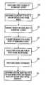
- FIG. 3is an illustration of the computer process for prescribing a modified second-order tetrahedral element for the finite element simulation
- FIG. 4is an illustration of a tetrahedral element divided into hexahedral elements for the finite element simulation
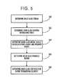
- FIG. 5is an illustration of the computer process for the hourglass control step
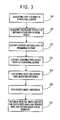
- FIG. 6is an illustration of the computer process for the stiffness integration step
- FIG. 7is an illustration of the computer process for the computing of the lumped mass matrix and distributed loads step
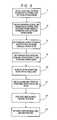
- FIG. 8is an illustration of the computer process for the implementation of the modified tetrahedral elements as an assembly of hexahedral sub-elements used in, for example, contact simulations or structural analysis;
- FIG. 9is an illustration of the computer process for the implementation of the determination and use of the external force vector and stiffness matrix of a hexahedral sub-element illustrated in FIG. 8;
- FIG. 10is an illustration of the computer process for the implementation of the determination and use of the hourglass force vector and hourglass stiffness matrix illustrated in FIG. 8;
- FIG. 11is an illustration of a main central processing unit for implementing the computer processing
- FIG. 12is a block diagram of the internal hardware of the computer illustrated in FIG. 11;
- FIG. 13is an illustration of an exemplary memory medium which can be used with disk drives illustrated in FIG. 11 or FIG. 12 .
- a procedureis here, and generally, conceived to be a self-consistent sequence of steps leading to a desired result. These steps are those requiring physical manipulations of physical quantities. Usually, though not necessarily, these quantities take the form of electrical or magnetic signals capable of being stored, transferred, combined, compared and otherwise manipulated. It proves convenient at times, principally for reasons of common usage, to refer to these signals as bits, values, elements, symbols, characters, terms, numbers, or the like. It should be noted, however, that all of these and similar terms are to be associated with the appropriate physical quantities and are merely convenient labels applied to these quantities.
- the manipulations performedare often referred to in terms, such as adding or comparing, which are commonly associated with mental operations performed by a human operator. No such capability of a human operator is necessary, or desirable in most cases, in any of the operations described herein which form part of the present invention; the operations are machine operations.
- Useful machines for performing the operation of the present inventioninclude general purpose digital computers or similar devices.
- the present inventionalso relates to apparatus for performing these operations.
- This apparatusmay be specially constructed for the required purpose or it may comprise a general purpose computer as selectively activated or reconfigured by a computer program stored in the computer.
- the procedures presented hereinare not inherently related to a particular computer or other apparatus.
- Various general purpose machinesmay be used with programs written in accordance with the teachings herein, or it may prove more convenient to construct more specialized apparatus to perform the required method steps. The required structure for a variety of these machines will appear from the description given.
- Second-order tetrahedral elementsusually give accurate results in small and finite deformation problems with no contact. However, we have determined that these elements are not appropriate for contact problems because in uniform pressure situations, the contact forces are non-uniform at the corner and midside nodes. We have further determined that equisized tetrahedra have zero contact forces at the corner nodes, so that the midside nodes carry all the contact load.
- Non-convergence of contact conditionsmay result especially with second-order tetrahedral elements.
- the second-order tetrahedral elementsmay also exhibit significant volumetric locking when incompressibility is approached.
- first-order tetrahedral elementsproduce uniform contact forces and pressures, but overall results can be very inaccurate due to severe volumetric and shear locking. In addition, very fine meshes may be needed to attain results of sufficient accuracy.
- FIG. 3is an illustration of the computer process for the formulation of modified second-order tetrahedral elements.
- the tetrahedral elementsare constructed in a composite manner; that is, they are composed of sub-elements that are hexahedral elements.
- the tetrahedral elementis composed of four uniform-strain hexahedra and fifteen nodes as illustrated in FIG. 4 .
- the first ten nodes(corner and mid-edge nodes) are defined by the user in Step S 18
- the last five nodesare defined and tracked by the computer process described herein.
- the mid-body node 11has independent degrees of freedom, and its displacement are determined as part of the solution of the overall equation system, described herein.
- the displacements of each of the mid-face nodes 12 to 15are dependent on the displacements of the corner and mid-edge nodes associated with the face.
- Each hexahedral sub-elementuses a uniform strain formulation, as originally developed by Flanagan and Belytschko, A Uniform Strain Hexahedron and Quadrilateral With Orthogonal Hourglass Control, International Journal for Numerical Methods in Engineering, vol. 17, pp.679-706 (1981), incorporated herein by reference.
- This formulationinsures that the rate of strain used in the formulation of the element is the true volume average of the rate of strain in the element.
- the Flanagan-Belytschko formulationhas been extended to obtain a consistent expression for the average deformation gradient that properly describes the volume change of the element.
- the basic equations of the uniform strain hexahedronare described in the Flanagan-Belytschko reference.
- Step S 20coefficients (e.g., A tri , B tri , A tet , B tet ) to result in uniform distribution of nodal forces are determined.
- the coefficients A tri , B trihave been determined analytically and numerically so that the equivalent nodal forces on the six external nodes of a face due to constant applied pressure on the face with a constrained mid-face node are uniform.
- the coefficients A tet , B tet for the mid-body nodehave been determined numerically so that the equivalent nodal forces on the ten external nodes of the element due to a constant applied body force on the element with constrained mid-body and mid-face nodes are approximately uniform.
- Step S 24The last four nodes of the tetrahedron (four midface nodes) are generated in Step S 24 by constraining their coordinates at all times using the following set of equations:
- x 12A tri ( x 1 +x 2 +x 3 )+ B tri ( x 5 +x 6 +x 7 )
- x 13A tri ( x 1 +x 2 +x 4 )+ B tri ( x 5 +x 8 +x 9 )
- x 14A tri ( x 2 +x 3 +x 4 )+ B tri ( x 6 +x 9 +x 10 )
- x 15A tri ( x 1 +x 3 +x 4 )+ B tri ( x 7 +x 8 +x 10 ) (2)
- the first eleven nodes of the tetrahedronare unconstrained, (e.g., 10 external nodes and one internal node) by the computer implemented process in Step S 26 ; and the remaining four midface nodes are constrained in Step S 28 .
- Step S 30the effective shape function for the user defined and midbody nodes as well as the uniform-strain spatial derivative are determined.
- effective shape functions for nodes 1 to 11are created with the linear constraints on the tetrahedral midface nodes.
- N Iare the standard trilinear shape functions of the first hexahedron.
- N I effare the effective shape functions.
- N I effare the effective shape functions.
- N 1 effN 1 +A tri ( N 12 +N 13 +N 15 ) (6)
- the effective strain displacement matrix B I eff for node Iis then constructed with the standard procedure using the uniform strain spatial derivatives of the effective shape functions, ⁇ overscore ( ⁇ NI eff ) ⁇ / ⁇ x.
- FIG. 5is an illustration of the computer process for the hourglass control step.
- Simple rigid body mode counts confirmed by eigenvalue analysis of single elementsindicate the presence of three hourglass modes for the tetrahedral elements.
- Hourglass stiffnessis added to these elements to suppress these modes.
- One alternativeis to use the standard hourglass stiffness formulation used for the reduced integration uniform-strain hexahedra described by Flanagan and Belytschko. However, this scheme can add significantly to the element computational expense.
- the parameter lprovides a length scale and is equal to the circumscribed circle or sphere radius r circum of the tetrahedron.
- a effis an effective area of the element through which the hourglass force acts and is equal to ⁇ r 2 inscr for a tetrahedron, where r inscr is the inscribed circle or sphere radius of the triangle or tetrahedron.
- C 0is the linear hourglass stiffness whose magnitude is of the order of Young's modulus or higher.
- the first term of the force F HGconstitutes the constant hourglass stiffness contribution and is analogous to linear springs in fixed X, Y, and Z directions.
- the second termprovides a nonlinear, rapidly increasing function of the hourglass strain ⁇ x HG , analogous to an axial, nonlinear spring.
- This hourglass control schemethus selectively stiffens elements which are undergoing appreciable distortion, based on the midbody nodal displacements away from a mean position.
- the hourglass forces on the external nodes and the mid-body nodecan be determined according to the following in Step S 64 :
- the element hourglass stiffnessis computed according to the following in Step S 68 :
- FIG. 6is an illustration of the computer process for the force and stiffness integration step.
- Step S 32the number of integration points are determined for the tetrahedron. Since each hexahedral sub-element (se) has only one integration point, the number of integration points is equal to the number of sub-elements; that is, four for the tetrahedron.
- D seare the material moduli in sub-element se and K ⁇ IJ is the initial stiffness matrix for the sub-element, constructed using the standard formulation for hexahedral elements (see ABAQUS Theory Manual at Section 3.2.2, incorporated by reference above), but using the uniform-strain spatial derivatives of the effective shape functions, ⁇ N I eff / ⁇ x.
- FIG. 7is an illustration of the computer process for the mass matrices formation step.
- a mass lumping schemeis used to provide uniform nodal masses for tetrahedral elements used in dynamic analysis.
- the mass matrixis constructed as follows.
- the nodal masses of the hexahedral sub-elementsare defined in Step S 52 by the following lumping scheme:
- Step S 54Distributed loads, including body and pressure loads, are computed in the standard manner using the effective interpolative functions in Step S 54 .
- Step S 56the pressure and body load stiffnesses are computed in the standard manner implemented by ABAQUS (see Sections 3.2.10 and 6.1.1, incorporated herein by reference).
- FIG. 8is an illustration of the computer process for the implementation of the modified tetrahedral elements used in, for example, contact simulations or structural analysis.
- the contribution to the external force vector and stiffness matrixis calculated in Step S 2 .
- the contribution to the external force vector and stiffness matrixis added into the tetrahedral force vector and stiffness matrix, respectively, in Step S 4 .
- the hourglass force vector and hourglass stiffness matrixare calculated in Step S 6 .
- the hourglass force vector and hourglass stiffness matrixare added into the force vector and stiffness matrix in Step S 8 .
- the lumped element mass matrixis generated for each sub-element in Step S 10 , and the lumped sub-element mass matrices are added into the lumped tetrahedral element mass matrix in Step S 12 .
- Step S 14If body loads or surface pressures are applied to the element in Step S 14 (optional), equivalent nodal loads and load stiffnesses are computed in the usual way in Step S 16 (optional). The above results are then used in determining structural integrity, including characteristics relating to displacement, natural frequency, stresses, stiffness and the like of the structure.
- FIG. 9is an illustration of the computer process for the implementation of the determination and use of the external force vector and stiffness matrix illustrated in FIG. 8 .
- the uniform strain gradient operator for the hexahedron ⁇ overscore ( ⁇ N I / ⁇ x) ⁇is calculated in Step S 38 .
- the effective uniform strain gradient operator ⁇ overscore ( ⁇ N I eff / ⁇ x) ⁇is obtained in Step S 40 .
- the effective strain displacement matrix B I effis constructed using the usual procedure in Step S 42 .
- Step S 44From the material behavior laws, the stress ⁇ SE and the material moduli D SE are calculated in Step S 44 . From the deformed shape of the sub-element, the current sub-element volume v se is calculated in the standard manner. With the above quantities, the force contribution B I eff ⁇ se v se and the stiffness contribution B I eff D se B J eff v se are determined in Step S 46 . With the effective uniform strain gradient operator, the initial stress stiffness matrix K IJ ⁇ is calculated in Step S 48 , and added to the sub-element stiffness matrix calculated above in Step S 50 .
- FIG. 10is an illustration of the computer process for the implementation of the determination and use of the hourglass force vector and hourglass stiffness matrix illustrated in FIG. 8 .
- the hourglass vector ⁇ Iis formed in Step S 70 .
- the hourglass strain ⁇ x HGis calculated with equation (9) in Step S 72 .
- the hourglass force F HGis calculated with equation (10) in Step S 74 .
- the hourglass modulus matrix D HGis calculated with equation (12).
- Step S 78the hourglass force vector P I HG and hourglass stiffness matrix K IJ HG are formed with equations (11) and (13).
- FIG. 11is an illustration of computer system 218 for implementing the computer processing in accordance with one embodiment of the present invention.
- computer system 218includes central processing unit 234 having disk drives 236 and 238 .
- Disk drive indications 236 and 238are merely symbolic of the number of disk drives which might be accommodated in this computer system. Typically, these would include a floppy disk drive such as 236 , a hard disk drive (not shown either internally or externally) and a CD ROM indicated by slot 238 .
- the number and type of drivesvaries, typically with different computer configurations.
- the computerincludes display 240 upon which information is displayed.
- a keyboard 242 and a mouse 244are typically also available as input devices via a standard interface.
- FIG. 12is a block diagram of the internal hardware of the computer 218 illustrated in FIG. 11 .
- data bus 248serves as the main information highway interconnecting the other components of the computer system.
- Central processing units (CPU) 250is the central processing unit of the system performing calculations and logic operations required to execute a program.
- Read-only memory 252 and random access memory 254constitute the main memory of the computer, and may be used to store the simulation data.
- Disk controller 256interfaces one or more disk drives to the system bus 248 .
- These disk drivesmay be floppy disk drives such as 262 , internal or external hard drives such as 260 , or CD ROM or DVD (digital video disks) drives such as 258 .
- a display interface 264interfaces with display 240 and permits information from the bus 248 to be displayed on the display 240 . Communications with the external devices can occur on communications port 266 .
- FIG. 13is an illustration of an exemplary memory medium which can be used with disk drives such as 262 in FIG. 12 or 236 in FIG. 11 .
- memory mediasuch as a floppy disk, or a CD ROM, or a digital video disk will contain, inter alia, the program information for controlling the computer to enable the computer to perform the testing and development functions in accordance with the computer system described herein.
Landscapes
- Engineering & Computer Science (AREA)
- Physics & Mathematics (AREA)
- Theoretical Computer Science (AREA)
- Computer Hardware Design (AREA)
- Evolutionary Computation (AREA)
- Geometry (AREA)
- General Engineering & Computer Science (AREA)
- General Physics & Mathematics (AREA)
- Management, Administration, Business Operations System, And Electronic Commerce (AREA)
Abstract
Description


Claims (23)
Priority Applications (1)
| Application Number | Priority Date | Filing Date | Title |
|---|---|---|---|
| US09/500,973US6697770B1 (en) | 1997-06-05 | 2000-02-15 | Computer process for prescribing second-order tetrahedral elements during deformation simulation in the design analysis of structures |
Applications Claiming Priority (2)
| Application Number | Priority Date | Filing Date | Title |
|---|---|---|---|
| US08/870,236US6044210A (en) | 1997-06-05 | 1997-06-05 | Computer process for prescribing second-order tetrahedral elements during deformation simulation in the design analysis of structures |
| US09/500,973US6697770B1 (en) | 1997-06-05 | 2000-02-15 | Computer process for prescribing second-order tetrahedral elements during deformation simulation in the design analysis of structures |
Related Parent Applications (1)
| Application Number | Title | Priority Date | Filing Date |
|---|---|---|---|
| US08/870,236Continuation-In-PartUS6044210A (en) | 1997-06-05 | 1997-06-05 | Computer process for prescribing second-order tetrahedral elements during deformation simulation in the design analysis of structures |
Publications (1)
| Publication Number | Publication Date |
|---|---|
| US6697770B1true US6697770B1 (en) | 2004-02-24 |
Family
ID=25355007
Family Applications (2)
| Application Number | Title | Priority Date | Filing Date |
|---|---|---|---|
| US08/870,236Expired - LifetimeUS6044210A (en) | 1997-06-05 | 1997-06-05 | Computer process for prescribing second-order tetrahedral elements during deformation simulation in the design analysis of structures |
| US09/500,973Expired - LifetimeUS6697770B1 (en) | 1997-06-05 | 2000-02-15 | Computer process for prescribing second-order tetrahedral elements during deformation simulation in the design analysis of structures |
Family Applications Before (1)
| Application Number | Title | Priority Date | Filing Date |
|---|---|---|---|
| US08/870,236Expired - LifetimeUS6044210A (en) | 1997-06-05 | 1997-06-05 | Computer process for prescribing second-order tetrahedral elements during deformation simulation in the design analysis of structures |
Country Status (1)
| Country | Link |
|---|---|
| US (2) | US6044210A (en) |
Cited By (45)
| Publication number | Priority date | Publication date | Assignee | Title |
|---|---|---|---|---|
| US20030046046A1 (en)* | 2001-08-30 | 2003-03-06 | International Business Machines Corporation | Tetrahedralization of non-conformal three-dimensional mixed element meshes |
| US20050107963A1 (en)* | 2002-03-02 | 2005-05-19 | Robert Campbell | Method for assessing the integrity of a structure |
| US20070282571A1 (en)* | 2006-05-30 | 2007-12-06 | The Boeing Company | Finite element modeling method utilizing mass distribution |
| US7392163B1 (en)* | 2004-03-25 | 2008-06-24 | Livermore Software Technology Corporation | Method and system for controlling hourglass deformations of solid elements in finite element analysis |
| US20080195357A1 (en)* | 2006-09-14 | 2008-08-14 | Peter Allen Gustafson | Method and system for determining field quantities in a structural joint |
| US20100004911A1 (en)* | 2007-03-16 | 2010-01-07 | Bayerische Motoren Werke Aktiengesellschaft | Method for Simulating a Physical Property of a Technical Structure by a Component Model |
| US20110114615A1 (en)* | 2009-11-13 | 2011-05-19 | Lincoln Global, Inc. | Systems, methods, and apparatuses for monitoring weld quality |
| US20110183304A1 (en)* | 2009-07-10 | 2011-07-28 | Lincoln Global, Inc. | Virtual testing and inspection of a virtual weldment |
| US20110191072A1 (en)* | 2010-02-02 | 2011-08-04 | Livermore Software Technology Corporation | Fully-integrated hexahedral elements configured for reducing shear locking in finite element method |
| US20120023735A1 (en)* | 2009-04-23 | 2012-02-02 | Iag Magnum Gmbh | Method for the production of extra heavy pipe joints, preferably for off-shore wind energy plants |
| US8747116B2 (en) | 2008-08-21 | 2014-06-10 | Lincoln Global, Inc. | System and method providing arc welding training in a real-time simulated virtual reality environment using real-time weld puddle feedback |
| US8834168B2 (en) | 2008-08-21 | 2014-09-16 | Lincoln Global, Inc. | System and method providing combined virtual reality arc welding and three-dimensional (3D) viewing |
| US8851896B2 (en) | 2008-08-21 | 2014-10-07 | Lincoln Global, Inc. | Virtual reality GTAW and pipe welding simulator and setup |
| US8884177B2 (en) | 2009-11-13 | 2014-11-11 | Lincoln Global, Inc. | Systems, methods, and apparatuses for monitoring weld quality |
| US8911237B2 (en) | 2008-08-21 | 2014-12-16 | Lincoln Global, Inc. | Virtual reality pipe welding simulator and setup |
| USRE45398E1 (en) | 2009-03-09 | 2015-03-03 | Lincoln Global, Inc. | System for tracking and analyzing welding activity |
| US9011154B2 (en) | 2009-07-10 | 2015-04-21 | Lincoln Global, Inc. | Virtual welding system |
| US9196169B2 (en) | 2008-08-21 | 2015-11-24 | Lincoln Global, Inc. | Importing and analyzing external data using a virtual reality welding system |
| US9221117B2 (en) | 2009-07-08 | 2015-12-29 | Lincoln Global, Inc. | System for characterizing manual welding operations |
| US9230449B2 (en) | 2009-07-08 | 2016-01-05 | Lincoln Global, Inc. | Welding training system |
| US9318026B2 (en) | 2008-08-21 | 2016-04-19 | Lincoln Global, Inc. | Systems and methods providing an enhanced user experience in a real-time simulated virtual reality welding environment |
| US9330575B2 (en) | 2008-08-21 | 2016-05-03 | Lincoln Global, Inc. | Tablet-based welding simulator |
| US9468988B2 (en) | 2009-11-13 | 2016-10-18 | Lincoln Global, Inc. | Systems, methods, and apparatuses for monitoring weld quality |
| US9483959B2 (en) | 2008-08-21 | 2016-11-01 | Lincoln Global, Inc. | Welding simulator |
| US20160364512A1 (en)* | 2015-06-09 | 2016-12-15 | The Boeing Company | Modeling holes and fasteners for finite element analysis |
| US9685099B2 (en) | 2009-07-08 | 2017-06-20 | Lincoln Global, Inc. | System for characterizing manual welding operations |
| US9767712B2 (en) | 2012-07-10 | 2017-09-19 | Lincoln Global, Inc. | Virtual reality pipe welding simulator and setup |
| US9773429B2 (en) | 2009-07-08 | 2017-09-26 | Lincoln Global, Inc. | System and method for manual welder training |
| US9836987B2 (en) | 2014-02-14 | 2017-12-05 | Lincoln Global, Inc. | Virtual reality pipe welding simulator and setup |
| US9895267B2 (en) | 2009-10-13 | 2018-02-20 | Lincoln Global, Inc. | Welding helmet with integral user interface |
| US9911359B2 (en) | 2009-07-10 | 2018-03-06 | Lincoln Global, Inc. | Virtual testing and inspection of a virtual weldment |
| US10083627B2 (en) | 2013-11-05 | 2018-09-25 | Lincoln Global, Inc. | Virtual reality and real welding training system and method |
| US10198962B2 (en) | 2013-09-11 | 2019-02-05 | Lincoln Global, Inc. | Learning management system for a real-time simulated virtual reality welding training environment |
| US10473447B2 (en) | 2016-11-04 | 2019-11-12 | Lincoln Global, Inc. | Magnetic frequency selection for electromagnetic position tracking |
| US10475353B2 (en) | 2014-09-26 | 2019-11-12 | Lincoln Global, Inc. | System for characterizing manual welding operations on pipe and other curved structures |
| US10496080B2 (en) | 2006-12-20 | 2019-12-03 | Lincoln Global, Inc. | Welding job sequencer |
| US10748447B2 (en) | 2013-05-24 | 2020-08-18 | Lincoln Global, Inc. | Systems and methods providing a computerized eyewear device to aid in welding |
| US10878591B2 (en) | 2016-11-07 | 2020-12-29 | Lincoln Global, Inc. | Welding trainer utilizing a head up display to display simulated and real-world objects |
| US10913125B2 (en) | 2016-11-07 | 2021-02-09 | Lincoln Global, Inc. | Welding system providing visual and audio cues to a welding helmet with a display |
| US10930174B2 (en) | 2013-05-24 | 2021-02-23 | Lincoln Global, Inc. | Systems and methods providing a computerized eyewear device to aid in welding |
| US10940555B2 (en) | 2006-12-20 | 2021-03-09 | Lincoln Global, Inc. | System for a welding sequencer |
| US10997872B2 (en) | 2017-06-01 | 2021-05-04 | Lincoln Global, Inc. | Spring-loaded tip assembly to support simulated shielded metal arc welding |
| US10994358B2 (en) | 2006-12-20 | 2021-05-04 | Lincoln Global, Inc. | System and method for creating or modifying a welding sequence based on non-real world weld data |
| US11475792B2 (en) | 2018-04-19 | 2022-10-18 | Lincoln Global, Inc. | Welding simulator with dual-user configuration |
| US11557223B2 (en) | 2018-04-19 | 2023-01-17 | Lincoln Global, Inc. | Modular and reconfigurable chassis for simulated welding training |
Families Citing this family (17)
| Publication number | Priority date | Publication date | Assignee | Title |
|---|---|---|---|---|
| US6044210A (en)* | 1997-06-05 | 2000-03-28 | Hibbitt Karlsson & Sorensen, Inc. | Computer process for prescribing second-order tetrahedral elements during deformation simulation in the design analysis of structures |
| TW445334B (en) | 1999-06-01 | 2001-07-11 | Ohbayashi Corp | Elevated bridge infrastructure and design method for designing the same |
| ATE498868T1 (en)* | 1999-10-15 | 2011-03-15 | Moldflow Pty Ltd | SYSTEM AND METHOD FOR STRUCTURAL ANALYSIS |
| BR0107614A (en)* | 2000-01-12 | 2004-01-13 | Karma2Go Com Llc | Computer-implemented process for analyzing a structure |
| US6640149B1 (en)* | 2000-03-21 | 2003-10-28 | Alcan International Limited | System and method of developing a can bottom profile and a can with a domed bottom structure |
| AU2002345824A1 (en)* | 2001-06-22 | 2003-01-08 | Troy Marusich | Composite tetrahedral modeling element |
| US7606690B2 (en)* | 2001-12-18 | 2009-10-20 | Nhk International Corporation | Method and apparatus for modeling coil springs using a force field generator |
| US7027048B2 (en)* | 2002-05-31 | 2006-04-11 | Ugs Corp. | Computerized deformation analyzer |
| US7110926B2 (en)* | 2003-10-29 | 2006-09-19 | Nhk International Corp. | Universal spring mechanism for automobile suspension system design |
| DE102007012634A1 (en)* | 2007-03-16 | 2008-09-18 | Bayerische Motoren Werke Aktiengesellschaft | Automatically creating a mesh of a component model |
| US8494819B2 (en)* | 2010-08-25 | 2013-07-23 | Livermore Software Technology Corp. | Efficient data management for shell finite elements representing layered composite materials |
| US8612186B2 (en)* | 2011-03-01 | 2013-12-17 | Livermore Software Technology Corp. | Numerical simulation of structural behaviors using a meshfree-enriched finite element method |
| JP5227436B2 (en)* | 2011-03-18 | 2013-07-03 | 住友ゴム工業株式会社 | How to create a finite element model of filler compounded rubber |
| EP2757429A1 (en)* | 2013-01-17 | 2014-07-23 | BAE Systems PLC | Object production |
| GB2511914B (en) | 2013-01-17 | 2015-09-23 | Bae Systems Plc | Object production |
| JP5585671B2 (en)* | 2013-02-01 | 2014-09-10 | Jfeスチール株式会社 | Shape optimization analysis method and apparatus |
| US10042962B2 (en)* | 2014-05-20 | 2018-08-07 | The Boeing Company | Mid-surface extraction for finite element analysis |
Citations (9)
| Publication number | Priority date | Publication date | Assignee | Title |
|---|---|---|---|---|
| US5010501A (en)* | 1987-10-20 | 1991-04-23 | Matsushita Electric Industrial Co., Ltd. | Three-dimensional geometry processing method and apparatus therefor |
| US5136497A (en)* | 1990-07-12 | 1992-08-04 | Bdm International, Inc. | Material consolidation modeling and control system |
| US5222202A (en)* | 1989-10-13 | 1993-06-22 | International Business Machines Corporation | Method and apparatus for visualization of iso-valued surfaces |
| US5345490A (en)* | 1991-06-28 | 1994-09-06 | General Electric Company | Method and apparatus for converting computed tomography (CT) data into finite element models |
| US5442569A (en)* | 1993-06-23 | 1995-08-15 | Oceanautes Inc. | Method and apparatus for system characterization and analysis using finite element methods |
| US5729462A (en)* | 1995-08-25 | 1998-03-17 | Northrop Grumman Corporation | Method and apparatus for constructing a complex tool surface for use in an age forming process |
| US5936869A (en)* | 1995-05-25 | 1999-08-10 | Matsushita Electric Industrial Co., Ltd. | Method and device for generating mesh for use in numerical analysis |
| US6044210A (en)* | 1997-06-05 | 2000-03-28 | Hibbitt Karlsson & Sorensen, Inc. | Computer process for prescribing second-order tetrahedral elements during deformation simulation in the design analysis of structures |
| US6132108A (en)* | 1997-01-23 | 2000-10-17 | Nhk Spring Co., Ltd. | Design support method for a structure and the like |
- 1997
- 1997-06-05USUS08/870,236patent/US6044210A/ennot_activeExpired - Lifetime
- 2000
- 2000-02-15USUS09/500,973patent/US6697770B1/ennot_activeExpired - Lifetime
Patent Citations (9)
| Publication number | Priority date | Publication date | Assignee | Title |
|---|---|---|---|---|
| US5010501A (en)* | 1987-10-20 | 1991-04-23 | Matsushita Electric Industrial Co., Ltd. | Three-dimensional geometry processing method and apparatus therefor |
| US5222202A (en)* | 1989-10-13 | 1993-06-22 | International Business Machines Corporation | Method and apparatus for visualization of iso-valued surfaces |
| US5136497A (en)* | 1990-07-12 | 1992-08-04 | Bdm International, Inc. | Material consolidation modeling and control system |
| US5345490A (en)* | 1991-06-28 | 1994-09-06 | General Electric Company | Method and apparatus for converting computed tomography (CT) data into finite element models |
| US5442569A (en)* | 1993-06-23 | 1995-08-15 | Oceanautes Inc. | Method and apparatus for system characterization and analysis using finite element methods |
| US5936869A (en)* | 1995-05-25 | 1999-08-10 | Matsushita Electric Industrial Co., Ltd. | Method and device for generating mesh for use in numerical analysis |
| US5729462A (en)* | 1995-08-25 | 1998-03-17 | Northrop Grumman Corporation | Method and apparatus for constructing a complex tool surface for use in an age forming process |
| US6132108A (en)* | 1997-01-23 | 2000-10-17 | Nhk Spring Co., Ltd. | Design support method for a structure and the like |
| US6044210A (en)* | 1997-06-05 | 2000-03-28 | Hibbitt Karlsson & Sorensen, Inc. | Computer process for prescribing second-order tetrahedral elements during deformation simulation in the design analysis of structures |
Cited By (97)
| Publication number | Priority date | Publication date | Assignee | Title |
|---|---|---|---|---|
| US20060071931A1 (en)* | 2001-08-30 | 2006-04-06 | International Business Machines Corporation | Tetrahedralization of non-conformal three-dimensional mixed element meshes |
| US7099805B2 (en)* | 2001-08-30 | 2006-08-29 | International Business Machines Corporation | Tetrahedralization of non-conformal three-dimensional mixed element meshes |
| US20030046046A1 (en)* | 2001-08-30 | 2003-03-06 | International Business Machines Corporation | Tetrahedralization of non-conformal three-dimensional mixed element meshes |
| US7698112B2 (en)* | 2001-08-30 | 2010-04-13 | International Business Machines Corporation | Tetrahedralization of non-conformal three-dimensional mixed element meshes |
| US20050107963A1 (en)* | 2002-03-02 | 2005-05-19 | Robert Campbell | Method for assessing the integrity of a structure |
| US7546224B2 (en)* | 2002-03-02 | 2009-06-09 | Robert Campbell | Method for assessing the integrity of a structure |
| US7392163B1 (en)* | 2004-03-25 | 2008-06-24 | Livermore Software Technology Corporation | Method and system for controlling hourglass deformations of solid elements in finite element analysis |
| US7840386B2 (en)* | 2006-05-30 | 2010-11-23 | The Boeing Company | Finite element modeling method utilizing mass distribution |
| US20070282571A1 (en)* | 2006-05-30 | 2007-12-06 | The Boeing Company | Finite element modeling method utilizing mass distribution |
| US20080195357A1 (en)* | 2006-09-14 | 2008-08-14 | Peter Allen Gustafson | Method and system for determining field quantities in a structural joint |
| US11980976B2 (en) | 2006-12-20 | 2024-05-14 | Lincoln Global, Inc. | Method for a welding sequencer |
| US10496080B2 (en) | 2006-12-20 | 2019-12-03 | Lincoln Global, Inc. | Welding job sequencer |
| US10940555B2 (en) | 2006-12-20 | 2021-03-09 | Lincoln Global, Inc. | System for a welding sequencer |
| US10994358B2 (en) | 2006-12-20 | 2021-05-04 | Lincoln Global, Inc. | System and method for creating or modifying a welding sequence based on non-real world weld data |
| US8473266B2 (en)* | 2007-03-16 | 2013-06-25 | Bayerische Motoren Werke Aktiengesellschaft | Method for simulating a physical property of a technical structure by a component model |
| US20100004911A1 (en)* | 2007-03-16 | 2010-01-07 | Bayerische Motoren Werke Aktiengesellschaft | Method for Simulating a Physical Property of a Technical Structure by a Component Model |
| US10803770B2 (en) | 2008-08-21 | 2020-10-13 | Lincoln Global, Inc. | Importing and analyzing external data using a virtual reality welding system |
| US9196169B2 (en) | 2008-08-21 | 2015-11-24 | Lincoln Global, Inc. | Importing and analyzing external data using a virtual reality welding system |
| US11521513B2 (en) | 2008-08-21 | 2022-12-06 | Lincoln Global, Inc. | Importing and analyzing external data using a virtual reality welding system |
| US8747116B2 (en) | 2008-08-21 | 2014-06-10 | Lincoln Global, Inc. | System and method providing arc welding training in a real-time simulated virtual reality environment using real-time weld puddle feedback |
| US8834168B2 (en) | 2008-08-21 | 2014-09-16 | Lincoln Global, Inc. | System and method providing combined virtual reality arc welding and three-dimensional (3D) viewing |
| US8851896B2 (en) | 2008-08-21 | 2014-10-07 | Lincoln Global, Inc. | Virtual reality GTAW and pipe welding simulator and setup |
| US10916153B2 (en) | 2008-08-21 | 2021-02-09 | Lincoln Global, Inc. | Systems and methods providing an enhanced user experience in a real-time simulated virtual reality welding environment |
| US8911237B2 (en) | 2008-08-21 | 2014-12-16 | Lincoln Global, Inc. | Virtual reality pipe welding simulator and setup |
| US9779635B2 (en) | 2008-08-21 | 2017-10-03 | Lincoln Global, Inc. | Importing and analyzing external data using a virtual reality welding system |
| US10762802B2 (en) | 2008-08-21 | 2020-09-01 | Lincoln Global, Inc. | Welding simulator |
| US10629093B2 (en) | 2008-08-21 | 2020-04-21 | Lincoln Global Inc. | Systems and methods providing enhanced education and training in a virtual reality environment |
| US11715388B2 (en) | 2008-08-21 | 2023-08-01 | Lincoln Global, Inc. | Importing and analyzing external data using a virtual reality welding system |
| US12136353B2 (en) | 2008-08-21 | 2024-11-05 | Lincoln Global, Inc. | Importing and analyzing external data using a virtual reality welding system |
| US10249215B2 (en) | 2008-08-21 | 2019-04-02 | Lincoln Global, Inc. | Systems and methods providing enhanced education and training in a virtual reality environment |
| US10056011B2 (en) | 2008-08-21 | 2018-08-21 | Lincoln Global, Inc. | Importing and analyzing external data using a virtual reality welding system |
| US11030920B2 (en) | 2008-08-21 | 2021-06-08 | Lincoln Global, Inc. | Importing and analyzing external data using a virtual reality welding system |
| US9965973B2 (en) | 2008-08-21 | 2018-05-08 | Lincoln Global, Inc. | Systems and methods providing enhanced education and training in a virtual reality environment |
| US9928755B2 (en) | 2008-08-21 | 2018-03-27 | Lincoln Global, Inc. | Virtual reality GTAW and pipe welding simulator and setup |
| US9858833B2 (en) | 2008-08-21 | 2018-01-02 | Lincoln Global, Inc. | Importing and analyzing external data using a virtual reality welding system |
| US9293057B2 (en) | 2008-08-21 | 2016-03-22 | Lincoln Global, Inc. | Importing and analyzing external data using a virtual reality welding system |
| US9293056B2 (en) | 2008-08-21 | 2016-03-22 | Lincoln Global, Inc. | Importing and analyzing external data using a virtual reality welding system |
| US9318026B2 (en) | 2008-08-21 | 2016-04-19 | Lincoln Global, Inc. | Systems and methods providing an enhanced user experience in a real-time simulated virtual reality welding environment |
| US9330575B2 (en) | 2008-08-21 | 2016-05-03 | Lincoln Global, Inc. | Tablet-based welding simulator |
| US9336686B2 (en) | 2008-08-21 | 2016-05-10 | Lincoln Global, Inc. | Tablet-based welding simulator |
| US9836995B2 (en) | 2008-08-21 | 2017-12-05 | Lincoln Global, Inc. | Importing and analyzing external data using a virtual reality welding system |
| US9483959B2 (en) | 2008-08-21 | 2016-11-01 | Lincoln Global, Inc. | Welding simulator |
| US9818311B2 (en) | 2008-08-21 | 2017-11-14 | Lincoln Global, Inc. | Importing and analyzing external data using a virtual reality welding system |
| US9818312B2 (en) | 2008-08-21 | 2017-11-14 | Lincoln Global, Inc. | Importing and analyzing external data using a virtual reality welding system |
| US9691299B2 (en) | 2008-08-21 | 2017-06-27 | Lincoln Global, Inc. | Systems and methods providing an enhanced user experience in a real-time simulated virtual reality welding environment |
| US9754509B2 (en) | 2008-08-21 | 2017-09-05 | Lincoln Global, Inc. | Importing and analyzing external data using a virtual reality welding system |
| US9761153B2 (en) | 2008-08-21 | 2017-09-12 | Lincoln Global, Inc. | Importing and analyzing external data using a virtual reality welding system |
| US9779636B2 (en) | 2008-08-21 | 2017-10-03 | Lincoln Global, Inc. | Importing and analyzing external data using a virtual reality welding system |
| USRE47918E1 (en) | 2009-03-09 | 2020-03-31 | Lincoln Global, Inc. | System for tracking and analyzing welding activity |
| USRE45398E1 (en) | 2009-03-09 | 2015-03-03 | Lincoln Global, Inc. | System for tracking and analyzing welding activity |
| US20120023735A1 (en)* | 2009-04-23 | 2012-02-02 | Iag Magnum Gmbh | Method for the production of extra heavy pipe joints, preferably for off-shore wind energy plants |
| US9230449B2 (en) | 2009-07-08 | 2016-01-05 | Lincoln Global, Inc. | Welding training system |
| US9685099B2 (en) | 2009-07-08 | 2017-06-20 | Lincoln Global, Inc. | System for characterizing manual welding operations |
| US9773429B2 (en) | 2009-07-08 | 2017-09-26 | Lincoln Global, Inc. | System and method for manual welder training |
| US10522055B2 (en) | 2009-07-08 | 2019-12-31 | Lincoln Global, Inc. | System for characterizing manual welding operations |
| US10347154B2 (en) | 2009-07-08 | 2019-07-09 | Lincoln Global, Inc. | System for characterizing manual welding operations |
| US10068495B2 (en) | 2009-07-08 | 2018-09-04 | Lincoln Global, Inc. | System for characterizing manual welding operations |
| US9221117B2 (en) | 2009-07-08 | 2015-12-29 | Lincoln Global, Inc. | System for characterizing manual welding operations |
| US8657605B2 (en) | 2009-07-10 | 2014-02-25 | Lincoln Global, Inc. | Virtual testing and inspection of a virtual weldment |
| US9911360B2 (en) | 2009-07-10 | 2018-03-06 | Lincoln Global, Inc. | Virtual testing and inspection of a virtual weldment |
| US9911359B2 (en) | 2009-07-10 | 2018-03-06 | Lincoln Global, Inc. | Virtual testing and inspection of a virtual weldment |
| US20110183304A1 (en)* | 2009-07-10 | 2011-07-28 | Lincoln Global, Inc. | Virtual testing and inspection of a virtual weldment |
| US10991267B2 (en) | 2009-07-10 | 2021-04-27 | Lincoln Global, Inc. | Systems and methods providing a computerized eyewear device to aid in welding |
| US10643496B2 (en) | 2009-07-10 | 2020-05-05 | Lincoln Global Inc. | Virtual testing and inspection of a virtual weldment |
| US10134303B2 (en) | 2009-07-10 | 2018-11-20 | Lincoln Global, Inc. | Systems and methods providing enhanced education and training in a virtual reality environment |
| US9011154B2 (en) | 2009-07-10 | 2015-04-21 | Lincoln Global, Inc. | Virtual welding system |
| US9836994B2 (en) | 2009-07-10 | 2017-12-05 | Lincoln Global, Inc. | Virtual welding system |
| US9895267B2 (en) | 2009-10-13 | 2018-02-20 | Lincoln Global, Inc. | Welding helmet with integral user interface |
| US9468988B2 (en) | 2009-11-13 | 2016-10-18 | Lincoln Global, Inc. | Systems, methods, and apparatuses for monitoring weld quality |
| US8569646B2 (en) | 2009-11-13 | 2013-10-29 | Lincoln Global, Inc. | Systems, methods, and apparatuses for monitoring weld quality |
| US20110114615A1 (en)* | 2009-11-13 | 2011-05-19 | Lincoln Global, Inc. | Systems, methods, and apparatuses for monitoring weld quality |
| US9050678B2 (en) | 2009-11-13 | 2015-06-09 | Lincoln Global, Inc. | Systems, methods, and apparatuses for monitoring weld quality |
| US9050679B2 (en) | 2009-11-13 | 2015-06-09 | Lincoln Global, Inc. | Systems, methods, and apparatuses for monitoring weld quality |
| US9012802B2 (en) | 2009-11-13 | 2015-04-21 | Lincoln Global, Inc. | Systems, methods, and apparatuses for monitoring weld quality |
| US9089921B2 (en) | 2009-11-13 | 2015-07-28 | Lincoln Global, Inc. | Systems, methods, and apparatuses for monitoring weld quality |
| US8884177B2 (en) | 2009-11-13 | 2014-11-11 | Lincoln Global, Inc. | Systems, methods, and apparatuses for monitoring weld quality |
| US8987628B2 (en) | 2009-11-13 | 2015-03-24 | Lincoln Global, Inc. | Systems, methods, and apparatuses for monitoring weld quality |
| US20110191072A1 (en)* | 2010-02-02 | 2011-08-04 | Livermore Software Technology Corporation | Fully-integrated hexahedral elements configured for reducing shear locking in finite element method |
| US8271237B2 (en)* | 2010-02-02 | 2012-09-18 | Livermore Software Technology Corporation | Fully-integrated hexahedral elements configured for reducing shear locking in finite element method |
| US9269279B2 (en) | 2010-12-13 | 2016-02-23 | Lincoln Global, Inc. | Welding training system |
| US9767712B2 (en) | 2012-07-10 | 2017-09-19 | Lincoln Global, Inc. | Virtual reality pipe welding simulator and setup |
| US10748447B2 (en) | 2013-05-24 | 2020-08-18 | Lincoln Global, Inc. | Systems and methods providing a computerized eyewear device to aid in welding |
| US10930174B2 (en) | 2013-05-24 | 2021-02-23 | Lincoln Global, Inc. | Systems and methods providing a computerized eyewear device to aid in welding |
| US10198962B2 (en) | 2013-09-11 | 2019-02-05 | Lincoln Global, Inc. | Learning management system for a real-time simulated virtual reality welding training environment |
| US11100812B2 (en) | 2013-11-05 | 2021-08-24 | Lincoln Global, Inc. | Virtual reality and real welding training system and method |
| US10083627B2 (en) | 2013-11-05 | 2018-09-25 | Lincoln Global, Inc. | Virtual reality and real welding training system and method |
| US9836987B2 (en) | 2014-02-14 | 2017-12-05 | Lincoln Global, Inc. | Virtual reality pipe welding simulator and setup |
| US10720074B2 (en) | 2014-02-14 | 2020-07-21 | Lincoln Global, Inc. | Welding simulator |
| US10475353B2 (en) | 2014-09-26 | 2019-11-12 | Lincoln Global, Inc. | System for characterizing manual welding operations on pipe and other curved structures |
| US20160364512A1 (en)* | 2015-06-09 | 2016-12-15 | The Boeing Company | Modeling holes and fasteners for finite element analysis |
| US10621293B2 (en)* | 2015-06-09 | 2020-04-14 | The Boeing Company | Modeling holes and fasteners for finite element analysis |
| US10473447B2 (en) | 2016-11-04 | 2019-11-12 | Lincoln Global, Inc. | Magnetic frequency selection for electromagnetic position tracking |
| US10913125B2 (en) | 2016-11-07 | 2021-02-09 | Lincoln Global, Inc. | Welding system providing visual and audio cues to a welding helmet with a display |
| US10878591B2 (en) | 2016-11-07 | 2020-12-29 | Lincoln Global, Inc. | Welding trainer utilizing a head up display to display simulated and real-world objects |
| US10997872B2 (en) | 2017-06-01 | 2021-05-04 | Lincoln Global, Inc. | Spring-loaded tip assembly to support simulated shielded metal arc welding |
| US11475792B2 (en) | 2018-04-19 | 2022-10-18 | Lincoln Global, Inc. | Welding simulator with dual-user configuration |
| US11557223B2 (en) | 2018-04-19 | 2023-01-17 | Lincoln Global, Inc. | Modular and reconfigurable chassis for simulated welding training |
Also Published As
| Publication number | Publication date |
|---|---|
| US6044210A (en) | 2000-03-28 |
Similar Documents
| Publication | Publication Date | Title |
|---|---|---|
| US6697770B1 (en) | Computer process for prescribing second-order tetrahedral elements during deformation simulation in the design analysis of structures | |
| KR100974992B1 (en) | Computer strain analyzer | |
| US10311180B2 (en) | System and method of recovering Lagrange multipliers in modal dynamic analysis | |
| US6813749B2 (en) | Method, system and computer program product for multidisciplinary design analysis of structural components | |
| Sawada et al. | LLM and X-FEM based interface modeling of fluid–thin structure interactions on a non-interface-fitted mesh | |
| US20180189433A1 (en) | Analytical Consistent Sensitivities For Nonlinear Equilibriums, Where The Only Source Of Nonlinearities Is Small Sliding Contact Constraints | |
| Peterlik et al. | Real-time visio-haptic interaction with static soft tissue models having geometric and material nonlinearity | |
| Taylor | FEAP-ein finite element analysis programm | |
| Shang et al. | Couple stress-based unsymmetric 8-node planar membrane elements with good tolerances to mesh distortion | |
| JP2024155903A (en) | Systems and methods for resolving numerical instabilities - Patents.com | |
| Toogood et al. | Pro/MECHANICA tutorial structure | |
| Teodoru | EBBEF2p-A Computer Code for Analysing Beams on Elastic Foundations | |
| Ma et al. | A 3D implicit structured multi-block grid finite volume method for computational structural dynamics | |
| Dodds Jr | NUMERICAL AND SOFTWARE REQUIREMENTS FOR GENERAL NONLINEAR FINITE-ELEMENT ANALYSIS. | |
| Benney et al. | A 3-D finite element structural parachute model | |
| Arruda | Static and dynamic analysis of concrete structures using damage mechanics | |
| Bergel et al. | Sierra/SolidMechanics 5.10 In-Development Manual | |
| Eriksson et al. | Discretization of Structural Models | |
| JP2004046379A (en) | Non-nodal point finite element method | |
| Campos et al. | A phenomenological discrete model for cardiac tissue mechanics | |
| Faas et al. | Interactive mesh-free stress analysis for mechanical design assembly with haptics | |
| Eriksson et al. | A Wider View | |
| Rückwald | Adaptive isogeometric impact models in flexible multibody systems | |
| Taylor | FEAPpv--A Finite Element Analysis Program | |
| WO2021205967A1 (en) | Hierarchical reduced-order matrix generation device |
Legal Events
| Date | Code | Title | Description |
|---|---|---|---|
| AS | Assignment | Owner name:HIBBIT, KARLSSON & SORENSEN, INC., RHODE ISLAND Free format text:ASSIGNMENT OF ASSIGNORS INTEREST;ASSIGNOR:NAGTEGAAL, JOOP C.;REEL/FRAME:010963/0534 Effective date:20000719 | |
| AS | Assignment | Owner name:ABAQUS, INC., RHODE ISLAND Free format text:CHANGE OF NAME;ASSIGNOR:HIBBITT, KARLSSON & SORENSEN, INC.;REEL/FRAME:014912/0529 Effective date:20021218 | |
| STCF | Information on status: patent grant | Free format text:PATENTED CASE | |
| FPAY | Fee payment | Year of fee payment:4 | |
| FEPP | Fee payment procedure | Free format text:PAYOR NUMBER ASSIGNED (ORIGINAL EVENT CODE: ASPN); ENTITY STATUS OF PATENT OWNER: LARGE ENTITY | |
| AS | Assignment | Owner name:ABAQUS, INC. (A WHOLLY OWNED SUBSIDIARY OF DASSAUL Free format text:MERGER;ASSIGNOR:AQUA ACQUISITION CORP.;REEL/FRAME:021924/0436 Effective date:20051003 | |
| AS | Assignment | Owner name:DASSAULT SYSTEMES SIMULIA CORP., RHODE ISLAND Free format text:CHANGE OF NAME;ASSIGNOR:ABAQUS, INC.;REEL/FRAME:021936/0377 Effective date:20070515 | |
| FEPP | Fee payment procedure | Free format text:PAT HOLDER NO LONGER CLAIMS SMALL ENTITY STATUS, ENTITY STATUS SET TO UNDISCOUNTED (ORIGINAL EVENT CODE: STOL); ENTITY STATUS OF PATENT OWNER: LARGE ENTITY | |
| REFU | Refund | Free format text:REFUND - PAYMENT OF MAINTENANCE FEE, 8TH YR, SMALL ENTITY (ORIGINAL EVENT CODE: R2552); ENTITY STATUS OF PATENT OWNER: LARGE ENTITY | |
| FPAY | Fee payment | Year of fee payment:8 | |
| FPAY | Fee payment | Year of fee payment:12 | |
| AS | Assignment | Owner name:DASSAULT SYSTEMES AMERICAS CORP., MASSACHUSETTS Free format text:MERGER;ASSIGNOR:DASSAULT SYSTEMES SIMULIA CORP.;REEL/FRAME:066383/0536 Effective date:20240101 |