US6697761B2 - Three-dimensional position/orientation sensing apparatus, information presenting system, and model error detecting system - Google Patents
Three-dimensional position/orientation sensing apparatus, information presenting system, and model error detecting systemDownload PDFInfo
- Publication number
- US6697761B2 US6697761B2US09/951,873US95187301AUS6697761B2US 6697761 B2US6697761 B2US 6697761B2US 95187301 AUS95187301 AUS 95187301AUS 6697761 B2US6697761 B2US 6697761B2
- Authority
- US
- United States
- Prior art keywords
- orientation
- marker
- image
- section
- markers
- Prior art date
- Legal status (The legal status is an assumption and is not a legal conclusion. Google has not performed a legal analysis and makes no representation as to the accuracy of the status listed.)
- Expired - Lifetime, expires
Links
- 239000003550markerSubstances0.000claimsabstractdescription194
- 230000000007visual effectEffects0.000claimsdescription23
- 239000000463materialSubstances0.000claimsdescription11
- 238000001514detection methodMethods0.000claimsdescription9
- 238000012545processingMethods0.000claimsdescription3
- 230000000694effectsEffects0.000claims2
- 238000000034methodMethods0.000description32
- 238000010586diagramMethods0.000description27
- 238000006243chemical reactionMethods0.000description15
- 238000013461designMethods0.000description11
- 230000008439repair processEffects0.000description8
- 239000011159matrix materialSubstances0.000description7
- 238000012546transferMethods0.000description5
- 239000013598vectorSubstances0.000description5
- XLYOFNOQVPJJNP-UHFFFAOYSA-NwaterSubstancesOXLYOFNOQVPJJNP-UHFFFAOYSA-N0.000description5
- 230000008901benefitEffects0.000description4
- 230000003287optical effectEffects0.000description4
- 238000013519translationMethods0.000description4
- 238000005259measurementMethods0.000description3
- 238000012986modificationMethods0.000description3
- 230000004048modificationEffects0.000description3
- 238000004891communicationMethods0.000description2
- 238000011156evaluationMethods0.000description2
- 239000000284extractSubstances0.000description2
- 230000006870functionEffects0.000description2
- 238000010191image analysisMethods0.000description2
- 238000012423maintenanceMethods0.000description2
- 230000008569processEffects0.000description2
- 230000009471actionEffects0.000description1
- 238000004458analytical methodMethods0.000description1
- 238000010276constructionMethods0.000description1
- 238000007796conventional methodMethods0.000description1
- 230000005484gravityEffects0.000description1
- 230000001771impaired effectEffects0.000description1
- 238000002834transmittanceMethods0.000description1
- 238000012795verificationMethods0.000description1
Images


Classifications
- G—PHYSICS
- G01—MEASURING; TESTING
- G01B—MEASURING LENGTH, THICKNESS OR SIMILAR LINEAR DIMENSIONS; MEASURING ANGLES; MEASURING AREAS; MEASURING IRREGULARITIES OF SURFACES OR CONTOURS
- G01B11/00—Measuring arrangements characterised by the use of optical techniques
- G01B11/24—Measuring arrangements characterised by the use of optical techniques for measuring contours or curvatures
- G—PHYSICS
- G01—MEASURING; TESTING
- G01C—MEASURING DISTANCES, LEVELS OR BEARINGS; SURVEYING; NAVIGATION; GYROSCOPIC INSTRUMENTS; PHOTOGRAMMETRY OR VIDEOGRAMMETRY
- G01C11/00—Photogrammetry or videogrammetry, e.g. stereogrammetry; Photographic surveying
- G01C11/02—Picture taking arrangements specially adapted for photogrammetry or photographic surveying, e.g. controlling overlapping of pictures
Definitions
- the present inventionrelates to a three-dimensional position/orientation sensing apparatus for utilizing an image capturing apparatus to photograph an object and measuring a relative three-dimensional position/orientation of the object, an information presenting system, and a model error detecting system.
- a conventional techniquehas been known for analyzing an image obtained by capturing a marker as an index of a predetermined shape and obtaining a position and orientation of image input means with respect to the marker.
- the following techniqueis disclosed in “High-Density Real-Time Estimating Method of Position/Orientation of Rectangular Marker by Monocule for VR Interface” (3D Image Conference 96 Drafts, pp. 167 to 172, Akira Takahashi, Ikuo Ishii, Hideo Makino, Makoto Nakano, 1996).
- a rectangular markerwhose position coordinate is known beforehand is captured, and a relative position/orientation relation between the rectangular marker and a capturing camera is obtained from positions of four corners of the rectangular marker on a captured image.
- the position and orientation of the capturing cameraare calculated.
- a plurality of markersare arranged beforehand at a certain degree of density in a space region which is possibly captured by the camera, and the marker having a relatively short distance may be used out of the markers in a camera capturing range to obtain the relative position/orientation of the camera and marker.
- Jpn. Pat. Appln. KOKAI Publication No. 267671/1998a technique having the following characteristic is disclosed. That is, a view image is taken by the camera in the technique. Subsequently, a visual field space in a map information space is obtained based on a camera position and view angle, focal length, and image size information at the time. Moreover, a structure in the visual field space is acquired. Furthermore, a name and attribute of the structure are prepared as label information. Additionally, the label information is superimposed/displayed on the view image.
- Jpn. Pat. Appln. KOKAI Publication No. 56624/1995That is, the technique is a system for use in maintenance and repair in an operation site.
- a head mounted displayIn a head mounted display, an image obtained by two-dimensionally projected information of a subject present around an operator, and an actual image masked so that only a subject portion is displayed are superimposed/displayed. An output of a gyro included in the head mounted display is used in controlling the mask.
- the present inventionhas been developed in consideration of the aforementioned problems, and an object thereof is to provide a three-dimensional position/orientation sensing apparatus.
- the apparatuscan measure a relatively broad region, when an image obtained by capturing a marker having a known position/orientation relation with an object is analyzed, a relative position/orientation relation between the marker and capturing means is obtained, and a position and orientation of the object are obtained.
- Further objectis to provide an information presenting system and model error detecting system in which a captured image of an actual object can easily be compared with object data.
- a three-dimensional position/orientation sensing apparatusfor measuring a relative three-dimensional position/orientation relation between an object and a capturing apparatus from an image captured by the capturing apparatus, comprising: an image input section which inputs the image obtained by capturing the object and a marker having a known three-dimensional position/orientation relation by the capturing apparatus; an identifying section which uses a geometric characteristic of the marker to identify the marker in the image inputted from the image input section; and a position/orientation detecting section by a single marker, which analyzes the image of one of a plurality of markers identified by the identifying section, obtains a relative position/orientation relation between the marker and the capturing apparatus, and obtains the three-dimensional position/orientation relation between the object and the capturing apparatus.
- an information presenting systemcomprising: an image input section which inputs an image obtained by capturing a marker whose three-dimensional position relation with an object is known by a capturing apparatus; a position/orientation detecting section which uses a position of the marker on the image to obtain a position/orientation relation between the object and the capturing apparatus; and a display section which displays three-dimensional model data of the object on the image with a position, a size, and a direction based on the position/orientation relation.
- a model error detecting systemin which three-dimensional model data of an object can be corrected based on an image of the object, the system comprising: an image input section which inputs the image obtained by capturing the object by a capturing apparatus; a position/orientation detecting section which obtains a position/orientation relation between the object and the capturing apparatus; a holding section which holds the model data of the object; an error detecting section which compares the object model data extracted from the holding section with the image of the object based on the position/orientation relation, and detects an actual error with the model data of the object; and a correcting section which corrects the model data of the holding section based on a detection result of the error detecting section.
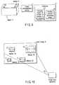
- FIG. 1is a functional block diagram showing a constitution of a three-dimensional position/orientation sensing apparatus according to a first embodiment
- FIG. 2is a functional block diagram showing a constitution of a modification example of the three-dimensional position/orientation sensing apparatus according to the first embodiment
- FIG. 3is a diagram showing a relation among a camera image plane, a camera coordinate system of an image capturing section, and an object coordinate system;
- FIG. 4Ais a diagram showing one example of a square code marker
- FIG. 4Bis a diagram showing one example of the square code marker
- FIG. 4Cis a diagram showing one example of a trapezoidal code marker
- FIG. 4Dis a diagram showing one example of a U-shaped code marker
- FIG. 4Eis a diagram showing one example of a circular code marker
- FIG. 4Fis a diagram showing another example of the circular code marker
- FIG. 4Gis a diagram showing one example of a star-shaped code marker
- FIG. 4His a diagram showing a characteristic detection result of the code marker of FIG. 4A;
- FIG. 5Ais a diagram showing one example of a circular code
- FIG. 5Bis a diagram showing one example of a triangular code
- FIG. 5Cis a diagram showing one example of a quadrangular code
- FIG. 5Dis a diagram showing another example of the quadrangular code
- FIG. 5Eis a diagram showing one example of a character code
- FIG. 5Fis a diagram showing one example of a linear code
- FIG. 5Gis a diagram showing one example of a spiral code
- FIG. 6Ais a perspective view of a symmetry/cubic mark
- FIG. 6Bis a top plan view of the symmetry/cubic mark
- FIG. 6Cis a side view of the symmetry/cubic mark
- FIG. 7is a flowchart showing a flow of operation for estimating a three-dimensional position/orientation of an object in the first embodiment
- FIG. 9is a constitution diagram of the three-dimensional position/orientation sensing apparatus according to a second embodiment.
- FIG. 10is a diagram showing one example of a screen in which an image of the marker is inputted
- FIG. 11Ais a block diagram showing a constitution of an information presenting system according to a fifth embodiment of the present invention.
- FIG. 11Bis a block diagram showing a constitution of the information presenting system according to the fifth embodiment of the present invention.
- FIG. 12is an explanatory view of an annotation display mode by the information presenting system according to the fifth embodiment.
- FIG. 13is an explanatory view of the annotation display mode by the information presenting system according to the fifth embodiment.
- FIG. 14is an explanatory view of the annotation display mode by the information presenting system according to the fifth embodiment.
- FIG. 15is an explanatory view of a mode for comparing/displaying a finished object and a design plan by the information presenting system according to the fifth embodiment
- FIG. 16is an explanatory view of the mode for comparing/displaying the finished object and the design plan by the information presenting system according to the fifth embodiment
- FIG. 17is an explanatory view of the mode for comparing/displaying the finished object and the design plan by the information presenting system according to the fifth embodiment
- FIG. 18is an explanatory view of a mode for displaying a model of a back side of a wall by the information presenting system according to the fifth embodiment
- FIG. 19is an explanatory view of the mode for comparing/displaying the finished object and the design plan by the information presenting system according to the fifth embodiment
- FIG. 20is an explanatory view of the mode for comparing/displaying the finished object and the design plan by the information presenting system according to the fifth embodiment.
- FIG. 21is an explanatory view of the mode for comparing/displaying the finished object and the design plan by the information presenting system according to the fifth embodiment.
- FIG. 1is a functional block diagram showing a constitution of a three-dimensional position/orientation sensing apparatus according to a first embodiment of the present invention.
- a plurality of inherent markers 5(hereinafter referred to as a code marker) having geometrically inherent characteristics are disposed on or in the vicinity of an object 4 whose three-dimensional position/orientation is to be estimated.
- an image capturing section 1photographs the code marker 5 , and transfers an image of the marker to a computer 2 .
- Examples of the image capturing section 1include a general TV camera, a digital video camera, and the like.
- examples of the computer 2 having received the image transferred from the image capturing section 1include a usual personal computer, a special image processing operation apparatus, and the like.
- the computer 2When the image capturing section 1 is a TV camera, and outputs an analog signal, the computer 2 includes an apparatus or a unit for digitizing the analog signal. Moreover, when the image capturing section 1 is a digital camera, a digital video camera, or the like, the section directly transfers a digital signal to the computer 2 , and the computer 2 processes the digital signal.
- the computer 2When the computer 2 receives the image of the code marker 5 captured by the image capturing section 1 , converts the image to the digital signal, and processes the digital signal, the code marker 5 in the image is recognized. When a position of the code marker 5 in the image, and a three-dimensional position of the code marker 5 registered beforehand are utilized, a three-dimensional position/orientation of the object 4 with respect to the image capturing section 1 is estimated. The three-dimensional position of the code marker 5 is stored beforehand in a memory of the computer 2 .
- the camera parameter detector 3transfers information such as a lens focal length and strain value of a camera as the image capturing section 1 to the computer 2 , and the computer 2 takes the information into consideration to estimate the three-dimensional position/orientation.
- the object 4 and image capturing section 1basically have respective inherent coordinate systems, and the image captured by the image capturing section 1 is defined as a camera image plane.
- FIG. 3is a diagram showing a relation among the camera image plane, a camera coordinate system of the image capturing section 1 , and an object coordinate system.
- an originis Om, and a three-dimensional coordinate is (xm, ym, zm).
- the originis Oc, and the three-dimensional coordinate is (xc, yc, zc).
- the camera image planeis axially constituted of a u-axis and v-axis.
- the u-axisruns in parallel with xc-axis of the camera coordinate system
- v-axisruns in parallel with yc-axis
- zc-axis for defining the camera coordinate systemagrees with an optical axis of an optical system of the image capturing section 1
- a point at which the optical axis and camera image plane intersect each other (center of the camera image plane)is defined as (u 0 , v 0 ).
- a problem of estimating the three-dimensional position/orientation of the object disposed opposite to the image capturing section 1returns to a problem of estimating the position/orientation of the object coordinate system with respect to the camera coordinate system, that is, a problem of calculating a coordinate conversion parameter to the camera coordinate system from the object coordinate system or a coordinate conversion parameter to the object coordinate system from the camera coordinate system.
- R(rij)
- t(tx, ty, tz)
- t′(t′x, t′y, t′z) denote three-dimensional translation vectors.
- the three-dimensional positions in the object coordinate systemare measured beforehand, and the positions are represented by (xi m , yi m , zi m ). Moreover, an in-image position is represented by (ui, vi).
- (u 0 , v 0 )denotes a center in the image
- ( ⁇ u, ⁇ v)denotes an expansion ratio in u-direction and v-direction
- theyare camera internal parameters regarding the image capturing section 1 , and the values can be estimated by camera calibration.
- the computer 2having received the image extracts a prospective region estimated as a region corresponding to the code marker 5 from the image (stop S 1 ).
- the computeranalyzes the inside of the prospective region extracted in the step S 1 in detail, extracts a geometric characteristic corresponding to a code of the code marker 5 from the region, sets the region as a marker region when the code is recognized, and registers an in-image position and code (step S 2 ). Subsequently, the computer utilizes an in-image two-dimensional position of the code marker 5 extracted from the registered image and the three-dimensional position of the marker with respect to the object to calculate the position of the object with respect to the image capturing section 1 (step S 3 ).
- the image capturing section 1generates a color image
- the code markers 5 shown in FIGS. 4A to 4 H, FIGS. 5A to 5 G, FIGS. 6A to 6 Care assumed.
- the following three vectorsare calculated from filter measured values R (red), G (green), B (blue) constituting the color image with respect to an image point defined by an image plane (u, v).
- the values of imin, imax, rmin, rmax, gmin, gmax, and the likeare set beforehand.
- the region corresponding to the code marker 5is determined by filling holes in the image region.
- the imageis compared with the marker image registered beforehand by pattern matching, so that the marker can be judged.
- the method introduced by this documentcomprises selecting three arbitrary markers which are not disposed in a straight line from a group of identified markers, and utilizing the three code markers to calculate a prospective solution of the coordinate conversion parameter between the camera coordinate system and the object coordinate system.
- the non-selected marker groupis utilized with respect to each of the four solutions to verify the solution, the solution is selected and used as an initial value, and all the code markers are utilized to update the solution.
- Three code markers which are not arranged in the straight line in the imageare selected from the identified marker group according to a certain selection standard.
- the selection standardthere is supposedly a method of selecting three code markers such that an area of a triangle having vertexes formed by the three code markers is maximum or minimum in the camera image plane.
- distances R 12 , R 23 , R 31 and angles ⁇ 12 , ⁇ 23 , ⁇ 31have known values, but d 1 , d 2 , d 3 have unknown values.
- the coordinate conversion parameter to the camera coordinate system from the object coordinate systemcan be calculated.
- the distance R 12is calculated as Euclidean distance between points P 1 and P 2 .
- the distances R 23 , and R 31are calculated as Euclidean distances between points P 2 and P 3 , and P 3 and P 1 , respectively.
- the angle ⁇ ij formed by the markers M 1 , M 2 and origin Oc of the camera coordinate systemcan be calculated as follows.
- the three anglescan be calculated from cosine in this manner.
- R 12d 1 2 +d 2 2 ⁇ 2 d 1 d 2 cos ⁇ 12
- R 23d 2 2 +d 3 2 ⁇ 2 d 2 d 3 cos ⁇ 23
- dist(k)is calculated by the following method.
- the square error ejcan be calculated as follows.
- the solution cHm(k) selected in the above (4)is estimated from the code markers M 1 , M 2 , M 3 , and measured values with respect to the other markers M 4 , M 5 , . . . , Mm are not utilized.
- H m c[ cos ⁇ ⁇ ⁇ z ⁇ cos ⁇ ⁇ ⁇ y ⁇ cos ⁇ ⁇ ⁇ x ⁇ sin ⁇ ⁇ ⁇ y ⁇ sin ⁇ ⁇ ⁇ x - sin ⁇ ⁇ ⁇ x ⁇ cos ⁇ ⁇ ⁇ x ⁇ cos ⁇ ⁇ ⁇ x ⁇ sin ⁇ ⁇ ⁇ y ⁇ cos ⁇ ⁇ ⁇ x + sin ⁇ ⁇ ⁇ z ⁇ sin ⁇ ⁇ ⁇ x t x sin ⁇ ⁇ ⁇ x ⁇ cos ⁇ ⁇ ⁇ y ⁇ sin ⁇ ⁇ ⁇ z ⁇ sin ⁇ ⁇ ⁇ y ⁇ sin ⁇ ⁇ ⁇ ⁇ x + cos ⁇ ⁇ ⁇ z ⁇ cos ⁇ ⁇ ⁇ x ⁇ cos ⁇ ⁇ ⁇ x ⁇ sin ⁇ ⁇ ⁇ ⁇ x + cos ⁇
- All marker measured valuesare utilized to update the six-dimensional parameter in this manner, and the coordinate conversion parameter to the camera coordinate system from the object coordinate system is calculated. That is, the position relation between the object 4 and the image capturing section 1 can be calculated.
- Each code marker 5has a geometric characteristic, and this is important in that a code sufficient for adding a label to the code marker 5 can be generated.
- FIGS. 4A to 4 Hshow shapes of the code marker which are preferable for analyzing one marker image and recognizing four characteristic points
- FIGS. 4A, 4 Bshow constitution examples of a square code marker
- FIG. 4Cshows one example of a trapezoidal code marker
- FIG. 4Dshows one example of a U-shaped code marker
- FIGS. 4E, 4 Fshow examples of a circular code marker
- FIG. 4Gshows one example of a star-shaped code marker.
- FIG. 4Hshows that the characteristic points of the code marker (FIG. 4A) are detected.
- a coordinate value in an object coordinate of a lower left end of the outer frameis set to (u 1 , v 1 ).
- the coordinate values of a right lower end, right upper end, and left upper end of the outer frameare set to (u 2 , v 2 ), (u 3 , v 3 ), and (u 4 , v 4 ) in order.
- These four coordinate valuesare assigned to M 1 to M 4 described above, and it is possible to recognize the position/orientation of the object.
- the code marker of FIG. 4Bis similar to that of FIG. 4A except gnat the characteristic points are detected by detecting tour points in the four corners inside the outer frame.
- FIGS. 5A to 5 Gshow variations of the shape of the code inside the outer frame in which 8-bit information is stored. That is, the 8-bit information is stored by a circular code in FIG. 5A, a triangular code in FIG. 5B, a quadrangular code in FIGS. 5C, 5 D, a character code in FIG. 5E, a linear code in FIG. 5F, and a spiral code in FIG. 5 G. Additionally, it goes without saying that the code is not limited to these shapes.
- FIGS. 6A to 6 Cshow examples of a symmetry/cubic mark (hemispherical, pyramid shape). In the examples, even when the object is captured from an oblique direction, a recognition ratio is high.
- FIG. 6Ais a perspective view
- FIG. 6Bis a top plan view
- FIG. 6Cis a side view.
- the markerscan be used as information indicating attributes of places such as a room including a room number, corridor, and stairs of a building.
- the markeris constituted of self-emission type materials such as LED and LCD, and the self-emission type material is controlled, or the marker is projected by a projector as occasion demands. Then, the marker is not statically changed, and a dynamic marker can be constructed such that the marker can be changed according to the occasion.
- the self-emission type materialmay be lit in synchronization of an alarm lamp in case of emergency or disaster. In this case, the marker can be used as an automatic guide lamp during disaster.
- the markerWhen the marker is constituted of a fluorescent material, the marker can operate even without lighting. Furthermore, the marker may be constructed with an infrared or ultraviolet wavelength which is sensitive to a projector, and the marker can operate in an invisible state to human eyes without impairing appearance.
- one of a plurality of markersis analyzed.
- FIG. 9is an explanatory view of the second embodiment.
- the changing means 21analyzes, for example, the marker 5 positioned in a leftmost upper portion of a screen out of a plurality of found markers 5 , and transfers the coordinate of the characteristic point detected from the outer frame to position/orientation estimating means 22 .
- the changing meanstransfers the coordinate of the identified marker 5 to the position/orientation estimating means 22 . Since an operation of the position/orientation estimating means 22 is described in detail in the first embodiment, description thereof is omitted.
- the changing means 21 of the number of markers to be analyzed in the second embodimentoperates in accordance with a visual field angle in the screen of the marker.
- a visual field anglean angle of the marker which occupies in a horizontal angle of the screen.
- FIG. 10shows a screen in which the image of the marker is inputted.
- a screen angle of a horizontal directionis 40 degrees, and visual field angles of markers 30 to 33 occupying the screen in the horizontal direction are 15 , 3 , 5 , 5 angles, respectively.
- the position/orientation sensingis switched between the sensing by the single marker and by four markers in the screen in accordance with the visual field angle of the marker 30 which has a largest visual field angle among the markers. It is now assumed that a threshold value for changing the sensing is 10 degrees.
- the sensing by the single markeris performed.
- the sensing by the plurality of markersis performed.
- the sensing by the plurality of markersis performed.
- the sensingcan be changed in accordance with a visual field angle of a vertical direction, or an area occupied in the image in both directions.
- Thisrelates to a method of estimating the three-dimensional position/orientation between the component other than the image capturing section 1 and the object 4 .
- the example for measuring the position relation between the object 4 and the image capturing section 1has been described.
- the image capturing section 1 and computer 2 shown in FIG. 1are utilized as a position sensor for estimating the position/orientation of the object 4 .
- another apparatusis disposed in a system including the position sensor, and a coordinate defined by the apparatus is considered to be a system coordinate as a reference of the system in many cases.
- the computer 2stores the coordinate conversion parameter from the camera coordinate system defined by the image capturing section 1 to the reference coordinate system defined by another apparatus beforehand.
- the computer 2utilizes the coordinate conversion parameter to calculate the coordinate conversion parameter to the reference coordinate system from the object coordinate system. Moreover, the three-dimensional position/orientation of the object 4 in the reference coordinate system is estimated.
- the means of the present inventioncan also be utilized as the position/orientation sensor for another apparatus.
- claimed image input meansis a concept included in the image capturing section 1 .
- Identifying means, position/orientation detecting means by the single marker, position/orientation detecting means by a plurality of markers, and changing meansare concepts included in the computer 2 .
- the image obtained by capturing the marker having the known position/orientation relation with the objectis analyzed, a relative position/orientation relation between the marker and capturing means is obtained, and the relation is used to obtain the position and orientation of the object.
- a three-dimensional position/orientation sensing apparatus for measurement in a relatively broad regionthere can be provided.
- FIGS. 11A, 11 Bare block diagrams showing a constitution of an information presenting system according to a fifth embodiment of the present invention.
- an output of the image input section 1is connected to inputs of a three-dimensional position/orientation relation detector 2 , model data superimposing display 3 , and camera parameter acquiring section 4 .
- Outputs of the three-dimensional position/orientation relation detector 2 and camera parameter acquiring section 4are connected to an input of an information database 5 .
- outputs of the information database 5 and object indicator 6are connected to the input of the model data superimposing display 3 .
- the output of the image input section 1is connected to the inputs of the three-dimensional position/orientation relation detector 2 , model data superimposing display 3 , and camera parameter acquiring section 4 .
- the outputs of the three-dimensional position/orientation relation detector 2 and camera parameter acquiring section 4are connected to the input of the information database 5 .
- the outputs of the information database 5 and image input section 1are connected to the input of the model data superimposing display 3 .
- the output of the object indicator 6is connected to the input of the three-dimensional position/orientation relation detector 2 .
- FIG. 11Ashows a constitution example of two-dimensional pointing by the object indicator 6 on a display screen (two-dimensionally projected screen) of the model data superimposing display 3
- FIG. 11Bshows a constitution example of indication by a laser pointer as the object indicator 6 in a real space for pointing in the three-dimensional coordinate.
- the marker having the known three-dimensional position relation with the objectis captured by the capturing apparatus (not shown), and the image of the marker is inputted to the present system via the image input section 1 .
- the three-dimensional position/orientation relation detector 2uses the position of the marker on the image to obtain the position/orientation relation between the object and the capturing apparatus.
- the model data superimposing display 3displays a real image of the object inputted via the image input section 1 , and superimposes/displays three-dimensional model data of the object with a position, size and direction based on the position/orientation relation.
- attribute information of a desired object indicated by the object indicator 6 in the screen of the model data superimposing display 3can also be superimposed/displayed in the model data superimposing display 3 by appropriately referring to the information database 5 .
- the attribute informationincludes a name display of the object, and a code for indicating the object from the name display, such as a pointer.
- a display position of the attribute informationmay be set by the object indicator 6 so that the displays of various attribute information do not interfere with each other.
- the three-dimensional model data or the attribute informationis superimposed/displayed on the screen with a color different from a display color of the object.
- the data or the informationmay also be displayed on a wall surface or a ceiling surface around the object on the image.
- the three-dimensional model datais displayed in a coated surface in which a background is seen through.
- the three-dimensional model datacan be displayed in the model data superimposing display 3 , even when the object is shielded by a shielding material, and is not displayed in the image.
- a display modewill be described later with reference to the drawing.
- the three-dimensional position/orientation relation detector 2recognizes the marker in the image inputted to the present system via the image input section 1 , and obtains the position/orientation relation between the capturing apparatus and the object. Since the method is already proposed by Jpn. Pat. Appln. KOKAI Publication No. 2000-227309 by the present applicant, description thereof is omitted.
- a visual marker disposed on or in the vicinity of the objectmay be employed as the marker.
- the visual markerhas a broader detectable range as compared with a magnetic or acoustic marker.
- a marker invisible to human eyescan be employed.
- the position/orientation relationcan also be obtained by detecting the characteristic point of the object.
- the marker projected onto the object by the projectorcan also be used.
- the live video imageis displayed in the model data superimposing display 3 .
- the three-dimensional position/orientation relation detector 2recognizes the information of the marker in the live video image, starts estimating the position/orientation of the camera, reads names of all objects (in which associated data exists) in the visual field from the information database 5 , and superimposes/displays the names in the model data superimposing display 3 .
- a useroperates the object indicator 6 such as a mouse and track ball in this state to indicate the object (e.g., warm water (feed) 2 ) whose detailed data is to be displayed.
- object indicator 6such as a mouse and track ball in this state to indicate the object (e.g., warm water (feed) 2 ) whose detailed data is to be displayed.
- member attribute informationis displayed in a right upper portion of the screen
- repair history informationis displayed in a right lower portion of the screen
- system informationis displayed in a lower portion of the screen.
- 3D model data of a piping model as the selected objectis superimposed/displayed on the live video image.
- a wire frame displayis performed with respect to the selected object.
- the imageis displayed based on a predetermined camera parameter from the camera parameter acquiring section 4 in the model data superimposing display 3 .
- FIGS. 15 to 17A mode for comparing/displaying a finished object and a design plan will next be described with reference to FIGS. 15 to 17 .
- the live video imageis inputted from the camera via the image input section 1 in this mode, as shown in FIG. 15, the live video image is displayed in the model data superimposing display 3 .
- the three-dimensional position/orientation relation detector 2recognizes marker information in the live video image, starts estimating the position/orientation of the camera, and superimposes/displays the 3D model data of all the objects (in which the associated data exists) in the visual field in a translucent state on the live video Additionally, transmittance of the 3D model dots can appropriately be adjusted.
- the live video imageis shown by a fine line
- the 3D model datais displayed by a bold line.
- the userwatches the display of the model data superimposing display 3 , and can compare the finished object of the live video image with the 3D model data generated from the design plan.
- the useroperates the object indicator 6 such as the mouse and track ball in this state to indicate the object whose detailed data is to be displayed.
- the member attribute informationis displayed in the right upper portion of the screen
- the repair history informationis displayed in the right lower portion of the screen
- the system informationis displayed in the lower portion of the screen.
- the associated file name, type, apparatus number, model number, object name, work type, length and number, and the like of the selected objectare displayed as the member attribute information.
- repair date and content of the selected objectare displayed as the repair history information
- the camera position and object positionare displayed as the system information. These are displayed in the text file.
- the 3D model data of the piping model as the selected objectis superimposed/displayed in a wire frame display on the live video image. Furthermore, in FIG. 15, the 3D model data is superimposed/displayed in the translucent state. However, the 3D model data can all be displayed in the wire frame as shown in FIG. 17 .
- a mode for displaying a model of a back side of a wallwill next be described with reference to FIGS. 18 to 21 .
- the three-dimensional position/orientation relation detector 2starts estimating the position/orientation of the camera, and superimposes/displays the 3D model data in the model data superimposing display 3 as shown in FIG. 19 .
- the names of all the objectsare read from the information database 5 , and superimposed/displayed in the model data superimposing display 3 That is, “warm water (feed) 2 ”, “warm water (return) 2 ”, “air conditioner (return) 1 ”, and “air conditioner (feed) 1 ” are superimposed/displayed as the names.
- the useroperates the object indicator 6 such as the mouse and track ball in this state to indicate the object whose detailed data is to be displayed.
- the member attribute informationis displayed in the right upper portion of the screen
- the repair history informationis displayed in the right lower portion of the screen
- the system informationis displayed in the lower portion of the screen.
- the associated file name, type, apparatus number, model number, object name, work type, length and number, and the like of the selected objectare displayed as the member attribute information.
- the repair date and content of the selected objectare displayed as the repair history information.
- the camera position and object positionare displayed as the system information. These are displayed in the text file.
- the 3D model data of the piping model as the selected objectis superimposed/displayed in the wire frame display by operating the object indicator 6 such as the mouse.
- a model error detecting system for detecting a dynamic errorwill next be described in detail as a sixth embodiment of the present invention.
- the registered positionis corrected by the following method.
- an object model Mis displayed on the screen in accordance with the registered position of the object in the reference point coordinate.
- an actual object Ris captured, and superimposed upon the model.
- a side length, thickness, and other constitutions of the object R in the imageare recognized, and compared with those of the object model M, a difference between the object and the model is obtained, and an error E is obtained on a projected screen. That is, an object region is extracted from the object R, and an element constituting the object R is fined/thinned.
- a difference between the thinned object R and the object model Mis obtained, and recognized, and the error B is measured.
- This error Ecan be measured, for example, by the following method.
- the methodfirst comprises using the mouse or another pointing device to indicate points as comparison objects in the object R and object model M, obtaining a difference of coordinate of the point, and obtaining an error in a two-dimensional projection coordinate in a visual field direction.
- images from a plurality of directionsare used to perform the processing of obtaining the error in the two-dimensional projection coordinate in the visual field direction in the position designated by the pointing device as indicating means.
- a three-dimensional error(cubic error data) can be obtained.
- the methodcomprises taking the image of the object R into the computer by an image take-in section, and matching patterns of the image obtained by two-dimensionally projecting the three-dimensional model data of the object R and the image of the object R, so that the error E can be detected.
- the error E of the position coordinate datacan be obtained by using the measuring device to measure the distance between the capturing apparatus and the object R, and comparing the distance with the distance between the object R and the capturing apparatus registered as the three-dimensional model in the reference point coordinate.
- an information presenting system and model error detecting systemin which it is easy to compare the captured image of the actual object with the object data.
Landscapes
- Physics & Mathematics (AREA)
- General Physics & Mathematics (AREA)
- Engineering & Computer Science (AREA)
- Multimedia (AREA)
- Radar, Positioning & Navigation (AREA)
- Remote Sensing (AREA)
- Length Measuring Devices By Optical Means (AREA)
Abstract
Description


Claims (45)
Applications Claiming Priority (4)
| Application Number | Priority Date | Filing Date | Title |
|---|---|---|---|
| JP2000283292AJP4537557B2 (en) | 2000-09-19 | 2000-09-19 | Information presentation system |
| JP2000-284318 | 2000-09-19 | ||
| JP2000-283292 | 2000-09-19 | ||
| JP2000284318AJP4282216B2 (en) | 2000-09-19 | 2000-09-19 | 3D position and orientation sensing device |
Publications (2)
| Publication Number | Publication Date |
|---|---|
| US20020052709A1 US20020052709A1 (en) | 2002-05-02 |
| US6697761B2true US6697761B2 (en) | 2004-02-24 |
Family
ID=26600209
Family Applications (1)
| Application Number | Title | Priority Date | Filing Date |
|---|---|---|---|
| US09/951,873Expired - LifetimeUS6697761B2 (en) | 2000-09-19 | 2001-09-13 | Three-dimensional position/orientation sensing apparatus, information presenting system, and model error detecting system |
Country Status (1)
| Country | Link |
|---|---|
| US (1) | US6697761B2 (en) |
Cited By (85)
| Publication number | Priority date | Publication date | Assignee | Title |
|---|---|---|---|---|
| US20020145709A1 (en)* | 2000-09-19 | 2002-10-10 | Olympus Optical Co., Ltd. | System for displaying information in specific region |
| US20040201823A1 (en)* | 2003-04-11 | 2004-10-14 | Ramesh Raskar | Context aware projector |
| US20040220767A1 (en)* | 2003-05-02 | 2004-11-04 | Canon Kabushiki Kaisha | Image processing method and apparatus therefor |
| US20040249594A1 (en)* | 2002-03-19 | 2004-12-09 | Canon Kabushiki Kaisha | Sensor calibration apparatus, sensor calibration method, program, storage medium, information processing method, and information processing apparatus |
| US20050054916A1 (en)* | 2003-09-05 | 2005-03-10 | Varian Medical Systems Technologies, Inc. | Systems and methods for gating medical procedures |
| US20050069172A1 (en)* | 2003-09-30 | 2005-03-31 | Canon Kabushiki Kaisha | Index identifying method and system |
| US20050069196A1 (en)* | 2003-09-30 | 2005-03-31 | Canon Kabushiki Kaisha | Index identification method and apparatus |
| US20050195587A1 (en)* | 2004-03-08 | 2005-09-08 | Moctezuma De La Barrera Jose L. | Enhanced illumination device and method |
| US20050201510A1 (en)* | 1998-10-23 | 2005-09-15 | Hassan Mostafavi | Method and system for predictive physiological gating |
| US20060094955A1 (en)* | 2004-11-04 | 2006-05-04 | Canon Kabushiki Kaisha | Method and apparatus for processing information |
| US20060184013A1 (en)* | 2004-12-14 | 2006-08-17 | Sky-Trax Incorporated | Method and apparatus for determining position and rotational orientation of an object |
| US20070297695A1 (en)* | 2006-06-23 | 2007-12-27 | Canon Kabushiki Kaisha | Information processing method and apparatus for calculating information regarding measurement target on the basis of captured images |
| US20080136813A1 (en)* | 2006-11-07 | 2008-06-12 | Gunter Goldbach | Method and system for region of interest calibration parameter adjustment of tracking systems |
| US7487045B1 (en) | 2005-03-10 | 2009-02-03 | William Vieira | Projected score area calculator and method of use |
| US20090180667A1 (en)* | 2008-01-14 | 2009-07-16 | Mahan Larry G | Optical position marker apparatus |
| US20090198371A1 (en)* | 2008-02-01 | 2009-08-06 | Emanuel David C | Apparatus and method for asset tracking |
| US7620146B2 (en) | 1998-10-23 | 2009-11-17 | Varian Medical Systems, Inc. | Systems and methods for processing x-ray images |
| US20090323121A1 (en)* | 2005-09-09 | 2009-12-31 | Robert Jan Valkenburg | A 3D Scene Scanner and a Position and Orientation System |
| US20100165332A1 (en)* | 2005-09-28 | 2010-07-01 | Hunter Engineering Company | Method and Apparatus For Vehicle Service System Optical Target Assembly |
| US7769430B2 (en) | 2001-06-26 | 2010-08-03 | Varian Medical Systems, Inc. | Patient visual instruction techniques for synchronizing breathing with a medical procedure |
| US20110001821A1 (en)* | 2005-09-28 | 2011-01-06 | Hunter Engineering Company | Method and Apparatus For Vehicle Service System Optical Target Assembly |
| US20110010023A1 (en)* | 2005-12-03 | 2011-01-13 | Kunzig Robert S | Method and apparatus for managing and controlling manned and automated utility vehicles |
| US20110069019A1 (en)* | 2009-07-08 | 2011-03-24 | Smart Technologies Ulc | Method for manipulating a graphic widget in a three-dimensional environment displayed on a touch panel of an interactive input system |
| US20110102605A1 (en)* | 2009-11-02 | 2011-05-05 | Empire Technology Development Llc | Image matching to augment reality |
| US20110185584A1 (en)* | 2007-05-21 | 2011-08-04 | Snap-On Incorporated | Method and apparatus for wheel alignment |
| US20110317173A1 (en)* | 2010-06-23 | 2011-12-29 | Naoki Koike | Position measuring device |
| US20120052973A1 (en)* | 2010-08-26 | 2012-03-01 | Michael Bentley | Motion capture element mount |
| WO2012167110A3 (en)* | 2011-06-02 | 2013-02-07 | Honda Motor Co., Ltd. | Target recognition and localization methods using a laser sensor for wheeled mobile robots |
| US20130222672A1 (en)* | 2010-06-28 | 2013-08-29 | Ji Hea KIM | Method and apparatus for providing the operation state of an external device |
| US20130249906A1 (en)* | 2012-03-23 | 2013-09-26 | Benjamin Gunderson | Method for indicating annotations associated with a particular display view of a three-dimensional model independent of any display view |
| US8788020B2 (en) | 1998-10-23 | 2014-07-22 | Varian Medical Systems, Inc. | Method and system for radiation application |
| US9101994B2 (en) | 2011-08-10 | 2015-08-11 | Illinois Tool Works Inc. | System and device for welding training |
| US9352411B2 (en) | 2008-05-28 | 2016-05-31 | Illinois Tool Works Inc. | Welding training system |
| US9368045B2 (en) | 2012-11-09 | 2016-06-14 | Illinois Tool Works Inc. | System and device for welding training |
| US9511443B2 (en) | 2012-02-10 | 2016-12-06 | Illinois Tool Works Inc. | Helmet-integrated weld travel speed sensing system and method |
| US9558584B1 (en)* | 2013-07-29 | 2017-01-31 | Google Inc. | 3D position estimation of objects from a monocular camera using a set of known 3D points on an underlying surface |
| US9583014B2 (en) | 2012-11-09 | 2017-02-28 | Illinois Tool Works Inc. | System and device for welding training |
| US9583023B2 (en) | 2013-03-15 | 2017-02-28 | Illinois Tool Works Inc. | Welding torch for a welding training system |
| US9589481B2 (en) | 2014-01-07 | 2017-03-07 | Illinois Tool Works Inc. | Welding software for detection and control of devices and for analysis of data |
| US9622361B2 (en) | 2010-08-26 | 2017-04-11 | Blast Motion Inc. | Enclosure and mount for motion capture element |
| US9643049B2 (en) | 2010-08-26 | 2017-05-09 | Blast Motion Inc. | Shatter proof enclosure and mount for a motion capture element |
| US9666100B2 (en) | 2013-03-15 | 2017-05-30 | Illinois Tool Works Inc. | Calibration devices for a welding training system |
| US9672757B2 (en) | 2013-03-15 | 2017-06-06 | Illinois Tool Works Inc. | Multi-mode software and method for a welding training system |
| US9713852B2 (en) | 2013-03-15 | 2017-07-25 | Illinois Tool Works Inc. | Welding training systems and devices |
| US9724787B2 (en) | 2014-08-07 | 2017-08-08 | Illinois Tool Works Inc. | System and method of monitoring a welding environment |
| US9728103B2 (en) | 2013-03-15 | 2017-08-08 | Illinois Tool Works Inc. | Data storage and analysis for a welding training system |
| US9724788B2 (en) | 2014-01-07 | 2017-08-08 | Illinois Tool Works Inc. | Electrical assemblies for a welding system |
| US9747680B2 (en) | 2013-11-27 | 2017-08-29 | Industrial Technology Research Institute | Inspection apparatus, method, and computer program product for machine vision inspection |
| US9746354B2 (en) | 2010-08-26 | 2017-08-29 | Blast Motion Inc. | Elastomer encased motion sensor package |
| US9751149B2 (en) | 2014-01-07 | 2017-09-05 | Illinois Tool Works Inc. | Welding stand for a welding system |
| US9757819B2 (en) | 2014-01-07 | 2017-09-12 | Illinois Tool Works Inc. | Calibration tool and method for a welding system |
| US9862049B2 (en) | 2014-06-27 | 2018-01-09 | Illinois Tool Works Inc. | System and method of welding system operator identification |
| US9864062B2 (en) | 2012-09-07 | 2018-01-09 | Leica Geosystems Ag | Laser tracker with hybrid imaging method for extending the measuring range |
| US9875665B2 (en) | 2014-08-18 | 2018-01-23 | Illinois Tool Works Inc. | Weld training system and method |
| US9937578B2 (en) | 2014-06-27 | 2018-04-10 | Illinois Tool Works Inc. | System and method for remote welding training |
| US10056010B2 (en) | 2013-12-03 | 2018-08-21 | Illinois Tool Works Inc. | Systems and methods for a weld training system |
| US10105782B2 (en) | 2014-01-07 | 2018-10-23 | Illinois Tool Works Inc. | Feedback from a welding torch of a welding system |
| US10170019B2 (en) | 2014-01-07 | 2019-01-01 | Illinois Tool Works Inc. | Feedback from a welding torch of a welding system |
| US10204406B2 (en) | 2014-11-05 | 2019-02-12 | Illinois Tool Works Inc. | System and method of controlling welding system camera exposure and marker illumination |
| US10210773B2 (en) | 2014-11-05 | 2019-02-19 | Illinois Tool Works Inc. | System and method for welding torch display |
| US10239147B2 (en) | 2014-10-16 | 2019-03-26 | Illinois Tool Works Inc. | Sensor-based power controls for a welding system |
| US10254139B2 (en) | 2010-08-26 | 2019-04-09 | Blast Motion Inc. | Method of coupling a motion sensor to a piece of equipment |
| US10307853B2 (en) | 2014-06-27 | 2019-06-04 | Illinois Tool Works Inc. | System and method for managing welding data |
| US10373304B2 (en) | 2014-11-05 | 2019-08-06 | Illinois Tool Works Inc. | System and method of arranging welding device markers |
| US10373517B2 (en) | 2015-08-12 | 2019-08-06 | Illinois Tool Works Inc. | Simulation stick welding electrode holder systems and methods |
| US20190260944A1 (en)* | 2018-02-20 | 2019-08-22 | Canon Kabushiki Kaisha | Image capture apparatus and method for controlling the same |
| US10402959B2 (en) | 2014-11-05 | 2019-09-03 | Illinois Tool Works Inc. | System and method of active torch marker control |
| US10417934B2 (en) | 2014-11-05 | 2019-09-17 | Illinois Tool Works Inc. | System and method of reviewing weld data |
| US10427239B2 (en) | 2015-04-02 | 2019-10-01 | Illinois Tool Works Inc. | Systems and methods for tracking weld training arc parameters |
| US10438505B2 (en) | 2015-08-12 | 2019-10-08 | Illinois Tool Works | Welding training system interface |
| US10490098B2 (en) | 2014-11-05 | 2019-11-26 | Illinois Tool Works Inc. | System and method of recording multi-run data |
| US10506219B2 (en) | 2016-11-29 | 2019-12-10 | Samsung Electronics Co., Ltd. | Method and apparatus for determining interpupillary distance (IPD) |
| DE102018113840A1 (en)* | 2018-06-11 | 2019-12-12 | Osram Gmbh | LABELING AND SYSTEM FOR POSITIONING AND / OR ENVIRONMENTAL DETERMINATION AND DEVICE AND METHOD FOR DETERMINING POSITION AND / OR FOR DISPLAYING AR-CONTENT |
| US10593230B2 (en) | 2015-08-12 | 2020-03-17 | Illinois Tool Works Inc. | Stick welding electrode holder systems and methods |
| US10657839B2 (en) | 2015-08-12 | 2020-05-19 | Illinois Tool Works Inc. | Stick welding electrode holders with real-time feedback features |
| US10665128B2 (en) | 2014-06-27 | 2020-05-26 | Illinois Tool Works Inc. | System and method of monitoring welding information |
| US10671158B2 (en) | 2016-11-22 | 2020-06-02 | Samsung Electronics Co., Ltd. | Three-dimensional (3D) rendering method and apparatus for user' eyes |
| US10667727B2 (en) | 2008-09-05 | 2020-06-02 | Varian Medical Systems, Inc. | Systems and methods for determining a state of a patient |
| US11014183B2 (en) | 2014-08-07 | 2021-05-25 | Illinois Tool Works Inc. | System and method of marking a welding workpiece |
| US11090753B2 (en) | 2013-06-21 | 2021-08-17 | Illinois Tool Works Inc. | System and method for determining weld travel speed |
| US11247289B2 (en) | 2014-10-16 | 2022-02-15 | Illinois Tool Works Inc. | Remote power supply parameter adjustment |
| US11288978B2 (en) | 2019-07-22 | 2022-03-29 | Illinois Tool Works Inc. | Gas tungsten arc welding training systems |
| US11538193B2 (en) | 2020-01-10 | 2022-12-27 | Aptiv Technologies Limited | Methods and systems for calibrating a camera |
| US11776423B2 (en) | 2019-07-22 | 2023-10-03 | Illinois Tool Works Inc. | Connection boxes for gas tungsten arc welding training systems |
| US12242916B2 (en) | 2017-11-17 | 2025-03-04 | Divine Logic, Inc. | Systems and methods for tracking items |
Families Citing this family (58)
| Publication number | Priority date | Publication date | Assignee | Title |
|---|---|---|---|---|
| AU2003258898A1 (en)* | 2002-08-09 | 2004-02-25 | Surveylab Group Limited | Mobile instrument, viewing device, and methods of processing and storing information |
| DE10318390A1 (en)* | 2003-04-23 | 2004-12-30 | Volkswagen Ag | Method, device and computer program product for the virtual positioning of components |
| JP3864150B2 (en)* | 2003-06-18 | 2006-12-27 | オリンパス株式会社 | Information presentation device and information presentation method |
| EP1653191A4 (en)* | 2003-07-11 | 2010-09-08 | Olympus Corp | Information presentation device and information presentation system using the same |
| US20050083417A1 (en)* | 2003-10-21 | 2005-04-21 | Battles Amy E. | System and method for providing image orientation information of a video clip |
| US7809159B2 (en)* | 2003-10-30 | 2010-10-05 | Nec Corporation | Estimation system, estimation method, and estimation program for estimating object state |
| WO2006075331A2 (en)* | 2005-01-13 | 2006-07-20 | Mazor Surgical Technologies Ltd. | Image-guided robotic system for keyhole neurosurgery |
| JP4914019B2 (en)* | 2005-04-06 | 2012-04-11 | キヤノン株式会社 | Position and orientation measurement method and apparatus |
| JP5084167B2 (en)* | 2006-03-31 | 2012-11-28 | キヤノン株式会社 | Position and orientation measurement method and apparatus |
| DE102006021063B3 (en)* | 2006-05-03 | 2007-09-06 | Aicon 3D Systems Gmbh | Marking body for three-dimensional photogrammetry measurement of test object, has dice surfaces providing marking using four marking units, where positions of marking units are known to each other |
| CN105373792A (en)* | 2007-05-21 | 2016-03-02 | 实耐宝公司 | Wheel alignment method and wheel alignment equipment |
| DE102007039077A1 (en)* | 2007-08-19 | 2009-03-05 | Fachhochschule Gießen-Friedberg | Signal marks and methods for the photogrammetric measurement of geometrically irregular objects |
| EP2250623A4 (en) | 2008-03-05 | 2011-03-23 | Ebay Inc | Method and apparatus for image recognition services |
| US9495386B2 (en) | 2008-03-05 | 2016-11-15 | Ebay Inc. | Identification of items depicted in images |
| DE102008001629A1 (en)* | 2008-05-07 | 2009-11-12 | Robert Bosch Gmbh | Projection means comprehensive device |
| US8433128B2 (en)* | 2008-11-04 | 2013-04-30 | Omron Corporation | Method of creating three-dimensional model and object recognizing device |
| DE102009050474B4 (en)* | 2009-10-23 | 2013-08-29 | Testo Ag | Imaging inspection device |
| JP5427577B2 (en)* | 2009-12-04 | 2014-02-26 | パナソニック株式会社 | Display control apparatus and display image forming method |
| US9164577B2 (en)* | 2009-12-22 | 2015-10-20 | Ebay Inc. | Augmented reality system, method, and apparatus for displaying an item image in a contextual environment |
| US10127606B2 (en) | 2010-10-13 | 2018-11-13 | Ebay Inc. | Augmented reality system and method for visualizing an item |
| US8561897B2 (en)* | 2010-11-18 | 2013-10-22 | Sky-Trax, Inc. | Load tracking utilizing load identifying indicia and spatial discrimination |
| EP2455855A1 (en)* | 2010-11-22 | 2012-05-23 | Siemens AG | Graphical comparison display of software |
| JP5633345B2 (en)* | 2010-12-03 | 2014-12-03 | 富士通株式会社 | Image processing apparatus, image display system, and image processing program |
| US8843350B2 (en)* | 2011-06-03 | 2014-09-23 | Walter P. Moore and Associates, Inc. | Facilities management system |
| WO2012172548A1 (en)* | 2011-06-14 | 2012-12-20 | Youval Nehmadi | Method for translating a movement and an orientation of a predefined object into a computer generated data |
| US10242456B2 (en)* | 2011-06-23 | 2019-03-26 | Limitless Computing, Inc. | Digitally encoded marker-based augmented reality (AR) |
| US9449342B2 (en) | 2011-10-27 | 2016-09-20 | Ebay Inc. | System and method for visualization of items in an environment using augmented reality |
| US9626798B2 (en)* | 2011-12-05 | 2017-04-18 | At&T Intellectual Property I, L.P. | System and method to digitally replace objects in images or video |
| US9240059B2 (en) | 2011-12-29 | 2016-01-19 | Ebay Inc. | Personal augmented reality |
| EP2822472B1 (en) | 2012-03-07 | 2022-09-28 | Ziteo, Inc. | Systems for tracking and guiding sensors and instruments |
| CN102841679B (en)* | 2012-05-14 | 2015-02-04 | 乐金电子研发中心(上海)有限公司 | Non-contact man-machine interaction method and device |
| DE102012208132A1 (en)* | 2012-05-15 | 2013-11-21 | Bayerische Motoren Werke Aktiengesellschaft | Method for vehicle localization |
| US10846766B2 (en) | 2012-06-29 | 2020-11-24 | Ebay Inc. | Contextual menus based on image recognition |
| US10380469B2 (en) | 2012-07-18 | 2019-08-13 | The Boeing Company | Method for tracking a device in a landmark-based reference system |
| US9448758B2 (en)* | 2012-07-18 | 2016-09-20 | The Boeing Company | Projecting airplane location specific maintenance history using optical reference points |
| US9336541B2 (en) | 2012-09-21 | 2016-05-10 | Paypal, Inc. | Augmented reality product instructions, tutorials and visualizations |
| US10378877B2 (en) | 2012-11-02 | 2019-08-13 | Sony Corporation | Image processing device, image processing method, and program |
| DE102012221921B4 (en)* | 2012-11-29 | 2018-04-05 | Technische Hochschule Wildau (Fh) | Locate a mobile device using optically detectable landmarks |
| US9898749B2 (en)* | 2013-01-30 | 2018-02-20 | Wal-Mart Stores, Inc. | Method and system for determining consumer positions in retailers using location markers |
| JP5991423B2 (en) | 2013-02-21 | 2016-09-14 | 富士通株式会社 | Display device, display method, display program, and position setting system |
| US20140270477A1 (en)* | 2013-03-14 | 2014-09-18 | Jonathan Coon | Systems and methods for displaying a three-dimensional model from a photogrammetric scan |
| JP6255706B2 (en)* | 2013-04-22 | 2018-01-10 | 富士通株式会社 | Display control apparatus, display control method, display control program, and information providing system |
| CN105229706B (en)* | 2013-05-27 | 2018-04-24 | 索尼公司 | Image processing apparatus, image processing method and program |
| JP6244954B2 (en) | 2014-02-06 | 2017-12-13 | 富士通株式会社 | Terminal apparatus, information processing apparatus, display control method, and display control program |
| JP6217437B2 (en)* | 2014-02-14 | 2017-10-25 | 富士通株式会社 | Terminal apparatus, information processing apparatus, display control method, and display control program |
| US10198865B2 (en) | 2014-07-10 | 2019-02-05 | Seiko Epson Corporation | HMD calibration with direct geometric modeling |
| US10617401B2 (en) | 2014-11-14 | 2020-04-14 | Ziteo, Inc. | Systems for localization of targets inside a body |
| US10192133B2 (en) | 2015-06-22 | 2019-01-29 | Seiko Epson Corporation | Marker, method of detecting position and pose of marker, and computer program |
| US10192361B2 (en) | 2015-07-06 | 2019-01-29 | Seiko Epson Corporation | Head-mounted display device and computer program |
| US10424117B2 (en) | 2015-12-02 | 2019-09-24 | Seiko Epson Corporation | Controlling a display of a head-mounted display device |
| KR102471073B1 (en)* | 2017-12-18 | 2022-11-25 | 삼성전자주식회사 | Electronic apparatus, and operating method for the same |
| JP7603608B2 (en) | 2019-04-09 | 2024-12-20 | ジティオ, インコーポレイテッド | Method and system for high performance and versatile molecular imaging - Patents.com |
| JP7363225B2 (en)* | 2019-09-06 | 2023-10-18 | 日本電気株式会社 | Measuring device, measuring system, measuring method and program |
| US10929670B1 (en) | 2019-10-21 | 2021-02-23 | The Boeing Company | Marker-to-model location pairing and registration for augmented reality applications |
| JP7689308B2 (en)* | 2020-02-07 | 2025-06-06 | パナソニックIpマネジメント株式会社 | Positioning system |
| US20240153220A1 (en)* | 2020-08-25 | 2024-05-09 | Diesel Holdings, Llc | Augmented reality application and method |
| CN114608450B (en)* | 2022-03-10 | 2023-09-26 | 西安应用光学研究所 | Method for measuring and calculating three-dimensional size of remote sea surface target by airborne photoelectric system |
| FR3156905A1 (en)* | 2023-12-15 | 2025-06-20 | Safran Helicopter Engines | Process of registering a part with its digital twin using a visual marker |
Citations (5)
| Publication number | Priority date | Publication date | Assignee | Title |
|---|---|---|---|---|
| JPH0756624A (en) | 1993-08-09 | 1995-03-03 | Nissan Motor Co Ltd | Monitoring device with head-mounted display device |
| US5671160A (en)* | 1995-06-05 | 1997-09-23 | Gcs Properties | Position sensing system |
| JPH10267671A (en) | 1997-03-27 | 1998-10-09 | Nippon Telegr & Teleph Corp <Ntt> | Landscape labeling device and system |
| US6339683B1 (en)* | 1996-11-06 | 2002-01-15 | Asahi Kogaku Kogyo Kabushiki Kaisha | Standard measurement scale and markers for defining standard measurement scale |
| US6405072B1 (en)* | 1991-01-28 | 2002-06-11 | Sherwood Services Ag | Apparatus and method for determining a location of an anatomical target with reference to a medical apparatus |
- 2001
- 2001-09-13USUS09/951,873patent/US6697761B2/ennot_activeExpired - Lifetime
Patent Citations (5)
| Publication number | Priority date | Publication date | Assignee | Title |
|---|---|---|---|---|
| US6405072B1 (en)* | 1991-01-28 | 2002-06-11 | Sherwood Services Ag | Apparatus and method for determining a location of an anatomical target with reference to a medical apparatus |
| JPH0756624A (en) | 1993-08-09 | 1995-03-03 | Nissan Motor Co Ltd | Monitoring device with head-mounted display device |
| US5671160A (en)* | 1995-06-05 | 1997-09-23 | Gcs Properties | Position sensing system |
| US6339683B1 (en)* | 1996-11-06 | 2002-01-15 | Asahi Kogaku Kogyo Kabushiki Kaisha | Standard measurement scale and markers for defining standard measurement scale |
| JPH10267671A (en) | 1997-03-27 | 1998-10-09 | Nippon Telegr & Teleph Corp <Ntt> | Landscape labeling device and system |
Non-Patent Citations (1)
| Title |
|---|
| Akira Takahashi, Ikuo Ishii, Hideo Makino and Makoto Nakashizuka, "A High Accuracy Realtime 3D Measuring Method of Marker for VR Interface by Monocular Vision", 3D Image Conference, 1996 (Japan) , p.p. 167-172. |
Cited By (162)
| Publication number | Priority date | Publication date | Assignee | Title |
|---|---|---|---|---|
| US8788020B2 (en) | 1998-10-23 | 2014-07-22 | Varian Medical Systems, Inc. | Method and system for radiation application |
| US9232928B2 (en) | 1998-10-23 | 2016-01-12 | Varian Medical Systems, Inc. | Method and system for predictive physiological gating |
| US7620146B2 (en) | 1998-10-23 | 2009-11-17 | Varian Medical Systems, Inc. | Systems and methods for processing x-ray images |
| US10646188B2 (en) | 1998-10-23 | 2020-05-12 | Varian Medical Systems, Inc. | Method and system for radiation application |
| US20050201510A1 (en)* | 1998-10-23 | 2005-09-15 | Hassan Mostafavi | Method and system for predictive physiological gating |
| US20020145709A1 (en)* | 2000-09-19 | 2002-10-10 | Olympus Optical Co., Ltd. | System for displaying information in specific region |
| US7088389B2 (en)* | 2000-09-19 | 2006-08-08 | Olympus Optical Co., Ltd. | System for displaying information in specific region |
| US7769430B2 (en) | 2001-06-26 | 2010-08-03 | Varian Medical Systems, Inc. | Patient visual instruction techniques for synchronizing breathing with a medical procedure |
| US20040249594A1 (en)* | 2002-03-19 | 2004-12-09 | Canon Kabushiki Kaisha | Sensor calibration apparatus, sensor calibration method, program, storage medium, information processing method, and information processing apparatus |
| US7130754B2 (en)* | 2002-03-19 | 2006-10-31 | Canon Kabushiki Kaisha | Sensor calibration apparatus, sensor calibration method, program, storage medium, information processing method, and information processing apparatus |
| US20040201823A1 (en)* | 2003-04-11 | 2004-10-14 | Ramesh Raskar | Context aware projector |
| US7292269B2 (en)* | 2003-04-11 | 2007-11-06 | Mitsubishi Electric Research Laboratories | Context aware projector |
| US7124053B2 (en)* | 2003-05-02 | 2006-10-17 | Canon Kabushiki Kaisha | Image processing method and apparatus therefor |
| US20040220767A1 (en)* | 2003-05-02 | 2004-11-04 | Canon Kabushiki Kaisha | Image processing method and apparatus therefor |
| US8571639B2 (en) | 2003-09-05 | 2013-10-29 | Varian Medical Systems, Inc. | Systems and methods for gating medical procedures |
| US20050054916A1 (en)* | 2003-09-05 | 2005-03-10 | Varian Medical Systems Technologies, Inc. | Systems and methods for gating medical procedures |
| US7676079B2 (en) | 2003-09-30 | 2010-03-09 | Canon Kabushiki Kaisha | Index identification method and apparatus |
| US20050069196A1 (en)* | 2003-09-30 | 2005-03-31 | Canon Kabushiki Kaisha | Index identification method and apparatus |
| US20050069172A1 (en)* | 2003-09-30 | 2005-03-31 | Canon Kabushiki Kaisha | Index identifying method and system |
| US20050195587A1 (en)* | 2004-03-08 | 2005-09-08 | Moctezuma De La Barrera Jose L. | Enhanced illumination device and method |
| US7567833B2 (en) | 2004-03-08 | 2009-07-28 | Stryker Leibinger Gmbh & Co. Kg | Enhanced illumination device and method |
| US7580027B2 (en)* | 2004-11-04 | 2009-08-25 | Canon Kabushiki Kaisha | Method and apparatus for processing information |
| US20060094955A1 (en)* | 2004-11-04 | 2006-05-04 | Canon Kabushiki Kaisha | Method and apparatus for processing information |
| US20060184013A1 (en)* | 2004-12-14 | 2006-08-17 | Sky-Trax Incorporated | Method and apparatus for determining position and rotational orientation of an object |
| US7845560B2 (en) | 2004-12-14 | 2010-12-07 | Sky-Trax Incorporated | Method and apparatus for determining position and rotational orientation of an object |
| US20110121068A1 (en)* | 2004-12-14 | 2011-05-26 | Sky-Trax, Inc. | Method and apparatus for determining position and rotational orientation of an object |
| US8196835B2 (en) | 2004-12-14 | 2012-06-12 | Sky-Trax, Inc. | Method and apparatus for determining position and rotational orientation of an object |
| US7487045B1 (en) | 2005-03-10 | 2009-02-03 | William Vieira | Projected score area calculator and method of use |
| US20090323121A1 (en)* | 2005-09-09 | 2009-12-31 | Robert Jan Valkenburg | A 3D Scene Scanner and a Position and Orientation System |
| US8625854B2 (en) | 2005-09-09 | 2014-01-07 | Industrial Research Limited | 3D scene scanner and a position and orientation system |
| US8215023B2 (en) | 2005-09-28 | 2012-07-10 | Hunter Engineering Company | Method and apparatus for vehicle service system optical target assembly |
| US8875407B2 (en) | 2005-09-28 | 2014-11-04 | Hunter Engineering Company | Vehicle service system optical target assembly calibration |
| US7930834B2 (en) | 2005-09-28 | 2011-04-26 | Hunter Engineering Company | Method and apparatus for vehicle service system optical target assembly |
| US9544545B2 (en) | 2005-09-28 | 2017-01-10 | Hunter Engineering Company | Vehicle service system optical target assembly calibration |
| US20110170089A1 (en)* | 2005-09-28 | 2011-07-14 | Hunter Engineering Company | Method and Apparatus For Vehicle Service System Optical Target Assembly |
| US8490290B2 (en) | 2005-09-28 | 2013-07-23 | Hunter Engineering Company | Vehicle service system optical target assembly calibration |
| US8033028B2 (en) | 2005-09-28 | 2011-10-11 | Hunter Engineering Company | Method and apparatus for vehicle service system optical target assembly |
| US20110001821A1 (en)* | 2005-09-28 | 2011-01-06 | Hunter Engineering Company | Method and Apparatus For Vehicle Service System Optical Target Assembly |
| US20100165332A1 (en)* | 2005-09-28 | 2010-07-01 | Hunter Engineering Company | Method and Apparatus For Vehicle Service System Optical Target Assembly |
| US8561307B2 (en) | 2005-09-28 | 2013-10-22 | Hunter Engineering Company | Method and apparatus for vehicle service system optical target assembly |
| US8341848B2 (en) | 2005-09-28 | 2013-01-01 | Hunter Engineering Company | Method and apparatus for vehicle service system optical target assembly |
| US20110010023A1 (en)* | 2005-12-03 | 2011-01-13 | Kunzig Robert S | Method and apparatus for managing and controlling manned and automated utility vehicles |
| US8381982B2 (en)* | 2005-12-03 | 2013-02-26 | Sky-Trax, Inc. | Method and apparatus for managing and controlling manned and automated utility vehicles |
| US8989518B2 (en)* | 2006-06-23 | 2015-03-24 | Canon Kabushiki Kaisha | Information processing method and apparatus for calculating information regarding measurement target on the basis of captured images |
| US20120288216A1 (en)* | 2006-06-23 | 2012-11-15 | Canon Kabushiki Kaisha | Information processing method and apparatus for calculating information regarding measurement target on the basis of captured images |
| US8320709B2 (en)* | 2006-06-23 | 2012-11-27 | Canon Kabushiki Kaisha | Information processing method and apparatus for calculating information regarding measurement target on the basis of captured images |
| US20070297695A1 (en)* | 2006-06-23 | 2007-12-27 | Canon Kabushiki Kaisha | Information processing method and apparatus for calculating information regarding measurement target on the basis of captured images |
| US8244495B2 (en)* | 2006-11-07 | 2012-08-14 | Brainlab Ag | Method and system for region of interest calibration parameter adjustment of tracking systems |
| US20080136813A1 (en)* | 2006-11-07 | 2008-06-12 | Gunter Goldbach | Method and system for region of interest calibration parameter adjustment of tracking systems |
| US8401236B2 (en) | 2007-05-21 | 2013-03-19 | Snap-On Incorporated | Method and apparatus for wheel alignment |
| US20110185584A1 (en)* | 2007-05-21 | 2011-08-04 | Snap-On Incorporated | Method and apparatus for wheel alignment |
| US8210435B2 (en) | 2008-01-14 | 2012-07-03 | Sky-Trax, Inc. | Optical position marker apparatus |
| US20090180667A1 (en)* | 2008-01-14 | 2009-07-16 | Mahan Larry G | Optical position marker apparatus |
| US8565913B2 (en) | 2008-02-01 | 2013-10-22 | Sky-Trax, Inc. | Apparatus and method for asset tracking |
| US20090198371A1 (en)* | 2008-02-01 | 2009-08-06 | Emanuel David C | Apparatus and method for asset tracking |
| US11749133B2 (en) | 2008-05-28 | 2023-09-05 | Illinois Tool Works Inc. | Welding training system |
| US11423800B2 (en) | 2008-05-28 | 2022-08-23 | Illinois Tool Works Inc. | Welding training system |
| US10748442B2 (en) | 2008-05-28 | 2020-08-18 | Illinois Tool Works Inc. | Welding training system |
| US9352411B2 (en) | 2008-05-28 | 2016-05-31 | Illinois Tool Works Inc. | Welding training system |
| US10667727B2 (en) | 2008-09-05 | 2020-06-02 | Varian Medical Systems, Inc. | Systems and methods for determining a state of a patient |
| US8416206B2 (en)* | 2009-07-08 | 2013-04-09 | Smart Technologies Ulc | Method for manipulating a graphic widget in a three-dimensional environment displayed on a touch panel of an interactive input system |
| US20110069019A1 (en)* | 2009-07-08 | 2011-03-24 | Smart Technologies Ulc | Method for manipulating a graphic widget in a three-dimensional environment displayed on a touch panel of an interactive input system |
| US20110102605A1 (en)* | 2009-11-02 | 2011-05-05 | Empire Technology Development Llc | Image matching to augment reality |
| US9001252B2 (en)* | 2009-11-02 | 2015-04-07 | Empire Technology Development Llc | Image matching to augment reality |
| US8462359B2 (en)* | 2010-06-23 | 2013-06-11 | Fuji Xerox Co., Ltd. | Position measuring device |
| US20110317173A1 (en)* | 2010-06-23 | 2011-12-29 | Naoki Koike | Position measuring device |
| US9247142B2 (en)* | 2010-06-28 | 2016-01-26 | Lg Electronics Inc. | Method and apparatus for providing the operation state of an external device |
| US20130222672A1 (en)* | 2010-06-28 | 2013-08-29 | Ji Hea KIM | Method and apparatus for providing the operation state of an external device |
| US9622361B2 (en) | 2010-08-26 | 2017-04-11 | Blast Motion Inc. | Enclosure and mount for motion capture element |
| US9746354B2 (en) | 2010-08-26 | 2017-08-29 | Blast Motion Inc. | Elastomer encased motion sensor package |
| US9033810B2 (en)* | 2010-08-26 | 2015-05-19 | Blast Motion Inc. | Motion capture element mount |
| US20120052973A1 (en)* | 2010-08-26 | 2012-03-01 | Michael Bentley | Motion capture element mount |
| US9643049B2 (en) | 2010-08-26 | 2017-05-09 | Blast Motion Inc. | Shatter proof enclosure and mount for a motion capture element |
| US10254139B2 (en) | 2010-08-26 | 2019-04-09 | Blast Motion Inc. | Method of coupling a motion sensor to a piece of equipment |
| US9739616B2 (en) | 2011-06-02 | 2017-08-22 | Honda Motor Co., Ltd. | Target recognition and localization methods using a laser sensor for wheeled mobile robots |
| US10168160B2 (en) | 2011-06-02 | 2019-01-01 | Honda Motor Co., Ltd. | Target recognition and localization methods using a laser sensor for wheeled mobile robots |
| US10175049B2 (en) | 2011-06-02 | 2019-01-08 | Honda Motor Co., Ltd. | Target recognition and localization methods using a laser sensor for wheeled mobile robots |
| WO2012167110A3 (en)* | 2011-06-02 | 2013-02-07 | Honda Motor Co., Ltd. | Target recognition and localization methods using a laser sensor for wheeled mobile robots |
| US10096268B2 (en) | 2011-08-10 | 2018-10-09 | Illinois Tool Works Inc. | System and device for welding training |
| US9101994B2 (en) | 2011-08-10 | 2015-08-11 | Illinois Tool Works Inc. | System and device for welding training |
| US10596650B2 (en) | 2012-02-10 | 2020-03-24 | Illinois Tool Works Inc. | Helmet-integrated weld travel speed sensing system and method |
| US9522437B2 (en) | 2012-02-10 | 2016-12-20 | Illinois Tool Works Inc. | Optical-based weld travel speed sensing system |
| US12420350B2 (en) | 2012-02-10 | 2025-09-23 | Illinois Tool Works Inc. | Helmet-integrated weld travel speed sensing system and method |
| US12208475B2 (en) | 2012-02-10 | 2025-01-28 | Illinois Tool Works Inc. | Optical-based weld travel speed sensing system |
| US11612949B2 (en) | 2012-02-10 | 2023-03-28 | Illinois Tool Works Inc. | Optical-based weld travel speed sensing system |
| US11590596B2 (en) | 2012-02-10 | 2023-02-28 | Illinois Tool Works Inc. | Helmet-integrated weld travel speed sensing system and method |
| US9511443B2 (en) | 2012-02-10 | 2016-12-06 | Illinois Tool Works Inc. | Helmet-integrated weld travel speed sensing system and method |
| US8823744B2 (en)* | 2012-03-23 | 2014-09-02 | Bluebeam Software, Inc. | Method for indicating annotations associated with a particular display view of a three-dimensional model independent of any display view |
| US20130249906A1 (en)* | 2012-03-23 | 2013-09-26 | Benjamin Gunderson | Method for indicating annotations associated with a particular display view of a three-dimensional model independent of any display view |
| US9864062B2 (en) | 2012-09-07 | 2018-01-09 | Leica Geosystems Ag | Laser tracker with hybrid imaging method for extending the measuring range |
| US9368045B2 (en) | 2012-11-09 | 2016-06-14 | Illinois Tool Works Inc. | System and device for welding training |
| US10417935B2 (en) | 2012-11-09 | 2019-09-17 | Illinois Tool Works Inc. | System and device for welding training |
| US9583014B2 (en) | 2012-11-09 | 2017-02-28 | Illinois Tool Works Inc. | System and device for welding training |
| US9666100B2 (en) | 2013-03-15 | 2017-05-30 | Illinois Tool Works Inc. | Calibration devices for a welding training system |
| US9713852B2 (en) | 2013-03-15 | 2017-07-25 | Illinois Tool Works Inc. | Welding training systems and devices |
| US10482788B2 (en) | 2013-03-15 | 2019-11-19 | Illinois Tool Works Inc. | Welding torch for a welding training system |
| US9672757B2 (en) | 2013-03-15 | 2017-06-06 | Illinois Tool Works Inc. | Multi-mode software and method for a welding training system |
| US9728103B2 (en) | 2013-03-15 | 2017-08-08 | Illinois Tool Works Inc. | Data storage and analysis for a welding training system |
| US9583023B2 (en) | 2013-03-15 | 2017-02-28 | Illinois Tool Works Inc. | Welding torch for a welding training system |
| US11090753B2 (en) | 2013-06-21 | 2021-08-17 | Illinois Tool Works Inc. | System and method for determining weld travel speed |
| US11281918B1 (en)* | 2013-07-29 | 2022-03-22 | Waymo Llc | 3D position estimation of objects from a monocular camera using a set of known 3D points on an underlying surface |
| US10853668B1 (en)* | 2013-07-29 | 2020-12-01 | Waymo Llc | 3D position estimation of objects from a monocular camera using a set of known 3D points on an underlying surface |
| US10198641B2 (en)* | 2013-07-29 | 2019-02-05 | Waymo Llc | 3D position estimation of objects from a monocular camera using a set of known 3D points on an underlying surface |
| US9558584B1 (en)* | 2013-07-29 | 2017-01-31 | Google Inc. | 3D position estimation of objects from a monocular camera using a set of known 3D points on an underlying surface |
| US20170098129A1 (en)* | 2013-07-29 | 2017-04-06 | Google Inc. | 3D Position Estimation of Objects from a Monocular Camera using a Set of Known 3D Points on an Underlying Surface |
| US9747680B2 (en) | 2013-11-27 | 2017-08-29 | Industrial Technology Research Institute | Inspection apparatus, method, and computer program product for machine vision inspection |
| US11127313B2 (en) | 2013-12-03 | 2021-09-21 | Illinois Tool Works Inc. | Systems and methods for a weld training system |
| US10056010B2 (en) | 2013-12-03 | 2018-08-21 | Illinois Tool Works Inc. | Systems and methods for a weld training system |
| US10105782B2 (en) | 2014-01-07 | 2018-10-23 | Illinois Tool Works Inc. | Feedback from a welding torch of a welding system |
| US9724788B2 (en) | 2014-01-07 | 2017-08-08 | Illinois Tool Works Inc. | Electrical assemblies for a welding system |
| US10913126B2 (en) | 2014-01-07 | 2021-02-09 | Illinois Tool Works Inc. | Welding software for detection and control of devices and for analysis of data |
| US11676509B2 (en) | 2014-01-07 | 2023-06-13 | Illinois Tool Works Inc. | Feedback from a welding torch of a welding system |
| US10170019B2 (en) | 2014-01-07 | 2019-01-01 | Illinois Tool Works Inc. | Feedback from a welding torch of a welding system |
| US10964229B2 (en) | 2014-01-07 | 2021-03-30 | Illinois Tool Works Inc. | Feedback from a welding torch of a welding system |
| US9589481B2 (en) | 2014-01-07 | 2017-03-07 | Illinois Tool Works Inc. | Welding software for detection and control of devices and for analysis of data |
| US11241754B2 (en) | 2014-01-07 | 2022-02-08 | Illinois Tool Works Inc. | Feedback from a welding torch of a welding system |
| US9757819B2 (en) | 2014-01-07 | 2017-09-12 | Illinois Tool Works Inc. | Calibration tool and method for a welding system |
| US9751149B2 (en) | 2014-01-07 | 2017-09-05 | Illinois Tool Works Inc. | Welding stand for a welding system |
| US10665128B2 (en) | 2014-06-27 | 2020-05-26 | Illinois Tool Works Inc. | System and method of monitoring welding information |
| US12131663B2 (en) | 2014-06-27 | 2024-10-29 | Illinois Tool Works Inc. | System and method of monitoring welding information |
| US10307853B2 (en) | 2014-06-27 | 2019-06-04 | Illinois Tool Works Inc. | System and method for managing welding data |
| US10839718B2 (en) | 2014-06-27 | 2020-11-17 | Illinois Tool Works Inc. | System and method of monitoring welding information |
| US9862049B2 (en) | 2014-06-27 | 2018-01-09 | Illinois Tool Works Inc. | System and method of welding system operator identification |
| US9937578B2 (en) | 2014-06-27 | 2018-04-10 | Illinois Tool Works Inc. | System and method for remote welding training |
| US11014183B2 (en) | 2014-08-07 | 2021-05-25 | Illinois Tool Works Inc. | System and method of marking a welding workpiece |
| US9724787B2 (en) | 2014-08-07 | 2017-08-08 | Illinois Tool Works Inc. | System and method of monitoring a welding environment |
| US9875665B2 (en) | 2014-08-18 | 2018-01-23 | Illinois Tool Works Inc. | Weld training system and method |
| US11475785B2 (en) | 2014-08-18 | 2022-10-18 | Illinois Tool Works Inc. | Weld training systems and methods |
| US10861345B2 (en) | 2014-08-18 | 2020-12-08 | Illinois Tool Works Inc. | Weld training systems and methods |
| US11247289B2 (en) | 2014-10-16 | 2022-02-15 | Illinois Tool Works Inc. | Remote power supply parameter adjustment |
| US12145226B2 (en) | 2014-10-16 | 2024-11-19 | Illinois Tool Works Inc. | Sensor-based power controls for a welding system |
| US10239147B2 (en) | 2014-10-16 | 2019-03-26 | Illinois Tool Works Inc. | Sensor-based power controls for a welding system |
| US10204406B2 (en) | 2014-11-05 | 2019-02-12 | Illinois Tool Works Inc. | System and method of controlling welding system camera exposure and marker illumination |
| US10490098B2 (en) | 2014-11-05 | 2019-11-26 | Illinois Tool Works Inc. | System and method of recording multi-run data |
| US10210773B2 (en) | 2014-11-05 | 2019-02-19 | Illinois Tool Works Inc. | System and method for welding torch display |
| US11127133B2 (en) | 2014-11-05 | 2021-09-21 | Illinois Tool Works Inc. | System and method of active torch marker control |
| US10417934B2 (en) | 2014-11-05 | 2019-09-17 | Illinois Tool Works Inc. | System and method of reviewing weld data |
| US10373304B2 (en) | 2014-11-05 | 2019-08-06 | Illinois Tool Works Inc. | System and method of arranging welding device markers |
| US11482131B2 (en) | 2014-11-05 | 2022-10-25 | Illinois Tool Works Inc. | System and method of reviewing weld data |
| US10402959B2 (en) | 2014-11-05 | 2019-09-03 | Illinois Tool Works Inc. | System and method of active torch marker control |
| US10427239B2 (en) | 2015-04-02 | 2019-10-01 | Illinois Tool Works Inc. | Systems and methods for tracking weld training arc parameters |
| US12233488B2 (en) | 2015-04-02 | 2025-02-25 | Illinois Tool Works Inc. | Systems and methods for tracking weld training arc parameters |
| US11081020B2 (en) | 2015-08-12 | 2021-08-03 | Illinois Tool Works Inc. | Stick welding electrode with real-time feedback features |
| US10373517B2 (en) | 2015-08-12 | 2019-08-06 | Illinois Tool Works Inc. | Simulation stick welding electrode holder systems and methods |
| US12020586B2 (en) | 2015-08-12 | 2024-06-25 | Illinois Tool Works Inc. | Stick welding electrode holder systems and methods |
| US10593230B2 (en) | 2015-08-12 | 2020-03-17 | Illinois Tool Works Inc. | Stick welding electrode holder systems and methods |
| US11462124B2 (en) | 2015-08-12 | 2022-10-04 | Illinois Tool Works Inc. | Welding training system interface |
| US10657839B2 (en) | 2015-08-12 | 2020-05-19 | Illinois Tool Works Inc. | Stick welding electrode holders with real-time feedback features |
| US11594148B2 (en) | 2015-08-12 | 2023-02-28 | Illinois Tool Works Inc. | Stick welding electrode holder systems and methods |
| US10438505B2 (en) | 2015-08-12 | 2019-10-08 | Illinois Tool Works | Welding training system interface |
| US11256328B2 (en) | 2016-11-22 | 2022-02-22 | Samsung Electronics Co., Ltd. | Three-dimensional (3D) rendering method and apparatus for user' eyes |
| US10671158B2 (en) | 2016-11-22 | 2020-06-02 | Samsung Electronics Co., Ltd. | Three-dimensional (3D) rendering method and apparatus for user' eyes |
| US10506219B2 (en) | 2016-11-29 | 2019-12-10 | Samsung Electronics Co., Ltd. | Method and apparatus for determining interpupillary distance (IPD) |
| US10979696B2 (en) | 2016-11-29 | 2021-04-13 | Samsung Electronics Co., Ltd. | Method and apparatus for determining interpupillary distance (IPD) |
| US12242916B2 (en) | 2017-11-17 | 2025-03-04 | Divine Logic, Inc. | Systems and methods for tracking items |
| US20190260944A1 (en)* | 2018-02-20 | 2019-08-22 | Canon Kabushiki Kaisha | Image capture apparatus and method for controlling the same |
| US11165964B2 (en)* | 2018-02-20 | 2021-11-02 | Canon Kabushiki Kaisha | Image capture apparatus and method for controlling the same |
| DE102018113840A1 (en)* | 2018-06-11 | 2019-12-12 | Osram Gmbh | LABELING AND SYSTEM FOR POSITIONING AND / OR ENVIRONMENTAL DETERMINATION AND DEVICE AND METHOD FOR DETERMINING POSITION AND / OR FOR DISPLAYING AR-CONTENT |
| US11776423B2 (en) | 2019-07-22 | 2023-10-03 | Illinois Tool Works Inc. | Connection boxes for gas tungsten arc welding training systems |
| US11288978B2 (en) | 2019-07-22 | 2022-03-29 | Illinois Tool Works Inc. | Gas tungsten arc welding training systems |
| US11538193B2 (en) | 2020-01-10 | 2022-12-27 | Aptiv Technologies Limited | Methods and systems for calibrating a camera |
| US12094176B2 (en) | 2020-01-10 | 2024-09-17 | Aptiv Technologies AG | Methods and systems for calibrating a camera |
Also Published As
| Publication number | Publication date |
|---|---|
| US20020052709A1 (en) | 2002-05-02 |
Similar Documents
| Publication | Publication Date | Title |
|---|---|---|
| US6697761B2 (en) | Three-dimensional position/orientation sensing apparatus, information presenting system, and model error detecting system | |
| JP4282216B2 (en) | 3D position and orientation sensing device | |
| CN101669144B (en) | Landmark for position determination of mobile robot and apparatus and method using it | |
| US7768656B2 (en) | System and method for three-dimensional measurement of the shape of material objects | |
| EP1770356A2 (en) | Three-dimensional measurement system with projection device | |
| US8081815B2 (en) | Marker arrangement information measuring apparatus and method | |
| US5819016A (en) | Apparatus for modeling three dimensional information | |
| JP2919284B2 (en) | Object recognition method | |
| US6577249B1 (en) | Information display member, position detecting method using the same, apparatus and method of presenting related information, and information presenting apparatus and information presenting method | |
| US20100322482A1 (en) | Three-dimensional measurement system and method of the same, and color-coded mark | |
| US20060233436A1 (en) | 3D dense range calculations using data fusion techniques | |
| EP1993072A1 (en) | Method for comparison of 3D computer model and as-built situation of an industrial plant | |
| US9182220B2 (en) | Image photographing device and method for three-dimensional measurement | |
| EP1686534A2 (en) | Omnidirectional visual system, image processing method, control program, and readable recording medium | |
| CN110009682A (en) | A Target Recognition and Localization Method Based on Monocular Vision | |
| CN113643380A (en) | Mechanical arm guiding method based on monocular camera vision target positioning | |
| JP2002092647A (en) | Information presentation system and model error detection system | |
| CN102834691A (en) | Surveying method | |
| JP4743771B2 (en) | Section data acquisition method, system, and section inspection method | |
| CN114008482A (en) | Measurement system and measurement method | |
| US20050069172A1 (en) | Index identifying method and system | |
| JP2007101276A (en) | Projection apparatus and system for three-dimensional measurement | |
| Ulrich et al. | Real time fiducial marker localisation system with full 6 DOF pose estimation | |
| JP4848166B2 (en) | Projection apparatus and system for three-dimensional measurement | |
| US20230288912A1 (en) | Workstation with dynamic machine vision sensing and augmented reality |
Legal Events
| Date | Code | Title | Description |
|---|---|---|---|
| AS | Assignment | Owner name:OLYMPUS OPTICAL CO., LTD., JAPAN Free format text:ASSIGNMENT OF ASSIGNORS INTEREST;ASSIGNORS:AKATSUKA, YUICHIRO;SAITO, AKITO;SHIBASAKI, TAKAO;REEL/FRAME:012628/0844 Effective date:20010911 | |
| FEPP | Fee payment procedure | Free format text:PAYOR NUMBER ASSIGNED (ORIGINAL EVENT CODE: ASPN); ENTITY STATUS OF PATENT OWNER: LARGE ENTITY | |
| FEPP | Fee payment procedure | Free format text:PAYER NUMBER DE-ASSIGNED (ORIGINAL EVENT CODE: RMPN); ENTITY STATUS OF PATENT OWNER: LARGE ENTITY Free format text:PAYOR NUMBER ASSIGNED (ORIGINAL EVENT CODE: ASPN); ENTITY STATUS OF PATENT OWNER: LARGE ENTITY | |
| STCF | Information on status: patent grant | Free format text:PATENTED CASE | |
| FPAY | Fee payment | Year of fee payment:4 | |
| FPAY | Fee payment | Year of fee payment:8 | |
| FPAY | Fee payment | Year of fee payment:12 | |
| AS | Assignment | Owner name:OLYMPUS CORPORATION, JAPAN Free format text:CHANGE OF ADDRESS;ASSIGNOR:OLYMPUS CORPORATION;REEL/FRAME:039344/0502 Effective date:20160401 |