US6697603B1 - Digital repeater - Google Patents
Digital repeaterDownload PDFInfo
- Publication number
- US6697603B1 US6697603B1US09/460,023US46002399AUS6697603B1US 6697603 B1US6697603 B1US 6697603B1US 46002399 AUS46002399 AUS 46002399AUS 6697603 B1US6697603 B1US 6697603B1
- Authority
- US
- United States
- Prior art keywords
- digital
- signal
- digital signal
- repeater
- phase
- Prior art date
- Legal status (The legal status is an assumption and is not a legal conclusion. Google has not performed a legal analysis and makes no representation as to the accuracy of the status listed.)
- Expired - Lifetime
Links
Images


Classifications
- H—ELECTRICITY
- H04—ELECTRIC COMMUNICATION TECHNIQUE
- H04B—TRANSMISSION
- H04B7/00—Radio transmission systems, i.e. using radiation field
- H04B7/14—Relay systems
- H04B7/15—Active relay systems
- H04B7/155—Ground-based stations
- H04B7/15528—Control of operation parameters of a relay station to exploit the physical medium
- H—ELECTRICITY
- H04—ELECTRIC COMMUNICATION TECHNIQUE
- H04B—TRANSMISSION
- H04B7/00—Radio transmission systems, i.e. using radiation field
- H04B7/14—Relay systems
- H04B7/15—Active relay systems
- H04B7/155—Ground-based stations
- H04B7/15507—Relay station based processing for cell extension or control of coverage area
- H—ELECTRICITY
- H04—ELECTRIC COMMUNICATION TECHNIQUE
- H04B—TRANSMISSION
- H04B7/00—Radio transmission systems, i.e. using radiation field
- H04B7/14—Relay systems
- H04B7/15—Active relay systems
- H04B7/155—Ground-based stations
- H04B7/15528—Control of operation parameters of a relay station to exploit the physical medium
- H04B7/15535—Control of relay amplifier gain
Definitions
- the present inventionrelates generally to repeaters. More particularly, it concerns a digital repeater having a digital signal processor that is software configurable for receiving and retransmitting radio frequency signals.
- Repeater systemsare typically used where the area to be covered and/or capacity requirements do not justify the installation of a full base station system with managed frequency-channel allocation.
- tower-mounted repeater systemsare often used to extend the range of a base station and to fill nulls in the coverage area of the base station. Nulls are regions that are blocked from receiving radio frequency (RF) signals. Nulls include hills, trees, buildings, etc.
- RFradio frequency
- the typical repeater systemcomprises three basic parts: a link antenna which is directed/aimed at the base station antenna; repeater electronics; and a broadcast antenna which is directed towards the area of interest.
- the link antennais highly directive (high gain) with a very narrow beamwidth because it only needs to “see” the base station antenna.
- the broadcast antennahas a larger beamwidth which is determined by the intended area to be covered.
- the repeater electronicsmay contain an assortment of diplexers, filters, splitters, and RF amplifiers.
- a typical repeater systemincludes a forward path from the base station (BS) antenna to a receiving apparatus and a reverse path from the receiving apparatus to the BS antenna.
- the output poweris mostly determined by the sum of the link and broadcast antenna gains and the maximum (linear) output power of the amplifier(s).
- the system gainis determined by the sum of the passive antenna gains, plus the gain of the amplifier(s). This is limited by the isolation (or mutual coupling) between the broadcast and link antennas. The isolation depends on the antenna type, front to back (F/B) ratio and beamwidth.
- Repeater systemsare used in a variety of applications such as TV and radio transmission, cellular/PCS communications and pager services.
- Existing repeatersuse analog technology and typically only provide one channel for the forward path and one channel for the reverse path.
- the RF signalmust be converted to a fixed Intermediate Frequency (IF).
- IFIntermediate Frequency
- each channel in a traditional repeaterrequires a dedicated down converter, a dedicated IF filter, a dedicated up converter and a dedicated synthesizer.
- a traditional analog repeateruses a Local Oscillator (LO) having a resolution of 12.5 kHz to 200 kHz. This sets the channel resolution of the entire repeater.
- LOLocal Oscillator
- the IF and bandwidth of an analog repeaterare fixed based on the modulation format for which the repeater is designed.
- analog repeaterssuffer from group delay and passband variations due to part-to-part variations in the IF surface acoustic wave (SAW) filter or crystal filter. Small impedance mismatches can create significant ripple in the passband response.
- shape factor of a SAW filtermay have a 200 kHz to 400 kHz frequency difference between the 15 dB and 40 dB points.
- the passband response of an analog repeateris fixed by the IF SAW filter or crystal filter.
- a repeatercapable of: transmitting and receiving multiple channels which uses only a single RF down converter/RF up converter pair for each path, greater local oscillator resolution, processing multiple modulation formats without changing the repeater hardware, virtually identical filter performance despite impedance mismatches, allowing more channels to be placed closer together due to filters that have a shape factor with less than 1 kHz frequency difference between the 15 dB and 40 dB points, matching the modulation format used by the communications network, and automatically detecting the modulation format and changing the filter bandwidth based on the modulation format detected.
- the present inventionis directed to addressing one or more of these needs.
- a digital repeaterfor transmitting and receiving radio frequency (RF) signals.
- the digital repeaterincludes a down converter for down converting a first RF signal to an intermediate frequency (IF) signal.
- An analog-to-digital converterfor converting the to IF signal into a digital signal.
- a digital signal processorfor filtering and amplifying the digital signal.
- a digital-to-analog converterfor converting the digital signal into an analog signal.
- the digital repeaterfurther includes an up converter for up converting the analog signal to a second RF signal suitable for antenna transmission.
- FIG. 1is an antenna system for transmitting data according to one embodiment of the invention
- FIG. 2is a schematic diagram of a digital repeater for use in the antenna system
- FIG. 3is a schematic diagram of a digital signal processor module of the digital repeater
- FIGS. 4 a and 4 bare schematic diagrams of up converter modules of the digital repeater
- FIGS. 5 a and 5 bare schematic diagrams of down converter modules of the digital repeater.
- FIGS. 6 a and 6 bare flowcharts showing how the repeater is software configurable according to one embodiment of the invention.
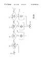
- the antenna system 5for transmitting and receiving data between a base station antenna 6 and a receiving apparatus 14 .
- the antenna system 5includes a digital repeater 10 connected between a link antenna 8 and a broadcast antenna 12 .
- the digital repeater 10extends the coverage area of the originating base station antenna 6 and/or fills nulls in the coverage area of the originating base station antenna 6 .
- the digital repeater 10transmits and receives RF signals to and from the receiving apparatus 14 , as shown in FIG. 2 .
- the receiving apparatus 14can comprise a pager, a TV or radio receiver, a cellular or PCS telephone, etc.
- the repeater 10operates in both a transmit mode and a receive mode.
- the link antenna 8is used to receive an incoming RF signal from the base station (BS) antenna 6 or from another repeater 10 .
- the illustrated repeater 10would therefore usually operate in the frequency band of the incoming RF signal or signals to be received.
- the broadcast antenna 12is used in the broadcast/repeat mode to transmit (and receive) a signal(s) to the receiving apparatus 14 , or to transmit a signal(s) to a further repeater 10 in a system using multiple repeaters 10 to broadcast or distribute an RF signal(s).
- the repeater 10operates in full duplex mode (i.e., operates in two directions simultaneously) using two separate frequencies, one for each direction.
- the digital repeater 10includes a forward path 16 (downlink path) and a reverse path 18 (uplink path).
- the repeater 10provides two-way communication with one or more receiving apparatus 14 .
- the forward path 16communicates an RF signal(s); from the BS antenna 6 to the receiving apparatus 14 while the reverse path communicates an RF signal(s) from the receiving apparatus 14 to the BS antenna 6 .
- a diplexer 100is connected between the input of the forward path 16 and the output of the reverse path 18 .
- a second diplexer 200is connected between the output of the forward path 16 and the input of the reverse path 18 .
- the diplexers 100 , 200are used to separate the power for each path 16 , 18 and to prevent noise wrap around from the forward path 16 to the reverse path 18 , and vice-versa.
- RF signals 19are received on the link antenna 8 and routed through the diplexer 100 and through the forward path 16 .
- the second diplexer 200then delivers filtered signals 43 to the broadcast antenna 12 which transmits the processed signals.
- the broadcast antenna 12receives RF signals 52 which are fed through the diplexer 200 and through the reverse path 18 .
- the first diplexer 100then delivers filtered signals 82 to the link antenna 8 which transmits the processed signals.
- the digital repeater 10is a multichannel repeater which can process multiple channels simultaneously in each path 16 , 18 . Therefore, the RF signals, such as the RF signals 19 , 52 , each contain one or more signals each at a different frequency (channel).
- the diplexer 100acts as a band pass filter adapted to receive the incoming RF signals 19 and only pass filtered signals 21 within a first specific band of frequencies.
- the first specific band of frequenciesare between about 1850 MHz and 1865 MHz; 1870 MHz and 1885 MHz; and/or 1890 MHz and 1905 MHz.
- the diplexer 100also allows one port to be a common connection for incoming downlink signals and outgoing uplink signals.
- the diplexers 100 and 200determine which operating frequency band(s) will be accepted by the repeater 10 .
- a PCS 1900 MHz repeaterwould operate in one of three bands: sub-band A, sub-band B or sub-band C.
- the operating frequencies for these bandsare as follows:
- Band Uplink Input Frequency Downlink Output Frequency Afrom 1850 to 1865 MHz from 1930 to 1945 MHz B from 1870 to 1885 MHz from 1950 to 196 5MHz C from 1890 to 1905 MHz from 1970 to 1985 MHz
- the diplexer 100serves to separate low power downlink input signals 19 from high power uplink output signals 82 .
- the power level of the outgoing uplink signal (filtered signal 82 )is typically several Watts while the power level of the incoming downlink signal (RF signal 19 ) is typically in the micro-Watt to milli-Watt range.
- the diplexer 100isolates the downlink path from the high power uplink path.
- the forward path 16also includes a low noise amplifier 110 for amplifying the filtered signals 21 and producing amplified signals 22 .
- the low noise amplifier 110is a wideband RF device whose input must be isolated from high power uplink signals.
- the diplexer 100isolates the low noise amplifier 110 from those high power uplink signals that can prevent proper operation of the repeater 10 .
- the low noise amplifier 110sets the repeater noise figure in the downlink direction.
- the noise figureis related to the noise factor, which is the signal-to-noise ratio (S/N) at the input of the repeater 10 divided by the S/N at the output of the repeater 10 .
- the noise figure10 *Log 10 (noise factor).
- a first RF down converter 120is included for down converting the amplified signals 22 .
- the RF down converter 120receives the amplified signals 22 .
- the amplified signals 22are combined by a mixer 24 with a local oscillator (LO) signal 34 to produce intermediate frequency (IF) signals 30 .
- LOlocal oscillator
- the IFis between about 10 MHz to 30 MHz, depending on the application.
- the LO signal 34is 1860 MHz and the amplified signals 22 are 1850 MHz
- the IF signalswould be 10 MHz.
- the IF signals 30are amplified by an amplifier 33 and filtered by a band pass filter 35 .
- the band pass filter 35significantly reduces the complex components or images of the amplified signal 22 and the LO signal 34 .
- the IF signals 30each contain one or more signals each at a different frequency (channel). All of the downlink channels pass through the first RF down converter 120 .
- the amplifiers used in the repeater 10comprise relatively low power, linear integrated circuit chip components, such as monolithic microwave integrated circuit (MMIC) chips. These chips may comprise chips made by the Gallium Arsenide (GaAs) heterojunction transistor manufacturing process. However, silicon process chips or CMOS process chips might also be utilized.
- MMICmonolithic microwave integrated circuit
- MMIC power amplifier chipsSome examples of MMIC power amplifier chips are as follows:
- RF MicrodevicesPCS linear power amplifier RF 2125P, RF 2125, RF 2126 or RF 2146, RF Micro Devices, Inc., 7625 Thorndike Road, Greensboro, N.C. 27409, or 7341-D W. Friendly Ave., Greensboro, N.C. 27410;
- Pacific Monolithics PM 2112 single supply RF IC power amplifierPacific Monolithics, Inc., 1308 Moffett Park Drive, Sunnyvale, Calif.;
- the forward path 16further includes a first multichannel Digital Signal Processor (DSP) module 130 which includes an analog-to-digital converter 420 which converts the incoming wideband IF signals 30 into digital signals 32 , as shown in FIG. 3 .
- the DSP moduleis a four channel DSP; however, one or more DSPs each capable of processing one or more channels could alternatively be used.
- the digital signals 32contain one or more channels. A first channel of the digital signals 32 is then digitally processed by the first digital down converter 500 . Similarly, the other channels of the digital signals 32 are digitally processed by the respective digital down converters 560 , 570 and 580 .
- the first channelis digitally down converted to a baseband center frequency around 0 Hz and applied to a series of software configurable low pass filters and gain stages, as described in detail below in relation to FIG. 3 .
- the processed channelis then digitally up converted back to the original IF frequency.
- the four processed signals from the four channelsare then digitally added together to form one digital signal 36 (having one or more channels of information, each channel having a different frequency).
- the digital signal 36is then applied to a digital-to-analog converter 700 .
- the DSP module 130outputs second IF signals 38 .
- an RF up converter 140is included for up converting the second IF signals 38 .
- the up converter 140converts the second IF signals 38 to second RF signals 42 , as shown in FIG. 5 a.
- the second IF signals 38are filtered by a band pass filter 44 and amplified by an amplifier 46 .
- the amplified signalsare then combined by a mixer 48 with a local oscillator (LO) signal 50 to produce the second RF signals 42 .
- the filter 44significantly reduces the complex components or images of the IF signals 38 and is the LO signal 50 .
- the IF signals 38each contain one or more signals each at a different frequency (channel). In one embodiment, the IF is between about 10 MHz to 30 MHz, depending on the application. Thus, where the LO signal 50 is 1860 MHz and the IF is 10 MHz, then the second RF signals 42 would be 1850 MHz. All of the uplink channels pass through the up converter 140 .
- a power amplifier 150is included for amplifying the second RF signals 42 into an amplified signal 51 which is at the desired output level.
- the linearity of the power amplifier 150determines the upper limit of the dynamic range of the repeater 10 .
- the output of the power amplifier 150is isolated from the reverse path 18 by the second diplexer 200 which is connected between the output of the forward path 16 and the input of the reverse path 18 .
- the diplexer 200acts as a band pass filter adapted to only pass outgoing filtered signals 43 within the first specific band of frequencies.
- the first specific band of frequenciesare between about 1850 MHz and 1865 MHz; 1870 MHz and 1885 MHz; and/or 1890 MHz and 1905 MHz.
- the filtered signals 43are sent to the broadcast antenna 12 and transmitted to the receiving apparatus 14 .
- the diplexer 200also acts as a band pass filter adapted to only pass incoming filtered signals 54 within a second specific band of frequencies.
- the second specific band of frequenciesare between about 1930 MHz and 1945 MHz; 1950 MHz and 1965 MHz; 1970 MHz and 1985 MHz.
- the diplexer 200allows one port to be a common connection for outgoing downlink signals 43 and incoming uplink signals 52 .
- the diplexers 100 and 200determine which operating frequency band(s) will be accepted by the repeater 10 .
- a PCS 1900 MHz repeaterwould operate in one of three bands: sub-band A, sub-band B or sub-band C.
- the operating frequencies for each bandare as follows:
- the diplexer 200serves to separate low power uplink input signals from high power downlink output signals.
- the power level of the outgoing downlink signal (filtered signal 43 )is typically several Watts while the power level of the incoming uplink signal (RF signal 52 ) is typically in the micro-Watt to milli-Watt range.
- the diplexer 200isolates the uplink path from the high power downlink signals.
- the reverse path 18also includes a low noise amplifier 210 for amplifying the filtered signals 54 and producing amplified signals 56 .
- the low noise amplifier 210sets the repeater noise figure in the uplink path 18 .
- the low noise amplifier 210is a wideband RF device whose input must be isolated from high power downlink signals that can prevent proper operation of the repeater 10 .
- the diplexer 200isolates the low noise amplifier 210 from those high power downlink signals.
- a second RF down converter 220is included for down converting the amplified signals 56 .
- the RF down converter 220receives the amplified signals 56 .
- the amplified signals 56are combined by a mixer 58 with a local oscillator (LO) signal 64 to produce intermediate frequency (IF) signals 65 .
- the IFis between about 10 MHz to 30 MHz, depending on the application. Thus, where the LO signal 64 is 1940 MHz and the amplified signals 56 are 1930 MHz, then the IF signals would be 10 MHz.
- the IF signals 65are amplified by an amplifier 62 and filtered by a band pass filter 63 .
- the band pass filter 63significantly reduces the complex components or images of the amplified signals 56 and the LO signal 64 . All of the uplink channels pass through the second RF down converter 220 .
- the reverse path 18further comprises a second multichannel DSP module 230 which operates in the same manner as the DSP module 130 .
- the incoming wideband IF signals 65 from the second RF down converter 220are sampled by the analog-to-digital converter 420 and separated into digital signals 32 , as shown in FIG. 3 .
- the DSP moduleis a four channel DSP; however, one or more DSPs each capable of processing one or more channels could alternatively be used.
- a first channel of the digital signals 32is then digitally processed by the first digital down converter 500 .
- the other channels of the digital signals 32are digitally processed by the respective digital down converters 560 , 570 and 580 .
- the first channelis digitally down converted to a baseband center frequency around 0 Hz and applied to a series of software configurable low pass filters and gain stages, as described in detail below in relation to FIG. 3 .
- the processed channelis then digitally up converted back to the original IF frequency.
- the multiple processed signals from each channelare then digitally added together to form one digital signal 36 (having one or more channels of information, each channel having a different frequency).
- the digital signal 36is then applied to a digital-to-analog converter 700 .
- the DSP module 230outputs fourth IF signals 70 , as shown in FIG. 2 .
- a second RF up converter 240is included for up converting the fourth IF signals 70 .
- the up converter 240converts the fourth IF signals 70 to fourth RF signals 72 , as shown in FIG. 5 b .
- the fourth IF signals 70are filtered by a band pass filter 74 and amplified by an amplifier 76 .
- the amplified signalsare then combined by a mixer 78 with a local oscillator (LO) signal 80 to produce the fourth RF signals 72 .
- the IFis between about 10 MHz to 30 MHz, depending on the application. Thus, where the LO signal 80 is 1940 MHz and the IF is 10 MHz, then the second RF signals 72 would be 1930 MHz.
- the band pass filter 74significantly reduces the complex components or images of the amplified signal 70 and the LO signal 80 . All of the uplink channels of the repeater pass through the up converter 240 .
- a second power amplifier 250is included for amplifying the fourth RF signals 72 into amplified signals 81 which are at the desired output level.
- the linearity of the power amplifier 250determines the upper limit of the dynamic range of the repeater 10 .
- the output of the power amplifier 250is isolated from the forward path 16 by the first diplexer 100 which is connected between the output of the reverse path 18 and the input of the forward path 16 .
- the diplexer 100acts as a band pass filter adapted to receive the amplified signals 81 and only pass outgoing filtered signals 82 within the second specific band of frequencies.
- the second specific band of frequenciesare between about 1930 MHz and 1945 MHz; 1950 MHz and 1965 MHz; and/or 1970 MHz and 1985 MHz.
- the filtered signals 82are sent to the link antenna 8 and transmitted to the BS antenna 6 .
- a synthesizer/clock 300is included for generating the LO signals 34 , 50 , 64 , and 80 for the RF down converters 120 , 220 and the RF up converters 140 , 240 .
- the RF down converter 120 and the RF up converter 140use the same LO frequency; thus, the LO signals 34 , 50 must be sufficiently isolated from each other to prevent cross-talk between the RF down converter 120 and the RF up converter 140 .
- the second RF down converter 220 and the second RF up converter 240also use the same LO frequency; thus the LO signals 64 , 80 must be sufficiently isolated from each other to prevent cross-talk between the second RF down converter 220 and the second RF up converter 240 . Therefore, the synthesizer/clock 300 provides LO signals that are sufficiently isolated from each other to prevent cross-talk between the forward and reverse paths 16 , 18 . The synthesizer/clock 300 also generates the sampling clock f clk for the analog-to-digital converter 420 , the DSP modules 130 , 230 and the digital-to-analog converter 700 .
- a user interface 310is provided for interacting with the DSP modules 130 , 230 .
- the user interface 310allows the DSP modules 130 , 230 to be programmed to adjust and configure certain parameters, as described below in connection with FIG. 3.
- a power supply 320converts the primary alternating current (AC) power to direct current (DC) power.
- the DSP module 130is a four channel DSP capable of processing four channels simultaneously; however, one or more DSPs each capable of processing one or more channels could alternatively be used.
- An adjustable attenuator 400is provided to accommodate a variety of IF signal levels.
- An impedance transformer 410converts the low impedance output of the attenuator 400 to a high impedance output suitable for the input of the analog-to-digital converter 420 .
- a feedback signal 84causes the attenuation to increase, thereby reducing the signal level present at the input of the impedance transformer 410 .
- the analog-to-digital converter 420converts the incoming wideband IF signals 30 to the digital signals 32 which are sampled at a rate determined by f clk In one embodiment, the approximate value of f clk is 60 MHz depending on the application.
- a digital down converter 500is provided. Because each of the channels operate in the same manner, only the digital down converter 500 is described and illustrated in detail.
- the digital down converter 500includes a numerically controlled oscillator (NCO) 510 .
- the frequency of the NCO 510determines which channel of the digital signals 32 is processed, i.e., it determines the center frequency around which the digital down converter 500 is tuned.
- the NCO 510can be tuned (through the user interface 310 ) to discrete frequencies with a separation of less than, e.g., 1 Hz. In one embodiment, the useable frequency range of the NCO 510 is 0 Hz to approximately 0.4*f clk .
- the NCO 510produces two LO signals at the same output frequency, an in-phase version 86 and a quadrature version 88 which is shifted 90 degrees (to produce a 1 ⁇ 4 cycle delay) with respect to the in-phase version 86 .
- the output frequency and the phase of the LO signalsare programmable via the user interface 310 .
- a pair of digital mixers 520down convert the frequency of the specified channel of the digital signals 32 to a frequency determined by the NCO 510 .
- the output of the mixersare centered around 0 Hz.
- One of the mixersuses the in-phase version 86 of the LO signal from the NCO 510 .
- This mixerconverts the specified channel into an in-phase, down converted digital signal 90 centered around 0 Hz.
- the second one of the mixersuses the quadrature version 88 of the LO signal from the NCO 510 .
- This mixerconverts the specified channel into a quadrature, down converted digital signal 91 centered around 0 Hz.
- the rate of samples produced by each mixeris equal to the original sample rate, f clk .
- a digital decimator 530includes a digital low pass filter.
- the digital decimator 530discards samples of the down converted digital signals 90 , 91 that are not needed. This is possible because the signal of interest is centered around 0 Hz and occupies a narrow bandwidth.
- the decimation rateis a measure of the number of samples discarded. As the decimation rate increases, the bandwidth of the undiscarded samples decreases.
- the decimation rateis programmable via the user interface 310 .
- the digital low pass filteris a Finite Impulse Response (FIR) type filter with programmable coefficients that define the shape of the filter. The filter coefficients are also programmable via the user interface 310 .
- FIRFinite Impulse Response
- the digital down converter 500further includes a two channel digital amplifier 540 .
- One channel of the digital amplifier 540amplifies the in-phase, down converted digital signal 90 and a second channel amplifies the quadrature, down converted digital signal 91 .
- Both channels of the digital amplifier 540are set to the same gain.
- the digital amplifier 540has a gain range of 0 to 28 dB in steps of approximately 0.1 dB. The amount of gain is programmable via the user interface 310 . Thus, a user can control the coverage area of the repeater 10 by adjusting the gain of the digital amplifier 540 .
- a digital multiplexer 550is included for converting the in-phase, down converted digital signal 90 and the quadrature, down converted digital signal 91 from the output of the digital amplifier 540 into one multiplexed signal 92 having the in-phase and quadrature samples interleaved.
- Digital down converters 560 , 570 , and 580 of the DSP module 130operate in the same manner as the above described digital down converter 500 .
- a digital up converter 600is also provided. Because each of the channels operate in the same manner, only the digital up converter 600 is described and illustrated in detail.
- the digital up converter 600includes a digital demultiplexer 610 which converts the multiplexed signal 92 from the digital down converter 500 into separate in-phase and quadrature signals 93 , 94 .
- a digital interpolator 620includes a digital low pass filter.
- the digital low pass filteris a FIR type filter with programmable coefficients. These coefficients define the shape of the filter.
- the filter coefficientsare programmable via the user interface 310 .
- the digital interpolator 620generates data samples that are needed in order to increase the sample rate to the original f clk frequency.
- the interpolation rateis a measure of how many samples are generated. Generally, the interpolation rate is equal to the decimation rate used for the digital decimator 530 .
- the interpolation rateis also programmable via the user interface 310 .
- the digital up converter 600further includes a numerically controlled oscillator (NCO) 630 .
- the frequency of the NCO 630determines the frequency at which the up converter is tuned. This item can be tuned to discrete frequencies with a separation of less than 1 Hz. In one embodiment, the useable frequency range of the NCO 630 is 0 Hz to approximately 0.4*f clk .
- the NCO 630like the NCO 510 , produces two LO signals at the same output frequency, an in-phase version 95 and a quadrature version 96 which is shifted 90 degrees (to produce a 1 ⁇ 4 cycle delay) with respect to the in-phase version 95 .
- the output frequency and the phase of the LO signalsare programmable via the user interface 310 .
- a pair of digital mixers 640up convert the frequency of the separate signals 93 , 94 centered at 0 Hz to the frequency programmed into the NCO 630 .
- One of the mixersuses the in-phase version 95 of the LO signal from the NCO 630 .
- This mixerconverts the separate signal 93 into an in-phase, up converted digital signal 97 centered around the IF.
- the second one of the mixersuses the quadrature version 96 of the LO signal from is the NCO 630 .
- This mixerconverts the separate signal 94 into a quadrature, up converted digital signal 98 centered around the IF.
- the rate of samples produced by each mixeris once again equal to the original sample rate, f clk .
- a digital adder 650is included for algebraically adding the in-phase, up converted digital signal 97 and the quadrature, up converted digital signal 98 to produce a first output signal 99 a .
- Channels 660 , 670 , and 680 of the digital up converter 600operate in the same manner as the above described digital up converter channel. In one embodiment, the channels 660 , 670 , and 680 produce output signals 99 b , 99 c , and 99 d , respectively.
- a multichannel digital adder 690is included.
- the digital adder 690algebraically adds the digital output signals, e.g., 99 a - 99 d , and applies a programmable scale factor (from 0 to 1) to the sum of the output signals 99 a - 99 d .
- the scale factorprevents the summed channels from overflowing. For example, where there are four channels and each channel processes 16-bit words, the sum of the four 16-bit words could be greater than 16 bits. Therefore, the sum is scaled to prevent an overflow situation.
- the digital scale factoris programmable via the user interface 310 .
- the digital-to-analog converter 700converts the sum of the output signals, e.g., 99 a - 99 d , to a differential analog signal 37 .
- a differential signalis a signal with a magnitude equal to the difference between the voltage potentials at two ports.
- a balanced to unbalanced signal transformer 710is provided for converting the differential analog signal 37 to a single, low impedance analog output signal (the second IF signals 38 of FIG. 2 ). This single output signal uses ground (0 volts) as its reference.
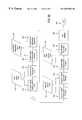
- a microprocessor 800controls the digital down converter 500 and the digital up converter 600 .
- the microprocessor 800provides the multichannel DSP module 130 with programming data and reports the status of the module 130 .
- the microprocessor 800interacts with the user interface 310 to allow a user to program and configure the DSP module 130 to set, e.g., the gain of the digital signal processors, the frequency and phase of the in-phase and the quadrature versions of the first digital signal, the rate at which the first digital signal is decimated, the amplification of the digital signal to control the coverage area of the digital repeater, the rate at which the separate signals are interpolated, and the digital scale factor.
- the microprocessor 800begins executing the program in block 900 .
- the microprocessor 800then monitors the user interface 310 to determine whether a new channel setup is desired by a user (block 902 ). If a no is indicated, the microprocessor 800 returns to block 900 . Otherwise, if a yes is indicated, the microprocessor 800 determines whether the new channel requested by the user is installed on the DSP module, i.e., is the channel available (block 904 ).
- the DSP modulemay have, for example, between 1 and 16 available channels.
- the microprocessor 800reports an allocation error in block 906 and the program ends (block 908 ). Otherwise, if the requested channel is installed and available, the microprocessor 800 determines whether the entered frequency is a valid frequency, i.e., whether the frequency is available (block 910 ). For example, the valid center frequencies may be multiples of 5 kHz. Therefore, if a frequency of 27 kHz were selected, this frequency would not be available. If the frequency is not available, the microprocessor 800 reports a frequency error in block 912 and the program ends (block 908 ). Otherwise, the microprocessor 800 determines in block 914 whether the modulation format corresponding to the new channel is available.
- the microprocessor 800If the modulation format is not available, the microprocessor 800 reports a format error in block 916 and the program ends (block 908 ). Otherwise, the microprocessor 800 programs the digital down converter NCO 510 (block 918 ) and the digital up converter NCO 630 (block 920 ) by using data from the NCO look-up table (block 922 ).
- the microprocessor 800programs the digital down converter decimator 530 (block 924 ) and the digital up converter interpolator 620 (block 926 ) by using data from the decimator/interpolator look-up table (block 928 ).
- the microprocessor 800next programs the digital down converter FIR filter 530 (block 930 ) and the digital up converter FIR filter 620 (block 932 ) by using data from the FIR filter look-up table (block 934 ).
- the microprocessor 800then programs the digital down converter amplifier 540 (block 936 ) and the digital up converter scale factor 690 (block 938 ) by using data from the gain/scale look-up table (block 940 ).
- the microprocessor 800proceeds to flush the registers (block 942 ) and the program ends (block 944 ). During the period of time when a user is programming the DSP module, no data is being written to the data registers. Once the programming routine of FIGS. 6 a and 6 b is completed, the registers are flushed to clear any old data contained therein. Then, the repeater begins operating using the newly programmed parameters and only new data is processed, the old data having been flushed from the data “pipeline.”
- the BS antenna 6could be replaced with one or more repeater systems each including a link antenna 8 , a digital repeater 10 , and a broadcast antenna 12 .
- repeater systemscan be daisy-chained together to extend the range of an originating base station antenna.
- the digital repeater 10 described aboveoperates independent of the frequency band being processed. That is, the repeater 10 may be used in any frequency band, including, but not limited to, the following:
- GSMGlobal System for Mobile communications
- LMDS26 GHz band
- LMDS26 GHz band
- Bluetooth Applications(2400 MHz band)—(Bluetooth is the name of a wireless protocol standard, created by Ericsson)
- the present inventionprovides a digital repeater 10 that includes a pair of digital signal processors, one for each path, that are software configurable such that a user can program and configure certain parameters. These parameters include, e.g., the gain of the digital signal processors, the frequency and phase of the in-phase and the quadrature versions of the first digital signal, the rate at which the first digital signal is decimated, the amplification of the digital signal to control the coverage area of the digital repeater, the rate at which the separate signals are interpolated, and the digital scale factor.
- the digital repeater 10is capable of transmitting and receiving multiple channels using only a single RF down converter/RF up converter pair for each path.
- the digital repeater 10provides greater channel resolution which allows more channels to be placed closer together. This is accomplished by using precise digital filters that have less than a 1 kHz frequency difference between the 15 dB and 40 dB points.
- the digital repeater 10can process multiple modulation formats without changing the repeater hardware; instead, the digital signal processors are programmable such that changing the modulation format is quick and easy.
- the digital repeater 10is programmable to match the modulation format used by many communications networks.
- the digital repeater 10can even automatically detect the modulation format used by a particular network and change the bandwidth of the filters based on the modulation format detected.
- the digital repeater 10provides virtually identical filter performance despite impedance mismatches.
Landscapes
- Engineering & Computer Science (AREA)
- Computer Networks & Wireless Communication (AREA)
- Signal Processing (AREA)
- Radio Relay Systems (AREA)
- Transceivers (AREA)
Abstract
Description
| Band | Uplink Input Frequency | Downlink Output Frequency |
| A | from 1850 to 1865 MHz | from 1930 to 1945 MHz |
| B | from 1870 to 1885 MHz | from 1950 to 196 5MHz |
| C | from 1890 to 1905 MHz | from 1970 to 1985 MHz |
| Band | Downlink Input Frequency | Uplink Output Frequency |
| A | from 1930 to 1945 MHz | from 1850 to 1865 MHz |
| B | from 1950 to 1965 MHz | from 1870 to 1885 MHz |
| C | from 1970 to 1985 MHz | from 1890 to 1905 MHz |
Claims (58)
Priority Applications (6)
| Application Number | Priority Date | Filing Date | Title |
|---|---|---|---|
| US09/460,023US6697603B1 (en) | 1999-12-13 | 1999-12-13 | Digital repeater |
| EP00126543AEP1109332A3 (en) | 1999-12-13 | 2000-12-11 | A digital repeater |
| KR1020000076049AKR100808890B1 (en) | 1999-12-13 | 2000-12-13 | A digital repeater |
| BR0005870-0ABR0005870A (en) | 1999-12-13 | 2000-12-13 | Digital Repeater |
| CNB001349597ACN1302628C (en) | 1999-12-13 | 2000-12-13 | Digital transponder |
| KR1020070142054AKR100808899B1 (en) | 1999-12-13 | 2007-09-04 | A digital repeater |
Applications Claiming Priority (1)
| Application Number | Priority Date | Filing Date | Title |
|---|---|---|---|
| US09/460,023US6697603B1 (en) | 1999-12-13 | 1999-12-13 | Digital repeater |
Publications (1)
| Publication Number | Publication Date |
|---|---|
| US6697603B1true US6697603B1 (en) | 2004-02-24 |
Family
ID=23827109
Family Applications (1)
| Application Number | Title | Priority Date | Filing Date |
|---|---|---|---|
| US09/460,023Expired - LifetimeUS6697603B1 (en) | 1999-12-13 | 1999-12-13 | Digital repeater |
Country Status (5)
| Country | Link |
|---|---|
| US (1) | US6697603B1 (en) |
| EP (1) | EP1109332A3 (en) |
| KR (2) | KR100808890B1 (en) |
| CN (1) | CN1302628C (en) |
| BR (1) | BR0005870A (en) |
Cited By (153)
| Publication number | Priority date | Publication date | Assignee | Title |
|---|---|---|---|---|
| US20020022452A1 (en)* | 2000-08-10 | 2002-02-21 | Ken-Ichi Toya | Land mobile satellite-communication system |
| US20020034958A1 (en)* | 2000-06-05 | 2002-03-21 | Gerald Oberschmidt | Indoor wireless system using active reflector |
| US20020037027A1 (en)* | 2000-07-31 | 2002-03-28 | Medlock Joel D. | Apparatus and methods for sample selection and reuse of rake fingers in spread spectrum systems |
| US20020037060A1 (en)* | 2000-08-17 | 2002-03-28 | Samsung Electronics Co., Ltd. | Digital down-converter and receiver |
| US20020039383A1 (en)* | 2000-06-16 | 2002-04-04 | Oki Techno Centre Pte Ltd. | Methods and apparatus for reducing signal degradation |
| US20020048325A1 (en)* | 2000-09-21 | 2002-04-25 | Samsung Electronics Co., Ltd. | Digital down-converter |
| US20030112895A1 (en)* | 1998-10-21 | 2003-06-19 | Parkervision, Inc. | Intergrated frequency translation and selectivity |
| US20030143971A1 (en)* | 2000-08-22 | 2003-07-31 | Toyohiko Hongo | Radio transmitting/receiving device |
| US20030171107A1 (en)* | 1999-12-22 | 2003-09-11 | Sorrells David F. | Differential frequency down-conversion using techniques of universal frequency translation technology |
| US20030181186A1 (en)* | 1999-04-16 | 2003-09-25 | Sorrells David F. | Reducing DC offsets using spectral spreading |
| US20030185163A1 (en)* | 2002-03-27 | 2003-10-02 | Bertonis James G. | System and method for wireless cable data transmission |
| US6798351B1 (en) | 1998-10-21 | 2004-09-28 | Parkervision, Inc. | Automated meter reader applications of universal frequency translation |
| US6836650B2 (en) | 1998-10-21 | 2004-12-28 | Parkervision, Inc. | Methods and systems for down-converting electromagnetic signals, and applications thereof |
| US6853690B1 (en) | 1999-04-16 | 2005-02-08 | Parkervision, Inc. | Method, system and apparatus for balanced frequency up-conversion of a baseband signal and 4-phase receiver and transceiver embodiments |
| US20050058091A1 (en)* | 2002-01-10 | 2005-03-17 | Rudd Clarence Charles | Method for extending communications protocols over a distance |
| US6873836B1 (en) | 1999-03-03 | 2005-03-29 | Parkervision, Inc. | Universal platform module and methods and apparatuses relating thereto enabled by universal frequency translation technology |
| US20050215193A1 (en)* | 2001-11-12 | 2005-09-29 | Thomas Kummetz | Digital repeater having bandpass filtering, adaptive pre-equalization and suppression of natural oscillation |
| US20050232223A1 (en)* | 2004-04-20 | 2005-10-20 | Nokia Corporation | Use of signaling for auto-configuration of modulators and repeaters |
| US6975848B2 (en) | 2002-06-04 | 2005-12-13 | Parkervision, Inc. | Method and apparatus for DC offset removal in a radio frequency communication channel |
| US20060003697A1 (en)* | 2004-07-05 | 2006-01-05 | Ntt Docomo, Inc. | Repeating station, a communication apparatus, and a directivity control method |
| US20060019603A1 (en)* | 2004-07-22 | 2006-01-26 | Frank Pergal | Wireless repeater with arbitrary programmable selectivity |
| US7006805B1 (en) | 1999-01-22 | 2006-02-28 | Parker Vision, Inc. | Aliasing communication system with multi-mode and multi-band functionality and embodiments thereof, such as the family radio service |
| US7010559B2 (en) | 2000-11-14 | 2006-03-07 | Parkervision, Inc. | Method and apparatus for a parallel correlator and applications thereof |
| US7010286B2 (en) | 2000-04-14 | 2006-03-07 | Parkervision, Inc. | Apparatus, system, and method for down-converting and up-converting electromagnetic signals |
| US20060063487A1 (en)* | 2004-09-07 | 2006-03-23 | Samsung Electronics Co., Ltd. | Wireless repeater using cross-polarized signals to reduce feedback in an FDD wireless network |
| US7027786B1 (en) | 1998-10-21 | 2006-04-11 | Parkervision, Inc. | Carrier and clock recovery using universal frequency translation |
| US7039372B1 (en) | 1998-10-21 | 2006-05-02 | Parkervision, Inc. | Method and system for frequency up-conversion with modulation embodiments |
| US7047385B1 (en)* | 2003-06-16 | 2006-05-16 | Cisco Technology, Inc. | High-speed memory for use in networking systems |
| US20060104384A1 (en)* | 2004-10-22 | 2006-05-18 | Sorrells David F | Systems and methods for vector power amplification |
| US7050508B2 (en) | 1998-10-21 | 2006-05-23 | Parkervision, Inc. | Method and system for frequency up-conversion with a variety of transmitter configurations |
| US7054296B1 (en) | 1999-08-04 | 2006-05-30 | Parkervision, Inc. | Wireless local area network (WLAN) technology and applications including techniques of universal frequency translation |
| US7065162B1 (en) | 1999-04-16 | 2006-06-20 | Parkervision, Inc. | Method and system for down-converting an electromagnetic signal, and transforms for same |
| US7072427B2 (en) | 2001-11-09 | 2006-07-04 | Parkervision, Inc. | Method and apparatus for reducing DC offsets in a communication system |
| US7082171B1 (en) | 1999-11-24 | 2006-07-25 | Parkervision, Inc. | Phase shifting applications of universal frequency translation |
| US7085335B2 (en) | 2001-11-09 | 2006-08-01 | Parkervision, Inc. | Method and apparatus for reducing DC offsets in a communication system |
| US7110435B1 (en) | 1999-03-15 | 2006-09-19 | Parkervision, Inc. | Spread spectrum applications of universal frequency translation |
| US7110444B1 (en) | 1999-08-04 | 2006-09-19 | Parkervision, Inc. | Wireless local area network (WLAN) using universal frequency translation technology including multi-phase embodiments and circuit implementations |
| US20060215598A1 (en)* | 2005-03-28 | 2006-09-28 | Lucent Technologies, Inc. | Wireless communication system facilitating communications through local networks |
| US20060217102A1 (en)* | 2005-03-22 | 2006-09-28 | Yinon Degani | Cellular/Wi-Fi combination devices |
| US7209725B1 (en) | 1999-01-22 | 2007-04-24 | Parkervision, Inc | Analog zero if FM decoder and embodiments thereof, such as the family radio service |
| US20070090874A1 (en)* | 2004-10-22 | 2007-04-26 | Parkervision, Inc. | RF power transmission, modulation, and amplification embodiments |
| US7236754B2 (en) | 1999-08-23 | 2007-06-26 | Parkervision, Inc. | Method and system for frequency up-conversion |
| KR100764166B1 (en) | 2006-04-18 | 2007-10-12 | 포스데이타 주식회사 | Repeater interface unit and signal conversion method |
| US20070249301A1 (en)* | 2006-04-24 | 2007-10-25 | Parkervision, Inc. | Systems and methods of RF power transmission, modulation, and amplification, including architectural embodiments of same |
| US20070249283A1 (en)* | 2006-04-21 | 2007-10-25 | Richard Neil Braithwaite | System and method for estimation and compensation of radiated feedback coupling in a high gain repeater |
| US20070249300A1 (en)* | 2006-04-24 | 2007-10-25 | Sorrells David F | Systems and methods of RF tower transmission, modulation, and amplification, including embodiments for compensating for waveform distortion |
| US7292835B2 (en) | 2000-01-28 | 2007-11-06 | Parkervision, Inc. | Wireless and wired cable modem applications of universal frequency translation technology |
| US20070264009A1 (en)* | 2006-04-28 | 2007-11-15 | Adc Telecommunications, Inc. | Systems and methods of optical path protection for distributed antenna systems |
| US7299005B1 (en)* | 2004-01-07 | 2007-11-20 | Sprint Spectrum L.P. | Radio frequency repeater with automated block/channel selection |
| US7308242B2 (en) | 1998-10-21 | 2007-12-11 | Parkervision, Inc. | Method and system for down-converting and up-converting an electromagnetic signal, and transforms for same |
| US7321640B2 (en) | 2002-06-07 | 2008-01-22 | Parkervision, Inc. | Active polyphase inverter filter for quadrature signal generation |
| US7327696B1 (en)* | 2000-09-11 | 2008-02-05 | Yahoo! Inc. | Intelligent voice converter |
| US7379883B2 (en) | 2002-07-18 | 2008-05-27 | Parkervision, Inc. | Networking methods and systems |
| US20080143885A1 (en)* | 2006-12-14 | 2008-06-19 | Analog Devices, Inc. | Television upconverter structures |
| US20080225929A1 (en)* | 2007-03-02 | 2008-09-18 | Qualcomm Incorporated | Closed Form Calculation of Temporal Equalizer Weights Used in a Repeater Transmitter Leakage Cancellation System |
| US7454453B2 (en) | 2000-11-14 | 2008-11-18 | Parkervision, Inc. | Methods, systems, and computer program products for parallel correlation and applications thereof |
| US7460584B2 (en) | 2002-07-18 | 2008-12-02 | Parkervision, Inc. | Networking methods and systems |
| US20080298509A1 (en)* | 2007-01-16 | 2008-12-04 | Parkervision, Inc. | RF Power Transmission, Modulation, and Amplification, Including Embodiments for Generating Vector Modulation Control Signals |
| US20080315946A1 (en)* | 2007-06-19 | 2008-12-25 | Rawlins Gregory S | Combiner-Less Multiple Input Single Output (MISO) Amplification with Blended Control |
| US7480485B1 (en) | 2004-01-07 | 2009-01-20 | Sprint Spectrum L.P. | Radio frequency repeater with automated block/channel selection |
| US20090046616A1 (en)* | 2007-08-14 | 2009-02-19 | Canam Technology Incorporated | System and method for inserting break-in signals in communication systems |
| US20090072898A1 (en)* | 2007-06-19 | 2009-03-19 | Sorrells David F | Systems and Methods of RF Power Transmission, Modulation, and Amplification, Including Blended Control Embodiments |
| US7515896B1 (en) | 1998-10-21 | 2009-04-07 | Parkervision, Inc. | Method and system for down-converting an electromagnetic signal, and transforms for same, and aperture relationships |
| US20090091384A1 (en)* | 2007-06-28 | 2009-04-09 | Sorrells David F | Systems and methods of RF power transmission, modulation and amplification |
| US7554508B2 (en) | 2000-06-09 | 2009-06-30 | Parker Vision, Inc. | Phased array antenna applications on universal frequency translation |
| US20090196215A1 (en)* | 2008-01-31 | 2009-08-06 | John Sabat | Wireless repeater with smart uplink |
| US20090231170A1 (en)* | 2006-03-30 | 2009-09-17 | Posdata Co., Ltd | Apparatus and method for digital frequency down-conversion |
| US20090247213A1 (en)* | 2008-03-27 | 2009-10-01 | Ahmadreza Rofougaran | Method and system for frequency-shift based chip-to-chip communications |
| US20090247109A1 (en)* | 2008-03-28 | 2009-10-01 | Ahmadreza Rofougaran | Method and system for communicating via a frequency shifting repeater |
| US20090280768A1 (en)* | 2008-05-07 | 2009-11-12 | Ahmadreza Rofougaran | Method And System For Inter IC Communications Utilizing A Spatial Multi-Link Repeater |
| US20090278596A1 (en)* | 2008-05-07 | 2009-11-12 | Ahmadreza Rofougaran | Method And System For Communicating Via A Spatial Multilink Repeater |
| US20090279593A1 (en)* | 2008-05-07 | 2009-11-12 | Ahmadreza Rofougaran | Method And System For Inter-PCB Communication Utilizing A Spatial Multi-Link Repeater |
| US7623866B1 (en) | 2006-07-10 | 2009-11-24 | Sprint Spectrum L.P. | Automatic generation of neighbor lists in a wireless network |
| US20090298433A1 (en)* | 2005-10-24 | 2009-12-03 | Sorrells David F | Systems and Methods of RF Power Transmission, Modulation, and Amplification |
| KR100932279B1 (en) | 2007-12-11 | 2009-12-16 | 한국전자통신연구원 | Repeater and its signal processing method and frequency conversion method |
| US20090318086A1 (en)* | 2008-06-19 | 2009-12-24 | Ahmadreza Rofougaran | Method and system for frequency-shift based pcb-to-pcb communications |
| US20090316829A1 (en)* | 2008-06-19 | 2009-12-24 | Ahmadreza Rofougaran | Method and system for transmit diversity for chip-to-chip communications |
| US7639982B2 (en)* | 2000-07-19 | 2009-12-29 | Adc Telecommunications, Inc. | Point-to-multipoint digital radio frequency transport |
| US7693230B2 (en) | 1999-04-16 | 2010-04-06 | Parkervision, Inc. | Apparatus and method of differential IQ frequency up-conversion |
| US20100159859A1 (en)* | 2008-12-24 | 2010-06-24 | Ahmadreza Rofougaran | Method and system for frequency control in a frequency shifting repeater |
| US20100167684A1 (en)* | 2001-01-12 | 2010-07-01 | Silicon Laboratories Inc. | Quadrature signal generation in radio-frequency apparatus and associated methods |
| US20100201884A1 (en)* | 2009-02-12 | 2010-08-12 | Yoshihiro Ashizaki | Display unit |
| US7817958B2 (en) | 2006-12-22 | 2010-10-19 | Lgc Wireless Inc. | System for and method of providing remote coverage area for wireless communications |
| US7844273B2 (en) | 2006-07-14 | 2010-11-30 | Lgc Wireless, Inc. | System for and method of for providing dedicated capacity in a cellular network |
| US7848758B1 (en) | 2005-09-27 | 2010-12-07 | Sprint Spectrum L.P. | Dynamic allocation of carrier frequencies in wireless wide area networks |
| US7848770B2 (en) | 2006-08-29 | 2010-12-07 | Lgc Wireless, Inc. | Distributed antenna communications system and methods of implementing thereof |
| US20110111710A1 (en)* | 2009-11-11 | 2011-05-12 | Nokia Corporation | Methods and Apparatuses for Frequency Filtering for Non-Centered Component Carrier Transmission |
| US20110143658A1 (en)* | 2009-12-11 | 2011-06-16 | Van Hanson | System and method for determining and controlling gain margin in an rf repeater |
| US8005050B2 (en) | 2007-03-23 | 2011-08-23 | Lgc Wireless, Inc. | Localization of a mobile device in distributed antenna communications system |
| US8010116B2 (en) | 2007-06-26 | 2011-08-30 | Lgc Wireless, Inc. | Distributed antenna communications system |
| US8295406B1 (en)* | 1999-08-04 | 2012-10-23 | Parkervision, Inc. | Universal platform module for a plurality of communication protocols |
| US8315336B2 (en) | 2007-05-18 | 2012-11-20 | Parkervision, Inc. | Systems and methods of RF power transmission, modulation, and amplification, including a switching stage embodiment |
| US8320313B1 (en) | 2009-06-19 | 2012-11-27 | Sprint Spectrum L.P. | Method and system for carrier frequency management based on slot contention |
| US8325648B1 (en) | 2009-04-29 | 2012-12-04 | Sprint Spectrum L.P. | Methods and systems for assigning a wireless communication device to a carrier frequency |
| US8391195B1 (en)* | 2010-08-23 | 2013-03-05 | Sprint Communications Company L.P. | Assisted transport of communications for wireless communication devices |
| US8498241B1 (en) | 2009-03-10 | 2013-07-30 | Sprint Spectrum L.P. | Use of macro-network channel-list messages for selection of carriers for low-cost internet base-station frequency-hopping pilot beacons |
| US20130208680A1 (en)* | 2011-12-06 | 2013-08-15 | Advanced Rf Technologies, Inc. | Method for setting a filter coefficient for a communication system |
| US8559869B2 (en)* | 2011-09-21 | 2013-10-15 | Daniel R. Ash, JR. | Smart channel selective repeater |
| US8583100B2 (en) | 2007-01-25 | 2013-11-12 | Adc Telecommunications, Inc. | Distributed remote base station system |
| US8605604B1 (en)* | 2009-12-23 | 2013-12-10 | Marvell International Ltd. | WLAN module test system |
| US8737454B2 (en) | 2007-01-25 | 2014-05-27 | Adc Telecommunications, Inc. | Modular wireless communications platform |
| US8755454B2 (en) | 2011-06-02 | 2014-06-17 | Parkervision, Inc. | Antenna control |
| US8787429B2 (en) | 2012-06-19 | 2014-07-22 | Andrew Llc | Communication system with channel compensating equalizer |
| US8798013B1 (en) | 2011-03-25 | 2014-08-05 | Sprint Spectrum L.P. | Method and system for management of data transmission in timeslots |
| US8908607B2 (en) | 2012-10-31 | 2014-12-09 | Andrew Llc | Digital baseband transport in telecommunications distribution systems |
| US8958789B2 (en) | 2002-12-03 | 2015-02-17 | Adc Telecommunications, Inc. | Distributed digital antenna system |
| US9001811B2 (en) | 2009-05-19 | 2015-04-07 | Adc Telecommunications, Inc. | Method of inserting CDMA beacon pilots in output of distributed remote antenna nodes |
| US9037143B2 (en) | 2010-08-16 | 2015-05-19 | Corning Optical Communications LLC | Remote antenna clusters and related systems, components, and methods supporting digital data signal propagation between remote antenna units |
| US9042732B2 (en) | 2010-05-02 | 2015-05-26 | Corning Optical Communications LLC | Providing digital data services in optical fiber-based distributed radio frequency (RF) communication systems, and related components and methods |
| US9107148B1 (en) | 2009-11-30 | 2015-08-11 | Sprint Spectrum L.P. | Use of pre-handoff macro-carrier data for prioritization of carriers in femtocell frequency-hopping pilot beacons |
| US9112547B2 (en) | 2007-08-31 | 2015-08-18 | Adc Telecommunications, Inc. | System for and method of configuring distributed antenna communications system |
| US9219879B2 (en) | 2009-11-13 | 2015-12-22 | Corning Optical Communications LLC | Radio-over-fiber (ROF) system for protocol-independent wired and/or wireless communication |
| US9240835B2 (en) | 2011-04-29 | 2016-01-19 | Corning Optical Communications LLC | Systems, methods, and devices for increasing radio frequency (RF) power in distributed antenna systems |
| US9253003B1 (en) | 2014-09-25 | 2016-02-02 | Corning Optical Communications Wireless Ltd | Frequency shifting a communications signal(S) in a multi-frequency distributed antenna system (DAS) to avoid or reduce frequency interference |
| US9258052B2 (en) | 2012-03-30 | 2016-02-09 | Corning Optical Communications LLC | Reducing location-dependent interference in distributed antenna systems operating in multiple-input, multiple-output (MIMO) configuration, and related components, systems, and methods |
| US9319138B2 (en) | 2010-02-15 | 2016-04-19 | Corning Optical Communications LLC | Dynamic cell bonding (DCB) for radio-over-fiber (RoF)-based networks and communication systems and related methods |
| US9325429B2 (en) | 2011-02-21 | 2016-04-26 | Corning Optical Communications LLC | Providing digital data services as electrical signals and radio-frequency (RF) communications over optical fiber in distributed communications systems, and related components and methods |
| US9338823B2 (en) | 2012-03-23 | 2016-05-10 | Corning Optical Communications Wireless Ltd | Radio-frequency integrated circuit (RFIC) chip(s) for providing distributed antenna system functionalities, and related components, systems, and methods |
| US9407383B2 (en) | 2014-12-23 | 2016-08-02 | Ibiquity Digital Corporation | Apparatus and method for distributing content from an HD radio system |
| US9420542B2 (en) | 2014-09-25 | 2016-08-16 | Corning Optical Communications Wireless Ltd | System-wide uplink band gain control in a distributed antenna system (DAS), based on per band gain control of remote uplink paths in remote units |
| US9450653B2 (en) | 2010-10-19 | 2016-09-20 | Commscope Technologies Llc | Systems and methods for transporting digital RF signals |
| US9450598B2 (en)* | 2015-01-26 | 2016-09-20 | Guzik Technical Enterprises | Two-stage digital down-conversion of RF pulses |
| US9455784B2 (en) | 2012-10-31 | 2016-09-27 | Corning Optical Communications Wireless Ltd | Deployable wireless infrastructures and methods of deploying wireless infrastructures |
| US9525488B2 (en) | 2010-05-02 | 2016-12-20 | Corning Optical Communications LLC | Digital data services and/or power distribution in optical fiber-based distributed communications systems providing digital data and radio frequency (RF) communications services, and related components and methods |
| US9525472B2 (en) | 2014-07-30 | 2016-12-20 | Corning Incorporated | Reducing location-dependent destructive interference in distributed antenna systems (DASS) operating in multiple-input, multiple-output (MIMO) configuration, and related components, systems, and methods |
| US9531452B2 (en) | 2012-11-29 | 2016-12-27 | Corning Optical Communications LLC | Hybrid intra-cell / inter-cell remote unit antenna bonding in multiple-input, multiple-output (MIMO) distributed antenna systems (DASs) |
| US9608677B2 (en) | 2005-10-24 | 2017-03-28 | Parker Vision, Inc | Systems and methods of RF power transmission, modulation, and amplification |
| US9729267B2 (en) | 2014-12-11 | 2017-08-08 | Corning Optical Communications Wireless Ltd | Multiplexing two separate optical links with the same wavelength using asymmetric combining and splitting |
| US9730228B2 (en) | 2014-08-29 | 2017-08-08 | Corning Optical Communications Wireless Ltd | Individualized gain control of remote uplink band paths in a remote unit in a distributed antenna system (DAS), based on combined uplink power level in the remote unit |
| US9775123B2 (en) | 2014-03-28 | 2017-09-26 | Corning Optical Communications Wireless Ltd. | Individualized gain control of uplink paths in remote units in a distributed antenna system (DAS) based on individual remote unit contribution to combined uplink power |
| US9813229B2 (en) | 2007-10-22 | 2017-11-07 | Corning Optical Communications Wireless Ltd | Communication system using low bandwidth wires |
| US9820171B2 (en) | 2010-09-14 | 2017-11-14 | Dali Wireless, Inc. | Remotely reconfigurable distributed antenna system and methods |
| US9826410B2 (en) | 2009-04-29 | 2017-11-21 | Commscope Technologies Llc | Distributed antenna system for wireless network systems |
| US9867052B2 (en) | 2000-03-27 | 2018-01-09 | Commscope Technologies Llc | Multiprotocol antenna system for multiple service providers |
| US20180191397A1 (en)* | 2015-05-01 | 2018-07-05 | Andrew Wireless Systems Gmbh | Non-duplexer architectures for telecommunications system |
| US10080178B2 (en) | 2006-12-26 | 2018-09-18 | Dali Wireless, Inc. | Distributed antenna system |
| US10096909B2 (en) | 2014-11-03 | 2018-10-09 | Corning Optical Communications Wireless Ltd. | Multi-band monopole planar antennas configured to facilitate improved radio frequency (RF) isolation in multiple-input multiple-output (MIMO) antenna arrangement |
| US10110308B2 (en) | 2014-12-18 | 2018-10-23 | Corning Optical Communications Wireless Ltd | Digital interface modules (DIMs) for flexibly distributing digital and/or analog communications signals in wide-area analog distributed antenna systems (DASs) |
| US10128951B2 (en) | 2009-02-03 | 2018-11-13 | Corning Optical Communications LLC | Optical fiber-based distributed antenna systems, components, and related methods for monitoring and configuring thereof |
| US10135533B2 (en) | 2014-11-13 | 2018-11-20 | Corning Optical Communications Wireless Ltd | Analog distributed antenna systems (DASS) supporting distribution of digital communications signals interfaced from a digital signal source and analog radio frequency (RF) communications signals |
| US10187151B2 (en) | 2014-12-18 | 2019-01-22 | Corning Optical Communications Wireless Ltd | Digital-analog interface modules (DAIMs) for flexibly distributing digital and/or analog communications signals in wide-area analog distributed antenna systems (DASs) |
| US10278131B2 (en) | 2013-09-17 | 2019-04-30 | Parkervision, Inc. | Method, apparatus and system for rendering an information bearing function of time |
| US10499269B2 (en) | 2015-11-12 | 2019-12-03 | Commscope Technologies Llc | Systems and methods for assigning controlled nodes to channel interfaces of a controller |
| US10577130B1 (en)* | 2016-12-07 | 2020-03-03 | Space Systems/Loral, Llc | Flexible radio frequency converters for digital payloads |
| US10659163B2 (en) | 2014-09-25 | 2020-05-19 | Corning Optical Communications LLC | Supporting analog remote antenna units (RAUs) in digital distributed antenna systems (DASs) using analog RAU digital adaptors |
| US11057130B2 (en) | 2017-01-02 | 2021-07-06 | Mojoose, Inc. | Automatic signal strength indicator and automatic antenna switch |
| US11159129B2 (en) | 2002-05-01 | 2021-10-26 | Dali Wireless, Inc. | Power amplifier time-delay invariant predistortion methods and apparatus |
| US11178609B2 (en) | 2010-10-13 | 2021-11-16 | Corning Optical Communications LLC | Power management for remote antenna units in distributed antenna systems |
| US20220045742A1 (en)* | 2020-08-04 | 2022-02-10 | Qualcomm Incorporated | Techniques for forwarding a wireless signal using a digital repeater |
| US11297603B2 (en) | 2010-08-17 | 2022-04-05 | Dali Wireless, Inc. | Neutral host architecture for a distributed antenna system |
| US11418155B2 (en) | 2002-05-01 | 2022-08-16 | Dali Wireless, Inc. | Digital hybrid mode power amplifier system |
| US20220283293A1 (en)* | 2020-02-10 | 2022-09-08 | Perceptive Inc. | Centralized object detection sensor network system |
| RU2840230C1 (en)* | 2024-04-27 | 2025-05-19 | Федеральное государственное бюджетное образовательное учреждение высшего образования "Поволжский государственный университет телекоммуникаций и информатики" | Ultra high frequency identification signal repeater |
Families Citing this family (18)
| Publication number | Priority date | Publication date | Assignee | Title |
|---|---|---|---|---|
| KR100613908B1 (en) | 2004-05-12 | 2006-08-22 | 한국전자통신연구원 | Apparatus and Method for Corresponding Frequency Synchronization in On-channel Repeater |
| JP3930521B2 (en)* | 2005-08-04 | 2007-06-13 | 日本無線株式会社 | Digital television broadcast signal relay device |
| CN101110625B (en)* | 2006-07-21 | 2011-03-02 | 中兴通讯股份有限公司 | Double antenna wireless digital relay unit and its operating procedure |
| CN101192870B (en)* | 2006-11-20 | 2011-08-24 | 中兴通讯股份有限公司 | A relay system for mobile communication |
| DE102008028732A1 (en)* | 2008-06-17 | 2009-12-24 | Andrew Wireless Systems Gmbh | repeater |
| US8135339B2 (en) | 2008-12-31 | 2012-03-13 | Andrew Llc | System and method for feedback cancellation in repeaters |
| EP2802090B1 (en) | 2013-05-07 | 2019-07-31 | Andrew Wireless Systems GmbH | Digital repeater device |
| EP3829079B1 (en) | 2013-06-25 | 2022-11-02 | Andrew Wireless Systems GmbH | Method in a repeater system |
| EP3823185B1 (en) | 2014-04-08 | 2025-09-24 | Outdoor Wireless Networks LLC | Digital repeater system |
| US20160049966A1 (en)* | 2014-08-15 | 2016-02-18 | Aviacomm Inc. | Rfic architecture for multi-stream remote radio head application |
| EP2991441A3 (en)* | 2014-08-27 | 2016-04-06 | Fraunhofer-Gesellschaft zur Förderung der angewandten Forschung e.V. | A transceiver, a sudac, a method for signal processing in a transceiver, and methods for signal processing in a sudac |
| US9780863B2 (en) | 2014-11-07 | 2017-10-03 | Nextivity, Inc. | System and method for selecting an operator to boost in a repeater |
| EP3091668A1 (en)* | 2015-05-05 | 2016-11-09 | CommScope Technologies LLC | Receiver arrangement for use in a digital repeater system |
| EP3331173B1 (en)* | 2016-11-30 | 2019-10-30 | Deutsche Telekom AG | Assembly for expanding the range of mimo radio systems to shaded areas |
| CN109639322B (en)* | 2019-01-30 | 2021-07-23 | 北京慧通微电科技有限公司 | Power line carrier communication system based on digital-analog combined frequency division and full duplex method |
| US11832276B2 (en)* | 2020-08-04 | 2023-11-28 | Qualcomm Incorporated | Techniques for communicating using a relay node |
| EP4277158A1 (en) | 2022-05-09 | 2023-11-15 | Unitron NV | A mobile telecommunication signal booster |
| CN116744501A (en)* | 2023-03-13 | 2023-09-12 | 杰华特微电子股份有限公司 | Lighting control circuit, lighting control method, and lighting circuit |
Citations (6)
| Publication number | Priority date | Publication date | Assignee | Title |
|---|---|---|---|---|
| US5535240A (en)* | 1993-10-29 | 1996-07-09 | Airnet Communications Corporation | Transceiver apparatus employing wideband FFT channelizer and inverse FFT combiner for multichannel communication network |
| US6118810A (en)* | 1997-05-08 | 2000-09-12 | Ericsson, Inc. | Multi-channel base station/terminal design covering complete system frequency range |
| US6167099A (en)* | 1994-12-29 | 2000-12-26 | Motorola, Inc. | Multi-channel digital transceiver and method |
| US6253060B1 (en)* | 1996-12-20 | 2001-06-26 | Airnet Communications Corporation | Method and apparatus employing wireless remote loopback capability for a wireless system repeater to provide end-to-end testing without a wireline connection |
| US6370185B1 (en)* | 1999-08-10 | 2002-04-09 | Airnet Communications Corporation | Translating repeater system with improved backhaul efficiency |
| US6389078B1 (en)* | 1997-11-03 | 2002-05-14 | Harris Corporation | Configurable circuits for field programmable radio frequency communications equipment and methods therefor |
Family Cites Families (5)
| Publication number | Priority date | Publication date | Assignee | Title |
|---|---|---|---|---|
| GB8809602D0 (en)* | 1988-04-22 | 1988-05-25 | British Telecomm | Mobile radio systems |
| US5404570A (en)* | 1992-11-23 | 1995-04-04 | Telefonaktiebolaget L M Ericsson | Radio coverage in closed environments |
| SE502811C2 (en)* | 1994-05-11 | 1996-01-22 | Allgon Ab | Repeater |
| KR0133336B1 (en)* | 1994-12-21 | 1998-04-21 | 양승택 | Radio frequency signal automatic level control device for satellite repeater and method |
| KR19990081412A (en)* | 1998-04-29 | 1999-11-15 | 유태로 | Optical conversion repeater and optical signal transmission method using single optical cable |
- 1999
- 1999-12-13USUS09/460,023patent/US6697603B1/ennot_activeExpired - Lifetime
- 2000
- 2000-12-11EPEP00126543Apatent/EP1109332A3/ennot_activeWithdrawn
- 2000-12-13KRKR1020000076049Apatent/KR100808890B1/ennot_activeExpired - Lifetime
- 2000-12-13BRBR0005870-0Apatent/BR0005870A/ennot_activeApplication Discontinuation
- 2000-12-13CNCNB001349597Apatent/CN1302628C/ennot_activeExpired - Lifetime
- 2007
- 2007-09-04KRKR1020070142054Apatent/KR100808899B1/ennot_activeExpired - Lifetime
Patent Citations (6)
| Publication number | Priority date | Publication date | Assignee | Title |
|---|---|---|---|---|
| US5535240A (en)* | 1993-10-29 | 1996-07-09 | Airnet Communications Corporation | Transceiver apparatus employing wideband FFT channelizer and inverse FFT combiner for multichannel communication network |
| US6167099A (en)* | 1994-12-29 | 2000-12-26 | Motorola, Inc. | Multi-channel digital transceiver and method |
| US6253060B1 (en)* | 1996-12-20 | 2001-06-26 | Airnet Communications Corporation | Method and apparatus employing wireless remote loopback capability for a wireless system repeater to provide end-to-end testing without a wireline connection |
| US6118810A (en)* | 1997-05-08 | 2000-09-12 | Ericsson, Inc. | Multi-channel base station/terminal design covering complete system frequency range |
| US6389078B1 (en)* | 1997-11-03 | 2002-05-14 | Harris Corporation | Configurable circuits for field programmable radio frequency communications equipment and methods therefor |
| US6370185B1 (en)* | 1999-08-10 | 2002-04-09 | Airnet Communications Corporation | Translating repeater system with improved backhaul efficiency |
Cited By (419)
| Publication number | Priority date | Publication date | Assignee | Title |
|---|---|---|---|---|
| US7218907B2 (en) | 1998-10-21 | 2007-05-15 | Parkervision, Inc. | Method and circuit for down-converting a signal |
| US7194246B2 (en) | 1998-10-21 | 2007-03-20 | Parkervision, Inc. | Methods and systems for down-converting a signal using a complementary transistor structure |
| US7620378B2 (en) | 1998-10-21 | 2009-11-17 | Parkervision, Inc. | Method and system for frequency up-conversion with modulation embodiments |
| US7937059B2 (en) | 1998-10-21 | 2011-05-03 | Parkervision, Inc. | Converting an electromagnetic signal via sub-sampling |
| US8019291B2 (en) | 1998-10-21 | 2011-09-13 | Parkervision, Inc. | Method and system for frequency down-conversion and frequency up-conversion |
| US8160534B2 (en) | 1998-10-21 | 2012-04-17 | Parkervision, Inc. | Applications of universal frequency translation |
| US20030112895A1 (en)* | 1998-10-21 | 2003-06-19 | Parkervision, Inc. | Intergrated frequency translation and selectivity |
| US7376410B2 (en) | 1998-10-21 | 2008-05-20 | Parkervision, Inc. | Methods and systems for down-converting a signal using a complementary transistor structure |
| US8190116B2 (en) | 1998-10-21 | 2012-05-29 | Parker Vision, Inc. | Methods and systems for down-converting a signal using a complementary transistor structure |
| US8190108B2 (en) | 1998-10-21 | 2012-05-29 | Parkervision, Inc. | Method and system for frequency up-conversion |
| US7076011B2 (en) | 1998-10-21 | 2006-07-11 | Parkervision, Inc. | Integrated frequency translation and selectivity |
| US7245886B2 (en) | 1998-10-21 | 2007-07-17 | Parkervision, Inc. | Method and system for frequency up-conversion with modulation embodiments |
| US6798351B1 (en) | 1998-10-21 | 2004-09-28 | Parkervision, Inc. | Automated meter reader applications of universal frequency translation |
| US6836650B2 (en) | 1998-10-21 | 2004-12-28 | Parkervision, Inc. | Methods and systems for down-converting electromagnetic signals, and applications thereof |
| US7936022B2 (en) | 1998-10-21 | 2011-05-03 | Parkervision, Inc. | Method and circuit for down-converting a signal |
| US7050508B2 (en) | 1998-10-21 | 2006-05-23 | Parkervision, Inc. | Method and system for frequency up-conversion with a variety of transmitter configurations |
| US7027786B1 (en) | 1998-10-21 | 2006-04-11 | Parkervision, Inc. | Carrier and clock recovery using universal frequency translation |
| US7515896B1 (en) | 1998-10-21 | 2009-04-07 | Parkervision, Inc. | Method and system for down-converting an electromagnetic signal, and transforms for same, and aperture relationships |
| US8233855B2 (en) | 1998-10-21 | 2012-07-31 | Parkervision, Inc. | Up-conversion based on gated information signal |
| US7308242B2 (en) | 1998-10-21 | 2007-12-11 | Parkervision, Inc. | Method and system for down-converting and up-converting an electromagnetic signal, and transforms for same |
| US7389100B2 (en) | 1998-10-21 | 2008-06-17 | Parkervision, Inc. | Method and circuit for down-converting a signal |
| US8340618B2 (en) | 1998-10-21 | 2012-12-25 | Parkervision, Inc. | Method and system for down-converting an electromagnetic signal, and transforms for same, and aperture relationships |
| US7865177B2 (en) | 1998-10-21 | 2011-01-04 | Parkervision, Inc. | Method and system for down-converting an electromagnetic signal, and transforms for same, and aperture relationships |
| US7826817B2 (en) | 1998-10-21 | 2010-11-02 | Parker Vision, Inc. | Applications of universal frequency translation |
| US7697916B2 (en) | 1998-10-21 | 2010-04-13 | Parkervision, Inc. | Applications of universal frequency translation |
| US7529522B2 (en) | 1998-10-21 | 2009-05-05 | Parkervision, Inc. | Apparatus and method for communicating an input signal in polar representation |
| US7693502B2 (en) | 1998-10-21 | 2010-04-06 | Parkervision, Inc. | Method and system for down-converting an electromagnetic signal, transforms for same, and aperture relationships |
| US7016663B2 (en) | 1998-10-21 | 2006-03-21 | Parkervision, Inc. | Applications of universal frequency translation |
| US7039372B1 (en) | 1998-10-21 | 2006-05-02 | Parkervision, Inc. | Method and system for frequency up-conversion with modulation embodiments |
| US7006805B1 (en) | 1999-01-22 | 2006-02-28 | Parker Vision, Inc. | Aliasing communication system with multi-mode and multi-band functionality and embodiments thereof, such as the family radio service |
| US7209725B1 (en) | 1999-01-22 | 2007-04-24 | Parkervision, Inc | Analog zero if FM decoder and embodiments thereof, such as the family radio service |
| US7483686B2 (en) | 1999-03-03 | 2009-01-27 | Parkervision, Inc. | Universal platform module and methods and apparatuses relating thereto enabled by universal frequency translation technology |
| US6873836B1 (en) | 1999-03-03 | 2005-03-29 | Parkervision, Inc. | Universal platform module and methods and apparatuses relating thereto enabled by universal frequency translation technology |
| US7110435B1 (en) | 1999-03-15 | 2006-09-19 | Parkervision, Inc. | Spread spectrum applications of universal frequency translation |
| US7599421B2 (en) | 1999-03-15 | 2009-10-06 | Parkervision, Inc. | Spread spectrum applications of universal frequency translation |
| US8223898B2 (en) | 1999-04-16 | 2012-07-17 | Parkervision, Inc. | Method and system for down-converting an electromagnetic signal, and transforms for same |
| US7539474B2 (en) | 1999-04-16 | 2009-05-26 | Parkervision, Inc. | DC offset, re-radiation, and I/Q solutions using universal frequency translation technology |
| US7065162B1 (en) | 1999-04-16 | 2006-06-20 | Parkervision, Inc. | Method and system for down-converting an electromagnetic signal, and transforms for same |
| US6879817B1 (en) | 1999-04-16 | 2005-04-12 | Parkervision, Inc. | DC offset, re-radiation, and I/Q solutions using universal frequency translation technology |
| US7929638B2 (en) | 1999-04-16 | 2011-04-19 | Parkervision, Inc. | Wireless local area network (WLAN) using universal frequency translation technology including multi-phase embodiments |
| US7693230B2 (en) | 1999-04-16 | 2010-04-06 | Parkervision, Inc. | Apparatus and method of differential IQ frequency up-conversion |
| US7321751B2 (en) | 1999-04-16 | 2008-01-22 | Parkervision, Inc. | Method and apparatus for improving dynamic range in a communication system |
| US7724845B2 (en) | 1999-04-16 | 2010-05-25 | Parkervision, Inc. | Method and system for down-converting and electromagnetic signal, and transforms for same |
| US7773688B2 (en) | 1999-04-16 | 2010-08-10 | Parkervision, Inc. | Method, system, and apparatus for balanced frequency up-conversion, including circuitry to directly couple the outputs of multiple transistors |
| US8036304B2 (en) | 1999-04-16 | 2011-10-11 | Parkervision, Inc. | Apparatus and method of differential IQ frequency up-conversion |
| US8077797B2 (en) | 1999-04-16 | 2011-12-13 | Parkervision, Inc. | Method, system, and apparatus for balanced frequency up-conversion of a baseband signal |
| US8224281B2 (en) | 1999-04-16 | 2012-07-17 | Parkervision, Inc. | Down-conversion of an electromagnetic signal with feedback control |
| US7894789B2 (en) | 1999-04-16 | 2011-02-22 | Parkervision, Inc. | Down-conversion of an electromagnetic signal with feedback control |
| US8229023B2 (en) | 1999-04-16 | 2012-07-24 | Parkervision, Inc. | Wireless local area network (WLAN) using universal frequency translation technology including multi-phase embodiments |
| US7272164B2 (en) | 1999-04-16 | 2007-09-18 | Parkervision, Inc. | Reducing DC offsets using spectral spreading |
| US20030181186A1 (en)* | 1999-04-16 | 2003-09-25 | Sorrells David F. | Reducing DC offsets using spectral spreading |
| US20040002321A1 (en)* | 1999-04-16 | 2004-01-01 | Parker Vision, Inc. | Method and apparatus for reducing re-radiation using techniques of universal frequency translation technology |
| US7224749B2 (en) | 1999-04-16 | 2007-05-29 | Parkervision, Inc. | Method and apparatus for reducing re-radiation using techniques of universal frequency translation technology |
| US7190941B2 (en) | 1999-04-16 | 2007-03-13 | Parkervision, Inc. | Method and apparatus for reducing DC offsets in communication systems using universal frequency translation technology |
| US8594228B2 (en) | 1999-04-16 | 2013-11-26 | Parkervision, Inc. | Apparatus and method of differential IQ frequency up-conversion |
| US6853690B1 (en) | 1999-04-16 | 2005-02-08 | Parkervision, Inc. | Method, system and apparatus for balanced frequency up-conversion of a baseband signal and 4-phase receiver and transceiver embodiments |
| US7110444B1 (en) | 1999-08-04 | 2006-09-19 | Parkervision, Inc. | Wireless local area network (WLAN) using universal frequency translation technology including multi-phase embodiments and circuit implementations |
| US8295406B1 (en)* | 1999-08-04 | 2012-10-23 | Parkervision, Inc. | Universal platform module for a plurality of communication protocols |
| US7653145B2 (en) | 1999-08-04 | 2010-01-26 | Parkervision, Inc. | Wireless local area network (WLAN) using universal frequency translation technology including multi-phase embodiments and circuit implementations |
| US7054296B1 (en) | 1999-08-04 | 2006-05-30 | Parkervision, Inc. | Wireless local area network (WLAN) technology and applications including techniques of universal frequency translation |
| US7546096B2 (en) | 1999-08-23 | 2009-06-09 | Parkervision, Inc. | Frequency up-conversion using a harmonic generation and extraction module |
| US20070224950A1 (en)* | 1999-08-23 | 2007-09-27 | Parkervision, Inc. | Method and system for frequency up-conversion |
| US7236754B2 (en) | 1999-08-23 | 2007-06-26 | Parkervision, Inc. | Method and system for frequency up-conversion |
| US7082171B1 (en) | 1999-11-24 | 2006-07-25 | Parkervision, Inc. | Phase shifting applications of universal frequency translation |
| US7379515B2 (en) | 1999-11-24 | 2008-05-27 | Parkervision, Inc. | Phased array antenna applications of universal frequency translation |
| US6963734B2 (en) | 1999-12-22 | 2005-11-08 | Parkervision, Inc. | Differential frequency down-conversion using techniques of universal frequency translation technology |
| US20030171107A1 (en)* | 1999-12-22 | 2003-09-11 | Sorrells David F. | Differential frequency down-conversion using techniques of universal frequency translation technology |
| US7292835B2 (en) | 2000-01-28 | 2007-11-06 | Parkervision, Inc. | Wireless and wired cable modem applications of universal frequency translation technology |
| US9867052B2 (en) | 2000-03-27 | 2018-01-09 | Commscope Technologies Llc | Multiprotocol antenna system for multiple service providers |
| US10321328B2 (en) | 2000-03-27 | 2019-06-11 | Commscope Technologies Llc | Multiprotocol antenna system for multiple service providers |
| US7107028B2 (en) | 2000-04-14 | 2006-09-12 | Parkervision, Inc. | Apparatus, system, and method for up converting electromagnetic signals |
| US7496342B2 (en) | 2000-04-14 | 2009-02-24 | Parkervision, Inc. | Down-converting electromagnetic signals, including controlled discharge of capacitors |
| US8295800B2 (en) | 2000-04-14 | 2012-10-23 | Parkervision, Inc. | Apparatus and method for down-converting electromagnetic signals by controlled charging and discharging of a capacitor |
| US7218899B2 (en) | 2000-04-14 | 2007-05-15 | Parkervision, Inc. | Apparatus, system, and method for up-converting electromagnetic signals |
| US7822401B2 (en) | 2000-04-14 | 2010-10-26 | Parkervision, Inc. | Apparatus and method for down-converting electromagnetic signals by controlled charging and discharging of a capacitor |
| US7010286B2 (en) | 2000-04-14 | 2006-03-07 | Parkervision, Inc. | Apparatus, system, and method for down-converting and up-converting electromagnetic signals |
| US7386292B2 (en) | 2000-04-14 | 2008-06-10 | Parkervision, Inc. | Apparatus, system, and method for down-converting and up-converting electromagnetic signals |
| US20020034958A1 (en)* | 2000-06-05 | 2002-03-21 | Gerald Oberschmidt | Indoor wireless system using active reflector |
| US7554508B2 (en) | 2000-06-09 | 2009-06-30 | Parker Vision, Inc. | Phased array antenna applications on universal frequency translation |
| US7085314B2 (en)* | 2000-06-16 | 2006-08-01 | Oki Techno Centre (Singapore) Pte Ltd. | Methods and apparatus for reducing signal degradation |
| US20020039383A1 (en)* | 2000-06-16 | 2002-04-04 | Oki Techno Centre Pte Ltd. | Methods and apparatus for reducing signal degradation |
| US7639982B2 (en)* | 2000-07-19 | 2009-12-29 | Adc Telecommunications, Inc. | Point-to-multipoint digital radio frequency transport |
| US9332402B2 (en)* | 2000-07-19 | 2016-05-03 | Commscope Technologies Llc | Point-to-multipoint digital radio frequency transport |
| US10498434B2 (en) | 2000-07-19 | 2019-12-03 | CommScope Technolgies LLC | Point-to-multipoint digital radio frequency transport |
| US10505635B2 (en)* | 2000-07-19 | 2019-12-10 | Commscope Technologies Llc | Point-to-multipoint digital radio frequency transport |
| US8577286B2 (en) | 2000-07-19 | 2013-11-05 | Adc Telecommunications, Inc. | Point-to-multipoint digital radio frequency transport |
| US20140036758A1 (en)* | 2000-07-19 | 2014-02-06 | Adc Telecommunications, Inc. | Point-to-multipoint digital radio frequency transport |
| US7065128B2 (en)* | 2000-07-31 | 2006-06-20 | Infineon Technologies Ag | Apparatus and methods for sample selection and reuse of rake fingers in spread spectrum systems |
| US20020037027A1 (en)* | 2000-07-31 | 2002-03-28 | Medlock Joel D. | Apparatus and methods for sample selection and reuse of rake fingers in spread spectrum systems |
| US7616680B2 (en) | 2000-07-31 | 2009-11-10 | Infineon Technologies Ag | Method for processing data in a spread spectrum system |
| US20060291542A1 (en)* | 2000-07-31 | 2006-12-28 | Infineon Technologies Ag | Apparatus and methods for sample selection and reuse of rake fingers in spread spectrum systems |
| US7095980B2 (en)* | 2000-08-10 | 2006-08-22 | Honda Giken Kogyo Kabushiki Kaisha | Land mobile satellite-communication system |
| US20020022452A1 (en)* | 2000-08-10 | 2002-02-21 | Ken-Ichi Toya | Land mobile satellite-communication system |
| US20020037060A1 (en)* | 2000-08-17 | 2002-03-28 | Samsung Electronics Co., Ltd. | Digital down-converter and receiver |
| US7089032B2 (en)* | 2000-08-22 | 2006-08-08 | Renesas Technology Corporation | Radio transmitting/receiving device |
| US20030143971A1 (en)* | 2000-08-22 | 2003-07-31 | Toyohiko Hongo | Radio transmitting/receiving device |
| US7327696B1 (en)* | 2000-09-11 | 2008-02-05 | Yahoo! Inc. | Intelligent voice converter |
| US7127227B2 (en)* | 2000-09-21 | 2006-10-24 | Samsung Electronics Co., Ltd. | Digital down-converter |
| US20020048325A1 (en)* | 2000-09-21 | 2002-04-25 | Samsung Electronics Co., Ltd. | Digital down-converter |
| US7233969B2 (en) | 2000-11-14 | 2007-06-19 | Parkervision, Inc. | Method and apparatus for a parallel correlator and applications thereof |
| US7010559B2 (en) | 2000-11-14 | 2006-03-07 | Parkervision, Inc. | Method and apparatus for a parallel correlator and applications thereof |
| US7433910B2 (en) | 2000-11-14 | 2008-10-07 | Parkervision, Inc. | Method and apparatus for the parallel correlator and applications thereof |
| US7454453B2 (en) | 2000-11-14 | 2008-11-18 | Parkervision, Inc. | Methods, systems, and computer program products for parallel correlation and applications thereof |
| US7991815B2 (en) | 2000-11-14 | 2011-08-02 | Parkervision, Inc. | Methods, systems, and computer program products for parallel correlation and applications thereof |
| US8532236B2 (en)* | 2001-01-12 | 2013-09-10 | Silicon Laboratories Inc. | Quadrature signal generation in radio-frequency apparatus and associated methods |
| US20100167684A1 (en)* | 2001-01-12 | 2010-07-01 | Silicon Laboratories Inc. | Quadrature signal generation in radio-frequency apparatus and associated methods |
| US8446994B2 (en) | 2001-11-09 | 2013-05-21 | Parkervision, Inc. | Gain control in a communication channel |
| US7653158B2 (en) | 2001-11-09 | 2010-01-26 | Parkervision, Inc. | Gain control in a communication channel |
| US7072427B2 (en) | 2001-11-09 | 2006-07-04 | Parkervision, Inc. | Method and apparatus for reducing DC offsets in a communication system |
| US7085335B2 (en) | 2001-11-09 | 2006-08-01 | Parkervision, Inc. | Method and apparatus for reducing DC offsets in a communication system |
| US8625658B2 (en)* | 2001-11-12 | 2014-01-07 | Andrew Wireless Systems Gmbh | Digital repeater having bandpass filtering, adaptive pre-equalization and suppression of natural oscillation |
| US9203503B2 (en) | 2001-11-12 | 2015-12-01 | Andrew Wireless Systems Gmbh | Digital repeater having bandpass filtering, adaptive pre-equalization and suppression of natural oscillation |
| US9929793B2 (en)* | 2001-11-12 | 2018-03-27 | Andrew Wireless Systems Gmbh | Digital repeater having bandpass filtering, adaptive pre-equalization and suppressin of natural oscillation |
| US20110002367A1 (en)* | 2001-11-12 | 2011-01-06 | Andrew Llc | Digital repeater having bandpass filtering, adaptive pre-equalization and suppression of natural oscillation |
| US20050215193A1 (en)* | 2001-11-12 | 2005-09-29 | Thomas Kummetz | Digital repeater having bandpass filtering, adaptive pre-equalization and suppression of natural oscillation |
| US7809047B2 (en)* | 2001-11-12 | 2010-10-05 | Andrew Llc | Digital repeater having bandpass filtering, adaptive pre-equalization and suppression of natural oscillation |
| US20050058091A1 (en)* | 2002-01-10 | 2005-03-17 | Rudd Clarence Charles | Method for extending communications protocols over a distance |
| US7782809B2 (en)* | 2002-01-10 | 2010-08-24 | Thomson Licensing | Method for extending communications protocols over a distance |
| US20030185163A1 (en)* | 2002-03-27 | 2003-10-02 | Bertonis James G. | System and method for wireless cable data transmission |
| US11418155B2 (en) | 2002-05-01 | 2022-08-16 | Dali Wireless, Inc. | Digital hybrid mode power amplifier system |
| US11159129B2 (en) | 2002-05-01 | 2021-10-26 | Dali Wireless, Inc. | Power amplifier time-delay invariant predistortion methods and apparatus |
| US6975848B2 (en) | 2002-06-04 | 2005-12-13 | Parkervision, Inc. | Method and apparatus for DC offset removal in a radio frequency communication channel |
| US7321640B2 (en) | 2002-06-07 | 2008-01-22 | Parkervision, Inc. | Active polyphase inverter filter for quadrature signal generation |
| US7460584B2 (en) | 2002-07-18 | 2008-12-02 | Parkervision, Inc. | Networking methods and systems |
| US8407061B2 (en) | 2002-07-18 | 2013-03-26 | Parkervision, Inc. | Networking methods and systems |
| US7379883B2 (en) | 2002-07-18 | 2008-05-27 | Parkervision, Inc. | Networking methods and systems |
| US8160196B2 (en) | 2002-07-18 | 2012-04-17 | Parkervision, Inc. | Networking methods and systems |
| US8958789B2 (en) | 2002-12-03 | 2015-02-17 | Adc Telecommunications, Inc. | Distributed digital antenna system |
| USRE50112E1 (en) | 2002-12-03 | 2024-09-03 | Outdoor Wireless Networks LLC | Distributed digital antenna system |
| USRE49377E1 (en) | 2002-12-03 | 2023-01-17 | Commscope Technologies Llc | Distributed digital antenna system |
| US7047385B1 (en)* | 2003-06-16 | 2006-05-16 | Cisco Technology, Inc. | High-speed memory for use in networking systems |
| US7299005B1 (en)* | 2004-01-07 | 2007-11-20 | Sprint Spectrum L.P. | Radio frequency repeater with automated block/channel selection |
| US7480485B1 (en) | 2004-01-07 | 2009-01-20 | Sprint Spectrum L.P. | Radio frequency repeater with automated block/channel selection |
| US7626960B2 (en)* | 2004-04-20 | 2009-12-01 | Nokia Corporation | Use of signaling for auto-configuration of modulators and repeaters |
| US20050232223A1 (en)* | 2004-04-20 | 2005-10-20 | Nokia Corporation | Use of signaling for auto-configuration of modulators and repeaters |
| US20060003697A1 (en)* | 2004-07-05 | 2006-01-05 | Ntt Docomo, Inc. | Repeating station, a communication apparatus, and a directivity control method |
| US7606531B2 (en)* | 2004-07-05 | 2009-10-20 | Ntt Docomo, Inc. | Repeating station, a communication apparatus, and a directivity control method |
| US12096239B2 (en) | 2004-07-22 | 2024-09-17 | Strong Force Iot Portfolio 2016, Llc | Wireless repeater with arbitrary programmable selectivity |
| US20060019603A1 (en)* | 2004-07-22 | 2006-01-26 | Frank Pergal | Wireless repeater with arbitrary programmable selectivity |
| US10785660B2 (en) | 2004-07-22 | 2020-09-22 | Strong Force Iot Portfolio 2016, Llc | Wireless repeater with arbitrary programmable selectivity |
| US11057781B2 (en) | 2004-07-22 | 2021-07-06 | Strong Force Iot Portfolio 2016, Llc | Wireless repeater with arbitrary programmable selectivity |
| US7623826B2 (en) | 2004-07-22 | 2009-11-24 | Frank Pergal | Wireless repeater with arbitrary programmable selectivity |
| US7764925B2 (en)* | 2004-09-07 | 2010-07-27 | Samsung Electronics Co., Ltd. | Wireless repeater using cross-polarized signals to reduce feedback in an FDD wireless network |
| US20060063487A1 (en)* | 2004-09-07 | 2006-03-23 | Samsung Electronics Co., Ltd. | Wireless repeater using cross-polarized signals to reduce feedback in an FDD wireless network |
| US7526261B2 (en) | 2004-10-22 | 2009-04-28 | Parkervision, Inc. | RF power transmission, modulation, and amplification, including cartesian 4-branch embodiments |
| US8639196B2 (en) | 2004-10-22 | 2014-01-28 | Parkervision, Inc. | Control modules |
| US9197164B2 (en) | 2004-10-22 | 2015-11-24 | Parkervision, Inc. | RF power transmission, modulation, and amplification, including direct cartesian 2-branch embodiments |
| US8433264B2 (en) | 2004-10-22 | 2013-04-30 | Parkervision, Inc. | Multiple input single output (MISO) amplifier having multiple transistors whose output voltages substantially equal the amplifier output voltage |
| US8406711B2 (en) | 2004-10-22 | 2013-03-26 | Parkervision, Inc. | Systems and methods of RF power transmission, modulation, and amplification, including a Cartesian-Polar-Cartesian-Polar (CPCP) embodiment |
| US20060104384A1 (en)* | 2004-10-22 | 2006-05-18 | Sorrells David F | Systems and methods for vector power amplification |
| US9143088B2 (en) | 2004-10-22 | 2015-09-22 | Parkervision, Inc. | Control modules |
| US7639072B2 (en) | 2004-10-22 | 2009-12-29 | Parkervision, Inc. | Controlling a power amplifier to transition among amplifier operational classes according to at least an output signal waveform trajectory |
| US7647030B2 (en) | 2004-10-22 | 2010-01-12 | Parkervision, Inc. | Multiple input single output (MISO) amplifier with circuit branch output tracking |
| US8447248B2 (en) | 2004-10-22 | 2013-05-21 | Parkervision, Inc. | RF power transmission, modulation, and amplification, including power control of multiple input single output (MISO) amplifiers |
| US9197163B2 (en) | 2004-10-22 | 2015-11-24 | Parkvision, Inc. | Systems, and methods of RF power transmission, modulation, and amplification, including embodiments for output stage protection |
| US7672650B2 (en) | 2004-10-22 | 2010-03-02 | Parkervision, Inc. | Systems and methods of RF power transmission, modulation, and amplification, including multiple input single output (MISO) amplifier embodiments comprising harmonic control circuitry |
| US7945224B2 (en) | 2004-10-22 | 2011-05-17 | Parkervision, Inc. | Systems and methods of RF power transmission, modulation, and amplification, including waveform distortion compensation embodiments |
| US8428527B2 (en) | 2004-10-22 | 2013-04-23 | Parkervision, Inc. | RF power transmission, modulation, and amplification, including direct cartesian 2-branch embodiments |
| US8351870B2 (en) | 2004-10-22 | 2013-01-08 | Parkervision, Inc. | Systems and methods of RF power transmission, modulation, and amplification, including cartesian 4-branch embodiments |
| US20060292999A1 (en)* | 2004-10-22 | 2006-12-28 | Parker Vision, Inc. | Systems and methods of RF power transmission, modulation, and amplification, including a Cartesian-Polar-Cartesian-Polar (CPCP) embodiment |
| US20100097138A1 (en)* | 2004-10-22 | 2010-04-22 | Parker Vision, Inc. | RF Power Transmission, Modulation, and Amplification Embodiments |
| US8913974B2 (en) | 2004-10-22 | 2014-12-16 | Parkervision, Inc. | RF power transmission, modulation, and amplification, including direct cartesian 2-branch embodiments |
| US7466760B2 (en) | 2004-10-22 | 2008-12-16 | Parkervision, Inc. | Systems and methods of RF power transmission, modulation, and amplification, including transfer function embodiments |
| US7184723B2 (en) | 2004-10-22 | 2007-02-27 | Parkervision, Inc. | Systems and methods for vector power amplification |
| US8577313B2 (en) | 2004-10-22 | 2013-11-05 | Parkervision, Inc. | Systems and methods of RF power transmission, modulation, and amplification, including output stage protection circuitry |
| US20070060076A1 (en)* | 2004-10-22 | 2007-03-15 | Parkervision, Inc. | Systems, and methods of RF power transmission, modulation, and amplification, including multiple input single output (MISO) amplifiers |
| US9768733B2 (en) | 2004-10-22 | 2017-09-19 | Parker Vision, Inc. | Multiple input single output device with vector signal and bias signal inputs |
| US7932776B2 (en) | 2004-10-22 | 2011-04-26 | Parkervision, Inc. | RF power transmission, modulation, and amplification embodiments |
| US20070066252A1 (en)* | 2004-10-22 | 2007-03-22 | Parkervision, Inc. | Systems, and methods of RF power transmission, modulation, and amplification, including multiple input single output (MISO) amplifiers |
| US20070202819A1 (en)* | 2004-10-22 | 2007-08-30 | Parkervision, Inc. | Systems and methods of RF power transmission, modulation, and amplification, including a Cartesian 4-branch embodiment |
| US8626093B2 (en) | 2004-10-22 | 2014-01-07 | Parkervision, Inc. | RF power transmission, modulation, and amplification embodiments |
| US7327803B2 (en) | 2004-10-22 | 2008-02-05 | Parkervision, Inc. | Systems and methods for vector power amplification |
| US20070066251A1 (en)* | 2004-10-22 | 2007-03-22 | Parkervision, Inc. | Systems and methods of RF power transmission, modulation, and amplification, including Cartesian-Polar-Cartesian-Polar (CPCP) embodiments |
| US9166528B2 (en) | 2004-10-22 | 2015-10-20 | Parkervision, Inc. | RF power transmission, modulation, and amplification embodiments |
| US20070066253A1 (en)* | 2004-10-22 | 2007-03-22 | Parkervision, Inc. | Systems, and methods of RF power transmission, modulation, and amplification, including multiple input single output (MISO) amplifiers |
| US8781418B2 (en) | 2004-10-22 | 2014-07-15 | Parkervision, Inc. | Power amplification based on phase angle controlled reference signal and amplitude control signal |
| US7421036B2 (en) | 2004-10-22 | 2008-09-02 | Parkervision, Inc. | Systems and methods of RF power transmission, modulation, and amplification, including transfer function embodiments |
| US8280321B2 (en) | 2004-10-22 | 2012-10-02 | Parkervision, Inc. | Systems and methods of RF power transmission, modulation, and amplification, including Cartesian-Polar-Cartesian-Polar (CPCP) embodiments |
| US7835709B2 (en) | 2004-10-22 | 2010-11-16 | Parkervision, Inc. | RF power transmission, modulation, and amplification using multiple input single output (MISO) amplifiers to process phase angle and magnitude information |
| US20070082628A1 (en)* | 2004-10-22 | 2007-04-12 | Parkervision, Inc. | Systems and methods of RF power transmission, modulation, and amplification, including multiple input single output (MISO) amplifier embodiments |
| US7844235B2 (en) | 2004-10-22 | 2010-11-30 | Parkervision, Inc. | RF power transmission, modulation, and amplification, including harmonic control embodiments |
| US20070096806A1 (en)* | 2004-10-22 | 2007-05-03 | Parkervision, Inc. | RF power transmission, modulation, and amplification embodiments |
| US8233858B2 (en) | 2004-10-22 | 2012-07-31 | Parkervision, Inc. | RF power transmission, modulation, and amplification embodiments, including control circuitry for controlling power amplifier output stages |
| US20070087709A1 (en)* | 2004-10-22 | 2007-04-19 | Parkervision, Inc. | Systems and methods of RF power transmission, modulation, and amplification, including multiple input single output (MISO) amplifiers |
| US20070087708A1 (en)* | 2004-10-22 | 2007-04-19 | Parkervision, Inc. | Systems and methods of RF power transmission, modulation, and amplification, including direct cartesian 2-branch embodiments |
| US20070090874A1 (en)* | 2004-10-22 | 2007-04-26 | Parkervision, Inc. | RF power transmission, modulation, and amplification embodiments |
| US20060217102A1 (en)* | 2005-03-22 | 2006-09-28 | Yinon Degani | Cellular/Wi-Fi combination devices |
| US8204433B2 (en)* | 2005-03-28 | 2012-06-19 | Alcatel Lucent | Wireless communication system facilitating communications through local networks |
| US20060215598A1 (en)* | 2005-03-28 | 2006-09-28 | Lucent Technologies, Inc. | Wireless communication system facilitating communications through local networks |
| US7848758B1 (en) | 2005-09-27 | 2010-12-07 | Sprint Spectrum L.P. | Dynamic allocation of carrier frequencies in wireless wide area networks |
| US9608677B2 (en) | 2005-10-24 | 2017-03-28 | Parker Vision, Inc | Systems and methods of RF power transmission, modulation, and amplification |
| US9614484B2 (en) | 2005-10-24 | 2017-04-04 | Parkervision, Inc. | Systems and methods of RF power transmission, modulation, and amplification, including control functions to transition an output of a MISO device |
| US9419692B2 (en) | 2005-10-24 | 2016-08-16 | Parkervision, Inc. | Antenna control |
| US9705540B2 (en) | 2005-10-24 | 2017-07-11 | Parker Vision, Inc. | Control of MISO node |
| US20090298433A1 (en)* | 2005-10-24 | 2009-12-03 | Sorrells David F | Systems and Methods of RF Power Transmission, Modulation, and Amplification |
| US9094085B2 (en) | 2005-10-24 | 2015-07-28 | Parkervision, Inc. | Control of MISO node |
| US9106316B2 (en) | 2005-10-24 | 2015-08-11 | Parkervision, Inc. | Systems and methods of RF power transmission, modulation, and amplification |
| US20090231170A1 (en)* | 2006-03-30 | 2009-09-17 | Posdata Co., Ltd | Apparatus and method for digital frequency down-conversion |
| US20100227548A1 (en)* | 2006-04-18 | 2010-09-09 | Posdata Co., Ltd | Repeater interface unit and signal converting method thereof |
| KR100764166B1 (en) | 2006-04-18 | 2007-10-12 | 포스데이타 주식회사 | Repeater interface unit and signal conversion method |
| US20070249283A1 (en)* | 2006-04-21 | 2007-10-25 | Richard Neil Braithwaite | System and method for estimation and compensation of radiated feedback coupling in a high gain repeater |
| US7715785B2 (en)* | 2006-04-21 | 2010-05-11 | Powerwave Technologies, Inc. | System and method for estimation and compensation of radiated feedback coupling in a high gain repeater |
| WO2007124103A3 (en)* | 2006-04-21 | 2008-11-27 | Powerwave Technologies Inc | System and method for estimation and compensation of radiated feedback coupling in a high gain repeater |
| US20070248156A1 (en)* | 2006-04-24 | 2007-10-25 | Parkervision, Inc. | Systems and methods of RF power transmission, modulation, and amplification, including embodiments for compensating for waveform distortion |
| US7885682B2 (en) | 2006-04-24 | 2011-02-08 | Parkervision, Inc. | Systems and methods of RF power transmission, modulation, and amplification, including architectural embodiments of same |
| US20070249300A1 (en)* | 2006-04-24 | 2007-10-25 | Sorrells David F | Systems and methods of RF tower transmission, modulation, and amplification, including embodiments for compensating for waveform distortion |
| US8026764B2 (en) | 2006-04-24 | 2011-09-27 | Parkervision, Inc. | Generation and amplification of substantially constant envelope signals, including switching an output among a plurality of nodes |
| US8031804B2 (en) | 2006-04-24 | 2011-10-04 | Parkervision, Inc. | Systems and methods of RF tower transmission, modulation, and amplification, including embodiments for compensating for waveform distortion |
| US8036306B2 (en) | 2006-04-24 | 2011-10-11 | Parkervision, Inc. | Systems and methods of RF power transmission, modulation and amplification, including embodiments for compensating for waveform distortion |
| US7949365B2 (en) | 2006-04-24 | 2011-05-24 | Parkervision, Inc. | Systems and methods of RF power transmission, modulation, and amplification, including architectural embodiments of same |
| US8050353B2 (en) | 2006-04-24 | 2011-11-01 | Parkervision, Inc. | Systems and methods of RF power transmission, modulation, and amplification, including embodiments for compensating for waveform distortion |
| US8059749B2 (en) | 2006-04-24 | 2011-11-15 | Parkervision, Inc. | Systems and methods of RF power transmission, modulation, and amplification, including embodiments for compensating for waveform distortion |
| US20070249301A1 (en)* | 2006-04-24 | 2007-10-25 | Parkervision, Inc. | Systems and methods of RF power transmission, modulation, and amplification, including architectural embodiments of same |
| US20070249299A1 (en)* | 2006-04-24 | 2007-10-25 | Parkervision, Inc. | Systems and methods of RF power transmission, modulation, and amplification, including architectural embodiments of same |
| US9106500B2 (en) | 2006-04-24 | 2015-08-11 | Parkervision, Inc. | Systems and methods of RF power transmission, modulation, and amplification, including embodiments for error correction |
| US20100073085A1 (en)* | 2006-04-24 | 2010-03-25 | Parkervision, Inc. | Generation and Amplification of Substantially Constant Envelope Signals, Including Switching an Output Among a Plurality of Nodes |
| US20070247222A1 (en)* | 2006-04-24 | 2007-10-25 | Parkervision, Inc. | Systems and methods of RF power transmission, modulation and amplification, including embodiments for amplifier class transitioning |
| US7750733B2 (en) | 2006-04-24 | 2010-07-06 | Parkervision, Inc. | Systems and methods of RF power transmission, modulation, and amplification, including embodiments for extending RF transmission bandwidth |
| US20070248186A1 (en)* | 2006-04-24 | 2007-10-25 | Parkervision, Inc. | Systems and methods of RF power transmission, modulation, and amplification, including embodiments for compensating for waveform distortion |
| US20080272841A1 (en)* | 2006-04-24 | 2008-11-06 | Parkervision, Inc. | Systems and Methods of RF Power Transmission, Modulation, and Amplification, including Embodiments for Extending RF Transmission Bandwidth |
| US7423477B2 (en) | 2006-04-24 | 2008-09-09 | Parkervision, Inc. | Systems and methods of RF power transmission, modulation, and amplification, including embodiments for amplifier class transitioning |
| US20070247221A1 (en)* | 2006-04-24 | 2007-10-25 | Parkervision, Inc. | Systems and methods of RF power transmission, modulation and amplification, including embodiments for amplifier class transitioning |
| US20070247220A1 (en)* | 2006-04-24 | 2007-10-25 | Parkervision, Inc. | Systems and methods of RF power transmission, modulation, and amplification, including embodiments for amplifier class transitioning |
| US7937106B2 (en) | 2006-04-24 | 2011-05-03 | ParkerVision, Inc, | Systems and methods of RF power transmission, modulation, and amplification, including architectural embodiments of same |
| US7929989B2 (en) | 2006-04-24 | 2011-04-19 | Parkervision, Inc. | Systems and methods of RF power transmission, modulation, and amplification, including architectural embodiments of same |
| US7414469B2 (en) | 2006-04-24 | 2008-08-19 | Parkervision, Inc. | Systems and methods of RF power transmission, modulation, and amplification, including embodiments for amplifier class transitioning |
| US7378902B2 (en) | 2006-04-24 | 2008-05-27 | Parkervision, Inc | Systems and methods of RF power transmission, modulation, and amplification, including embodiments for gain and phase control |
| US7355470B2 (en) | 2006-04-24 | 2008-04-08 | Parkervision, Inc. | Systems and methods of RF power transmission, modulation, and amplification, including embodiments for amplifier class transitioning |
| US20070248185A1 (en)* | 2006-04-24 | 2007-10-25 | Parkervision, Inc. | Systems and methods of RF power transmission, modulation and amplification, including embodiments for compensating for waveform distortion |
| US8805182B2 (en) | 2006-04-28 | 2014-08-12 | Adc Telecommunications Inc. | Systems and methods of optical path protection for distributed antenna systems |
| US7805073B2 (en) | 2006-04-28 | 2010-09-28 | Adc Telecommunications, Inc. | Systems and methods of optical path protection for distributed antenna systems |
| US20070264009A1 (en)* | 2006-04-28 | 2007-11-15 | Adc Telecommunications, Inc. | Systems and methods of optical path protection for distributed antenna systems |
| US10411805B2 (en) | 2006-04-28 | 2019-09-10 | Commscope Technologies Llc | Systems and methods of optical path protection for distributed antenna systems |
| US9843391B2 (en) | 2006-04-28 | 2017-12-12 | Commscope Technologies Llc | Systems and methods of optical path protection for distributed antenna systems |
| US8135273B2 (en) | 2006-04-28 | 2012-03-13 | Adc Telecommunications, Inc. | Systems and methods of optical path protection for distributed antenna systems |
| US7623866B1 (en) | 2006-07-10 | 2009-11-24 | Sprint Spectrum L.P. | Automatic generation of neighbor lists in a wireless network |
| US7844273B2 (en) | 2006-07-14 | 2010-11-30 | Lgc Wireless, Inc. | System for and method of for providing dedicated capacity in a cellular network |
| US8913691B2 (en) | 2006-08-24 | 2014-12-16 | Parkervision, Inc. | Controlling output power of multiple-input single-output (MISO) device |
| US7848770B2 (en) | 2006-08-29 | 2010-12-07 | Lgc Wireless, Inc. | Distributed antenna communications system and methods of implementing thereof |
| US20080143885A1 (en)* | 2006-12-14 | 2008-06-19 | Analog Devices, Inc. | Television upconverter structures |
| US7817958B2 (en) | 2006-12-22 | 2010-10-19 | Lgc Wireless Inc. | System for and method of providing remote coverage area for wireless communications |
| US11818642B2 (en) | 2006-12-26 | 2023-11-14 | Dali Wireless, Inc. | Distributed antenna system |
| US11006343B2 (en) | 2006-12-26 | 2021-05-11 | Dali Wireless, Inc. | Distributed antenna system |
| US10334499B2 (en) | 2006-12-26 | 2019-06-25 | Dali Wireless, Inc. | Distributed antenna system |
| US10080178B2 (en) | 2006-12-26 | 2018-09-18 | Dali Wireless, Inc. | Distributed antenna system |
| US20080298509A1 (en)* | 2007-01-16 | 2008-12-04 | Parkervision, Inc. | RF Power Transmission, Modulation, and Amplification, Including Embodiments for Generating Vector Modulation Control Signals |
| US7620129B2 (en) | 2007-01-16 | 2009-11-17 | Parkervision, Inc. | RF power transmission, modulation, and amplification, including embodiments for generating vector modulation control signals |
| US8737454B2 (en) | 2007-01-25 | 2014-05-27 | Adc Telecommunications, Inc. | Modular wireless communications platform |
| US10554242B2 (en) | 2007-01-25 | 2020-02-04 | Commscope Technologies Llc | Modular wireless communications platform |
| US8583100B2 (en) | 2007-01-25 | 2013-11-12 | Adc Telecommunications, Inc. | Distributed remote base station system |
| US9585193B2 (en) | 2007-01-25 | 2017-02-28 | Commscope Technologies Llc | Modular wireless communications platform |
| US9941921B2 (en) | 2007-01-25 | 2018-04-10 | Commscope Technologies Llc | Modular wireless communications platform |
| US20080225929A1 (en)* | 2007-03-02 | 2008-09-18 | Qualcomm Incorporated | Closed Form Calculation of Temporal Equalizer Weights Used in a Repeater Transmitter Leakage Cancellation System |
| US8599906B2 (en) | 2007-03-02 | 2013-12-03 | Qualcomm Incorporated | Closed form calculation of temporal equalizer weights used in a repeater transmitter leakage cancellation system |
| US20080225775A1 (en)* | 2007-03-02 | 2008-09-18 | Qualcomm Incorporated | Physical Layer Repeater Utilizing Real Time Measurement Metrics and Adaptive Antenna Array to Promote Signal Integrity and Amplification |
| US7907513B2 (en)* | 2007-03-02 | 2011-03-15 | Qualcomm Incorporated | Superimposed composite channel filter |
| US7907891B2 (en) | 2007-03-02 | 2011-03-15 | Qualcomm Incorporated | Physical layer repeater utilizing real time measurement metrics and adaptive antenna array to promote signal integrity and amplification |
| US8121535B2 (en) | 2007-03-02 | 2012-02-21 | Qualcomm Incorporated | Configuration of a repeater |
| US8619837B2 (en) | 2007-03-02 | 2013-12-31 | Qualcomm Incorporated | Use of adaptive antenna array in conjunction with an on-channel repeater to improve signal quality |
| US8116239B2 (en) | 2007-03-02 | 2012-02-14 | Qualcomm Incorporated | Use of a filterbank in an adaptive on-channel repeater utilizing adaptive antenna arrays |
| US20080225930A1 (en)* | 2007-03-02 | 2008-09-18 | Qualcomm Incorporated | Use of a Filterbank in an Adaptive On-Channel Repeater Utilizing Adaptive Antenna Arrays |
| US20080311848A1 (en)* | 2007-03-02 | 2008-12-18 | Qualcomm Incorporated | Configuration of a Repeater |
| US7911985B2 (en) | 2007-03-02 | 2011-03-22 | Qualcomm Incorporated | Automatic gain control and filtering techniques for use in on-channel repeater |
| US20080225758A1 (en)* | 2007-03-02 | 2008-09-18 | Qualcomm Incorporated | Automatic Gain Control and Filtering Techniques for Use in On-Channel Repeater |
| US20080232241A1 (en)* | 2007-03-02 | 2008-09-25 | Qualcomm Incorporated | Superimposed Composite Channel Filter |
| US20080225931A1 (en)* | 2007-03-02 | 2008-09-18 | Qualcomm Incorporated | Use of Adaptive Antenna Array in Conjunction with an On-Channel Repeater to Improve Signal Quality |
| US8005050B2 (en) | 2007-03-23 | 2011-08-23 | Lgc Wireless, Inc. | Localization of a mobile device in distributed antenna communications system |
| USRE45505E1 (en) | 2007-03-23 | 2015-05-05 | Adc Telecommunications, Inc. | Localization of a mobile device in distributed antenna communications system |
| US8548093B2 (en) | 2007-05-18 | 2013-10-01 | Parkervision, Inc. | Power amplification based on frequency control signal |
| US8315336B2 (en) | 2007-05-18 | 2012-11-20 | Parkervision, Inc. | Systems and methods of RF power transmission, modulation, and amplification, including a switching stage embodiment |
| US7911272B2 (en) | 2007-06-19 | 2011-03-22 | Parkervision, Inc. | Systems and methods of RF power transmission, modulation, and amplification, including blended control embodiments |
| US8013675B2 (en) | 2007-06-19 | 2011-09-06 | Parkervision, Inc. | Combiner-less multiple input single output (MISO) amplification with blended control |
| US8502600B2 (en) | 2007-06-19 | 2013-08-06 | Parkervision, Inc. | Combiner-less multiple input single output (MISO) amplification with blended control |
| US20080315946A1 (en)* | 2007-06-19 | 2008-12-25 | Rawlins Gregory S | Combiner-Less Multiple Input Single Output (MISO) Amplification with Blended Control |
| US20090072898A1 (en)* | 2007-06-19 | 2009-03-19 | Sorrells David F | Systems and Methods of RF Power Transmission, Modulation, and Amplification, Including Blended Control Embodiments |
| US8461924B2 (en) | 2007-06-19 | 2013-06-11 | Parkervision, Inc. | Systems and methods of RF power transmission, modulation, and amplification, including embodiments for controlling a transimpedance node |
| US8410849B2 (en) | 2007-06-19 | 2013-04-02 | Parkervision, Inc. | Systems and methods of RF power transmission, modulation, and amplification, including blended control embodiments |
| US8766717B2 (en) | 2007-06-19 | 2014-07-01 | Parkervision, Inc. | Systems and methods of RF power transmission, modulation, and amplification, including varying weights of control signals |
| US8010116B2 (en) | 2007-06-26 | 2011-08-30 | Lgc Wireless, Inc. | Distributed antenna communications system |
| US8229497B2 (en) | 2007-06-26 | 2012-07-24 | Lgc Wireless, Llc | Distributed antenna communications system |
| US8532698B2 (en) | 2007-06-26 | 2013-09-10 | Adc Telecommunications, Inc. | Distributed antenna communications system |
| US8884694B2 (en) | 2007-06-28 | 2014-11-11 | Parkervision, Inc. | Systems and methods of RF power transmission, modulation, and amplification |
| US20090091384A1 (en)* | 2007-06-28 | 2009-04-09 | Sorrells David F | Systems and methods of RF power transmission, modulation and amplification |
| US8334722B2 (en) | 2007-06-28 | 2012-12-18 | Parkervision, Inc. | Systems and methods of RF power transmission, modulation and amplification |
| US9806833B2 (en) | 2007-08-14 | 2017-10-31 | Canam Technology Incorporated | System and method for inserting break-in signals in communication systems |
| US20090046616A1 (en)* | 2007-08-14 | 2009-02-19 | Canam Technology Incorporated | System and method for inserting break-in signals in communication systems |
| US9112547B2 (en) | 2007-08-31 | 2015-08-18 | Adc Telecommunications, Inc. | System for and method of configuring distributed antenna communications system |
| US9813229B2 (en) | 2007-10-22 | 2017-11-07 | Corning Optical Communications Wireless Ltd | Communication system using low bandwidth wires |
| WO2009075468A3 (en)* | 2007-12-11 | 2010-07-22 | Electronics And Telecommunications Research Institute | Repeater and method for processing signal, and method for cnverting frequency thereof |
| US8391779B2 (en)* | 2007-12-11 | 2013-03-05 | Electronics And Telecommunications Research Institute | Repeater and method for processing signal, and method for converting frequency thereof |
| US20100265997A1 (en)* | 2007-12-11 | 2010-10-21 | Ho Min Eum | Repeater and method for processing signal, and method for converting frequency thereof |
| KR100932279B1 (en) | 2007-12-11 | 2009-12-16 | 한국전자통신연구원 | Repeater and its signal processing method and frequency conversion method |
| US20090196215A1 (en)* | 2008-01-31 | 2009-08-06 | John Sabat | Wireless repeater with smart uplink |
| US8116254B2 (en) | 2008-01-31 | 2012-02-14 | Powerwave Technologies, Inc. | Wireless repeater with smart uplink |
| US20090247213A1 (en)* | 2008-03-27 | 2009-10-01 | Ahmadreza Rofougaran | Method and system for frequency-shift based chip-to-chip communications |
| US8090313B2 (en) | 2008-03-27 | 2012-01-03 | Broadcom Corporation | Method and system for frequency-shift based chip-to-chip communications |
| US8090314B2 (en) | 2008-03-28 | 2012-01-03 | Broadcom Corporation | Method and system for communicating via a frequency shifting repeater |
| US20090247109A1 (en)* | 2008-03-28 | 2009-10-01 | Ahmadreza Rofougaran | Method and system for communicating via a frequency shifting repeater |
| US8588279B2 (en)* | 2008-05-07 | 2013-11-19 | Broadcom Corporation | Method and system for inter-PCB communication utilizing a spatial multi-link repeater |
| US20090280768A1 (en)* | 2008-05-07 | 2009-11-12 | Ahmadreza Rofougaran | Method And System For Inter IC Communications Utilizing A Spatial Multi-Link Repeater |
| US20090278596A1 (en)* | 2008-05-07 | 2009-11-12 | Ahmadreza Rofougaran | Method And System For Communicating Via A Spatial Multilink Repeater |
| US8295333B2 (en)* | 2008-05-07 | 2012-10-23 | Broadcom Corporation | Method and system for inter-PCB communication utilizing a spatial multi-link repeater |
| US20130083828A1 (en)* | 2008-05-07 | 2013-04-04 | Broadcom Corporation | Method And System For Communicating Via A Spatial Multilink Repeater |
| US20090279593A1 (en)* | 2008-05-07 | 2009-11-12 | Ahmadreza Rofougaran | Method And System For Inter-PCB Communication Utilizing A Spatial Multi-Link Repeater |
| US20120294335A1 (en)* | 2008-05-07 | 2012-11-22 | Broadcom Corporation | Method and System for Inter-PCB Communication Utilizing a Spatial Multi-Link Repeater |
| US8660168B2 (en)* | 2008-05-07 | 2014-02-25 | Broadcom Corporation | Method and system for communicating via a spatial multilink repeater |
| US8325785B2 (en)* | 2008-05-07 | 2012-12-04 | Broadcom Corporation | Method and system for communicating via a spatial multilink repeater |
| US8116676B2 (en) | 2008-05-07 | 2012-02-14 | Broadcom Corporation | Method and system for inter IC communications utilizing a spatial multi-link repeater |
| US20090318086A1 (en)* | 2008-06-19 | 2009-12-24 | Ahmadreza Rofougaran | Method and system for frequency-shift based pcb-to-pcb communications |
| US20090316829A1 (en)* | 2008-06-19 | 2009-12-24 | Ahmadreza Rofougaran | Method and system for transmit diversity for chip-to-chip communications |
| US8483623B2 (en)* | 2008-06-19 | 2013-07-09 | Broadcom Corporation | Method and system for frequency-shift based PCB-to-PCB communications |
| US8090315B2 (en) | 2008-12-24 | 2012-01-03 | Broadcom Corporation | Method and system for frequency control in a frequency shifting repeater |
| US8396417B2 (en)* | 2008-12-24 | 2013-03-12 | Broadcom Corporation | Frequency shifting repeater |
| US20100159859A1 (en)* | 2008-12-24 | 2010-06-24 | Ahmadreza Rofougaran | Method and system for frequency control in a frequency shifting repeater |
| US20120156989A1 (en)* | 2008-12-24 | 2012-06-21 | Broadcom Corporation | Frequency Shifting Repeater |
| US10128951B2 (en) | 2009-02-03 | 2018-11-13 | Corning Optical Communications LLC | Optical fiber-based distributed antenna systems, components, and related methods for monitoring and configuring thereof |
| US20100201884A1 (en)* | 2009-02-12 | 2010-08-12 | Yoshihiro Ashizaki | Display unit |
| US8253863B2 (en)* | 2009-02-12 | 2012-08-28 | Mitsubishi Electric Corporation | Display unit for transmitting/receiving analog video transmitted via a long-distance transmission line |
| US8498241B1 (en) | 2009-03-10 | 2013-07-30 | Sprint Spectrum L.P. | Use of macro-network channel-list messages for selection of carriers for low-cost internet base-station frequency-hopping pilot beacons |
| US10499253B2 (en) | 2009-04-29 | 2019-12-03 | Commscope Technologies Llc | Distributed antenna system for wireless network systems |
| US8325648B1 (en) | 2009-04-29 | 2012-12-04 | Sprint Spectrum L.P. | Methods and systems for assigning a wireless communication device to a carrier frequency |
| US9826410B2 (en) | 2009-04-29 | 2017-11-21 | Commscope Technologies Llc | Distributed antenna system for wireless network systems |
| US9001811B2 (en) | 2009-05-19 | 2015-04-07 | Adc Telecommunications, Inc. | Method of inserting CDMA beacon pilots in output of distributed remote antenna nodes |
| US8320313B1 (en) | 2009-06-19 | 2012-11-27 | Sprint Spectrum L.P. | Method and system for carrier frequency management based on slot contention |
| US8725092B2 (en)* | 2009-11-11 | 2014-05-13 | Nokia Corporation | Methods and apparatuses for frequency filtering for non-centered component carrier transmission |
| US20110111710A1 (en)* | 2009-11-11 | 2011-05-12 | Nokia Corporation | Methods and Apparatuses for Frequency Filtering for Non-Centered Component Carrier Transmission |
| US9219879B2 (en) | 2009-11-13 | 2015-12-22 | Corning Optical Communications LLC | Radio-over-fiber (ROF) system for protocol-independent wired and/or wireless communication |
| US9107148B1 (en) | 2009-11-30 | 2015-08-11 | Sprint Spectrum L.P. | Use of pre-handoff macro-carrier data for prioritization of carriers in femtocell frequency-hopping pilot beacons |
| US20110143658A1 (en)* | 2009-12-11 | 2011-06-16 | Van Hanson | System and method for determining and controlling gain margin in an rf repeater |
| US8948687B2 (en) | 2009-12-11 | 2015-02-03 | Andrew Llc | System and method for determining and controlling gain margin in an RF repeater |
| USRE47075E1 (en) | 2009-12-11 | 2018-10-02 | Commscope Technologies Llc | System and method for determining and controlling gain margin in an RF repeater |
| US8605604B1 (en)* | 2009-12-23 | 2013-12-10 | Marvell International Ltd. | WLAN module test system |
| US9319138B2 (en) | 2010-02-15 | 2016-04-19 | Corning Optical Communications LLC | Dynamic cell bonding (DCB) for radio-over-fiber (RoF)-based networks and communication systems and related methods |
| US9525488B2 (en) | 2010-05-02 | 2016-12-20 | Corning Optical Communications LLC | Digital data services and/or power distribution in optical fiber-based distributed communications systems providing digital data and radio frequency (RF) communications services, and related components and methods |
| US9270374B2 (en) | 2010-05-02 | 2016-02-23 | Corning Optical Communications LLC | Providing digital data services in optical fiber-based distributed radio frequency (RF) communications systems, and related components and methods |
| US9853732B2 (en) | 2010-05-02 | 2017-12-26 | Corning Optical Communications LLC | Digital data services and/or power distribution in optical fiber-based distributed communications systems providing digital data and radio frequency (RF) communications services, and related components and methods |
| US9042732B2 (en) | 2010-05-02 | 2015-05-26 | Corning Optical Communications LLC | Providing digital data services in optical fiber-based distributed radio frequency (RF) communication systems, and related components and methods |
| US10014944B2 (en) | 2010-08-16 | 2018-07-03 | Corning Optical Communications LLC | Remote antenna clusters and related systems, components, and methods supporting digital data signal propagation between remote antenna units |
| US9037143B2 (en) | 2010-08-16 | 2015-05-19 | Corning Optical Communications LLC | Remote antenna clusters and related systems, components, and methods supporting digital data signal propagation between remote antenna units |
| US11297603B2 (en) | 2010-08-17 | 2022-04-05 | Dali Wireless, Inc. | Neutral host architecture for a distributed antenna system |
| US8391195B1 (en)* | 2010-08-23 | 2013-03-05 | Sprint Communications Company L.P. | Assisted transport of communications for wireless communication devices |
| US11013005B2 (en) | 2010-09-14 | 2021-05-18 | Dali Wireless, Inc. | Remotely reconfigurable distributed antenna system and methods |
| US10159074B2 (en) | 2010-09-14 | 2018-12-18 | Dali Wireless, Inc. | Remotely reconfigurable distributed antenna system and methods |
| US10701695B2 (en) | 2010-09-14 | 2020-06-30 | Dali Wireless, Inc. | Remotely reconfigurable distributed antenna system and methods |
| US10743317B1 (en) | 2010-09-14 | 2020-08-11 | Dali Wireless, Inc. | Remotely reconfigurable distributed antenna system and methods |
| US12382444B2 (en) | 2010-09-14 | 2025-08-05 | Dali Wireless, Inc. | Remotely reconfigurable distributed antenna system and methods |
| US9820171B2 (en) | 2010-09-14 | 2017-11-14 | Dali Wireless, Inc. | Remotely reconfigurable distributed antenna system and methods |
| US11805504B2 (en) | 2010-09-14 | 2023-10-31 | Dali Wireless, Inc. | Remotely reconfigurable distributed antenna system and methods |
| US11368957B2 (en) | 2010-09-14 | 2022-06-21 | Dali Wireless, Inc. | Remotely reconfigurable distributed antenna system and methods |
| US20220295487A1 (en) | 2010-09-14 | 2022-09-15 | Dali Wireless, Inc. | Remotely reconfigurable distributed antenna system and methods |
| US9124679B2 (en) | 2010-09-22 | 2015-09-01 | Mojoose, Inc. | Sleeve with electronic extensions for a cell phone |
| US9832295B2 (en) | 2010-09-22 | 2017-11-28 | Mojoose, Inc. | Sleeve with electronic extensions for a cell phone |
| US11671914B2 (en) | 2010-10-13 | 2023-06-06 | Corning Optical Communications LLC | Power management for remote antenna units in distributed antenna systems |
| US11224014B2 (en) | 2010-10-13 | 2022-01-11 | Corning Optical Communications LLC | Power management for remote antenna units in distributed antenna systems |
| US11212745B2 (en) | 2010-10-13 | 2021-12-28 | Corning Optical Communications LLC | Power management for remote antenna units in distributed antenna systems |
| US11178609B2 (en) | 2010-10-13 | 2021-11-16 | Corning Optical Communications LLC | Power management for remote antenna units in distributed antenna systems |
| US9755868B2 (en) | 2010-10-19 | 2017-09-05 | Commscope Technologies Llc | Systems and methods for transporting digital RF signals |
| US10110403B2 (en) | 2010-10-19 | 2018-10-23 | Commscope Technologies Llc | Systems and methods for transporting digital RF signals |
| US9450653B2 (en) | 2010-10-19 | 2016-09-20 | Commscope Technologies Llc | Systems and methods for transporting digital RF signals |
| US10432437B2 (en) | 2010-10-19 | 2019-10-01 | Commscope Technologies Llc | Systems and methods for transporting digital RF signals |
| US9813164B2 (en) | 2011-02-21 | 2017-11-07 | Corning Optical Communications LLC | Providing digital data services as electrical signals and radio-frequency (RF) communications over optical fiber in distributed communications systems, and related components and methods |
| US9325429B2 (en) | 2011-02-21 | 2016-04-26 | Corning Optical Communications LLC | Providing digital data services as electrical signals and radio-frequency (RF) communications over optical fiber in distributed communications systems, and related components and methods |
| US10205538B2 (en) | 2011-02-21 | 2019-02-12 | Corning Optical Communications LLC | Providing digital data services as electrical signals and radio-frequency (RF) communications over optical fiber in distributed communications systems, and related components and methods |
| US8798013B1 (en) | 2011-03-25 | 2014-08-05 | Sprint Spectrum L.P. | Method and system for management of data transmission in timeslots |
| US9240835B2 (en) | 2011-04-29 | 2016-01-19 | Corning Optical Communications LLC | Systems, methods, and devices for increasing radio frequency (RF) power in distributed antenna systems |
| US8755454B2 (en) | 2011-06-02 | 2014-06-17 | Parkervision, Inc. | Antenna control |
| US8559869B2 (en)* | 2011-09-21 | 2013-10-15 | Daniel R. Ash, JR. | Smart channel selective repeater |
| US10085238B2 (en) | 2011-12-06 | 2018-09-25 | Advanced Rf Technologies, Inc. | Method for setting a filter coefficient for a communication system |
| US9826507B2 (en) | 2011-12-06 | 2017-11-21 | Advanced Rf Technologies, Inc. | Method for setting a filter coefficient for a communication system |
| US20130208680A1 (en)* | 2011-12-06 | 2013-08-15 | Advanced Rf Technologies, Inc. | Method for setting a filter coefficient for a communication system |
| US9948329B2 (en) | 2012-03-23 | 2018-04-17 | Corning Optical Communications Wireless, LTD | Radio-frequency integrated circuit (RFIC) chip(s) for providing distributed antenna system functionalities, and related components, systems, and methods |
| US10141959B2 (en) | 2012-03-23 | 2018-11-27 | Corning Optical Communications Wireless Ltd | Radio-frequency integrated circuit (RFIC) chip(s) for providing distributed antenna system functionalities, and related components, systems, and methods |
| US9338823B2 (en) | 2012-03-23 | 2016-05-10 | Corning Optical Communications Wireless Ltd | Radio-frequency integrated circuit (RFIC) chip(s) for providing distributed antenna system functionalities, and related components, systems, and methods |
| US9258052B2 (en) | 2012-03-30 | 2016-02-09 | Corning Optical Communications LLC | Reducing location-dependent interference in distributed antenna systems operating in multiple-input, multiple-output (MIMO) configuration, and related components, systems, and methods |
| US9813127B2 (en) | 2012-03-30 | 2017-11-07 | Corning Optical Communications LLC | Reducing location-dependent interference in distributed antenna systems operating in multiple-input, multiple-output (MIMO) configuration, and related components, systems, and methods |
| US8787429B2 (en) | 2012-06-19 | 2014-07-22 | Andrew Llc | Communication system with channel compensating equalizer |
| US10148339B2 (en) | 2012-06-19 | 2018-12-04 | Commscope Technologies Llc | Communication system with channel compensating equalizer |
| US10841923B2 (en) | 2012-10-31 | 2020-11-17 | Commscope Technologies Llc | Digital baseband transport in telecommunications distribution systems |
| US9967885B2 (en) | 2012-10-31 | 2018-05-08 | Commscope Technologies Llc | Digital baseband transport in telecommunications distribution systems |
| US9462603B2 (en) | 2012-10-31 | 2016-10-04 | Commscope Technologies Llc | Digital baseband transport in telecommunications distribution systems |
| US8908607B2 (en) | 2012-10-31 | 2014-12-09 | Andrew Llc | Digital baseband transport in telecommunications distribution systems |
| US9455784B2 (en) | 2012-10-31 | 2016-09-27 | Corning Optical Communications Wireless Ltd | Deployable wireless infrastructures and methods of deploying wireless infrastructures |
| US11419119B2 (en) | 2012-10-31 | 2022-08-16 | Commscope Technologies Llc | Digital baseband transport in telecommunications distribution systems |
| US9531452B2 (en) | 2012-11-29 | 2016-12-27 | Corning Optical Communications LLC | Hybrid intra-cell / inter-cell remote unit antenna bonding in multiple-input, multiple-output (MIMO) distributed antenna systems (DASs) |
| US10278131B2 (en) | 2013-09-17 | 2019-04-30 | Parkervision, Inc. | Method, apparatus and system for rendering an information bearing function of time |
| US9775123B2 (en) | 2014-03-28 | 2017-09-26 | Corning Optical Communications Wireless Ltd. | Individualized gain control of uplink paths in remote units in a distributed antenna system (DAS) based on individual remote unit contribution to combined uplink power |
| US10256879B2 (en) | 2014-07-30 | 2019-04-09 | Corning Incorporated | Reducing location-dependent destructive interference in distributed antenna systems (DASS) operating in multiple-input, multiple-output (MIMO) configuration, and related components, systems, and methods |
| US9929786B2 (en) | 2014-07-30 | 2018-03-27 | Corning Incorporated | Reducing location-dependent destructive interference in distributed antenna systems (DASS) operating in multiple-input, multiple-output (MIMO) configuration, and related components, systems, and methods |
| US9525472B2 (en) | 2014-07-30 | 2016-12-20 | Corning Incorporated | Reducing location-dependent destructive interference in distributed antenna systems (DASS) operating in multiple-input, multiple-output (MIMO) configuration, and related components, systems, and methods |
| US9730228B2 (en) | 2014-08-29 | 2017-08-08 | Corning Optical Communications Wireless Ltd | Individualized gain control of remote uplink band paths in a remote unit in a distributed antenna system (DAS), based on combined uplink power level in the remote unit |
| US10397929B2 (en) | 2014-08-29 | 2019-08-27 | Corning Optical Communications LLC | Individualized gain control of remote uplink band paths in a remote unit in a distributed antenna system (DAS), based on combined uplink power level in the remote unit |
| US10659163B2 (en) | 2014-09-25 | 2020-05-19 | Corning Optical Communications LLC | Supporting analog remote antenna units (RAUs) in digital distributed antenna systems (DASs) using analog RAU digital adaptors |
| US9253003B1 (en) | 2014-09-25 | 2016-02-02 | Corning Optical Communications Wireless Ltd | Frequency shifting a communications signal(S) in a multi-frequency distributed antenna system (DAS) to avoid or reduce frequency interference |
| US9420542B2 (en) | 2014-09-25 | 2016-08-16 | Corning Optical Communications Wireless Ltd | System-wide uplink band gain control in a distributed antenna system (DAS), based on per band gain control of remote uplink paths in remote units |
| US9788279B2 (en) | 2014-09-25 | 2017-10-10 | Corning Optical Communications Wireless Ltd | System-wide uplink band gain control in a distributed antenna system (DAS), based on per-band gain control of remote uplink paths in remote units |
| US9515855B2 (en) | 2014-09-25 | 2016-12-06 | Corning Optical Communications Wireless Ltd | Frequency shifting a communications signal(s) in a multi-frequency distributed antenna system (DAS) to avoid or reduce frequency interference |
| US10096909B2 (en) | 2014-11-03 | 2018-10-09 | Corning Optical Communications Wireless Ltd. | Multi-band monopole planar antennas configured to facilitate improved radio frequency (RF) isolation in multiple-input multiple-output (MIMO) antenna arrangement |
| US10135533B2 (en) | 2014-11-13 | 2018-11-20 | Corning Optical Communications Wireless Ltd | Analog distributed antenna systems (DASS) supporting distribution of digital communications signals interfaced from a digital signal source and analog radio frequency (RF) communications signals |
| US10523326B2 (en) | 2014-11-13 | 2019-12-31 | Corning Optical Communications LLC | Analog distributed antenna systems (DASS) supporting distribution of digital communications signals interfaced from a digital signal source and analog radio frequency (RF) communications signals |
| US9729267B2 (en) | 2014-12-11 | 2017-08-08 | Corning Optical Communications Wireless Ltd | Multiplexing two separate optical links with the same wavelength using asymmetric combining and splitting |
| US10135561B2 (en) | 2014-12-11 | 2018-11-20 | Corning Optical Communications Wireless Ltd | Multiplexing two separate optical links with the same wavelength using asymmetric combining and splitting |
| US10523327B2 (en) | 2014-12-18 | 2019-12-31 | Corning Optical Communications LLC | Digital-analog interface modules (DAIMs) for flexibly distributing digital and/or analog communications signals in wide-area analog distributed antenna systems (DASs) |
| US10110308B2 (en) | 2014-12-18 | 2018-10-23 | Corning Optical Communications Wireless Ltd | Digital interface modules (DIMs) for flexibly distributing digital and/or analog communications signals in wide-area analog distributed antenna systems (DASs) |
| US10187151B2 (en) | 2014-12-18 | 2019-01-22 | Corning Optical Communications Wireless Ltd | Digital-analog interface modules (DAIMs) for flexibly distributing digital and/or analog communications signals in wide-area analog distributed antenna systems (DASs) |
| US10361783B2 (en) | 2014-12-18 | 2019-07-23 | Corning Optical Communications LLC | Digital interface modules (DIMs) for flexibly distributing digital and/or analog communications signals in wide-area analog distributed antenna systems (DASs) |
| US9407383B2 (en) | 2014-12-23 | 2016-08-02 | Ibiquity Digital Corporation | Apparatus and method for distributing content from an HD radio system |
| US9450598B2 (en)* | 2015-01-26 | 2016-09-20 | Guzik Technical Enterprises | Two-stage digital down-conversion of RF pulses |
| US10886964B2 (en)* | 2015-05-01 | 2021-01-05 | Andrew Wireless Systems Gmbh | Non-duplexer architectures for telecommunications system |
| US10644742B2 (en)* | 2015-05-01 | 2020-05-05 | Andrew Wireless Systems Gmbh | Non-duplexer architectures for telecommunications system |
| US20200228157A1 (en)* | 2015-05-01 | 2020-07-16 | Andrew Wireless Systems Gmbh | Non-duplexer architectures for telecommunications system |
| US20180191397A1 (en)* | 2015-05-01 | 2018-07-05 | Andrew Wireless Systems Gmbh | Non-duplexer architectures for telecommunications system |
| US10499269B2 (en) | 2015-11-12 | 2019-12-03 | Commscope Technologies Llc | Systems and methods for assigning controlled nodes to channel interfaces of a controller |
| US10577130B1 (en)* | 2016-12-07 | 2020-03-03 | Space Systems/Loral, Llc | Flexible radio frequency converters for digital payloads |
| US11843425B2 (en) | 2017-01-02 | 2023-12-12 | Mojoose, Inc. | Automatic signal strength indicator and automatic antenna switch |
| US11057130B2 (en) | 2017-01-02 | 2021-07-06 | Mojoose, Inc. | Automatic signal strength indicator and automatic antenna switch |
| US20220283293A1 (en)* | 2020-02-10 | 2022-09-08 | Perceptive Inc. | Centralized object detection sensor network system |
| US11860269B2 (en)* | 2020-02-10 | 2024-01-02 | Perceptive Inc. | Centralized object detection sensor network system |
| US20220045742A1 (en)* | 2020-08-04 | 2022-02-10 | Qualcomm Incorporated | Techniques for forwarding a wireless signal using a digital repeater |
| RU2840230C1 (en)* | 2024-04-27 | 2025-05-19 | Федеральное государственное бюджетное образовательное учреждение высшего образования "Поволжский государственный университет телекоммуникаций и информатики" | Ultra high frequency identification signal repeater |
Also Published As
| Publication number | Publication date |
|---|---|
| CN1300168A (en) | 2001-06-20 |
| KR100808890B1 (en) | 2008-03-07 |
| BR0005870A (en) | 2001-07-24 |
| EP1109332A2 (en) | 2001-06-20 |
| EP1109332A3 (en) | 2003-11-19 |
| CN1302628C (en) | 2007-02-28 |
| KR20080024102A (en) | 2008-03-17 |
| KR20010062399A (en) | 2001-07-07 |
| KR100808899B1 (en) | 2008-03-26 |
Similar Documents
| Publication | Publication Date | Title |
|---|---|---|
| US6697603B1 (en) | Digital repeater | |
| US10785660B2 (en) | Wireless repeater with arbitrary programmable selectivity | |
| US6615021B1 (en) | Method and apparatus for transmitting radio frequency signals to and from a pager | |
| US6282184B1 (en) | Common digitizing rate for multiple air interfaces for generic cell sites in cellular radio | |
| US7231189B2 (en) | Transmit and/or receive channel communication system with switchably coupled multiple filtering components | |
| JP5608939B2 (en) | Receiver, transmitter, feedback device, transceiver, and signal processing method | |
| US8437722B2 (en) | Multiple frequency band multiple standard transceiver | |
| US20160087710A1 (en) | Digital repeater having bandpass filtering, adaptive pre-equalization and suppressin of natural oscillation | |
| US20030114103A1 (en) | Repeater for use in a wireless communication system | |
| WO2004051875A1 (en) | Digitally convertible radio | |
| JP2003298486A (en) | Radio relaying system | |
| CN201699698U (en) | A multi-channel receiving device, receiver and base station | |
| CN201274529Y (en) | Frequency selecting and converting forwarding device for digital television | |
| CN112332892A (en) | Transceiver, receiving method and transmitting method | |
| US20020123306A1 (en) | Channelized booster amplifier for cellular communications | |
| KR20170011906A (en) | Apparatus For Calibration of Active Array Antenna | |
| KR100422107B1 (en) | Apparatus and method of relaying mobile communication signals for multi-directional sector antenna using micro-wave frequency band | |
| JP2012175542A (en) | Relay apparatus | |
| JPH08508377A (en) | Wireless repeater | |
| KR200199765Y1 (en) | Channel selector for wireless repeater having gain adjusting funcution, and channel selecting type wireless repeater using the same | |
| JP4250125B2 (en) | Wireless transmission device | |
| KR200267925Y1 (en) | Apparatus for relaying mobile communication signals for multi-directional sector antenna using micro-wave frequency band | |
| JP2004173109A (en) | Millimeter-wave transmission / reception system, transmission device, and reception device | |
| JPH04236520A (en) | Wireless relay method |
Legal Events
| Date | Code | Title | Description |
|---|---|---|---|
| AS | Assignment | Owner name:ANDREW CORPORATION, ILLINOIS Free format text:ASSIGNMENT OF ASSIGNORS INTEREST;ASSIGNORS:LOVINGGOOD, BRECK W.;KUIPER, WILLIAM P.;KINZIE, JOHN W.;REEL/FRAME:010446/0502 Effective date:19991210 | |
| STCF | Information on status: patent grant | Free format text:PATENTED CASE | |
| FPAY | Fee payment | Year of fee payment:4 | |
| AS | Assignment | Owner name:BANK OF AMERICA, N.A., AS ADMINISTRATIVE AGENT, CA Free format text:SECURITY AGREEMENT;ASSIGNORS:COMMSCOPE, INC. OF NORTH CAROLINA;ALLEN TELECOM, LLC;ANDREW CORPORATION;REEL/FRAME:020362/0241 Effective date:20071227 Owner name:BANK OF AMERICA, N.A., AS ADMINISTRATIVE AGENT,CAL Free format text:SECURITY AGREEMENT;ASSIGNORS:COMMSCOPE, INC. OF NORTH CAROLINA;ALLEN TELECOM, LLC;ANDREW CORPORATION;REEL/FRAME:020362/0241 Effective date:20071227 | |
| AS | Assignment | Owner name:ANDREW LLC, NORTH CAROLINA Free format text:CHANGE OF NAME;ASSIGNOR:ANDREW CORPORATION;REEL/FRAME:021805/0044 Effective date:20080827 | |
| AS | Assignment | Owner name:ALLEN TELECOM LLC, NORTH CAROLINA Free format text:PATENT RELEASE;ASSIGNOR:BANK OF AMERICA, N.A., AS ADMINISTRATIVE AGENT;REEL/FRAME:026039/0005 Effective date:20110114 Owner name:ANDREW LLC (F/K/A ANDREW CORPORATION), NORTH CAROL Free format text:PATENT RELEASE;ASSIGNOR:BANK OF AMERICA, N.A., AS ADMINISTRATIVE AGENT;REEL/FRAME:026039/0005 Effective date:20110114 Owner name:COMMSCOPE, INC. OF NORTH CAROLINA, NORTH CAROLINA Free format text:PATENT RELEASE;ASSIGNOR:BANK OF AMERICA, N.A., AS ADMINISTRATIVE AGENT;REEL/FRAME:026039/0005 Effective date:20110114 | |
| AS | Assignment | Owner name:JPMORGAN CHASE BANK, N.A., AS COLLATERAL AGENT, NE Free format text:SECURITY AGREEMENT;ASSIGNORS:ALLEN TELECOM LLC, A DELAWARE LLC;ANDREW LLC, A DELAWARE LLC;COMMSCOPE, INC. OF NORTH CAROLINA, A NORTH CAROLINA CORPORATION;REEL/FRAME:026276/0363 Effective date:20110114 | |
| AS | Assignment | Owner name:JPMORGAN CHASE BANK, N.A., AS COLLATERAL AGENT, NE Free format text:SECURITY AGREEMENT;ASSIGNORS:ALLEN TELECOM LLC, A DELAWARE LLC;ANDREW LLC, A DELAWARE LLC;COMMSCOPE, INC OF NORTH CAROLINA, A NORTH CAROLINA CORPORATION;REEL/FRAME:026272/0543 Effective date:20110114 | |
| FPAY | Fee payment | Year of fee payment:8 | |
| AS | Assignment | Owner name:COMMSCOPE TECHNOLOGIES LLC, NORTH CAROLINA Free format text:CHANGE OF NAME;ASSIGNOR:ANDREW LLC;REEL/FRAME:035226/0949 Effective date:20150301 | |
| AS | Assignment | Owner name:WILMINGTON TRUST, NATIONAL ASSOCIATION, AS COLLATERAL AGENT, CONNECTICUT Free format text:SECURITY INTEREST;ASSIGNORS:ALLEN TELECOM LLC;COMMSCOPE TECHNOLOGIES LLC;COMMSCOPE, INC. OF NORTH CAROLINA;AND OTHERS;REEL/FRAME:036201/0283 Effective date:20150611 Owner name:WILMINGTON TRUST, NATIONAL ASSOCIATION, AS COLLATE Free format text:SECURITY INTEREST;ASSIGNORS:ALLEN TELECOM LLC;COMMSCOPE TECHNOLOGIES LLC;COMMSCOPE, INC. OF NORTH CAROLINA;AND OTHERS;REEL/FRAME:036201/0283 Effective date:20150611 | |
| FPAY | Fee payment | Year of fee payment:12 | |
| AS | Assignment | Owner name:REDWOOD SYSTEMS, INC., NORTH CAROLINA Free format text:RELEASE OF SECURITY INTEREST PATENTS (RELEASES RF 036201/0283);ASSIGNOR:WILMINGTON TRUST, NATIONAL ASSOCIATION;REEL/FRAME:042126/0434 Effective date:20170317 Owner name:ALLEN TELECOM LLC, NORTH CAROLINA Free format text:RELEASE OF SECURITY INTEREST PATENTS (RELEASES RF 036201/0283);ASSIGNOR:WILMINGTON TRUST, NATIONAL ASSOCIATION;REEL/FRAME:042126/0434 Effective date:20170317 Owner name:COMMSCOPE TECHNOLOGIES LLC, NORTH CAROLINA Free format text:RELEASE OF SECURITY INTEREST PATENTS (RELEASES RF 036201/0283);ASSIGNOR:WILMINGTON TRUST, NATIONAL ASSOCIATION;REEL/FRAME:042126/0434 Effective date:20170317 Owner name:COMMSCOPE, INC. OF NORTH CAROLINA, NORTH CAROLINA Free format text:RELEASE OF SECURITY INTEREST PATENTS (RELEASES RF 036201/0283);ASSIGNOR:WILMINGTON TRUST, NATIONAL ASSOCIATION;REEL/FRAME:042126/0434 Effective date:20170317 | |
| AS | Assignment | Owner name:COMMSCOPE TECHNOLOGIES LLC, NORTH CAROLINA Free format text:RELEASE BY SECURED PARTY;ASSIGNOR:JPMORGAN CHASE BANK, N.A.;REEL/FRAME:048840/0001 Effective date:20190404 Owner name:COMMSCOPE, INC. OF NORTH CAROLINA, NORTH CAROLINA Free format text:RELEASE BY SECURED PARTY;ASSIGNOR:JPMORGAN CHASE BANK, N.A.;REEL/FRAME:048840/0001 Effective date:20190404 Owner name:ANDREW LLC, NORTH CAROLINA Free format text:RELEASE BY SECURED PARTY;ASSIGNOR:JPMORGAN CHASE BANK, N.A.;REEL/FRAME:048840/0001 Effective date:20190404 Owner name:ALLEN TELECOM LLC, ILLINOIS Free format text:RELEASE BY SECURED PARTY;ASSIGNOR:JPMORGAN CHASE BANK, N.A.;REEL/FRAME:048840/0001 Effective date:20190404 Owner name:REDWOOD SYSTEMS, INC., NORTH CAROLINA Free format text:RELEASE BY SECURED PARTY;ASSIGNOR:JPMORGAN CHASE BANK, N.A.;REEL/FRAME:048840/0001 Effective date:20190404 Owner name:REDWOOD SYSTEMS, INC., NORTH CAROLINA Free format text:RELEASE BY SECURED PARTY;ASSIGNOR:JPMORGAN CHASE BANK, N.A.;REEL/FRAME:049260/0001 Effective date:20190404 Owner name:ALLEN TELECOM LLC, ILLINOIS Free format text:RELEASE BY SECURED PARTY;ASSIGNOR:JPMORGAN CHASE BANK, N.A.;REEL/FRAME:049260/0001 Effective date:20190404 Owner name:ANDREW LLC, NORTH CAROLINA Free format text:RELEASE BY SECURED PARTY;ASSIGNOR:JPMORGAN CHASE BANK, N.A.;REEL/FRAME:049260/0001 Effective date:20190404 Owner name:COMMSCOPE TECHNOLOGIES LLC, NORTH CAROLINA Free format text:RELEASE BY SECURED PARTY;ASSIGNOR:JPMORGAN CHASE BANK, N.A.;REEL/FRAME:049260/0001 Effective date:20190404 Owner name:COMMSCOPE, INC. OF NORTH CAROLINA, NORTH CAROLINA Free format text:RELEASE BY SECURED PARTY;ASSIGNOR:JPMORGAN CHASE BANK, N.A.;REEL/FRAME:049260/0001 Effective date:20190404 | |
| AS | Assignment | Owner name:WILMINGTON TRUST, NATIONAL ASSOCIATION, AS COLLATE Free format text:PATENT SECURITY AGREEMENT;ASSIGNOR:COMMSCOPE TECHNOLOGIES LLC;REEL/FRAME:049892/0051 Effective date:20190404 Owner name:JPMORGAN CHASE BANK, N.A., NEW YORK Free format text:ABL SECURITY AGREEMENT;ASSIGNORS:COMMSCOPE, INC. OF NORTH CAROLINA;COMMSCOPE TECHNOLOGIES LLC;ARRIS ENTERPRISES LLC;AND OTHERS;REEL/FRAME:049892/0396 Effective date:20190404 Owner name:JPMORGAN CHASE BANK, N.A., NEW YORK Free format text:TERM LOAN SECURITY AGREEMENT;ASSIGNORS:COMMSCOPE, INC. OF NORTH CAROLINA;COMMSCOPE TECHNOLOGIES LLC;ARRIS ENTERPRISES LLC;AND OTHERS;REEL/FRAME:049905/0504 Effective date:20190404 Owner name:WILMINGTON TRUST, NATIONAL ASSOCIATION, AS COLLATERAL AGENT, CONNECTICUT Free format text:PATENT SECURITY AGREEMENT;ASSIGNOR:COMMSCOPE TECHNOLOGIES LLC;REEL/FRAME:049892/0051 Effective date:20190404 | |
| AS | Assignment | Owner name:RUCKUS WIRELESS, LLC (F/K/A RUCKUS WIRELESS, INC.), NORTH CAROLINA Free format text:RELEASE OF SECURITY INTEREST AT REEL/FRAME 049905/0504;ASSIGNOR:JPMORGAN CHASE BANK, N.A., AS COLLATERAL AGENT;REEL/FRAME:071477/0255 Effective date:20241217 Owner name:COMMSCOPE TECHNOLOGIES LLC, NORTH CAROLINA Free format text:RELEASE OF SECURITY INTEREST AT REEL/FRAME 049905/0504;ASSIGNOR:JPMORGAN CHASE BANK, N.A., AS COLLATERAL AGENT;REEL/FRAME:071477/0255 Effective date:20241217 Owner name:COMMSCOPE, INC. OF NORTH CAROLINA, NORTH CAROLINA Free format text:RELEASE OF SECURITY INTEREST AT REEL/FRAME 049905/0504;ASSIGNOR:JPMORGAN CHASE BANK, N.A., AS COLLATERAL AGENT;REEL/FRAME:071477/0255 Effective date:20241217 Owner name:ARRIS SOLUTIONS, INC., NORTH CAROLINA Free format text:RELEASE OF SECURITY INTEREST AT REEL/FRAME 049905/0504;ASSIGNOR:JPMORGAN CHASE BANK, N.A., AS COLLATERAL AGENT;REEL/FRAME:071477/0255 Effective date:20241217 Owner name:ARRIS TECHNOLOGY, INC., NORTH CAROLINA Free format text:RELEASE OF SECURITY INTEREST AT REEL/FRAME 049905/0504;ASSIGNOR:JPMORGAN CHASE BANK, N.A., AS COLLATERAL AGENT;REEL/FRAME:071477/0255 Effective date:20241217 Owner name:ARRIS ENTERPRISES LLC (F/K/A ARRIS ENTERPRISES, INC.), NORTH CAROLINA Free format text:RELEASE OF SECURITY INTEREST AT REEL/FRAME 049905/0504;ASSIGNOR:JPMORGAN CHASE BANK, N.A., AS COLLATERAL AGENT;REEL/FRAME:071477/0255 Effective date:20241217 |