US6697375B1 - Method and apparatus for bandwidth and frequency management in the U-NII band - Google Patents
Method and apparatus for bandwidth and frequency management in the U-NII bandDownload PDFInfo
- Publication number
- US6697375B1 US6697375B1US09/368,637US36863799AUS6697375B1US 6697375 B1US6697375 B1US 6697375B1US 36863799 AUS36863799 AUS 36863799AUS 6697375 B1US6697375 B1US 6697375B1
- Authority
- US
- United States
- Prior art keywords
- data
- power level
- transceiver
- received
- data rate
- Prior art date
- Legal status (The legal status is an assumption and is not a legal conclusion. Google has not performed a legal analysis and makes no representation as to the accuracy of the status listed.)
- Expired - Lifetime
Links
- 238000000034methodMethods0.000titleclaimsabstractdescription67
- 230000005540biological transmissionEffects0.000claimsdescription49
- 238000004891communicationMethods0.000claimsdescription49
- 238000012545processingMethods0.000claimsdescription8
- 230000003252repetitive effectEffects0.000claims8
- 230000000052comparative effectEffects0.000claims6
- 230000008901benefitEffects0.000description5
- 238000006243chemical reactionMethods0.000description5
- 238000001514detection methodMethods0.000description4
- 230000003321amplificationEffects0.000description3
- 238000003199nucleic acid amplification methodMethods0.000description3
- 238000011084recoveryMethods0.000description2
- 239000000654additiveSubstances0.000description1
- 230000000996additive effectEffects0.000description1
- 238000013461designMethods0.000description1
- 230000000694effectsEffects0.000description1
- 238000007726management methodMethods0.000description1
- 238000012986modificationMethods0.000description1
- 230000004048modificationEffects0.000description1
- 230000035945sensitivityEffects0.000description1
- 238000006467substitution reactionMethods0.000description1
Images


Classifications
- H—ELECTRICITY
- H04—ELECTRIC COMMUNICATION TECHNIQUE
- H04W—WIRELESS COMMUNICATION NETWORKS
- H04W24/00—Supervisory, monitoring or testing arrangements
- H04W24/02—Arrangements for optimising operational condition
- H—ELECTRICITY
- H04—ELECTRIC COMMUNICATION TECHNIQUE
- H04W—WIRELESS COMMUNICATION NETWORKS
- H04W52/00—Power management, e.g. Transmission Power Control [TPC] or power classes
- H04W52/04—Transmission power control [TPC]
- H04W52/18—TPC being performed according to specific parameters
- H04W52/26—TPC being performed according to specific parameters using transmission rate or quality of service QoS [Quality of Service]
- H04W52/267—TPC being performed according to specific parameters using transmission rate or quality of service QoS [Quality of Service] taking into account the information rate
- H—ELECTRICITY
- H04—ELECTRIC COMMUNICATION TECHNIQUE
- H04L—TRANSMISSION OF DIGITAL INFORMATION, e.g. TELEGRAPHIC COMMUNICATION
- H04L1/00—Arrangements for detecting or preventing errors in the information received
- H04L1/0001—Systems modifying transmission characteristics according to link quality, e.g. power backoff
- H04L1/0002—Systems modifying transmission characteristics according to link quality, e.g. power backoff by adapting the transmission rate
- H—ELECTRICITY
- H04—ELECTRIC COMMUNICATION TECHNIQUE
- H04W—WIRELESS COMMUNICATION NETWORKS
- H04W28/00—Network traffic management; Network resource management
- H04W28/16—Central resource management; Negotiation of resources or communication parameters, e.g. negotiating bandwidth or QoS [Quality of Service]
- H04W28/18—Negotiating wireless communication parameters
- H04W28/22—Negotiating communication rate
- H—ELECTRICITY
- H04—ELECTRIC COMMUNICATION TECHNIQUE
- H04L—TRANSMISSION OF DIGITAL INFORMATION, e.g. TELEGRAPHIC COMMUNICATION
- H04L1/00—Arrangements for detecting or preventing errors in the information received
- H04L2001/0092—Error control systems characterised by the topology of the transmission link
- H04L2001/0093—Point-to-multipoint
- H—ELECTRICITY
- H04—ELECTRIC COMMUNICATION TECHNIQUE
- H04W—WIRELESS COMMUNICATION NETWORKS
- H04W24/00—Supervisory, monitoring or testing arrangements
- H—ELECTRICITY
- H04—ELECTRIC COMMUNICATION TECHNIQUE
- H04W—WIRELESS COMMUNICATION NETWORKS
- H04W84/00—Network topologies
- H04W84/18—Self-organising networks, e.g. ad-hoc networks or sensor networks
Definitions
- the present inventionrelates to a method and apparatus for wireless communications having varying data rates, and more particularly to a method and apparatus for wireless communications having varying data rates using U-NII compliant devices.
- conventional systemstransmit communications signals from the base station to the terminal device using certain communication bands, collectively known as either the downlink or the forward link. Also such conventional systems transmit communications signals from the terminal device to the base station using other communication bands, collectively known as the uplink or reverse link. In such systems, recovery of communications on the reverse link is more difficult than recovery of communications on the forward link, since communications from many different terminal devices must be simultaneously detected from a single received signal at a base station.
- IS-95describes a particular power control scheme, which effectively maintains the power of multiple terminal devices at different distances at levels such that each terminal device can communicate without interference from other terminal devices predominating. Accordingly, with such a power control scheme, higher transmit power is used for longer range.
- Another type of digital communication systemis of the type described in the 802.11 Wireless LAN standard.
- this standardthere are two ISM bands intended for communications, 902-928 MHz and 2.4-2.48 GHz, and each band has different maximum transmit power levels associated with it.
- digital communication systemsthat implement this standard use a carrier-sensing multiple access scheme, such that there can be only one device transmitting at a time. The different maximum transmit power levels associated with each band are used to accommodate different ranging requirements.
- the FCCallocated three bands in the 5 GHz range, the U-NII bands 5.15-5.25 GHz, 5.25-5.35 GHz, and 5.725-5.825 GHz, for general use in wireless communication. More effective use of bandwidth for devices operating in these bands would allow for more efficient communications. Specifically, rather than specifying a certain maximum data rate for all devices, it would be desirable to have variable data rates for different devices operating within these bands, such that all of the devices need not have a maximum data rate, but could use various amounts of the overall bandwidth, depending upon the power that each device was using. Thus, in contrast to conventional digital communications systems that do not allow for any trade-offs to occur between capacity and distance, it would be desirable to have a system that allows for increases in capacity if each terminal device were operating closer to the intended receiver, and thereby using less power.
- the present inventionprovides an apparatus and method for optimizing power in order to increase capacity. Rather than having any terminal device limited to a specific maximum data rate, instead the terminal device data rate is limited by the power being used, such that the data rate can vary according to the distance that the terminal device is from the intended receiver.
- FIGS. 1A-1Dillustrate a communication system according to the present invention
- FIGS. 2A-2Cillustrates graphs of the maximum data rate for different distances for each of the different U-NII bands
- FIG. 3illustrates one embodiment of the communications system according to the present invention
- FIG. 4illustrates another embodiment of the communications system according to the present invention
- FIG. 5illustrates another embodiment of the communications system according to the present invention.
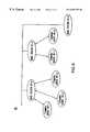
- FIG. 6illustrates another embodiment of the communications system according to the present invention.
- U-NII devicescommunicate on three different frequency bands.
- Devices which communicate on the 5.15-5.25 GHz bandcan transmit a maximum of 50 mW transmit power per device, plus a 6 dBi antenna gain.
- Devices which communicate on the 5.25-5.35 GHz bandcan transmit a maximum of 250 mw transmit power per device, plus a 6 dBi antenna gain.
- Devices which communicate on the 5.725-5.825 GHz bandcan transmit a maximum of 1 w transmit power per device, plus a 23 dBi antenna gain.
- U-NII deviceswere originally envisioned to operate on these different bands to accommodate various ranging requirements.
- the present inventionteaches a much more advantageous use of the bandwidth available for such devices.
- the present inventionhas particular advantages when used in wireless devices not intended for substantial movement, in contrast to wireless devices that are intended to move at rates of automobile speeds.
- FIG. 1Aillustrates an overview of the present invention.
- the system 10includes a base station 12 that communicates with many different terminal devices 16 .
- each terminal device 16receives downlink communications from the base station 12 .
- the terminal device 16uses another of the U-NII channels, the terminal device 16 transmits uplink communications to the base station 12 .
- the downlink communication channelwill be at a higher frequency than the uplink communication channel, although it will be appreciated that systems can be designed where this need not be the case. Accordingly, for a terminal device 16 and a base station 12 that are within a distance D from each other, as shown in FIG.
- the two different bandscan be used such that one of the uplink and downlink (preferably the downlink as described above) will have much greater capacity, due to there being more available power on that band.
- the uplink and downlinkpreferably the downlink as described above
- the transmit power as in the 5.15-5.25 GHz bandis allowed. This extra allowance in transmit power can be used to increase the aggregate bandwidth five fold for downlink transmissions as compared to uplink transmissions, if the terminal device 16 is using the 5.15-5.25 GHz band for uplink transmissions and the 5.25-5.35 GHz band for downlink transmissions.
- the distance Dis determined as that distance within which both the uplink and the downlink communications can take place and reliably transmit data. As will be appreciated, at some distance greater than D, in order to transmit the same amount of data, higher power would be necessary for at least one of the uplink or downlink. Since, however, the U-NII devices are limited by the amount of power that they can transmit, greater power cannot be used for the devices to comply with the U-NII regulations. This invention trades off data rate for lower transmit power, so that if a terminal device 16 - 3 is farther away from the base station, a lower rate communication link can be setup without violating the U-NII regulations.
- the present inventionhas particular advantages in environments in which the base station 12 and terminal devices do not move at high speeds, but rather at “human speed”, which is approximately 1 meter per second. Since the average packet length in modern wireless communication systems is fairly short, on the order of a few milliseconds, the distance traveled during one packet interval is on the order of a few millimeters, sufficiently smaller compared to the average distance between a base-station and a terminal device. This allows, therefore, initialization of communications of a given terminal device 16 with the base station 12 such that calculation of the power being used can be performed, with the knowledge that communications thereafter can continue to occur up to a maximum data rate associated with the distance between the base station and a terminal device and the maximum power of each channel being used.
- each base station 12 and terminal device 16illustrated as transmitter 100 in FIG. 1 B and receiver 200 in FIG. 1 C. It will be apparent that each base station 12 and a terminal device 16 will typically include both of a transmitter 100 and a receiver 200 . It will be understood that certain of the same components can be used in both the transmitter and receiver. For ease of understanding, however, they are separately labeled and discussed herein.
- the transmitter 100includes a digital processor 102 for digital data processing.
- a digital to analog converter 104converts the digital data from the digital processor to an analog format.
- a frequency synthesizer 106generates the appropriate carrier frequency.
- a mixer 108 for frequency up-conversioncombines the carrier frequency from the frequency synthesizer 106 with the analog data output from the digital to analog converter 104 to obtain a radio frequency transmission signal.
- a power amplifier 110performs signal amplification on the transmission signal. The transmission signal is then bandpass filtered with a bandpass filter 112 and finally transmitted using the antenna 114 .
- the receiver 200includes a receive antenna 202 that receives the transmission signal, which is then bandpass filtered using bandpass filter 204 .
- a low-noise-amplifier 206then amplifies the relatively small received radio-frequency transmission signal.
- a frequency synthesizer 208generates the appropriate carrier frequency for down-conversion.
- a mixer 210receives the carrier frequency from the frequency synthesizer and the amplified radio-frequency transmission signal and performs down-conversion to obtain an analog signal representative of the originally transmitted signal.
- An analog to digital converter 212converts the analog signal to a corresponding digital signal, and a digital processor 214 processes the received digital signal.
- multiple antennascan be used by the base station 12 or the terminal devices 16 in order to achieve spatial diversity, for the purpose of increased capacity and robustness.
- the rate of data transmission between a specific base station 12 and a specific terminal device 16are dynamically determined in the digital domain using the digital processor 102 , through either code-division multiple access or other data modulation schemes.
- the actual data rate to each terminal device 16can be dynamically allocated, given the power budget and the range between the terminal device 16 and the base-station 12 , as illustrated in FIGS. 2A-2C.
- FIGS. 2A-2Care established based upon the following assumptions: 0 dB antenna gain, ⁇ 70 dBm receiver sensitivity, 10 dB E b /N o before detection, 10 dB overall receiver noise figure, and 50 dB transmit power loss after 1 meter radius. It will be understood that the correlation between power budget and range provided in FIGS. 2A-2C is idealized, and that there will be interference effects that require more precise adjustment. This will be described further hereinafter, but FIGS. 2A-2C illustrate that different data rates are possible for the various power levels that exist within each of the U-NII bands, and thus help provide an understanding of the present invention.
- each base stationcan support up to tens of different terminal devices, with each terminal device not exceeding the maximum power level for transmissions in either direction.
- the power-distance relationshipfollows a 4-th order roll-off, i.e., the average power requirement is proportional to the 4-th order of the distance between a base-station and a terminal device.
- a rule-of-thumb calculation based on that assumptionindicates that 12 dB more power is required whenever the distance is doubled. Since the average power requirement should be proportional to the data rate in a well-designed system, whenever the distance is halved, the data rate can increase by a factor of 16 , assuming the power budget remains the same.
- the signal processor 102 in the base stationwill initiate a transmission to the terminal device 16 at the maximum power level that is allowed and predetermined low data rate, as shown in step 300 illustrated in FIG. 1 D.
- the received power level at that low data rateis determined by the signal processor 214 by way of an automatic gain control circuit (AGC), which is needed to determine the appropriate dynamic range for the ADC to function correctly in a receiver.
- ADCautomatic gain control circuit
- the signal processor 214can determine the appropriate data rate to use for transmission. Signal detection is based on the received signal energy per bit, E o which is the product of the received power and the interval per bit. If a desired level of E o has to be maintained to guarantee certain performance requirement, the received power level and the data rate are in direct proportion to each other to maintain a constant E o . Therefore in most well-designed systems, the new data rate can be determined from the received power level.
- Step 304follows, in which the signal processor 214 informs the signal processor 102 of the appropriate data rate to use for the next round of communications. Thereafter, based upon the received information the signal processor 102 will then transmit data at that data rate as shown by step 306 . If at any time during the transmission the power level changes by more than a certain threshold, such as 1 dB (step 308 ), the signal processor 214 informs the signal process or 102 of a new data rate, as shown in step 310 , and the signal processor 102 adjusts the data rate accordingly, as shown by step 312 . Further, the processor 214 , having sent the new data rate to the processor 102 , will thereafter process subsequently received data corresponding to that new rate, as shown by step 314 . This is the closed loop rate control.
- a certain thresholdsuch as 1 dB
- the signal processor 214can use the new data rate to send data to the signal processor 102 . Because the new data rate is based on the received power level at the processor 214 , assuming that the channel is symmetrical, the signal energy per bit received by the signal processor 102 will be sufficient for reliable detection. The uncertainty on the data rate for the signal processor 102 can be resolved by either one of the following two methods. First, the information of the new data rate can be sent at a predetermined low data rate by signal processor 214 and then the signal processor 214 can switch to the new data rate for data transmission, assuming that the bits which carry the information of the new data rate can be timely detected by the signal processor 102 .
- the second methoduses a set of predetermined date rates agreed upon by both processors 102 and 214 .
- the signal processor 214can choose any data rate in this set, and the signal processor 102 can reliably detect the sent data at any rate chosen from this set, as long as the received energy per bit is greater than a certain threshold, which is guaranteed by the signal processor 214 .
- the actual mechanism for detecting data without knowing the exact data rateis within the ability of those skilled in the art. This is the open loop rate control.
- Another example of the communications that can be implemented using this embodimentis the usage of the 5.725-5.825 GHz band for downlink transmissions and 5.15-5.25 GHz for uplink transmissions. Since there is more power available for the downlink transmissions, the aggregate downlink capacity can be increased accordingly.
- This examplehas the additive advantage in that the synthesizer design in both the terminal device and the base station is easier to implement, as the two bands are more widely separated.
- the 5.725-5.825 Ghz bandis used for distribution between base station 32 and repeaters 34 (for both downlink and uplink or for downlink only).
- Repeatersas are known, are used to serve as a local distributor of data. Accordingly, there will typically be a number of different repeaters 34 associated with a single base station 32 . According to the present invention, having a repeater in different rooms or different buildings is an effective way of communicating data. Similarly, a number of different terminal devices 36 can then be associated with each repeater 34 .
- the 5.25-5.35 GHz bandcan used for downlink transmissions, and the 5.15-5.25 GHz band is used for uplink transmissions.
- each repeater or the base-stationis considered as a single transceiver.
- the specific components used to make each base station 32 and terminal device 36are similar to those described above with reference to the base station 12 and terminal device 16 , respectively, of FIG. 1, whereas the components used to make each repeater 34 are similar to that of a terminal device, only that the digital data processing unit can be minimized.
- One extreme examplewould be that there is no need for ADC, digital circuit, or DAC in a repeater, as the frequency conversion task, which is composed of received signal amplification, frequency conversion, and transmitted signal amplification, can be performed completely by analog components.
- multiple antennascan be used by each of the base station 32 , repeaters 34 , or terminal devices 36 , in order to achieve spatial diversity, for the purpose of increased capacity and robustness.
- the actual bandwidth to each terminal device 36can be varied according to the individual needs and the distance between the repeater 34 and the terminal device 36 .
- the total resource available for each repeater 34is 250 mW of transmit power (plus potential 6 dBi of antenna gain) for downlink transmissions.
- the actual data rate to each terminal devicecan be dynamically allocated, given the power budget and the range between the terminal device and the repeater.
- the data rate between the base station 32 and each repeater 34can be substantially higher than the data rate between a terminal device and a repeater. The reason is that more power budget is allowed in the 5.725-5.825 GHz band, plus a substantial antenna gain, 23 dBi. With both high power and high antenna gain, the system can deliver substantially longer range and higher aggregate data rate between a base station and a repeater.
- repeaters 34 in the embodiment of FIG. 3allows better control of the transmission range, so that, for example, the data transmitted between a given repeater 34 -A and its terminal devices 36 A 1 - 36 An will not interfere with the data transmitted between another repeater 34 -B and its terminal devices 36 B 1 - 36 Bm.
- the 5.725-5.825 Ghz bandis used for distribution between base embodiment of FIG. 1 could also be made up a plurality of transceivers, with the same benefits being derived therefrom.
- a system 50provides a base station 52 and a plurality of terminal devices 56 , and each band can be used for both uplink and downlink through time division duplex (TDD) between the base station 52 and the terminal devices 56 .
- the base-station 52can be constructed as a cluster of transceivers if the aggregate downlink capacity is equal to or larger than the uplink capacity of each individual terminal device 56 , as both the terminal devices 56 and base station transceivers have the same transmit power limit.
- each base-station 62can be considered as a single transceiver or a cluster of transceivers, as has been previously discussed. If each of the base stations 62 are sufficiently apart so that the transmitted signal power in one cluster is lower than the noise floor as received by the devices in other clusters, each base station 62 and its terminal devices 66 can be considered as a stand-alone system, as set forth and described in the above embodiments.
- the systemcan still be designed using the above-described principles for both downlink transmissions and uplink transmissions.
- the individual channel to each terminal devicecan be created using either conventional code-division multiple access techniques (different codes for different terminal devices) or spatial-division multiple access techniques (use of antenna diversity).
- Ad-hoc networkis meant a network in which there is no fixed base station. Each communication link is set up dynamically through a mutually understood protocol, such as the one used by Bluetooth. Once a link is set up, the master, or the head of a cluster, should be considered as a base-station. Accordingly, once the base station is determined, one of the previously described embodiments can be implemented in such an Ad-hoc network. In other words, allowing the master node higher transmit power will accommodate a larger overall capacity for the master to transmit data to its slaves.
Landscapes
- Engineering & Computer Science (AREA)
- Computer Networks & Wireless Communication (AREA)
- Signal Processing (AREA)
- Quality & Reliability (AREA)
- Mobile Radio Communication Systems (AREA)
- Communication Control (AREA)
- Radio Relay Systems (AREA)
- Near-Field Transmission Systems (AREA)
Abstract
Description
Claims (92)
Priority Applications (15)
| Application Number | Priority Date | Filing Date | Title |
|---|---|---|---|
| US09/368,637US6697375B1 (en) | 1999-08-04 | 1999-08-04 | Method and apparatus for bandwidth and frequency management in the U-NII band |
| CA2380758ACA2380758C (en) | 1999-08-04 | 2000-07-28 | Method and apparatus for wireless communications having varying data rates |
| CNB008124981ACN100356721C (en) | 1999-08-04 | 2000-07-28 | Wireless communication method and apparatus with variable data rate |
| DE60040914TDE60040914D1 (en) | 1999-08-04 | 2000-07-28 | METHOD AND DEVICE FOR WIRELESS COMMUNICATIONS WITH VARIABLE DATA RATES |
| JP2001515571AJP4815553B2 (en) | 1999-08-04 | 2000-07-28 | Wireless communication method and apparatus having varying data rates |
| EP00953720AEP1201054B1 (en) | 1999-08-04 | 2000-07-28 | Method and apparatus for wireless communications having varying data rates |
| IL14791600AIL147916A0 (en) | 1999-08-04 | 2000-07-28 | Method and apparatus for wireless communications having varying data rates |
| AT00953720TATE415753T1 (en) | 1999-08-04 | 2000-07-28 | METHOD AND DEVICE FOR WIRELESS COMMUNICATIONS WITH VARIABLE DATA RATES |
| AU66121/00AAU764115B2 (en) | 1999-08-04 | 2000-07-28 | Method and apparatus for wireless communications having varying data rates |
| KR1020027001375AKR100729245B1 (en) | 1999-08-04 | 2000-07-28 | Method and apparatus for wireless communication with changing data rate |
| PCT/US2000/020610WO2001011815A1 (en) | 1999-08-04 | 2000-07-28 | Method and apparatus for wireless communications having varying data rates |
| TW089115614ATW511348B (en) | 1999-08-04 | 2000-08-30 | Method and apparatus for bandwidth and frequency management in the U-NII band |
| IL147916AIL147916A (en) | 1999-08-04 | 2002-01-30 | Method and apparatus for wireless communications having varying data rates |
| US10/716,544US7505479B2 (en) | 1999-08-04 | 2003-11-20 | Method and apparatus for bandwidth and frequency management in the U-NII band |
| JP2011095261AJP2011182442A (en) | 1999-08-04 | 2011-04-21 | Method and apparatus for wireless communications having varying data rates |
Applications Claiming Priority (1)
| Application Number | Priority Date | Filing Date | Title |
|---|---|---|---|
| US09/368,637US6697375B1 (en) | 1999-08-04 | 1999-08-04 | Method and apparatus for bandwidth and frequency management in the U-NII band |
Related Child Applications (1)
| Application Number | Title | Priority Date | Filing Date |
|---|---|---|---|
| US10/716,544ContinuationUS7505479B2 (en) | 1999-08-04 | 2003-11-20 | Method and apparatus for bandwidth and frequency management in the U-NII band |
Publications (1)
| Publication Number | Publication Date |
|---|---|
| US6697375B1true US6697375B1 (en) | 2004-02-24 |
Family
ID=23452094
Family Applications (2)
| Application Number | Title | Priority Date | Filing Date |
|---|---|---|---|
| US09/368,637Expired - LifetimeUS6697375B1 (en) | 1999-08-04 | 1999-08-04 | Method and apparatus for bandwidth and frequency management in the U-NII band |
| US10/716,544Expired - Fee RelatedUS7505479B2 (en) | 1999-08-04 | 2003-11-20 | Method and apparatus for bandwidth and frequency management in the U-NII band |
Family Applications After (1)
| Application Number | Title | Priority Date | Filing Date |
|---|---|---|---|
| US10/716,544Expired - Fee RelatedUS7505479B2 (en) | 1999-08-04 | 2003-11-20 | Method and apparatus for bandwidth and frequency management in the U-NII band |
Country Status (12)
| Country | Link |
|---|---|
| US (2) | US6697375B1 (en) |
| EP (1) | EP1201054B1 (en) |
| JP (2) | JP4815553B2 (en) |
| KR (1) | KR100729245B1 (en) |
| CN (1) | CN100356721C (en) |
| AT (1) | ATE415753T1 (en) |
| AU (1) | AU764115B2 (en) |
| CA (1) | CA2380758C (en) |
| DE (1) | DE60040914D1 (en) |
| IL (2) | IL147916A0 (en) |
| TW (1) | TW511348B (en) |
| WO (1) | WO2001011815A1 (en) |
Cited By (24)
| Publication number | Priority date | Publication date | Assignee | Title |
|---|---|---|---|---|
| US20020003481A1 (en)* | 2000-05-05 | 2002-01-10 | Matti Kantola | Communication devices and method of communication |
| US20020061024A1 (en)* | 2000-05-22 | 2002-05-23 | Sarnoff Corporation | Method and apparatus for providing a broadband, wireless, communications network |
| US20020080866A1 (en)* | 2000-11-30 | 2002-06-27 | Stephane Bouet | Method in short range RF communication |
| US20020115409A1 (en)* | 2001-02-21 | 2002-08-22 | Khayrallah Ali S. | Method to achieve diversity in a communication network |
| US20030002490A1 (en)* | 2000-07-18 | 2003-01-02 | Wong Piu B. | Directed maximum ratio combining methods and systems for high data rate traffic |
| US20040058685A1 (en)* | 2000-11-28 | 2004-03-25 | Mika Raitola | Allocation of shared channel data rates in a communication system |
| US20040101037A1 (en)* | 1999-08-04 | 2004-05-27 | Meng Teresa H. | Method and apparatus for bandwidth and frequency management in the U-NII band |
| US6831926B1 (en)* | 2000-10-27 | 2004-12-14 | The Boeing Company | Legacy signals databus adapter/coupler |
| US20050002348A1 (en)* | 1999-01-28 | 2005-01-06 | Holtzman Jack M. | Method and apparatus for controlling transmission power in a CDMA communication system |
| US20050111383A1 (en)* | 2003-11-21 | 2005-05-26 | Grob Matthew S. | Peer-to-peer communications |
| US7142867B1 (en)* | 2000-09-15 | 2006-11-28 | Lucent Technologies Inc. | Method of determining transmission rate from a mobile station to a base station in a wireless communication system |
| US20060280149A1 (en)* | 2003-07-22 | 2006-12-14 | Carmen Kuhl | Reader device for radio frequency identification transponder with transponder functionality |
| US20070060185A1 (en)* | 2003-09-25 | 2007-03-15 | Gwendal Simon | Method for adjusting a transmitting power in a wireless communications network |
| US20070236350A1 (en)* | 2004-01-23 | 2007-10-11 | Sebastian Nystrom | Method, Device and System for Automated Context Information Based Selective Data Provision by Identification Means |
| US20080231428A1 (en)* | 2004-03-17 | 2008-09-25 | Carmen Kuhl | Continuous Data a Provision by Radio Frequency Identification (rfid) Transponders |
| US20080238617A1 (en)* | 2004-03-19 | 2008-10-02 | Carmen Kuhl | Detector Logic and Radio Identification Device and Method for Enhancing Terminal Operations |
| US20090129358A1 (en)* | 2005-03-31 | 2009-05-21 | Nec Corporation | Communication Apparatus, Communication Method and Program |
| US20100255872A1 (en)* | 2001-11-05 | 2010-10-07 | Hitachi, Ltd. | Transmission power control method for a wireless communication system |
| US7830817B1 (en) | 2007-12-05 | 2010-11-09 | Sprint Spectrum L.P. | Vocoder selection based on location of client device |
| US20110009075A1 (en)* | 2009-07-07 | 2011-01-13 | Nokia Corporation | Data transfer with wirelessly powered communication devices |
| US20110021236A1 (en)* | 2009-07-24 | 2011-01-27 | Clear Wireless Llc | Quality of service based downlink power allocation |
| US20110222613A1 (en)* | 2010-03-12 | 2011-09-15 | Sunrise Micro Devices, Inc. | Power efficient communications |
| US8233881B2 (en) | 2000-05-05 | 2012-07-31 | Nokia Corporation | Communication devices and method of communication |
| US20180070285A1 (en)* | 2014-12-19 | 2018-03-08 | Orange | Power optimization in heterogenous networks |
Families Citing this family (25)
| Publication number | Priority date | Publication date | Assignee | Title |
|---|---|---|---|---|
| US6944121B1 (en) | 2001-03-19 | 2005-09-13 | Cisco Systems Wireless Networking (Australia) Pty Limited | Wireless computer network including a mobile appliance containing a single chip transceiver |
| US7356323B2 (en)* | 2003-12-15 | 2008-04-08 | Intel Corporation | Antenna selection for diversity combining |
| US8842581B2 (en)* | 2004-03-16 | 2014-09-23 | Nokia Corporation | Method, a device and a system for duplex communications |
| EP1760941B8 (en)* | 2004-06-25 | 2011-02-23 | Mitsubishi Denki Kabushiki Kaisha | Radio lan system, diversity apparatus, and radio lan terminal |
| DE102004064108B4 (en)* | 2004-07-06 | 2008-08-28 | Infineon Technologies Ag | Method and circuit for limiting the power of a signal composed of spread-coded signals |
| US7843867B2 (en)* | 2005-02-04 | 2010-11-30 | Toshiba America Research, Inc. | Collaborative communication for wireless local area networks |
| US7477913B2 (en)* | 2005-04-04 | 2009-01-13 | Research In Motion Limited | Determining a target transmit power of a wireless transmission according to security requirements |
| EP2357743A3 (en)* | 2005-06-17 | 2011-12-28 | Fujitsu Limited | Apparatuses for resource management and power control in multi-hop communication system |
| US8873457B2 (en) | 2006-03-15 | 2014-10-28 | Freescale Semiconductor, Inc. | Method and apparatus for enhanced data rate adaptation and lower power control in a WLAN semiconductor chip |
| US7889751B2 (en)* | 2007-03-06 | 2011-02-15 | Sudhir Aggarwal | Low power wireless communication system |
| US8891458B2 (en) | 2007-12-05 | 2014-11-18 | Qualcomm Incorporated | User equipment capability update in wireless communications |
| US7808934B2 (en)* | 2008-02-29 | 2010-10-05 | Nokia Siemens Networks Oy | TDD frame format in wireless mesh network |
| US8477737B2 (en)* | 2008-03-26 | 2013-07-02 | Alcatel Lucent | System and method to improve uplink coverage in multi-carrier systems |
| JP2009272874A (en)* | 2008-05-07 | 2009-11-19 | Sony Corp | Communication apparatus, communicating method, program, and communicating system |
| EP2242323A1 (en)* | 2009-04-17 | 2010-10-20 | Poul Jørgen Holm | An ad-hoc network and a method for configuring the ad-hoc network and a mobile repeater telephone for use in the ad-hoc network and use of the mobile repeater telephone |
| US9232441B2 (en)* | 2009-08-31 | 2016-01-05 | Qualcomm Incorporated | Power based rate selection |
| CN102104947B (en)* | 2009-12-21 | 2014-06-04 | 电信科学技术研究院 | Power allocation method and base station in space division system |
| US8260342B2 (en)* | 2010-01-06 | 2012-09-04 | Anokiwave, Inc. | Communications systems management using MM-wave based motion sensing |
| JP2012118655A (en)* | 2010-11-30 | 2012-06-21 | Shinshu Univ | Remote monitoring system |
| WO2012090274A1 (en)* | 2010-12-27 | 2012-07-05 | 三菱電機株式会社 | Relay device, station side optical communication device, communication system, and bandwidth allocation method |
| US8918102B2 (en) | 2011-07-29 | 2014-12-23 | At&T Intellectual Property I, L.P. | Method and system for selecting from a set of candidate frequency bands associated with a wireless access point |
| US8611837B2 (en)* | 2011-08-30 | 2013-12-17 | Motorola Mobility Llc | Method and apparatus for power cutback in a simultaneous dual frequency band call |
| US8780862B2 (en)* | 2011-10-14 | 2014-07-15 | The Mitre Corporation | VDL2 power control |
| CN109792289A (en)* | 2016-09-23 | 2019-05-21 | 威尔逊电子有限责任公司 | To the location-based access of selected communications band |
| JP7566362B1 (en) | 2023-03-31 | 2024-10-15 | 株式会社アクセルスペース | Information processing method, program, and information processing device |
Citations (9)
| Publication number | Priority date | Publication date | Assignee | Title |
|---|---|---|---|---|
| US5224120A (en)* | 1990-12-05 | 1993-06-29 | Interdigital Technology Corporation | Dynamic capacity allocation CDMA spread spectrum communications |
| US5619492A (en)* | 1995-06-16 | 1997-04-08 | Unisys Corporation | CDMA communication system in which bit rates are dynamically allocated |
| US5734646A (en)* | 1995-10-05 | 1998-03-31 | Lucent Technologies Inc. | Code division multiple access system providing load and interference based demand assignment service to users |
| US5825761A (en) | 1995-07-26 | 1998-10-20 | Nec Corporation | Radio communication equipment with transmission rate regulating function |
| US5923650A (en)* | 1997-04-08 | 1999-07-13 | Qualcomm Incorporated | Method and apparatus for reverse link rate scheduling |
| US5960003A (en)* | 1996-02-26 | 1999-09-28 | Deutsche Telekom Ag | Process for distributing rate and power in a multicarrier transmission of a data stream |
| US6075815A (en)* | 1997-09-17 | 2000-06-13 | Nortel Networks Corporation | Symbol-energy-to-noise-density estimation in a QPSK modulated communication system |
| US6088592A (en)* | 1996-03-25 | 2000-07-11 | Airnet Communications Corporation | Wireless system plan using in band-translators with diversity backhaul to enable efficient depolyment of high capacity base transceiver systems |
| US6091967A (en)* | 1997-04-30 | 2000-07-18 | Lucent Technologies Inc. | Scalable radio platform |
Family Cites Families (13)
| Publication number | Priority date | Publication date | Assignee | Title |
|---|---|---|---|---|
| JP2813181B2 (en)* | 1987-08-20 | 1998-10-22 | 株式会社リコー | Wireless data communication device |
| DE69223961T2 (en)* | 1991-06-03 | 1998-07-30 | British Telecommunications P.L.C., London | Radio system |
| CA2086854C (en)* | 1992-03-30 | 1998-03-31 | David Joseph Brigida | Method and system for automatic modem protocol selection in a cellular communications system |
| CH684860A5 (en)* | 1992-04-23 | 1995-01-13 | Haeni Prolectron Ag | Method and circuit for the transmission of binary data sequences. |
| JPH07111469A (en)* | 1993-10-12 | 1995-04-25 | Fujitsu Ten Ltd | Data speed switching type radio communication equipment |
| JPH07203116A (en)* | 1993-12-28 | 1995-08-04 | Matsushita Graphic Commun Syst Inc | Radio facsimile equipment |
| JPH08242478A (en)* | 1995-03-05 | 1996-09-17 | Casio Comput Co Ltd | Communications system |
| JPH08274700A (en)* | 1995-03-31 | 1996-10-18 | Toshiba Corp | Wireless communication system |
| US5805585A (en)* | 1996-08-22 | 1998-09-08 | At&T Corp. | Method for providing high speed packet data services for a wireless system |
| WO1999007105A2 (en)* | 1997-08-01 | 1999-02-11 | Salbu Research And Development (Proprietary) Limited | Power adaptation in a multi-station network |
| US6449463B1 (en)* | 1998-10-29 | 2002-09-10 | Qualcomm, Incorporated | Variable loop gain in double loop power control systems |
| US6697375B1 (en)* | 1999-08-04 | 2004-02-24 | Atheros Communications, Inc. | Method and apparatus for bandwidth and frequency management in the U-NII band |
| TWI363544B (en)* | 2007-04-23 | 2012-05-01 | Mstar Semiconductor Inc | Re-configurable communication device and managing method thereof |
- 1999
- 1999-08-04USUS09/368,637patent/US6697375B1/ennot_activeExpired - Lifetime
- 2000
- 2000-07-28JPJP2001515571Apatent/JP4815553B2/ennot_activeExpired - Lifetime
- 2000-07-28AUAU66121/00Apatent/AU764115B2/ennot_activeCeased
- 2000-07-28ATAT00953720Tpatent/ATE415753T1/ennot_activeIP Right Cessation
- 2000-07-28DEDE60040914Tpatent/DE60040914D1/ennot_activeExpired - Fee Related
- 2000-07-28ILIL14791600Apatent/IL147916A0/enactiveIP Right Grant
- 2000-07-28WOPCT/US2000/020610patent/WO2001011815A1/enactiveIP Right Grant
- 2000-07-28CNCNB008124981Apatent/CN100356721C/ennot_activeExpired - Lifetime
- 2000-07-28CACA2380758Apatent/CA2380758C/ennot_activeExpired - Lifetime
- 2000-07-28KRKR1020027001375Apatent/KR100729245B1/ennot_activeExpired - Fee Related
- 2000-07-28EPEP00953720Apatent/EP1201054B1/ennot_activeExpired - Lifetime
- 2000-08-30TWTW089115614Apatent/TW511348B/ennot_activeIP Right Cessation
- 2002
- 2002-01-30ILIL147916Apatent/IL147916A/enunknown
- 2003
- 2003-11-20USUS10/716,544patent/US7505479B2/ennot_activeExpired - Fee Related
- 2011
- 2011-04-21JPJP2011095261Apatent/JP2011182442A/enactivePending
Patent Citations (9)
| Publication number | Priority date | Publication date | Assignee | Title |
|---|---|---|---|---|
| US5224120A (en)* | 1990-12-05 | 1993-06-29 | Interdigital Technology Corporation | Dynamic capacity allocation CDMA spread spectrum communications |
| US5619492A (en)* | 1995-06-16 | 1997-04-08 | Unisys Corporation | CDMA communication system in which bit rates are dynamically allocated |
| US5825761A (en) | 1995-07-26 | 1998-10-20 | Nec Corporation | Radio communication equipment with transmission rate regulating function |
| US5734646A (en)* | 1995-10-05 | 1998-03-31 | Lucent Technologies Inc. | Code division multiple access system providing load and interference based demand assignment service to users |
| US5960003A (en)* | 1996-02-26 | 1999-09-28 | Deutsche Telekom Ag | Process for distributing rate and power in a multicarrier transmission of a data stream |
| US6088592A (en)* | 1996-03-25 | 2000-07-11 | Airnet Communications Corporation | Wireless system plan using in band-translators with diversity backhaul to enable efficient depolyment of high capacity base transceiver systems |
| US5923650A (en)* | 1997-04-08 | 1999-07-13 | Qualcomm Incorporated | Method and apparatus for reverse link rate scheduling |
| US6091967A (en)* | 1997-04-30 | 2000-07-18 | Lucent Technologies Inc. | Scalable radio platform |
| US6075815A (en)* | 1997-09-17 | 2000-06-13 | Nortel Networks Corporation | Symbol-energy-to-noise-density estimation in a QPSK modulated communication system |
Non-Patent Citations (1)
| Title |
|---|
| Wireless Local Area Networks, IEEE Communications Magazine (1997) pp. 116-126. |
Cited By (63)
| Publication number | Priority date | Publication date | Assignee | Title |
|---|---|---|---|---|
| US7233591B2 (en)* | 1999-01-28 | 2007-06-19 | Qualcomm Incorporated | Method and apparatus for controlling transmission power in a CDMA communication system |
| US20050002348A1 (en)* | 1999-01-28 | 2005-01-06 | Holtzman Jack M. | Method and apparatus for controlling transmission power in a CDMA communication system |
| US20040101037A1 (en)* | 1999-08-04 | 2004-05-27 | Meng Teresa H. | Method and apparatus for bandwidth and frequency management in the U-NII band |
| US7505479B2 (en)* | 1999-08-04 | 2009-03-17 | Atheros Communications, Inc. | Method and apparatus for bandwidth and frequency management in the U-NII band |
| US8391839B2 (en) | 2000-05-05 | 2013-03-05 | Nokia Corporation | Communication devices and method of communication |
| US20020003481A1 (en)* | 2000-05-05 | 2002-01-10 | Matti Kantola | Communication devices and method of communication |
| US8233881B2 (en) | 2000-05-05 | 2012-07-31 | Nokia Corporation | Communication devices and method of communication |
| US6990354B2 (en)* | 2000-05-05 | 2006-01-24 | Nokia Mobile Phones, Ltd. | Communication devices and method of communication |
| US20020061024A1 (en)* | 2000-05-22 | 2002-05-23 | Sarnoff Corporation | Method and apparatus for providing a broadband, wireless, communications network |
| US7194006B2 (en)* | 2000-07-18 | 2007-03-20 | Kathrein-Werke Kg | Directed maximum ratio combining methods and systems for high data rate traffic |
| US20030002490A1 (en)* | 2000-07-18 | 2003-01-02 | Wong Piu B. | Directed maximum ratio combining methods and systems for high data rate traffic |
| US7142867B1 (en)* | 2000-09-15 | 2006-11-28 | Lucent Technologies Inc. | Method of determining transmission rate from a mobile station to a base station in a wireless communication system |
| US6831926B1 (en)* | 2000-10-27 | 2004-12-14 | The Boeing Company | Legacy signals databus adapter/coupler |
| US20040058685A1 (en)* | 2000-11-28 | 2004-03-25 | Mika Raitola | Allocation of shared channel data rates in a communication system |
| US7068621B2 (en)* | 2000-11-30 | 2006-06-27 | Nokia Corporation | Method in short range RF communication |
| US20020080866A1 (en)* | 2000-11-30 | 2002-06-27 | Stephane Bouet | Method in short range RF communication |
| US20020115409A1 (en)* | 2001-02-21 | 2002-08-22 | Khayrallah Ali S. | Method to achieve diversity in a communication network |
| US7113745B2 (en)* | 2001-02-21 | 2006-09-26 | Ericsson Inc. | Method to achieve diversity in a communication network |
| US8804802B2 (en) | 2001-11-05 | 2014-08-12 | Hitachi, Ltd. | Transmission power control method for a wireless communication system |
| US8385393B2 (en)* | 2001-11-05 | 2013-02-26 | Hitachi, Ltd. | Transmission power control method for a wireless communication system |
| US20100255872A1 (en)* | 2001-11-05 | 2010-10-07 | Hitachi, Ltd. | Transmission power control method for a wireless communication system |
| US8823496B2 (en) | 2003-07-22 | 2014-09-02 | Nokia Corporation | Reader device for radio frequency identification transponder with transponder functionality |
| US9306637B2 (en) | 2003-07-22 | 2016-04-05 | Nokia Technologies Oy | Reader device for radio frequency identification transponder with transponder functionality |
| US20060280149A1 (en)* | 2003-07-22 | 2006-12-14 | Carmen Kuhl | Reader device for radio frequency identification transponder with transponder functionality |
| US8384519B2 (en) | 2003-07-22 | 2013-02-26 | Nokia Corporation | Reader device for radio frequency identification transponder with transponder functionality |
| US20070060185A1 (en)* | 2003-09-25 | 2007-03-15 | Gwendal Simon | Method for adjusting a transmitting power in a wireless communications network |
| US7672686B2 (en)* | 2003-09-25 | 2010-03-02 | France Telecom | Method for adjusting a transmitting power in a wireless communications network |
| US8060129B2 (en) | 2003-11-21 | 2011-11-15 | Qualcomm Incorporated | Peer-to-peer communications |
| US20050111383A1 (en)* | 2003-11-21 | 2005-05-26 | Grob Matthew S. | Peer-to-peer communications |
| US7539507B2 (en)* | 2003-11-21 | 2009-05-26 | Qualcomm Incorporated | Peer-to-peer communications |
| US20100050001A1 (en)* | 2003-11-21 | 2010-02-25 | Grob Matthew S | Peer-to-Peer Communications |
| US8725626B2 (en) | 2004-01-23 | 2014-05-13 | Nokia Corporation | Method, device and system for automated context information based selective data provision by identification means |
| US20070236350A1 (en)* | 2004-01-23 | 2007-10-11 | Sebastian Nystrom | Method, Device and System for Automated Context Information Based Selective Data Provision by Identification Means |
| US8225014B2 (en) | 2004-03-17 | 2012-07-17 | Nokia Corporation | Continuous data provision by radio frequency identification (RFID) transponders |
| US20080231428A1 (en)* | 2004-03-17 | 2008-09-25 | Carmen Kuhl | Continuous Data a Provision by Radio Frequency Identification (rfid) Transponders |
| US20080238617A1 (en)* | 2004-03-19 | 2008-10-02 | Carmen Kuhl | Detector Logic and Radio Identification Device and Method for Enhancing Terminal Operations |
| US9619682B2 (en) | 2004-03-19 | 2017-04-11 | Nokia Technologies Oy | Detector logic and radio identification device and method for enhancing terminal operations |
| US9881190B2 (en) | 2004-03-19 | 2018-01-30 | Nokia Technologies Oy | Detector logic and radio identification device and method for enhancing terminal operations |
| US10546164B2 (en) | 2004-03-19 | 2020-01-28 | Nokia Technologies Oy | Detector logic and radio identification device and method for enhancing terminal operations |
| US9084116B2 (en) | 2004-03-19 | 2015-07-14 | Nokia Technologies Oy | Detector logic and radio identification device and method for enhancing terminal operations |
| US20090129358A1 (en)* | 2005-03-31 | 2009-05-21 | Nec Corporation | Communication Apparatus, Communication Method and Program |
| US7830817B1 (en) | 2007-12-05 | 2010-11-09 | Sprint Spectrum L.P. | Vocoder selection based on location of client device |
| US20110009075A1 (en)* | 2009-07-07 | 2011-01-13 | Nokia Corporation | Data transfer with wirelessly powered communication devices |
| US8185146B2 (en)* | 2009-07-24 | 2012-05-22 | Clearwire Ip Holdings Llc | Quality of service based downlink power allocation |
| US8311573B1 (en) | 2009-07-24 | 2012-11-13 | Clearwire Ip Holdings Llc | Quality of service based downlink power allocation |
| US8311574B1 (en) | 2009-07-24 | 2012-11-13 | Clearwire Ip Holdings Llc | Quality of service based downlink power allocation |
| US20110021236A1 (en)* | 2009-07-24 | 2011-01-27 | Clear Wireless Llc | Quality of service based downlink power allocation |
| US20110222454A1 (en)* | 2010-03-12 | 2011-09-15 | Sunrise Micro Devices, Inc. | Power efficient communications |
| US9544004B2 (en) | 2010-03-12 | 2017-01-10 | Sunrise Micro Devices, Inc. | Power efficient communications |
| US9237526B2 (en) | 2010-03-12 | 2016-01-12 | Sunrise Micro Devices, Inc. | Power efficient communications |
| US9241315B2 (en) | 2010-03-12 | 2016-01-19 | Sunrise Micro Devices, Inc. | Power efficient communications |
| US9198134B2 (en) | 2010-03-12 | 2015-11-24 | Sunrise Micro Devices, Inc. | Power efficient communications |
| US9461688B2 (en) | 2010-03-12 | 2016-10-04 | Sunrise Micro Devices, Inc. | Power efficient communications |
| US9461689B2 (en) | 2010-03-12 | 2016-10-04 | Sunrise Micro Devices, Inc. | Power efficient communications |
| US9198133B2 (en)* | 2010-03-12 | 2015-11-24 | Sunrise Micro Devices, Inc. | Power efficient communications |
| US9548783B2 (en) | 2010-03-12 | 2017-01-17 | Sunrise Micro Devices, Inc. | Power efficient communications |
| US9553626B2 (en) | 2010-03-12 | 2017-01-24 | Sunrise Micro Devices, Inc. | Power efficient communications |
| US9564939B2 (en) | 2010-03-12 | 2017-02-07 | Sunrise Micro Devices, Inc. | Power efficient communications |
| US20110222614A1 (en)* | 2010-03-12 | 2011-09-15 | Sunrise Micro Devices, Inc. | Power efficient communications |
| US20110223874A1 (en)* | 2010-03-12 | 2011-09-15 | Sunrise Micro Devices, Inc. | Power efficient communications |
| US20110222613A1 (en)* | 2010-03-12 | 2011-09-15 | Sunrise Micro Devices, Inc. | Power efficient communications |
| US20180070285A1 (en)* | 2014-12-19 | 2018-03-08 | Orange | Power optimization in heterogenous networks |
| US10856205B2 (en)* | 2014-12-19 | 2020-12-01 | Orange | Power optimization in heterogenous networks |
Also Published As
| Publication number | Publication date |
|---|---|
| IL147916A0 (en) | 2002-08-14 |
| JP2011182442A (en) | 2011-09-15 |
| IL147916A (en) | 2007-06-03 |
| AU6612100A (en) | 2001-03-05 |
| TW511348B (en) | 2002-11-21 |
| KR100729245B1 (en) | 2007-06-15 |
| ATE415753T1 (en) | 2008-12-15 |
| AU764115B2 (en) | 2003-08-07 |
| US7505479B2 (en) | 2009-03-17 |
| CN1372736A (en) | 2002-10-02 |
| WO2001011815A1 (en) | 2001-02-15 |
| CA2380758C (en) | 2010-09-14 |
| JP2003506962A (en) | 2003-02-18 |
| DE60040914D1 (en) | 2009-01-08 |
| EP1201054B1 (en) | 2008-11-26 |
| EP1201054A1 (en) | 2002-05-02 |
| US20040101037A1 (en) | 2004-05-27 |
| JP4815553B2 (en) | 2011-11-16 |
| CN100356721C (en) | 2007-12-19 |
| KR20020038930A (en) | 2002-05-24 |
| CA2380758A1 (en) | 2001-02-15 |
Similar Documents
| Publication | Publication Date | Title |
|---|---|---|
| US6697375B1 (en) | Method and apparatus for bandwidth and frequency management in the U-NII band | |
| US6967944B2 (en) | Increasing link capacity via concurrent transmissions in centralized wireless LANs | |
| US7529218B2 (en) | High density WLAN system | |
| US5912921A (en) | Concurrent multiple data rate communications in a wireless local area network | |
| JP4489294B2 (en) | Channel allocation in a communication system with asymmetric uplink / downlink traffic | |
| EP1627537B1 (en) | Method and apparatus for channel sharing between multiple communication systems | |
| US6775558B1 (en) | Accessory interface within a multiple channel radio apparatus | |
| US20030220112A1 (en) | System and method for enabling the use of spatially distributed multichannel wireless access points/base stations | |
| US20070149232A1 (en) | Information transmission with energy budget management | |
| JP2007166669A (en) | Interference reduction in time division duplex systems using code division multiple access | |
| JPH10503337A (en) | Remote transmitter power control in a CDMA communication system | |
| JP2009017576A (en) | Wireless ultra wideband network having interference mitigation and related methods | |
| JP4083176B2 (en) | Ultra-wideband wireless network with frequency bin transmission level setting and related methods | |
| US5548805A (en) | Data communication system using spectral overlay | |
| JP2899583B1 (en) | Channel assignment device for wireless networks | |
| US20030076874A1 (en) | Reverse synchronization method in a wireless system | |
| JP3213023B2 (en) | Transmission control method and apparatus for wireless local area network station | |
| JP3387413B2 (en) | Wireless transmission / reception method | |
| GB2371438A (en) | Telecommunications system | |
| KR20190055541A (en) | Method for Controlling LBT on LTE-LAA and Nobe-B thereof |
Legal Events
| Date | Code | Title | Description |
|---|---|---|---|
| AS | Assignment | Owner name:T-SPAN SYSTEMS CORPORATION, CALIFORNIA Free format text:ASSIGNMENT OF ASSIGNORS INTEREST;ASSIGNOR:MENG, TERESA H.;REEL/FRAME:010156/0894 Effective date:19990802 | |
| AS | Assignment | Owner name:ATHEROS COMMUNCATIONS, INC., CALIFORNIA Free format text:CHANGE OF NAME;ASSIGNOR:T-SPAN SYSTEMS CORPORATION;REEL/FRAME:013402/0731 Effective date:20000508 | |
| AS | Assignment | Owner name:ATHEROS COMMUNICATIONS, INC., CALIFORNIA Free format text:CHANGE OF NAME;ASSIGNOR:T-SPAN SYSTEMS CORPORATION;REEL/FRAME:014249/0845 Effective date:20000508 | |
| STCF | Information on status: patent grant | Free format text:PATENTED CASE | |
| FEPP | Fee payment procedure | Free format text:PAT HOLDER NO LONGER CLAIMS SMALL ENTITY STATUS, ENTITY STATUS SET TO UNDISCOUNTED (ORIGINAL EVENT CODE: STOL); ENTITY STATUS OF PATENT OWNER: SMALL ENTITY | |
| FEPP | Fee payment procedure | Free format text:PAYOR NUMBER ASSIGNED (ORIGINAL EVENT CODE: ASPN); ENTITY STATUS OF PATENT OWNER: SMALL ENTITY | |
| FPAY | Fee payment | Year of fee payment:4 | |
| AS | Assignment | Owner name:THE CONNECTIVITY PATENT TRUST, CALIFORNIA Free format text:ASSIGNMENT OF ASSIGNORS INTEREST;ASSIGNOR:ATHEROS COMMUNICATIONS, INC.;REEL/FRAME:026317/0659 Effective date:20110517 | |
| FPAY | Fee payment | Year of fee payment:8 | |
| FEPP | Fee payment procedure | Free format text:PAT HOLDER CLAIMS SMALL ENTITY STATUS, ENTITY STATUS SET TO SMALL (ORIGINAL EVENT CODE: LTOS); ENTITY STATUS OF PATENT OWNER: SMALL ENTITY | |
| FPAY | Fee payment | Year of fee payment:12 |