US6697192B1 - High power, spectrally combined laser systems and related methods - Google Patents
High power, spectrally combined laser systems and related methodsDownload PDFInfo
- Publication number
- US6697192B1 US6697192B1US09/708,697US70869700AUS6697192B1US 6697192 B1US6697192 B1US 6697192B1US 70869700 AUS70869700 AUS 70869700AUS 6697192 B1US6697192 B1US 6697192B1
- Authority
- US
- United States
- Prior art keywords
- optical
- phased
- array
- outputs
- gain
- Prior art date
- Legal status (The legal status is an assumption and is not a legal conclusion. Google has not performed a legal analysis and makes no representation as to the accuracy of the status listed.)
- Expired - Fee Related
Links
Images


Classifications
- H—ELECTRICITY
- H01—ELECTRIC ELEMENTS
- H01S—DEVICES USING THE PROCESS OF LIGHT AMPLIFICATION BY STIMULATED EMISSION OF RADIATION [LASER] TO AMPLIFY OR GENERATE LIGHT; DEVICES USING STIMULATED EMISSION OF ELECTROMAGNETIC RADIATION IN WAVE RANGES OTHER THAN OPTICAL
- H01S3/00—Lasers, i.e. devices using stimulated emission of electromagnetic radiation in the infrared, visible or ultraviolet wave range
- H01S3/23—Arrangements of two or more lasers not provided for in groups H01S3/02 - H01S3/22, e.g. tandem arrangements of separate active media
- H01S3/2383—Parallel arrangements
- H—ELECTRICITY
- H01—ELECTRIC ELEMENTS
- H01S—DEVICES USING THE PROCESS OF LIGHT AMPLIFICATION BY STIMULATED EMISSION OF RADIATION [LASER] TO AMPLIFY OR GENERATE LIGHT; DEVICES USING STIMULATED EMISSION OF ELECTROMAGNETIC RADIATION IN WAVE RANGES OTHER THAN OPTICAL
- H01S3/00—Lasers, i.e. devices using stimulated emission of electromagnetic radiation in the infrared, visible or ultraviolet wave range
- H01S3/05—Construction or shape of optical resonators; Accommodation of active medium therein; Shape of active medium
- H01S3/06—Construction or shape of active medium
- H01S3/063—Waveguide lasers, i.e. whereby the dimensions of the waveguide are of the order of the light wavelength
- H01S3/067—Fibre lasers
- H01S3/0675—Resonators including a grating structure, e.g. distributed Bragg reflectors [DBR] or distributed feedback [DFB] fibre lasers
- H—ELECTRICITY
- H01—ELECTRIC ELEMENTS
- H01S—DEVICES USING THE PROCESS OF LIGHT AMPLIFICATION BY STIMULATED EMISSION OF RADIATION [LASER] TO AMPLIFY OR GENERATE LIGHT; DEVICES USING STIMULATED EMISSION OF ELECTROMAGNETIC RADIATION IN WAVE RANGES OTHER THAN OPTICAL
- H01S3/00—Lasers, i.e. devices using stimulated emission of electromagnetic radiation in the infrared, visible or ultraviolet wave range
- H01S3/05—Construction or shape of optical resonators; Accommodation of active medium therein; Shape of active medium
- H01S3/06—Construction or shape of active medium
- H01S3/063—Waveguide lasers, i.e. whereby the dimensions of the waveguide are of the order of the light wavelength
- H01S3/067—Fibre lasers
- H01S3/06754—Fibre amplifiers
- H—ELECTRICITY
- H01—ELECTRIC ELEMENTS
- H01S—DEVICES USING THE PROCESS OF LIGHT AMPLIFICATION BY STIMULATED EMISSION OF RADIATION [LASER] TO AMPLIFY OR GENERATE LIGHT; DEVICES USING STIMULATED EMISSION OF ELECTROMAGNETIC RADIATION IN WAVE RANGES OTHER THAN OPTICAL
- H01S3/00—Lasers, i.e. devices using stimulated emission of electromagnetic radiation in the infrared, visible or ultraviolet wave range
- H01S3/23—Arrangements of two or more lasers not provided for in groups H01S3/02 - H01S3/22, e.g. tandem arrangements of separate active media
- H01S3/2308—Amplifier arrangements, e.g. MOPA
- H—ELECTRICITY
- H01—ELECTRIC ELEMENTS
- H01S—DEVICES USING THE PROCESS OF LIGHT AMPLIFICATION BY STIMULATED EMISSION OF RADIATION [LASER] TO AMPLIFY OR GENERATE LIGHT; DEVICES USING STIMULATED EMISSION OF ELECTROMAGNETIC RADIATION IN WAVE RANGES OTHER THAN OPTICAL
- H01S5/00—Semiconductor lasers
- H01S5/40—Arrangement of two or more semiconductor lasers, not provided for in groups H01S5/02 - H01S5/30
- H01S5/4025—Array arrangements, e.g. constituted by discrete laser diodes or laser bar
- H—ELECTRICITY
- H01—ELECTRIC ELEMENTS
- H01S—DEVICES USING THE PROCESS OF LIGHT AMPLIFICATION BY STIMULATED EMISSION OF RADIATION [LASER] TO AMPLIFY OR GENERATE LIGHT; DEVICES USING STIMULATED EMISSION OF ELECTROMAGNETIC RADIATION IN WAVE RANGES OTHER THAN OPTICAL
- H01S5/00—Semiconductor lasers
- H01S5/50—Amplifier structures not provided for in groups H01S5/02 - H01S5/30
Definitions
- the present inventionrelates generally to high-power laser systems, an in particular to systems that combine the beams of multiple lasers to expand output power and bandwidth.
- High-power, high-brightness lasersare utilized in a wide variety of industrial, optical, and medical applications.
- laser poweris carried by optical fibers, which can be single-mode or multimode in nature, depending on the application.
- the light-carrying cores of single-mode fibersare narrower than those of multimode fibers. Because light travels more quickly through smaller cores and also suffers less attenuation, single-mode fibers are preferred for applications involving high-frequency light pulses and long travel distances.
- a laserIn order to couple to a small fiber core (the size of which is typically expressed as an “étendue,” i.e., the product of the fiber's core diameter and numerical aperture), a laser must have a small-diameter, narrow-divergence output beam and, therefore, a high brightness level. Unfortunately, typical high-power lasers do not exhibit sufficient brightness levels to permit coupling into single-mode fibers.
- étenduethe size of which is typically expressed as an “étendue,” i.e., the product of the fiber's core diameter and numerical aperture
- an external laser resonatormay be based on a bar of light-emitting semiconductor material whose outputs emerge from a linear sequence of stripes along the length of the bar.
- outputspass through an output-coupling lens and strike a dispersive element, such as a diffraction grating.
- a dispersive elementsuch as a diffraction grating.
- Light dispersed by the dispersive elementis reflected by a partial mirror back along the optical path, passing through the lens and returning to the semiconductor outputs, the opposite facets of which are reflective.
- the resulting feedbackproduces laser amplification, and light not reflected by the partial mirror represents the output of the system.
- the reflective semiconductor facets and the partial mirrortogether form an ensemble of individual, external-cavity lasers, each with its own optical path.
- the lens and dispersive elementforce the individual beams into a coaxial configuration, their paths intercepting at the dispersive element.
- each laserhas a different optical path and, therefore, resonates at a different wavelength.
- the overall resultis a high-power, multi-wavelength beam with high brightness due to the coaxially overlapping component beams.
- either or both of two strategiesis employed to increase system output.
- the external-resonator designis modified to allow each input to undergo individual amplification notwithstanding optical beam combination. In this way, overall output power may be scaled in a desired fashion, depending on the selected characteristics of the optical amplifier elements.
- each of the amplifiersmay implemented as a phased array. Viewed more generally, this configuration affords beam combining in two stages, with each contributing input source itself composed of multiple sources whose outputs have been combined. If each phased-array source emits at a different wavelength (i.e., has a different output wavelength profile), this design offers a multi-wavelength output whose power level may be scaled in accordance with the number and character of the devices forming each phased array.
- the inventioncomprises a multi-wavelength light-generation system based on an optical source that produces a plurality of spatially separated optical outputs having different wavelength profiles.
- An optical amplifierhaving a plurality of optical gain elements receives the optical outputs and amplifies them.
- the amplified outputsare directed onto a dispersive optical device, which spatially combines them in the near and far fields, resulting in a co-propagated multi-spectral output.
- the inventioncomprises a multi-wavelength light-generation system based on a series of phased-array optical gain sources.
- each of the gain sourcesutilizes the combined outputs of a plurality of constituent radiation sources arranged in a phased array.
- Each of the various phased-array gain sourcesproduces an output having a different wavelength profile. These outputs are spatially combined by a dispersive optical device.
- FIG. 1Aschematically illustrates an amplified, spectrally combined laser in accordance with the invention
- FIG. 1Billustrates a variation of the design shown in FIG. 1A, with output being derived from a different optical location
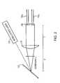
- FIG. 2illustrates implementation of the invention using a mode-locked laser
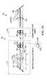
- FIG. 3schematically illustrates an amplified, spectrally combined laser in which the amplifiers are implemented as phased arrays
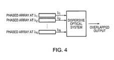
- FIG. 4is a block diagram of a hybrid optical beam-combining system in accordance with the present invention.
- FIG. 1Ashows an amplified laser 100 in which spectrally distinct outputs are spatially combined.
- the illustrated designcomprises an optical source 110 producing multiple optical outputs having different wavelengths; a power amplifier array 115 ; and an output stage 120 .
- source 110is implemented as an external-cavity master-oscillator array.
- the arrayincludes a set of optical gain elements 122 1 . . . 122 n ; an optical device (such as a collimating lens and/or a curved mirror) 125 ; a dispersive element (such as a diffraction grating or prism) 127 ; and a reflective device (such as a mirror) 130 .
- gain elements 122are gain fibers, e.g., optical fibers doped with a gain material such as ytterbium (Yb), erbium (Er), or neodymium (Nd). Each fiber has an emission face 132 , . . . 132 n and an output face, one of which is representatively shown in enlarged form at 134 n .
- the output faces of gain elements 122are provided with partial-mirror surfaces.
- gain elements 122are excited so as to emit radiation through (at least) faces 132 .
- each gain element 122is stimulated with optical radiation delivered by a source fiber.
- light from the source fibermay be coupled into a gain fiber 122 by fusing the source fiber to the gain fiber in a parallel fashion.
- a V-groovemay be introduced radially into the thickness of a gain fiber 122 , and the output of the source fiber directed into the V-groove (i.e., normal to axis of gain fiber 122 ).
- the gain elements 122may be excited by application of an electric current (if, for example, the gain elements 122 are semiconductor elements).
- each of the gain elements 122emits a beam of radiation having a different free-space optical path.
- the radiation beams from gain elements 122all pass through optical device 125 and strike dispersive element 127 .
- Optical device 125causes the radiation beams to overlap as they reach dispersive element 127 .
- device 125may be a lens positioned substantially a focal-length distance away from both emission faces 132 and dispersive element 127 .
- the light reflected from dispersive element 127 toward mirror 130is a composite of the individual beams, which emerge from dispersive element 127 coaxially and normal to mirror 130 , which is preferably a high reflector.
- This configurationforms a resonator.
- the optical paths of the beams from gain elements 122all pass through device 125 and are all dispersed by element 127 —that is, all beams share device 125 and element 127 —but pass through only one of the gain elements 122 .
- Light reflected by mirror 130 and received through one of the emission faces 132is again partially reflected by the fiber's output face 134 , the unreflected portion of the beam representing the output.
- the pumped gain media 122together form an ensemble of individual external-cavity lasers. Because the beam of each of these lasers is incident on dispersive element 127 at a different angle, each lases at a different wavelength. That wavelength, in turn, is determined by the beam's angle of incidence with respect to dispersive element and its angle of diffraction, the optical characteristics of the gain medium, and the grating line spacing of the dispersive element 127 . Thus, by varying one or more of these parameters (most simply, the orientation and/or location of dispersive element 127 relative to emission faces 132 ), the wavelengths of the lasers may be tuned. The tuning range depends on the gain bandwidth of the gain media 122 and the reflectivity of the end faces 134 . The number of gain media 122 and their locations can be selected so as to generate simultaneously or sequentially any set of wavelengths within the gain width of the gain media.
- outputis taken from a different optical location within master-oscillator array 110 .
- a partially reflecting beamsplitter 140intercepts the beams between optical device 125 and the emission faces 132 of gain fibers 122 .
- the ends 134 of gain fibers 122are fully rather than partially reflective.
- gain elements 122 and amplifier elements 150are depicted as physically distinct. It is possible, however, for the gain and amplifier elements to be physically connected, with the output ends 134 being internal to the structure.
- fiber Bragg gratingsmay be used to form a partial reflector for the gain element as well as to differentiate between the gain elements and the amplifier elements.
- the individual, wavelength-differentiated outputs of master-oscillator array 110are provided—either directly or, in the embodiment shown in FIG. 1B, via a pair of lenses 145 , 147 —to power-amplifier array 115 , which comprises a series of individual amplifier elements 150 1 . . . 150 n , each receiving a different one of the outputs. Accordingly, different spectral regions are amplified by different ones of the amplifier elements 150 . As illustrated, amplifier elements 150 may be optical gain fibers doped, for example, with Yb or Er.
- the amplified outputs from array 115pass through an optical device 155 (e.g., a lens) and strike another dispersive element 160 .
- Optical device 155causes the radiation beams to overlap as they reach dispersive element 160 , and the light reflected from dispersive element 160 —representing the ultimate output of the system 100 —is a composite of the individual beams, which emerge coaxially.
- the combination of the optical device 155 and dispersive element 160forces overlap of the various wavelength outputs in the near and far fields.
- array 110may be simply a series of individual, physically distinct laser devices, or may instead not be an array at all—e.g., a single source with multispectral or broadband output that is split so that, once again, different spectral regions are amplified by different amplifier elements 150 .
- This approachis illustrated in FIG. 2 using a mode-locked laser, i.e., a device that outputs a train of short pulses with broad spectral bandwidth. As shown in the figure, the output of a mode-locked laser 170 strikes a dispersive element 127 , and the wavelength of light diffracted therefrom varies with angle.
- a transform lens 175converts this variation of wavelength with angle to variation with position at the focal plane of the lens, where a microlens array 180 focuses different segments of the beam (and, therefore, different wavelength bands) onto the front faces of optical gain elements 1501 . . . 150 n .
- amplifier array 115may be realized as a phased array for even greater power. Instead of being received by a single amplifying element, each output of master-oscillator array 110 serves as the input to one of N amplifier phased arrays 165 1 . . . 165 n of 1 ⁇ M gain elements each (where M may range, for example from 2 to 100).
- Nmay range, for example from 2 to 100.
- a single element 122 and the phased-array amplifier 165 it feedsconstitute an individual laser subsystem.
- the outputs from the amplifier phased arrays 165are propagated to the dispersive optical system as discussed above.
- Amplifier phased arrays suitable for use in the present contextare well known. Suitable configurations include ridge waveguide amplifiers (see IEEE Photonics Tech. Letters 6:1062 (1994)) and multisection slabs (see IEEE J. Quantum Electronics 30:2617 (1994).
- the combination of phased-array input sources producing spatially and spectrally distinct outputs with a dispersive optical system for combining those outputs in the near and far fieldoffers the possibility of continuous scaling to very large arrays at high output power levels. Moreover, because both beam-combining techniques operate essentially independently, the scaling of one does not place stress on the other. If, for example, the dispersive optics can handle 100 inputs at different wavelengths, and it is possible to configure each input as a phased array of 100 constituent laser elements, the result is a 10,000-element laser system.
Landscapes
- Physics & Mathematics (AREA)
- Electromagnetism (AREA)
- Engineering & Computer Science (AREA)
- Plasma & Fusion (AREA)
- Optics & Photonics (AREA)
- Lasers (AREA)
Abstract
Description
This invention was made with government support under Contract No. F19628-95-C-0002 awarded by the U.S. Air Force. The government has certain rights in the invention.
The present invention relates generally to high-power laser systems, an in particular to systems that combine the beams of multiple lasers to expand output power and bandwidth.
High-power, high-brightness lasers are utilized in a wide variety of industrial, optical, and medical applications. For many such applications laser power is carried by optical fibers, which can be single-mode or multimode in nature, depending on the application. The light-carrying cores of single-mode fibers are narrower than those of multimode fibers. Because light travels more quickly through smaller cores and also suffers less attenuation, single-mode fibers are preferred for applications involving high-frequency light pulses and long travel distances.
In order to couple to a small fiber core (the size of which is typically expressed as an “étendue,” i.e., the product of the fiber's core diameter and numerical aperture), a laser must have a small-diameter, narrow-divergence output beam and, therefore, a high brightness level. Unfortunately, typical high-power lasers do not exhibit sufficient brightness levels to permit coupling into single-mode fibers.
Copending U.S. Ser. No. 09/149,610 (filed Sep. 8, 1998) now U.S. Pat. No. 6,208,679 U.S. Ser. No. 09/337,081 (filed Jun. 21, 1999), and U.S. Ser. No. 09/498,462 (filed Feb. 4, 2000) now U.S. Pat. No. 6,192,062 describe external-cavity laser designs that generate coaxially overlapping outputs at multiple wavelengths. For example, an external laser resonator may be based on a bar of light-emitting semiconductor material whose outputs emerge from a linear sequence of stripes along the length of the bar. These outputs pass through an output-coupling lens and strike a dispersive element, such as a diffraction grating. Light dispersed by the dispersive element is reflected by a partial mirror back along the optical path, passing through the lens and returning to the semiconductor outputs, the opposite facets of which are reflective. The resulting feedback produces laser amplification, and light not reflected by the partial mirror represents the output of the system.
The reflective semiconductor facets and the partial mirror together form an ensemble of individual, external-cavity lasers, each with its own optical path. The lens and dispersive element force the individual beams into a coaxial configuration, their paths intercepting at the dispersive element. Moreover, because the beam of each of these lasers strikes the dispersive element at a different angle, each laser has a different optical path and, therefore, resonates at a different wavelength. The overall result is a high-power, multi-wavelength beam with high brightness due to the coaxially overlapping component beams.
Although this configuration produces high output power levels, those levels ultimately depend on the inputs to the system—i.e., the light produced by the semiconductor bar. And because the power of semiconductor emitters is limited, overall system power will be limited as well.
In accordance with the present invention, either or both of two strategies is employed to increase system output. In one approach, the external-resonator design is modified to allow each input to undergo individual amplification notwithstanding optical beam combination. In this way, overall output power may be scaled in a desired fashion, depending on the selected characteristics of the optical amplifier elements.
To achieve additional power, each of the amplifiers may implemented as a phased array. Viewed more generally, this configuration affords beam combining in two stages, with each contributing input source itself composed of multiple sources whose outputs have been combined. If each phased-array source emits at a different wavelength (i.e., has a different output wavelength profile), this design offers a multi-wavelength output whose power level may be scaled in accordance with the number and character of the devices forming each phased array.
Thus, in one aspect, the invention comprises a multi-wavelength light-generation system based on an optical source that produces a plurality of spatially separated optical outputs having different wavelength profiles. An optical amplifier having a plurality of optical gain elements receives the optical outputs and amplifies them. The amplified outputs are directed onto a dispersive optical device, which spatially combines them in the near and far fields, resulting in a co-propagated multi-spectral output.
In another aspect, the invention comprises a multi-wavelength light-generation system based on a series of phased-array optical gain sources. In particular, each of the gain sources utilizes the combined outputs of a plurality of constituent radiation sources arranged in a phased array. Each of the various phased-array gain sources produces an output having a different wavelength profile. These outputs are spatially combined by a dispersive optical device.
The foregoing discussion will be understood more readily from the following detailed description of the invention, when taken in conjunction with the accompanying drawings, in which:
FIG. 1A schematically illustrates an amplified, spectrally combined laser in accordance with the invention;
FIG. 1B illustrates a variation of the design shown in FIG. 1A, with output being derived from a different optical location;
FIG. 2 illustrates implementation of the invention using a mode-locked laser;
FIG. 3 schematically illustrates an amplified, spectrally combined laser in which the amplifiers are implemented as phased arrays; and
FIG. 4 is a block diagram of a hybrid optical beam-combining system in accordance with the present invention.
Refer first to FIG. 1A, which shows an amplifiedlaser 100 in which spectrally distinct outputs are spatially combined. The illustrated design comprises anoptical source 110 producing multiple optical outputs having different wavelengths; apower amplifier array 115; and anoutput stage 120.
In the embodiment shown in FIG. 1A,source 110 is implemented as an external-cavity master-oscillator array. The array includes a set of optical gain elements1221. . .122n; an optical device (such as a collimating lens and/or a curved mirror)125; a dispersive element (such as a diffraction grating or prism)127; and a reflective device (such as a mirror)130. As illustrated, gain elements122 are gain fibers, e.g., optical fibers doped with a gain material such as ytterbium (Yb), erbium (Er), or neodymium (Nd). Each fiber has an emission face132, . . .132nand an output face, one of which is representatively shown in enlarged form at134n. The output faces of gain elements122 are provided with partial-mirror surfaces.
In operation, gain elements122 are excited so as to emit radiation through (at least) faces132. This can be achieved in any of various known ways. Typically, each gain element122 is stimulated with optical radiation delivered by a source fiber. For example, light from the source fiber may be coupled into a gain fiber122 by fusing the source fiber to the gain fiber in a parallel fashion. Alternatively, a V-groove may be introduced radially into the thickness of a gain fiber122, and the output of the source fiber directed into the V-groove (i.e., normal to axis of gain fiber122). In another approach, the gain elements122 may be excited by application of an electric current (if, for example, the gain elements122 are semiconductor elements).
In any case, each of the gain elements122 emits a beam of radiation having a different free-space optical path. The radiation beams from gain elements122 all pass throughoptical device 125 and strikedispersive element 127.Optical device 125 causes the radiation beams to overlap as they reachdispersive element 127. For example,device 125 may be a lens positioned substantially a focal-length distance away from both emission faces132 anddispersive element 127. The light reflected fromdispersive element 127 towardmirror 130 is a composite of the individual beams, which emerge fromdispersive element 127 coaxially and normal tomirror 130, which is preferably a high reflector.
This configuration forms a resonator. The optical paths of the beams from gain elements122 all pass throughdevice 125 and are all dispersed byelement 127—that is, all beams sharedevice 125 andelement 127—but pass through only one of the gain elements122. Light reflected bymirror 130 and received through one of the emission faces132 is again partially reflected by the fiber's output face134, the unreflected portion of the beam representing the output.
The pumped gain media122 together form an ensemble of individual external-cavity lasers. Because the beam of each of these lasers is incident ondispersive element 127 at a different angle, each lases at a different wavelength. That wavelength, in turn, is determined by the beam's angle of incidence with respect to dispersive element and its angle of diffraction, the optical characteristics of the gain medium, and the grating line spacing of thedispersive element 127. Thus, by varying one or more of these parameters (most simply, the orientation and/or location ofdispersive element 127 relative to emission faces132), the wavelengths of the lasers may be tuned. The tuning range depends on the gain bandwidth of the gain media122 and the reflectivity of the end faces134. The number of gain media122 and their locations can be selected so as to generate simultaneously or sequentially any set of wavelengths within the gain width of the gain media.
In an alternative configuration, shown in FIG. 1B, output is taken from a different optical location within master-oscillator array 110. In particular, a partially reflectingbeamsplitter 140 intercepts the beams betweenoptical device 125 and the emission faces132 of gain fibers122. In this configuration, the ends134 of gain fibers122 are fully rather than partially reflective.
With renewed reference to FIG. 1A, gain elements122 and amplifier elements150 are depicted as physically distinct. It is possible, however, for the gain and amplifier elements to be physically connected, with the output ends134 being internal to the structure. For instance, in the case of optical-fiber gain elements and amplifier elements, fiber Bragg gratings may be used to form a partial reflector for the gain element as well as to differentiate between the gain elements and the amplifier elements.
Regardless of configuration, the individual, wavelength-differentiated outputs of master-oscillator array 110 are provided—either directly or, in the embodiment shown in FIG. 1B, via a pair oflenses amplifier array 115, which comprises a series of individual amplifier elements1501. . .150n, each receiving a different one of the outputs. Accordingly, different spectral regions are amplified by different ones of the amplifier elements150. As illustrated, amplifier elements150 may be optical gain fibers doped, for example, with Yb or Er.
The amplified outputs fromarray 115 pass through an optical device155 (e.g., a lens) and strike anotherdispersive element 160.Optical device 155 causes the radiation beams to overlap as they reachdispersive element 160, and the light reflected fromdispersive element 160—representing the ultimate output of thesystem 100—is a composite of the individual beams, which emerge coaxially. The combination of theoptical device 155 anddispersive element 160 forces overlap of the various wavelength outputs in the near and far fields.
It should be stressed that still other configurations are possible for master-oscillator array 110. For example,array 110 may be simply a series of individual, physically distinct laser devices, or may instead not be an array at all—e.g., a single source with multispectral or broadband output that is split so that, once again, different spectral regions are amplified by different amplifier elements150. This approach is illustrated in FIG. 2 using a mode-locked laser, i.e., a device that outputs a train of short pulses with broad spectral bandwidth. As shown in the figure, the output of a mode-lockedlaser 170 strikes adispersive element 127, and the wavelength of light diffracted therefrom varies with angle. Atransform lens 175 converts this variation of wavelength with angle to variation with position at the focal plane of the lens, where amicrolens array 180 focuses different segments of the beam (and, therefore, different wavelength bands) onto the front faces ofoptical gain elements 1501 . . .150n.
As shown in FIG. 3,amplifier array 115 may be realized as a phased array for even greater power. Instead of being received by a single amplifying element, each output of master-oscillator array 110 serves as the input to one of N amplifier phased arrays1651. . .165nof 1×M gain elements each (where M may range, for example from 2 to 100). In the implementation illustrated in FIG. 3, a single element122 and the phased-array amplifier165 it feeds constitute an individual laser subsystem. The outputs from the amplifier phased arrays165 are propagated to the dispersive optical system as discussed above.
Amplifier phased arrays suitable for use in the present context are well known. Suitable configurations include ridge waveguide amplifiers (seeIEEE Photonics Tech. Letters6:1062 (1994)) and multisection slabs (seeIEEE J. Quantum Electronics30:2617 (1994).
As shown more generally in FIG. 4, the combination of phased-array input sources producing spatially and spectrally distinct outputs with a dispersive optical system for combining those outputs in the near and far field offers the possibility of continuous scaling to very large arrays at high output power levels. Moreover, because both beam-combining techniques operate essentially independently, the scaling of one does not place stress on the other. If, for example, the dispersive optics can handle 100 inputs at different wavelengths, and it is possible to configure each input as a phased array of 100 constituent laser elements, the result is a 10,000-element laser system.
Although the present invention has been described with reference to specific details, it is not intended that such details should be regarded as limitations upon the scope of the invention, except as and to the extent that they are included in the accompanying claims.
Claims (10)
1. A multi-wavelength light-generation system comprising:
a. a plurality of phased-array optical gain sources, each phased-array optical gain source having an output wavelength, and each phased-array optical gain source comprising a plurality of constituent radiation sources arranged in a phased array and having substantially similar output wavelengths associated with the output wavelength of the phased-array optical gain source, whereby the plurality of constituent radiation sources have outputs that are combined into a phased-array optical gain source output at the output wavelength of the associated phased-array optical gain source, thereby providing a plurality of optical gain source outputs of the plurality of phased-array optical gain sources, the plurality of phased-array optical gain source outputs being spatially separated and having different output wavelengths; and
b. a dispersive optical device for spatially combining the plurality of phased-array optical gain source outputs.
2. The system ofclaim 1 wherein the phased-array outputs are substantially overlapped and co-propagated by the dispersive optical device.
3. The system ofclaim 1 wherein each gain source comprises:
a. a laser producing a laser output at the output wavelength; and
b. a phased array of optical amplifiers receiving the laser output and producing the source output therefrom.
4. The system ofclaim 3 wherein the optical amplifiers are doped optical fibers.
5. The system ofclaim 4 wherein the optical fibers are doped with Yb, Er or Nd.
6. The system ofclaim 3 wherein the lasers are constituents of an optical oscillator comprising:
a. a plurality of optical gain elements each producing one of the laser outputs;
b. a diffractive element; and
c. an optical device, light from the optical gain elements being directed by the optical device onto the diffractive element and returned to the optical gain elements so as to force the gain elements to produce the laser outputs at different resonant wavelengths.
7. The system ofclaim 6 wherein the optical oscillator further comprises a reflector for returning light from the diffractive element to the optical gain elements.
8. The system ofclaim 6 wherein the optical device is a lens or a mirror having a focal length, the optical device being disposed between the optical gain elements and the diffractive element, a distance substantially equal to the focal length intervening between the diffractive element and the optical device, and between the optical device and the optical gain elements.
9. The system ofclaim 1 wherein the source comprises:
a. a single light source producing a multispectral or broadband light output;
b. a plurality of optical amplifiers, the optical amplifiers being organized into a plurality of phased arrays; and
c. a spectrum splitter directing different spectral regions of the light output to each of the amplifier phased arrays, whereby each phased array amplifies a different spectral region, the amplifiers collectively producing the phased-array outputs.
10. A multi-wavelength light-generation system comprising:
an optical source that is an optical oscillator comprising
a. a plurality of optical gain elements each producing an output,
b. a diffractive element, and
c. an optical device, the outputs from the optical gain elements being overlapped and directed by the optical device onto the diffractive element and returned to the optical gain elements so as to force the gain elements to produce the outputs at different resonant wavelengths;
an optical amplifier comprising a plurality of amplifier elements, the plurality of amplifier elements receiving the optical outputs and producing therefrom a plurality of amplified outputs, wherein the plurality of amplifier elements and the plurality of gain elements are physically connected; and
a dispersive optical device for spatially combining the plurality of amplified outputs.
Priority Applications (1)
| Application Number | Priority Date | Filing Date | Title |
|---|---|---|---|
| US09/708,697US6697192B1 (en) | 2000-11-08 | 2000-11-08 | High power, spectrally combined laser systems and related methods |
Applications Claiming Priority (1)
| Application Number | Priority Date | Filing Date | Title |
|---|---|---|---|
| US09/708,697US6697192B1 (en) | 2000-11-08 | 2000-11-08 | High power, spectrally combined laser systems and related methods |
Publications (1)
| Publication Number | Publication Date |
|---|---|
| US6697192B1true US6697192B1 (en) | 2004-02-24 |
Family
ID=31496246
Family Applications (1)
| Application Number | Title | Priority Date | Filing Date |
|---|---|---|---|
| US09/708,697Expired - Fee RelatedUS6697192B1 (en) | 2000-11-08 | 2000-11-08 | High power, spectrally combined laser systems and related methods |
Country Status (1)
| Country | Link |
|---|---|
| US (1) | US6697192B1 (en) |
Cited By (32)
| Publication number | Priority date | Publication date | Assignee | Title |
|---|---|---|---|---|
| US20030016421A1 (en)* | 2000-06-01 | 2003-01-23 | Small James G. | Wireless communication system with high efficiency/high power optical source |
| US6992829B1 (en)* | 2001-09-19 | 2006-01-31 | Mbda Uk Limited | Apparatus for directing electromagnetic radiation |
| US7239777B1 (en) | 2006-03-09 | 2007-07-03 | Lockheed Martin Coherent Technologies, Inc. | Method and apparatus to coherently combine high-power beams in self-imaging waveguides |
| US20070211995A1 (en)* | 2006-03-09 | 2007-09-13 | Christensen Scott E | Laser beam transformation and combination using tapered waveguides |
| US7286582B1 (en)* | 2003-10-08 | 2007-10-23 | Fay Jr Theodore Denis | Optical external cavities having brewster angle wedges |
| US7339727B1 (en) | 2003-01-30 | 2008-03-04 | Northrop Grumman Corporation | Method and system for diffractive beam combining using DOE combiner with passive phase control |
| US7346085B1 (en) | 2006-10-05 | 2008-03-18 | Northrop Grumman Corporation | Multi-stage method and system for coherent diffractive beam combining |
| US20080084605A1 (en)* | 2006-10-05 | 2008-04-10 | Rothenberg Joshua E | Method and system for hybrid coherent and incoherent diffractive beam combining |
| US20080084598A1 (en)* | 2006-10-05 | 2008-04-10 | Rothenberg Joshua E | Method and system for coherent beam combining using an integrated diffractive beam combiner and sampler |
| US20080296508A1 (en)* | 2004-11-05 | 2008-12-04 | Small James G | Optical magnetron for high efficiency production of optical radiation and related methods of use |
| US7535631B2 (en) | 2005-01-26 | 2009-05-19 | Lockheed Martin Corporation | Method and apparatus for spectral-beam combining of fiber-amplified laser beams using high-efficiency dielectric diffractive gratings |
| US20090180498A1 (en)* | 2008-01-16 | 2009-07-16 | General Atomics | Coherent Beam Combiner Based on Parametric Conversion |
| DE112007002367T5 (en) | 2006-10-05 | 2009-08-13 | Northrop Grumman Corp., Los Angeles | Method and system for the diffractive combination of beams through a DOE beamformer with passive phase control |
| US20090229651A1 (en)* | 2008-03-14 | 2009-09-17 | Fay Jr Theodore Denis | Solar energy production system |
| US20110068279A1 (en)* | 2009-08-11 | 2011-03-24 | Fay Jr Theodore Denis | Ultra dark field microscope |
| US20110122482A1 (en)* | 2009-11-23 | 2011-05-26 | Lockheed Martin Corporation | Spectrally beam combined laser system and method at eye-safer wavelengths |
| US8179594B1 (en) | 2007-06-29 | 2012-05-15 | Lockheed Martin Corporation | Method and apparatus for spectral-beam combining of fanned-in laser beams with chromatic-dispersion compensation using a plurality of diffractive gratings |
| US8199399B1 (en) | 2006-11-30 | 2012-06-12 | Lockheed Martin Corporation | Optical gain fiber having segments of differing core sizes and associated method |
| EP2477285A1 (en) | 2011-01-18 | 2012-07-18 | Bystronic Laser AG | Laser diode bar and laser system |
| DE102011003142A1 (en) | 2011-01-26 | 2012-07-26 | Trumpf Laser Gmbh + Co. Kg | Diode laser arrangement has dispersive optical device that diffracts laser beams collimated by collimator lens, and focusing device focuses laser beam on entry-side end of fiber |
| WO2012131450A1 (en)* | 2011-03-29 | 2012-10-04 | Gigaphoton Inc. | Laser device, laser apparatus, and extreme ultraviolet light generation system |
| US8411712B2 (en) | 2010-04-12 | 2013-04-02 | Lockheed Martin Corporation | Beam diagnostics and feedback system and method for spectrally beam-combined lasers |
| US8472763B1 (en) | 2005-07-29 | 2013-06-25 | Lockheed Martin Corporation | Spectral beam combination of laser beams |
| US8503840B2 (en) | 2010-08-23 | 2013-08-06 | Lockheed Martin Corporation | Optical-fiber array method and apparatus |
| US8526110B1 (en) | 2009-02-17 | 2013-09-03 | Lockheed Martin Corporation | Spectral-beam combining for high-power fiber-ring-laser systems |
| US20130235448A1 (en)* | 2010-08-31 | 2013-09-12 | Friedrich-Schiller-Universitaet Jena | Optical amplifier arrangement |
| US9134538B1 (en) | 2013-02-06 | 2015-09-15 | Massachusetts Institute Of Technology | Methods, systems, and apparatus for coherent beam combining |
| US9366872B2 (en) | 2014-02-18 | 2016-06-14 | Lockheed Martin Corporation | Apparatus and method for fiber-laser output-beam shaping for spectral beam combination |
| US9417366B2 (en) | 2013-07-30 | 2016-08-16 | Northrop Grumman Systems Corporation | Hybrid diffractive optical element and spectral beam combination grating |
| US9735537B1 (en) | 2016-04-12 | 2017-08-15 | Northrop Grumman Systems Corporation | Hybrid spectral and coherent beam combiner utilizing 1D fiber arrays |
| DE102018112253A1 (en)* | 2018-05-22 | 2019-11-28 | Grintech Gmbh | Optical arrangement for a spectroscopic imaging method and spectroscopic imaging method |
| US10705269B2 (en) | 2018-03-30 | 2020-07-07 | Northrop Grumman Systems Corporation | Fabrication method of a diffractive optic for hybrid coherent and spectral beam combination |
Citations (53)
| Publication number | Priority date | Publication date | Assignee | Title |
|---|---|---|---|---|
| US3586995A (en)* | 1970-05-21 | 1971-06-22 | Hughes Aircraft Co | Multibeam laser |
| US4264869A (en)* | 1978-11-13 | 1981-04-28 | Hunter Robert O | Compressed pulse laser |
| US4710937A (en)* | 1985-06-13 | 1987-12-01 | Mitsubishi Denki Kabushiki Kaisha | Laser system |
| US4757268A (en)* | 1985-05-22 | 1988-07-12 | Hughes Aircraft Company | Energy scalable laser amplifier |
| US4794345A (en)* | 1986-02-26 | 1988-12-27 | Trw Inc. | Phased array combination of laser beams |
| US4856010A (en) | 1988-07-18 | 1989-08-08 | Hughes Aircraft Company | Laser frequency control |
| FR2630268A1 (en) | 1988-04-19 | 1989-10-20 | Bertin & Cie | METHOD AND DEVICE FOR IMPROVING THE DIRECTIVITY OF THE EMISSION OF A SOLID LASER DIODE |
| US5081637A (en)* | 1989-11-28 | 1992-01-14 | Massachusetts Institute Of Technology | Multiple-laser pump optical system |
| US5095487A (en)* | 1990-12-14 | 1992-03-10 | The University Of Rochester | System for generating pluralities of optical pulses with predetermined frequencies in a temporally and spatially overlapped relationship |
| US5115444A (en) | 1988-11-23 | 1992-05-19 | Stc Plc | Multichannel cavity laser |
| US5163058A (en) | 1990-06-01 | 1992-11-10 | The General Electric Company, P.L.C | Semiconductor laser pump source |
| US5185758A (en)* | 1989-11-28 | 1993-02-09 | Massachusetts Institute Of Technology | Multiple-laser pump optical system |
| US5189676A (en)* | 1989-09-06 | 1993-02-23 | The Board Of Trustees Of The Leland Stanford Junior University | Broadband laser source |
| US5274657A (en)* | 1991-06-10 | 1993-12-28 | Matsushita Electric Industrial Co., Ltd. | Phase lock type semiconductor laser |
| US5289485A (en) | 1991-09-10 | 1994-02-22 | Micracor, Inc. | Multi-element optically pumped external cavity laser system |
| US5373526A (en)* | 1992-05-12 | 1994-12-13 | Hughes Aircraft Company | Apparatus and method for optical energy amplification using two-beam coupling |
| US5379310A (en)* | 1993-05-06 | 1995-01-03 | Board Of Trustees Of The University Of Illinois | External cavity, multiple wavelength laser transmitter |
| US5386431A (en)* | 1992-01-14 | 1995-01-31 | Tulip; John | Regenerative amplifier laser array |
| US5392154A (en)* | 1994-03-30 | 1995-02-21 | Bell Communications Research, Inc. | Self-regulating multiwavelength optical amplifier module for scalable lightwave communications systems |
| US5440576A (en)* | 1994-04-18 | 1995-08-08 | Sdl, Inc. | Branched MOPA device with phased array of amplifiers |
| US5524012A (en) | 1994-10-27 | 1996-06-04 | New Focus, Inc. | Tunable, multiple frequency laser diode |
| US5594744A (en) | 1994-09-13 | 1997-01-14 | Photonetics S.A. | Singlemode laser source tunable in wavelength with a self-aligned external cavity |
| US5613058A (en) | 1992-12-01 | 1997-03-18 | Microsoft Corporation | Method and system for in-place interaction with contained objects |
| US5773345A (en)* | 1991-04-26 | 1998-06-30 | Fuji Xerox Co., Ltd. | Optical link amplifier and a wavelength multiplex laser oscillator |
| US5784188A (en) | 1996-02-13 | 1998-07-21 | Matsushita Electric Industrial Co., Inc. | Electro-absorption optical modulator and method for fabricating the same |
| US5802084A (en)* | 1994-11-14 | 1998-09-01 | The Regents Of The University Of California | Generation of high power optical pulses using flared mode-locked semiconductor lasers and optical amplifiers |
| US5805759A (en)* | 1996-03-27 | 1998-09-08 | Fujitsu Limited | Optical equalizer having variable transmittance versus wavelength characteristics for attenuating light |
| US5832006A (en)* | 1997-02-13 | 1998-11-03 | Mcdonnell Douglas Corporation | Phased array Raman laser amplifier and operating method therefor |
| US5832020A (en)* | 1995-07-28 | 1998-11-03 | Korea Advanced Institute Of Science And Technology | Solid-state laser forming highly-repetitive, high-energy and high-power laser beam |
| US5859945A (en)* | 1996-04-01 | 1999-01-12 | Sumitomo Electric Industries, Ltd. | Array type light emitting element module and manufacturing method therefor |
| US5930030A (en)* | 1996-01-19 | 1999-07-27 | Sdl, Inc. | Apparatus for pumping an optical gain medium with multiple light wavelengths |
| US5936763A (en)* | 1996-11-15 | 1999-08-10 | Matsushita Electric Industrial Co., Ltd. | Optical fiber amplifier, semiconductor laser module for pumping and optical signal communication system |
| US5946130A (en)* | 1997-10-03 | 1999-08-31 | Mcdonnell Douglas Corporation | Optical fiber amplifier network having a coherently combined output and high-power laser amplifier containing same |
| US6014237A (en) | 1998-06-01 | 2000-01-11 | Sarnoff Corporation | Multiwavelength mode-locked dense wavelength division multiplexed optical communication systems |
| US6018535A (en) | 1998-04-23 | 2000-01-25 | Ando Electric Co., Ltd. | External cavity type wavelength-tunable light source |
| US6049554A (en) | 1996-01-29 | 2000-04-11 | Sdl, Inc. | External cavity, continuously tunable wavelength source |
| US6061170A (en)* | 1998-03-16 | 2000-05-09 | Mcdonnell Douglas Corporation | Dual frequency laser amplifier array and operating method therefor |
| US6118802A (en)* | 1997-11-21 | 2000-09-12 | Sdl, Inc. | Optically amplifying semiconductor diodes with curved waveguides for external cavities |
| US6151160A (en)* | 1998-10-05 | 2000-11-21 | Tyco Submarine Systems Ltd. | Broadband Raman pre-amplifier for wavelength division multiplexed optical communication systems |
| US6167075A (en)* | 1996-07-09 | 2000-12-26 | Sdl, Inc. | High power, reliable optical fiber pumping system with high redundancy for use in lightwave communication systems |
| US6175579B1 (en) | 1998-10-27 | 2001-01-16 | Precision Light L.L.C. | Apparatus and method for laser frequency control |
| US6192062B1 (en) | 1998-09-08 | 2001-02-20 | Massachusetts Institute Of Technology | Beam combining of diode laser array elements for high brightness and power |
| US6208679B1 (en)* | 1998-09-08 | 2001-03-27 | Massachusetts Institute Of Technology | High-power multi-wavelength external cavity laser |
| US6229940B1 (en)* | 1998-11-30 | 2001-05-08 | Mcdonnell Douglas Corporation | Incoherent fiber optic laser system |
| US6236666B1 (en) | 1996-05-17 | 2001-05-22 | Uab Research Foundation | Semiconductor laser with a superbroadband or multiline spectral output |
| US6256328B1 (en) | 1998-05-15 | 2001-07-03 | University Of Central Florida | Multiwavelength modelocked semiconductor diode laser |
| US20010036209A1 (en) | 1998-06-11 | 2001-11-01 | University Of Central Florida | Multiwavelength modelocked semiconductor diode laser |
| US6327292B1 (en)* | 1998-09-08 | 2001-12-04 | Massachusetts Institute Of Technology | External cavity laser source using spectral beam combining in two dimensions |
| US6339609B2 (en) | 1999-02-15 | 2002-01-15 | Photonetics | Tunable laser source with a self-aligned external cavity and a retro-reflecting-dispersing device |
| US6359730B2 (en)* | 1998-10-21 | 2002-03-19 | Nokia Network Oy | Amplification of an optical WDM signal |
| US6370170B1 (en) | 1998-12-30 | 2002-04-09 | At&T Corp. | Laser frequency stabilization apparatus |
| US6370290B1 (en) | 1997-09-19 | 2002-04-09 | Uniphase Corporation | Integrated wavelength-select transmitter |
| US6418152B1 (en) | 2000-02-18 | 2002-07-09 | Trw Inc. | Multi-amplifier, high power mode locked laser |
- 2000
- 2000-11-08USUS09/708,697patent/US6697192B1/ennot_activeExpired - Fee Related
Patent Citations (55)
| Publication number | Priority date | Publication date | Assignee | Title |
|---|---|---|---|---|
| US3586995A (en)* | 1970-05-21 | 1971-06-22 | Hughes Aircraft Co | Multibeam laser |
| US4264869A (en)* | 1978-11-13 | 1981-04-28 | Hunter Robert O | Compressed pulse laser |
| US4757268A (en)* | 1985-05-22 | 1988-07-12 | Hughes Aircraft Company | Energy scalable laser amplifier |
| US4710937A (en)* | 1985-06-13 | 1987-12-01 | Mitsubishi Denki Kabushiki Kaisha | Laser system |
| US4794345A (en)* | 1986-02-26 | 1988-12-27 | Trw Inc. | Phased array combination of laser beams |
| FR2630268A1 (en) | 1988-04-19 | 1989-10-20 | Bertin & Cie | METHOD AND DEVICE FOR IMPROVING THE DIRECTIVITY OF THE EMISSION OF A SOLID LASER DIODE |
| US4856010A (en) | 1988-07-18 | 1989-08-08 | Hughes Aircraft Company | Laser frequency control |
| US5115444A (en) | 1988-11-23 | 1992-05-19 | Stc Plc | Multichannel cavity laser |
| US5189676A (en)* | 1989-09-06 | 1993-02-23 | The Board Of Trustees Of The Leland Stanford Junior University | Broadband laser source |
| US5081637A (en)* | 1989-11-28 | 1992-01-14 | Massachusetts Institute Of Technology | Multiple-laser pump optical system |
| US5185758A (en)* | 1989-11-28 | 1993-02-09 | Massachusetts Institute Of Technology | Multiple-laser pump optical system |
| US5163058A (en) | 1990-06-01 | 1992-11-10 | The General Electric Company, P.L.C | Semiconductor laser pump source |
| US5095487A (en)* | 1990-12-14 | 1992-03-10 | The University Of Rochester | System for generating pluralities of optical pulses with predetermined frequencies in a temporally and spatially overlapped relationship |
| US5773345A (en)* | 1991-04-26 | 1998-06-30 | Fuji Xerox Co., Ltd. | Optical link amplifier and a wavelength multiplex laser oscillator |
| US5274657A (en)* | 1991-06-10 | 1993-12-28 | Matsushita Electric Industrial Co., Ltd. | Phase lock type semiconductor laser |
| US5289485A (en) | 1991-09-10 | 1994-02-22 | Micracor, Inc. | Multi-element optically pumped external cavity laser system |
| US5386431A (en)* | 1992-01-14 | 1995-01-31 | Tulip; John | Regenerative amplifier laser array |
| US5373526A (en)* | 1992-05-12 | 1994-12-13 | Hughes Aircraft Company | Apparatus and method for optical energy amplification using two-beam coupling |
| US5613058A (en) | 1992-12-01 | 1997-03-18 | Microsoft Corporation | Method and system for in-place interaction with contained objects |
| WO1994015386A1 (en) | 1992-12-22 | 1994-07-07 | Micracor, Inc. | Multi-element optically pumped external cavity laser system |
| US5379310A (en)* | 1993-05-06 | 1995-01-03 | Board Of Trustees Of The University Of Illinois | External cavity, multiple wavelength laser transmitter |
| US5392154A (en)* | 1994-03-30 | 1995-02-21 | Bell Communications Research, Inc. | Self-regulating multiwavelength optical amplifier module for scalable lightwave communications systems |
| US5440576A (en)* | 1994-04-18 | 1995-08-08 | Sdl, Inc. | Branched MOPA device with phased array of amplifiers |
| US5594744A (en) | 1994-09-13 | 1997-01-14 | Photonetics S.A. | Singlemode laser source tunable in wavelength with a self-aligned external cavity |
| US5524012A (en) | 1994-10-27 | 1996-06-04 | New Focus, Inc. | Tunable, multiple frequency laser diode |
| US5802084A (en)* | 1994-11-14 | 1998-09-01 | The Regents Of The University Of California | Generation of high power optical pulses using flared mode-locked semiconductor lasers and optical amplifiers |
| US5832020A (en)* | 1995-07-28 | 1998-11-03 | Korea Advanced Institute Of Science And Technology | Solid-state laser forming highly-repetitive, high-energy and high-power laser beam |
| US5930030A (en)* | 1996-01-19 | 1999-07-27 | Sdl, Inc. | Apparatus for pumping an optical gain medium with multiple light wavelengths |
| US6081369A (en)* | 1996-01-19 | 2000-06-27 | Sdl., Inc. | Fiber amplifiers and pumping sources for fiber amplifiers |
| US6049554A (en) | 1996-01-29 | 2000-04-11 | Sdl, Inc. | External cavity, continuously tunable wavelength source |
| US5784188A (en) | 1996-02-13 | 1998-07-21 | Matsushita Electric Industrial Co., Inc. | Electro-absorption optical modulator and method for fabricating the same |
| US5805759A (en)* | 1996-03-27 | 1998-09-08 | Fujitsu Limited | Optical equalizer having variable transmittance versus wavelength characteristics for attenuating light |
| US5859945A (en)* | 1996-04-01 | 1999-01-12 | Sumitomo Electric Industries, Ltd. | Array type light emitting element module and manufacturing method therefor |
| US6236666B1 (en) | 1996-05-17 | 2001-05-22 | Uab Research Foundation | Semiconductor laser with a superbroadband or multiline spectral output |
| US6167075A (en)* | 1996-07-09 | 2000-12-26 | Sdl, Inc. | High power, reliable optical fiber pumping system with high redundancy for use in lightwave communication systems |
| US5936763A (en)* | 1996-11-15 | 1999-08-10 | Matsushita Electric Industrial Co., Ltd. | Optical fiber amplifier, semiconductor laser module for pumping and optical signal communication system |
| US5832006A (en)* | 1997-02-13 | 1998-11-03 | Mcdonnell Douglas Corporation | Phased array Raman laser amplifier and operating method therefor |
| US6370290B1 (en) | 1997-09-19 | 2002-04-09 | Uniphase Corporation | Integrated wavelength-select transmitter |
| US5946130A (en)* | 1997-10-03 | 1999-08-31 | Mcdonnell Douglas Corporation | Optical fiber amplifier network having a coherently combined output and high-power laser amplifier containing same |
| US6118802A (en)* | 1997-11-21 | 2000-09-12 | Sdl, Inc. | Optically amplifying semiconductor diodes with curved waveguides for external cavities |
| US6061170A (en)* | 1998-03-16 | 2000-05-09 | Mcdonnell Douglas Corporation | Dual frequency laser amplifier array and operating method therefor |
| US6018535A (en) | 1998-04-23 | 2000-01-25 | Ando Electric Co., Ltd. | External cavity type wavelength-tunable light source |
| US6256328B1 (en) | 1998-05-15 | 2001-07-03 | University Of Central Florida | Multiwavelength modelocked semiconductor diode laser |
| US6014237A (en) | 1998-06-01 | 2000-01-11 | Sarnoff Corporation | Multiwavelength mode-locked dense wavelength division multiplexed optical communication systems |
| US20010036209A1 (en) | 1998-06-11 | 2001-11-01 | University Of Central Florida | Multiwavelength modelocked semiconductor diode laser |
| US6192062B1 (en) | 1998-09-08 | 2001-02-20 | Massachusetts Institute Of Technology | Beam combining of diode laser array elements for high brightness and power |
| US6208679B1 (en)* | 1998-09-08 | 2001-03-27 | Massachusetts Institute Of Technology | High-power multi-wavelength external cavity laser |
| US6327292B1 (en)* | 1998-09-08 | 2001-12-04 | Massachusetts Institute Of Technology | External cavity laser source using spectral beam combining in two dimensions |
| US6151160A (en)* | 1998-10-05 | 2000-11-21 | Tyco Submarine Systems Ltd. | Broadband Raman pre-amplifier for wavelength division multiplexed optical communication systems |
| US6359730B2 (en)* | 1998-10-21 | 2002-03-19 | Nokia Network Oy | Amplification of an optical WDM signal |
| US6175579B1 (en) | 1998-10-27 | 2001-01-16 | Precision Light L.L.C. | Apparatus and method for laser frequency control |
| US6229940B1 (en)* | 1998-11-30 | 2001-05-08 | Mcdonnell Douglas Corporation | Incoherent fiber optic laser system |
| US6370170B1 (en) | 1998-12-30 | 2002-04-09 | At&T Corp. | Laser frequency stabilization apparatus |
| US6339609B2 (en) | 1999-02-15 | 2002-01-15 | Photonetics | Tunable laser source with a self-aligned external cavity and a retro-reflecting-dispersing device |
| US6418152B1 (en) | 2000-02-18 | 2002-07-09 | Trw Inc. | Multi-amplifier, high power mode locked laser |
Non-Patent Citations (7)
| Title |
|---|
| Glas, P. et al. "Dynamic Characteristics of a Transient Phase-Coupled and Mode-Locked Fiber-Array Laser." IEEE J. Quantum Elect. 31:9, Sep. 1995, pp. 1619-1625.** |
| Imec newsletter, No. 27, Jul. 2000 (see specifically p. 10).** |
| No. K.H. et al. "One Dimensional Scaling of 100 Ridge Waveguide Amplifiers." IEEE Photonics Tech Lett. vol. 6, No. 9. pp. 1062-1066.** |
| Sumida, D. et al. "A 8.2 J Phase-Conjugate Solid-State Laser Coherently Combining Eight Parallel Amplifiers." IEEE. J. Quantum Elec. vol. 30, No. 111, Nov. 1994. pp. 2617-2627.** |
| White, I. H. "A Multichannel Grating Cavity Laser for Wavelength Division Multiplexing Application." J. Lighwave Tech. 9:7, Ju 1991, pp. 893-899. |
| Zhu et al. "Multiwavelength Picosecond Optical Pulse Generation Using and Actively Mode-Locked Multichannel Grating Cavity Laser." J. Lightwave Tech. 13:12, Dec. 1995, pp. 2327-2335. |
| Zirngibl et al. "An 18-Channel Multifrequency Laser." Photonics Tech. Lett. 8:7, Jul. 1996, pp. 870-872. |
Cited By (54)
| Publication number | Priority date | Publication date | Assignee | Title |
|---|---|---|---|---|
| US20030016421A1 (en)* | 2000-06-01 | 2003-01-23 | Small James G. | Wireless communication system with high efficiency/high power optical source |
| US7257327B2 (en)* | 2000-06-01 | 2007-08-14 | Raytheon Company | Wireless communication system with high efficiency/high power optical source |
| US7801448B2 (en) | 2000-06-01 | 2010-09-21 | Raytheon Company | Wireless communication system with high efficiency/high power optical source |
| US6992829B1 (en)* | 2001-09-19 | 2006-01-31 | Mbda Uk Limited | Apparatus for directing electromagnetic radiation |
| US7339727B1 (en) | 2003-01-30 | 2008-03-04 | Northrop Grumman Corporation | Method and system for diffractive beam combining using DOE combiner with passive phase control |
| US7286582B1 (en)* | 2003-10-08 | 2007-10-23 | Fay Jr Theodore Denis | Optical external cavities having brewster angle wedges |
| US20080296508A1 (en)* | 2004-11-05 | 2008-12-04 | Small James G | Optical magnetron for high efficiency production of optical radiation and related methods of use |
| US7609001B2 (en) | 2004-11-05 | 2009-10-27 | Raytheon Company | Optical magnetron for high efficiency production of optical radiation and related methods of use |
| US7535631B2 (en) | 2005-01-26 | 2009-05-19 | Lockheed Martin Corporation | Method and apparatus for spectral-beam combining of fiber-amplified laser beams using high-efficiency dielectric diffractive gratings |
| US8472763B1 (en) | 2005-07-29 | 2013-06-25 | Lockheed Martin Corporation | Spectral beam combination of laser beams |
| US7239777B1 (en) | 2006-03-09 | 2007-07-03 | Lockheed Martin Coherent Technologies, Inc. | Method and apparatus to coherently combine high-power beams in self-imaging waveguides |
| US20070211995A1 (en)* | 2006-03-09 | 2007-09-13 | Christensen Scott E | Laser beam transformation and combination using tapered waveguides |
| US7313299B2 (en) | 2006-03-09 | 2007-12-25 | Lockheed Martin Coherent Technologies, Inc. | Laser beam transformation and combination using tapered waveguides |
| DE112007002368T5 (en) | 2006-10-05 | 2009-09-03 | Northrop Grumman Corp., Los Angeles | Method and system for diffractive hybrid combination of coherent and incoherent beams by a beamformer |
| DE112007002365T5 (en) | 2006-10-05 | 2009-10-29 | Northrop Grumman Corp., Los Angeles | Method and system for the diffractive combination of beams through an integrated beamformer and sampler |
| US7468832B2 (en) | 2006-10-05 | 2008-12-23 | Northrop Grumman Corporation | Method and system for coherent beam combining using an integrated diffractive beam combiner and sampler |
| US7436588B2 (en) | 2006-10-05 | 2008-10-14 | Northrop Grumman Corporation | Method and system for hybrid coherent and incoherent diffractive beam combining |
| DE112007002367T9 (en) | 2006-10-05 | 2013-04-18 | Northrop Grumman Corp. | Method and system for the diffractive combination of beams through a DOE beamformer with passive phase control |
| DE112007002367T5 (en) | 2006-10-05 | 2009-08-13 | Northrop Grumman Corp., Los Angeles | Method and system for the diffractive combination of beams through a DOE beamformer with passive phase control |
| WO2008045654A3 (en)* | 2006-10-05 | 2008-06-12 | Northrop Grumman Corp | Method and system for hybrid coherent and incoherent diffractive beam combining |
| DE112007002368B9 (en)* | 2006-10-05 | 2014-02-20 | Northrop Grumman Corp. | Method and system for diffractive hybrid combination of coherent and incoherent beams by a beamformer |
| US20080084598A1 (en)* | 2006-10-05 | 2008-04-10 | Rothenberg Joshua E | Method and system for coherent beam combining using an integrated diffractive beam combiner and sampler |
| DE112007002367B4 (en)* | 2006-10-05 | 2013-06-13 | Northrop Grumman Corp. | Method and system for the diffractive combination of beams through a DOE beamformer with passive phase control |
| US20080085128A1 (en)* | 2006-10-05 | 2008-04-10 | Rothenberg Joshua E | Multi-stage method and system for coherent diffractive beam combining |
| DE112007002368B4 (en)* | 2006-10-05 | 2013-08-29 | Northrop Grumman Corp. | Method and system for diffractive hybrid combination of coherent and incoherent beams by a beamformer |
| DE112007002367B9 (en)* | 2006-10-05 | 2013-07-18 | Northrop Grumman Corp. | Method and system for the diffractive combination of beams through a DOE beamformer with passive phase control |
| US20080084605A1 (en)* | 2006-10-05 | 2008-04-10 | Rothenberg Joshua E | Method and system for hybrid coherent and incoherent diffractive beam combining |
| US7346085B1 (en) | 2006-10-05 | 2008-03-18 | Northrop Grumman Corporation | Multi-stage method and system for coherent diffractive beam combining |
| US8199399B1 (en) | 2006-11-30 | 2012-06-12 | Lockheed Martin Corporation | Optical gain fiber having segments of differing core sizes and associated method |
| US8345348B1 (en) | 2006-11-30 | 2013-01-01 | Lockheed Martin Corporation | Method and optical gain fiber having segments of differing core sizes |
| US8705166B1 (en) | 2006-11-30 | 2014-04-22 | Lockheed Martin Corporation | Optical gain fiber having tapered segments of differing core sizes and associated method |
| US8179594B1 (en) | 2007-06-29 | 2012-05-15 | Lockheed Martin Corporation | Method and apparatus for spectral-beam combining of fanned-in laser beams with chromatic-dispersion compensation using a plurality of diffractive gratings |
| US20090180498A1 (en)* | 2008-01-16 | 2009-07-16 | General Atomics | Coherent Beam Combiner Based on Parametric Conversion |
| US20090229651A1 (en)* | 2008-03-14 | 2009-09-17 | Fay Jr Theodore Denis | Solar energy production system |
| US8526110B1 (en) | 2009-02-17 | 2013-09-03 | Lockheed Martin Corporation | Spectral-beam combining for high-power fiber-ring-laser systems |
| US20110068279A1 (en)* | 2009-08-11 | 2011-03-24 | Fay Jr Theodore Denis | Ultra dark field microscope |
| US8441718B2 (en) | 2009-11-23 | 2013-05-14 | Lockheed Martin Corporation | Spectrally beam combined laser system and method at eye-safer wavelengths |
| US20110122482A1 (en)* | 2009-11-23 | 2011-05-26 | Lockheed Martin Corporation | Spectrally beam combined laser system and method at eye-safer wavelengths |
| US8630323B2 (en) | 2010-04-12 | 2014-01-14 | Lockheed Martin Corporation | Beam diagnostics and feedback method and system for spectrally beam-combined lasers |
| US8411712B2 (en) | 2010-04-12 | 2013-04-02 | Lockheed Martin Corporation | Beam diagnostics and feedback system and method for spectrally beam-combined lasers |
| US8503840B2 (en) | 2010-08-23 | 2013-08-06 | Lockheed Martin Corporation | Optical-fiber array method and apparatus |
| US9484709B2 (en)* | 2010-08-31 | 2016-11-01 | Fraunhofer-Gesellschaft Zur Foerderung Der Angewandten Forschung E.V. | Optical amplifier arrangement |
| US20130235448A1 (en)* | 2010-08-31 | 2013-09-12 | Friedrich-Schiller-Universitaet Jena | Optical amplifier arrangement |
| EP2477285A1 (en) | 2011-01-18 | 2012-07-18 | Bystronic Laser AG | Laser diode bar and laser system |
| DE102011003142A1 (en) | 2011-01-26 | 2012-07-26 | Trumpf Laser Gmbh + Co. Kg | Diode laser arrangement has dispersive optical device that diffracts laser beams collimated by collimator lens, and focusing device focuses laser beam on entry-side end of fiber |
| WO2012131450A1 (en)* | 2011-03-29 | 2012-10-04 | Gigaphoton Inc. | Laser device, laser apparatus, and extreme ultraviolet light generation system |
| US9134538B1 (en) | 2013-02-06 | 2015-09-15 | Massachusetts Institute Of Technology | Methods, systems, and apparatus for coherent beam combining |
| US9417366B2 (en) | 2013-07-30 | 2016-08-16 | Northrop Grumman Systems Corporation | Hybrid diffractive optical element and spectral beam combination grating |
| US9366872B2 (en) | 2014-02-18 | 2016-06-14 | Lockheed Martin Corporation | Apparatus and method for fiber-laser output-beam shaping for spectral beam combination |
| US9927621B2 (en) | 2014-02-18 | 2018-03-27 | Lockheed Martin Corporation | Method and apparatus for fiber-laser output-beam shaping for beam combination |
| US9735537B1 (en) | 2016-04-12 | 2017-08-15 | Northrop Grumman Systems Corporation | Hybrid spectral and coherent beam combiner utilizing 1D fiber arrays |
| US10705269B2 (en) | 2018-03-30 | 2020-07-07 | Northrop Grumman Systems Corporation | Fabrication method of a diffractive optic for hybrid coherent and spectral beam combination |
| DE102018112253A1 (en)* | 2018-05-22 | 2019-11-28 | Grintech Gmbh | Optical arrangement for a spectroscopic imaging method and spectroscopic imaging method |
| US11448551B2 (en) | 2018-05-22 | 2022-09-20 | Grintech Gmbh | Optical arrangement for a spectroscopic imaging method and spectroscopic imaging method |
Similar Documents
| Publication | Publication Date | Title |
|---|---|---|
| US6697192B1 (en) | High power, spectrally combined laser systems and related methods | |
| US10205295B2 (en) | Chirped Bragg grating elements | |
| US6208679B1 (en) | High-power multi-wavelength external cavity laser | |
| US6192062B1 (en) | Beam combining of diode laser array elements for high brightness and power | |
| US5163058A (en) | Semiconductor laser pump source | |
| US10444524B2 (en) | High brightness, monolithic, multispectral semiconductor laser | |
| US6041072A (en) | Apparatus for stabilizing multiple laser sources and their application | |
| EP1585202B1 (en) | Scalable laser with robust phase locking | |
| Stephens et al. | Narrow bandwidth laser array system | |
| US6876679B1 (en) | Systems and methods of operating an incoherently beam combined laser | |
| JP2000075150A (en) | Article including cascaded raman resonator of optical fiber | |
| US10516246B2 (en) | Spatially-distributed gain element self-phase-locked, laser apparatus and method | |
| US8537865B1 (en) | Fiber-laser pumped by stabilized diode-laser bar stack | |
| US20060132903A1 (en) | Passive phasing of fiber amplifiers | |
| CN103392276A (en) | Tunable pump light source for optical amplifier | |
| US6791747B2 (en) | Multichannel laser transmitter suitable for wavelength-division multiplexing applications |
Legal Events
| Date | Code | Title | Description |
|---|---|---|---|
| AS | Assignment | Owner name:AIR FORCE, UNITED STATES, MASSACHUSETTS Free format text:CONFIRMATORY LICENSE;ASSIGNORS:FAN, TSO YEE;GOYAL, ANISH;SANCHEZ-RUBIO, ANTONIO;REEL/FRAME:011555/0666 Effective date:20010131 | |
| AS | Assignment | Owner name:MASSACHUSETTS INSTITUTE OF TECHNOLOGY, MASSACHUSET Free format text:ASSIGNMENT OF ASSIGNORS INTEREST;ASSIGNORS:FAN, TSO YEE;GOYAL, ANISH;SANCHEZ-RUBIO, ANTONIO;REEL/FRAME:011623/0130 Effective date:20010302 | |
| FPAY | Fee payment | Year of fee payment:4 | |
| FEPP | Fee payment procedure | Free format text:PAYOR NUMBER ASSIGNED (ORIGINAL EVENT CODE: ASPN); ENTITY STATUS OF PATENT OWNER: SMALL ENTITY | |
| FPAY | Fee payment | Year of fee payment:8 | |
| REMI | Maintenance fee reminder mailed | ||
| LAPS | Lapse for failure to pay maintenance fees | ||
| STCH | Information on status: patent discontinuation | Free format text:PATENT EXPIRED DUE TO NONPAYMENT OF MAINTENANCE FEES UNDER 37 CFR 1.362 | |
| FP | Lapsed due to failure to pay maintenance fee | Effective date:20160224 |