US6697128B1 - Video frequency response - Google Patents
Video frequency responseDownload PDFInfo
- Publication number
- US6697128B1 US6697128B1US09/722,764US72276400AUS6697128B1US 6697128 B1US6697128 B1US 6697128B1US 72276400 AUS72276400 AUS 72276400AUS 6697128 B1US6697128 B1US 6697128B1
- Authority
- US
- United States
- Prior art keywords
- correction value
- tuner
- video frequency
- frequency response
- tuning
- Prior art date
- Legal status (The legal status is an assumption and is not a legal conclusion. Google has not performed a legal analysis and makes no representation as to the accuracy of the status listed.)
- Expired - Lifetime, expires
Links
Images

Classifications
- H—ELECTRICITY
- H04—ELECTRIC COMMUNICATION TECHNIQUE
- H04N—PICTORIAL COMMUNICATION, e.g. TELEVISION
- H04N5/00—Details of television systems
- H04N5/44—Receiver circuitry for the reception of television signals according to analogue transmission standards
- H04N5/50—Tuning indicators; Automatic tuning control
- H—ELECTRICITY
- H04—ELECTRIC COMMUNICATION TECHNIQUE
- H04N—PICTORIAL COMMUNICATION, e.g. TELEVISION
- H04N21/00—Selective content distribution, e.g. interactive television or video on demand [VOD]
- H04N21/40—Client devices specifically adapted for the reception of or interaction with content, e.g. set-top-box [STB]; Operations thereof
- H04N21/41—Structure of client; Structure of client peripherals
- H04N21/426—Internal components of the client ; Characteristics thereof
- H04N21/42607—Internal components of the client ; Characteristics thereof for processing the incoming bitstream
Definitions
- the inventionrelates to measures for processing received broadcast signals, in particular for sets for receiving and reproducing television signals.
- the channel fine tuning of the relevant setcan be used effectively as another means, in particular in the case of so-called tuner tilt.
- This channel tuningwhich in principle effects frequency detuning of the tuner and results in corresponding shifting of the vision carrier on the Nyquist slope of the transmission curve, is not familiar to everybody, however.
- tuner tuningalso does not seem appropriate since today's television sets are in any case provided with a transmitter search with automatic tuner tuning to the television channels which can be received, PLL (phase-locked loop), based tuning systems and storable channel frequency tables being provided for the tuners.
- the object of the inventionis, in television sets, to simplify processing of the video frequency response by means of tuner tuning.
- the inventionis based on the idea, in the case of set programme location allocations that, in particular, are to be carried out by the customer for each television channel, of adaptation to a video frequency response sought in each case being carried out automatically by means of corresponding shifting of the vision carrier relative to the IF total transmission curve.
- the respective adaptation for the relevant television channel of the setis effected, in principle, by the addition of a corresponding correction value to the corresponding channel tuning voltage of the tuner.
- the adaptationcan be carried out according to the invention in a dynamic manner (i.e. by the addition of a correction value which is derived from a control or, for the second embodiment, is obtained by means of a control to the channel tuning voltage of the tuner), or—for a third embodiment—by the addition of a correction value which is determined beforehand (e.g. during the installation of the set at the customer's premises) and stored to the channel tuning voltage.
- the colour burst of the respective transmitted television signalserving for automatic colour contrast control (Automatic Colour Control).
- the control voltage fed to the colour control amplifier during the colour contrast controlis in this case simultaneously utilized as a correction value, in which case merely corresponding level adaptations may be necessary.
- a measurement signal designed as a 2T pulse or a measurement signal designed as a multiburst having a correspondingly large video frequencycan advantageously be utilized as a criterion for the video frequency response, in particular for the second and third embodiments.
- Such a measurement signal, with which the respective vision carrier is modulated,is concomitantly transmitted in any case e.g. in accordance with the CCIR Standard for television signals as a test line in these signals.
- the correction value of the relevant channelis obtained by comparing the measurement signal with a reference value.
- reference valuesare adapted to the respective set design. They are preferably specified e.g. during the set manufacturing process, in the course of the programming of the set ⁇ P of the relevant television set, and stored.
- the correction valueis determined from the measurement of the measurement signal with corresponding shifting of the vision carrier relative to the IF total transmission curve—e.g. by means of the channel fine tuning of the tuner—and is subsequently stored.
- the respective storage for correction and reference valuesis designed to be overwritable so that, if appropriate, changes can later be made, e.g. by after-sales service on the customer's premises.
- changescan later be made, e.g. by after-sales service on the customer's premises.
- the samealso applies correspondingly to the first embodiment with regard to a later change of level adaptations performed in the set manufacturing process.
- the inventionthus has the advantage that it is possible to compensate not only for the effects on the video frequency response which are caused by tolerance-dictated tuner tilts and/or tolerance-dictated deviations of the selection means in the IF range but also for those effects which are to be attributed to incorrect adaptations between television set and antenna system, or between television set, converter (such as e.g. also so-called satellite receivers) and antenna system.
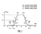
- FIG. 1shows an ideal IF total transmission curve of a television set
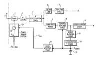
- FIG. 2shows the signal path between antenna input and signal output of the IF demodulator of a television set.
- FIG. 1shows in a diagram using the amplitude profile of a normalized gain u/u max by way of example that region of the IF total transmission curve which is essential for a video signal, on a linear scale with the respective position of vision carrier BT and colour subcarrier FT at e.g. 38.9 MHz and 34.47 MHz, respectively, in accordance with the European television standard B according to the CCIR Standard (solid line).
- the vision carrier BT and the colour subcarrier FThave standard-conforming frequency spacings from the corresponding carrier frequencies of the television channels of the same standard.
- BT′ and FT′designate the respective vision carrier and colour subcarrier on account of detuning—according to the invention—of a tuner 2 illustrated in FIG. 2 .
- detuningis intended to effect shifting (broken line) of the vision carrier BT relative to the total transmission curve: as is illustrated by the lowering of the vision carrier level and the associated raising of the colour subcarrier level, in this case low frequency components of the video signal are lowered, while the high frequency components—which effect greater detail resolution—of the video signal are raised in a defined manner (or lowered in the case of detuning according to the invention in a different direction).
- FIG. 2shows the signal receiving region of a television set in a greatly simplifying manner using a block diagram with an illustration of the tuner 2 connected to a receiving antenna 1 , of an IF stage 3 and of an IF demodulation stage 4 , the IF stage 3 comprising amplifier and selection means with a surface acoustic wave filter that is customary in today's television sets.
- a CVBS signal obtained by the IF demodulation stage 4is fed to signal paths known per se for the processing of luminance and chrominance signals: a delay line 5 and downstream amplifier stages 6 form the luminance signal path in this case, and a bandpass filter 7 is provided for separating the chrominance signal or the carried chrominance signal from the CVBS signal.
- the control amplifier stage 8is part of a control circuit of which, with a burst blanking stage 10 , a control voltage generator stage 11 and a control voltage (U control ) carrying capacitor 12 , further parts which are essential for the colour contrast control are illustrated.
- the present inventionmakes use, for a first embodiment already mentioned, of the fact that—on account of the position of the colour subcarrier FT on a tilted slope of the IF transmission curve—even instances of slight detuning of the tuner 2 would cause visible colour contrast changes if these were not corrected by the automatic colour contrast control.
- the colour contrastis kept constant by this colour contrast control in order that the colours always—i.e. irrespective of the respective amplitude of the colour burst—have their correct colour saturation.
- the control voltage U controlcan also be used as a measure of detuning of the tuner 2 and thus, at the same time, also as a measure of the video frequency response.
- control voltage U controlis fed to a level adapting stage 13 in order to obtain from the control voltage U control a correction voltage U corr. , which is used as a correction value for the video frequency response and is fed to a tuner tuning system 21 —e.g. of the type of the digital tuning system TUA 6010XS (TV Mixer-Oscillator-PLL) from Siemens, which system can be controlled via an I 2 C bus—in order to obtain the video frequency response sought together with a channel tuning voltage U tun. generated for the corresponding television channel in the tuner tuning system 21 .
- a tuner tuning system 21e.g. of the type of the digital tuning system TUA 6010XS (TV Mixer-Oscillator-PLL) from Siemens, which system can be controlled via an I 2 C bus—in order to obtain the video frequency response sought together with a channel tuning voltage U tun. generated for the corresponding television channel in the tuner tuning system 21 .
- the feeding of the correction voltage U corr. together with the tuning voltage U tun.can be effected e.g. in a simple manner by means of an addition circuit 22 .
- the level adapting stage 13is preferably designed as an electronically adjustable voltage divider which is programmable e.g. via control, data and address lines, designed as an I 2 C bus, for corresponding settings and channel assignments of the correction voltage U corr. .
- the tuning system 21essentially contains a frequency synthesis generator according to the PLL (Phase-Locked Loop) principle with a PLL circuit for generating the desired channel frequencies with a divider, control, data and address lines designed as an I 2 C bus for the organization sequence during the transmitter search with storage of channel- and programme-location-related data, and electrically programmable and addressable tuning memories for the assignment of tuning information and programme location numbers.
- PLLPhase-Locked Loop
- the correction voltage U corr. used as the correction value in the relevant channelis obtained by continuously comparing the measurement signal with a reference value U ref. .
- a reference value U ref.With reception of the measurement signal on an arbitrary channel, such a reference value U ref. can be defined as early as in the set development phase by means of a corresponding channel fine detuning.
- the channel fine detuningis preferably effected not in the customary manner known per se (i.e. by means of the tuner) but by adjustment or setting of the reference value U ref. .
- an electronically adjustable voltage dividerwhich is programmable e.g. via control, data and address lines, designed as an I 2 C bus, for corresponding settings and channel assignments of the reference value U ref. .
- the correction valueis determined from the measurement of the measurement signal with corresponding shifting of the vision carrier relative to the IF total transmission curve by means of the channel fine tuning of the tuner and is subsequently stored.
- the tuning system 21 described hereinbeforeis augmented according to the invention by second electronically programmable and addressable tuning memories.
- the inventionhas been described using a tuner with a digital tuning system. However, it shall be pointed out that the invention can also be applied in the same way to tuners with a different tuning system, such as e.g. according to the voltage synthesizer principle.
Landscapes
- Engineering & Computer Science (AREA)
- Multimedia (AREA)
- Signal Processing (AREA)
- Television Receiver Circuits (AREA)
- Circuits Of Receivers In General (AREA)
- Testing, Inspecting, Measuring Of Stereoscopic Televisions And Televisions (AREA)
Abstract
Description
Claims (10)
Applications Claiming Priority (2)
| Application Number | Priority Date | Filing Date | Title |
|---|---|---|---|
| DE19957365 | 1999-11-29 | ||
| DE19957365ADE19957365A1 (en) | 1999-11-29 | 1999-11-29 | Video frequency response improvement |
Publications (1)
| Publication Number | Publication Date |
|---|---|
| US6697128B1true US6697128B1 (en) | 2004-02-24 |
Family
ID=7930697
Family Applications (1)
| Application Number | Title | Priority Date | Filing Date |
|---|---|---|---|
| US09/722,764Expired - LifetimeUS6697128B1 (en) | 1999-11-29 | 2000-11-27 | Video frequency response |
Country Status (5)
| Country | Link |
|---|---|
| US (1) | US6697128B1 (en) |
| EP (1) | EP1104184A3 (en) |
| JP (1) | JP2001189899A (en) |
| CN (1) | CN100353754C (en) |
| DE (1) | DE19957365A1 (en) |
Cited By (2)
| Publication number | Priority date | Publication date | Assignee | Title |
|---|---|---|---|---|
| US20040042653A1 (en)* | 2002-08-28 | 2004-03-04 | Hu Shane Ching-Feng | Automatic color constancy for image sensors |
| US20090290066A1 (en)* | 2008-05-26 | 2009-11-26 | Novatek Microelectronics Corp. | Signal adjusting circuit and video apparatus thereof |
Citations (21)
| Publication number | Priority date | Publication date | Assignee | Title |
|---|---|---|---|---|
| GB1482241A (en) | 1974-05-08 | 1977-08-10 | Indesit | Circuit for the automatic tuning of a receiver |
| US4093960A (en) | 1974-11-14 | 1978-06-06 | American Technology Corporation | Test signal generating system and method |
| US4402089A (en)* | 1981-09-16 | 1983-08-30 | Rca Corporation | Television tuning system with electronic frequency adjustment apparatus |
| DE3134727C2 (en) | 1980-09-05 | 1984-05-10 | Tokyo Shibaura Denki K.K., Kawasaki, Kanagawa | Circuit arrangement for determining the operating status and for the tuning display of a television set |
| US4485404A (en)* | 1982-09-01 | 1984-11-27 | Rca Corporation | Digital aft system which is activated during vertical retrace intervals |
| US4581643A (en) | 1983-07-25 | 1986-04-08 | Rca Corporation | Double conversion television tuner with frequency response control provisions |
| GB2173365A (en) | 1985-03-23 | 1986-10-08 | I G G Electronics Limited | Tuning system for a receiver |
| US4748684A (en)* | 1986-06-03 | 1988-05-31 | Information Resources, Inc. | Fast tuning control for a television system |
| EP0314873A1 (en) | 1987-11-05 | 1989-05-10 | GRUNDIG E.M.V. Elektro-Mechanische Versuchsanstalt Max Grundig holländ. Stiftung & Co. KG. | Device for automatic application of tuning voltage to tunable components of the intermediate frequency amplifier for television receivers |
| US5179726A (en)* | 1989-11-29 | 1993-01-12 | Samsung Electro-Mechanics Co., Ltd. | Automatic tuning method and apparatus of double conversion tuner |
| DE4220760A1 (en) | 1991-07-15 | 1993-01-21 | Samsung Electronics Co Ltd | AUTOMATIC FREQUENCY ADJUSTMENT METHOD AND DEVICE THEREFOR |
| EP0567343A2 (en) | 1992-04-24 | 1993-10-27 | ORION ELECTRIC CO., Ltd. | Automatic adjustment circuit for analog control unit |
| US5353117A (en) | 1992-10-30 | 1994-10-04 | Lucasarts Entertainment Company | Vertical interval test signal for detecting video system low-level luminance linearity and differential gain and phase errors |
| US5428405A (en) | 1993-03-13 | 1995-06-27 | Goldstar Co., Ltd. | Apparatus for finely adjusting tuning data for a television receiver and the method thereof |
| DE29516956U1 (en) | 1995-05-22 | 1995-12-21 | Mb Video Gmbh, 31228 Peine | Device for evaluating the signal strength of a television signal received with a tuner |
| DE19650313A1 (en) | 1995-12-05 | 1997-06-12 | Lg Electronics Inc | Self-diagnostic system with key matrix for television receiver |
| DE19602573A1 (en) | 1996-01-25 | 1997-08-07 | Grundig Ag | Tuner for receiving digital signals |
| US5877822A (en) | 1995-06-12 | 1999-03-02 | Thomson Multimedia S.A. | Method for storing digital channel tuning data, and circuit, television receiver and video cassette recorder implementing the method |
| US5959700A (en) | 1995-01-25 | 1999-09-28 | Mitsubishi Denki Kabushiki Kaisha | Automatic tuning apparatus for a video tape signal |
| US6188970B1 (en)* | 1997-09-19 | 2001-02-13 | Temic Semiconductor Gmbh | Method of calibrating a multistage selective amplifier |
| US6369857B1 (en)* | 1999-05-13 | 2002-04-09 | Sarnoff Corporation | Receiver for analog and digital television signals |
- 1999
- 1999-11-29DEDE19957365Apatent/DE19957365A1/ennot_activeWithdrawn
- 2000
- 2000-11-17EPEP00125061Apatent/EP1104184A3/ennot_activeWithdrawn
- 2000-11-27USUS09/722,764patent/US6697128B1/ennot_activeExpired - Lifetime
- 2000-11-28CNCNB001283936Apatent/CN100353754C/ennot_activeExpired - Fee Related
- 2000-11-29JPJP2000363141Apatent/JP2001189899A/enactivePending
Patent Citations (21)
| Publication number | Priority date | Publication date | Assignee | Title |
|---|---|---|---|---|
| GB1482241A (en) | 1974-05-08 | 1977-08-10 | Indesit | Circuit for the automatic tuning of a receiver |
| US4093960A (en) | 1974-11-14 | 1978-06-06 | American Technology Corporation | Test signal generating system and method |
| DE3134727C2 (en) | 1980-09-05 | 1984-05-10 | Tokyo Shibaura Denki K.K., Kawasaki, Kanagawa | Circuit arrangement for determining the operating status and for the tuning display of a television set |
| US4402089A (en)* | 1981-09-16 | 1983-08-30 | Rca Corporation | Television tuning system with electronic frequency adjustment apparatus |
| US4485404A (en)* | 1982-09-01 | 1984-11-27 | Rca Corporation | Digital aft system which is activated during vertical retrace intervals |
| US4581643A (en) | 1983-07-25 | 1986-04-08 | Rca Corporation | Double conversion television tuner with frequency response control provisions |
| GB2173365A (en) | 1985-03-23 | 1986-10-08 | I G G Electronics Limited | Tuning system for a receiver |
| US4748684A (en)* | 1986-06-03 | 1988-05-31 | Information Resources, Inc. | Fast tuning control for a television system |
| EP0314873A1 (en) | 1987-11-05 | 1989-05-10 | GRUNDIG E.M.V. Elektro-Mechanische Versuchsanstalt Max Grundig holländ. Stiftung & Co. KG. | Device for automatic application of tuning voltage to tunable components of the intermediate frequency amplifier for television receivers |
| US5179726A (en)* | 1989-11-29 | 1993-01-12 | Samsung Electro-Mechanics Co., Ltd. | Automatic tuning method and apparatus of double conversion tuner |
| DE4220760A1 (en) | 1991-07-15 | 1993-01-21 | Samsung Electronics Co Ltd | AUTOMATIC FREQUENCY ADJUSTMENT METHOD AND DEVICE THEREFOR |
| EP0567343A2 (en) | 1992-04-24 | 1993-10-27 | ORION ELECTRIC CO., Ltd. | Automatic adjustment circuit for analog control unit |
| US5353117A (en) | 1992-10-30 | 1994-10-04 | Lucasarts Entertainment Company | Vertical interval test signal for detecting video system low-level luminance linearity and differential gain and phase errors |
| US5428405A (en) | 1993-03-13 | 1995-06-27 | Goldstar Co., Ltd. | Apparatus for finely adjusting tuning data for a television receiver and the method thereof |
| US5959700A (en) | 1995-01-25 | 1999-09-28 | Mitsubishi Denki Kabushiki Kaisha | Automatic tuning apparatus for a video tape signal |
| DE29516956U1 (en) | 1995-05-22 | 1995-12-21 | Mb Video Gmbh, 31228 Peine | Device for evaluating the signal strength of a television signal received with a tuner |
| US5877822A (en) | 1995-06-12 | 1999-03-02 | Thomson Multimedia S.A. | Method for storing digital channel tuning data, and circuit, television receiver and video cassette recorder implementing the method |
| DE19650313A1 (en) | 1995-12-05 | 1997-06-12 | Lg Electronics Inc | Self-diagnostic system with key matrix for television receiver |
| DE19602573A1 (en) | 1996-01-25 | 1997-08-07 | Grundig Ag | Tuner for receiving digital signals |
| US6188970B1 (en)* | 1997-09-19 | 2001-02-13 | Temic Semiconductor Gmbh | Method of calibrating a multistage selective amplifier |
| US6369857B1 (en)* | 1999-05-13 | 2002-04-09 | Sarnoff Corporation | Receiver for analog and digital television signals |
Non-Patent Citations (1)
| Title |
|---|
| German Search Report (with translation) citing the above-listed references: AM, AN, AO, AP, AQ, and AR. |
Cited By (5)
| Publication number | Priority date | Publication date | Assignee | Title |
|---|---|---|---|---|
| US20040042653A1 (en)* | 2002-08-28 | 2004-03-04 | Hu Shane Ching-Feng | Automatic color constancy for image sensors |
| US7110598B2 (en)* | 2002-08-28 | 2006-09-19 | Micron Technology, Inc. | Automatic color constancy for image sensors |
| US20090290066A1 (en)* | 2008-05-26 | 2009-11-26 | Novatek Microelectronics Corp. | Signal adjusting circuit and video apparatus thereof |
| TWI387335B (en)* | 2008-05-26 | 2013-02-21 | Novatek Microelectronics Corp | Signal adjusting circuit and video apparatus thereof |
| US8842221B2 (en)* | 2008-05-26 | 2014-09-23 | Novatek Microelectronics Corp. | Signal adjusting circuit and video apparatus thereof |
Also Published As
| Publication number | Publication date |
|---|---|
| EP1104184A3 (en) | 2001-12-19 |
| CN1298257A (en) | 2001-06-06 |
| EP1104184A2 (en) | 2001-05-30 |
| DE19957365A1 (en) | 2001-05-31 |
| CN100353754C (en) | 2007-12-05 |
| JP2001189899A (en) | 2001-07-10 |
Similar Documents
| Publication | Publication Date | Title |
|---|---|---|
| US6204884B1 (en) | Multisystem television which is usable as a monitor of a personal computer and a method thereof | |
| CA1239215A (en) | Television receiver having character generator with burst locked pixel clock and correction for non- standard video signals | |
| US4855812A (en) | Picture synthesizing apparatus with gain control system | |
| KR100270777B1 (en) | Apparatus for positioning a timing signal relative to a synchronization signal derived in the deflection section of a television system | |
| US7564503B2 (en) | Television tuner for controlling directivity of an antenna | |
| US7443455B2 (en) | Automatic gain control based on multiple input references in a video decoder | |
| US4774580A (en) | Video signal control apparatus | |
| US6697128B1 (en) | Video frequency response | |
| US7123310B2 (en) | Digital/analog television signal receiver using analog signal channel fine-tuning data for setting digital signal channels | |
| US4059838A (en) | Chroma-preference control for VIR automatic operation | |
| US3740459A (en) | Automatic tint control circuit | |
| CA1214863A (en) | On-screen display | |
| US2550960A (en) | Television receiver contrast and brightness control | |
| US4410913A (en) | Tuning display for a television receiver | |
| EP1104203A2 (en) | Video frequency response adaptation | |
| US5396296A (en) | Video feedback matching circuit and method therefor | |
| US4183048A (en) | VIR-controlled hue correction circuit | |
| US7525603B2 (en) | Television tuner for controlling directivity of an antenna | |
| KR19980052942A (en) | Television receiver with automatic adjustment of volume level fluctuations per channel | |
| KR100754331B1 (en) | TV automatic gain control method | |
| US4156251A (en) | Color television receiving apparatus | |
| KR0141220B1 (en) | TV signal receiving circuit of video tape recorder | |
| JPH09121365A (en) | Multi color signal processing circuit | |
| KR100211462B1 (en) | The white balance correcting apparatus of tv receiver | |
| KR100716864B1 (en) | In-vehicle television auto-tuning device and method |
Legal Events
| Date | Code | Title | Description |
|---|---|---|---|
| AS | Assignment | Owner name:DEUTSCHE THOMSON-BRANDT GMBH, GERMANY Free format text:ASSIGNMENT OF ASSIGNORS INTEREST;ASSIGNORS:SOWIG, HELMUT;SAUTER, REINHARD;REEL/FRAME:011343/0155 Effective date:20001106 | |
| AS | Assignment | Owner name:THOMSON LICENSING S.A., FRANCE Free format text:ASSIGNMENT OF ASSIGNORS INTEREST;ASSIGNOR:DEUTSCHE THOMSON-BRANDT GMBH;REEL/FRAME:014230/0364 Effective date:20040105 | |
| STCF | Information on status: patent grant | Free format text:PATENTED CASE | |
| CC | Certificate of correction | ||
| FPAY | Fee payment | Year of fee payment:4 | |
| FPAY | Fee payment | Year of fee payment:8 | |
| AS | Assignment | Owner name:THOMSON LICENSING S.A., FRANCE Free format text:CORRECTIVE ASSIGNMENT TO CORRECT THE INCORRECT APPL. NO. 09/772,764 PREVIOUSLY RECORDED AT REEL: 014230 FRAME: 0364. ASSIGNOR(S) HEREBY CONFIRMS THE ASSIGNMENT;ASSIGNOR:DEUTSCHE THOMSON-BRANDT GMBH;REEL/FRAME:033838/0062 Effective date:20040105 | |
| FPAY | Fee payment | Year of fee payment:12 |