US6697091B1 - Systems, methods and graphical user interfaces for indicating a desired original document orientation for image capture devices - Google Patents
Systems, methods and graphical user interfaces for indicating a desired original document orientation for image capture devicesDownload PDFInfo
- Publication number
- US6697091B1 US6697091B1US09/487,272US48727200AUS6697091B1US 6697091 B1US6697091 B1US 6697091B1US 48727200 AUS48727200 AUS 48727200AUS 6697091 B1US6697091 B1US 6697091B1
- Authority
- US
- United States
- Prior art keywords
- orientation
- image
- document
- image capture
- original document
- Prior art date
- Legal status (The legal status is an assumption and is not a legal conclusion. Google has not performed a legal analysis and makes no representation as to the accuracy of the status listed.)
- Expired - Fee Related
Links
- 238000000034methodMethods0.000titleclaimsabstractdescription51
- 230000000007visual effectEffects0.000claimsabstractdescription15
- 230000003278mimic effectEffects0.000claimsdescription54
- 230000008859changeEffects0.000claimsdescription13
- 230000004044responseEffects0.000claimsdescription6
- 238000013481data captureMethods0.000description9
- 238000004891communicationMethods0.000description4
- 238000010586diagramMethods0.000description4
- 230000003287optical effectEffects0.000description3
- 230000001629suppressionEffects0.000description3
- 230000006870functionEffects0.000description2
- 238000005457optimizationMethods0.000description2
- 230000008520organizationEffects0.000description2
- 230000002093peripheral effectEffects0.000description2
- 238000003825pressingMethods0.000description2
- 238000012545processingMethods0.000description2
- 230000003213activating effectEffects0.000description1
- 230000006399behaviorEffects0.000description1
- 230000010267cellular communicationEffects0.000description1
- 230000001413cellular effectEffects0.000description1
- 238000013461designMethods0.000description1
- 238000003384imaging methodMethods0.000description1
- 230000003993interactionEffects0.000description1
- 238000004519manufacturing processMethods0.000description1
- 238000012986modificationMethods0.000description1
- 230000004048modificationEffects0.000description1
- 238000011022operating instructionMethods0.000description1
- 230000003134recirculating effectEffects0.000description1
- 230000003068static effectEffects0.000description1
- 238000003860storageMethods0.000description1
- 238000012546transferMethods0.000description1
Images


Classifications
- H—ELECTRICITY
- H04—ELECTRIC COMMUNICATION TECHNIQUE
- H04N—PICTORIAL COMMUNICATION, e.g. TELEVISION
- H04N1/00—Scanning, transmission or reproduction of documents or the like, e.g. facsimile transmission; Details thereof
- H04N1/387—Composing, repositioning or otherwise geometrically modifying originals
- H04N1/3877—Image rotation
Definitions
- This inventionis directed to a graphical user interface for an image capture device, such as a scanner.
- Scanners and other types of image capture deviceshave become ubiquitous office productivity tools for generating electronic images of physical original documents. Once an electronic image of a physical original document has been generated, the electronic image data can be used in an infinite variety of ways to increase the productivity and the product quality of an office.
- image capture devicesinclude desktop scanners, other stand-alone scanners, digital still cameras, digital video cameras, the scanning input portions of digital copiers, facsimile machines and other multi-function devices that are capable of generating electronic image data from an original document, and the like.
- These image capture devicescan also include image databases that store previously captured electronic image data.
- TWAINTM interfaceallows any TWAINTM-compliant application program to input and use electronic image data using any TWAINTM-compliant image capture device.
- the TWAINTM-compliant component protocolfacilitates communication between application programs and image capture devices, such as those indicated above.
- One such TWAINTM image capture deviceis the XEROX® DigiPathTM scanner.
- image capturing devicessuch as the Xerox® DigiPathTM scanner cause users of these image capturing devices to find it increasingly difficult to obtain the desired scanning results.
- original documentsare often provided to an image capture device in such a way that the resulting captured images, when provided to an imaging application, are upside down, rotated 90°, or cut off. These incorrect orientations occur because the original documents were incorrectly loaded into the image capture device.
- image capture devicessuch as the exemplary production scanner 100 shown in FIG. 1, have markings on the document handler 130 that indicate how the original documents are to be put into the scanner.
- This inventionthus provides systems, methods and graphical user interfaces that allow the user to select the orientation of an image capture operation of an original document.
- This inventionseparately provides systems, methods and graphical user interfaces that indicate to an operator the orientation an original document should have when fed into the image capture device to obtain a captured image having the desired orientation
- a document orientation portion, or input document mimic, of the graphical user interfacesprovides a visual indication to the user of the orientation of the original documents to be captured that will result in the desired orientation of the captured image being obtained.
- the systems, methods and graphical user interfaces of this inventiondetermine and display one or more visual cues to the user that indicate the orientation of the original document that will allow the image capture device to capture an image of the original document that corresponds to the image capture parameters selected by the user.
- an image orientation portion of the graphical user interfacesallows the user to specify the orientation of the original document to be used when capturing an image of the original documents.
- the systems, methods and graphical user interfaces of this inventionaid the user in selecting the proper other image capture parameters that should be used with the selected orientation of the original document.
- FIG. 1is a perspective drawing of an exemplary electronic image generating device
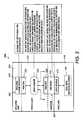
- FIG. 2is a block diagram illustrating a first exemplary embodiment of the structure of an image capture device control system that incorporates the various exemplary embodiments of the image previewing systems, methods and graphical user interfaces of this invention
- FIG. 3is a second exemplary embodiment of an image capture and usage system that incorporates the systems and methods of this invention.
- FIG. 4is an exemplary embodiment of a scan ticket illustrating various image scanning parameters according to this invention.
- FIG. 5is a block diagram of a second exemplary embodiment of the image capture control system that incorporates the image previewing systems, methods and graphical user interfaces of this invention
- FIG. 6is a graphical user interface incorporating the document orientation portion according to this invention.
- FIGS. 7-12show in greater detail various exemplary embodiments of document orientation visual cues usable with the document orientation portion of the graphical user interface shown in FIG. 6;
- FIGS. 13A and 13Bare a flowchart outlining one exemplary embodiment of a method for generating, displaying and using the document orientation portion and visual cues according to this invention.
- FIG. 1illustrates a first exemplary embodiment of an electronic image data capturing device 100 usable with the image previewing systems, methods and graphical user interfaces of this invention.
- the electronic image data capture device 100includes a control panel 110 , a document platen 120 on which an original document can be placed to generate corresponding electronic image data and a document handler 130 .
- the document handler 130includes a feed tray 131 on which the original document can be placed and a document feeder 132 which moves each document in turn from the feed tray 131 and feeds the removed document to the document platen 120 .
- Each documentis then returned to an output tray 133 after electronic image data is generated from that original document.
- the electronic image data capture devicecan also be referred to as variously, a scanner, an image capture device, an electronic image data generating device, or the like, and, regardless of the name, can be any one of a stand-alone scanner, a digital copier, a facsimile machine, a multi-function device, a digital still camera, a digital video camera, an electronic image database storing previously generated electronic image data, or any other known or later device that is capable of generating (or supplying) electronic image data from an original document.
- FIG. 2is a block diagram illustrating a first exemplary embodiment of the structural organization of an image capture device control system 200 that incorporates the image previewing systems, methods and graphical user interfaces according to this invention.
- the image capture device control system 200includes a device layer 210 , an acquisition layer 220 , a protocol layer 230 , and an application layer 240 .
- the device layer 210includes the image capture device 100 , such as a Xerox® DigiPathTM color scanner or any of the other electronic image data capture devices indicated above.
- the device layer 210also includes a device interface portion 212 of a TWAINTM driver, or TWAINTM data source, 250 .
- the TWANTM driver (or data source) 250bridges the device layer 210 , the acquisition layer 220 and the protocol layer 230 .
- the protocol layer 230includes a TWAINTM code portion 232 of the TWANTM driver (or data source) 250 , a source manager 234 and a TWAINTM code portion 236 of a TWAINTM-compliant application 260 .
- the application layer 240includes the application portion 242 of the application 260 .
- control and data signalsare provided from the electronic image data capture device 100 to the TWAINTM driver (or data source) 250 through the device interface portion 212 of the TWAINTM driver (or data source) 250 .
- control and data signalsbetween the TWAINTM driver (or data source) 250 and the source manager through the TWAINTM code portion 232 of the TWAINTM driver (or data source) 250 .
- the control and/or data signalsare also provided between the source manager 234 and the application 260 through the TWAINTM code portion 236 .
- the TWAINTM driver (or data source) 250controls the electronic image data capture device 100 .
- the TWAINTM driver or data source 250is developed by the manufacturer of the electronic image data capture device 100 .
- the source manager 234manages and facilitates the interactions between the application 260 and the TWAINTM driver or data source 250 .
- one or more of two distinct source managers 234have been implemented. Both are compiled as dynamic loading library modules.
- One exemplary dynamic load library implementation of the source manager 234is a 16-bit program developed for, for example, Microsoft® Windows® 3.1.
- the other dynamic load library implementation of the source manager 234is a 32-bit program developed for Windows® 95/98 and Windows® NT 4.0/5.0.
- these two dynamic load library modulesare provided as part of the TWAINTM developers tool kit and are shipped with each TWAINTM-compliant application and at each TWAINTM-compliant electronic image data generating device.
- FIG. 3illustrates one exemplary embodiment for accessing the systems, methods and graphical user interfaces according to this invention.
- a FILE menu 262 of a TWAINTM compliant application 260will include a plurality of menu items that provide an interface to a TWAINTM compliant electronic image data capture device 100 , such as a TWAINTM-compliant scanner.
- These menu itemsinclude various ones of at least an Acquire menu item 263 , a Select Source menu item 264 or a Scan Set-Up menu item 265 .
- selecting the Acquire menu item 263causes the application 260 to request that the electronic image data capture device 100 prepare to capture electronic image data from an original document and/or transfer capture electronic image data to the image capture device control system.
- the application 260can display its own graphical user interface.
- the TWAINTM driver (or data source) 250 for the selected electronic image data capture devicecan display one of its graphical user interfaces.
- the Scan Set up menu item 265was selected, the TWAINTM driver (or data source) 250 can display a specific Scanner Set-Up graphical user interface.
- the application 260calls the source manager 234 .
- the source manageraccesses each TWAINTM driver (or data source) 250 that is present in the image capture device control system 200 .
- the source manager 234displays, in a graphical user interface 235 , all of the different TWAINTM drivers (or data sources) 250 present on the image capture device control system 200 .
- the TWAINTM driver (or data source) 250will display a graphical user interface 400 that allows the user to select various ones of the image capture parameters and scanning control functions implemented in that TWAINTM driver (or data source) 250 .
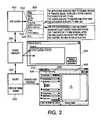
- FIG. 4illustrates one exemplary embodiment of a scan ticket 300 .
- Scan ticketscontain all of the settings in the TWAINTM graphical user interface 400 , which is discussed in greater detail below.
- the TWAINTM graphical user interface 400is displayed, only those sets of saved scan parameters, or “scan tickets” for the language the user is currently operating in are displayed.
- a set of saved scan parametersi.e., a “scan ticket”
- all the settings contained within that scan ticketare used to populate the TWAINTM graphical user interface 400 according to this invention.
- a scan ticket 300includes at least a file name portion 310 , a basic features portion 320 , an image quality portion 330 and an image size portion (not shown).
- the basic features portion 320corresponds to the basic features tab 500 of the TWAINTM graphical user interface 400 shown in FIG. 3 .
- the image quality portion 330 and the image size portioncorrespond to the image quality tab 410 and the image size tab 550 , respectively, of the graphical user interface 400 shown in FIG. 3 .
- the image quality tab 410is described in greater detail in U.S. patent application Ser. No. 09/487,271, filed Jan. 19, 2000, and incorporated herein by reference in its entirety.
- the basic features portion 320includes a scan location parameter 321 , an input original document size parameter 322 , an original image quality profile parameter 323 , a mode parameter 324 , a resolution parameter 325 , and image optimization parameter 326 .
- the image quality portion 330includes an image quality profile parameter 331 , a brightness parameter 332 , an increase/decrease parameter 333 , a special tone adjustments parameter 334 , a sharpen/soften parameter 335 , a background suppression parameter 336 and a negative image parameter 337 .
- the scan location parameter 321indicates the particular electronic image capture device that is to be used to capture electronic image data from a particular original document.
- the page size parameter portion 322indicates the size of the input document, whether the input document is single-sided or double-sided, and, if the original document is double-sided, how the two images on each side of the original document are oriented relative to each other.
- the image quality profile portion 323indicates image characteristics of and enhancements to be applied to the original document when it is made into its electronic form. Image quality profiles are described in greater detail in U.S. patent application Ser. No. 09/487,269, filed Jan. 19, 2000 and incorporated herein by reference in its entirety.
- the mode portion 324indicates the particular image capture mode to be used. For example, the image of the original document could be captured as a binary bitmap image, as shown in FIG. 4 or, as an 8-bit grayscale image, or as a color image having various color spaces and bit depths.
- the resolution portion 325indicates the resolution of the generated electronic image data.
- the image optimization portion 326indicates a particular output device, such as a particular laser printer, a particular ink jet printer, a particular digital copier, or the like, that will be used to generate hard copies of the generated electronic image data and thus for which the electronic image data should be optimized for when the electronic image data of the original document is captured.
- the image quality profile parameter 331 of the image quality portion 330is the same as the image quality profile parameter 323 .
- the lighten/darken parameter 332indicates whether the electronic image data is to be lighter or darker than the images on the original document.
- the increase/decrease contrast parameter portion 333indicates whether the contrast of the electronic image data is to be greater or less than the contrast of the images on the original document.
- the special tone adjustment parameter portion 334is used to provide finer control over the tone reproduction curve that is used to convert the continuous tone image values of the original document to the multi-bit-depth image values of the generated electronic image data. This is described in greater detail in the incorporated 271 application.
- the sharpen/soften parameter portion 335used to indicate whether the edges within the images in the original document should be sharpened or softened in the generated electronic image data.
- the background suppression parameter portion 336is used to indicate whether background suppression should be used, and if so, the color or other quality of the background of the original document that is to be suppressed.
- the negative image parameter portion 337indicates whether the generated electronic image data should be a negative image relative to the images on the original document.
- FIG. 5is a block diagram illustrating a second exemplary embodiment of the structural organization of an image captured device control system 600 that incorporates the image previewing systems methods and graphical user interfaces according to this invention.
- the image capture device control system 600includes an input/output interface 610 , a controller 620 , a memory 630 , an application layer manager 640 , a protocol layer manager 650 , and an image capture device layer manager 600 , each interconnected by a data/control bus 690 .
- the image capture device 100is connected to the input/output interface 610 using a link 102 .
- an image data sink 110can be connected to the input/output interface 610 using a link 112 .
- the links 102 and 112can each be any known or later developed device or system for connecting the image capture device 100 and the image data sink 110 , respectively, to the image capture device control 600 , including a direct cable connection, a connection over a wide area network or a local area network, a connection over an intranet, a connection over an extranet, a connection over the Internet, or a connection over any other distributed processing network or system.
- the links 102 and 112can each be any known or later developed connection system or structure usable to respectively connect the image capture device 100 and the image data sink 110 to the image capture device control system 600 . It should also be appreciated that the links 102 and 112 can be wired or wireless links that use portions of the public switch telephone network and/or portions of a cellular communication network.
- the image data sink 110can be any device that is capable of outputting or storing electronic images generated using the image capture device control system 600 using the systems, methods and graphical user interfaces according to this invention, such as a printer, a copier, any other image forming device, a facsimile device, a display device, a storage device, or the like.
- FIG. 5shows the image capture device 100 , the image capture device control system 600 and the image data sink 110 as separate devices
- the image capture device control system 600may be integrated with either or both of the image capture device 100 and/or the image data sink 110 , such as, for example, in a digital copier.
- the image capture device 100 , the image data sink 110 and the image capture device control system 600may be contained within a single device.
- the input device or devices 670can include any one or more of a mouse, a keyboard, a touch pad, a track ball, a touch screen, or the like, or any other known or later developed device that is capable of inputting data and control signals over the link 672 to the input/output interface 610 .
- the display device 680can be any known or later developed display device, including a cathode ray tube type monitor, a flat screen type monitor, an LCD monitor, or any other known or later developed device on which the graphical user interfaces according to this invention can be displayed and interacted with using one or more of the input devices 670 .
- the display device 680is provided with control and/or data signals from the input/output interface 610 over the link 682 .
- the links 672 and 682can be any known or later developed device or system for connecting the input devices 670 and the display device 680 , respectively, to the image capture device control system 600 , including a direct cable connection, a connection over a wide area network or local area network, a connection over a intranet, a connection over an extranet, a connection over the Internet, a connection over the public switched telephone network, a connection over a cellular network, or a connection over any other distributed processing or communications network or system, including both or either wired and wireless systems.
- the links 672 and 682can each be any known or later developed connection system or structure usable to connect the input devices 670 and the display device 680 , respectively, to the image capture device control system 600 .
- the memory 630includes an application portion 631 in which an application program and any application files used by that application program can be stored.
- the captured image buffer 632is used to store the captured image data input from the image capture device 110 over the signal line 102 and through the input/output interface 610 .
- the captured electronic image datawill be stored in the captured image buffer 632 under control of the controller 620 the image capture device layer manager 660 , the protocol layer manager 650 and/or the application layer manager 640 .
- the image capture profiles portion 633stores the image capture profiles, as set forth in the incorporate 269 application, as well as job tickets 300 , and the like.
- the image capture parameters portion 634stores a current set of the image capture parameters to be used by the image capture device 100 when capturing an image.
- the image capture interface portion 635stores the various graphical user interfaces shown in FIGS. 3, 4 , and 6 and as described above and in detailed below.
- the application layer manager 640manages the application layer 240 , and in particular, the application portions 242 of any executing applications 260 .
- the protocol layer manager 650manages the protocol layer 230 , including the source manager 234 .
- the protocol layer manager 650communications with the application layer manager 640 using the TWAINTM application programming interfaces 236 of the executing applications 260 .
- the image capture device layer manager 660manages each of the TWAINTM drivers (or data sources) 250 that may be implemented for different ones of the image capture devices 100 that may be accessible by the image capture device control system 600 over various ones of the links 102 .
- the image capture device layer manager 660communicates with the protocol layer manager 650 using the acquisition layer application programming interface 232 of the particular TWAINTM driver (or data source) 250 .
- the image capture device layer manager 660communications with the image capture device 100 through the input/output interface 610 and over the link 102 using the device interface portion 212 .
- the image capture device layer manager 660causes various ones of the image capture graphical user interfaces, such as the graphical user interface 400 shown in FIG. 3, to be displayed on the display device 680 .
- the usercan then change and/or input the various image capture parameters.
- the various image capture parameterscan be input through the various graphical user interfaces that the image capture device layer manager 660 displays on the display device 680 .
- the image capture device layer manager 660stores the selected image capture parameters in the image capture parameters portion 640 .
- the image capture device layer manager 660then outputs the selected image capture parameters through the input/output interface 610 and over the link 102 to the image capture device 100 .
- the image capture device 100uses the various image capture parameters received from the image capture device control system 600 when capturing electronic image data from an original document and when supplying that capture electronic image data over the link 110 to the image capture device control system 600 .
- FIG. 6shows one exemplary embodiment of the graphical user interface 400 including a document orientation portion 530 .
- the graphical user interface 400includes the image quality tab 410 and the image size tab 550 in addition to the basic features tab 500 .
- the basic features tab 500includes a scan ticket portion 510 , an original document parameters portion 520 , and an image capture parameters portion 540 .
- the basic features tab 500also includes an instance of a “How Do I” button 430 .
- the “How Do I” button 430is usable to access an operating instructions help function, which is disclosed in greater detail in the incorporated 266 application.
- the scan ticket portion 510includes a status icon 512 that indicates the saved status of the scan ticket indicated in a scan ticket selection box 514 .
- the current image capture parameters input into each of the basic features tab 500 , the image quality tab 410 and the image size tab 550can be saved to the scan ticket named in the scan ticket dialogue box 514 by selecting the save scan ticket button 516 .
- the named scan ticket displayed in the scan ticket dialogue box 514can be deleted by selecting the delete scan ticket button 517 .
- the show scan ticket button 518allows the user to quickly view all of the currently loaded scan settings in a text list. This allows the user to view the information on every setting without having to navigate all of the various dialogues in the various portions of the graphical user interface 400 .
- the original document parameters portion 520 of the basic features tab 500includes a scan location list box 522 , a page size list box 524 , a double-sided check box 526 , and an image quality profile list box 528 .
- the original document portion 520also includes a document orientation portion 530 , described in greater detail below, that allows the user to specify how the document will be oriented on the platen 120 of the image capture device 100 .
- the image quality profile list box 528allows the user to select an image quality profile.
- each image quality profileis a collection of all the settings on the image quality tab and the various dialogue boxes and other graphical user interface widgets that are accessed through the image quality tab.
- the image quality profile list box 528will include the same image quality profiles as will be provided on the image quality tab.
- the image quality profile parameters displayed in the various portions of the image quality tabwill be change accordingly.
- the image capture parameters portion 540 of the basic feature tab 500includes a mode list box 542 , a resolution list box 544 , and an optimize image list box 546 .
- the mode list box 542allows the user to select the output mode of the image capture device 100 . It should be appreciated that the particular modes displayed when the mode list box 542 is selected will depend on the particular image capture device identified in the scan location list box 522 and the particular modes available with that particular image capture device.
- the possible modesinclude, but are not limited to, 1-bit or black/white captured images, 8-bit or grayscale captured images, or various types of 24-bit captured images, including red/green/blue (RGB) color, standard red/green/blue (sRGB) color and Luminance/Blue Chromaticity/Red Chromaticity (YCbCr) color.
- RGBred/green/blue
- sRGBstandard red/green/blue
- YCbCrLuminance/Blue Chromaticity/Red Chromaticity
- the resolution list box 544allows the user to select the output resolution of the captured image, in dots per inch (dpi).
- the optimize image list box 546allows the user to select the output device for which the various captured image quality parameters on the image quality tab 410 should be set to so that the captured image, when printed on the selected output device, will provide the highest quality output image.
- the tone reproduction curve (TRC) for the 1-bit (black/white) modeis selected as the tone reproduction curve for the indicated printer.
- the document orientation portion 530includes a short edge first/long edge first (SEF/LEF) toggle button 532 , a rotate button 534 and an input document mimic portion 550 .
- the SEF/LEF toggle button 532allows the user to indicate whether the first edge of the original document to be introduced into the document handler 130 of the image capture device 100 is the long edge, such as the 11 inch edge of standard 81 ⁇ 2 ⁇ 11 inch paper, or the short edge, i.e., 81 ⁇ 2 edge of standard 81 ⁇ 2 ⁇ 11 inch paper.
- the userwill be expected to feed the original document into the document handler 130 or place it on the platen 110 in the same orientation as specified in the graphic displayed on the SEF/LEF toggle button.
- the rotate button 534allows the user to specify the orientation of the image on the input document. That is, the user may be providing the original document to the document handler using the long edge first orientation while the image has been placed onto that original document in a landscape orientation. In this case, by activating the rotate button 534 , the rotate button 534 indicates that the input image orientation is rotated 90° clockwise. This is discussed in greater detail below.
- the input document mimic portion 550is a graphic that assists the operator in putting the document into the scanner correctly to receive the desired output. That is, the input document mimic portion 550 can be used by the user to precisely identify to the image capture device the paper size and feed direction of the original document to be scanned, as well as the image orientation, so that the captured images will be returned to the calling application in the desired orientation.
- a document orientation portion 551 and an image orientation portion 552 of the input document mimic portion 550indicate, in conjunction with the SEF/LEF toggle button 532 and the rotate button 534 , the orientation the original document needs to be placed into on the image capture device in order to obtain an “upright” oriented captured image.
- An upright oriented captured imageis an image that has the orientation of the graphic 482 shown in the preview pane portion 480 of the graphical user interface 400 shown in FIG. 6 .
- the text of the captured imageis upright if the bottom-most portions of the text characters are aligned with, and are closest to, the bottom edge 483 of the page mimic 482 of the preview pane portion 480 shown in FIG. 6 .
- the input document mimic portion 550has two modes which can be selected by the user.
- “program sides and orientation” modethe user is able to select whether to feed the original documents into the image capture device using either the short edge first (SEF) orientation or the long edge first (LEF) orientation.
- the useris also able to select the orientation of the original image on the piece of paper using the rotate button 534 .
- the userselects the long edge first or short edge first orientation using the SEF/LEF toggle button 532 .
- pressing the SEF/LEF toggle button 532first selects one of the long edge first or short edge orientations. Then, pressing the SEF/LEF button again switches to the other of the short edge first or long edge first orientations.
- FIG. 7shows the SEF/LEF toggle button 532 and the document orientation portion 551 and the image orientation portion 552 , with the current state of the SEF/LEF button 532 and the document orientation portion 551 indicating the original document should be in the long edge first orientation.
- FIG. 8shows the results of a user selecting the SEF/LEF toggle button 532 , to charge the current orientation for feeding the original document into the image capture device from the long edge first orientation to the short edge first orientation. This is shown graphically by the SEF/LEF button 534 , a document handler graphic 554 , and the document orientation portion 551 in FIG. 8 .
- the graphics displayed for the SEF/LEF button 532 and the document orientation portion 551change to provide visuals cues to the user of the currently selected orientation of the original document that will result in an upright captured image.
- FIG. 8shows the input originals with the image oriented so that the top of the image is aligned with a long edge of the original document. This is commonly referred to as the “landscape” orientation.
- the image orientation portion 552 of the input document mimic portion 550rotates 90° to indicate that the originals are being fed into the scanner with the top of the image oriented toward a short edge of the original document. This is commonly referred to as the “portrait” orientation.
- the rotate button 534can be pressed repeatedly to rotate the image orientation portion 552 in 90° increments to allow the user to feed originals whose images have their top toward either short edge, or toward either long edge, of the input image.
- the userAfter the user indicates how the original document will be fed into the document handler, either short edge first or long edge first, and indicates how the image is oriented on the original document, the user then proceeds to insert the original into the feeder as indicated and the image capture device captures an image of the original document.
- the image capture devicecaptures an image of the original document.
- the second mode for the input document mimic portionis a “program sides only mode”.
- FIG. 10illustrates one exemplary embodiment of the document orientation portion 530 ′ for the program sides only mode.
- the document orientation portion 530 ′omits the rotate button 534 that appears next to the input document mimic portion 550 of the document orientation portion 530 shown in FIGS. 7-9.
- the input document mimic portion 550 of the document orientation portion 530 ′also omits the image orientation portion 551 of the input document mimic portion 550 shown in FIGS. 7-9.
- the useronly chooses whether the original document will be fed short edge first or long edge first, using the SEF/LEF toggle button 532 .
- the image of the original documentwill be captured with no concern for the orientation of the image on the original document.
- the captured imagemay therefore appear upside down, or rotated 90° when displayed in the preview pane portion 480 . This reflects a more “copier-like” behavior, where an image put into a copier upside-down will come out upside-down.
- the input document graphicscomprising an image orientation portion 551 and a document orientation portion 552 , of the input document mimic portion 550 will be altered so that the input document graphics indicate to the user the selected orientations of both the long or short edges of the input document and the image on the original document relative to the selected long edge first or short edge first orientation of the original document.
- the input document graphicscomprising only the document orientation portion 551 of the input document mimic portion 550 , will be altered so that the input document graphics indicate to the user the selected orientation of the long and short edges of the input document.
- the input document mimic portion 550indicates that the user has selected to use an automatic document handler of the image capture device, such as the document feeder 130 of the scanner 100 shown in FIG. 1 .
- the usermay not wish to use the automatic document handler, but rather may wish to place the original document by hand onto the platen of the image capture device, such as the platen 120 of the image capture device 100 shown in FIG. 1 .
- selecting the input document mimic portion 550changes the displayed input document graphics from those for the document handler graphic 554 shown in FIGS. 7-9 to those for the hand placement graphic 556 shown in FIG. 11 .
- the displayed input document graphics of the input document mimic portion 550indicate the correct orientation of the original document on the platen that will result in an upright captured image.
- selecting the desired mode and, depending on the selected mode, selecting the desired states for the SEF/LEF toggle button 532 and the rotate button 534will change the orientation of the original document in the hand placement graphic 556 shown in FIG. 11 .
- the usercan again select the input document mimic portion 550 to again change the displayed input document graphics from the hand placement graphic 556 shown in FIG. 11 to a bound document graphic 558 , as shown in FIG. 12 .
- the bound document graphic 558visually indicates to the user how the bound document is to be placed onto the platen of the image capture device in order to obtain an upright captured image.
- the states of the SEF/LEF toggle button 532 and the rotate button 534 , the orientation of the bound document orientation portion 551 and/or the image orientation portion 552 , in the bound document graphic 550will change so that a visual indication is provided to the user of the orientation of the bound document and the image of the bound document being captured.
- FIGS. 13A and 13Bare a flowchart outlining one exemplary embodiment of a method for selecting the image orientation parameters and for using the selected image orientation parameters to capture an image from an original document according to this invention.
- Controlbegins in step S 100 , upon displaying the graphical user interface that contains the image orientation widgets according to this invention.
- step S 110a determination is made whether the default mode has been selected. If so, control jumps directly to step S 150 . Otherwise, control continues to step S 120 .
- step S 120a determination is made whether the “program sides” mode has been selected. If not, then the “program sides and image orientation” mode has been selected, and control thus continues to step S 130 . Otherwise, control jumps directly to step S 140 .
- step S 130the rotate button is enabled.
- step S 140the SEF/LEF button is enabled.
- step S 150the automatic document feeder graphic is displayed using the current states of the SEF/LEF button and the rotate button.
- the states of the SEF/LEF and rotate buttonsare the default states for the particular image capture device that has been selected and cannot be changed.
- the actual states of the SEF/LEF button and/or the rotate buttonare used to determine visual cues in the particular document orientation portions and the image orientation portions of the automatic document handler graphic. Control then continues to step S 160 .
- step S 160a determination is made whether the user wishes to change the input document graphic of the input document mimic. If so, control continues to step S 170 . Otherwise, control jumps directly to step S 180 .
- step S 170the next input document graphic is displayed in the input document mimic portion using the current states for the SEF/LEF and rotate buttons. In particular, in the exemplary embodiments discussed above, if the current input document mimic is the document handler graphic, the next input document graphic is the hand placement graphic, then the bound document graphic and then back to the document feeder graphic.
- step S 180If the particular image capture device selected by the user has more or fewer available operational modes, such as lacking an automatic document feeder or having both a recirculating document feeder and a bypass document feeder, different series of displayed input document mimic graphics can be displayed. Similarly, different orders of the input document graphic can be used. Control then continues to step S 180 .
- step S 180a determination is made whether the user has changed the state of the SEF/LEF button. If so, control continues to step S 190 . Otherwise, control jumps directly to step S 200 .
- step S 190the currently displayed input document graphic is updated to change the graphics displayed in the document orientation portion and the image orientation portion of the input document graphic, based on the newly selected state of the SEF/LEF button. Control then continues to step S 200 .
- step S 200a determination is made whether the rotate state has changed. If so, control continues to step S 210 . Otherwise, control jumps to step S 220 .
- step S 210the currently displayed input document graphic is updated to change the graphics displayed in the document orientation and image orientation portions of the current input document graphic, based on the new rotate state. Control then continues to step S 220 .
- step S 220a determination is made whether the user has input or command to scan the next input document using the currently selected short or long edge first and rotation parameters, as indicated by input document mimic portion of the graphic user interface. If so, control continues to step S 230 , where an image is captured of the next input document based on these selected image capture parameters, among others. Control then continues to step S 240 .
- step S 240a determination is made whether the user has selected to change the currently selected document orientation mode. If so, control jumps to step S 110 . Otherwise, control jumps back to step S 160 .
- FIGS. 13A and 13Bthe method outlined in FIGS. 13A and 13B continues indefinitely so long as the graphical user interface containing the image orientation widgets discussed above is active.
- the image capture device control systems 200 and 600 shown in FIGS. 2 and 5can each be implemented on a general purpose computer. However, it should also be appreciated that the image capture device control systems 200 and 600 can also each be implemented on a special purpose computer, a programmed microprocessor or microcontroller and peripheral integrated circuit elements, an ASIC or other integrated circuit, a digital signal processor, a hardwired electronic or logic circuit such as a discreet element circuit, a programmable logic device such as a PLD, PLA, FPGA and/or PAL, or the like. In general, any device, capable of implementing a finite state machine, that is in turn capable of implementing the flowchart shown in FIGS. 13A and 13B, can be used to implement either of the image capture device control systems 200 or 600 .
- the memory 630 shown in FIG. 5can include both volatile and/or non-volatile alterable memory or non-alterable memory.
- Any alterable memorycan be implemented using any combination of static or dynamic RAM, a hard drive and a hard disk, flash memory, a floppy disk and disk drive, a writable optical disk and disk drive, or the like.
- Any non-alterable memorycan be implemented using any combination of ROM, PROM, EPROM, EEPROM, an optical CD-ROM disk, an optical ROM disk, such as a CD-ROM disk or a DVD-ROM disk and disk drives, or the like.
- each of the elements of the image capture device control systems 200 and 600 shown in FIGS. 2 and 5can be implemented as portions of a suitably programmed general purpose computer.
- each of the elements shown in FIGS. 2 or 5can be implemented as physically distinct hardware circuits within a ASIC, or using a FPGA, a PLD, a PLA, or a PAL, or using discreet logic elements or discreet circuit elements.
- the particular form each of the elements of the image capture device control systems 200 or 600 shown in FIGS. 2 and 5will take as a design choice and will be obvious and predictable to those skilled in the art.
- the image capture device control systems 200 or 600can each be implemented as software executing on a programmed general purpose computer, a special purpose computer, a microprocessor or the like.
- the image capture device control systems 200 and 600can be implemented as routines embedded in a peripheral driver, as a resource residing on a server, or the like.
- the image capture device control systems 200 and 600can each also be implemented by physically incorporating them into a software and/or hardware system, such as the hardware and software systems of a digital copier or the like.
Landscapes
- Engineering & Computer Science (AREA)
- Multimedia (AREA)
- Signal Processing (AREA)
- Facsimiles In General (AREA)
Abstract
Description
Claims (37)
Priority Applications (1)
| Application Number | Priority Date | Filing Date | Title |
|---|---|---|---|
| US09/487,272US6697091B1 (en) | 2000-01-19 | 2000-01-19 | Systems, methods and graphical user interfaces for indicating a desired original document orientation for image capture devices |
Applications Claiming Priority (1)
| Application Number | Priority Date | Filing Date | Title |
|---|---|---|---|
| US09/487,272US6697091B1 (en) | 2000-01-19 | 2000-01-19 | Systems, methods and graphical user interfaces for indicating a desired original document orientation for image capture devices |
Publications (1)
| Publication Number | Publication Date |
|---|---|
| US6697091B1true US6697091B1 (en) | 2004-02-24 |
Family
ID=31496116
Family Applications (1)
| Application Number | Title | Priority Date | Filing Date |
|---|---|---|---|
| US09/487,272Expired - Fee RelatedUS6697091B1 (en) | 2000-01-19 | 2000-01-19 | Systems, methods and graphical user interfaces for indicating a desired original document orientation for image capture devices |
Country Status (1)
| Country | Link |
|---|---|
| US (1) | US6697091B1 (en) |
Cited By (70)
| Publication number | Priority date | Publication date | Assignee | Title |
|---|---|---|---|---|
| US20030169447A1 (en)* | 2002-03-06 | 2003-09-11 | Matsushita Graphic Communication Systems, Inc. | Multifunctional printer and method for displaying image data to be transmitted |
| US20040017942A1 (en)* | 2002-07-24 | 2004-01-29 | Park David J. | System and method for performing optical character recognition on image data received from a document reading device |
| US20040131377A1 (en)* | 2002-10-28 | 2004-07-08 | Ulrich Bardolatzy | Operating unit with user accounts for an electro-photographic printing system or copying system |
| US20040174560A1 (en)* | 1999-05-24 | 2004-09-09 | Toshihiro Shima | Printer capable of network connection and method for controlling said printer |
| US20050105947A1 (en)* | 2003-11-17 | 2005-05-19 | Kim So-Hye | Method of indicating a paper insertion direction and a printer driver using the same |
| US20050270601A1 (en)* | 2004-05-24 | 2005-12-08 | Xerox Corporation | Systems, methods and graphical user interfaces for interactively previewing a scanned document |
| US20060265671A1 (en)* | 2005-05-20 | 2006-11-23 | Sharp Kabushiki Kaisha | Data processing setting apparatus, data processing setting method, data processing setting program, and computer readable recording medium recording the program |
| US20060265672A1 (en)* | 2005-05-20 | 2006-11-23 | Sharp Kabushiki Kaisha | Data processing setting apparatus, data processing setting method, data processing setting program, and computer-readable recording medium recording the program |
| US20070013972A1 (en)* | 2005-07-15 | 2007-01-18 | Avision Inc. | Continuous scanning method with a multi-page preview function |
| US20070106958A1 (en)* | 2005-11-08 | 2007-05-10 | Ricoh Company, Ltd. | Document management apparatus, document management program product, and computer-readable recording medium recorded with document management program |
| US20070139722A1 (en)* | 2005-12-21 | 2007-06-21 | Xerox Corporation | System and method for selective image acquisition |
| US20070212098A1 (en)* | 2006-03-09 | 2007-09-13 | Kabushiki Kaisha Toshiba | Image formig apparatus |
| USD559263S1 (en) | 2006-08-18 | 2008-01-08 | Microsoft Corporation | Icon for a portion of a display screen |
| USD562341S1 (en)* | 2006-05-23 | 2008-02-19 | Microsoft Corporation | User interface for a portion of a display screen |
| USD562342S1 (en)* | 2006-05-23 | 2008-02-19 | Microsoft Corporation | Transitional image for a portion of a display screen |
| USD562842S1 (en)* | 2006-05-23 | 2008-02-26 | Microsoft Corporation | Transitional image for a portion of a display screen |
| US20090008234A1 (en)* | 2007-07-03 | 2009-01-08 | William Haywood Tolbert | Input device and an electronic device comprising an input device |
| US20090257772A1 (en)* | 2006-03-09 | 2009-10-15 | Kabushiki Kaisha Toshiba | Image forming apparatus |
| US20100103481A1 (en)* | 2008-10-29 | 2010-04-29 | Atsuhisa Morimoto | Image processing apparatus, image forming apparatus, image reading apparatus, image processing method, and recording medium |
| US20100134825A1 (en)* | 2008-12-03 | 2010-06-03 | Xerox Corporation | Predictive user interface mimics for finishing |
| US20100316295A1 (en)* | 2009-06-15 | 2010-12-16 | Atsuhisa Morimoto | Image processing method, image processing apparatus, image forming apparatus, and storage medium |
| US20110091109A1 (en)* | 2003-03-28 | 2011-04-21 | Abbyy Software Ltd | Method of pre-analysis of a machine-readable form image |
| US20110188759A1 (en)* | 2003-06-26 | 2011-08-04 | Irina Filimonova | Method and System of Pre-Analysis and Automated Classification of Documents |
| US20120170073A1 (en)* | 2010-12-29 | 2012-07-05 | Robert Rumford | System for previewing and imaging documents |
| USD667432S1 (en)* | 2011-09-12 | 2012-09-18 | Microsoft Corporation | Display screen with icon |
| US20130033731A1 (en)* | 2008-06-23 | 2013-02-07 | Sharp Kabushiki Kaisha | Image processing apparatus, image forming apparatus, image processing method, and storage medium |
| USD676458S1 (en)* | 2010-06-05 | 2013-02-19 | Apple Inc. | Display screen or portion thereof with icon |
| USD681669S1 (en)* | 2012-01-06 | 2013-05-07 | Microsoft Corporation | Display screen with icon |
| USD681671S1 (en)* | 2012-01-06 | 2013-05-07 | Microsoft Corporation | Display screen with icon |
| USD701882S1 (en)* | 2012-08-03 | 2014-04-01 | Microsoft Corporation | Display screen with icon |
| USD705807S1 (en)* | 2013-09-06 | 2014-05-27 | Microsoft Corporation | Display screen with icon |
| USD721731S1 (en) | 2012-09-12 | 2015-01-27 | Apple Inc. | Display screen or portion thereof with graphical user interface |
| USD735755S1 (en)* | 2013-05-28 | 2015-08-04 | Deere & Company | Display screen or portion thereof with icon |
| USD754747S1 (en)* | 2013-09-03 | 2016-04-26 | Samsung Electronics Co., Ltd. | Display screen or portion thereof with icon |
| US20160162442A1 (en)* | 2014-12-03 | 2016-06-09 | Justin Esgar | Cloud based systems and methods for storing, organizing and managing portable digital format documents |
| USD762721S1 (en)* | 2014-09-26 | 2016-08-02 | Lexmark International, Inc. | Display screen portion with icon |
| USD762720S1 (en)* | 2014-09-26 | 2016-08-02 | Lexmark International, Inc. | Display screen portion with icon |
| USD764539S1 (en)* | 2014-09-26 | 2016-08-23 | Lexmark International, Inc. | Portion of a display screen with icon |
| US20160307067A1 (en)* | 2003-06-26 | 2016-10-20 | Abbyy Development Llc | Method and apparatus for determining a document type of a digital document |
| USD773510S1 (en) | 2015-06-05 | 2016-12-06 | Apple Inc. | Display screen or portion thereof with graphical user interface |
| USD774079S1 (en)* | 2014-09-26 | 2016-12-13 | Lexmark International, Inc. | Display screen portion with icon |
| USD785045S1 (en) | 2016-01-08 | 2017-04-25 | Apple Inc. | Display screen or portion thereof with group of icons |
| USD789419S1 (en) | 2014-09-01 | 2017-06-13 | Apple Inc. | Display screen or portion thereof with graphical user interface |
| USD797122S1 (en) | 2014-09-09 | 2017-09-12 | Apple Inc. | Display screen or portion thereof with animated graphical user interface |
| USD844637S1 (en) | 2018-01-17 | 2019-04-02 | Apple Inc. | Electronic device with animated graphical user interface |
| US10848665B1 (en) | 2009-08-28 | 2020-11-24 | United Services Automobile Association (Usaa) | Computer systems for updating a record to reflect data contained in image of document automatically captured on a user's remote mobile phone displaying an alignment guide and using a downloaded app |
| US10915879B1 (en) | 2007-10-23 | 2021-02-09 | United Services Automobile Association (Usaa) | Image processing |
| USD910708S1 (en) | 2018-05-08 | 2021-02-16 | Apple Inc. | Electronic device with graphical user interface |
| US10951780B2 (en)* | 2018-12-21 | 2021-03-16 | Ricoh Company, Ltd. | Image processing apparatus for easily setting direction of document and screen display method by image processing apparatus |
| US10956728B1 (en) | 2009-03-04 | 2021-03-23 | United Services Automobile Association (Usaa) | Systems and methods of check processing with background removal |
| USD914756S1 (en) | 2018-10-29 | 2021-03-30 | Apple Inc. | Electronic device with graphical user interface |
| US11023719B1 (en) | 2006-10-31 | 2021-06-01 | United Services Automobile Association (Usaa) | Digital camera processing system |
| US11030752B1 (en) | 2018-04-27 | 2021-06-08 | United Services Automobile Association (Usaa) | System, computing device, and method for document detection |
| US11062131B1 (en) | 2009-02-18 | 2021-07-13 | United Services Automobile Association (Usaa) | Systems and methods of check detection |
| US11068976B1 (en) | 2010-06-08 | 2021-07-20 | United Services Automobile Association (Usaa) | Financial document image capture deposit method, system, and computer-readable |
| US11138578B1 (en) | 2013-09-09 | 2021-10-05 | United Services Automobile Association (Usaa) | Systems and methods for remote deposit of currency |
| US11144753B1 (en) | 2013-10-17 | 2021-10-12 | United Services Automobile Association (Usaa) | Character count determination for a digital image |
| US11182753B1 (en) | 2006-10-31 | 2021-11-23 | United Services Automobile Association (Usaa) | Systems and methods for remote deposit of checks |
| US11200550B1 (en) | 2003-10-30 | 2021-12-14 | United Services Automobile Association (Usaa) | Wireless electronic check deposit scanning and cashing machine with web-based online account cash management computer application system |
| US11216884B1 (en) | 2008-09-08 | 2022-01-04 | United Services Automobile Association (Usaa) | Systems and methods for live video financial deposit |
| US11222315B1 (en) | 2009-08-19 | 2022-01-11 | United Services Automobile Association (Usaa) | Apparatuses, methods and systems for a publishing and subscribing platform of depositing negotiable instruments |
| US11321678B1 (en) | 2009-08-21 | 2022-05-03 | United Services Automobile Association (Usaa) | Systems and methods for processing an image of a check during mobile deposit |
| US11531973B1 (en) | 2008-02-07 | 2022-12-20 | United Services Automobile Association (Usaa) | Systems and methods for mobile deposit of negotiable instruments |
| US11544682B1 (en) | 2012-01-05 | 2023-01-03 | United Services Automobile Association (Usaa) | System and method for storefront bank deposits |
| USD995546S1 (en) | 2018-09-10 | 2023-08-15 | Apple Inc. | Electronic device with graphical user interface |
| US11900755B1 (en) | 2020-11-30 | 2024-02-13 | United Services Automobile Association (Usaa) | System, computing device, and method for document detection and deposit processing |
| USD1037299S1 (en) | 2017-09-10 | 2024-07-30 | Apple Inc. | Display screen or portion thereof with animated graphical user interface |
| US12100257B2 (en) | 2018-11-26 | 2024-09-24 | Capital One Services, Llc | Systems and methods for visual verification |
| US12211095B1 (en) | 2024-03-01 | 2025-01-28 | United Services Automobile Association (Usaa) | System and method for mobile check deposit enabling auto-capture functionality via video frame processing |
| US12293600B2 (en) | 2019-06-07 | 2025-05-06 | Capital One Services, Llc | Automatic image capture system based on a determination and verification of a physical object size in a captured image |
Citations (7)
| Publication number | Priority date | Publication date | Assignee | Title |
|---|---|---|---|---|
| US5260805A (en)* | 1991-08-22 | 1993-11-09 | Xerox Corporation | Process for identifying programming conflicts in electronic printing systems |
| US5301036A (en)* | 1992-04-06 | 1994-04-05 | Xerox Corporation | Image orientation control |
| US6252677B1 (en)* | 1998-05-07 | 2001-06-26 | Xerox Corporation | Method and apparatus for rendering object oriented image data using multiple rendering states selected based on imaging operator type |
| US6298172B1 (en)* | 1998-02-11 | 2001-10-02 | Lucent Technologies Inc. | Method for performing image-acquisition with preview of image to be transferred |
| US6332149B1 (en)* | 1995-06-07 | 2001-12-18 | R. R. Donnelley & Sons | Imposition process and apparatus for variable imaging system |
| US6373507B1 (en)* | 1998-09-14 | 2002-04-16 | Microsoft Corporation | Computer-implemented image acquistion system |
| US6466302B1 (en)* | 1999-04-26 | 2002-10-15 | Hewlett-Packard Company | Scanning system with document previewing |
- 2000
- 2000-01-19USUS09/487,272patent/US6697091B1/ennot_activeExpired - Fee Related
Patent Citations (7)
| Publication number | Priority date | Publication date | Assignee | Title |
|---|---|---|---|---|
| US5260805A (en)* | 1991-08-22 | 1993-11-09 | Xerox Corporation | Process for identifying programming conflicts in electronic printing systems |
| US5301036A (en)* | 1992-04-06 | 1994-04-05 | Xerox Corporation | Image orientation control |
| US6332149B1 (en)* | 1995-06-07 | 2001-12-18 | R. R. Donnelley & Sons | Imposition process and apparatus for variable imaging system |
| US6298172B1 (en)* | 1998-02-11 | 2001-10-02 | Lucent Technologies Inc. | Method for performing image-acquisition with preview of image to be transferred |
| US6252677B1 (en)* | 1998-05-07 | 2001-06-26 | Xerox Corporation | Method and apparatus for rendering object oriented image data using multiple rendering states selected based on imaging operator type |
| US6373507B1 (en)* | 1998-09-14 | 2002-04-16 | Microsoft Corporation | Computer-implemented image acquistion system |
| US6466302B1 (en)* | 1999-04-26 | 2002-10-15 | Hewlett-Packard Company | Scanning system with document previewing |
Non-Patent Citations (2)
| Title |
|---|
| Bill Camarda et al., "Using Microsoft Word 97", 1997, QUE Corporation, p. 98, 99, 107, 348-51.** |
| William Newman et al, "A Video-based Tool for Efficient Capture from Paper Source Documents", Jul. 1999, Xerox, vol. 2, pp. 647-653.* |
Cited By (129)
| Publication number | Priority date | Publication date | Assignee | Title |
|---|---|---|---|---|
| US20040174560A1 (en)* | 1999-05-24 | 2004-09-09 | Toshihiro Shima | Printer capable of network connection and method for controlling said printer |
| US20030169447A1 (en)* | 2002-03-06 | 2003-09-11 | Matsushita Graphic Communication Systems, Inc. | Multifunctional printer and method for displaying image data to be transmitted |
| US7139089B2 (en)* | 2002-03-06 | 2006-11-21 | Panasonic Communications Co., Ltd. | Multifunctional printer and method for displaying image data to be transmitted |
| US20040017942A1 (en)* | 2002-07-24 | 2004-01-29 | Park David J. | System and method for performing optical character recognition on image data received from a document reading device |
| US20040131377A1 (en)* | 2002-10-28 | 2004-07-08 | Ulrich Bardolatzy | Operating unit with user accounts for an electro-photographic printing system or copying system |
| US7050735B2 (en)* | 2002-10-28 | 2006-05-23 | Oce Printing Systems Gmbh | Operating unit with user accounts for an electro-photographic printing system or copying system |
| US20110091109A1 (en)* | 2003-03-28 | 2011-04-21 | Abbyy Software Ltd | Method of pre-analysis of a machine-readable form image |
| US8805093B2 (en)* | 2003-03-28 | 2014-08-12 | Abbyy Development Llc | Method of pre-analysis of a machine-readable form image |
| US9633257B2 (en) | 2003-03-28 | 2017-04-25 | Abbyy Development Llc | Method and system of pre-analysis and automated classification of documents |
| US10152648B2 (en)* | 2003-06-26 | 2018-12-11 | Abbyy Development Llc | Method and apparatus for determining a document type of a digital document |
| US20110188759A1 (en)* | 2003-06-26 | 2011-08-04 | Irina Filimonova | Method and System of Pre-Analysis and Automated Classification of Documents |
| US20160307067A1 (en)* | 2003-06-26 | 2016-10-20 | Abbyy Development Llc | Method and apparatus for determining a document type of a digital document |
| US11200550B1 (en) | 2003-10-30 | 2021-12-14 | United Services Automobile Association (Usaa) | Wireless electronic check deposit scanning and cashing machine with web-based online account cash management computer application system |
| US7248809B2 (en)* | 2003-11-17 | 2007-07-24 | Samsung Electronics Co., Ltd. | Method of indicating a paper insertion direction and a printer driver using the same |
| US20050105947A1 (en)* | 2003-11-17 | 2005-05-19 | Kim So-Hye | Method of indicating a paper insertion direction and a printer driver using the same |
| US7430059B2 (en)* | 2004-05-24 | 2008-09-30 | Xerox Corporation | Systems, methods and graphical user interfaces for interactively previewing a scanned document |
| US20050270601A1 (en)* | 2004-05-24 | 2005-12-08 | Xerox Corporation | Systems, methods and graphical user interfaces for interactively previewing a scanned document |
| US20060265672A1 (en)* | 2005-05-20 | 2006-11-23 | Sharp Kabushiki Kaisha | Data processing setting apparatus, data processing setting method, data processing setting program, and computer-readable recording medium recording the program |
| US20060265671A1 (en)* | 2005-05-20 | 2006-11-23 | Sharp Kabushiki Kaisha | Data processing setting apparatus, data processing setting method, data processing setting program, and computer readable recording medium recording the program |
| US7607108B2 (en)* | 2005-05-20 | 2009-10-20 | Sharp Kabushiki Kaisha | Data processing setting apparatus, data processing setting method, data processing setting program, and computer-readable recording medium recording the program |
| US7568170B2 (en)* | 2005-05-20 | 2009-07-28 | Sharp Kabushiki Kaisha | Data processing setting apparatus, data processing setting method, data processing setting program, and computer readable recording medium recording the program |
| US20070013972A1 (en)* | 2005-07-15 | 2007-01-18 | Avision Inc. | Continuous scanning method with a multi-page preview function |
| US20070106958A1 (en)* | 2005-11-08 | 2007-05-10 | Ricoh Company, Ltd. | Document management apparatus, document management program product, and computer-readable recording medium recorded with document management program |
| US20070139722A1 (en)* | 2005-12-21 | 2007-06-21 | Xerox Corporation | System and method for selective image acquisition |
| US7468806B2 (en) | 2005-12-21 | 2008-12-23 | Xerox Corporation | System and method for selective image acquisition |
| US20090257772A1 (en)* | 2006-03-09 | 2009-10-15 | Kabushiki Kaisha Toshiba | Image forming apparatus |
| US20100023856A1 (en)* | 2006-03-09 | 2010-01-28 | Kabushiki Kaisha Toshiba | Image Forming Apparatus |
| US7512354B2 (en)* | 2006-03-09 | 2009-03-31 | Kabushiki Kaisha Toshiba | Image forming apparatus and method of setting same |
| US20070212098A1 (en)* | 2006-03-09 | 2007-09-13 | Kabushiki Kaisha Toshiba | Image formig apparatus |
| US8050586B2 (en)* | 2006-03-09 | 2011-11-01 | Kabushiki Kaisha Toshiba | Image forming apparatus and display unit of an image forming apparatus |
| US8849144B2 (en)* | 2006-03-09 | 2014-09-30 | Kabushiki Kaisha Toshiba | Image forming apparatus and display unit of an image forming apparatus |
| USD562842S1 (en)* | 2006-05-23 | 2008-02-26 | Microsoft Corporation | Transitional image for a portion of a display screen |
| USD562342S1 (en)* | 2006-05-23 | 2008-02-19 | Microsoft Corporation | Transitional image for a portion of a display screen |
| USD562341S1 (en)* | 2006-05-23 | 2008-02-19 | Microsoft Corporation | User interface for a portion of a display screen |
| USD559263S1 (en) | 2006-08-18 | 2008-01-08 | Microsoft Corporation | Icon for a portion of a display screen |
| US11488405B1 (en) | 2006-10-31 | 2022-11-01 | United Services Automobile Association (Usaa) | Systems and methods for remote deposit of checks |
| US11182753B1 (en) | 2006-10-31 | 2021-11-23 | United Services Automobile Association (Usaa) | Systems and methods for remote deposit of checks |
| US11023719B1 (en) | 2006-10-31 | 2021-06-01 | United Services Automobile Association (Usaa) | Digital camera processing system |
| US11461743B1 (en) | 2006-10-31 | 2022-10-04 | United Services Automobile Association (Usaa) | Systems and methods for remote deposit of checks |
| US11544944B1 (en) | 2006-10-31 | 2023-01-03 | United Services Automobile Association (Usaa) | Digital camera processing system |
| US11562332B1 (en) | 2006-10-31 | 2023-01-24 | United Services Automobile Association (Usaa) | Systems and methods for remote deposit of checks |
| US11875314B1 (en) | 2006-10-31 | 2024-01-16 | United Services Automobile Association (Usaa) | Systems and methods for remote deposit of checks |
| US11625770B1 (en) | 2006-10-31 | 2023-04-11 | United Services Automobile Association (Usaa) | Digital camera processing system |
| US7829812B2 (en)* | 2007-07-03 | 2010-11-09 | Sony Ericsson Mobile Communications Ab | Input device and an electronic device comprising an input device |
| US20090008234A1 (en)* | 2007-07-03 | 2009-01-08 | William Haywood Tolbert | Input device and an electronic device comprising an input device |
| US10915879B1 (en) | 2007-10-23 | 2021-02-09 | United Services Automobile Association (Usaa) | Image processing |
| US12175439B1 (en) | 2007-10-23 | 2024-12-24 | United Services Automobile Association (Usaa) | Image processing |
| US11392912B1 (en) | 2007-10-23 | 2022-07-19 | United Services Automobile Association (Usaa) | Image processing |
| US11531973B1 (en) | 2008-02-07 | 2022-12-20 | United Services Automobile Association (Usaa) | Systems and methods for mobile deposit of negotiable instruments |
| US12229737B2 (en) | 2008-02-07 | 2025-02-18 | United Services Automobile Association (Usaa) | Systems and methods for mobile deposit of negotiable instruments |
| US8537443B2 (en)* | 2008-06-23 | 2013-09-17 | Sharp Kabushiki Kaisha | Image processing apparatus, image forming apparatus, image processing method, and storage medium |
| US20130033731A1 (en)* | 2008-06-23 | 2013-02-07 | Sharp Kabushiki Kaisha | Image processing apparatus, image forming apparatus, image processing method, and storage medium |
| US11694268B1 (en) | 2008-09-08 | 2023-07-04 | United Services Automobile Association (Usaa) | Systems and methods for live video financial deposit |
| US12067624B1 (en) | 2008-09-08 | 2024-08-20 | United Services Automobile Association (Usaa) | Systems and methods for live video financial deposit |
| US11216884B1 (en) | 2008-09-08 | 2022-01-04 | United Services Automobile Association (Usaa) | Systems and methods for live video financial deposit |
| US20100103481A1 (en)* | 2008-10-29 | 2010-04-29 | Atsuhisa Morimoto | Image processing apparatus, image forming apparatus, image reading apparatus, image processing method, and recording medium |
| US20100134825A1 (en)* | 2008-12-03 | 2010-06-03 | Xerox Corporation | Predictive user interface mimics for finishing |
| US8305593B2 (en) | 2008-12-03 | 2012-11-06 | Xerox Corporation | Predictive user interface mimics for finishing |
| US11062130B1 (en) | 2009-02-18 | 2021-07-13 | United Services Automobile Association (Usaa) | Systems and methods of check detection |
| US11062131B1 (en) | 2009-02-18 | 2021-07-13 | United Services Automobile Association (Usaa) | Systems and methods of check detection |
| US11749007B1 (en) | 2009-02-18 | 2023-09-05 | United Services Automobile Association (Usaa) | Systems and methods of check detection |
| US11721117B1 (en) | 2009-03-04 | 2023-08-08 | United Services Automobile Association (Usaa) | Systems and methods of check processing with background removal |
| US10956728B1 (en) | 2009-03-04 | 2021-03-23 | United Services Automobile Association (Usaa) | Systems and methods of check processing with background removal |
| US8532434B2 (en) | 2009-06-15 | 2013-09-10 | Sharp Kabushiki Kaisha | Image processing method and apparatus for determining orientations based on reliabilities of a plurality of portions into which image has been divided or for determining orientations of portions of image divided by user's input so as to recognize characters for each divided portion of image, image forming apparatus, and storage medium |
| US20100316295A1 (en)* | 2009-06-15 | 2010-12-16 | Atsuhisa Morimoto | Image processing method, image processing apparatus, image forming apparatus, and storage medium |
| US12211015B1 (en) | 2009-08-19 | 2025-01-28 | United Services Automobile Association (Usaa) | Apparatuses, methods and systems for a publishing and subscribing platform of depositing negotiable instruments |
| US11222315B1 (en) | 2009-08-19 | 2022-01-11 | United Services Automobile Association (Usaa) | Apparatuses, methods and systems for a publishing and subscribing platform of depositing negotiable instruments |
| US12159310B1 (en) | 2009-08-21 | 2024-12-03 | United Services Automobile Association (Usaa) | System and method for mobile check deposit enabling auto-capture functionality via video frame processing |
| US11373149B1 (en) | 2009-08-21 | 2022-06-28 | United Services Automobile Association (Usaa) | Systems and methods for monitoring and processing an image of a check during mobile deposit |
| US11373150B1 (en) | 2009-08-21 | 2022-06-28 | United Services Automobile Association (Usaa) | Systems and methods for monitoring and processing an image of a check during mobile deposit |
| US11341465B1 (en) | 2009-08-21 | 2022-05-24 | United Services Automobile Association (Usaa) | Systems and methods for image monitoring of check during mobile deposit |
| US11321679B1 (en) | 2009-08-21 | 2022-05-03 | United Services Automobile Association (Usaa) | Systems and methods for processing an image of a check during mobile deposit |
| US11321678B1 (en) | 2009-08-21 | 2022-05-03 | United Services Automobile Association (Usaa) | Systems and methods for processing an image of a check during mobile deposit |
| US10855914B1 (en) | 2009-08-28 | 2020-12-01 | United Services Automobile Association (Usaa) | Computer systems for updating a record to reflect data contained in image of document automatically captured on a user's remote mobile phone displaying an alignment guide and using a downloaded app |
| US12131300B1 (en) | 2009-08-28 | 2024-10-29 | United Services Automobile Association (Usaa) | Computer systems for updating a record to reflect data contained in image of document automatically captured on a user's remote mobile phone using a downloaded app with alignment guide |
| US10848665B1 (en) | 2009-08-28 | 2020-11-24 | United Services Automobile Association (Usaa) | Computer systems for updating a record to reflect data contained in image of document automatically captured on a user's remote mobile phone displaying an alignment guide and using a downloaded app |
| US11064111B1 (en) | 2009-08-28 | 2021-07-13 | United Services Automobile Association (Usaa) | Systems and methods for alignment of check during mobile deposit |
| USD676866S1 (en)* | 2010-06-05 | 2013-02-26 | Apple Inc. | Display screen or portion thereof with graphical user interface |
| USD676458S1 (en)* | 2010-06-05 | 2013-02-19 | Apple Inc. | Display screen or portion thereof with icon |
| US11068976B1 (en) | 2010-06-08 | 2021-07-20 | United Services Automobile Association (Usaa) | Financial document image capture deposit method, system, and computer-readable |
| US12400257B1 (en) | 2010-06-08 | 2025-08-26 | United Services Automobile Association (Usaa) | Automatic remote deposit image preparation apparatuses, methods and systems |
| US11915310B1 (en) | 2010-06-08 | 2024-02-27 | United Services Automobile Association (Usaa) | Apparatuses, methods and systems for a video remote deposit capture platform |
| US11893628B1 (en) | 2010-06-08 | 2024-02-06 | United Services Automobile Association (Usaa) | Apparatuses, methods and systems for a video remote deposit capture platform |
| US11295378B1 (en) | 2010-06-08 | 2022-04-05 | United Services Automobile Association (Usaa) | Apparatuses, methods and systems for a video remote deposit capture platform |
| US11295377B1 (en) | 2010-06-08 | 2022-04-05 | United Services Automobile Association (Usaa) | Automatic remote deposit image preparation apparatuses, methods and systems |
| US8699091B2 (en)* | 2010-12-29 | 2014-04-15 | Lexmark International, Inc. | System for previewing and imaging documents |
| US20120170073A1 (en)* | 2010-12-29 | 2012-07-05 | Robert Rumford | System for previewing and imaging documents |
| USD667432S1 (en)* | 2011-09-12 | 2012-09-18 | Microsoft Corporation | Display screen with icon |
| US11544682B1 (en) | 2012-01-05 | 2023-01-03 | United Services Automobile Association (Usaa) | System and method for storefront bank deposits |
| US11797960B1 (en) | 2012-01-05 | 2023-10-24 | United Services Automobile Association (Usaa) | System and method for storefront bank deposits |
| USD681669S1 (en)* | 2012-01-06 | 2013-05-07 | Microsoft Corporation | Display screen with icon |
| USD681671S1 (en)* | 2012-01-06 | 2013-05-07 | Microsoft Corporation | Display screen with icon |
| USD701882S1 (en)* | 2012-08-03 | 2014-04-01 | Microsoft Corporation | Display screen with icon |
| USD721731S1 (en) | 2012-09-12 | 2015-01-27 | Apple Inc. | Display screen or portion thereof with graphical user interface |
| USD735755S1 (en)* | 2013-05-28 | 2015-08-04 | Deere & Company | Display screen or portion thereof with icon |
| USD754747S1 (en)* | 2013-09-03 | 2016-04-26 | Samsung Electronics Co., Ltd. | Display screen or portion thereof with icon |
| USD705807S1 (en)* | 2013-09-06 | 2014-05-27 | Microsoft Corporation | Display screen with icon |
| US12182781B1 (en) | 2013-09-09 | 2024-12-31 | United Services Automobile Association (Usaa) | Systems and methods for remote deposit of currency |
| US11138578B1 (en) | 2013-09-09 | 2021-10-05 | United Services Automobile Association (Usaa) | Systems and methods for remote deposit of currency |
| US11144753B1 (en) | 2013-10-17 | 2021-10-12 | United Services Automobile Association (Usaa) | Character count determination for a digital image |
| US11281903B1 (en) | 2013-10-17 | 2022-03-22 | United Services Automobile Association (Usaa) | Character count determination for a digital image |
| US11694462B1 (en) | 2013-10-17 | 2023-07-04 | United Services Automobile Association (Usaa) | Character count determination for a digital image |
| USD789419S1 (en) | 2014-09-01 | 2017-06-13 | Apple Inc. | Display screen or portion thereof with graphical user interface |
| USD1042540S1 (en) | 2014-09-09 | 2024-09-17 | Apple Inc. | Display screen or portion thereof with graphical user interface |
| USD797122S1 (en) | 2014-09-09 | 2017-09-12 | Apple Inc. | Display screen or portion thereof with animated graphical user interface |
| USD762721S1 (en)* | 2014-09-26 | 2016-08-02 | Lexmark International, Inc. | Display screen portion with icon |
| USD774079S1 (en)* | 2014-09-26 | 2016-12-13 | Lexmark International, Inc. | Display screen portion with icon |
| USD762720S1 (en)* | 2014-09-26 | 2016-08-02 | Lexmark International, Inc. | Display screen portion with icon |
| USD764539S1 (en)* | 2014-09-26 | 2016-08-23 | Lexmark International, Inc. | Portion of a display screen with icon |
| US20160162442A1 (en)* | 2014-12-03 | 2016-06-09 | Justin Esgar | Cloud based systems and methods for storing, organizing and managing portable digital format documents |
| USD773510S1 (en) | 2015-06-05 | 2016-12-06 | Apple Inc. | Display screen or portion thereof with graphical user interface |
| USD819688S1 (en) | 2015-06-05 | 2018-06-05 | Apple Inc. | Display screen or portion thereof with graphical user interface |
| USD785045S1 (en) | 2016-01-08 | 2017-04-25 | Apple Inc. | Display screen or portion thereof with group of icons |
| US10706320B2 (en) | 2016-06-22 | 2020-07-07 | Abbyy Production Llc | Determining a document type of a digital document |
| USD1037299S1 (en) | 2017-09-10 | 2024-07-30 | Apple Inc. | Display screen or portion thereof with animated graphical user interface |
| USD844637S1 (en) | 2018-01-17 | 2019-04-02 | Apple Inc. | Electronic device with animated graphical user interface |
| US11676285B1 (en) | 2018-04-27 | 2023-06-13 | United Services Automobile Association (Usaa) | System, computing device, and method for document detection |
| US11030752B1 (en) | 2018-04-27 | 2021-06-08 | United Services Automobile Association (Usaa) | System, computing device, and method for document detection |
| USD938492S1 (en) | 2018-05-08 | 2021-12-14 | Apple Inc. | Electronic device with animated graphical user interface |
| USD910708S1 (en) | 2018-05-08 | 2021-02-16 | Apple Inc. | Electronic device with graphical user interface |
| USD995546S1 (en) | 2018-09-10 | 2023-08-15 | Apple Inc. | Electronic device with graphical user interface |
| USD1038994S1 (en) | 2018-10-29 | 2024-08-13 | Apple Inc. | Electronic device with animated graphical user interface |
| USD914756S1 (en) | 2018-10-29 | 2021-03-30 | Apple Inc. | Electronic device with graphical user interface |
| US12100257B2 (en) | 2018-11-26 | 2024-09-24 | Capital One Services, Llc | Systems and methods for visual verification |
| US10951780B2 (en)* | 2018-12-21 | 2021-03-16 | Ricoh Company, Ltd. | Image processing apparatus for easily setting direction of document and screen display method by image processing apparatus |
| US12293600B2 (en) | 2019-06-07 | 2025-05-06 | Capital One Services, Llc | Automatic image capture system based on a determination and verification of a physical object size in a captured image |
| US11900755B1 (en) | 2020-11-30 | 2024-02-13 | United Services Automobile Association (Usaa) | System, computing device, and method for document detection and deposit processing |
| US12260700B1 (en) | 2020-11-30 | 2025-03-25 | United Services Automobile Association (Usaa) | System, computing device, and method for document detection and deposit processing |
| US12211095B1 (en) | 2024-03-01 | 2025-01-28 | United Services Automobile Association (Usaa) | System and method for mobile check deposit enabling auto-capture functionality via video frame processing |
Similar Documents
| Publication | Publication Date | Title |
|---|---|---|
| US6697091B1 (en) | Systems, methods and graphical user interfaces for indicating a desired original document orientation for image capture devices | |
| US6850259B1 (en) | Systems and methods for providing original document orientation, tone reproduction curves and task specific user instructions based on displayed portions of a graphical user interface | |
| US7065716B1 (en) | Systems, methods and graphical user interfaces for previewing image capture device output results | |
| US6741270B1 (en) | Systems and methods scaling a captured image using predetermined scale information | |
| US6614456B1 (en) | Systems, methods and graphical user interfaces for controlling tone reproduction curves of image capture and forming devices | |
| US7430059B2 (en) | Systems, methods and graphical user interfaces for interactively previewing a scanned document | |
| EP1128659A1 (en) | Graphical user interface for previewing captured image data of double sided or bound documents | |
| US8477393B2 (en) | Image processing apparatus, computer program product, and preview image displaying method | |
| US6512530B1 (en) | Systems and methods for mimicking an image forming or capture device control panel control element | |
| US6798530B1 (en) | Systems, methods and graphical user interfaces for printing object optimized images using virtual printers | |
| US8004704B2 (en) | Scanner and control method for display of operation menu thereof | |
| US8407591B2 (en) | Image processing apparatus, computer program product, and preview image displaying method | |
| JP3929584B2 (en) | Apparatus for copying, scanning and printing images with improved user interface | |
| US8411290B2 (en) | User interface apparatus, image processing apparatus, and computer program product | |
| US8086961B2 (en) | Image processing apparatus, image forming apparatus, and computer program product | |
| US8390831B2 (en) | Image processing apparatus, method for same, image reading system, method of controlling image reading system | |
| US20120140253A1 (en) | Image forming apparatus to set optimal print options for test prints of primitive images and method thereof | |
| US20080278758A1 (en) | Image processing system, computer program product, and image processing method | |
| US20080131182A1 (en) | Print instructing apparatus, print system and computer-readable medium | |
| KR100615701B1 (en) | Image Forming System with Scanned Image Preview Function and Its Method | |
| JP6984190B2 (en) | Information processing equipment and programs | |
| US8310712B2 (en) | Image forming controlling apparatus, image forming controlling method, and image forming controlling program embodied on computer readable recording medium | |
| US20040165011A1 (en) | Systems and methods for controlling user-controlled devices using data stored on a portable storage medium | |
| US11483449B2 (en) | Computer-readable medium, information processing device, and method for rearranging image data | |
| US7663777B2 (en) | Default settings customization system |
Legal Events
| Date | Code | Title | Description |
|---|---|---|---|
| AS | Assignment | Owner name:XEROX CORPORATION, CONNECTICUT Free format text:ASSIGNMENT OF ASSIGNORS INTEREST;ASSIGNORS:RZEPKOWSKI, KRISTINN R.;RODRIGUES, RUDOLPH A.;YOUNG, DANIEL L.;REEL/FRAME:010548/0463;SIGNING DATES FROM 19991216 TO 20000110 | |
| AS | Assignment | Owner name:BANK ONE, NA, AS ADMINISTRATIVE AGENT, ILLINOIS Free format text:SECURITY AGREEMENT;ASSIGNOR:XEROX CORPORATION;REEL/FRAME:013111/0001 Effective date:20020621 Owner name:BANK ONE, NA, AS ADMINISTRATIVE AGENT,ILLINOIS Free format text:SECURITY AGREEMENT;ASSIGNOR:XEROX CORPORATION;REEL/FRAME:013111/0001 Effective date:20020621 | |
| AS | Assignment | Owner name:JPMORGAN CHASE BANK, AS COLLATERAL AGENT, TEXAS Free format text:SECURITY AGREEMENT;ASSIGNOR:XEROX CORPORATION;REEL/FRAME:015134/0476 Effective date:20030625 Owner name:JPMORGAN CHASE BANK, AS COLLATERAL AGENT,TEXAS Free format text:SECURITY AGREEMENT;ASSIGNOR:XEROX CORPORATION;REEL/FRAME:015134/0476 Effective date:20030625 | |
| FEPP | Fee payment procedure | Free format text:PAYOR NUMBER ASSIGNED (ORIGINAL EVENT CODE: ASPN); ENTITY STATUS OF PATENT OWNER: LARGE ENTITY | |
| AS | Assignment | Owner name:JPMORGAN CHASE BANK, AS COLLATERAL AGENT, TEXAS Free format text:SECURITY AGREEMENT;ASSIGNOR:XEROX CORPORATION;REEL/FRAME:015722/0119 Effective date:20030625 Owner name:JPMORGAN CHASE BANK, AS COLLATERAL AGENT,TEXAS Free format text:SECURITY AGREEMENT;ASSIGNOR:XEROX CORPORATION;REEL/FRAME:015722/0119 Effective date:20030625 | |
| FPAY | Fee payment | Year of fee payment:4 | |
| FPAY | Fee payment | Year of fee payment:8 | |
| REMI | Maintenance fee reminder mailed | ||
| LAPS | Lapse for failure to pay maintenance fees | ||
| STCH | Information on status: patent discontinuation | Free format text:PATENT EXPIRED DUE TO NONPAYMENT OF MAINTENANCE FEES UNDER 37 CFR 1.362 | |
| FP | Lapsed due to failure to pay maintenance fee | Effective date:20160224 | |
| AS | Assignment | Owner name:XEROX CORPORATION, CONNECTICUT Free format text:RELEASE BY SECURED PARTY;ASSIGNOR:JPMORGAN CHASE BANK, N.A. AS SUCCESSOR-IN-INTEREST ADMINISTRATIVE AGENT AND COLLATERAL AGENT TO BANK ONE, N.A.;REEL/FRAME:061360/0501 Effective date:20220822 | |
| AS | Assignment | Owner name:XEROX CORPORATION, CONNECTICUT Free format text:RELEASE BY SECURED PARTY;ASSIGNOR:JPMORGAN CHASE BANK, N.A. AS SUCCESSOR-IN-INTEREST ADMINISTRATIVE AGENT AND COLLATERAL AGENT TO BANK ONE, N.A.;REEL/FRAME:061388/0388 Effective date:20220822 Owner name:XEROX CORPORATION, CONNECTICUT Free format text:RELEASE BY SECURED PARTY;ASSIGNOR:JPMORGAN CHASE BANK, N.A. AS SUCCESSOR-IN-INTEREST ADMINISTRATIVE AGENT AND COLLATERAL AGENT TO JPMORGAN CHASE BANK;REEL/FRAME:066728/0193 Effective date:20220822 |